Kenwood USA 29521120 VHF-FM Low Band Hand Held Transceiver User Manual TK 190 E 00 Cover
Kenwood USA Corporation VHF-FM Low Band Hand Held Transceiver TK 190 E 00 Cover
Manual

INSTRUCTION MANUAL
© B62-1172-00 (K)
09 08 07 06 05 04 03 02 01 00
VHF FM TRANSCEIVER
KENWOOD CORPORATION
TK-190

◆
GOVERNMENT LAW PROHIBITS THE OPERATION OF
UNLICENSED RADIO TRANSMITTERS WITHIN THE
TERRITORIES UNDER GOVERNMENT CONTROL.
◆
ILLEGAL OPERATION IS PUNISHABLE BY FINE OR
IMPRISONMENT OR BOTH.
◆
REFER SERVICE TO QUALIFIED TECHNICIANS ONLY.
◆
DO NOT OPERATE YOUR TRANSCEIVER IN EXPLOSIVE
ATMOSPHERES (GASES, DUST, FUMES, ETC.).
◆
TURN OFF YOUR TRANSCEIVER WHILE TAKING ON FUEL,
OR WHILE PARKED IN GASOLINE SERVICE STATIONS.
THANK YOU
We are grateful you chose KENWOOD for your land
mobile radio applications. We believe this easy-to-use
transceiver will provide dependable communications to
keep personnel operating at peak efficiency.
KENWOOD transceivers incorporate the latest in
advanced technology. As a result, we feel strongly that
you will be pleased with the quality and features of this
product.
NOTICES TO THE USER
SAFETY: It is important that the operator is aware of
and understands hazards common to the operation of
any transceiver.

i
One or more of the following statements may be
applicable:
ATTENTION (U.S.A. Only):
The RBRC Recycle seal found on KENWOOD
nickel-cadmium (Ni-Cd) battery packs indicates
KENWOOD’s voluntary participation in an industry
program to collect and recycle Ni-Cd batteries after
their operating life has expired. The RBRC program
is an alternative to disposing Ni-Cd batteries with
your regular refuse or in municipal waste streams,
which is illegal in some areas.
For information on Ni-Cd battery recycling in your area, call (toll free)
1-800-8-BATTERY (1-800-822-8837).
KENWOOD’s involvement in this program is part of our commitment
to preserve our environment and conserve our natural resources.
FCC WARNING
This equipment generates or uses radio frequency energy. Changes
or modifications to this equipment may cause harmful interference
unless the modifications are expressly approved in the instruction
manual. The user could lose the authority to operate this equipment
if an unauthorized change or modification is made.
INFORMATION TO THE DIGITAL DEVICE USER REQUIRED BY
THE FCC
This equipment has been tested and found to comply with the limits
for a Class B digital device, pursuant to Part 15 of the FCC Rules.
These limits are designed to provide reasonable protection against
harmful interference in a residential installation.
This equipment generates, uses and can generate radio frequency
energy and, if not installed and used in accordance with the
instructions, may cause harmful interference to radio communications.
However, there is no guarantee that the interference will not occur in a
particular installation. If this equipment does cause harmful
interference to radio or television reception, which can be determined
by turning the equipment off and on, the user is encouraged to try to
correct the interference by one or more of the following measures:
•
Reorient or relocate the receiving antenna.
•
Increase the separation between the equipment and receiver.
•
Connect the equipment to an outlet on a circuit different from that
to which the receiver is connected.
•
Consult the dealer for technical assistance.

ii
CONTENTS
UNPACKING AND CHECKING EQUIPMENT ..........................1
Supplied Accessories .............................................1
PREPARATION ..........................................................2
Installing/ Removing the Optional NiCd Battery Pack ..........2
Installing the Optional Antenna..................................3
Installing the Belt Clip ............................................3
Installing the Cover over the Universal Connector ............4
Installing the Optional KMC-25 Speaker/ Microphone ..........4
GETTING ACQUAINTED ................................................5
Display ............................................................. 8
PROGRAMMABLE AUXILIARY FUNCTIONS .........................9
Function Descriptions........................................... 10
OPERATING BASICS ................................................. 14
Switching Power ON/OFF....................................... 14
Adjusting the Volume ........................................... 14
Selecting a Channel............................................. 14
Making a Call .................................................... 15
Adjusting the Squelch........................................... 15
SCANNING ............................................................ 16
Priority Scan ..................................................... 17
Revert Channel .................................................. 18
SIGNALLING .......................................................... 19
2-Tone Signalling................................................ 19
DTMF Signalling................................................. 20
Dead Beat Disable (DBD)....................................... 21
PTT ID............................................................. 21
QUIET TALK (QT) AND DIGITAL QUIET TALK (DQT) .............. 22
AUXILIARY FEATURES............................................... 23
Key Lock.......................................................... 23
Time-out Timer (TOT)........................................... 24
Busy Channel Lockout (BCL) ................................... 24
Voice Scrambler ................................................. 24
AUDIBLE USER FEEDBACK TONES ................................. 26

1
UNPACKING AND CHECKING EQUIPMENT
Note: The following unpacking instructions are for use by your
KENWOOD dealer, an authorized KENWOOD service facility, or the
factory.
Carefully unpack the transceiver. We recommend that
you identify the items listed in the following table before
discarding the packing material. If any items are
missing or have been damaged during shipment, file a
claim with the carrier immediately.
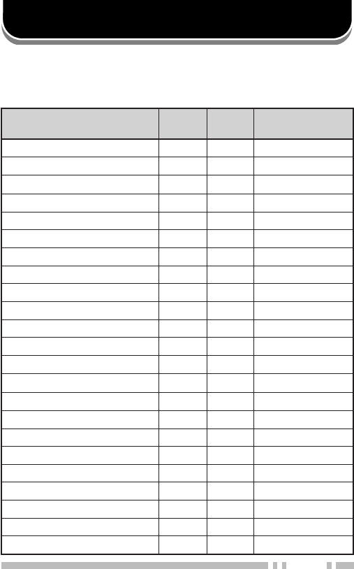
■Supplied Accessories
metI rebmuNtraP ytitnauQ
koohtleBXX-2560-92J1
lasrevinU pacrotcennoc XX-3630-90B1
laeslennahCXX-4950-30B1
reppotslennahCXX-1240-23D1
teswercSXX-4002-99N1
dracytnarraW—1
launamnoitcurtsnIXX-2711-26B1
Belt hook
Universal connector cap
Channel stopper
Channel seal Screw set
Accessory
screw
Binding
screws
2
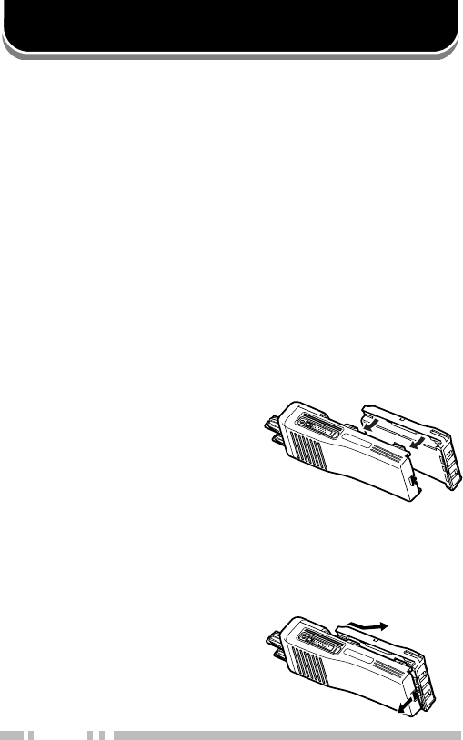
PREPARATION
1Match the four grooves of
the battery pack with the
corresponding guides on
the back of the
transceiver.
2Slide the battery pack
along the back of the
transceiver until the
release latch on the base
of the transceiver locks.
3To remove the battery
pack, pull back on the
release latch and slide
the pack away from the
transceiver.
■Installing/ Removing the Optional NiCd Battery Pack
The battery pack is not charged at the factory;
charge it before use.
CAUTION:
◆
DO NOT RECHARGE THE BATTERY PACK IF IT IS ALREADY
FULLY CHARGED. DOING SO MAY CAUSE THE LIFE OF
THE BATTERY PACK TO SHORTEN OR THE BATTERY PACK
MAY BE DAMAGED.
◆
AFTER RECHARGING THE BATTERY PACK, DISCONNECT
IT FROM THE CHARGER. IF THE CHARGER POWER IS
RESET (TURNED ON AFTER BEING TURNED OFF),
RECHARGING WILL START AGAIN AND THE BATTERY
PACK WILL BECOME OVERCHARGED.
◆
DO NOT SHORT THE BATTERY TERMINALS OR DISPOSE
OF THE BATTERY BY FIRE.
◆
NEVER ATTEMPT TO REMOVE THE CASING FROM THE
BATTERY PACK.

3
Screw the antenna into the
connector on the top of the
transceiver by holding the
antenna at its base and
turning it clockwise until
secure.
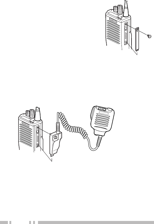
■Installing the Belt Clip
If necessary, attach the belt
clip using the two supplied
3 x 6 mm screws.
Note: If the belt clip is not installed,
its mounting location may get hot
during continuous transmission or
when left sitting in a hot
environment.
■Installing the Optional Antenna
4
If you are not using the
optional KMC-25 speaker/
microphone, install the
cover over the universal
connector using the
supplied 4 x 6 mm screw.
Note: To keep the transceiver water
resistant, you must cover the
universal connector with the cap or
the speaker/ microphone connector.
■Installing the Cover over the Universal Connector
■Installing the Optional KMC-25 Speaker/ Microphone
1Insert the guide of the speaker/ microphone
connector into the groove of the universal
connector.
2Secure the connector in place using the attached
screw.
Note: The speaker/ microphone keys can be programmed with the
programmable auxiliary functions listed on page 9.
5
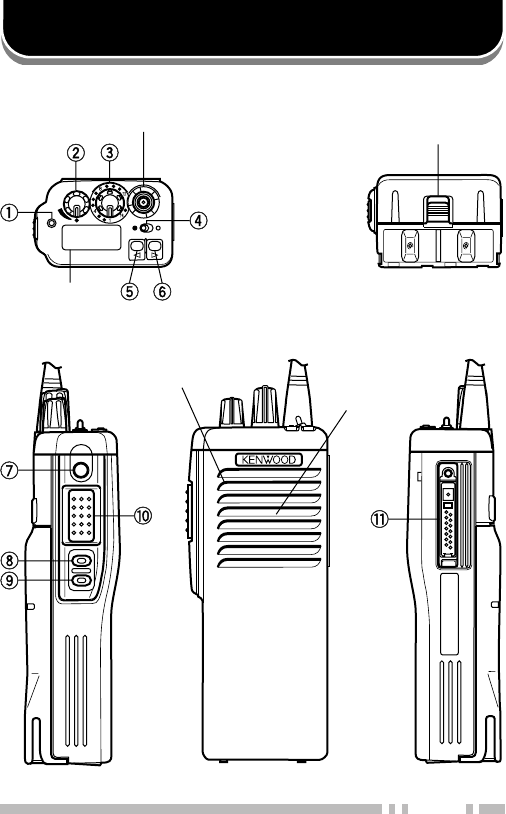
GETTING ACQUAINTED
AB
SMA male type
antenna connector Battery pack
release latch
Microphone
Speaker
Display
[Top View] [Bottom View]
[Left Side] [Front View] [Right Side]

6
qq
qq
qTX/ BUSY/ CALL/ Battery low LED
Lights red while transmitting. Lights green while
receiving. Lights orange while receiving a
2-Tone/ DTMF call. Flashes red when the battery
power is low while transmitting; replace or
recharge the battery.
Note: This LED can be disabled by your dealer.
ww
ww
wPower swit ch/ Volume control
Turn clockwise to switch the transceiver ON. Turn
counterclockwise until a click sounds, to switch
the transceiver OFF. Rotate to adjust the volume
level. Clockwise increases the volume and
counterclockwise decreases it.
Note: Your dealer can set a minimum volume level for the
Volume control.
ee
ee
eEncoder
Rotate to select a channel. Clockwise increases
the channel number and counterclockwise
decreases it.
rr
rr
rToggle switch
Switch the toggle position to the right ( O ) to
activate its programmable function {page 9} and
to the left ( ● ) to deactivate it. The default
function of this switch is “No Function”.
tt
tt
tTop 1
Press this PF (programmable function) key to
activate its programmable function {page 9}. The
default function of this key is “No Function”.
yy
yy
yTop 2
Press this PF (programmable function) key to
activate its programmable function {page 9}. The
default function of this key is “No Function”.

7
uu
uu
uOrange
Press this PF (programmable function) key to
activate its programmable function {page 9}. The
default function of this key is “No Function”.
ii
ii
iSide 1
Press this PF (programmable function) key to
activate its programmable function {page 9}. The
default function of this key is “Monitor”. Also used
as an “up” key for various functions.
oo
oo
oSide 2
Press this PF (programmable function) key to
activate its programmable function {page 9}. The
default function of this key is “Lamp”. Also used
as a “down” key for various functions.
!0!0
!0!0
!0 PTT (Push-To-Talk) switch
Press and hold this switch, then speak into the
microphone to call a station.
!1!1
!1!1
!1 Universal connector
Connect the optional KMC-25 speaker
microphone here. When the KMC-25 speaker/
microphone is not connected, cover the connector
with the supplied universal connector cover.
8
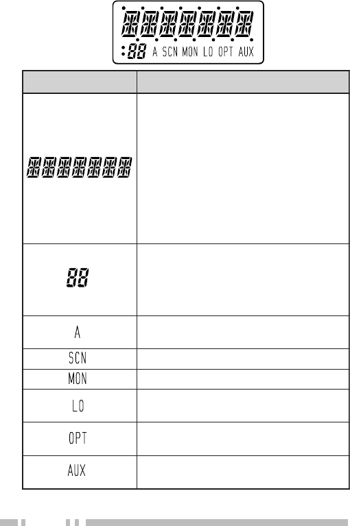
■Display
Note: You can invert the segmented displays (not the icons) if a PF
key or the toggle switch is programmed with Invert Display {page 9}.
nocI noitpircseD
lennahcgnitarepoehtsyalpsiD nehw(”GORPNU“,emanrorebmun nodemmargorpsiatadlennahcon edocTSOeht,)lennahcdetceleseht ,)edomtceleSTSOni(emanro eht,)gninnacselihw(”NACS“ ehtgnitsujdanehw(levelhcleuqs ni(edocrelbmarcseht,)hcleuqs dna,)edomtceleSedoCrelbmarcS roenoT-2agniviecernehw(”LLAC“ .)llacFMTD
lennahcgnitarepoehtsyalpsiD ruoyybdemmargorpfi(rebmun ,)dnuorAklaT(At,)ytiroirP(P,)relaed gnidneped;)lennahCemoH(CHdna .desugniebnoitcnufehtno
lennahcdetcelesehtnehwsraeppA .ecneuqesnacsehtnidedulcnisi
.gninnacselihwsraeppA
.lennahcagnirotinomelihwsraeppA
norewopwolgnisunehwsraeppA .lennahctnerruceht
elbatceleSrotarepOnehwsraeppA .delbanesienoT
lanoitpoehtnehwsraeppA .delbanesidraobrelbmarcs
9
PROGRAMMABLE AUXILIARY FUNCTIONS
The PF keys, toggle switch, and Speaker/ Microphone
keys can be programmed with the auxiliary functions
listed below:
emaNnoitcnuF elggoT hctiwS FP syeK /rekaepS syeKenohporciM
xuA
1
nwoDlennahC
emaNlennahC
pUlennahC
ddA/eteleD
llaCycnegremE
2
lennahCemoH
yalpsiDtrevnI
kcoLyeK
pmaL
rewoPwoL
rotinoM
yratnemoMrotinoM
noitcnuFoN
enoTelbatceleSrotarepO
nacS
relbmarcS
3
tfihS
noitaunettAPS
leveLhcleuqS
yratnemoMhcleuqS
FFOhcleuqS
dnuorAklaT

10
1This function can be selected only when the scrambler
board has not been installed.
2This function can be selected only when the ANI board has
been installed.
3This function can be selected only when the scrambler
board has been installed.
Note:
◆
If your dealer programs “Shift” onto a PF key or the toggle switch,
the remaining PF keys can be programmed with an additional
function. To use the additional functions, you must first press the
Shift key, then press the function key you desire. The toggle switch
and the key programmed with “Shift” cannot be programmed with an
additional function.
◆
When a function is programmed onto both a PF key and the toggle
switch, an error will occur on the PF key and it cannot be used.
■Function Descriptions
•AUX: Press to turn AUX ON. The dealer selectable
optional board will activate. Press again to turn AUX
OFF. When AUX is ON, “AUX” appears on the display.
•Channel Down: Press to decrease the channel by 1
step. Press and hold to continuously scroll through the
channels. Unprogrammed channels will be skipped.
Note: Your dealer can program the “Roll Over” (default) or
“Dead End” feature. When Roll Over is programmed, pressing
Channel Down while you are at the lowest channel will cause
the transceiver to select the highest channel, and begin the
decrease cycle again. When Dead End is programmed,
pressing Channel Down while you are at the lowest channel will
not change the channel number.
•Channel Name: Press to change the display between
the channel number and the channel name. Your
dealer can program a channel name for each channel
with up to 7 characters.

11
•Channel Up: Press to increase the channel by 1 step.
Press and hold to continuously scroll through the
channels. Unprogrammed channels will be skipped.
Note: Your dealer can program the “Roll Over” (default) or “Dead
End” feature. When Roll Over is programmed, pressing Channel
Up while you are at the highest channel will cause the
transceiver to select the lowest channel, and begin the increase
cycle again. When Dead End is programmed, pressing Channel
Up while you are at the highest channel will not change the
channel number.
•Delete/Add: Press to remove an undesired channel
from the scan sequence, or to add a desired channel to
the scan sequence. See “SCANNING” on
page 16.
•Emergency Call: Press and hold this key for the time
required (which is pre-programmed by your dealer) to
enter Emergency mode. If Emergency Channel Display
is activated by your dealer, the emergency channel
name will appear on the display and the TX LED (red)
will light.
•Home Channel: Press to change from the current
channel to your home channel. Press again to return to
the previous channel, from your home channel.
•Invert Display: Press to invert both segmented
displays (the icons do not change). This allows channel
numbers, names, and other information to be easily
read when you use the transceiver in such a way as to
have the display upside down.
•Key Lock: Press to lock most of the keys on the
transceiver. Press again to unlock the keys. See “Key
Lock” on page 23.

12
•Lamp: Press to turn the display backlight ON. The
backlight will remain ON for 5 seconds. Pressing any
key other than Lamp will reset the lamp timer, causing
it to remain ON for 5 seconds from the time you
pressed the new key. Pressing the Lamp key while the
lamp is ON will turn the lamp OFF.
•Low Power: Press to change the output power of the
current channel from high to low. Pressing this key
again will return the channel to high power. It is
recommended to use low power whenever possible (if
you are in range of the other transceiver) to conserve
your battery power. When using low power, “LO”
appears on the display.
Note: You cannot change a channel from low power to high
power if your dealer has set the channel for use with low power.
•Monitor: Press to turn the signalling squelch
{page 19} of the current channel OFF (if signalling has
been set up on the channel). Depending on the
squelch level {page 15}, you will be able to hear a
signal or background noise if there is no signal. Press
again to reactivate signalling squelch. While monitor is
active, “MON” appears on the display.
•Monitor Momentary: Press and hold to turn the
signalling squelch {page 19} of the current channel OFF
(if signalling has been set up on the channel).
Depending on the squelch level {page 15}, you will be
able to hear a signal or background noise if there is no
signal. Release to reactivate signalling squelch. While
monitor is active, “MON” appears on the display.
•No Function: No function has been programmed onto
the key.
•Operator Selectable Tone: Press to enter OST Code
Select mode. See “QUITE TALK (QT) AND DIGITAL
QUIET TALK (DQT)” on page 22.

13
•Scan: Press to start the scan sequence. Press again
to stop scanning. See “SCANNING” on page 16.
•Scrambler: Press to turn the scrambler ON. Press
again to turn it OFF. Press and hold for 2 seconds to
enter Scrambler Code Select mode. See “Voice
Scrambler” on page 25.
•Shift: Press and hold, then press a second PF key to
access the second function of the selected PF key.
•SP Attenuation: Press to set the speaker volume of
the optional KMC-25 to minimum. Press again to return
control of the volume to the Volume control of the
KMC-25 speaker/ microphone.
•Squelch Level: Press to enter Squelch Level mode.
See “Adjusting the Squelch” on page 15.
• Squelch Momentary: Press and hold to deactivate the
squelch (unmute the speaker). Release to reactivate
the squelch. While squelch is OFF, “MON” appears on
the display and the BUSY LED (green) lights.
•Squelch OFF: Press to deactivate the squelch
(unmute the speaker). Press again to reactivate the
squelch. While squelch is OFF, “MON” appears on the
display and the BUSY LED (green) lights.
•Talk Around: Press to activate Talk Around mode.
Press again to exit Talk Around mode. You can use this
feature to talk directly to another transceiver that is
within the transmitting range of your transceiver. While
Talk Around is active, tA appears on the display.

14
OPERATING BASICS
■Switching Power ON/OFF
Turn the Power switch/ Volume control clockwise to
switch the transceiver ON.
Turn the Power switch/ Volume control
counterclockwise to switch the transceiver OFF.
■Adjusting the Volume
Rotate the Power switch/ Volume control to adjust
the volume. Clockwise increases the volume and
counterclockwise decreases it. Your dealer may
have set a minimum volume level for your transceiver.
■Selecting a Channel
Rotate the Encoder or press the keys programmed
with Channel Up and Channel Down to select a
channel. There are 16 channels on this transceiver.
Your dealer can program each channel with the
following features:
• Transmit/ Receive Frequencies
• QT/DQT Tone (for transmitting/ receiving) {page 22}
• Channel name (up to 7 digits) {page 10}
• Option signalling (2-Tone/ DTMF) {pages 19 and 20}
• PTT ID (beginning/ end of transmission) {page 21}
• BCL (Busy Channel Lockout) {page 24}
• High/ low transmit power (default is high) {page 12}
• Add to or remove from scan (default is add) {page 16}
• Voice Scrambler (only with optional board) {page 25}
Additionally, your dealer can program a Priority
channel, Home channel, and Emergency channel.

15
■Making a Call
1Select the desired channel {page 14}.
2Use the key programmed as Monitor or Squelch
OFF to determine whether or not the current
channel is being used.
• If the channel is busy, wait until it becomes free.
3Press and hold the PTT switch, then speak into
the microphone in your normal voice.
• For best results, hold the microphone approximately
3 to 4 cm (1 1/2 inches) from your lips.
4Release the PTT switch to receive.
■Adjusting the Squelch
You can adjust the squelch level to hear weaker
signals or to eliminate background noise. At a
setting of “0” (the lowest setting), you can hear
background noise and weak signals. At a setting of
“15” (the highest setting), you will not hear any
background noise, and you will hear only very strong
signals. Adjust the squelch to your desired level.
1Press the key programmed as Squelch Level to
enter Squelch Level mode.
• The squelch level appears on the display
2Press the Side 1 and Side 2 keys to adjust the
squelch level.
• Pressing the Side 1 key will increase the squelch
level. Pressing the Side 2 key will decrease the
squelch level.
3Press any key other than Side 1 and Side 2 to
set the selected squelch level and exit Squelch
Level mode.

16
SCANNING
If the Scan function is programmed, channels can be
scanned by pressing the key programmed as Scan.
Scan will monitor all channels that are added to the
scan sequence. Channels added to the scan sequence
have an “A” indicator on the display when the channel is
selected.
Note: There must be at least 2 channels added to the scan sequence in
order for Scan to operate.
• When you begin scanning, by pressing the Scan key, the
SCN indicator and “SCAN” or the revert channel
(depending on dealer programming), appear on the display
and a confirmation tone sounds.
When a signal is received on a channel, scanning halts
and the channel number (or name) appears. To
respond to the call, press and hold the PTT switch, then
speak into the microphone. Scan will resume after an
adjustable time delay if the PTT switch is released and
no further signal is received.
• When you end scanning, by pressing the Scan key again,
two confirmation tones sound.
Press the key programmed as Delete/Add to add a
channel to the scan sequence if it is not already added.
• “A” appears on the display.
Press the key programmed as Delete/Add to remove a
channel from the scan sequence if it is already added.
• “A” no longer appears on the display.
Note: Press and hold the Delete/Add key during scan to temporarily
add or remove a channel. The channels will return to their original status
when you stop Scan. (You must hold the Delete/Add key for the time
programmed by your dealer.)

17
■Priority Scan
A priority channel must be programmed in order for
Priority Scan to operate. A “P” appears on the
display when the priority channel is selected.
During Scan, the transceiver automatically reverts to
the priority channel when a signal is received on it,
even if a signal is being received on your current
channel.
Note:
◆
Your dealer programs the amount of time it takes for the
transceiver to check for a signal on the priority channel.
◆
If programmed by your dealer you can temporarily add or delete
the priority channel from the scan sequence.
◆
Your dealer can program Scan to cancel the priority channel QT/
DQT tone (if a tone is set up on the channel) during Scan so that
all calls on the priority channel will be heard.

18
■Revert Channel
The revert channel is the channel your transceiver
changes to when you press the PTT switch to
transmit during Scan.
Your dealer can program the type of revert channel
to be used by your transceiver from the following
choices:
•Last Called (Default): Changes back to the last
channel you received a call on, even if scanning has
resumed.
•Last Used: Changes back to the last channel you
transmitted on. However, if you press the PTT switch
while you are on a different channel, but you are
receiving on that channel and scanning has not yet
resumed, you will transmit on the new channel.
•Selected & Talk Back: Changes back to the channel
you selected with the Encoder before beginning
scanning. However, if you press the PTT switch while
you are on a different channel, but you are receiving on
that channel and scanning has not yet resumed, you
will transmit on the new channel.
•Selected: Changes back to the channel you selected
with the Encoder before beginning scanning.
•Priority & Talk Back: Changes back to the priority
channel. However, if you press the PTT switch while
you are on a different channel, but you are receiving on
that channel and scanning has not yet resumed, you
will transmit on the new channel.
•Priority: Changes back to the priority channel.

19
SIGNALLING
■2-Tone Signalling
Note:
◆
This transceiver is only capable of decoding 2-Tone signals. It
cannot encode a 2-Tone signal.
◆
A 2-Tone call will be cancelled if you change the channel or turn
Scan ON.
2-Tone Signalling is either activated or deactivated
by your dealer. Using this function, you will only hear
calls that are intended for you to hear.
When you receive a call with a 2-Tone signal that
matches the two tones set up in the transceiver,
squelch opens and you will hear the call.
• When a correct 2-Tone signal is received, the CALL
LED (orange) will flash and the display will alternate
between “CALL” and the current channel number (or
name).
While responding to the call by pressing the PTT
switch and speaking into the microphone, the TX
LED (red) will light, and only the channel number (or
name) will appear on the display.
• When you release the PTT switch, the LED will flash
either red or orange, and the display will either alternate
between “CALL” and the channel number (or name) or
it will only display “CALL”. This depends on how your
dealer sets up 2-Tone Signalling.
• If your dealer programmed Transpond for 2-Tone
Signalling, your transceiver will automatically send an
acknowledgment signal to the station that called you.
• If your dealer programmed Tone Alert for 2-Tone
Signalling, a tone will sound when the correct 2-Tone
signal is received.

20
■DTMF Signalling
Note: A DTMF call will be cancelled if you change the channel or
turn Scan ON.
DTMF Signalling is either activated or deactivated by
your dealer. Using this function, you will only hear
calls that are intended for you to hear.
When you receive a call with a DTMF code that
matches the code set up in the transceiver, squelch
opens and you will hear the call.
• When a correct DTMF code is received, the CALL LED
(orange) will flash and the display will alternate
between “CALL” and the current channel number (or
name).
While responding to the call by pressing the PTT
switch and speaking into the microphone, the TX
LED (red) will light, and only the channel number (or
name) will appear on the display.
• When you release the PTT switch, the LED will flash
either red or orange, and the display will either alternate
between “CALL” and the channel number (or name) or
it will only display “CALL”. This depends on how your
dealer sets up DTMF Signalling.
• If your dealer programmed Transpond for DTMF
Signalling, your transceiver will automatically send an
acknowledgment signal to the station that called you.
• If your dealer programmed Tone Alert for DTMF
Signalling, a tone will sound when the correct DTMF
code is received.

21
■Dead Beat Disable (DBD)
Depending on how your dealer programs your
transceiver, when you receive a call containing a
DBD code you may not be able to transmit.
• When a DBD code is received, a tone will sound.
DBD is cancelled when you receive a call with a
DBD reset code.
■PTT ID
PTT ID is either activated or deactivated by your
dealer. Using this function, you can send a DTMF
tone when you press the PTT switch, release the
PTT switch, or both.
• When the PTT BOT is activated, a DTMF tone is
automatically transmitted with your call when you press
the PTT switch.
• When the PTT EOT is activated, a DTMF tone is
automatically transmitted when you release the PTT
switch.

22
QUIET TALK (QT) AND DIGITAL QUIET TALK (DQT)
QT and DQT tones are encoded tones that help to
relieve you of unwanted calls. Calls that are received
on your channel that do not have the proper tone will
not be heard. You will only hear calls that are received
if they carry the tones that match those set up in your
transceiver.
Likewise, other persons will not hear your transmissions
unless their transceivers have a QT/DQT tone that
matches yours.
Your dealer will program tones onto the channels.
However, you can change those tones by following the
instructions below.
Note: Depending on dealer programming, if you change the channel, or
turn the transceiver power OFF and then back ON, your tones may
revert back to the original tones set up by your dealer.
1Press the key programmed as Operator Selectable
Tone to enter OST Code Select mode.
2Press the Side 1 and Side 2 keys to select the
desired code.
• Pressing the Side 1 key will increase the value.
Pressing the Side 2 key will decrease the value.
3Press the Operator Selectable Tone key again to set
the selected value and exit OST Code Select mode.
• “OPT” appears on the display. (If you selected “OFF”,
“OPT” does not appear.)

23
AUXILIARY FEATURES
■Key Lock
Press the key programmed as Key Lock to activate
the Key Lock function. All keys other than those
listed below will not perform their operations. This is
useful function to avoid accidentally pressing a key.
The following keys/ switches can be used while Key
Lock is active:
• PTT switch
• Toggle switch
• Encoder
PF keys programmed with the following functions can
be used while Key Lock is active:
• Emergency Call
• Lamp
• Monitor
• Monitor Momentary
• Shift
• SP Attenuation
• Squelch OFF
• Squelch Momentary
When you press a locked key, “LOCKED” appears on
the display momentarily, and an error tone sounds.
To unlock the keys, press the Key Lock key again.

24
■Time-out Timer (TOT)
The TOT is used to automatically inhibit transmission
after a specified time elapses. If the PTT switch is
held down for longer than the programmed time, the
transceiver will stop transmitting and a tone will
sound. Release the PTT switch, then press it again
to continue transmitting.
• A warning tone will sound before the TOT expires if
programmed by your dealer.
Note:
◆
TOT settings are programmed by your dealer. The default
transmit inhibit time is 60 seconds.
◆
Depending on dealer programming, you may have to wait for up
to 60 seconds before you can resume transmitting after
transmission is inhibited.
◆
Depending on dealer programming, to prevent the TOT from
expiring, you may have to stop transmitting for up to 15 seconds
before resuming. If you resume too soon, the TOT will not reset;
the timer will continue counting down from where it left off.
■Busy Channel Lockout (BCL)
When activated by your dealer, you will not be able
to transmit while their is a signal present on the
current channel. You must either select a different
channel or wait until their is no signal present in
order to transmit.
• If you press the PTT switch while a signal is present on
the current channel, a tone will sound and you will not
be able to transmit.
• To determine if there is a signal present on your
channel, press a key programmed with one of the
following functions: Monitor; Monitor Momentary;
Squelch OFF; or Squelch Momentary.
• If programmed by your dealer, you can override the BCL
by pressing the PTT switch two times within 0.5 seconds.

25
■Voice Scrambler
You can use the Voice Scramber feature to make
your calls private. Your calls will only be understood
by other persons who are also using the Voice
Scramber feature.
To activate the Voice Scramber, press the key
programmed as Scramber.
• “AUX” appears and flashes
To deactivate the Voice Scramber, press the
Scrambler key again.
You can also change the scrambler code that is set
up in the current channel:
1Press the key programmed as Scrambler to
enter Scrambler Code Select mode.
2Press the Side 1 and Side 2 keys to select the
desired code.
• Pressing the Side 1 key will increase the value.
Pressing the Side 2 key will decrease the value.
3Press the Scrambler key again to set the
selected value and exit Scrambler Code Select
mode.

26
AUDIBLE USER FEEDBACK TONES
The transceiver emits various tones to indicate the
transceiver’s operating status:
•Power ON Tone: Sounds when you turn the transceiver
power ON.
•Key Operation Tone: Sounds when you activate a
function by pressing a key or moving the toggle switch to
the right ( O ). Also sounds when you reach the lowest and
highest channel while rotating the Encoder.
•End of Operation Tone: Sounds when you deactivate a
function by pressing a key or moving the toggle switch to
the left ( ● ).
•Operation Error Tone: Sounds when you press a key that
has no function programmed and when you press a locked
key while Key Lock is enabled or during OST Select mode.
•Sequence Error Tone: Sounds when you select a
channel with the Encoder, that is not programmed.
•Transmission Inhibit Tone: Sounds when you press the
PTT switch when it is illegal for you to transmit (when the
TOT expires, when there is no transmit frequency, etc.).
•TOT Warning Tone: Sounds before the TOT expires.
•Selective Call Alert Tone: Sounds when you receive an
Optional Signalling call that matches your pre-programmed
signalling code.