Kenwood USA 31241110 Communications Receiver User Manual TH F6A
Kenwood USA Corporation Communications Receiver TH F6A
Instruction Manual

© B62-XXXX-XX (K)
09 08 07 06 05 04 03 02 01 00
MULTI-BAND PORTABLE TRANSCEIVER
TH-F6A
DUAL-BAND PORTABLE TRANSCEIVER
TH-F7E
INSTRUCTION MANUAL
KENWOOD CORPORATION
i
THANK YOU
THANK YOU
Thank you for choosing this KENWOOD TH-F6A/ TH-
F7E transceiver. It has been developed by a team of
engineers determined to continue the tradition of
excellence and innovation in KENWOOD
transceivers.
First, don’t let the size fool you. This small FM
portable transceiver features 144 MHz, 220 MHz
(TH-F6A only), and 430/ 440 MHz amateur band
operation plus another all-mode 100 kHz to 1.2 GHz
receiver (SSB and CW are up to less than 600 MHz).
In the meantime, as you learn how to use this
transceiver, you will also find that KENWOOD is
pursuing “user friendliness”. For example, each time
you change the Menu No. in Menu mode, you will see
a text message on the display that lets you know
what you are configuring.
Though user friendly, this transceiver is technically
sophisticated and some features may be new to you.
Consider this manual to be a personal tutorial from
the designers. Allow the manual to guide you through
the learning process now, then act as a reference in
the coming years.
FEATURES
• Ultra compact design
• 144 MHz, 220 MHz (TH-F6A only), and
430/ 440 MHz amateur band FM transceiver
operation
• A separate wide band, all-mode receiver, built-in
• 400 memory channels plus 23 special function
memory channels (24 channels for TH-F6A)
• Long operation period with a Li-ion battery pack
• High output power (up to 5 W operation)
• 9600 bps Packet-ready data (Speaker/ Mic.) jack
• Built-in VOX function
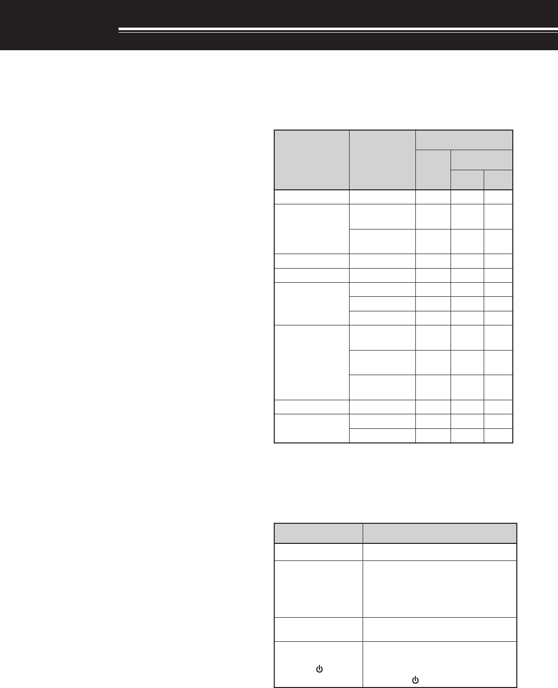
SUPPLIED ACCESSORIES
After carefully unpacking the transceiver, identify the
items listed in the table below. We recommend you
keep the box and packing material in case you need
to repack the transceiver in the future.
yrosseccA rebmuNtraP
ytitnauQ
A6F-HT E7F-HT
)K( )E( )T(
koohtleBXX-3260-92J111
annetnA
XX-1870-09T )dnab-4( 1––
XX-9870-09T )dnab-3( –11
partSXX-9330-96J111
yrettabnoi-iLXX-9790-90W111
regrahC
XX-7290-80W1––
XX-8290-80W–1–
XX-9290-80W––1
noitcurtsnI launaM
XX-1441-26B )S/E( 111
XX-2441-26B )I/F( –1–
XX-3441-26B )G/D( –1–
ecitoNETT&RXX-7622-95B–11
dracytnarraW XX-9640-64B1––
XX-0130-64B–11
WRITING CONVENTIONS FOLLOWED
The writing conventions described below have
been followed to simplify instructions and avoid
unnecessary repetition.
noitcurtsnI oDottahW
sserP ]YEK[]YEK[ ]YEK[ ]YEK[]YEK[ .esaelerdnasserP YEKYEK YEK YEKYEK .
sserP ]2YEK[+]1YEK[]2YEK[+]1YEK[ ]2YEK[+]1YEK[ ]2YEK[+]1YEK[]2YEK[+]1YEK[ .
dlohdnasserP 1YEK1YEK 1YEK 1YEK1YEK ,nwod
sserpneht 2YEK2YEK 2YEK 2YEK2YEK eraerehtfI. dnasserp,syekowtnahterom litnunrutniyekhcaenwoddloh .desserpneebsahyeklanifeht
sserP ]1YEK[]1YEK[ ]1YEK[ ]1YEK[]1YEK[ ,]2YEK[]2YEK[ ]2YEK[ ]2YEK[]2YEK[ .sserP 1YEK1YEK 1YEK 1YEK1YEK ,yliratnemom
esaeler 1YEK1YEK 1YEK 1YEK1YEK sserpneht, 2YEK2YEK 2YEK 2YEK2YEK .
sserP ][+]YEK[][+]YEK[ ][+]YEK[ ][+]YEK[][+]YEK[ .
,FFOrewopreviecsnartehthtiW dlohdnasserp YEKYEK YEK YEKYEK hctiwsneht, ybrewopreviecsnartehtNO gnisserp ][][][ ][][.)REWOP(

ii
MODELS COVERED BY THIS MANUAL
The models listed below are covered by this manual.
TH-F6A: 144 MHz/ 220 MHz/ 440 MHz FM
Multi-band Portable Transceiver
TH-F7E: 144 MHz/ 430 MHz FM
Dual-band Portable Transceiver
MARKET CODES
K-type: The Americas
E-type: Europe/ Universal type
T-type: United Kingdom
The market code is shown on the carton box.
Refer to the specifications {page xx} for the
information on available operating frequencies within
each market.
NOTICE TO THE USER
One or more of the following statements may be
applicable for this equipment.
FCC WARNING
This equipment generates or uses radio frequency energy.
Changes or modifications to this equipment may cause harmful
interference unless the modifications are expressly approved in
the instruction manual. The user could lose the authority to
operate this equipment if an unauthorized change or
modification is made.
INFORMATION TO THE DIGITAL DEVICE USER REQUIRED
BY THE FCC
This equipment has been tested and found to comply with the
limits for a Class B digital device, pursuant to Part 15 of the
FCC Rules. These limits are designed to provide reasonable
protection against harmful interference in a residential
installation.
This equipment generates, uses and can generate radio
frequency energy and, if not installed and used in accordance
with the instructions, may cause harmful interference to radio
communications. However, there is no guarantee that the
interference will not occur in a particular installation. If this
equipment does cause harmful interference to radio or
television reception, which can be determined by turning the
equipment off and on, the user is encouraged to try to correct
the interference by one or more of the following measures:
•
Reorient or relocate the receiving antenna.
•
Increase the separation between the equipment and receiver.
•
Connect the equipment to an outlet on a circuit different from
that to which the receiver is connected.
•
Consult the dealer for technical assistance.
1
PREPARATION
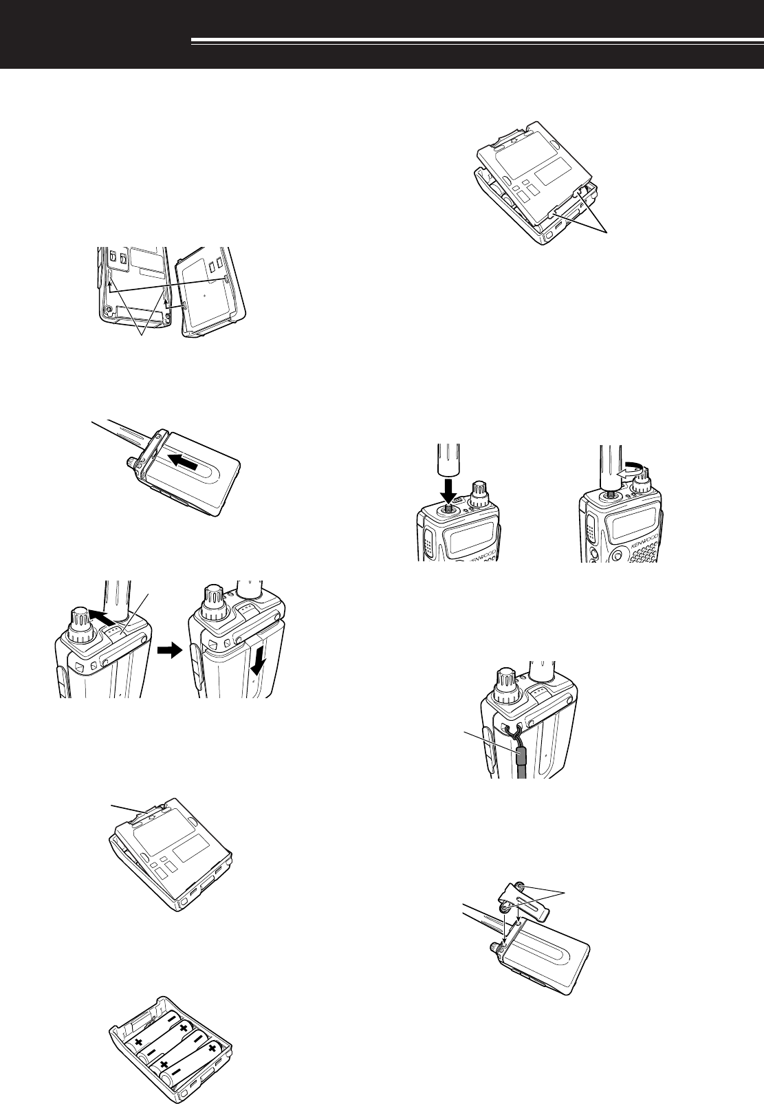
INSTALLING THE Li-ion BATTERY PACK
Note: Because the battery pack is provided uncharged, you must
charge the battery pack before using it with the transceiver. To
charge the battery pack, refer to “CHARGING THE Li-ion BATTERY
PACK” {page 2}.
1Position the two grooves on the edge and two
hooks at the bottom of the battery pack over the
corresponding guides on the back of the
transceiver.
2Slide the battery pack along the back of the
transceiver until the release latch on the top of the
transceiver locks the battery pack in place.
3To remove the battery pack, pull the release latch
on top, then slide the battery pack down.
INSTALLING ALKALINE BATTERIES
1To open the battery case (BT-13), push the locking
tab in, then pull the cover back.
2Insert (or remove) four AA (LR6) alkaline batteries.
• Be sure to match the battery polarities with
those marked in the bottom of the battery case.
3Align the two tabs on the battery case cover, then
close the cover until the locking tabs click.
4 To install the battery case onto (or remove it from)
the transceiver, follow steps 1 to 3 of
“INSTALLING THE Li-ion BATTERY PACK”
{above}.
INSTALLING THE ANTENNA
Hold the base of the supplied antenna, then screw
the antenna into the connector on the top panel of the
transceiver until secure.
a
ATTACHING THE HAND STRAP
If desired, you can attach the supplied hand strap to
the transceiver.
INSTALLING THE BELT CLIP
You can install the supplied belt clip to the transceiver
tightening the 2 supplied screws.
Tab
Screws
Strap
Tabs
Grooves
Latch
2
1 PREPARATION
CHARGING THE Li-ion BATTERY PACK
The Li-ion battery pack can be charged after it has
been installed onto the transceiver. The battery pack
is provided uncharged for safety purposes.
1Confirm that the transceiver power is OFF.
• While charging the battery pack, leave the
transceiver power OFF.
2Insert the charger plug into the DC IN jack of the
transceiver.
3Plug the charger into an AC wall outlet.
• Charging starts and “CHARGING” appears.
4It takes approximately 6 hours to charge an empty
PB-42L Li-ion battery. When charging is
complete, “STANDBY” appears; remove the
charger plug from the transceiver DC IN jack.
5Unplug the charger from the AC wall outlet.
◆
Exceeding the specified charge period shortens the useful
life of the Li-ion battery pack.
◆
The provided charger is designed to charge only the
provided PB-42L Li-ion battery pack. Charging other models
of battery packs may damage the charger and battery pack.
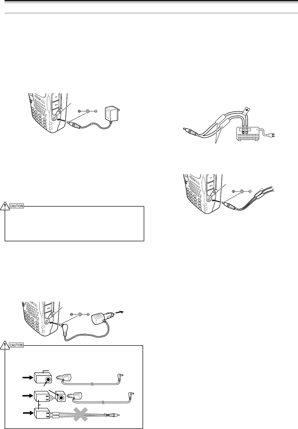
CONNECTING TO A CIGARETTE LIGHTER
SOCKET
To connect the transceiver to the cigarette lighter
socket in your vehicle, use an optional PG-3J
Cigarette Lighter cable.
To connect with an external 24 V power source via a DC-DC
converter, only use the optional PG-3J Cigarette Lighter cable.
Using the PG-2W DC cable in this situation may cause a fire.
PG-2W
24V
12V
24V PG-3J
12V
12V
24V PG-3J
Note: If the input voltage exceeds approximately 18 V, warning
beeps sound and “VOLTAGE ERROR” appears.
CONNECTING TO A REGULATED POWER
SUPPLY
To connect the transceiver to an appropriate
regulated power supply, use an optional PG-2W
DC cable.
1Confirm that the power of both the transceiver and
the power supply are OFF.
2Connect the optional PG-2W DC cable to the
power supply; the red lead to the positive (+)
terminal, and the black lead to the negative (–)
terminal.
3Connect the barrel plug on the DC cable to the DC
IN jack of the transceiver.
Note:
◆
Only use power supplies recommended by your authorized
KENWOOD dealer.
◆
The supply voltage must be between 5.5 V and 16 V to prevent
damaging the transceiver. If input voltage exceeds
approximately 18 V, warning beeps sound and “VOLTAGE
ERROR” appears.
DC IN jack DC 12 V
DC-DC Converter
DC-DC Converter
Fuses
DC IN jack
DC IN jack
Socket
3
YOUR FIRST QSO
FIRST QSO
Are you ready to give your TH-F6A/ TH-F7E a quick
try? Reading this page should get your voice on the
air right away. The instructions below are intended
only for a quick guide. If you encounter problems or
there is something you would like to know more, read
the detailed explanations given later in this manual.
4
35
2
1
678
qPresss and hold [ ] (POWER) briefly to switch
the transceiver power ON.
• Do not press the switch for more than
approximately 2 seconds; the transceiver will
be switched OFF.
• A high pitched double beep sounds and then
“KENWOOD” and “HELLO!!” appears
momentarily. The various indicators and 2
frequencies appear on the LCD.
wPress [A/B] to select the frequency band on top.
• Each time you press [A/B], the “s” icon
moves, indicating which frequency band is
currently selected for operation.
eTurn the VOL control clockwise to the 11 o’clock
position.
rPress [BAND] until you select the amateur radio
band you wish to operate.
tTurn the Tuning control to select the receive
frequency.
• You may further turn the VOL control to adjust
the volume level of the signal.
yTo transmit, hold the transceiver approximately
5 cm (2 inches) from your mouth.
uPress and hold the PTT switch, then speak in your
normal tone of voice.
iRelease the PTT switch to receive.
oRepeat steps y, u and i to continue
communication.
4
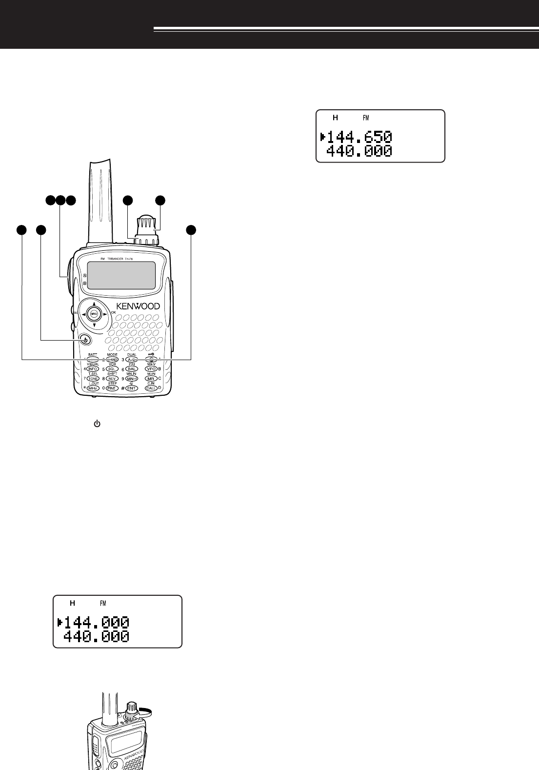
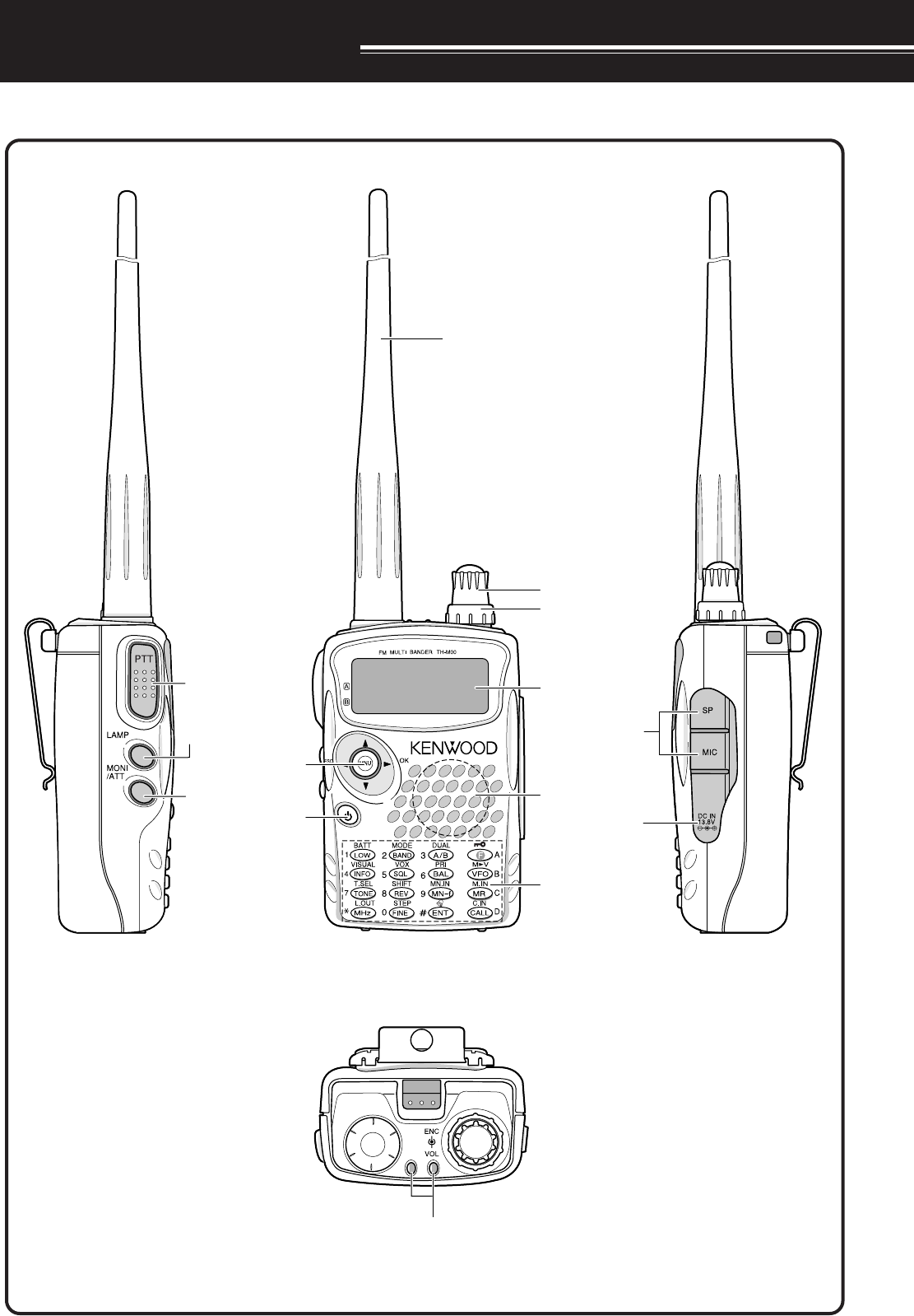
GETTING ACQUAINTED
KEYS AND CONTROLS
A/ B-band status LEDs
Tuning Control
VOL Control
Display
PTT switch
LAMP Key
Antenna
Speaker/ Mic.
Keypad
Power Switch
MONI Key
M
Menu/Cursor
Keys
SP/MIC jack
DC IN jack
5
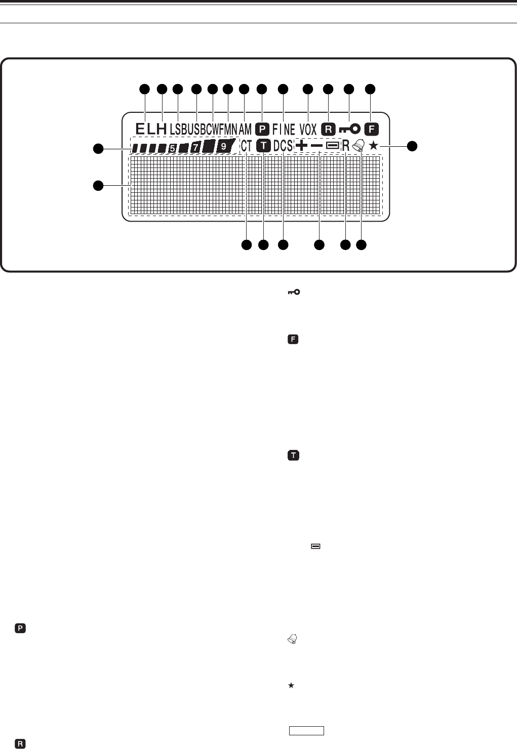
4 GETTING ACQUAINTED
qE L
Appears when the transmit output power is set to Low
(“L”) or Economic Low (“E L”) {pages 7, }.
w H
Appears when the transmit output power is set to
High (“H”) {pages 7, }.
eLSB
Appears when lower side band (LSB) is selected for
B-band {page 36}.
rUSB
Appears when upper side band (USB) is selected for
B-band {page 36}.
tCW
Appears when CW is selected for B-band {page 36}.
yWFM/ FM/ FMN
“WFM” appears when wide FM mode is selected
{page 36}.
“FM” appears when normal FM mode is selected.
“FMN” appears when narrow FM mode is selected
{pages 36, }.
u AM
“AM” appears when AM mode is selected {page 36}.
i
Appears when a priority scan is activated {page 25}.
oFINE
Appears when a fine tuning function is activated.
!0 VOX
Appears when the VOX function is activated
{page xx}.
!1
Appears when the Automatic Simplex Check (ASC) is
activated {page 14}.
!2
Appears when the Key lock function is activated
{page xx}.
!3
Appears when the function key is pressed.
!4
S-meter (RX) and relative output power meter (TX).
!5 CT
“CT” appears when the CTCSS function is activated
{page 28}.
!6
Appears when the Tone function is activated
{page 13}.
!7 DCS
Appears when the DCS function is activated
{page 29}.
!8 +/ –/
Appears when the repeater shift function is activated
{page 12}.
!9 R
Appears when the Reverse shift function is activated
{page 14}.
@0
Appears when the Tone Alert function is activated
{page xx}.
@1
Appears when the displayed memery channel has
been locked out {page 27}.
@2
Full dot-matrix display (76 x 16 dots). It displays
various informations, such as the operating
frequencies, menu settings, and etc.
DISPLAY
14
1
15
21
22
2 3 4 5 6 7 8 9 10 11 12 13
16 17 18 19 20
6
4 GETTING ACQUAINTED
BASIC OPERATION
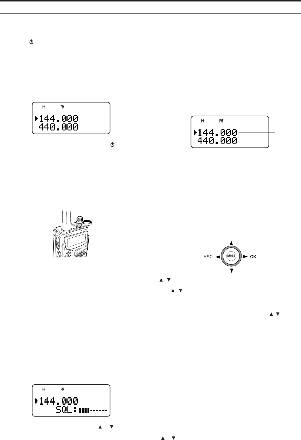
SWITCHING POWER ON/ OFF
1Press [ ] (POWER) briefly to switch the
transceiver power ON.
• Do not press the key for more than
approximately 2 seconds; the transceiver will
be switched OFF.
• Upon power up, a high pitched double beep
sounds, followed by the frequencies and other
indicators.
2To switch the transceiver OFF, press [ ]
(POWER) again.
• When you turn the transceiver OFF, a low
pitched double beep sounds.
ADJUSTING VOLUME
Turn the VOL control clockwise to increase the audio
output level and counterclockwise to decrease the
output level.
• If you are not receiving a signal, press and hold
[MONI] to unmute the speaker, then adjust the
VOL control to a comfortable audio output level.
ADJUSTING SQUELCH
The purpose of the Squelch is to mute the speaker
when no signals are present. With the squelch level
correctly set, you will hear sound only while actually
receiving signals. The higher the selected squelch
level, the stronger the signals must be, to receive.
The appropriate squelch level depends on the
ambient RF noise conditions. You can configure
independent threshold squelch levels for the A-band
and B-band.
1Press [SQL].
• The current SQL level appears.
2Turn the Tuning control or press [ ]/ [ ] to adjust
the level.
• Select the level at which the background noise
is just eliminated when no signal is present.
• The higher the level, the stronger the signals
must be, to receive.
• 6 different levels can be set (OPEN: unmuted ~
|| || || || || || : maximum).
3Press [ss
ss
s] or [MNU] to store the new settings or
press [tt
tt
t] to cancel without changing the current
setting.
SELECTING A BAND
By default, two frequencies are displayed on the
LCD. The frequency on top is called the A-band. The
bottom frequency is called the B-band.
Press [A/B] to select the A-band or B-band for
operation. Each time you press [A/B], the “s” icon
moves, indicating which band is currently selected for
operation. Usually, select the A-band to operate the
amateur band and select the B-band to receive the
various broadcasting stations, such as AM, FM, TV
(audio only) or another amateur band {page 35}.
CURSOR KEYS
This transceiver has a 4-way cursor key with a MENU
(“MNU”) key in the center.
/ keys
The / keys function in the same way as the
Tuning control. These keys change the frequencies,
memory channels, and other selections.
Note: You can use the Tuning control in place of the / keys for
most of the controls.
s/ OK key
Press to move to the next step or complete the
setting in various modes, such as Menu mode,
CTCSS frequency selection, and DCS code selection.
t/ ESC key
Press to move back or cancel the entry in various
modes, such as Menu mode, CTCSS frequency
selection, and direct frequency entry.
MNU key
Press to enter the Menu mode.
In Menu mode, you can select the desired menu
number by turning the Tuning control or pressing
[]/ [ ].
A-band
B-band
7
4 GETTING ACQUAINTED
TRANSMITTING
1To transmit, hold the transceiver approximately
5 cm (2 inches) from your mouth, then press and
hold the PTT switch and speak into the
microphone in your normal tone of voice.
• The status LED on the top panel lights red and
bar-graph meter appears.
• If you press [PTT] while you are outside of the
transmission coverage, a high pitched error
beep sounds.
2When you finish speaking, release the PTT switch.
Note: If you transmit countinuously for more than 10 mintues, the
internal time-out timer generates a warning beep and the transceiver
stops transmitting. In this case, release the PTT switch and let the
transceiver cool down for a while, then press the PTT switch again to
resume transmitting {page xx}.
■Selecting Output Power
Selecting lower transmission power is the best way to
reduce the battery consumption, if communication is
still reliable. You can configure different power levels
for transmission {page xx}.
Press [LOW].
• Each time you press [LOW], the indicator cycles
between “H” (high), “L” (low), and “EL” (economic
low).
Note:
◆
You can store different output power setting for the A and B-band.
When you change the output power, it is reflected to all available
amateur bands for A or B-band.
SELECTING A FREQUENCY
■VFO mode
This is the basic mode for changing the operating
frequency. Turn the Tuning control clockwise to
increase the frequency. Turn the Tuning control
counterclockwise to decrease the frequency. Or,
press [ ]/ [ ] to change the frequency.
If the desired operating frequency is far away from
the current frequency, it is quicker to use the MHz
tuning mode.
1Press [MHz].
• A MHz digit blinks.
2Turn the Tuning control or press [ ]/[ ] to select
the desired MHz digit.
3After selecting the desired MHz digit, press [MHz]
to exit the mode and return to normal tuning
mode.
4You may further adjust the frequency using the
Tuning control or [ ]/[ ].
■Direct Frequency Entry
In addition to turn the Tuning control or press [ ]/[ ],
there is another way of selecting the frequency.
When the desired frequency is far away from the
current frequency, you can directly enter a frequency
from the numeric keypad.
1Press [VFO].
• You must be VFO mode to make the direct
frequency entry.
2Press [ENT].
• “– – – – – – ” appears.
3Press the numeric keys ([0] to [9]) to enter your
desired frequency. [MHz] can be used to
complete the MHz digits entry.
• Pressing [ENT] fills the remaining digits (the
digits you did not enter) with 0 and completes
the entry.
• To select 145.000 MHz for example, press [1],
[4], [5] then press [ENT] to complete the entry.
Example 1 (100 MHz < f < 1000 MHz)
To enter 438.320 MHz:
Key in Display
[ENT] – –– –––
[4], [3], [8] 4 3 8. – – –
[3], [2], [0] 4 3 8. 3 2 0
Note: You do not have to press [MHz] when you are entering 3-
digit MHz number.

8
4 GETTING ACQUAINTED
Example 2
To enter 439.000 MHz:
Key in Display
[ENT] ––– –––
[4], [3], [9] 4 3 9. – – –
[ENT] 4 3 9. 0 0 0
Example 3 ( f > 1000 MHz)
To enter 1250.500 MHz (B-band only):
Key in Display
[ENT] ––– –––
[1], [2], [5], [0] 12 5 0. – – –
[5] 12 5 0. 5 – –
[ENT] 12 5 0. 5 0 0
Example 4 (f < 100 MHz)
To enter 10.500 MHz (B-band only):
Key in Display
[ENT] ––– –––
[1], [0] 1 0 – – – –
[MHz] 1 0. – – –
[5] 1 0. 5 – –
[ENT] 1 0. 5 0 0 0
Note: When pressing the last [ENT], the FINE tuning function is
automatically activated for 10.5000 MHz.
Example 5
To enter 810 kHz (B-band only):
Key in Display
[ENT] ––– –––
[0] 0 – – – – –
[MHz] 0. – – –
[8], [1], [0] 0. 8 1 0
Note:
◆
If the entered frequency does not match the current frequency
step size, the frequency is automatically rounded up or down to
the next available frequency.
◆
When the desired frequency cannot be entered exactly, check
whether the FINE function is ON or not and confirm the
frequency step size {page xx}.
◆
Some frequency ranges are blocked, due to government
regulations. Refer to the specifications for the TX/ RX coverage.
◆
If you turn the Tuning control or press [ ]/ [ ] while entering
the frequency, the transceiver clears the entry and recovers the
previous frequency and mode.
9
MENU SETUP
WHAT IS A MENU?
Many functions on this transceiver are selected or
configured via a software-controlled Menu, rather
than through the physical controls of the transceiver.
Once familiar with the Menu system, you will
appreciate the versatility it offers. You can customize
the various timings, settings, and programming
functions on this transceiver to meet your needs
without using many controls and switches.
MENU ACCESS
1Press [MNU].
• The Menu No. and setting appear on the
display, along with a brief explanation of the
Menu No.
2Turn the Tuning control or press [ ]/ [ ] to select
your desired Menu No.
• As you change the Menu No., a brief
explanation of each Menu No. appears.
3Press [ss
ss
s] or [MNU] to configure the parameter of
the currently selected Menu No.
4Turn the Tuning control or press [ ]/ [ ] to select
your desired parameter.
5Press [ss
ss
s] or [MNU] to store the setting.
Otherwise, press [tt
tt
t] or [PTT] to cancel.
MENU FUNCTION LIST
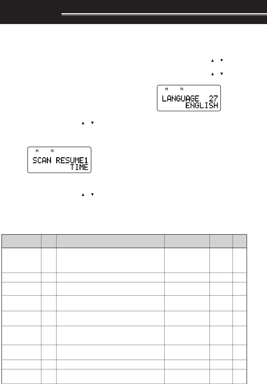
SELECTING A MENU LANGUAGE
You can select either English or Japanese (katakana)
for the menu description. To switch the language:
1Press [MNU].
2Turn the Tuning control or press [ ]/ [ ] to select
Menu No. 27.
3Turn the Tuning control or press [ ]/ [ ] to select
either “ENGLISH” or “JAPANESE”.
4Press [ss
ss
s] or [MNU] to store the setting.
Otherwise, press [tt
tt
t] or [PTT] to cancel.
• When you select “JAPANESE” in step 3 and
press [ss
ss
s] or [MNU], all Menu explanations are
displayed in Japanese (katakana). To return to
English mode, repeat step 1 and 2 {above} to
access Menu No. 27, then select “EIGO”.
Press [ss
ss
s] or [MNU] to display the Menu mode
in English.
Note: The menu language selection does not affect any other
modes, such as memory name or DTMF name.
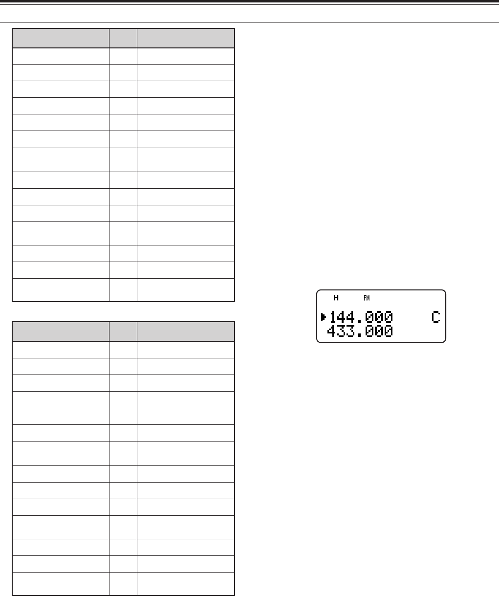
yalpsiDehtnO
uneM .oN
noitcnuF snoitceleS tluafeD .feR gaPe
EMUSERNACS1
dohtememusernacS edomdetarepO-emiT:EMIT edomdetarepO-reirraC:REIRRAC edompotsdnakeeS:KEES
/REIRRAC/EMIT KEES EMIT72
KNILPRG.M2 noitarugifnockniLpuorGyromeM76543210skniLoN42
DOHTEMRM3 noitidnocllaceRyromeM /SDNABLLA DNABTNERRUC LLA SDNAB 61
OFVGORP4 egnarycneuqerfOFVelbammargorP—
eeS ecnerefeR egaP
TESFFOOTUA5 noitcnuftesffOretaepeRotuAFFO/NONO31
TESFFO6 ycneuqerftesfforetaepeR zHM59.95~00.0 fospetsni zHM50.0
eeS ecnerefeR egaP
21
ELBANEENUT7 syekehtnehwlortnocgninuTehtfoesutimreP dekcolera FFO/NOFFO
TIBIHNIXT8 noissimsnartehttibihnIFFO/NOFFO
KCAJPS/CIM9 noitcnufkcajPS/CIMehttceleSCP/CNT/PS/CIMPS/CIM

10
6 MENU SETUP
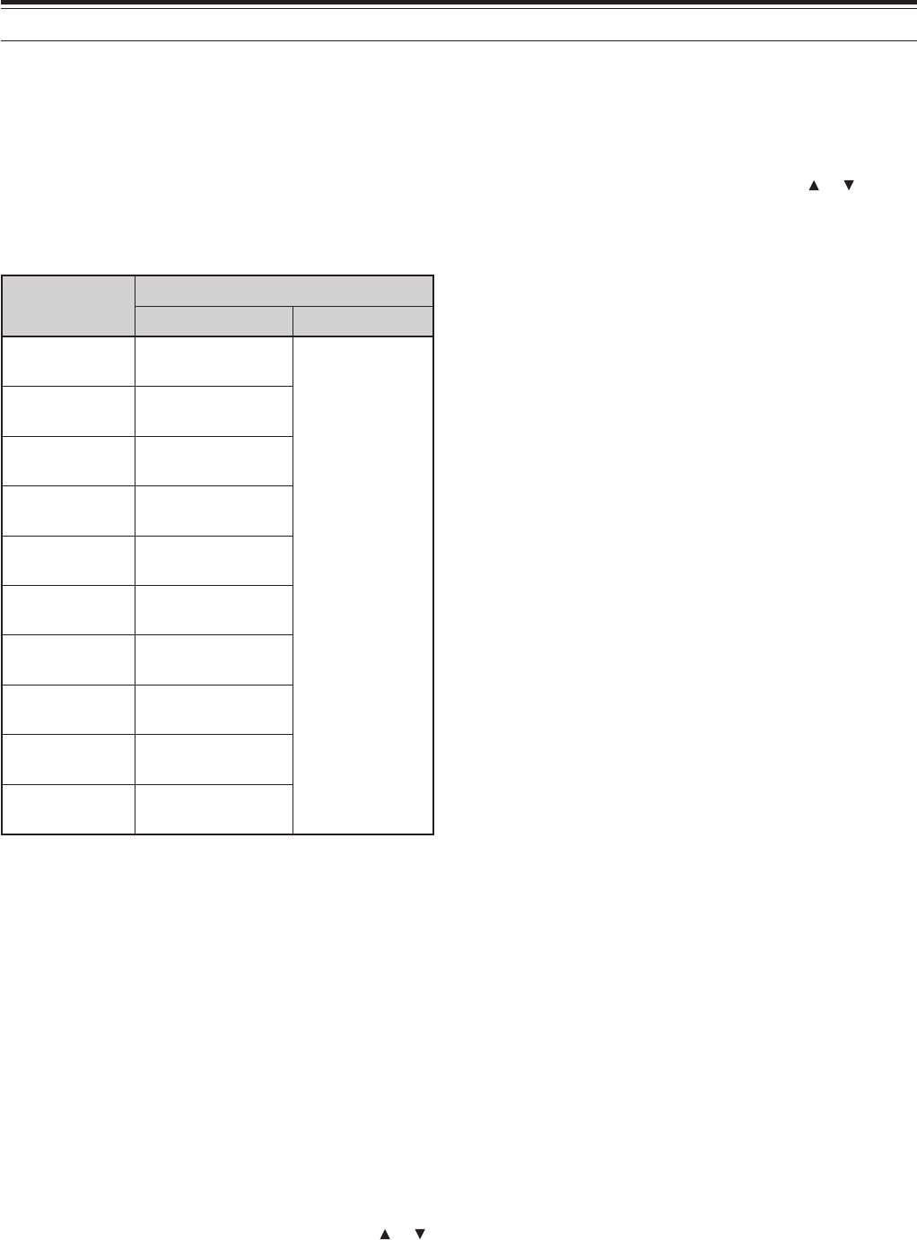
yalpsiDehtnO uneM .oN noitcnuF snoitceleS tluafeD .feR gaPe
EROTSFMTD01seiromemFMTDnisrebmunFMTDerotS—ataDoN13
DPSFMTD11deepsnoissimsnartenotFMTDWOLS/TSAFTSAF23
DLOHFMTD21neewtebsdnoces2rofnoissimsnartehtdloH seirtneyekFMTD FFO/NOFFO13
ESUAPFMTD31FMTDgnittimsnartelihwnoitarudesuapehT senot
/005/052/001 /0051/0001/057 sm0002 sm00523
KCOLFMTD41syekhtiwnoissimsnartFMTDelbasiDFFO/NOFFO33
GSMNO-RWP51egassemno-rewoPsretcarahc8
!!OLLEH
TSARTNOC61tsartnocyalpsidDCL mumixam:61~muminim:1 61~1804
REVASTAB71doirepffo-tuhsreviecerrevasyrettaB /6.0/4.0/2.0/FFO /0.3/0.2/0.1/8.0 .ces0.5/0.4 .ces0.1
OPA81noitcnufffOrewoPcitamotuA.nim06/03/FFO.nim0304
PEEBYEK91noitcnufpeeBFFO/NONO04
YSUBnoXOV02sireviecerehtnehwnoissimsnartXOVwollA ysub FFO/NOFFO
NIAGXOV12ytivitisnesniagXOVehtteS evitisnestsom:9~evisitnestsael:0 9~04
YALEDXOV22emityaledXOVehttsujdA /003/002/001 /0051/0001/005 sm0003 sm005
YEKLLAC32yekLLACehtrofnoitcnufatceleSzH0571/LLAC
LLAC
)A6F-HT(
zH0571
)E7F-HT(
91
DLOH057142sienotzH0571anehwsutatsXTehtdloH dettimsnart FFO/NOFFO31
TFIHSTAEB52ycneuqerfkcolcUPClanretniehttfihSFFO/NOFFO04
TNARAB62zHM0.7wolebannetnarablanretninaelbanE /ELBANE ELBASID
ELBANE
04
EGAUGNAL72egaugnalunemehttceleS /HSILGNE ESENAPAJ
HSILGNE
9
TEKCAP82deepstekcapCNTlanretxenatceleSspb0069/0021spb0021
WORRANMF92noitarepodnabworranMFFFO/NOFFO
?TESER03edomteseratceleS /TESEROFV/ON /TESERUNEM TESERLLUF ON

11
6 MENU SETUP
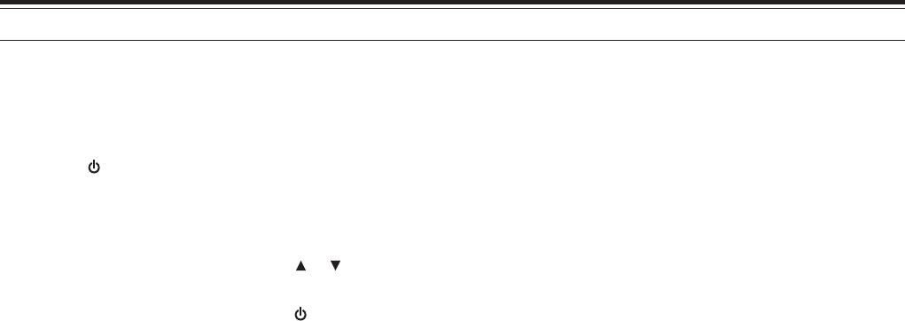
yalpsiDehtnO .oNuneM snoitceleS tluafeD gaP.feRe
OPA81setunim06/03/FFO.nim03
TESFFOOTUA5 NO/FFONO
TNARAB62ELBASID/ELBANEELBANE
REVASTAB71sdnoces0.5/0.4/0.3/0.2/0.1/8.0/6.0/4.0/2.0/FFO.ces0.1
TFIHSTAEB52NO/FFOFFO
YEKLLAC32zH0571/LLAC
LLAC /)E7F-HT( zH0571 )A6F-HT(
TSARTNOC6161~1804
DLOHFMTD21NO/FFOFFO
KCOLFMTD41NO/FFOFFO
ESUAPFMTD31sm0002/0051/0001/057/005/052/001sm005
DPSFMTD11WOLS/TSAFTSAF
EROTSFMTD01— atadoN
WORRANMF92NO/FFOFFO
PEEBYEK91NO/FFONO
EGAUGNAL72ESENAPAJ/HSILGNEHSILGNE
KCAJPS/CIM9 CP/CNT/CIM/PSCIM/PS
DOHTEMRM3 DNABTNERRUC/SDNABLLA LLA SDNAB
KNILPRG.M2 76543210kniLoN
TESFFO6 zHM50.0fospetsnizHM59.95~00.0 /zHM06.0 zHM6.1 )A6F-HT(
TEKCAP82spb0069/0021spb0021
OFVGORP4 egarevocreviecermumixaM—
GSMNO-RWP51sretcarahcciremun-ahpla8!!OLLEH
?TESER03TESERLLUF/TESERUNEM/TESEROFV/ONON
EMUSERNACS1 KEES/REIRRAC/EMITEMIT
ELBANEENUT7 NO/FFOFFO
TIBIHNIXT8 NO/FFOFFO
YALEDXOV22sm0003/0051/0001/005/003/002/001sm005
NIAGXOV129~04
YSUBnoXOV02NO/FFOFFO
DLOH057142NO/FFOFFO
ALPHABETICAL FUNCTION LIST
12
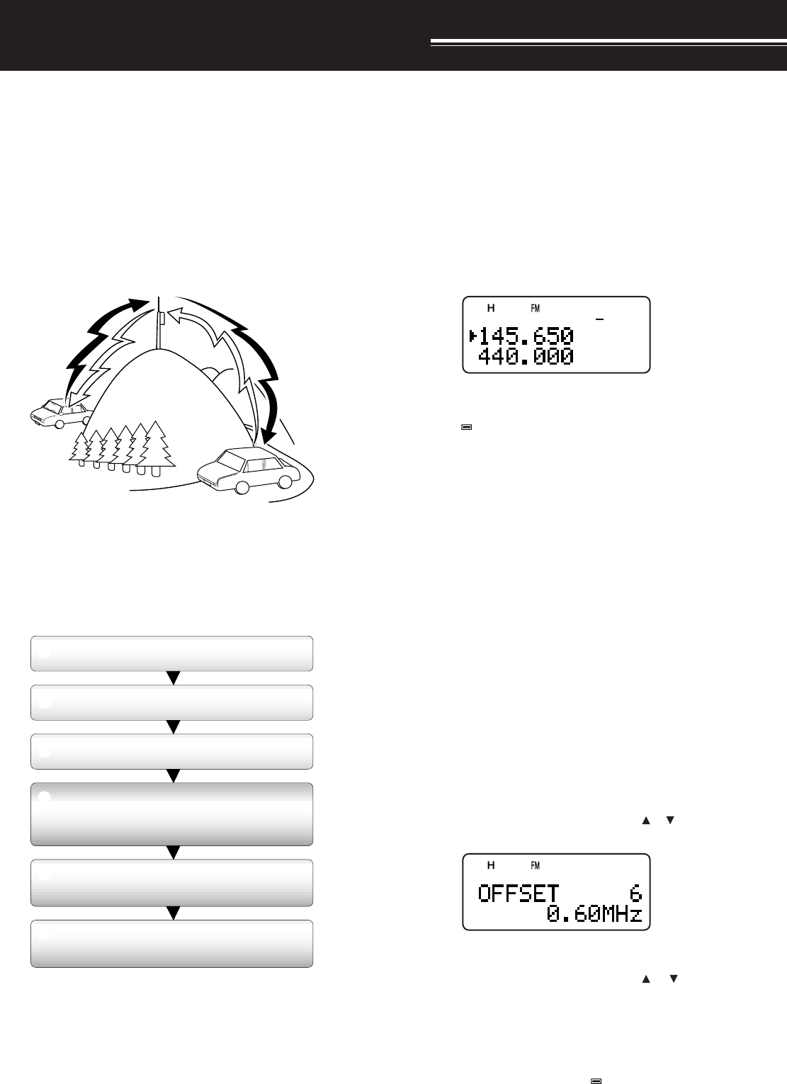
OPERATING THROUGH REPEATERS
Repeaters, which are often installed and maintained
by radio clubs, are usually located on mountain tops
or other elevated locations. Generally they operate at
higher ERP (Effective Radiated Power) than a typical
station. This combination of elevation and high ERP
allows communications over much greater distances
than communications without using repeaters.
Most repeaters use a receive and transmit frequency
pair with a standard or non-standard offset (odd-split).
In addition, some repeaters must receive a tone from
the transceiver to allow it to access. For details,
consult your local repeater reference.
Offset Programming Flow
If you store the above data in a memory channel, you
need not reprogram every time. See “MEMORY
CHANNELS” {page 15}.
PROGRAMMING OFFSET
First select an amateur radio repeater downlink
frequency on the A-band or B-band as described in
“SELECTING A FREQUENCY” {page 7}.
■Selecting Offset Direction
Select whether the transmit frequency will be
higher (+) or lower (–) than the receive frequency.
Press [F], [REV] to select the offset direction.
• “+” or “–” appears, indicating which offset
direction is selected.
• To program –7.6 MHz offset on the TH-F7E
(430 MHz only), repeatedly press [F], [REV]
until “ ” appears.
If the offset transmit frequency falls outside the
allowable range, transmitting is inhibited. Use one
of the following methods to bring the transmit
frequency within the band limits:
• Move the receive frequency further inside the
band.
Note: While using an odd-split memory channel or transmitting,
you cannot change the offset direction.
■Selecting Offset Frequency
To access a repeater which requires an odd-split
frequency pair, change the offset frequency from
the default which is used by most repeaters. The
default offset frequency on the 144 MHz band is
600 kHz (All models); the default on the 430/ 440
MHz band is 5 MHz (TH-F6A) or 1.6 MHz
(TH-F7E); the default on the 220 MHz band is
1.6 MHz (TH-F6A).
1Press [BAND] to select an amateur radio band
you want to change the offset frequency.
2Press [MNU].
3Turn the Tuning control or press [ ]/[ ] to
select Menu No. 6 (OFFSET).
4Press [ss
ss
s] or [MNU].
5Turn the Tuning control or press [ ]/ [ ] to
select the appropriate offset frequency.
• The selectable range is from 0.00 MHz to
59.95 MHz in steps of 50 kHz.
6Press [ss
ss
s] or [MNU] to store the setting.
TH-F7E Only: If you have selected “ ” for the offset direction,
you cannot change the default (–7.6 MHz) offset frequency.
Note: After changing the offset frequency, the new offset
frequency will also be used by Automatic Repeater Offset.
TX: 144.725 MHz
TX tone: 88.5 Hz
RX: 145.325 MHz TX: 144.725 MHz
TX tone: 88.5 Hz
RX: 145.325 MHz
Select a band.
q
w
e
r
t
y
Select a receive frequency.
Select an offset direction.
Select an offset frequency.
(Only when programming odd-split
repeater frequencies)
Activate the Tone function.
(If necessary)
Select a tone frequency.
(If necessary)
13
5 OPERATING THROUGH REPEATERS
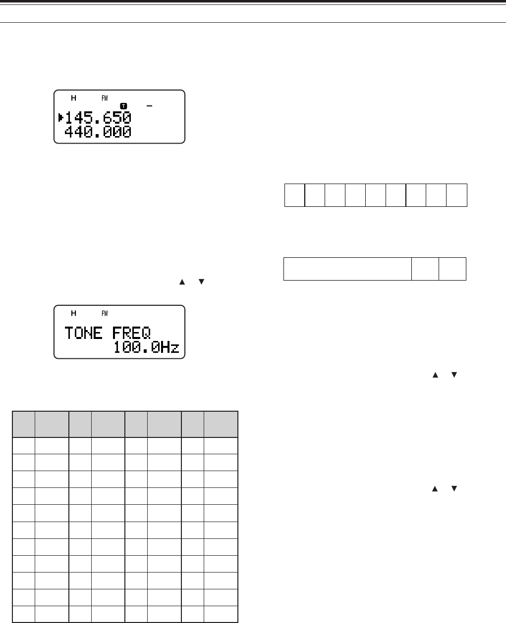
■Activating Tone Function
Press [TONE] to switch the Tone function ON (or
OFF).
• “T” appears when the Tone function is ON.
Note: You cannot use the Tone and CTCSS/ DCS functions at
the same time. Switching the Tone function ON after activating
the CTCSS deactivates the CTCSS/ DCS function.
TH-F7E Only: When you access repeaters that require 1750 Hz
tones, you need not activate the Tone function. Press [CALL]
without pressing the PTT switch to transmit a 1750 Hz tone
(default setting).
■Selecting a Tone Frequency
1While the Tone function is ON, press [F],
[TONE].
2Turn the Tuning control or press [ ]/ [ ] to
select the desired tone frequency.
3Press [ss
ss
s] or [MNU] to complete the setting.
Available Tone frequencies
.oN .qerF )zH( .oN .qerF )zH( .oN .qerF )zH( .oN .qerF )zH(
100.76214.79323.141435.602
203.96310.001422.641537.012
309.17415.301524.151631.812
404.47512.701627.651737.522
500.77619.011722.261831.922
607.97718.411829.761936.332
705.28818.811928.371048.142
804.58910.321039.971143.052
905.88023.721132.681241.452
015.19128.131238.291
118.49225.631335.302
Note: 42 different tones are available for TH-F6A/ TH-F7E.
These 42 tones includes 37 EIA standard tones and 5 non-
standard tones.
TH-F7E only:
◆
To transmit a 1750 Hz tone, simply press [CALL] without
pressing the PTT switch (default setting). Release [CALL] to
quit transmitting. You can also make the transceiver remain
in the transmit mode for 2 seconds after releasing [CALL]; a
1750 Hz tone is not continuously transmitted. Access Menu
No. 24 (1750 HOLD) and select “ON”.
◆
If you desire to assign [CALL] for recalling the Call channel
in place of transmitting the 1750 Hz tone, access Menu No.
23 (CALL KEY) and select “CALL”.
AUTOMATIC REPEATER OFFSET
This function automatically selects an offset direction,
according to the frequency that you select on the
144 MHz and 220 MHz (TH-F6A only) bands. The
transceiver is programmed for offset direction as
shown below. To obtain an up-to-date band plan for
repeater offset direction, contact your national
Amateur Radio association.
TH-F6A (U.S.A. and Canada)
This complies with the standard ARRL band plan.
+–
–– +S
S
SS
144.0 145.5 146.4 147.0 147.6
145.1 146.0 146.6 147.4 148.0 MHz
S: Simplex
TH-F7E (Europe/ Others)
S
S
S: Simplex
–
144.0 146.0 MHz145.8145.6
Note: Automatic Repeater Offset does not function when Reverse is
ON. However, pressing [REV] after Automatic Repeater Offset has
selected an offset (split) status, exchanges the receive and transmit
frequencies.
1Press [MNU].
2Turn the Tuning control or press [ ]/ [ ] to select
Menu No. 5 (AUTO OFFSET).
3Press [ss
ss
s] or [MNU].
4Turn the Tuning control or press []/ [ ] switch
the function ON or OFF.
5Press [ss
ss
s] or [MNU] to store the setting.
5 OPERATING THROUGH REPEATERS
14
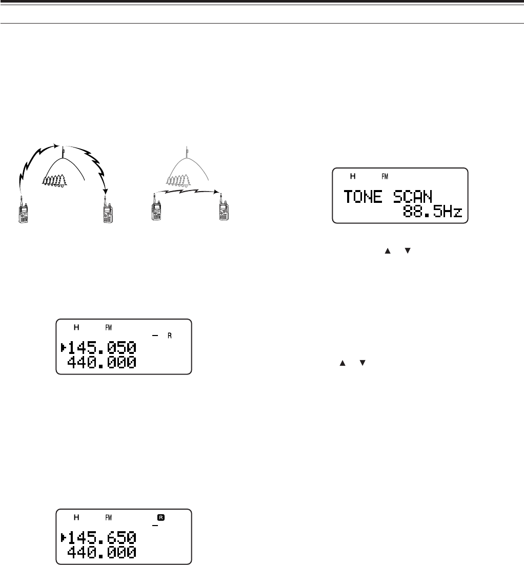
REVERSE FUNCTION
The reverse function exchanges a separate receive
and transmit frequency. So, while using a repeater,
you can manually check the strength of a signal that
you receive directly from the other station. If the
station’s signal is strong, both stations should move
to a simplex frequency and free up the repeater.
To swap the transmit and receive frequencies:
Press [REV] to switch the Reverse function ON (or
OFF).
• “R” appears when the function is ON.
AUTOMATIC SIMPLEX CHECK (ASC)
While using a repeater, the ASC function periodically
checks the strength of a signal that you are receiving
directly from the other station. If the station’s signal is
strong enough to allow direct contact without a
repeater, “R” indicator on the display starts blinking.
Press [REV] (1 s) to switch the function ON.
• “R” appears when the function is ON.
• While direct contact is possible, “R” icon blinks.
• To quit the function, press [REV] momentarily.
Note:
◆
Pressing the PTT switch causes “R” icon to quit blinking.
◆
ASC does not function if your transmit and receive frequencies
are the same (simplex operation).
◆
ASC does not function while scanning.
◆
Activating ASC while using Reverse switches Reverse OFF.
◆
If you recall a memory channel or the Call channel that contains
a Reverse ON status, ASC is switched OFF.
◆
ASC causes received audio to be momentarily intermitted every
3 seconds.
TONE FREQ. ID SCAN
This function scans through all tone frequencies to
identify the incoming tone frequency on a received
signal. You may use the function to find which tone
frequency is required by accessing your local
repeater.
1While the Tone function is ON, press [F], [TONE]
(1 s) to start the Tone Freq. ID scan.
• When the transceiver receives the signal, the
scan starts.
• To reverse the scan direction, turn the Tuning
control or press []/ [ ].
• To quit the function, press [PTT] or [tt
tt
t].
•When the tone frequency is identified, a beep
sounds and the identified frequency appears.
2Press [ss
ss
s] to program the identified frequency in
place of the current tone frequency.
• Press [tt
tt
t] if you do not want to program the
identified frequency.
• Press [ ]/ [ ] while the identified frequency is
blinking, to resume scanning.
Note: Some repeaters do not re-transmit the access tone in the
downlink signal. In this case, check the other station’s uplink signal
to detect the repeater access tone.
144.725 MHz
145.325 MHz
144.725 MHz
TX: 144.725 MHz TX: 144.725 MHz TX: 144.725 MHz TX: 145.325 MHz
RX: 145.325 MHz RX: 145.325 MHz RX: 145.325 MHz RX: 144.725 MHz
15
MEMORY CHANNELS
In memory channels, you can store frequencies and
related data that you often use. Then you need not
reprogram those data every time. You can quickly
recall a programmed channel through simple
operation. A total of 400 memory channels are
available for storing the frequencies, modes and
other operating conditions of the A and B-bands.
SIMPLEX & REPEATER OR
ODD-SPLIT MEMORY CHANNEL?
You can use each memory channel as a simplex &
repeater channel or an odd-split channel. Store only
one frequency to use as a simplex & repeater
channel or two separate frequencies to use as an
odd-split channel. Select either application for each
channel depending on the operations you have in
mind.
Simplex & repeater channels allow:
• Simplex frequency operation
• Repeater operation with a standard offset
(if an offset direction is stored)
Odd-split channels allow:
• Repeater operation with a non-standard offset
Note: Not only can you store data in memory channels, but you can
also overwrite existing data with new data.
The data listed below can be stored in each memory
channel:
retemaraP &xelpmiS retaepeR tilps-ddO
ycneuqerfevieceR seY seY
ycneuqerftimsnarTseY
ycneuqerfenoTseYseY
NOenoTseYseY
ycneuqerfSSCTCseYseY
NOSSCTCseYseY
edocSCDseYseY
NOSCDseYseY
noitceridtesffOseYA/N
ycneuqerftesffOseYA/N
NOesreveRseYA/N
ezispetsycneuqerFseYseY
tuokcollennahcyromeMseYseY
emanlennahcyromeMseYseY
NOgninutENIFseYseY
noitcelesedoMseYseY
Yes: Can be stored in memory.
N/A: Cannot be stored in memory.
STORING SIMPLEX FREQUENCIES OR
STANDARD REPEATER FREQUENCIES
1Press [VFO].
2Turn the Tuning control or press [ ]/ [ ] to select
your desired frequency in the amateur radio
bands.
• You can also directly enter desired frequency
using the keypad {page 7}.
4If storing a standard repeater frequency, select the
following data:
• Offset direction {page 12}
• Tone function, if necessary {page 13}
• CTCSS/ DCS function, if necessary
{pages 28, 29}
If storing a simplex frequency, you may select
other related data (CTCSS or DCS settings, etc.).
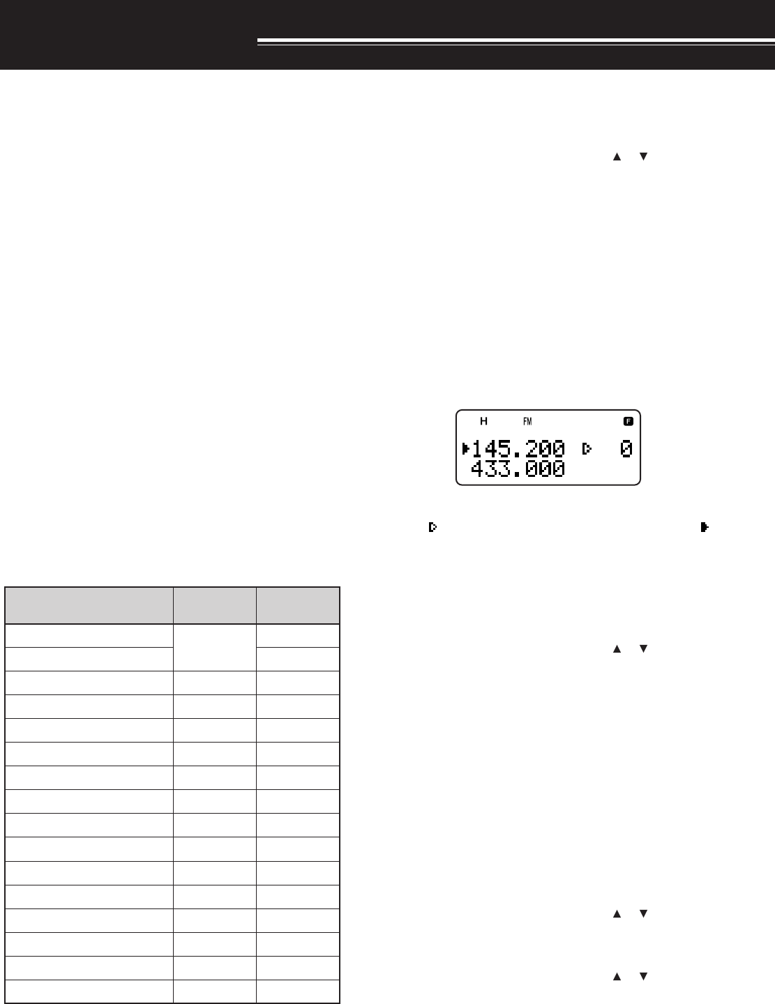
5Press [F].
• A memory channel number appears and blinks.
•“ ” indicates the current channel is empty; “ ”
appears if the channel contains data.
• Memory channel number “L0”/ “U0” ~ “L9”/ “L9”
{page 23}, “I-0” ~ “I-9” {page 20}, and “Pr1” and
“Pr2” {page 25} are reserved for other
functions. Do not use these memories to store
the TX/ RX data.
6Turn the Tuning control or press [ ]/ [ ] to select
the memory channel in which you want to store
the data.
7Press [MR] to store the data to the channel.
STORING ODD-SPLIT REPEATER FREQUENCIES
Some repeaters use a receive and transmit frequency
pair with a non-standard offset. If you store two
separate frequencies in a memory channel, you can
operate on those repeaters without programming the
offset frequency and direction.
1Store the desired receive frequency and related
data by following the procedure given for simplex
or standard repeater frequencies, above.
2Turn the Tuning control or press [ ]/ [ ] to select
the desired transmit frequency.
3Press [F], [MR].
4Turn the Tuning control or press [ ]/ [ ] to select
the memory channel you programmed in step 1.
5Press [PTT]+[MR].
• The transmit frequency is stored in the memory
channel.
Note: When you recall an odd-split memory channel, “+” and “–”
appear on the display. To confirm the transmit frequency, press
[REV].
16
8 MEMORY CHANNELS
RECALLING A MEMORY CHANNEL
There are 2 ways of recalling the desired memory
channel.
■Using the Tuning control or / keys
1Press [MR] to enter Memory Recall mode.
• The memory channel used last is recalled.
2Turn the Tuning control or press [ ]/ [ ] to select
your desired memory channel.
• You cannot recall an empty memory channel.
• To restore VFO mode, press [VFO].
Note: If the “CURRENT BAND” is selected for Menu No. 3 (MR
METHOD), only memory channels that have the same band data can
be recalled {see below}.
■Using a Numeric keypad
You can also recall a memory channel by entering a
desired memory channel number with the keypad.
1Select the desired band.
2Press [MR] to enter Memory Recall mode.
3Press [ENT], then enter the channel number using
3 digits.
• For example, to recall channel 12, press [ENT],
[0], [1], [2].
• You can shorten the entry for memory channels
that are less than 100 by pressing [ENT] after
entering the channel number. For example, to
recall memory channel 9, press [ENT], [9],
[ENT].
Note:
◆
You cannot recall an empty memory channel. An error beep
sounds.
◆
When you recall an odd-split memory channel, “+” and “–” appear
on the display. Press [REV] to display the transmit frequency.
◆
After recalling a memory channel, you may program data such as
Tone or CTCSS. These settings, however, are cleared once you
select another channel or the VFO mode. To permanently store
the data, overwrite the channel contents {page 15}.
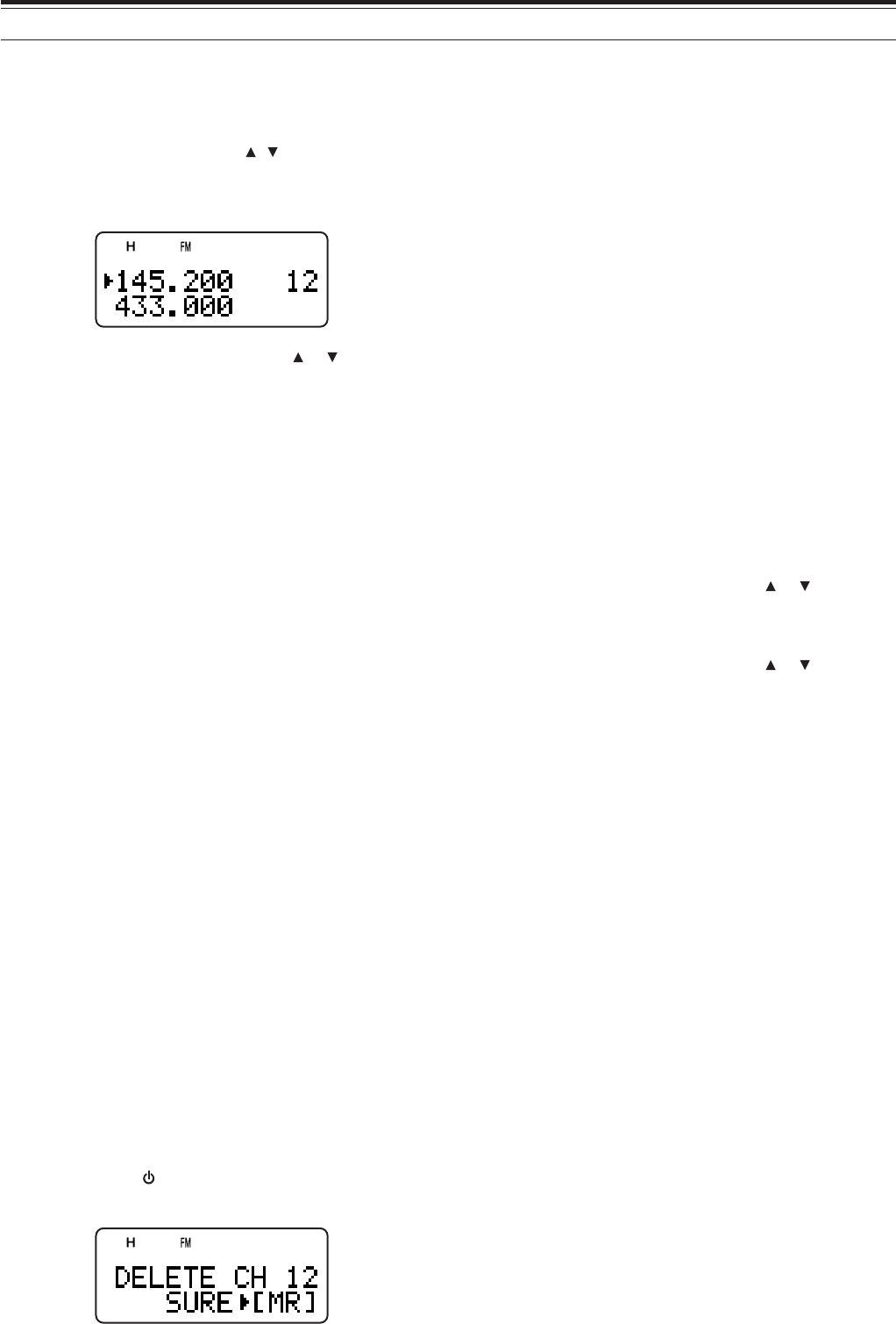
CLEARING A MEMORY CHANNEL
To clear an individual memory channel:
1Recall the memory channel you want to erase.
2Switch the transceiver OFF.
3Press [MR]+ [ ].
• An erase confirmation message appears.
4Press [MR] to erase the channel data.
• The contents of the memory channel are
erased.
• To quit clearing the memory channel, press any
key other than [MR].
Note:
◆
If you clear the information channel data, the data will be set to
the factory default values.
◆
You can also clear the Priority channel data, and L0/U0 ~ L9/U9
data.
MEMORY RECALL MODE
Since the transceiver has more than 400 memory
channels, it sometimes takes time to search for your
desired memory channel. By default, the transceiver
can recall all memory channels when [MR] is
pressed, regardless of the current operating band.
However, you can configure the transceiver to recall
only the memory channels that have the same band
information. For example, when you operate on the
144 MHz band in VFO mode, pressing [MR] recalls
only the memory channels that have 144 MHz band
information. To change the memory recall mode:
1Press [MNU].
2Turn the Tuning control or press []/ [ ] to select
Menu No. 3 (MR METHOD).
3Press [ss
ss
s] or [MNU].
4Turn the Tuning control or press []/ [ ] to select
“CURRENT BAND”.
5Press [ss
ss
s] or [MNU] to store the setting.
When you press [MR] in VFO mode, only memory
channels that have the same band data are recalled.
To return to the default memory recall mode, repeat
step 1 to 5 {above} and select “ALL BANDS” in step
4.
17
8 MEMORY CHANNELS
NAMING A MEMORY CHANNEL
You can name memory channels using up to 8
alphanumeric characters. When you recall a named
memory channel, its name appears on the display in
place of the stored frequency. Names can be call
signs, repeater names, cities, names of people, etc.
1Press [MR] to recall your desired memory
channel.
2Press [F], [MN<->f] to enter memory name input
mode.
• The entry cursor appears.
3Turn the Tuning control or press [ ]/ [ ] to select
the first character.
• You can enter alphanumeric characters plus
special ASCII characters. Refer to the
following table for the available characters.
4Press [ss
ss
s].
• The cursor moves to the next digit.
5Repeat steps 3 and 4 to enter up to 8 digits.
• Pressing [ss
ss
s] after selecting the 8th digit
completes the programming.
• To complete programming after entering less
than 8 digits, press [ss
ss
s] twice.
• Press [tt
tt
t] to move the cursor back.
• Pressing [F] deletes the character at the cursor
position.
You can also use the keypad to enter alphanumeric
characters, in step 3. For example, each press of
[2] sets the entry as a, b, c, 2, A, B, C, and then back
to a. Press [0] to enter a space or 0.
After storing a memory name, pressing [MN<->f]
switches the display between the memory name and
the frequency.
Note:
◆
You can also name the DTMF memory channels {page 31} and
Information Channels {page 20} but you cannot name the Call
channel {page 19}.
◆
You cannot assign a memory name to a channel that does not
contain data.
◆
You can overwirite stored names by repeating steps 1 to 5.
◆
The stored name is erased when you clear the memory channel
data.
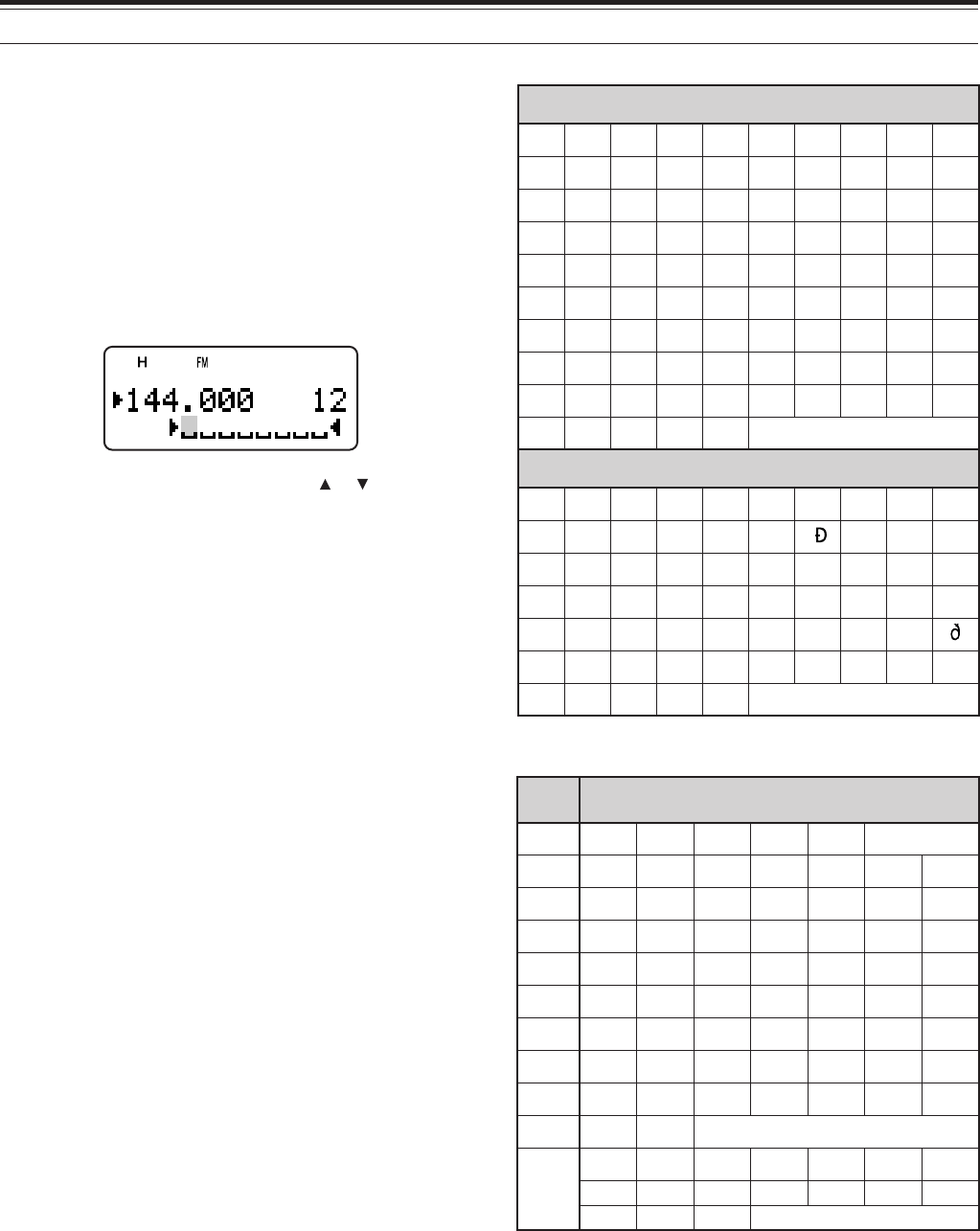
Available characters using the numeric keypad
Available characters using the Tuning control
FMTD yek sretcarahcelbaliavA
1qz1QZ
2abc2ABC
3def3DEF
4ghi4GHI
5jkl5JKL
6mno6MNO
7 p r s 7PRS
8 tuv8TUV
9wxy9WXY
0ecaps0
#
?! ' .,–/
&# ( ) <> ;
:"@
ABCDEFGH I J
KLMNOPQRST
UVWX Y Z [
\
]^_
`abcdefghi
j k lmnopqrs
tuvwxyz{ | }
~PS!"#$%&’
()*+,–./01
23456789: ;
<=>?@
ÀÁÂÃÄÅÆÇÈÉ
ÊËÌÍÎÏ ÑÒÓ
ÔÕÖ ØÙÚÛÜ
ߌàáâãäåæ
çèéêëìíîï
ñòóôõöœøùú
ûü Ÿÿ
´
y
ˆ
S
´
Y
ˆ
s
Additional characters for the TH-F7E
Available characters
18
8 MEMORY CHANNELS
MEMORY CHANNEL GROUPS
400 memory channels have been divided into
8 groups of 50. Group 0 contains memory channel
numbers 0 ~ 49, group 1 is 50 ~ 99, group 2 is 100 ~
149, and so on. You can categorize each group to
store similar data, same frequency bands or same
modes for ease of use.
#puorG lennahcyromeM #puorG lennahcyromeM
0puorG94~04puorG942~002
1puorG99~055puorG992~052
2puorG941~0016puorG943~003
3puorG991~0517puorG993~053
RECALLING A MEMORY CHANNEL USING
MEMORY GROUP FUNCTION
It is sometimes a tedious endeavor to scroll through
400 memory channels sequencially. However, using
a Group memory recall function, you can access your
desired memory channel numbers more quickly.
1Press [MR] to enter Memory Recall mode.
2While pressing and holding [LAMP], turn the
Tuning control to select a group.
• Each click of the Tuning control, the lowest
memory channel number of each group is
recalled. For example, if you have the following
memory channels that contain data:
#puorG atadehtniatnoctahtslennahcyromeM
0puorG0201510354
1puorG0516568789
2puorG301111321
3puorG251661
4puorG
5puorG062082
6puorG503223333543
7puorG993
Memory channels 0, 50, 103, 152, 260, 305, 399,
and then 0 are recalled sequencially while
pressing and holding [LAMP].
3Release [LAMP] and turn the Tuning control to
select the desired memory channels within the
selected group.
Note: If you have configured the Menu No. 3 as “CURRENT BAND”
{page 16}, only memory channels that have the same frequency
band are recalled.
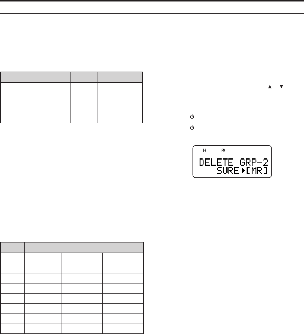
ERASING MEMORY CHANNELS USING MEMORY
GROUP DELETE
Instead of erasing each unnecessary channel one by
one, you can erase an entire group of memory
channels at once. For example, if you erase group 2
memory channels, all the data in memory channels
100 ~ 149 are erased.
1Press [MR].
• Turn the Tuning control or press [ ]/ [ ] to
select a memory channel in the group you want
to erase (for example, memory channel
No. 111, in Group 2).
2Press [ ] (POWER) to turn the transceiver OFF.
3Press [ ] (POWER) + [MHz].
• An erase confirmation message appears.
4Press [MR], [ss
ss
s] or [MNU] to proceed. Otherwise,
press any other key to cancel the erase.
MEMORY TRANSFER
■Memory \ VFO Transfer
After retrieving frequencies and associated data
from Memory Recall mode, you can copy the data
to the VFO. This function is useful, for example,
when the frequency you want to monitor is near
the frequency stored in a memory channel.
1Press [MR], then turn the Tuning control to
recall a desired memory channel.
2Press [F], [MR] to copy the memory channel
data to the VFO.
■Channel \ Channel Transfer
You can also copy channel information from one
memory channel to another. This function is
useful when storing frequencies and associated
data that you temporarily change in Memory
Recall mode.
1Press [MR], then turn the Tuning control to
recall a desired memory channel.
2Press [F].
3Select the memory channel where you would
like the data copied, using the Tuning control.
4Press [MR].
19
8 MEMORY CHANNELS
993~00lennahC a993~00lennahC
ycneuqerfevieceR aycneuqerfevieceR
ycneuqerftimsnarT aycneuqerftimsnarT
ycneuqerfenoT aycneuqerfenoT
noitceridtfihS anoitceridtfihS
ycneuqerfSSCTC aycneuqerfSSCTC
edocSCD aedocSCD
SCD/SSCTC/enoT sutatsFFO/NO aSCD/SSCTC/enoT sutatsFFO/NO
noitceridtesffO anoitceridtesffO
NOesreveR aNOesreveR
ezispetsycneuqerF aezispetsycneuqerF
lennahcyromeM eman alennahcyromeM eman
NOgninutENIF aNOgninutENIF
noitcelesedoM anoitcelesedoM
lennahCyromeM FFO/NOtuokcoL alennahCyromeM FFO/NOtuokcoL
993~0lennahC a2rP,1rP,9U/9L~0U/0L
ycneuqerfevieceR aycneuqerfevieceR
ycneuqerftimsnarT aycneuqerftimsnarT
ycneuqerfenoT aycneuqerfenoT
noitceridtfihS anoitceridtfihS
ycneuqerfSSCTC aycneuqerfSSCTC
edocSCD aedocSCD
SCD/SSCTC/enoT sutatsFFO/NO aSCD/SSCTC/enoT sutatsFFO/NO
noitceridtesffO anoitceridtesffO
NOesreveR aNOesreveR
ezispetsycneuqerF aezispetsycneuqerF
lennahcyromeM eman alennahcyromeM eman
NOgninutENIF aNOgninutENIF
noitcelesedoM anoitcelesedoM
lennahCyromeM NOtuokcoL alennahCyromeM FFOtuokcoL
The tables above illustrate how data is transferred
between memory channels.
CALL CHANNEL
The Call channel can be recalled instantly no
matter what frequency the transceiver is operating
on. For instance, you may use the Call channel as
an emergency channel within your group. In this
case, the Call scan {page 24} will be useful.
The default Call channel frequencies are
144.000 MHz for the 144 MHz band, 223.000 MHz for
220 MHz band (TH-F6A), 430.000 MHz (TH-F7E)/
440.000 MHz (TH-F6A) for the 430/ 440 MHz band.
Each Call channel can be reprogrammed either as a
simplex or odd-split channel.
Note: Unlike memory channels 0 to 399, the Call channel cannot be
cleared. Clearing the Call channel will set it to the factory default
values.
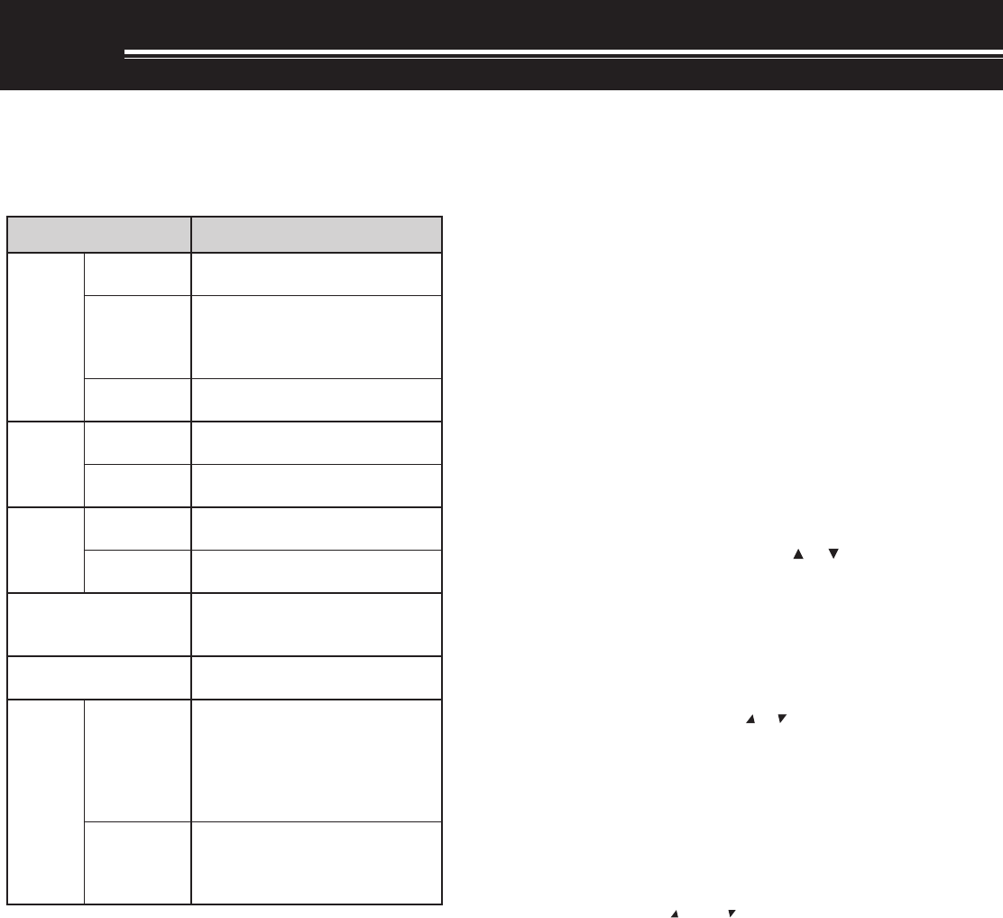
■Recalling the Call Channel
1Press [BAND] to select an amateur radio band.
2Press [CALL] to recall the Call channel for that
operating band.
• The call channel frequency and “C” appear.
• To return to the previous frequency, press
[CALL] again.
■Reprogramming the Call Channel
1Press [BAND] to select your desired amateur
radio band.
2Select your desired frequency and related data
(Tone, CTCSS, DCS, or Shift, etc.).
• When you program the Call channel as an
odd-split channel, select a receive
frequency first.
3Press [F], [CALL].
• The selected frequency and related data are
stored in the Call channel for the selected
band.
To also store a separate transmit frequency,
continue with the following steps.
4Select the desired transmit frequency.
5Press [F].
6Press [PTT]+[CALL].
• The separate transmit frequency is stored in
the Call channel.
Note:
◆
The transmit frequency must be on the same band as the
receive frequency band.
◆
Call channel data is shared between the A and B-band.
◆
Transmit offset status and Reverse status are not stored in
an odd-split Call channel.
◆
To store transceiver configurations other than frequencies,
select the configurations in step 3 not step 5.
20
8 MEMORY CHANNELS
INFORMATION CHANNELS
10 Information channels are available for storing
radio broadcasting service frequencies, such as
weather radio stations and community FM
broadcasting stations. For your conveniences,
pressing [INFO] instantly recalls the Information
channel to B-band. Unlike regular memory channels,
you cannot store a transmit frequency in an
Information channel. The following frequency data is
stored by default.
rebmunlennahC emaNyromeM/edoM/ycneuqerF
A6F-HT E7F-HT
1–I /MF/zHM055.261 REHTAEW
)ytpmE(atadoN
2–I /MF/zHM004.261 REHTAEW
3–I /MF/zHM574.261 REHTAEW
4–I /MF/zHM524.261 REHTAEW
5–I /MF/zHM054.261 REHTAEW
6–I /MF/zHM005.261 REHTAEW
7–I /MF/zHM525.261 REHTAEW
8–I /MF/zHM056.161 REHTAEW
9–I /MF/zHM577.161 REHTAEW
0–I /MF/zHM572.361 REHTAEW
You can revise the default channel data, such as the
receiving frequencies, modes, and memory names.
■Recalling an Information Channel
1Select your desired band.
2Press [INFO] to recall the Information
channels.
• “I–n” appears, where “n” is the Information
channel number from (“0” ~ “9”).
• If the B-band is selected for operation, you
can turn the Tuning control or press []/ [ ]
to select other Information channels.
• To exit the Information channel mode, press
[VFO] or [MR].
Note: If you press [MN<->f], you can display the receiving
frequency in place of the memory name.
■Reprogramming the Information Channel
1Press [VFO].
2Select a desired frequency and mode.
3Press [F].
4Turn the Tuning control or press [ ]/ [ ] to
select the memory channel (I–0 to I–9) in which
you want to store the data.
5Press [MR].
• A long beep sounds and the Information
channel data is now revised.
21
8 MEMORY CHANNELS
CHANNEL DISPLAY
While in this mode, the transceiver displays only
memory channel numbers (or memory names if
stored) instead of frequencies.
1Press [ ] (POWER) + [A/B].
• The transceiver displays the memory channel
number in place of the operating frequencies.
2Turn the Tuning control or press [ ]/ [ ] to select
your desired memory channel number.
To recover normal operation, press [ ] (POWER) +
[A/B] again.
Note:
◆
To enter Channel Display mode, you must have at least one
memory channel that contains the data.
◆
If the memory channel contains the memory name data, the
memory name is displayed in place of the memory channel
number.
22
SCAN
Scan is a useful function for hands-off monitoring of
your favorite frequencies. By becoming comfortable
with all types of Scan, you will increase your operating
efficiency.
This transceiver provides the following types of scans.
epyTnacS esopruP
lamroN nacS
nacSdnaB ehtfodnaberitneehtsnacS detcelesuoyycneuqerf
margorP nacS
deificepsehtsnacS niderotssegnarycneuqerf ~0U/0LslennahcyromeM 9U/9L
nacSzHM nihtiwseicneuqerfehtsnacS egnarzHM1a
yromeM nacS
lennahC-llA nacS ,slennahcyromeMllasnacS 993ot0morf
nacSpuorG yromeMdeificepsehtsnacS spuorglennahc
llaC nacS
OFV dnalennahcllaCehtsnacS ycneuqerfOFVtnerruceht
yromeM lennahC dnalennahcllaCehtsnacS lennahcyromeMdetceleseht
nacSytiroirP ehtnoseitivitcaehtskcehC slennahcytiroirpdeificeps sdnoces6yreve
lennahCnoitamrofnI nacS noitamrofnIehtsnacS slennahc
lausiV *nacS
OFV
snacS ±ehtniseicneuqerf5 raenezispetsdemmargorp gnitarepotnerruceht langisehT.ycneuqerf siycneuqerfhcaefohtgnerts hparg-rabanideyalpsid
yromeM lennahC
slennahcyromeMehtsnacS langisehtsyalpsiddna anilennahchcaefohtgnerts hparg-rab
*Visual Scan graphically shows the busy status of frequencies in a
specific range.
Note:
◆
While using CTCSS or DCS, Scan unmutes only for the signals
that contain the same CTCSS tone or DCS code that you
selected.
◆
Pressing and holding [PTT] causes Scan to stop.
◆
Starting Scan switches OFF the Automatic Simplex Checker
(ASC) {page 14}.
NORMAL SCAN
When you are operating the transceiver in VFO mode,
3 types of scanning are available: Band Scan,
Program Scan, and MHz Scan.
BAND SCAN
The transceiver scans the entire band of the
frequency you selected. For example, if you are
operating and receiving at 144.525 MHz on the
A-band, it scans all the frequencies available for the
144 MHz band. (Refer to receiver VFO frequency
range in the specifications {page xx}). When the
current VFO receive frequency is outside of the
Program Scan frequency range {below}, the
transceiver scans the entire frequency range
available for the current VFO.
1Press [VFO].
2Press [BAND] to select your desired band.
3Turn the Tuning control or press [ ]/ [ ] to select
the frequency outside of the Program Scan
frequency range {below}.
4Press [VFO] (1 s) to start the Band Scan.
5To stop the Band Scan, press [VFO] or [PTT].
Note:
◆
While scanning, you can change the scan frequency direction by
turning the Tuning control or press [ ]/ [ ].
◆
If you select a frequency within the L0/ U0 ~ L9/ U9 range in step
3, the Program Scan {below} starts.
◆
If you press [MONI], Band Scan temporarily pauses. Release
[MONI] to resume scanning.
◆
The transceiver stops scanning in only the AM and FM modes
when it detects a signal.
◆
If the Fine Tuning function is ON, scanning does not stop at the
busy channels.
◆
If you press any ot the following keys during the scan, the
transceiver exits the Scan: [F], [F] (1 s), [LAMP], [MONI],
[SQL], Tuning control, [ ], and [ ]
23
14 SCAN
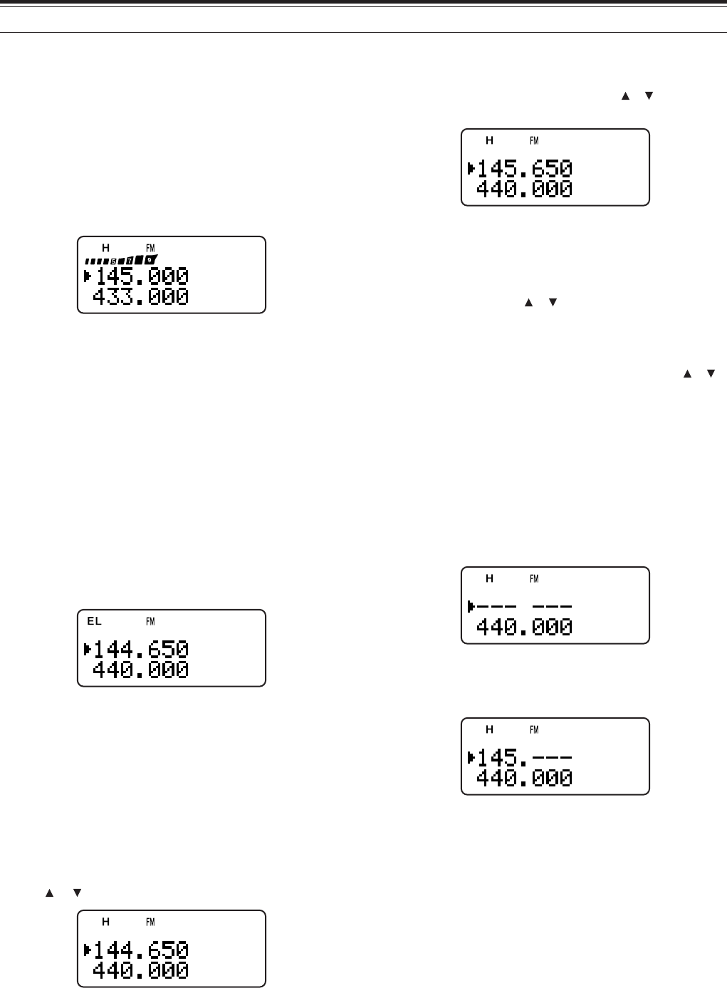
MHz SCAN
MHz Scan allows you to scan an entire 1 MHz
frequency range within the current VFO frequency.
1Press [VFO].
2Turn the Tuning control or press [ ]/ [ ] to select
a frequency in which to perform the MHz Scan. If
you want to scan the entire 145 MHz frequency,
select any frequency between 145.000 and
149.995 MHz (for example, select 145.650 MHz).
Scan will operate between 145.000 MHz and
145.999 MHz.
3Press [MHz] (1 s) to start the MHz Scan.
4To stop the MHz Scan, press [MHz] or [PTT].
Note:
◆
If the Fine Tuning function is ON, you cannot perform the MHz
Scan.
◆
The transceiver stops scanning in only the AM and FM modes
when it detects a signal.
◆
If you press [MONI], MHz Scan temporarily pauses. Release
[MONI] to resume scanning.
◆
If you press any of the following keys during the scan, the
transceiver exits the Scan: [F] (1 s), [LAMP], [MONI], [SQL],
Tuning control, [ ], and [ ]
◆
When the CTCSS or DCS function is activated, the transceiver
stops at a busy frequency and decodes the CTCSS tone or DCS
code. If the tone or code matches, the transceiver unmutes.
Otherwise, it resumes scanning.
PROGRAM SCAN
You can limit the scanning frequency range. There
are 10 memory channel pairs (L0/ U0 ~ L9/ U9)
available for specifying the start and end frequencies.
It monitors the range between the start and end
frequencies that you have stored in memory channels
L0/ U0 to L9/ U9. Before performing the Program
Scan, store the Program Scan frequency range to
one of the memory channels L0/ U0 ~ L9/ U9.
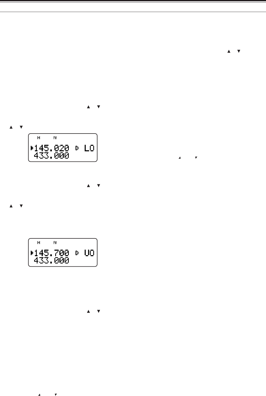
■Storing Program Scan Frequency Range
1Press [VFO].
2Press [BAND] to select your desired band.
3Turn the Tuning control or press [ ]/ [ ] to select
your desired start frequency.
4Press [F], then turn the Tuning control or press
[ ]/ [ ] to select a memory channel from L0 ~ L9.
5Press [MR] to store the start frequency in the
memory channel.
6Turn the Tuning control or press [ ]/ [ ] to select
your desired end frequency.
7Press [F], then Turn the Tuning control or press
[ ]/ [ ] to select the corresponding channel from
U0 ~ U9 (you must select the same numeric value
as in step 4).
• For example, if you selected L0 in step 4, you
must select U0 in this step.
8Press [MR] to store the end frequency in the
memory channel.
■Performing the Program Scan
1Press [VFO].
2Turn the Tuning control or press [ ]/ [ ] to select
a frequency within the frequency range of memory
channel L0/ U0 ~ L9/ U9.
3Press [VFO] (1 s) to start the Program Scan.
4To stop the Program Scan, press [VFO] or [PTT].
Note:
◆
If you press [MONI], Program Scan temporarily pauses. Release
[MONI] to resume scanning.
◆
The transceiver stops scanning only in the AM and FM modes
when it detects a signal.
◆
If the Fine Tuning function is ON, the scanning does not stop at
the busy channels.
◆
If you press any of the following keys during the scan, the
transceiver exits the Scan: [F] (1 s), [LAMP], [MONI], [SQL],
Tuning control, [ ], and [ ]
24
14 SCAN
MEMORY SCAN
Memory Scan monitors all memory channels in which
you have stored frequencies (All-Channel Scan) or
only a desired group of memory channels (Group
Scan).
ALL-CHANNEL SCAN
The transceiver scans all of the memory channels in
which you have stored frequencies.
1Press [MR] (1 s).
• Scan starts from the last memory channel
number and ascends up through the channel
numbers (default). Turn the Tuning control or
press [ ]/ [ ] to change the scanning direction.
• To jump to a desired channel while scanning,
quickly turn the Tuning control.
2To stop the All-Channel Scan, press [MR] or
[PTT].
Note:
◆
If the Fine Tuning function is ON, you cannot perform the All-
Channel Scan.
◆
If you press [MONI], All-Channel Scan temporarily pauses.
Release [MONI] to resume scanning.
◆
The transceiver stops scanning in all modes when it detects the
signal.
◆
If you press any of the following keys during the scan, the
transceiver exits the Scan: [F] (1 s), [LAMP], [MONI], [SQL],
Tuning control, [ ], and [ ]
GROUP SCAN
In order to easily manage all 400 memory channels,
they are divided into 8 groups {page 18}. For the
purpose of Group Scan, you can select a particular
memory group to be scanned, depending on the
situation. Using the Memory Group Link function
{below}, you can scan all the linked memory groups.
1Press [MR] to enter Memory Scroll mode.
2Turn the Tuning control or press [ ]/ [ ] to select
a memory channel in the group you want to scan.
For example, if you want to scan the group 0
memory channels, recall memory channel 12
(group 0 contains memory channels 0 ~ 49).
3Press [MHz] (1 s).
• The memory channels within the selected
group are scanned.
• If the group is linked to other groups {below},
all the linked groups are also scanned.
4To stop the Group Scan, press [MHz] or [PTT].
Note:
◆
If the Fine Tuning function is ON, you cannot perform the Group
Scan.
◆
If you press [MONI], All-Channel Scan temporarily pauses.
Release [MONI] to resume scanning.
◆
The transceiver stops scanning in all modes when it detects a
signal.
◆
If you press any of the following keys during the scan, the
transceiver exits the Scan: [F] (1 s), [LAMP], [MONI], [SQL],
Tuning control, [ ], and [ ]
■Memory Group Link
Although the 400 memory channels are divided into 8
groups {page 18}, you may sometimes want to scan
two or more groups. In this case, use the Memory
Group Link function.
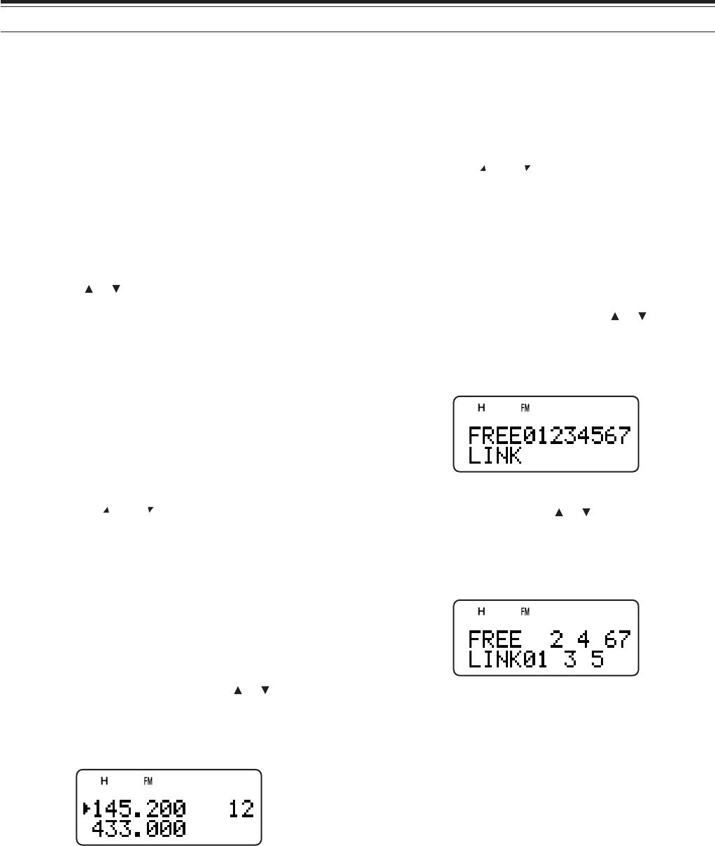
1Press [MNU] to enter Menu mode.
2Turn the Tuning control or press [ ]/ [ ] to select
Menu No. 2 (M.GRP LINK).
3Press [ss
ss
s] or [MNU].
• The memory group numbers appear.
4Move the cursor using [tt
tt
t]/ [ss
ss
s], then turn the
Tuning control or press [ ]/ [ ] to select or
deselect the group to be linked.
• Linked groups appear at the bottom of the
display (in the example below, groups 0, 1, 3
and 5 are linked).
5Press [MNU] to store the setting. Otherwise,
press [PTT] to cancel.
25
14 SCAN
CALL SCAN
A Call channel can be stored for each amateur radio
band, such as the 144 MHz, 430/ 440 MHz, and 220
MHz (TH-F6A only) bands {page 19}. You can
monitor one of these Call channels and the current
operating frequency alternatively.
1Select the frequency (in VFO or Memory Recall
mode) you want to monitor.
• In VFO mode, press [A/B] to select the A or
B-band. Then, turn the Tuning control or press
[ ]/ [ ] to select the desired frequency.
• In Memory Recall mode, turn the Tuning
control or press [ ]/ [ ] to select a memory
channel you want to monitor.
2Press [CALL] (1 s) to start the Call Scan.
3The Call channel for the band and the selected
VFO frequency or memory channel are monitored
alternatively.
4To stop the Call Scan, press [PTT] or [CALL].
Note:
◆
If you press [MONI], Call Scan temporarily pauses. Release
[MONI] to resume scanning.
◆
The transceiver stops scanning in all modes when it detects a
signal.
◆
If you press any of the following keys during the scan, the
transceiver exits the Scan: [F] (1 s), [LAMP], [MONI], [SQL],
and the Tuning control
PRIORITY SCAN
You may sometimes want to check your favorite
frequency activities while monitoring the A and
B-bands. In this case, use the Priority Scan function.
It checks the activities of Pr1 and Pr2 channels every
6 seconds, alternatively, using the B-band receiver. If
the transceiver detects a signal on Pr1 or Pr2, it
recalls the frequency to the B-band receiver.
Note: If you do not operate any control or key for 3 seconds after the
signal drops, the transceiver resumes Priority Scan.
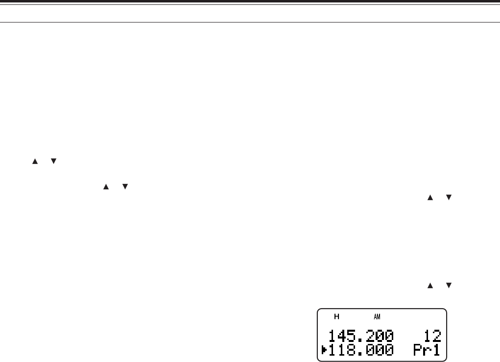
■Programming Priority channels
1Press [VFO].
2Turn the Tuning control or press [ ]/ [ ] to select
your desired priority channel frequency.
3Select the mode and selective call functions if
necessary.
4Press [F].
• The memory channel number appears.
5Turn the Tuning control or press [ ]/ [ ] to select
“Pr1”.
6Press [MR] to store the data on the priority
channel.
• If you want to store a second priority channel,
repeat steps 1 ~ 6 and select “Pr2” in step 5.
Note: You can program any frequency available on the B-band as a
priority channel.

26
14 SCAN
■Using Priority Scan
1Press [F], [BAL].
• “P” appears.
• The transceiver checks for a signal on the Pr1
and Pr2 channels every 6 seconds,
alternatively.
• When the transceiver detects a signal on the
priority channel, the B-band frequency changes
to the priority channel.
• If you do not operate any control or key for 3
seconds after the signal drops, the transceiver
resumes Priority Scan.
2To quit Priority Scan, press [F], [BAL] again.
Note:
◆
The signal being received on the B-band may become intemittent
beuase the Priority Scan uses the B-band receiver to check the
priority channel(s) activities.
◆
If you press any of the keys below during the scan, the
transceiver exits the scan: [A/B], [LAMP], [MONI], [SQL],
[F] (1s), [BAL], and [F] then [BAL]
◆
When a signal is received on a Priority channel with a CTCSS or
DCS code programmed, the Priority channel is recalled even if a
different selective tone/ code is detected. However, the
transceiver only unmutes if the signal has the same CTCSS tone
or DCS code.
◆
Press and hold [MONI] to pause the Priority Scan when the
transceiver is not displaying a priority channel. Release [MONI]
to resume the Priority Scan.
INFORMATION CHANNEL SCAN
Information channel scan is similar to group scan.
However, it scans only Information channels.
1Press [INFO].
• The last Information channel you used is
recalled.
2Press [INFO] (1 s) to start the Information
Channel Scan.
3To stop the Information Channel Scan, press
[INFO] or [PTT].
Note:
◆
If you press [MONI], Information Channel Scan temporarily
pauses. Release [MONI] to resume scanning.
◆
The transceiver stops scanning in all modes when it detects a
signal.
◆
If you press any of the following keys during the scan, the
transceiver exits the Scan: [F] (1 s), [LAMP], [MONI], [SQL],
Tuning control, [ ], and [ ]
VISUAL SCAN
While you are receiving, Visual Scan allows you to
monitor frequencies near the current operating
frequency. Visual Scan graphically displays the busy
status of all frequencies in the selected range. You
will see a maximum of 7 segments, for each
frequency (channel) point that represent relative S-
meter levels.
The Visual Scan monitors ±5 channels (frequencies)
by centering on the current channel (frequency). In
this way, a total of 11 channels’ (frequencies’) signal
strength status are graphically displayed.
Note: When you perform the Visual scan on the A-band, the
transceiver can output the audio. However, when you perform the
Visual Scan on the B-band, it cannot output the audio.
■Using Visual Scan (VFO)
1Select your desired band for Visual Scan.
2Turn the Tuning control or press [ ]/ [ ] to
select your desired center frequency.
• The transceiver scans the 5 upper
frequencies and 5 lower frequencies using
the current VFO frequency step.
3Press [F], [INFO] to start Visual Scan (VFO).
• The scanning frequency is displayed on the
current operating band and the relative
S-meter level of each frequency appears on
the other band display.
• To pause Scan, press and hold [MONI].
While the Visual Scan is paused, you can
monitor the paused frequency. Release
[MONI] to resume the Visual Scan.
4To change the current scanning frequency,
Turn the Tuning control or press [ ]/ [ ].
• The displayed frequency changes and the
cursor moves.
5To stop the Visual Scan, press [F], [INFO].
Note:
◆
If you press [MONI], Visual Scan temporarily pauses. Release
[MONI] to resume scanning. When it is paused, the center
frequency bar-graph blinks.
◆
Although you can perform the Visual Scan on the A or B-band,
the B-band cannot output the audio during the scan.
◆
You can press [PTT] or [CALL] (if 1750 Hz is programmed) to
transmit during the scan.
◆
If the Fine Tuning function is ON, the Visual Scan cancels the
FINE function and automatically adjusts the frequency to the next
available frequency.
27
14 SCAN
■Using Visual Scan (Memory Channel)
1Press [MR] to enter Memory Recall mode.
2Turn the Tuning control or press [ ]/ [ ] to
select your desired center memory channel.
3Press [F], [INFO] to start the Visual Scan.
4The transceiver start scanning the 5 upper
memory channels and 5 lower memory
channels, by centering the selected memory
channel.
• The current scanning memory channel
number and frequency are displayed on the
current operating band. On the other band,
the relative S-meter level of each frequency
channel is displayed.
• To pause Scan, press [MONI]. While the
Visual Scan is paused, you can monitor the
paused frequency. Press [MONI] again to
resume the Visual Scan.
6To change the current scanning channel, turn
the Tuning control or press [ ]/ [ ].
7To stop the Visual Scan, press [F], [INFO].
Note:
◆
If you press [MONI], Visual Scan temporarily pauses. Release
[MONI] to resume scanning. When it is paused, the center
frequency bar-graph blinks.
◆
Although you can perform the Visual Scan on the A or B-band,
the B-band cannot output the audio during the scan.
◆
You can press [PTT] or [CALL] (if 1750 Hz is programmed) to
transmit during the scan.
◆
If the Fine Tuning function is ON, the Visual Scan cancels the
FINE function and automatically adjusts the frequency to the next
available frequency.
SCAN RESUME METHOD
The transceiver stops scanning at the frequency (or
memory channel) where a signal is detected. It then
continues or stops scanning according to which
resume mode you have selected. You can choose
one of the following modes. The default is Time-
operated mode.
• Time-Operated mode (default)
The transceiver remains on a busy frequency (or
memory channel) for approximately 5 seconds,
then continues to scan, even if the signal is still
present.
• Carrier-Operated mode
The transceiver remains on the busy frequency (or
memory channel) until the signal drops out. There
is a 2 second delay between signal dropout and
scan resumption.
• Seek mode
The transceiver moves to a frequency or memory
channel where a signal is present and stops.
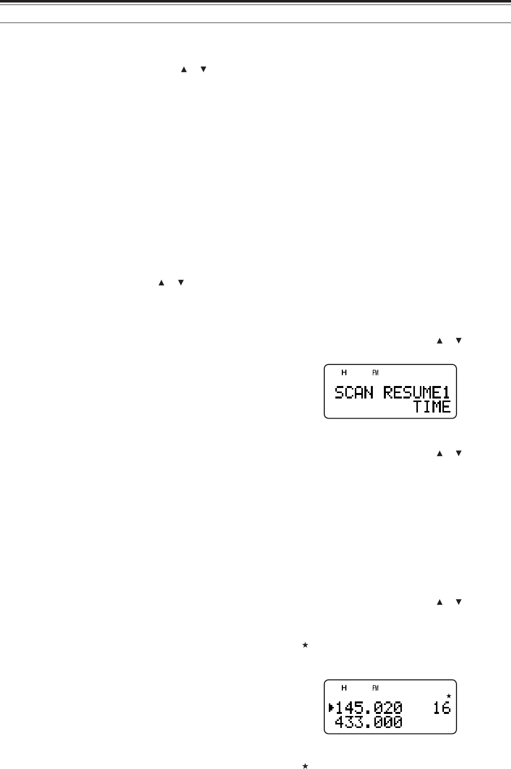
To change the scan resume method:
1Press [MNU].
2Turn the Tuning control or press [ ]/ [ ] to select
Menu No. 1 (SCAN RESUME).
3Press [ss
ss
s] or [MNU].
4Turn the Tuning control or press [ ]/ [ ] to select
“TIME ” (Time-Operated mode), “CARRIER”
(Carrier-Operated mode), or “SEEK” (Seek mode).
5Press [ss
ss
s] or [MNU] to store the setting.
Otherwise, press [tt
tt
t] or [PTT] to cancel.
MEMORY CHANNEL LOCKOUT
You can lock out memory channels that you prefer
not to monitor during Memory Scan.
1Press [MR] to enter Memory Recall mode.
2Turn the Tuning control or press [ ]/ [ ] to select
the memory channel to be locked out.
3Press [F], [MHz].
•“” appears at the top right of the memory
channel number, indicating the channel is
locked out.
4To unlock the memory channel, repeat steps 1 ~ 3.
•“” disappears.
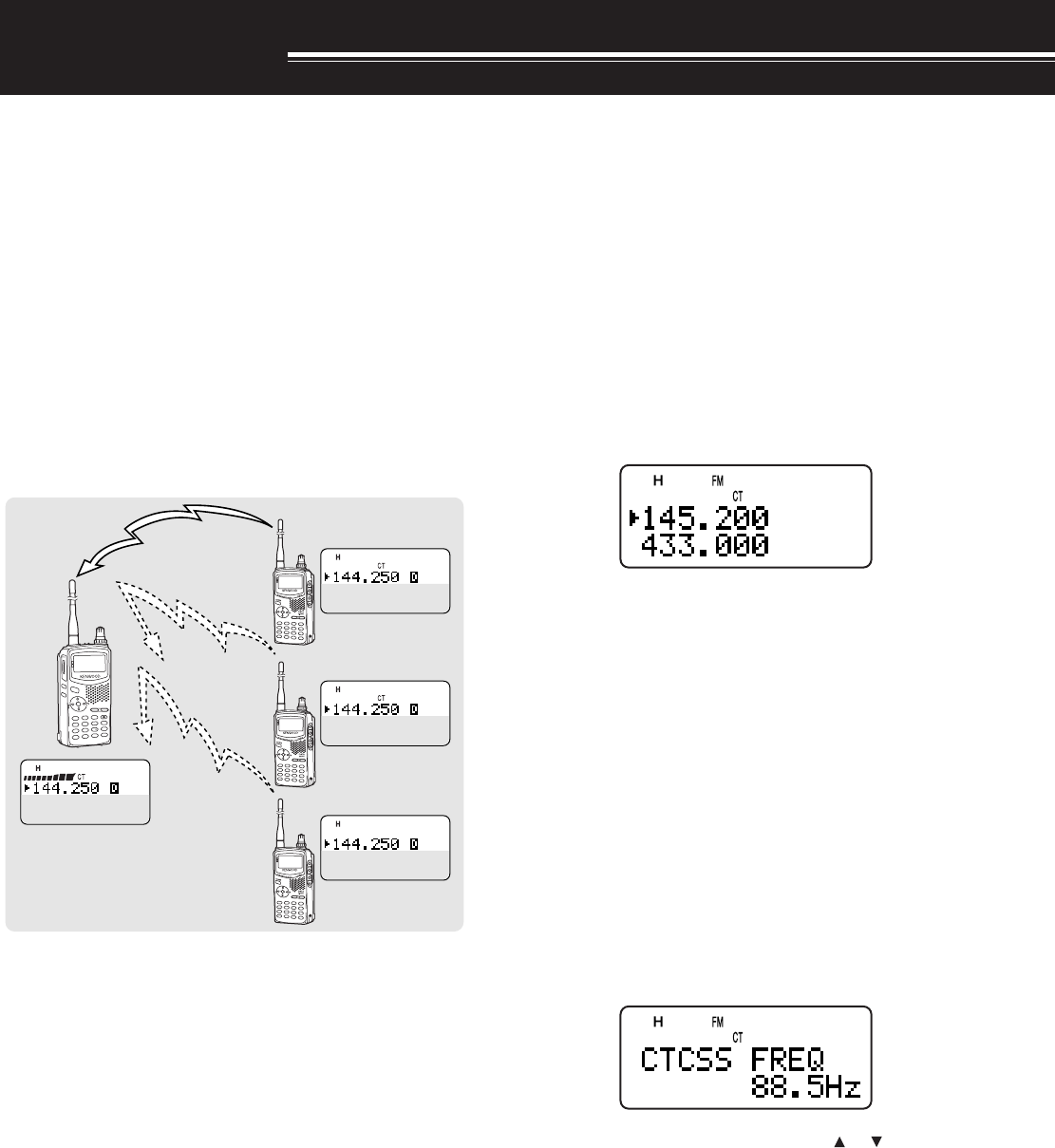
28
SELECTIVE CALL
CTCSS and DCS
You may sometimes want to hear calls from only
specific persons or groups. In this case, use the
selective call function. This transceiver is equipped
with CTCSS (Continuous Tone Coded Squelch
System) and DCS (Digital Coded Squelch). These
selective calls allow you to ignore (not hear)
unwanted calls from other persons who are using the
same frequency. The transceiver unmutes only when
it receives the signal having the same CTCSS tone or
DCS code.
Note:
◆
CTCSS and DCS do not cause your conversation to be private or
scrambled. It only relieves you from listening to unwanted
conversations.
◆
CTCSS and DCS function in only FM mode.
CTCSS (Continuous Tone Coded Squelch
System)
A CTCSS tone is a sub-audible tone and is selectable
from among the 42 tone frequencies listed in the
table on the following page. The list includes 37 EIA
standard tones and 5 non-standard tones. You can
select one of the tones to use as a CTCSS tone.
USING CTCSS
1Press [TONE] until “CT” appears.
• Each time you press [TONE], the icon cycles
as follows: “T” (TONE) ➞ “CT” (CTCSS) ➞
“DCS” (DCS) ➞ “ ” (OFF) ➞ “T” (TONE).
When the CTCSS funtion is ON, you will hear calls
only when the selected CTCSS tone is received. To
answer the call, press and hold the PTT switch, then
speak into the microphone.
Note:
◆
You cannot use the CTCSS and Tone/ DCS functions
simultaneously. Switching the CTCSS function ON after having
activated the Tone/ DCS functions deactivates the Tone/ DCS
functions.
◆
If you select a high CTCSS frequency, receiving audio or noise
that contains the same frequency portions may cause CTCSS to
function incorrectly. To prevent noise from causing this problem,
select an appropriate squelch level {page x}.
SELECTING A CTCSS FREQUENCY
1While in CTCSS mode {above}, press [F],
[TONE].
• The current CTCSS frequency appears.
2Turn the Tuning control or press [ ]/ [ ] to select
your desired CTCSS frequency.
• The selectable CTCSS frequencies are the
same as those for the Tone frequency. Refer to
the table on the following page for the available
CTCSS frequencies.
3Press [ss
ss
s] or [MNU] to store the new setting.
Otherwise, press [tt
tt
t] or [PTT] to cancel.
A/B
BAL
TNC
MENU
LISTBCONVFO
REVDUP
MHzDUALENTCALL
MN fMR
POS
MSG
POWER
ESC
OK
DATA
AX.25PROTOCOL
STSTACONCON
PACKET
9696
BCON
DUP
9
7
5
STSTACONCON
PACKET
9696
BCON
DUP
9
7
5
STSTACONCON
PACKET
9696
BCON
DUP
9
7
5
STSTACONCON
PACKET
9696
BCON
DUP
9
7
5
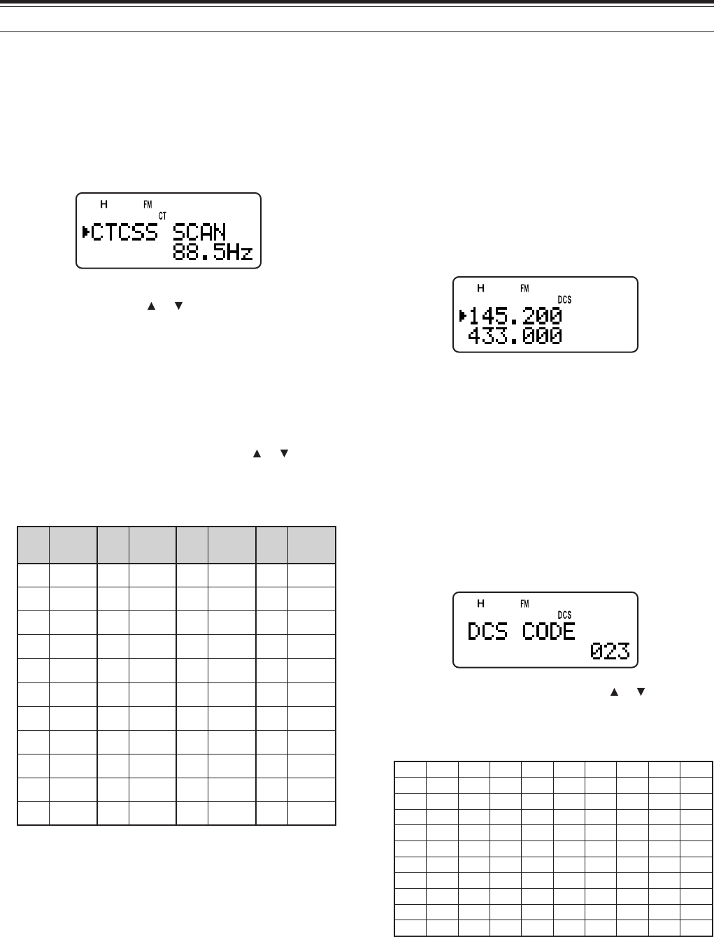
29
7 SELECTIVE CALL
CTCSS FREQ. ID SCAN
This function scans through all CTCSS frequencies to
identify the incoming CTCSS frequency on the
received signal. You may find this useful when you
cannot recall the CTCSS frequency that the other
persons in your group are using.
1While the CTCSS function is ON, press [TONE]
(1 s) to start the CTCSS Freq. ID Scan function.
• To reverse the scan direction, turn the Tuning
control or press [ ]/ [ ].
• To quit the function, press [tt
tt
t].
•When a CTCSS frequency is identified, the
identified frequency appears and blinks.
2Press [ss
ss
s] or [MNU] to program the identified
frequency in place of the current CTCSS
frequency. Otherwise, press [tt
tt
t] if you do not
want to program the identified frequency.
• Turn the Tuning control or press [ ]/ [ ] while
the identified frequency is blinking to resume
scanning.
Available CTCSS frequencies
.oN .qerF )zH( .oN .qerF )zH( .oN .qerF )zH( .oN .qerF )zH(
100.76214.79323.141435.602
203.96310.001422.641537.012
309.17415.301524.151631.812
404.47512.701627.651737.522
500.77619.011722.261831.922
607.97718.411829.761936.332
705.28818.811928.371048.142
804.58910.321039.971143.052
905.88023.721132.681241.452
015.19128.131238.291
118.49225.631335.302
Note:
◆
Received signals are monitored through the speaker while
scanning is in progress.
◆
If the CTCSS function is activated for both the A and B-band, the
scan speed may be slower.
DCS (Digital Coded Squelch)
DCS is similar to CTCSS. However, instead of using
an analog signal, it uses a continuous sub-audible
digital wave form that represents a 3-digit octal
number. You can select a DCS code from among the
104 DCS codes listed in the table below.
USING DCS
1Press [TONE] until “DCS” appears.
• Each time you press [TONE], the icon cycles
as follows: “T” (TONE) ➞ “CT” (CTCSS) ➞
“DCS” (DCS) ➞ “ ” (OFF) ➞ “T” (TONE).
When the DCS function is ON, you will hear calls only
when the selected DCS code is received. To answer
the call, press and hold the PTT switch, then speak
into the microphone.
Note: You cannot use the DCS funtion and CTCSS/ Tone functions
simultaneously. Switching the DCS function ON after having
activated the CTCSS/ Tone functions deactivate the CTCSS/ Tone
functions.
SELECTING A DCS CODE
1While in DCS mode {above}, press [F], [TONE].
• The current DCS code appears.
2Turn the Tuning control or press [ ]/ [ ] to select
your desired DCS code.
• The available DCS codes are shown in the
following table.
320560231502552133314564216137
520170431212162233324664426237
620270341322362343134305726437
130370541522562643234605136347
230470251622662153544615236457
630411551342172653644325456
340511651442472463254625266
740611261542603563454235466
150221561642113173554645307
350521271152513114264565217
450131471252523214464606327
3Press [ss
ss
s] or [MNU] to store the new setting.
Otherwise, press [tt
tt
t] or [PTT] to cancel.

7 SELECTIVE CALL
30
DCS CODE ID SCAN
This function scans through all DCS codes to identify
the incoming DCS code on the received signal. You
may find this useful when you cannot recall the DCS
code that the other persons in your group are using.
1While in DCS mode, press [TONE] (1 s) to start
the DCS Code ID Scan function.
• To reverse the scan direction, turn the Tuning
control or press [ ]/ [ ].
• To quit the function, press [tt
tt
t].
•When a DCS code is identified, the identified
code appears and blinks.
2Press [ss
ss
s] or [MNU] to program the identified
frequency in place of the current DCS code.
Otherwise, press [tt
tt
t] if you do not want to
program the identified code.
• Turn the Tuning control or press [ ]/ [ ] while
the identified DCS code is blinking to resume
scanning.
Note:
◆
Received signals are monitored through the speaker while
scanning is in progress.
◆
If the DCS function is activated for both the A and B-band,
the scan speed may be slower.
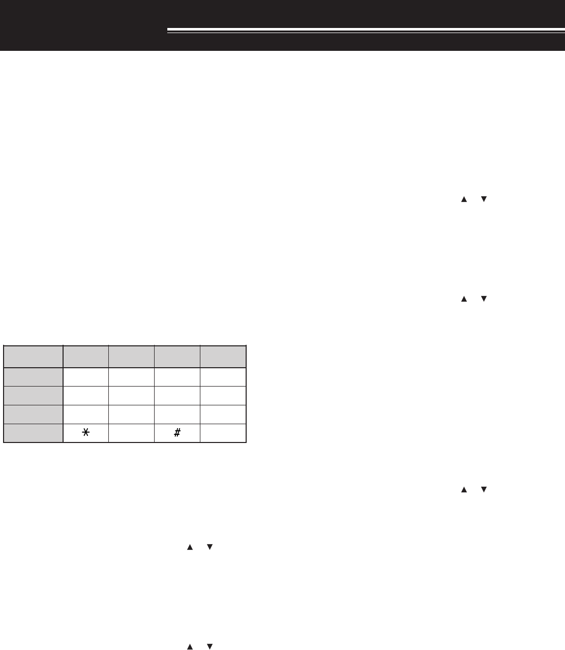
31
DTMF FUNCTIONS
The keys on the keypad also function as DTMF keys;
the 12 keys found on a push-button telephone plus 4
additional keys (A, B, C, D). This transceiver also
provides 10 dedicated DTMF memory channels. You
can store a DTMF number (16 digits max.) with a
memory name (8 digits max.) in each of the channels
to recall later for a speed dialingl.
Many repeaters in the U.S.A. and Canada offer a
service called Autopatch. You can access the public
telephone network via such a repeater by sending
DTMF tones. For further information, consult your
local repeater reference.
MANUAL DIALING
Manual Dialing requires only two steps to send DTMF
tones.
1Press and hold the PTT switch to transmit.
2While transmitting, press the keys in sequence on
the keypad to send DTMF tones.
• The corresponding DTMF tones are
transmitted and monitored through the speaker.
■TX Hold
This function makes the transceiver remain in
transmit mode for 2 seconds after you release
each key. So you can release the PTT switch
while sending the DTMF tones.
1Press [MNU] to enter Menu mode.
2Turn the Tuning control or press [ ]/ [ ] to
select the Menu No. 12 (DTMF HOLD).
3Turn the Tuning control or press [ ]/ [ ] to
select “ON”.
4Press [ss
ss
s] or [MNU] to store the setting.
Otherwise, press [tt
tt
t] or [PTT] to cancel.
AUTOMATIC DIALER
If you use the 10 dedicated memory channels to store
DTMF numbers, you need not remember a long string
of digits.
■Storing a DTMF Number in Memory
Note: Audible DTMF tones from other transceivers near you (or
from your own speaker) may be picked up by your microphone.
If so, you may fail to correctly program a DTMF number.
1Press [MNU] to enter Menu mode.
2Turn the Tuning control or press [ ]/ [ ] to
select the Menu No. 10 (DTMF STORE).
3Turn the Tuning control or press [ ]/ [ ] to
select a desired DTMF memory channel
number from 0 to 9.
4Press [ss
ss
s] or [MNU].
• The display for entering a memory name
appears; the first digit blinks.
• To skip naming the channel, press [ss
ss
s] or
[MNU] again. You can jump to step 8.
5Turn the Tuning control or press [ ]/ [ ] to
select a character.
• You can enter alphanumeric characters plus
special ASCII characters.
•[MONI] to delete a charactor on the cursor.
• You can also use the numeric keypad to
enter a character (Special ASCII charactors
are not available).
• Press [LAMP]+turning Tuning control to
jump to the first charactor of each character
type in the ASCII table.
6Press [ss
ss
s] to move the cursor to the next digit.
7Repeat steps 5 and 6 to enter up to 8 digits.
• Pressing [ss
ss
s] after selecting the 8th digit
causes the cursor to move to the start of the
next field.
• To complete programming the name less
than 8 digits, press [ss
ss
s] twice.
)zH(.qerF 9021 6331 7741 3361
796 123A
077 456B
258 789C
149 0D

32
8 DTMF FUNCTIONS
• Each press of [tt
tt
t] causes the cursor to
move backward.
8Press the keys in sequence on the keypad to
enter a DTMF number with up to 16 digits.
• You can also turn the Tuning control or
press [ ]/ [ ] to select the required DTMF
number for each digit. Select a space if you
want to put a pause.
9Press [ss
ss
s] or [MNU] to complete the
programming.
You can confirm the stored DTMF number by
using steps 1 to 3.
You can also use the keypad to enter
alphanumeric characters in step 5. For example,
each press of [BAND] switches entry as A, B, C,
a, b, c, then 2.
■Transmitting a Stored DTMF Number
1Press [PTT]+[MNU].
2Release only [MNU], then turn the Tuning
control or press [ ]/ [ ] to select the desired
DTMF memory channel.
3While still holding [PTT], press [ss
ss
s] or [MNU]
to trasmit the DTMF tones.
• The number stored in the channel scrolls
across the display accompanied by DTMF
tones from the speaker.
• After transmission, the frequency display is
restored.
If you need not confirm the memory channel
contents, press [0] to [9] instead of turning the
Tuning control or pressing [ ]/ [ ] in step 2 to
select a channel number. The stored DTMF
number will be immediately transmitted. You need
not press [ss
ss
s] or [MNU] in step 3.
■Adjusting the DTMF tone tranmission speed
This transceiver allows you to configure the DTMF
number transmission speed between Fast
(default) and Slow. If a repeater cannot respond
to the fast speed, adjust this parameter.
1Press [MNU] to enter Menu mode.
2Turn the Tuning control or press [ ]/ [ ] to
select the Menu No. 11 (DTMF SPD).
3Press [ss
ss
s] or [MNU]
4Turn the Tuning control or press [ ]/ [ ] to
select “FAST” (default) or “SLOW”.
• The tone duration of FAST is 50 ms and
SLOW is 100 ms.
5Press [ss
ss
s] or [MNU] to store the new setting.
■Adjusting the pause duration
You can also change pause duration (a space
digit) stored in memory channels; the default is
500 msec.
1Press [MNU] to enter Menu mode.
2Turn the Tuning control or press [ ]/ [ ] to
select the Menu No. 13 (DTMF PAUSE).
3Press [ss
ss
s] or [MNU]
4Turn the Tuning control or press [ ]/ [ ] to
select 100/ 250/ 500 (default)/ 750/ 1000/ 1500/
2000 msec.
5Press [ss
ss
s] or [MNU] to store the new setting.
DTMF LOCK
Assuming you have a transceiver with the optional
speaker microphone installed and you are carrying it
in the holder or bag, you sometimes want to disable
the keypad DTMF transmission to avoid the
accidental DTMF transmission. In this case, turn the
DTMF Lock function ON.
1Press [MNU] to enter Menu mode.
2Turn the Tuning control or press [ ]/ [ ] to select
the Menu No. 14 (DTMF LOCK).
3Press [ss
ss
s] or [MNU]
4Turn the Tuning control or press [ ]/ [ ] to select
“ON”.
5Press [ss
ss
s] or [MNU] to store the setting.
When this function is activated, you cannot transmit
DTMF tones using the DTMF keypad (including
[MNU]) during the transmission.
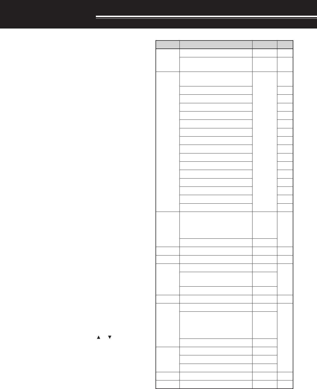
35
UTILIZING B-BAND
ABOUT B-BAND
Usually you can communicate with other amateur
radio stations using A-band frequencies for receiving
and transmitting. This transceiver also features
another receiver in addition to A-band transceiver.
The frequency for the B-band appears the bottom
part of the display. Although A-band transceiver
covers only 144 MHz/ 220 MHz (TH-F6A only)/ 430/
440 MHz amateur radio bands in FM mode, B-band
receiver can receive from 100 kHz to 470 MHz in
SSB, CW, FM, or AM mode. From 470 MHz to
1.3 GHz, you can also receive in FM or AM mode.
In this way, you can monitor 2 different frequencies at
the same time. This means that you can listen to a
local FM broadcasting station while you are
monitoring your club channel at the same time.
If one of A-band amateur radio bands is also selected
for B-band in FM mode, you can also transmit on the
B-band frequency.
B-BAND FREQUENCY
Since B-band frequency coverage is so wide, the
default frequency band, mode, and frequency step
size are preprogrammed as shown below.
1Press [A/B] to select B-band.
•“s” icon moves, indicating which band is
currently selected.
2Press [BAND] until the desired frequency band
appears.
• Each time you press [BAND], the frequency
band cycles from the last band you selected to
upper band frequency. When it reaches to 1.2
GHz band, it goes back to LW band.
3Turn the Tuning control or press [ ]/ [ ] to tune to
a desired frequency.
Note: You can also select one of the amateur radio band to transmit
on the B-band frequency. However, the operating mode must be in
FM mode to transmit.
■B-band Frequency Coverage
dnaB ycneuqerF petS edoM
dnabMA
zHk025~zHk001zHk1MA
)A6F-HT(zHM8.1~zHk025 )E7F-HT(zHM17.1~zHk025 zHk01MA
FH
)A6F-HT(zHM5.3~zHM8.1 )E7F-HT(zHM5.3~17.1
zH001 )NOENIF(
MA
zHM0.4~zHM5.3BSL
zHM0.7~zHM0.4MA
zHM3.7~zHM0.7BSL
zHM1.01~zHM3.7MA
zHM51.01~zHM1.01WC
zHM0.41~zHM51.01MA
zHM53.41~zHM0.41BSU
zHM860.81~zHM53.41MA
zHM861.81~zHM860.81BSU
zHM0.12~zHM861.81MA
zHM54.12~zHM0.12BSU
zHM98.42~zHM54.12MA
zHM99.42~zHM98.42BSU
zHM0.82~zHM99.42MA
zHM7.92~zHM0.82BSU
m6 zHM0.05~zHM7.92
zHk52 )A6F-HT( zHk5 )E7F-HT( MF
zHM0.45~zHM0.05zHk01
dnabMFzHM0.801~zHM0.45zHk001WMF
dnabriAzHM0.731~zHM0.801zHk52MA
m2
zHM0.441~zHM0.731zHk5
MFzHM0.641~zHM0.441 5/5.21 zHk
zHM0.471~zHM0.641zHk5
VTFHVzHM0.612~zHM0.471zHk001WMF
zHM0.222~zHM0.612zHk5.21
MF
m3.1zHM0.532~zHM0.222
zHk02 )A6F-HT( zHk5.21 )E7F-HT(
zHM0.004~zHM0.532zHk5.21
zHM0.034~zHM0.004zHk5.21
mc07zHM0.054~zHM0.034zHk52
zHM0.074~zHM0.054zHk5.21
VTFHUzHM0.608~zHM0.074zHk001WMF
mc32zHM0.0031~zHM0.608zHk52MF
Note:
◆
By a default, FINE mode is activated automatically for 1.8 MHz ~
29.7 MHz.
◆
LSB/ USB/ CW mode operation is limited below 600 MHz.
◆
Cellular band is blocked due to government regulations.
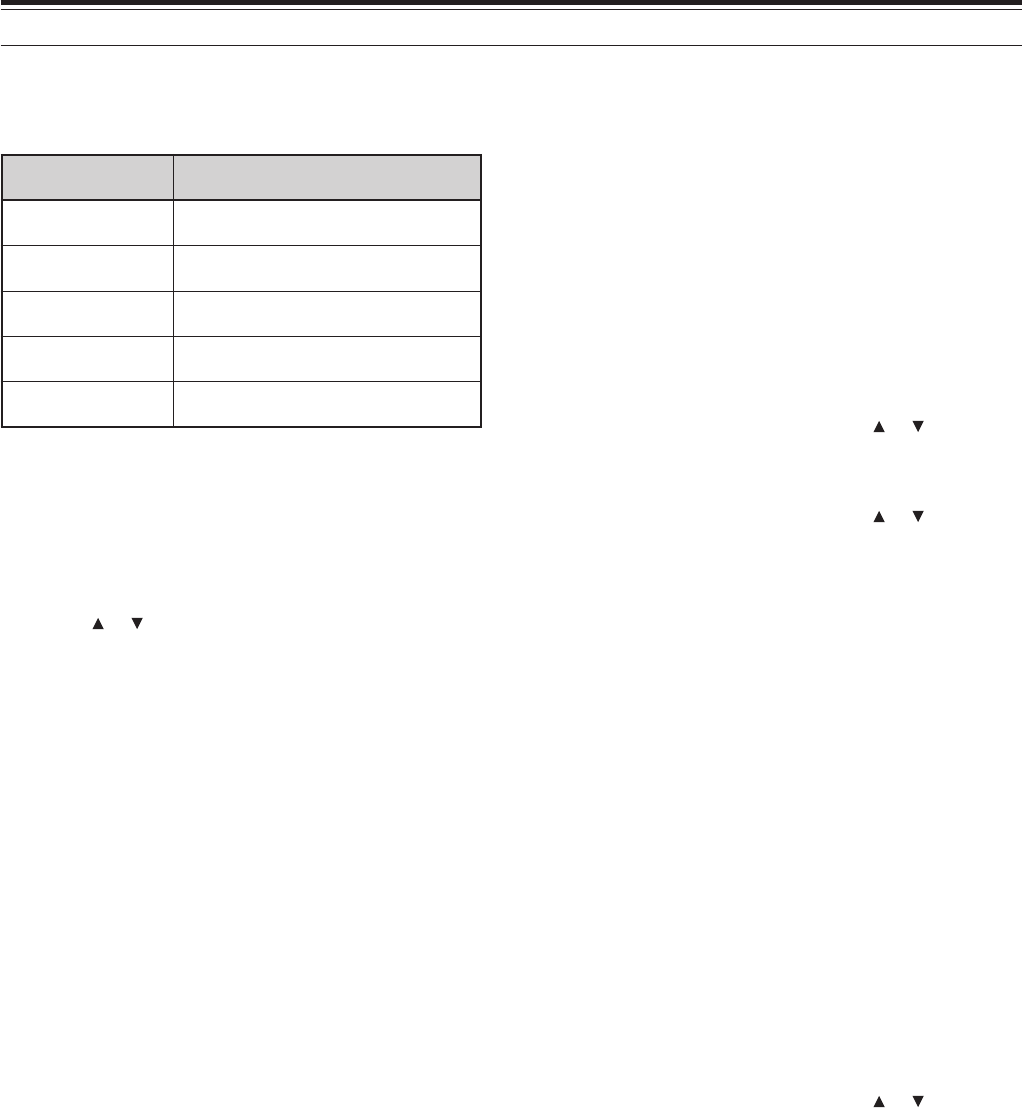
36
8 ENHANCED COMMUNICATIONS
SELECTING A MODE FOR B-BAND
When using B-band, the following receiving mode is
available.
edomgnivieceR segnarycneuqerfelbaliavA
BSU/BSLzHk001 ≤zHM074<f
WCzHk001 ≤zHM074<f
MAzHk001 ≤zHG3.1<f
NMF/MFzHM7.92 ≤zHG3.1<f
MFWzHM7.92 ≤zHG3.1<f
■LSB/ USB/ AM/ FM/ WFM
To select the receiving mode for B-band:
1Press [VFO].
2Press [A/B] to select B-band.
3Press [BAND] and then turn the Tuning control or
press [ ]/ [ ] to select the desired frequency.
4Press [MODE] until you select the desired
receiving mode. The mode icon cycles
FM ➞ WFM ➞ AM ➞ LSB ➞ USB ➞ CW, and
then goes back to FM.
Note:
◆
To select FMN (Narrow FM), access Menu No. 29 and select
“ON” {below}.
◆
LSB, USB, and CW modes can be selected in the frequencies
below 470 MHz only.
BAR ANTENNA
Although the supplied wide-band helical antenna is
used for receiving B-band frequencies, due to the
size and length limitation, it may not suitable for the
low HF band (below 7 MHz) receiption. The
transceiver features a built-in bar antenna for the
receiption frequency below 7 MHz. The transceiver
automatically switches to the bar antenna when you
select a frequency below 7 MHz for the B-band.
However, you can connect an external antenna to the
antenna connector instead.
To disable the built-in bar antenna:
1Press [MNU].
2Turn the Tuning control or press [ ]/ [ ] to select
Menu No. 26 (BAR ANT).
3Press [ss
ss
s], [MNU].
4Turn the Tuning control or press [ ]/ [ ] to select
“DISABLE”.
FINE TUNING MODE
When you operate the B-band in LSB, USB, CW, or
AM mode, you can turn the FINE Tuning function ON.
The Fine Tuning frequency step size can be selected
from 50 Hz, 100 Hz (default), or 1000 Hz.
■Activating Fine Tuning
To activate the FINE Tuning function:
1Select a frequency (below 470 MHz) on
the B-band.
• Operating mode must be LSB, USB, CW or
AM.
2Press [FINE].
• 100 Hz digits appears.
3Turn the Tuning control or press [ ]/ [ ] to tune to
a station.
Note:
◆
Fine Tuning functions works only when you operate the
frequency below 470 MHz.
◆
You cannot activate the Fine Tuning function on the A-band.
◆
When you change the mode to FM, the frequency will be
automatically adjusted to the next available frequency.
◆
While in the Fine Tuning mode, you cannot perform VFO step
size change {page xx}, MHz mode {page xx}, and MHz Scan
{page xx}.
◆
When you perform the Visual Scan {page xx}, Information
Channel Memory recall {page xx}, Information Channel Scan
{page xx}, VFO mode {page xx}, Memory channel recall {page
xx}, Call channel recall {page xx}, or direct frequency entry {page
xx}, the transceiver exits the Fine Tuning mode.

37
8 ENHANCED COMMUNICATIONS
■Selecting Fine Tuning Frequency step
You can select the Fine Tuning frequency step from
50 Hz, 100 Hz (default), or 1000 Hz.
To select the Fine Tuning frequency step size:
1Select a frequency on the B-band.
2Press [F], [FINE].
• Current frequency step size appears.
3Turn the Tuning control or press [ ]/ [ ] to select
a desired frequency step from 50 Hz, 100 Hz
(default), or 1000 Hz.
4Press [ss
ss
s] or [MNU] to store the new setting.
Note: The Fine Tuning frequency step size reflects all available
frequencies for the B-band.

38
OPERATOR CONVENIENCES
BATTERY SAVER
Battery Saver extends the operating time of the
transceiver. It becomes automatically active when
the squelch is closed and no key is pressed for more
than 10 seconds. To reduce the battery consumption,
it shuts the receiver circuit OFF for the programmed
time then momentarily ON to detect the signal. To
program the receiver shut-off period for the battery
saver:
1Press [MNU].
2Turn the Tuning control or press []/ [ ] to select
Menu No. 17 (BAT SAVER).
3Press [ss
ss
s] or [MNU].
4Turn the Tuning control or press []/ [ ] to select
the receiver shut-off period from OFF, 0.2, 0.4,
0.6, 0.8, 1.0 (default), 2.0, 3.0, 4.0, and
5.0 seconds.
5Press [ss
ss
s] or [MNU] to store the setting.
Note: Longer period, more you can save the battery consumption.
However, more chances of missing the signal.
BATTERY REMAINING
You can confirm the remaining Ni-ion battery capacity
using this function. To confirm the Ni-ion battery
remaining capacity:
Press [F], [LOW].
• Battery remaining indicator appears.
: more than 70 %
: 40 % ~ 70 %
: less than 40 %
: needs recharging
Note: When DC IN jack is connected to the DC source (13.8 V DC),
“CHARGING” (charging the Ni-ion battery) or “STANDBY” (charging
has completed) appears.
BEEP FUNCTION
The Beep function provides you confirmation of entry,
error status, and malfunctions of the transceiver. We
recommend you leave it ON in order to detect
erroneous operatins and malfunctions. However, to
turn the beep function OFF:
1Press [MNU].
2Turn the Tuning control or press []/ [ ] to select
Menu No. 19 (KEY BEEP).
3Press [ss
ss
s] or [MNU].
4Turn the Tuning control or press []/ [ ] to select
“OFF”.
5Press [ss
ss
s] or [MNU] to store the setting.
APO (Auto Power OFF)
The TH-F6A/ TH-F7E switches OFF automatically if
no keys or controls are pressed or adjusted for 30
minutes (default). 1 minute before the transceiver
switches OFF, warning beeps are output for a few
seconds and “APO” appears on the display. You can
select the APO time from OFF (disable), 30 (default),
and 60 minutes.
1Press [MNU].
2Turn the Tuning control or press []/ [ ] to select
Menu No. 18 (APO).
3Press [ss
ss
s] or [MNU].
4Turn the Tuning control or press []/ [ ] to select
the APO time from OFF, 30, or 60 minutes.
5Press [ss
ss
s] or [MNU] to store the setting.
Note:
◆
The APO function works even if the transceiver is scanning.
◆
The APO timer starts counting down the timer when no key
presses, no control adjustments, and no command (RS-232C
port) sequences are detected.
ATTENUATOR
The attenuator function is useful when extremely
strong signals exist nearby your receiving frequency.
When these type of signals exist nearby your
receiving frequency, the receiver gain control may be
erroneously controlled and overloaded by the strong
signals, rather than by the target receiving signal. If
this happens, the target receiving signal can be
masked and buried by the strong signals. In this
case, turn the Attenuator function ON. However, as a
side effect, the target signal is also attenuated. You
may have to adjust the VOL control to increase the
audio output level when it is ON.
1Press [F], [MONI].
• “ATT ON” appears momentarily on the B-band
display and the mode indicator blinks while it is
ON.
2To turn the attenuator function OFF, press [F],
[MONI] again.
• The mode indicator quits blinking when it is
OFF.
Note:
◆
When the attenuator function is ON, both A-band and B-band,
are attenuated. You cannot set the attenuator function
independently for each band.
◆
ATT function is disabled while scanning.

39
15 OPERATOR CONVENIENCES
The transceiver generates the following warning
beeps even if the beep function is turned OFF.
• DC voltage error {page 2}.
• PLL circuit malfunctions.
Note: A beep output level is linked the VOL control position.
BEAT SHIFT
Since the transceiver uses a microprocessor to
control various functions of the transceiver, the CPU
clock oscillator’s harmonics or image may appear on
some spots of the receiving frequencies. In this case,
turn the Beat Shift function ON.
1Press [MNU].
2Turn the Tuning control or press []/ [ ] to select
Menu No. 25 (BEAT SHIFT).
3Press [ss
ss
s] or [MNU].
4Turn the Tuning control or press []/ [ ] to select
“ON”.
5Press [ss
ss
s] or [MNU] to store the setting.
DISPLAY CONTRAST
You can adjust the LCD contrast level from 1
(weakest) to 16 (strongest) by accessing Menu No.
16 (CONTRAST). A default level is 8.
1Press [MNU].
2Turn the Tuning control or press []/ [ ] to select
Menu No. 16 (CONTRAST).
3Press [ss
ss
s] or [MNU].
4Turn the Tuning control or press []/ [ ] to adjust
the LCD contrast.
• The relative contrast level appears in a bar-graph.
5Press [ss
ss
s] or [MNU] to store the setting.
FREQUENCY STEP SIZE
Choosing the correct frequency step size is essential
in order to select your exact receive frequency using
the Tuning control or pressing []/ [ ]. You can
select your desired frequency step size from:
5 kHz, 6.25 kHz, 8.33 kHz (118 MHz band only),
9 kHz (AM broadcasting band only) , 10 kHz,
12.5 kHz, 15 kHz, 20 kHz, 25 KHz, 30 kHz, 50 kHz,
100 kHz.
The default step size for the amateur radio bands are
as follows.
dnaB oidarruetamA dnab A6F-HT E7F-HT
dnab-A
zHM441zHk5zHk5.21
zHM022zHk02—
zHM044/034zHk52zHk52
dnab-B
zHM441zHk5zHk5.21
zHM022zHk02zHk5.21
zHM044/034zHk52zHk52
zHG2.1zHk52zHk52
For B-band, refer to the page 35 for the default
frequency step size for other frequency bands. The
transceiver stores the frequency step size parameter
for each band independently. You can also further
fine tune the frequency in LSB, USB, AM, CW modes
on the B-band. Refer to FINE tuning function
{page 36}.
Note: If you change the frequency step size that does not match the
current operating frequency, the transceiver automatically adjust the
frequency that matches new frequency step size.
LAMP
You can illuminate the transceiver display by pressing
[LAMP]. Approximately 5 seconds after releasing
[LAMP], the light goes OFF if no other key is
pressed. Pressing any key other than [LAMP] while
the display is lit, restarts the 5-second timer; pressing
[LAMP] turns OFF the light immediately.
To keep the light ON continuously, press [F], [LAMP].
The light remains ON until you press [F], [LAMP].
LOCK FUNCTION
Lock function disables the most of keys to prevent
you from accidentally activating a function or
changing the current settings.
Press [F] (1 s) to toggle Lock function ON or OFF.
•“ ” appears when this function is ON.
However, the following keys are not locked:
[LAMP], [MONI], [SQL], [PTT], [F] (1 s), [ ], and
[F] then [LAMP].
Note: The Tuning control is also locked. To unlock the Tuning
control while the Lock function is ON, turn the Tune Enable function
ON.
■Tune Enable
Even if the Lock function is ON, you sometimes want
to turn the Tuning control to change the frequency.
In this case, turn this function ON.
1Press [MNU].
2Turn the Tuning control or press []/ [ ] to select
Menu No. 7 (TUNE ENABLE).
3Press [ss
ss
s] or [MNU].
4Turn the Tuning control or press []/ [ ] to select
“ON”.
5Press [ss
ss
s] or [MNU] to store the setting.
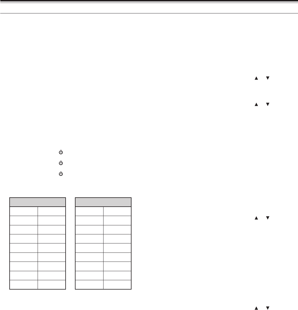
40
15 OPERATOR CONVENIENCES
NARROW BAND FM OPERATION
By a default, if you select FM mode, the transceiver
operates in normal FM deviation (± 25kHz) mode for
both transmission and receiption. However, you can
operates the transceiver in narrow band FM deviation
(± 12.5kHz) mode. To operate the narrow band FM:
1Press [MNU].
2Turn the Tuning control or press []/ [ ] to select
Menu No. 29 (FM NARROW).
3Press [ss
ss
s] or [MNU].
4Turn the Tuning control or press []/ [ ] to select
“ON”.
5Press [ss
ss
s] or [MNU] to store the setting.
When the narrow band FM operation is ON,
“FMN” appears instead of “FM”.
Note: When you select Menu No. xx ON (9600 bps), the A-band
operating mode returns to normal FM mode temporarily
POWER-ON MESSAGE
You can change the greeting message when the
transceiver is turned ON.
To change the message:
1Press [MNU].
2Turn the Tuning control or press []/ [ ] to select
Menu No. 15 (PWR-ON MSG).
3Press [ss
ss
s] or [MNU].
• The current message and entry cursor
appears.
3Turn the Tuning control or press [ ]/ [ ] to select
the first character.
• You can enter alphanumeric characters plus
special ASCII characters. See the table below
for available characters.
4Press [ss
ss
s].
• The cursor moves to the next digit.
5Repeat steps 3 and 4 to enter up to 8 digits.
• Pressing [ss
ss
s] after selecting the 8th digit
completes the programming.
• To complete programming after entering less
than 8 digits, press [ss
ss
s] twice.
• Press [tt
tt
t] to move a cursor backward.
• Pressing [F] deletes a character at the cursor
position.
You can also use the keypad to enter alphanumeric
characters in step 3. For example, each press of
[2] selects entry as a, b, c, 2, A, B, C, then a. Press
MICROPHONE PF KEYS (OPTIONAL)
If you have an optional SMC-33 or SMC-34 speaker
microphone, you can access many transceiver
settings without using transceiver keys or controls.
The 1, 2, and 3 keys located on the top of the
microphone are programmable with the transceiver
key (or key combination) function. The default
assignment functions are as follows.
[1]: A/B
[2]: VFO/ MR
[3]: CALL (TH-F6A)/ 1750 Hz (TH-F7E)
Note:
◆
Turn the transceiver OFF before connecting the optional speaker
microphone.
◆
If the LOCK switch on the rear of the microphone is ON, you
must move the switch to OFF position to program the keys.
1Press one of the following key combinations to re-
program the keys on the speaker microphone.
• Press Mic [1]+ [ ] to re-program Mic [1] key
• Press Mic [2]+ [ ] to re-program Mic [2] key
• Press Mic [3]+ [ ] to re-program Mic [3] key
2Press a key or key combination you want to
assign to the function key.
]YEK[ ]YEK[+]F[
PMALVERPMAL
1
NI.NM
INOMf>-<NMTTABTUO.L
WOLzHMEDOMPETS
DNABENIFLAUD
B/AOFVLAUSIVV>M
OFNIRMXOVNI.M
LQSLLACIRPNI.C
LABzH0571LES.T
ENOTTFIHS
1 The light stays ON until you press the key again.
MONITOR
When you are receiving while the squelch function is
ON, weak signals may become intermittent.
Or, if the CTCSS or DCS function is ON, you may
want to disable the squelch function temporarily to
monitor the current channel activities.
In these cases, use the Monitor function to disable
the squelch function temporarily.
To activate the Monitor function:
1Press and hold [MONI].
• The speaker is unmuted and you can monitor
the signals.
2Release [MONI] key to return to normal operation.

41
15 OPERATOR CONVENIENCES
[0] to select space or 0. Refer to page 17 for the
available characters and control keys.
PROGRAMMABLE VFO
If you want to limit the operating frequencies within a
certain range, program the upper and lower
frequency limits to the program VFO pamameters.
For example, if you select 448 MHz for the lower limit
and 449 MHz for the upper limit, the tunable range
will be limited from 448.000 MHz to 449.995 MHz.
1Press [A/B] to select A-band.
2Press [VFO].
2Press [BAND] until you select the desired
amateur radio band to configure the
programmable VFO frequency range.
3Press [MNU].
4Turn the Tuning control or press []/ [ ] to select
Menu No. 4.
• The current programmable frequency range for
the band appears.
5Press [ss
ss
s] or [MNU].
6Turn the Tuning control or press []/ [ ] to select
the lower limit frequency in MHz.
7Press [ss
ss
s] or [MNU] to store the lower limit
frequency.
• The cursor moves to right and the upper limit
frequency blinks.
8Turn the Tuning control or press []/ [ ] to select
the upper limit frequency in MHz.
7Press [ss
ss
s] or [MNU] to store the upper limit
frequency.
Note:
◆
You cannot program the 100 kHz or lower digit.
◆
The upper limit frequency varies depending on the selected
frequency step size.
SINGLE BAND OPERATION
If you do not want to use A and B-band receiver at the
same time, you can turn A or B-band receiver OFF.
1Press [A/B] to select the band you want to
operate.
2Press [F], [A/B].
• The frequency of the selected band appears in
large font and the other band is turned OFF.
3To return to normal dual band operation, press [F],
[A/B] again.
TIME-OUT TIMER
The Time-out Timer limits the time of each
transmission. The built-in time-out timer in the
transceiver limits each transmission time for a
maximum of 10 minutes. It is necessary to protect
the transceiver from the thermal damage. You cannot
turn this function OFF.
TONE ALERT
Tone Alert provides an audible alarm when signals
are received on the frequency you are monitoring. In
addition, it shows the number of hours and minutes
elapsed after signals were received. If you use Tone
Altert with CTCSS or DCS, it alarms only when a
received CTCSS tone or DCS code matches the tone
or code yo selected.
1Select your desired frequeny or memory channel.
2Press [F], [ENT].
• A bell icon appears when Tone Alert function is
ON.
• When a signal is received, an alarm soundsfor 10
seconds and the bell icon stars blinking.
• Pressing the PTT switch while the bell icon is
blinking switches Tone Alert function OFF.
• When 99 hours and 59 minutes pass after a signal
is received, counting stops.
• Each time a new signal is received, the elapsed
time resets to 00:00.
Note:
◆
While Tone Alert is ON, there is no speaker output when a signal
is received. To monitor the signal, press and hold [MONI].
◆
When Tone Alert is ON, APO does not turn the power OFF.
◆
When Tone Alert is ON, you can use only the following functions.
[LAMP], [MONI], [SQL], [A/B], [F] then [LAMP], [F] then [ENT].
TX INHIBIT
You can inhibit the transmission to prevent
unauthorized individuals from transmitting, or to
eliminate the accidental transmissions while carrying
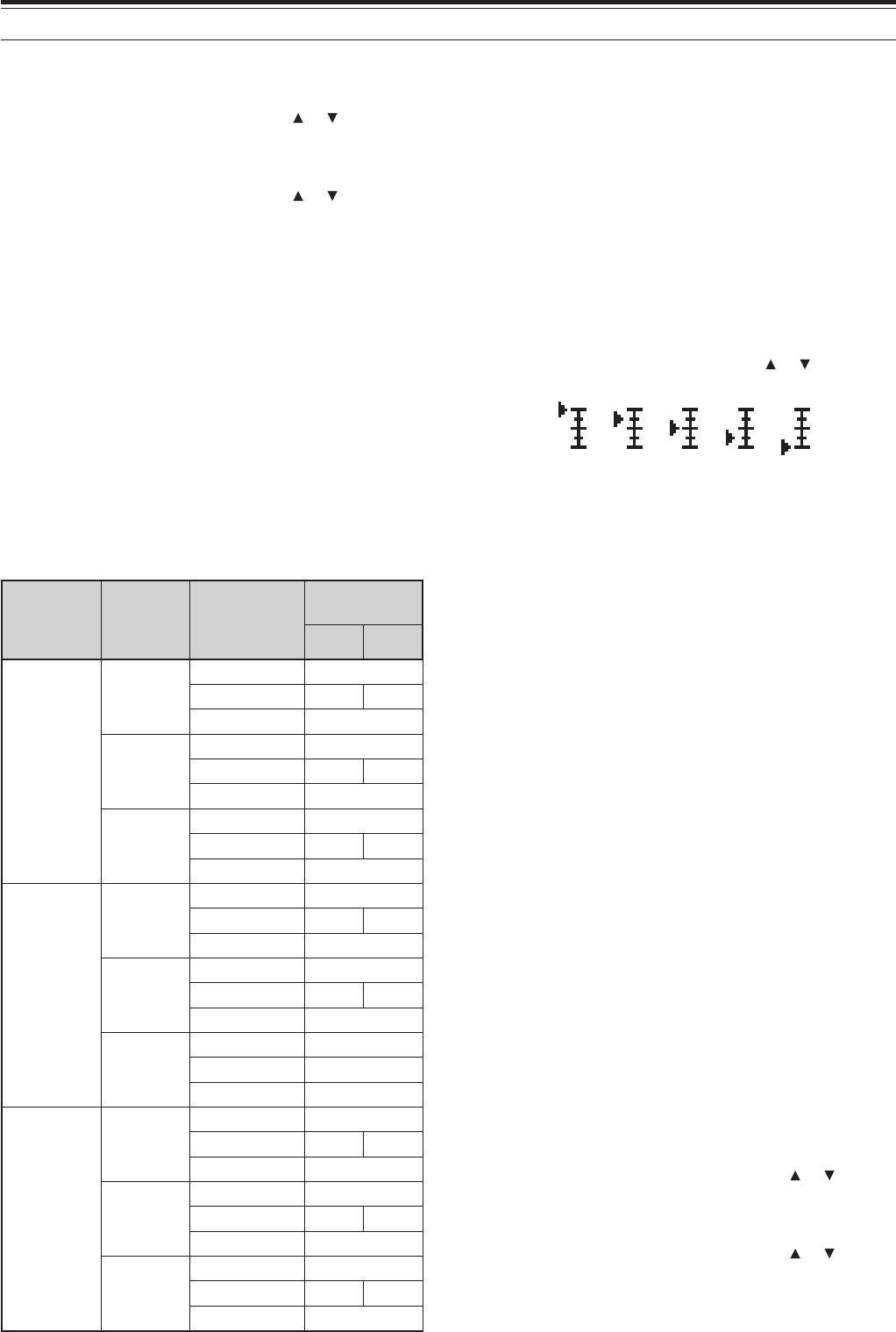
42
15 OPERATOR CONVENIENCES
the transceiver.
1Press [MNU].
2Turn the Tuning control or press []/ [ ] to select
Menu No. 8 (TX INHIBIT).
3Press [ss
ss
s] or [MNU].
4Turn the Tuning control or press []/ [ ] to select
“ON”.
5Press [ss
ss
s] or [MNU] to store the setting.
• “TX INHIBIT!” appears if you press [PTT] while
the TX Inhibit is ON.
TX POWER
You can change the transmission output power by
pressing [LOW]. Each time you press [LOW], the
icon cycles H ➞ L ➞ EL, and then goes back to H.
The output power varies depending on the battery
type and operating voltage. When the transceiver
operates with the power from the DC IN jack at 13.8
V DC, it produces the maximum output power. The
table below is approximate output power when the
transceiver operates with different types of battery or
DC power source.
tuptuO leveLrewoP yrettaB epyT dnaB
rewoPtuptuO ).xorppa(
A6F-HT E7F-HT
H)hgih(
41-TB )V0.6(
zHM441W7.1
zHM022W0.2A/N
zHM044/034W5.2
L24-BP )V4.7(
zHM441
zHM022
zHM044/034
NICD )V8.31(
zHM441
zHM022
zHM044/034
L)wol(
41-TB )V0.6(
zHM441
zHM022
zHM044/034
L24-BP )V4.7(
zHM441
zHM022
zHM044/034
NICD )V8.31(
zHM441
zHM022
zHM044/034
LE cimonoce( )wol
41-TB )V0.6(
zHM441
zHM022
zHM044/034
L24-BP )V4.7(
zHM441
zHM022
zHM044/034
NICD )V8.31(
zHM441
zHM022
zHM044/034
VOLUME BALANCE
While you are receiving A and B-bands at the same
time, you may sometimes feel that audio output on
either band is too loud. You can adjust the volume
balance level of the bands.
1Press [BAL].
• The balance scale and blinking cursor appear.
2Turn the Tuning control or press [ ]/ [ ] to
change the volume balance level of the bands.
A-band Max Max Max Att Mute
B-band Mute Att Max Max Max
Max: Maximum, Mute: Muted, Att: Attenuated
3Press [ss
ss
s] or [MNU] to store the setting.
VOX (VOICE-OPERATED TRANSMIT)
VOX eliminates the necessity of manually switching
to the transmit mode each time you want to transmit.
The transceiver automatically switches to transmit
mode when the VOX circuitry senses that you have
begun speaking into the microphone.
When using VOX, develop the habit of pausing
between thoughts to allow the transceiver to drop
back to receive mode briefly. You will then hear if
anybody wants to interrupt, plus you will have a short
period to gather your thoughts before speaking again.
Your listeners will appreciate your consideration as
well as respect your more articulate conversation.
VOX can be switched ON and OFF independently for
CW and the other modes, excluding FSK.
1Press [F], [SQL].
•“VOX” appears.
• To exit the VOX mode, press [F], [SQL] again.
■Microphone Input Level
To enjoy the VOX function, take the time to
properly adjust the gain of the VOX circuit. This
level controls the capability of the VOX circuit to
detect the presence or absence of your voice.
1Press [MNU].
2Turn the Tuning control or press []/ [ ] to
access Menu No. 21 (VOX GAIN).
3Press [ss
ss
s] or [MNU].
4Turn the Tuning control or press []/ [ ] to
select the “ON”.
5Press [ss
ss
s] or [MNU] to store the setting.
6While speaking into the microphone using your

43
15 OPERATOR CONVENIENCES
normal tone of voice, adjust the setting (default
is 4) using the Tuning control or press []/ [ ]
until the transceiver reliably switches to
transmit mode each time you speak.
• The selectable gain range is from 0 (least
sensitive) to 9 (most sensitive).
• The setting should not allow background
noise to switch the transceiver to transmit
mode.
Note: The VOX gain level can be adjusted even if VOX is
switched OFF or while you are transmitting.
■Delay Time
If the transceiver returns to receive mode too
quickly after you stop speaking, your final word
may not be transmitted. To avoid this, select an
appropriate delay time that allows all of your
words to be transmitted without an overly long
delay after you stop speaking.
1Press [MNU].
2Turn the Tuning control or press []/ [ ] to
select Menu No. 22 (VOX DELAY).
3Press [ss
ss
s] or [MNU].
4Turn the Tuning control or press []/ [ ] to
select the desired delay time from 100/ 200/
300/ 500 (default)/ 1000/ 1500/ 3000 ms.
5Press [ss
ss
s] or [MNU] to store the setting.
■VOX on Busy
You can configure the transceiver to enforce the
VOX transmission even if the A and/or B-band
receiver is receiving the signals.
1Press [MNU].
2Turn the Tuning control or press []/ [ ] to
select Menu No. 20 (VOXonBUSY).
3Press [ss
ss
s] or [MNU].
4Turn the Tuning control or press []/ [ ] to
select “ON”.
• To supress the VOX transmission when the
transceiver is receiving the signals, select
“OFF”.
5Press [ss
ss
s] or [MNU] to store the setting.
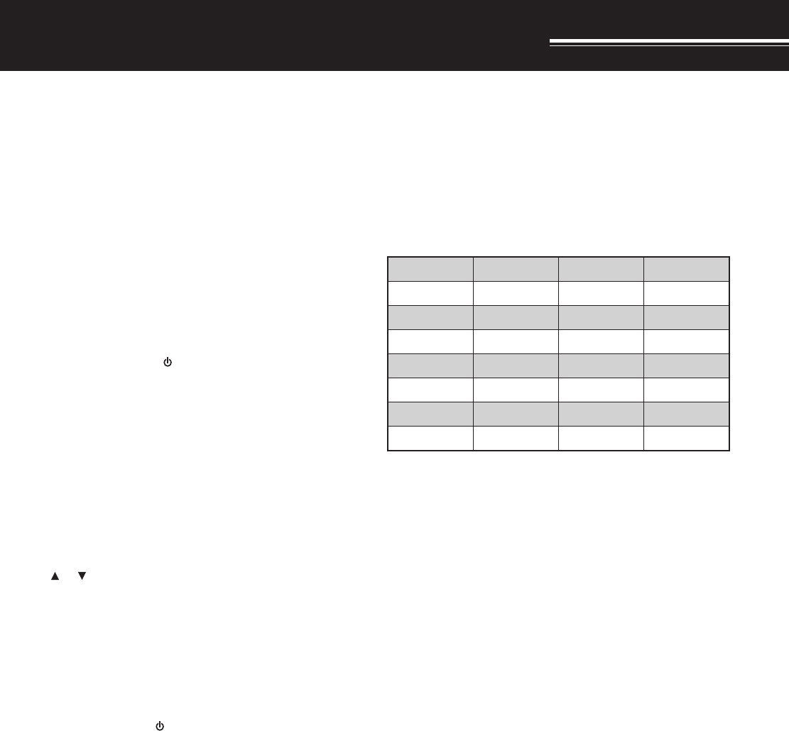
47
WIRELESS REMOTE CONTROL (TH-F6A ONLY)
If you also have a KENWOOD multi-band mobile
transceiver, you can control one of its bands by
sending DTMF tones from this handy transceiver.
You will find this function useful when you want to
control your mobile transceiver from a location
outside your vehicle.
Note:
◆
You can remotely control only the mobile transceivers that have
both the DTSS and Remote Control functions.
◆
The FCC rules permit you to send control codes only on the 440
MHz band.
PREPARATION
Let us assume the 144 MHz band of the mobile
transceiver will be controlled.
On the handy transceiver:
1Press [PTT]+[VFO]+[ ].
• The current secret access code number
appears. The default is 000.
2Press a numeric key 0 to 9 to enter a 3-digit secret
number.
• You can also turn the Tuning control or press
[ ]/ [ ] to select each digit. Press [ss
ss
s] ([tt
tt
t])
to move the cursor to the next (previous) digit.
3When the cursor on the most right position, press
[ss
ss
s] to complete the setting.
4Select the 440 MHz band.
5Select the transmit frequency.
6Turn the transceiver power OFF.
7Press [PTT]+[MR]+[ ].
• The transceiver enters Remote Control mode.
“MOBILE CTRL” appears.
• To exit Remote control mode, repeat steps 6
and 7.
On the mobile transceiver:
8Program the DTSS code on the UHF band as the
secret number.
• Select the same number as you selected in
step 2.
• For the programming method, refer to the
instruction manual for the mobile transceiver.
9Select the receive frequency on the UHF band.
• Mate this frequency with the transmit frequency
on the handy transceiver.
10 Make the transceiver enter Remote Control mode.
• For the method, refer to the instruction manual
for the mobile transceiver.
CONTROL OPERATION
When in the Remote Control mode, the keys of the
transceiver will function as below. Each time you
press a key, the transceiver will automatically enter
transmit mode and send the corresponding command
to the mobile transceiver.
1 2 3 A
NOVERNOENOTNOSSCTCTNE
4 5 6 B
FFOVERFFOENOTFFOSSCTCLESENOT
7 8 9 C
LLACOFVRM)NOPER(
0 D
NWODWOLPU)FFOPER(
1TM-V7A/ TM-D700A: REV ON/ OFF
Other mobile transceiver: TONE ALERT ON/ OFF
2Switches Repeater function ON/ OFF if the mobile
transceiver support this function.
To change the transmit/ receive frequency:
[VFO] ➡ [ENT] ➡ [0] ~ [9] (enter the necessary
digits) ➡ [ENT]) or [VFO] ➡ [UP]/ [DOWN]
To recall a memory channel:
[MR] ➡ [ENT] ➡ [0] ~ [9] (enter the necessary digits)
➡ [ENT] or [MR] ➡ [UP]/ [DOWN]
To change the tone (or CTCSS) frequency:
[TONE SEL] ➡ [0] ~ [9] (enter 2 digits; ex. [0], [5]) ➡
[TONE SEL]
• Refer to the Tone frequency table on your mobile
transceiver for the Tone number.
• Your mobile transceiver may require you to first
activate the Tone or CTCSS function. It may also
allow you to program a separate tone and CTCSS
frequency. Check the instruction manual for the
mobile transceiver.
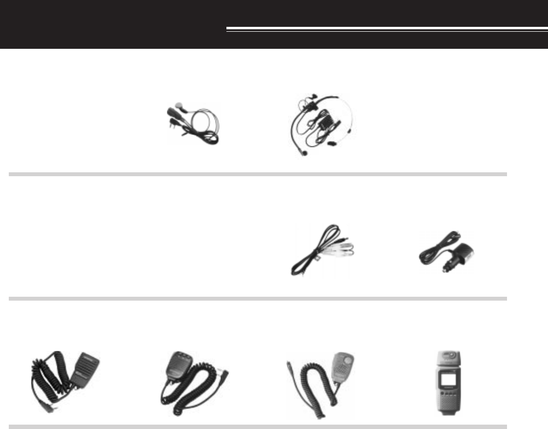
52
OPTIONAL ACCESSORIES
PG-2W
DC Cable
PG-3J
Filtered Cigarette Lighter
Cable
HMC-5
Headset
PB-42L
Li-ion Battery Pack
HMC-3
Headset with VOX/ PTT
EMC-3
Clip Microphone
HS-9
Earphone
SMC-33
Remote Control Speaker
Microphone
VC-H1
Interactive Visual
Communicator
SMC-32
Speaker Microphone
BT-13
Drycell Battery Case
SMC-34
Remote Control Speaker
Microphone (with VOL
control)