Kenwood USA 322602 UHF-FM Portable transceiver User Manual Manual
Kenwood USA Corporation UHF-FM Portable transceiver Manual
UserManual.wiki
>
Kenwood USA
>
322602 User Manual
Manual
Navigation menu
Upload a User Manual
Namespaces
Wiki Guide
HTML
PDF
Info
Views
User Manual
Discussion / Help
Navigation
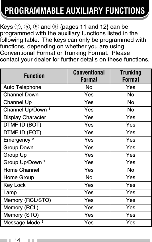
![33AUDIBLE USER FEEDBACK TONESThe transceiver emits various tones to indicate thetransceiver’s operating status. Contact your dealer forfurther information on these tones.enoT lanoitnevnoCtamroFgniknurTtamroFtrelAseYseYysuBseYseYyaleDoNseYyneDoNseYrotacoLfonoitaruDseYseY/edoMkcaBgniRmetsySeerFedoMhcraeSmetsyS oNseYllaCpuorGseYseYllaClaudividnIseYseYtpecretnIoNseYrorrEtupnIyeKseYseY]A[sserPyeKseYseY]B[sserPyeKseYseY]C[sserPyeKseYseYtnemeergAdrowssaPseYseYNOrewoPseYseYtrelAerPseYoNdeecorPoNseYeueuQoNseYgnigniRoNseYrevOlloRseYseYhcraeSmetsySoNseYdnEhcraeSmetsySoNseY](https://usermanual.wiki/Kenwood-USA/322602/User-Guide-1130407-Page-38.png)