Kenwood USA 322602 UHF-FM Portable transceiver User Manual Manual
Kenwood USA Corporation UHF-FM Portable transceiver Manual
Manual

© B62-1476-30 (K)
09 08 07 06 05 04 03
INSTRUCTION MANUAL
VHF FM TRANSCEIVER
TK-2140
TK-3140
UHF FM TRANSCEIVER

i
WARNING:
EXPLOSIVE ATMOSPHERES (GASES, DUST, FUMES, etc.)
Tu rn off your transceiver while taking on fuel, or while parked in
gasoline service stations.
◆Government law prohibits the operation of unlicensed radio
transmitters within the territories under government control.
◆Illegal operation is punishable by fine and/or imprisonment
◆Refer service to qualified technicians only.
SAFETY: It is important that the operator is aware of
and understands hazards common to the operation of
any transceiver.
THANK YOU
We are grateful you chose KENWOOD for your land
mobile radio applications. We believe this easy-to-use
transceiver will provide dependable communications to
keep personnel operating at peak efficiency.
KENWOOD transceivers incorporate the latest in
advanced technology. As a result, we feel strongly that
you will be pleased with the quality and features of this
product.
MODELS COVERED BY THIS MANUAL
• TK-2140: VHF FM Transceiver
• TK-3140: UHF FM Transceiver
NOTICES TO THE USER

ii
One or more of the following statements may be
applicable:
ATTENTION (U.S.A. Only):
The RBRC Recycle seal found on KENWOOD
nickel-cadmium (Ni-Cd) battery packs indicates
KENWOOD’s voluntary participation in an industry
program to collect and recycle Ni-Cd batteries after
their operating life has expired. The RBRC program
is an alternative to disposing Ni-Cd batteries with
your regular refuse or in municipal waste streams,
which is illegal in some areas.
For information on Ni-Cd battery recycling in your area, call (toll free)
1-800-8-BATTERY (1-800-822-8837).
KENWOOD’s involvement in this program is part of our commitment
to preserve our environment and conserve our natural resources.
FCC WARNING
This equipment generates or uses radio frequency energy. Changes
or modifications to this equipment may cause harmful interference
unless the modifications are expressly approved in the instruction
manual. The user could lose the authority to operate this equipment
if an unauthorized change or modification is made.
INFORMATION TO THE DIGITAL DEVICE USER REQUIRED BY
THE FCC
This equipment has been tested and found to comply with the limits
for a Class B digital device, pursuant to Part 15 of the FCC Rules.
These limits are designed to provide reasonable protection against
harmful interference in a residential installation.
This equipment generates, uses and can generate radio frequency
energy and, if not installed and used in accordance with the
instructions, may cause harmful interference to radio communications.
However, there is no guarantee that the interference will not occur in a
particular installation. If this equipment does cause harmful
interference to radio or television reception, which can be determined
by turning the equipment off and on, the user is encouraged to try to
correct the interference by one or more of the following measures:
•Reorient or relocate the receiving antenna.
•Increase the separation between the equipment and receiver.
•Connect the equipment to an outlet on a circuit different from that
to which the receiver is connected.
•Consult the dealer for technical assistance.

iii
CONTENTS
UNPACKING AND CHECKING EQUIPMENT ................... 1
SUPPLIED ACCESSORIES ......................................... 1
PREPARATION .................................................. 2
BATTERY PACK PRECAUTIONS .................................... 2
INSTALLING/ REMOVING THE (OPTIONAL) RECHARGEABLE BATTERY
PACK OR ALKALINE BATTERY CASE ............................... 7
INSTALLING/ REMOVING ALKALINE BATTERIES ...................... 8
INSTALLING THE (OPTIONAL) ANTENNA ............................ 9
INSTALLING THE BELT CLIP ....................................... 9
INSTALLING THE COVER OVER THE UNIVERSAL CONNECTOR ......... 10
INSTALLING THE (OPTIONAL KMC-25) SPEAKER/ MICROPHONE ...10
GETTING ACQUAINTED .......................................11
DISPLAY ......................................................13
PROGRAMMABLE AUXILIARY FUNCTIONS ................14
OPERATION OVERVIEW.......................................16
TRUNKING FORMAT ............................................16
CONVENTIONAL FORMAT ........................................16
OPERATING BASICS ...........................................17
SWITCHING POWER ON/ OFF ..................................17
ADJUSTING THE VOLUME .......................................17
SELECTING A SYSTEM/ GROUP/ CHANNEL ........................17
TIME-OUT TIMER (TOT) .......................................18
TRUNKED OPERATION (Trunking Format) ..................19
PLACING A DISPATCH CALL .....................................19
RECEIVING A DISPATCH CALL ...................................19

iv
CONVENTIONAL OPERATION (Trunking Format) ...........20
TRANSMITTING .................................................20
RECEIVING ....................................................20
SYSTEM SCAN (Trunking Format) ...........................21
SCANNING TRUNKED SYSTEMS ..................................21
SCANNING CONVENTIONAL SYSTEMS .............................21
SCAN LOCKOUT ................................................22
SCAN REVERT .................................................22
GROUP SCAN (Trunking Format) ............................23
CONVENTIONAL OPERATION (Conventional Format) .....24
TRANSMITTING .................................................24
RECEIVING ....................................................24
SCAN (Conventional Format) ................................25
PRIORITY SCAN ................................................25
2-TONE SIGNALLING (Conventional Format) ..............26
FleetSync™: ALPHANUMERIC 2-WAY PAGING FUNCTION ... 27
KEY FUNCTIONS ...............................................27
SELCALL (SELECTIVE CALLING) .................................28
STATUS MESSAGE .............................................30
OPTIONAL SHORT MESSAGES FEATURE ..........................32
AUDIBLE USER FEEDBACK TONES ..........................33
1
UNPACKING AND CHECKING EQUIPMENT
Note: The following unpacking instructions are for use by your
KENWOOD dealer, an authorized KENWOOD service facility, or the
factory.
Carefully unpack the transceiver. We recommend that
you identify the items listed in the following table before
discarding the packing material. If any items are missing
or have been damaged during shipment, file a claim with
the carrier immediately.
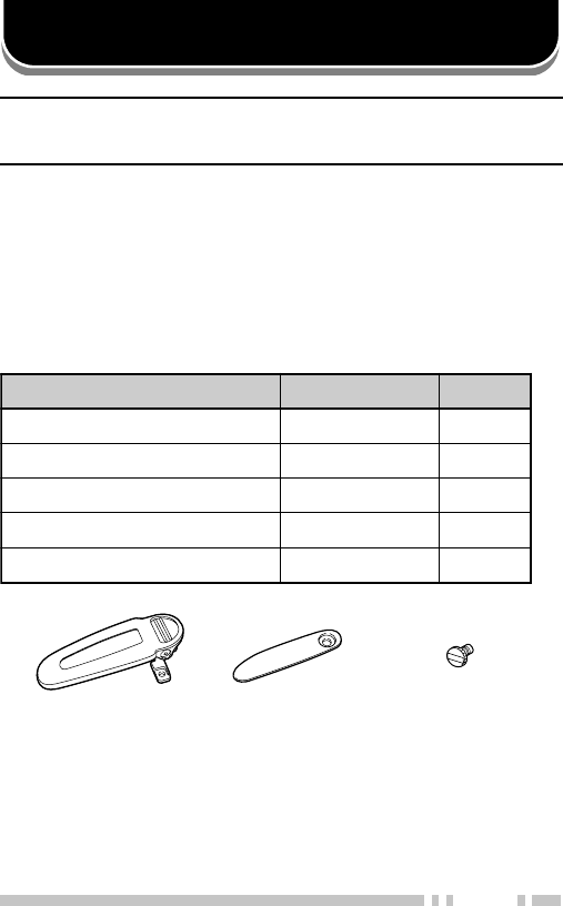
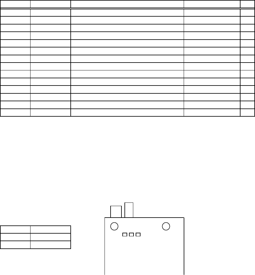
SUPPLIED ACCESSORIES
metI rebmuNtraP ytitnauQ
pilctleBXX-1070-92J1
pacrotcennoclarevinUXX-5260-90B1
wercsdesserDXX-8450-80N1
dracytnarraW—1
launamnoitcurtsnIXX-6741-26B1
Belt clip Universal
connector cap
Dressed
screw

2
BATTERY PACK PRECAUTIONS
◆Do not recharge the battery pack if it is already fully charged.
Doing so may cause the life of the battery pack to shorten or the
battery pack may be damaged.
◆After recharging the battery pack, disconnect it from the charger.
If the charger power is reset (turned ON after being turned OFF),
recharging will start again and the battery pack will become
overcharged.
◆Do not use the transceiver while charging the battery pack. We
recommend you switch the transceiver power OFF while charging
is taking place.
◆Do not short the battery terminals or dispose of the battery by
fire.
◆Never attempt to remove the casing from the battery pack.
Information concerning the (optional) Li-ion battery pack:
The battery pack includes flammable objects such as organic solvent.
Mishandling may cause the battery to rupture producing flames or
extreme heat, deteriorate, or cause other forms of damage to the
battery. Please observe the following prohibitive matters.
•Do not disassemble or reconstruct battery!
The battery pack has a safety function and protection circuit to
avoid danger. If they suffer serious damage, the battery may
generate heat or smoke, rupture, or burst into flame.
•Do not short-circuit the battery!
Do not join the + and – terminals using any form of metal (such as
a paperclip or wire). Do not carry or store the battery pack in
containers holding metal objects (such as wires, chain-neckless or
hairpins). If the battery pack is short-circuited, excessive current
will flow and the battery may generate heat or smoke, rupture, or
burst into flame. It will also cause metal objects to heat up.
PREPARATION
DANGER

3
•Do not incinerate or apply heat to the battery!
If the insulator is melted, the gas release vent or safety function is
damaged, or the electrolyte is ignited, the battery may generate
heat or smoke, rupture, or burst into flame.
•Do not use or leave the battery near fires, stoves, or other
heat generators (areas reaching over 80°C/ 176°F)!
If the polymer separator is melted due to high temperature, an
internal short-circuit may occur in the individual cells and the
battery may generate heat or smoke, rupture, or burst into flame.
•Do not immerse the battery in water or get it wet by other
means!
If the battery’s protection circuit is damaged, the battery may
charge at extreme current (or voltage) and an abnormal chemical
reaction may occur. The battery may generate heat or smoke,
rupture, or burst into flame.
•Do not charge the battery near fires or under direct sunlight!
If the battery’s protection circuit is damaged, the battery may
charge at extreme current (or voltage) and an abnormal chemical
reaction may occur. The battery may generate heat or smoke,
rupture, or burst into flame.
•Use only the specified charger and observe charging
requirements!
If the battery is charged in unspecified conditions (under high
temperature over the regulated value, excessive high voltage or
current over regulated value, or with a remodelled charger), it
may overcharge or an abnormal chemical reaction may occur.
The battery may generate heat or smoke, rupture, or burst into
flame.
•Do not pierce the battery with any object, strike it with an
instrument, or step on it!
This may break or deform the battery, causing a short-circuited.
The battery may generate heat or smoke, rupture, or burst into
flame.
•Do not jar or throw the battery!
An impact may cause the battery to leak, generate heat or smoke,
rupture, and/or burst into flame. If the battery’s protection circuit is
damaged, the battery may charge at an abnormal current (or
voltage), and an abnormal chemical reaction may occur. The
battery may generate heat or smoke, rupture, or burst into flame.

4
•Do not use the battery pack if it is damaged in any way!
The battery may generate heat or smoke, rupture, or burst into
flame.
•Do not solder directly onto the battery!
If the insulator is melted or the gas release vent or safety function
is damaged, the battery may generate heat or smoke, rupture, or
burst into flame.
•Do not reverse the battery polarity (and terminals)!
When charging a reversed battery, an abnormal chemical
reaction may occur. In some cases, an unexpected large amount
of current may flow upon discharging. The battery may generate
heat or smoke, rupture, or burst into flame.
•Do not reverse-charge or reverse-connect the battery!
The battery pack has positive and negative poles. If the battery
pack does not smoothly connect with a charger or operating
equipment, do not force it; check the polarity of the battery. If the
battery pack is reverse-connected to the charger, it will be
reverse-charged and an abnormal chemical reaction may occur.
The battery may generate heat or smoke, rupture, or burst into
flame.
•Do not touch a ruptured and leaking battery!
If the electrolyte liquid from the battery gets into your eyes, wash
your eyes out with fresh water as soon as possible, without
rubbing your eyes. Go to the hospital immediately. If left
untreated, it may cause eye-problems.

5
•Do not charge the battery for longer than the specified time!
If the battery pack has not finished charging even after the
regulated time has passed, stop it. The battery may generate
heat or smoke, rupture, or burst into flame.
•Do not place the battery pack into a microwave or high
pressure container!
The battery may generate heat or smoke, rupture, or burst into
flame.
•Keep ruptured and leaking battery packs away from fire!
If the battery pack is leaking (or the battery emits a bad odor),
immediately remove it from flammable areas. Electrolyte leaking
from battery can easily catch on fire and may cause the battery to
generate smoke or burst into flame.
•Do not use an abnormal battery!
If the battery pack emits a bad odor, appears to have different
coloring, is deformed, or seems abnormal for any other reason,
remove it from the charger or operating equipment and do not
use it. The battery may generate heat or smoke, rupture, or burst
into flame.
■Using the Li-ion Battery Pack
•Charge the battery pack before using it.
•To keep the battery discharge at a minimum, remove
the battery pack from the equipment when it is not in
use. Store the battery pack in a cool and dry location.
•When storing the battery pack for a long period:
1Remove the battery pack from the equipment.
2Discharge the battery pack, if possible.
3Store the battery pack in a cool (below 25°C/ 77°F)
and dry location.

6
■Characteristics of the Li-ion Battery Pack
•As the battery pack is charged and discharged
repeatedly, the battery capacity decreases.
•Even if the battery pack is unused, the battery pack
degrades.
•It takes a longer time to charge the battery pack in
cooler areas.
•The life of battery pack is shortened when it is charged
and discharged in hotter areas. When the battery pack
is stored in a hot location, the battery pack degrades
quicker. Do not leave the battery pack in vehicles or
near heating appliances.
•When the battery pack operating time becomes short,
even if it is fully charged, replace the battery pack.
Continuing to charge and discharge the battery pack
may result in elecrolyte leakage.
■Charging the Li-ion Battery Pack
When charging a transceiver with a Li-ion battery
pack, the safety catch of the battery pack may stick
out past the battery. When inserting the transceiver
with the battery pack into the charger, the safety
catch will touch the metal contacts of the charger
and the charger LED will momentarily light red. Be
sure to push the transceiver fully into the battery
pack slot so the safety catch no longer touches the
charger terminals. Once in place, the battery pack
will begin charging.
For charging procedures, refer to the charger
Instruction Manual.
7
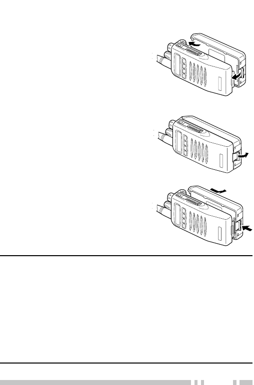
INSTALLING/ REMOVING THE (OPTIONAL) RECHARGEABLE BATTERY
PACK OR ALKALINE BATTERY CASE
1Match the guides of the
battery pack with the
corresponding grooves on
the upper rear of the
transceiver, then firmly press
the battery pack to lock it in
place.
2Flip the safety catch into
place to prevent accidentally
pressing the release latch
and removing the battery.
3To remove the battery pack,
lift the safety catch, press the
release latch, then pull the
battery pack away from the
transceiver.
Note:
◆To lift the battery pack safety catch, use a piece of hardened
plastic or metal, such as a screwdriver, that is no more than
6 mm wide and 1 mm thick. It is imperative that you place the
implement under only the lip of the safety catch so that you do
not damage the release latch.
◆Before charging a battery pack that is attached to the transceiver,
ensure that the safety catch is firmly closed.
◆While operating the transceiver using a Li-ion or Ni-MH battery
pack in areas with an ambient temperature of –10°C/ +14°F and
lower, operating time may be shortened.
8
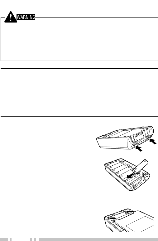
INSTALLING/ REMOVING ALKALINE BATTERIES
◆Do not install batteries in a hazardous environment where sparks
could cause an explosion.
◆Never discard old batteries in fire; extremely high temperatures
can cause batteries to explode.
◆Do not short circuit the battery case terminals.
◆Do not use commercially available rechargeable batteries.
Note:
◆If you do not plan to use the transceiver for a long period, remove
the batteries from the battery case.
◆This battery case has been designed for transmitting at a power
of approximately 1 W (the low power setting on your transceiver).
If you want to transmit a stronger signal (using the high power
setting on your transceiver), use an optional rechargeable battery
pack.
1To open the battery case,
press on the two tabs on the
upper rear of the case then
pull the two halves apart.
2Insert 6 AA (LR 6) alkaline
batteries into the battery
case.
•Be sure to match the
polarities with those marked
in the bottom of the battery
case.
3Align the tabs of the cover
with the base, then push
down on the cover until it
locks in place.
9
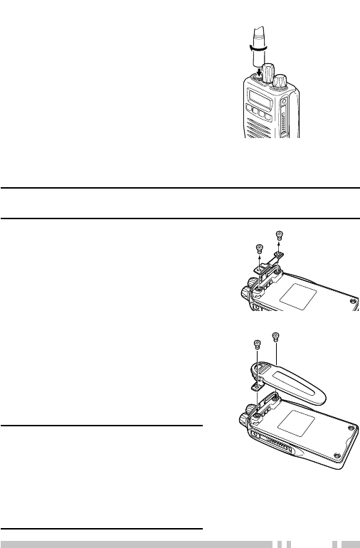
Screw the antenna into the
connector on the top of the
transceiver by holding the
antenna at its base and turning
it clockwise until secure.
INSTALLING THE (OPTIONAL) ANTENNA
INSTALLING THE BELT CLIP
Note: When first installing the belt clip, you must remove the battery
pack from the rear of the transceiver.
1Remove the two screws
from the rear of the
transceiver, then remove the
small, plastic black covering
that was held in place.
2Insert the belt clip mount
into the space on the rear of
the transceiver.
3Using the 2 screws, affix the
belt clip in place.
Note: Do not dispose of the plastic
black covering! If you remove the
belt clip, replace the covering into the
space on the rear of the transceiver.
Either this covering or the belt clip
must be in place, otherwise the
battery pack may not remain installed
properly.
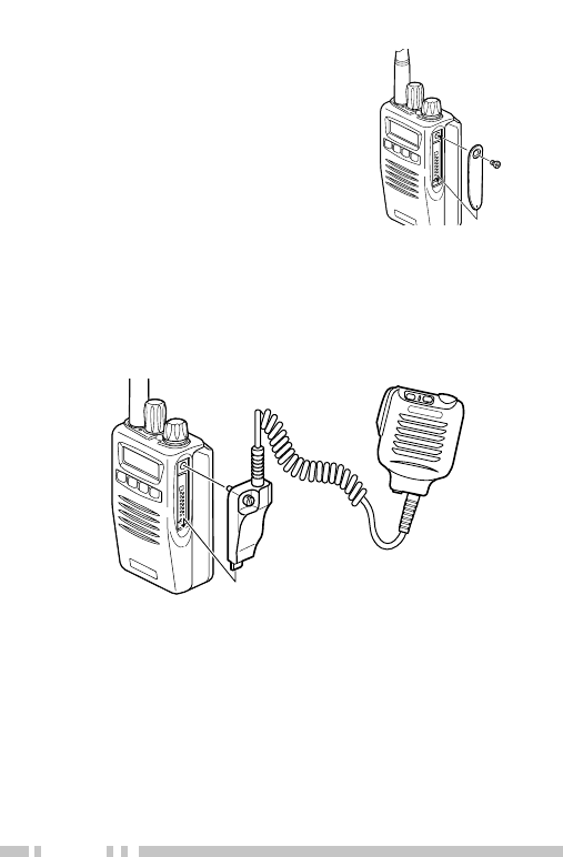
10
If you are not using the optional
KMC-25 speaker/ microphone,
install the cover over the
univeral connector using the
supplied 4 x 6 mm dressed
screw.
INSTALLING THE COVER OVER THE UNIVERSAL CONNECTOR
INSTALLING THE (OPTIONAL KMC-25) SPEAKER/ MICROPHONE
1Insert the guide of the speaker/ microphone
connector into the groove of the universal connector.
2Secure the connector in place using the attached
screw.
11
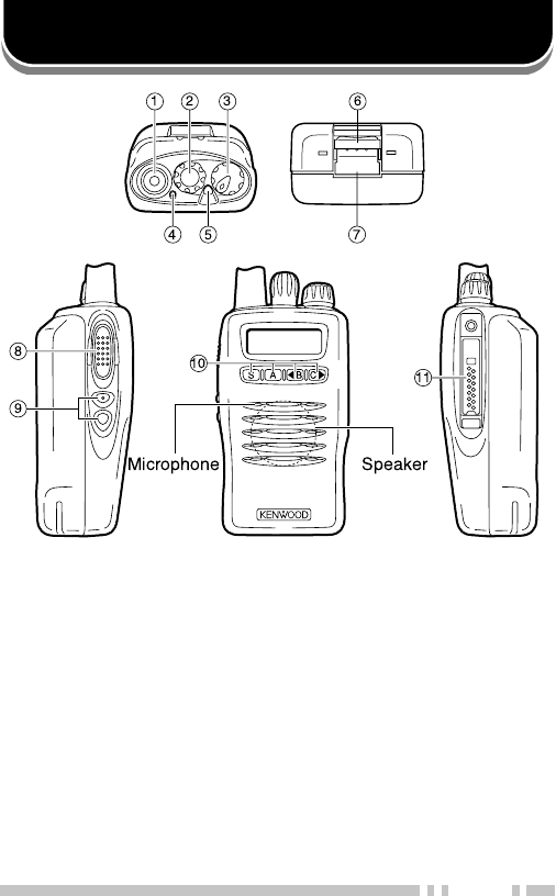
GETTING ACQUAINTED
qq
qq
qAntenna connector
Connect an (optional) antenna here.
ww
ww
wRotary encoder
Rotate this encoder to activate its programmable
function. (System or Group Up/ Down in Trunking
Format, and Group or Channel Up/ Down in
Conventional Format.) For further details, contact
your dealer.
ee
ee
ePOWER switch/ VOLUME control
Tu rn clockwise to switch ON the transceiver. Rotate
to adjust the volume. Turn counterclockwise fully to
switch OFF the transceiver.

12
rr
rr
rLED indicator
This LED lights red during transmission and green
while receiving a signal. During Sel Call Alert, the
LED flashes orange. If programmed by your dealer,
when the battery pack power is low, the LED flashes
red during transmission. Replace or recharge the
battery pack at this time.
Note: While operating the transceiver using a Li-ion battery pack,
the battery low indication time may be much shorter than when
using other battery packs. The transceiver power may suddenly
switch OFF at any time after the LED has started to flash.
tt
tt
tAuxiliary (orange) key
Press to activate its auxiliary function {page 14}.
yy
yy
yBattery pack safety catch
Flip this catch to prevent accidentally pressing the
battery pack release latch. See “INSTALLING/ REMOVING
THE (OPTIONAL) RECHARGEABLE BATTERY PACK OR ALKALINE
BATTERY CASE” on page 7.
uu
uu
uBattery pack release latch
Press this latch to release the battery pack. See
“INSTALLING/ REMOVING THE (OPTIONAL) RECHARGEABLE
BATTERY PACK OR ALKALINE BATTERY CASE” on page 7.
ii
ii
iPTT (Push-To-Talk) switch
Press this switch, then speak into the microphone to
call a station.
oo
oo
oSide 1 and Side 2 keys
Press to activate their auxiliary functions {page 14}.
!0!0
!0!0
!0 S, A, tt
tt
tB, and Css
ss
s keys
Press to activate their auxiliary functions {page 14}.
!1!1
!1!1
!1 Universal connector
Connect the (optional KMC-25) speaker/ microphone
here. Otherwise, keep the supplied cover in place.
13
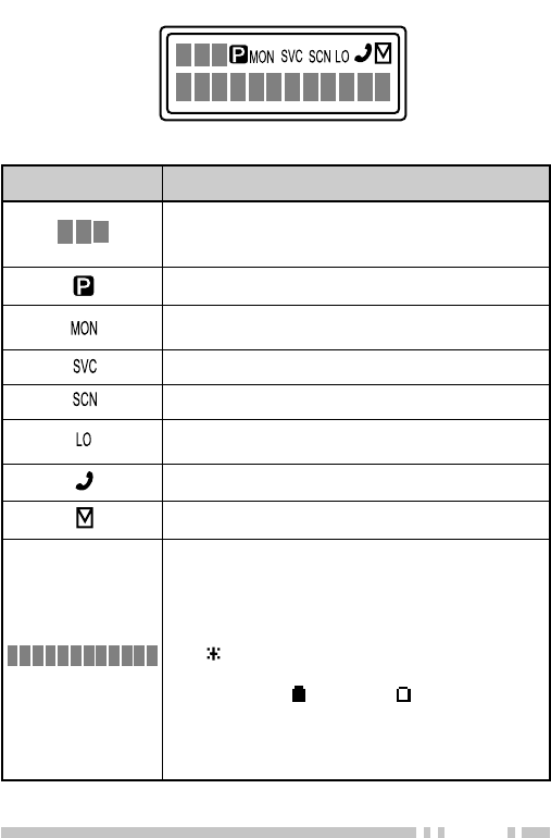
DISPLAY
rotacidnI noitpircseD
nirebmunpuorgrolennahcehtsyalpsiD
puorgrometsysehtdnatamroflanoitnevnoc
.tamrofgniknurtnirebmun
.nacSytiroirPgnimrofrepnehwsraeppA
sademmargorpyekehtnehwsraeppA rotinoM si
.desserp
.reviecsnartsihtnodesutonsinocisihT
.nacSgnimrofrepnehwsraeppA
sademmargorpyekehtnehwsraeppA rewoPFR
woL .desserpsi
.metsysenohpeletehtgnisuelihwsraeppA
.egassemaevahuoynehwsraeppA
puorg/metsysehtroemanpuorgehtsyalpsiD
stigid2gniniamerehT.stigid01otpuhtiwrebmun
ehT.srotacidnisuoiravgniwollofehtrofdesuera
rotacidnieteledasadesusitnemgestsomtfel
(▼evitceleSrofdesusitnemgestsomthgirehT.)
foleveletamixorppaehtyalpsidotro)(llaC
rotacidniyrettabehT.gniniamerrewopyrettab
.spets4ni)(ytpmeot)(llufmorfsegnar
:etoN afoecalpniseirettabenilaklagnisunehW
ylreporptonyamrotacidniyrettabeht,kcapyrettab
.gniniamerrewopyrettabehtetacidni

14
PROGRAMMABLE AUXILIARY FUNCTIONS
Keys w, t, o and !0 {pages 11 and 12} can be
programmed with the auxiliary functions listed in the
following table. The keys can only be programmed with
functions, depending on whether you are using
Conventional Format or Trunking Format. Please
contact your dealer for further details on these functions.
noitcnuF lanoitnevnoC
tamroF
gniknurT
tamroF
enohpeleTotuAoNseY
nwoDlennahCseYoN
pUlennahCseYoN
nwoD/pUlennahC
1
seYoN
retcarahCyalpsiDseYseY
)TOB(DIFMTDseYseY
)TOE(DIFMTDseYseY
ycnegremE
2
seYseY
nwoDpuorGseYseY
pUpuorGseYseY
nwoD/pUpuorG
1
seYseY
lennahCemoHseYoN
puorGemoHoNseY
kcoLyeKseYseY
pmaLseYseY
)OTS/LCR(yromeMseYseY
)LCR(yromeMseYseY
)OTS(yromeMseYseY
edoMegasseM
3
seYseY

15
noitcnuF lanoitnevnoC
tamroF
gniknurT
tamroF
yratnemoMrotinoMseYseY
elggoTrotinoMseYseY
enoNseYseY
enoTelbatceleSrotarepOseYoN
laideRseYseY
woLrewoPFRseYseY
nacSseYseY
ddA/leDnacSseYseY
eteleDyraropmeTnacSoNseY
noitaunettAPS
4
seYseY
leveLhcleuqSseYoN
yratnemoMffOhcleuqSseYseY
elggoTffOhcleuqSseYseY
nwoDmetsySoNseY
pUmetsySoNseY
nwoD/pUmetsyS
1
oNseY
dnuorAklaTseYoN
tcennocsiDenohpeleToNseY
1These functions can be programmed only on key w, the
encoder.
2This function can be programmed only on key t, the
Auxiliary (orange) key, and on the programmable function
key of the optional KMC-25 speaker/ microphone.
3This function can be programmed only on key !0’s A key.
4This function can be programmed only on the programmable
function key of the optional KMC-25 speaker/ microphone.

16
OPERATION OVERVIEW
Your dealer can program your transceiver for either
Tr unking Format or Conventional Format.
TRUNKING FORMAT
This format can handle up to 32 systems with up to 250
groups in each system. The transceiver can be used in
both trunked mode and conventional mode. Systems,
groups, and their functions are programmed by your
dealer.
CONVENTIONAL FORMAT
This format can handle up to 250 groups with 250
channels in each group. The transceiver can be used
only in conventional mode. Groups, channels, and their
functions are programmed by your dealer.

17
OPERATING BASICS
SWITCHING POWER ON/ OFF
Tu rn the Power switch/ Volume control clockwise to
switch the transceiver ON.
Tu rn the Power switch/ Volume control counterclock-
wise to switch the transceiver OFF.
ADJUSTING THE VOLUME
Rotate the Power switch/ Volume control to adjust the
volume. Clockwise increases the volume and counter-
clockwise decreases it.
SELECTING A SYSTEM/ GROUP/ CHANNEL
Select the desired system and group (Trunking Format)
using the encoder and the keys programmed with
System or Group Up/ Down.
Select the desired group and channel (Conventional
Format) using the encoder and the keys programmed
with Group or Channel Up/ Down.

18
TIME-OUT TIMER (TOT)
The purpose of the Time-out Timer is to prevent any
caller from using a channel for an extended period of
time.
If you continuously transmit for a period of time that
exceeds the programmed time, the transceiver will stop
transmitting and an alert tone will sound. To stop the
tone, release the PTT switch.
Your dealer can program the TOT time in the range of
15 seconds to 10 minutes.

19
TRUNKED OPERATION (Trunking Format)
PLACING A DISPATCH CALL
1Select the desired system and group using the
encoder and the System or Group keys.
2Press the PTT switch, then speak into the
microphone. Release the PTT switch to receive.
•For best sound quality at the receiving station, hold the
microphone approximately 1.5 inches (3 ~ 4 cm) from
your mouth.
RECEIVING A DISPATCH CALL
1Select the desired system and group using the
encoder and the System or Group keys. (If the
Scan function has been programmed, you can switch
it ON or OFF as desired.)
2When you hear the dispatcher’s voice, readjust the
volume as necessary.

20
CONVENTIONAL OPERATION (Trunking Format)
TRANSMITTING
1Select the desired system and group using the
encoder and the System or Group keys.
2Press the key programmed as Monitor to check
whether or not the channel is free.
•If the channel is busy, wait until it becomes free.
3Press the PTT switch and speak into the
microphone. Release the PTT switch to receive.
•For best sound quality at the receiving station, hold the
microphone approximately 1.5 inches (3 ~ 4 cm) from
your mouth.
RECEIVING
1Select the desired system and group using the
encoder and the System or Group keys. (If the
Scan function has been programmed, you can switch
it ON or OFF as desired.)
2When you hear the dispatcher’s voice, readjust the
volume as necessary.

21
SYSTEM SCAN (Trunking Format)
If the Scan function is programmed, systems can be
scanned by pressing the key programmed as Scan.
When the Scan key is pressed, the SCN indicator and
“-SCAN-” or the revert system/ group number, appear on
the display and scanning starts. The systems not locked
out of the scanning sequence are scanned.
When a call is received, scanning stops and the system
and group digits appear. Press the PTT switch and
speak into the microphone to respond to the call. The
transceiver will continue scanning after a predetermined
time delay if the PTT switch is released and no further
signal is received.
SCANNING TRUNKED SYSTEMS
When scanning trunked systems, the revert groups and
the groups not locked out of the scanning sequence are
scanned. See “GROUP SCAN” on page 23.
SCANNING CONVENTIONAL SYSTEMS
When scanning conventional systems, the revert groups
and the groups not locked out of the scanning sequence
are scanned. See “GROUP SCAN” on page 23.

22
SCAN LOCKOUT
If a programmable auxiliary key is programmed with
Scan Del/Add, each system can be locked out of the
scan sequence manually. The delete indicator ( s ) will
appear on the display when the selected system is
locked out.
SCAN REVERT
You can select revert systems and groups using the
encoder and the System or Group keys.
Six types of Scan Reverts which can be programmed by
your dealer are available:
•Last Called Revert: The last system/ group received is
assigned as the new revert system and group.
•Last Used Revert: The last system/ group responded to
is assigned as the new revert system and group.
•Selected: The last system/ group selected is assigned as
the new revert system and group.
•Selected + Talkback: If the system/ group has been
changed during Scan, the newly selected system/ group is
assigned as the new revert system and group. The
transceiver “talks back” on the current receive group.
•Priority: If your dealer has programmed a Priority
channel, this channel is the revert system and group.
•Priority + Talkback: If your dealer has programmed a
Priority channel, this channel is the revert system and
group. The transceiver “talks back” on the current receive
group.

23
GROUP SCAN (Trunking Format)
Group Scan is available for both trunked and
conventional systems. This feature is useful when more
than one group is programmed in a system. Group
Scan is set by your dealer on request. It scans the
revert groups as well as groups that are allowed to be
scanned.
When a call is received, the group indicator shows the
group number, and that group becomes the revert group.
Simply press the PTT switch to respond to the call.
You can also perform Group Scan while using a priority
channel. Please contact your dealer for information
concerning Priority Scan.

24
CONVENTIONAL OPERATION (Conventional Format)
TRANSMITTING
1Select the desired group and channel using the
encoder and the Group or Channel keys.
2Press the key programmed as Monitor to check
whether or not the channel is free.
•If the channel is busy, wait until it becomes free.
3Press the PTT switch and speak into the
microphone. Release the PTT switch to receive.
•For best sound quality at the receiving station, hold the
microphone approximately 1.5 inches (3 ~ 4 cm) from
your mouth.
RECEIVING
1Select the desired group and channel using the
encoder and the Group or Channel keys. (If the
Scan function has been programmed, you can switch
it ON or OFF as desired.)
2When you hear a caller’s voice, readjust the volume
as necessary.

25
SCAN (Conventional Format)
If the Scan function is programmed, groups or channels
can be scanned by pressing the key programmed as
Scan. Scan can be used as either Single Scan or Multi
Scan. Single Scan monitors only the channels of a
single group. Multi Scan monitors all channels of every
group. When the Scan key is pressed, the SCN
indicator and “-SCAN-” or the revert group/ channel
number, appear on the display and scanning starts.
When a call is received, scanning stops and the group
and channel digits appear. Press the PTT switch and
speak into the microphone to respond to the call. The
transceiver will continue scanning after an adjustable
time delay, if the PTT switch is released, and no further
signal is received.
When the displayed group is not locked out of the
scanning sequence, the add indicator ( ) will appear on
the display.
PRIORITY SCAN
The priority channel must be programmed in order for
Priority Scan to function.
The transceiver will automatically change to the priority
channel when a signal is received on it, even if a signal
is being received on a normal channel.
The indicator appears when the displayed channel is
the priority channel.

26
2-TONE SIGNALLING (Conventional Format)
2-Tone Signalling is either activated or deactivated by
your dealer.
2-Tone Signalling only opens the squelch when the
transceiver receives two tones corresponding to those
set up in the transceiver. When the squelch opens, you
will be able to hear the caller without any further action.
After a correct 2-Tone signal is received and the squelch
opens, pressing the key programmed as Monitor will
cancel the connection.
If your dealer programmed Transpond for 2-Tone
Signalling, your transceiver will automatically send an
acknowledgment signal to the station that called you
with the correct 2-Tone signal. Transpond does not
function when you are called as a Group call.
If your dealer programmed Tone Alert for 2-Tone
Signalling, your transceiver will emit a beep when the
correct 2-Tone signal is received.
Note: This transceiver is only capable of decoding 2-Tone Signals. It
cannot encode a 2-Tone Signal.
27
FleetSync™ is an Alphanumeric 2-way Paging Function,
and is a protocol owned by KENWOOD Corporation.
FleetSync™ enables a variety of paging functions on your
transceiver, some of which depend on dealer programming.
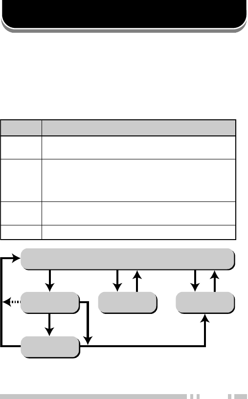
KEY FUNCTIONS
FleetSync™: ALPHANUMERIC 2-WAY PAGING FUNCTION
Selcall Mode *
Status Mode
Stack Mode
New Message
Display Mode
Normal Operating Mode
Press A
or receive
a Selcall
Receive
a new
message
Hold A for
1 second
Press
any key
Press
A
Press
A
Press A
Hold A for 1 second
yeK noitcnuF
AninwohssaedomreviecsnartehtegnahcotsserP
.wolebmargaideht
S
ehtneewtebelggototedoMkcatSnielihwsserP
dnasserP.DIs’rellacehtdnaegassemdeviecer
ehteteledotdnoces1nahteromrofdloh
.egassemdeyalpsid
tt
t
ttB,Css
s
ss .segassemdeviecergnillorcs-otuapotsotsserP
.yllaunamllorcsotsserposlA
TTP .llacaetaitiniotsserP
*Depending on how your dealer programmed the transceiver,
Selcall Mode may be skipped or the transceiver may exit Selcall
Mode automatically (as shown by the dash arrow).

28
SELCALL (SELECTIVE CALLING)
A Selcall is a voice call to a particular station or to a
group of stations.
■Transmitting
1Select your desired system and group (or group
and channel).
2Press the A key to enter Selcall Mode.
3Press the tt
tt
tB key or Css
ss
s key to select the ID of
the station you want to call.
4Press the PTT switch and begin your
conversation.
■Receiving
An alert tone will sound, the transceiver will
automatically enter Selcall Mode, and the calling
station’s ID will appear when a Selcall is received.
To respond to the call, press the PTT switch and
speak into the microphone.

29
■View the Caller IDs in the Stack Memory
If programmed by your dealer, the mail icon ( ) will
flash when a Selcall call is received and stacked.
1Press and hold the A key for more than 1 second
to enter Stack Mode.
•The last received Caller ID is displayed with the
Caller ID number. “I” (ID) appears with the number.
2Press the tt
tt
tB key or Css
ss
s key to select the ID you
want to view (if more than one ID is stored in the
stack memory).
3To erase the ID, press and hold the S key for
more than 1 second.
■Identification Codes
An ID code is a combination of a 3-digit Fleet
number and a 4-digit ID number. Each transceiver
must have its own Fleet and ID number.
•Enter a Fleet number (100 ~ 349) to make a group call.
•Enter an ID number (1000 ~ 4999) to make an
individual call in your fleet.
•Enter a Fleet number followed by an ID number to
make an individual call in your desired fleet
(Inter-fleet call).
•Select “ALL” Fleet and “ALL” ID to make a call to all
units (Broadcast call).
•Select “ALL” Fleet and enter an ID number to make a
call to the selected ID in all fleets (Supervisor call).
Note: The ID range may be limited by programming.

30
STATUS MESSAGE
You can send and receive 2-digit Status messages
(10 ~ 79) which may be decided in your talk group.
Messages can contain up to 16 alphanumeric
characters.
A maximum of 9 received messages can be stored in
the stack memory of your transceiver. These saved
messages can be reviewed after reception. If the stack
memory is full, the oldest message will be erased when
a new message is received. The mail icon ( ) lights
when a message is stored in the stack memory.
Note: All stored messages will be cleared when the transceiver
power is turned OFF.
■ Transmitting
1Select your desired system and group (or group
and channel).
2Press the A key to enter Selcall Mode.
3Press the tt
tt
tB key or Css
ss
s key to select the ID of
the station you want to call.
4Press the A key to enter Status Mode.
5Press the tt
tt
tB key or Css
ss
s key to select the status
you want to transmit.
6Press the PTT switch to initiate the Status call.
•“COMPLETE” is displayed when the call has been
successfully transmitted.

31
■Receiving
The mail icon ( ) will flash and a calling ID or text
message will appear when a Status call is received.
•The display alternates between the caller ID and the
message.
Press any key to return to Normal Operation Mode.
■Reviewing the Messages in the Stack Memory
1Press and hold the A key for more than 1 second
to enter Stack Mode.
•The last received message is displayed with the
message number. “S” (Status) appears with the
number.
2Press the tt
tt
tB key or Css
ss
s key to select the
message you want to view (if more than one
message is stored in the stack memory).
3Press the S key to toggle between the message
and the caller’s ID.
4To erase the message, press and hold the S key
for more than 1 second.

32
■Automatic Status Response
If you pre-select a status number and then leave the
transceier in Status Mode, the transceiver will
automatically respond with that status number when
a request from the base station is received. (The
base station request function is optional.)
OPTIONAL SHORT MESSAGES FEATURE
Received short messages (maximum of 48 characters)
are displayed the same as Status messages {page 29},
however only four (4) short messages can be stored in
the stack memory. “M” (Message) and the message
number appear with the message.

33
AUDIBLE USER FEEDBACK TONES
The transceiver emits various tones to indicate the
transceiver’s operating status. Contact your dealer for
further information on these tones.
enoT lanoitnevnoC
tamroF
gniknurT
tamroF
trelAseYseY
ysuBseYseY
yaleDoNseY
yneDoNseY
rotacoLfonoitaruDseYseY
/edoMkcaBgniRmetsySeerF
edoMhcraeSmetsyS oNseY
llaCpuorGseYseY
llaClaudividnIseYseY
tpecretnIoNseY
rorrEtupnIyeKseYseY
]A[sserPyeKseYseY
]B[sserPyeKseYseY
]C[sserPyeKseYseY
tnemeergAdrowssaPseYseY
NOrewoPseYseY
trelAerPseYoN
deecorPoNseY
eueuQoNseY
gnigniRoNseY
revOlloRseYseY
hcraeSmetsySoNseY
dnEhcraeSmetsySoNseY
Terminal Descriptions
Universal connector
It is possible to use a resin-based cover for the Universal connector.
NO. Name Description Impedance I/O
1 SSW Ext/Int Speaker Switch Input High Impedance I
2 SP+ BTL Output + for External Speaker 8 ΩO
3 SP- BTL Output - for External Speaker 16 ΩO
4 MSW Ext/Int MIC Switch Input High Impedance I
5 EMC External MIC Input 1.8 kΩI
6 ME External MIC GND GND -
7 PTT External PTT Input High Impedance I
8 PF Programable Function Key Input High Impedance I
9 NC Not used - -
10 E GND GND -
11 5M 5V power supply output 5V -
12 TXD Serial Data Output CMOS O
13 RXD Serial Data Input CMOS I
14 NC Not used - -
Antenna Terminal
50 Ω impedance
Battery Terminal
The battery terminal uses a spring plate.
The negative terminal connects to the chassis ground.
The battery is mounted on the rear and upper side of the transceiver using a sliding
mounting method.
1 Select
2-
3+ 123
Back side view
Radio FRequency eneRgy SaFety inFoRmation
This Kenwood transceiver has been tested and complies with the standards listed below, in regards
to Radio Frequency (RF) energy and electromagnetic energy (EME) generated by the transceiver.
• FCC RF exposure limits for
Occupational Use Only
. RF Exposure limits adopted by the FCC are generally
based on recommendations from the National Council on Radiation Protection and Measurements, & the
American National Standards Institute.
• FCC OET Bulletin 65 Edition 97-01 Supplement C
• American National Standards Institute (C95.1 – 1992)
• American National Standards Institute (C95.3 – 1992)
This Kenwood transceiver generates RF EME while transmitting. RF EME (Radio Frequency Electric &
Magnetic Energy) has the potential to cause slight thermal, or heating effects to any part of your body less
than the recommended distance from this radio transmitter’s antenna. RF energy exposure is determined
primarily by the distance to and the power of the transmitting device. In general, RF exposure is minimized
when the lowest possible power is used or transmission time is kept to the minimum required for consistent
communications, and the greatest distance possible from the antenna to the body is maintained. The
transceiver has been designed for and is classied for
Occupational Use Only
. Occupational/ controlled
exposure limits are applicable to situations in which persons are exposed to RF energy as a consequence
of their employment, and such persons have been made aware of the potential for exposure and can
exercise control over their exposure. This means you can use the transceiver only if you are aware of
the potential hazards of operating a transceiver and are familiar in ways to minimize these hazards. This
transceiver is not intended for use by the general public in uncontrolled environments. Uncontrolled
environment exposure limits are applicable to situations in which the general public may be exposed to RF
energy, or in which the persons who are exposed as a consequence of their employment may not be fully
aware of the potential for exposure or cannot exercise control over their exposure.
The following list provides you with the information required to ensure that you are aware of RF
exposure and of how to operate this transceiver so that the FCC RF exposure limitations are not
exceeded.
• While transmitting (holding the PTT switch or speaking with VOX enabled), always keep the antenna
and the radio at least 3 cm (1 3/16 inches) from your body or face, as well as from any bystanders. A
LED on the top of the radio shows red when the transmitter is operating in both PTT and VOX modes.
• Do not transmit for more than 50% of the total transceiver use time; transmitting over 50% of the total use
time may exceed the limits in accordance to the FCC RF exposure requirements. Nominal transceiver
operation is 5% transmission time, 5% reception time, and 90% stand-by time.
• Use only the specied antenna for this transceiver; this may be either the antenna provided with the
transceiver or another antenna authorized by Kenwood.
Use only Kenwood authorized accessories (antennas, battery packs, belt clips, Speaker/ Mics or
headsets etc.): When worn on the body, always place the radio in a Kenwood recommended clip or
carrying case meant for this product. The use of other than recommended or approved body- worn
accessories may result in RF exposure levels which exceed the FCC’s occupational/ controlled
environment RF exposure limits.
To ensure that your exposure to RF EME is within the FCC limits for occupational use, you must
observe and adhere to the above points.
Electromagnetic Interference Compatibility
Electronic devices are susceptible to electromagnetic interference (EMI) if they are not adequately
shielded or designed for electromagnetic compatibility. Because this transceiver generates RF
energy, it can cause interference to such equipment.
• Turn OFF your transceiver where signs are posted to do so. Hospitals and health care facilities use
equipment that is sensitive to electromagnetic radiation.
• Turn OFF your transceiver while on board an aircraft when so instructed. Use of the transceiver must
be in accordance with airline regulations and/or crew instructions. B59-2546-00