Kenwood USA 435002 UHF FM Transceiver User Manual User s Manual
Kenwood USA Corporation UHF FM Transceiver User s Manual
UserManual.wiki
>
Kenwood USA
>
435002 User Manual
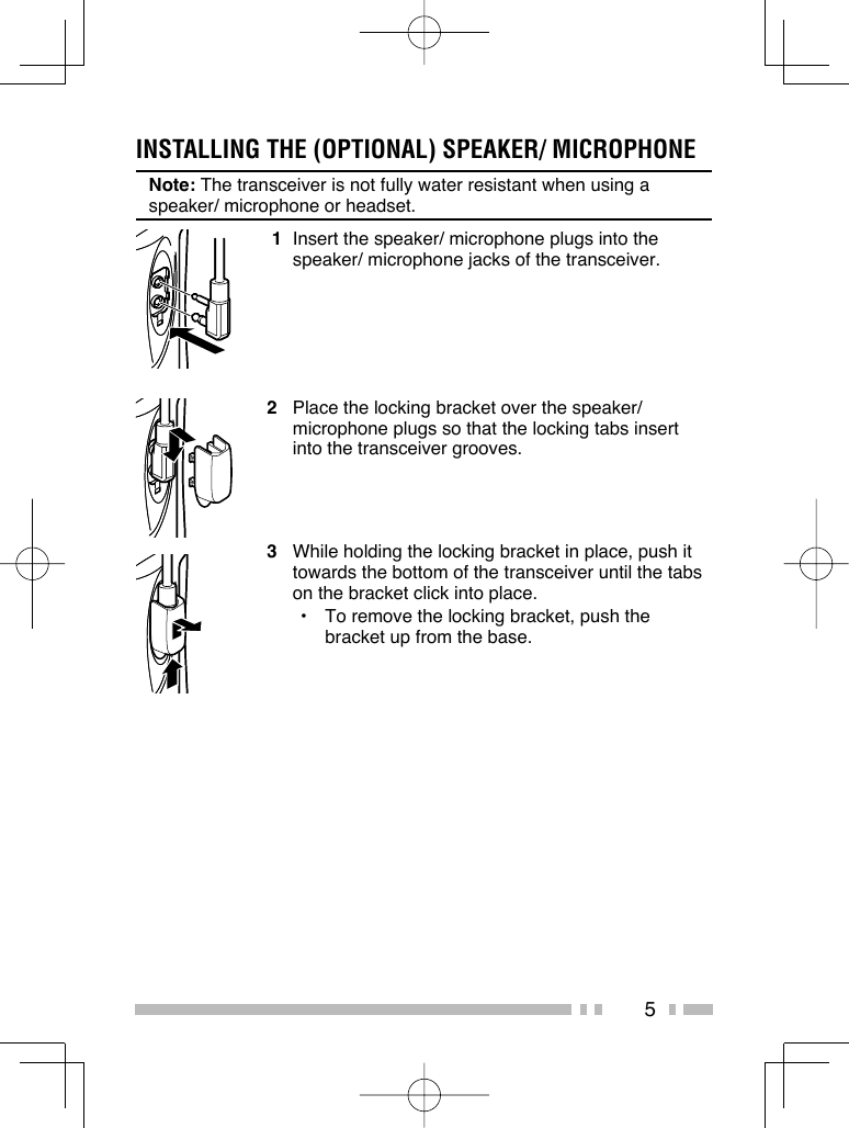
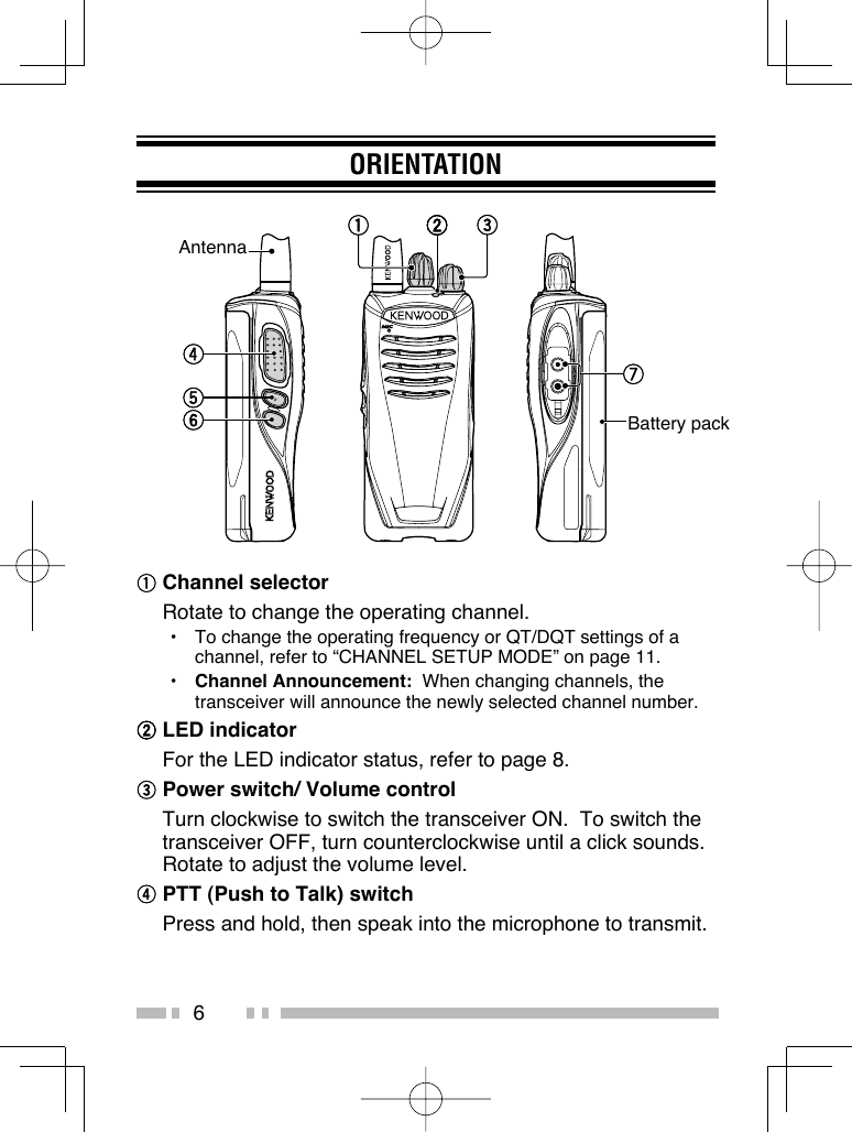
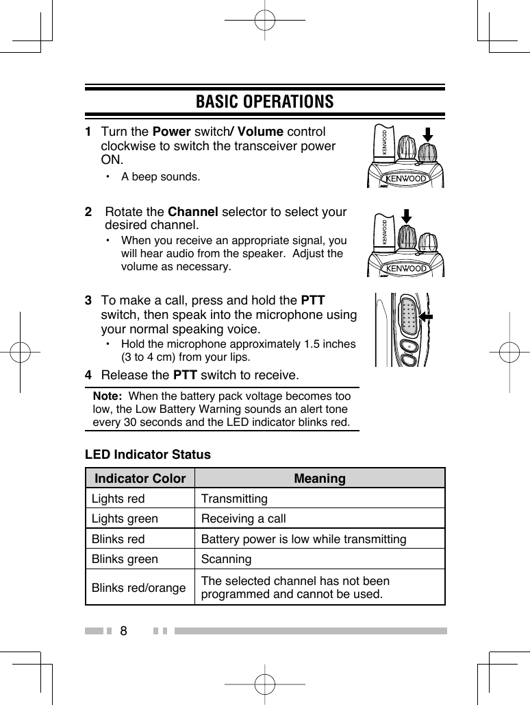
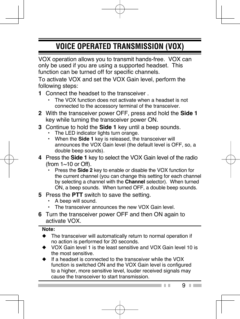
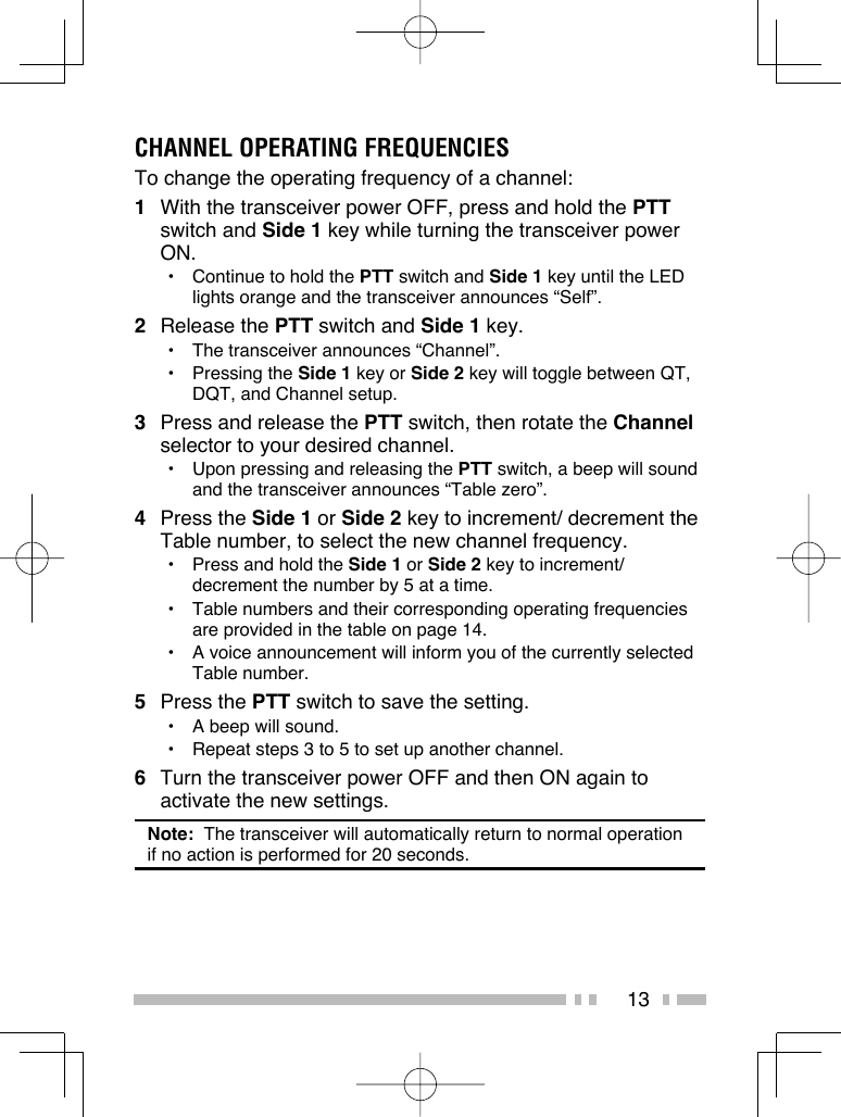
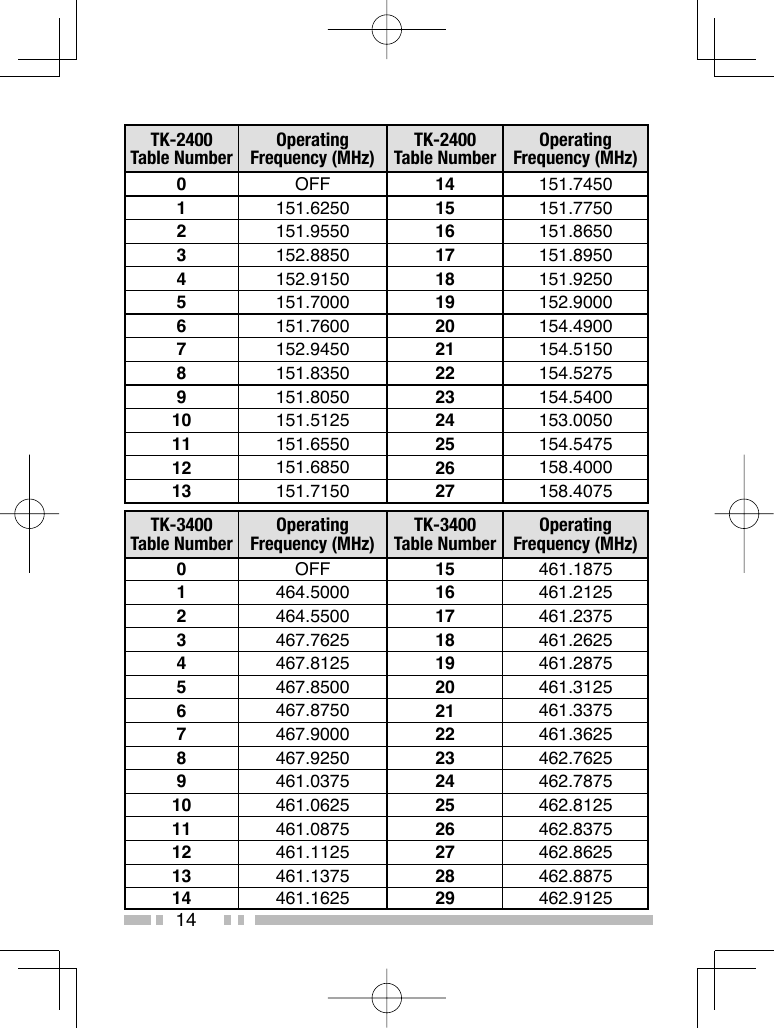
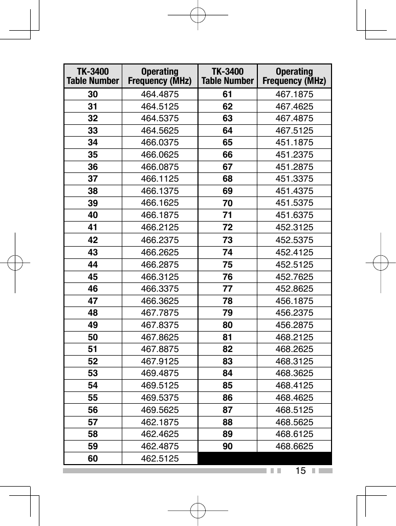
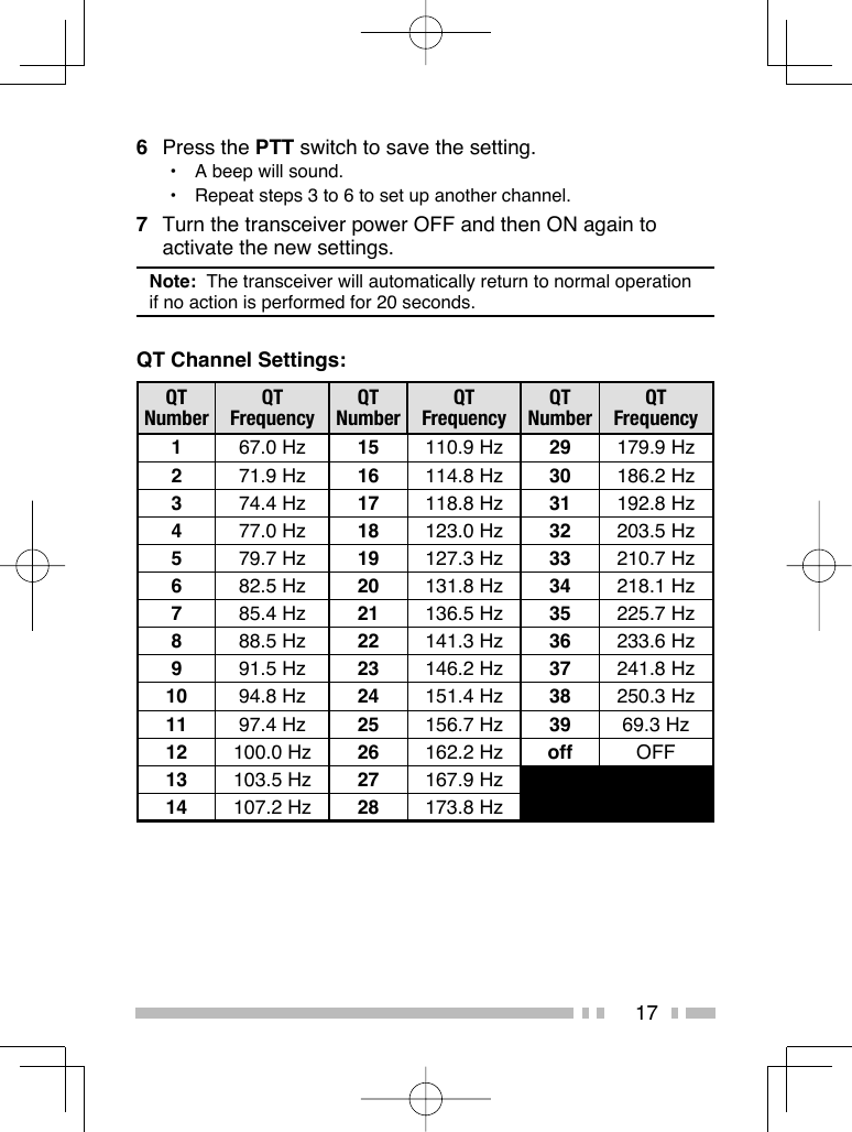
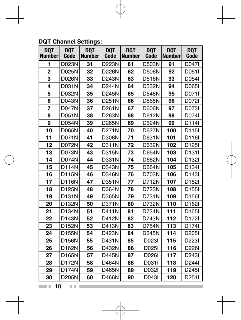
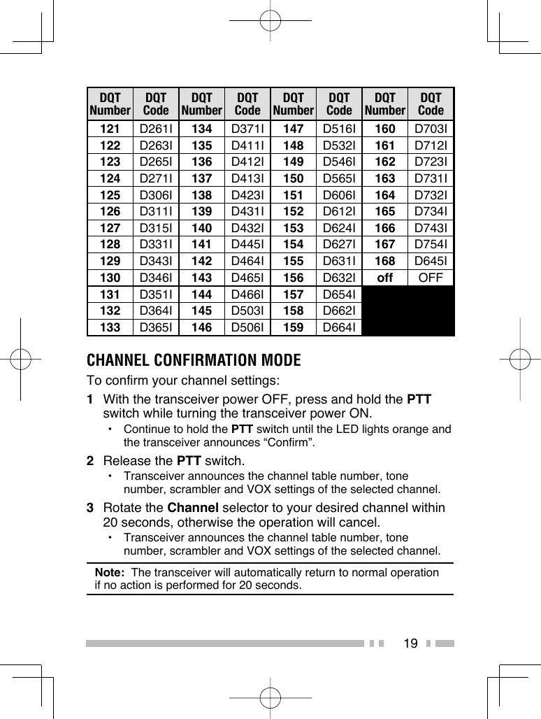
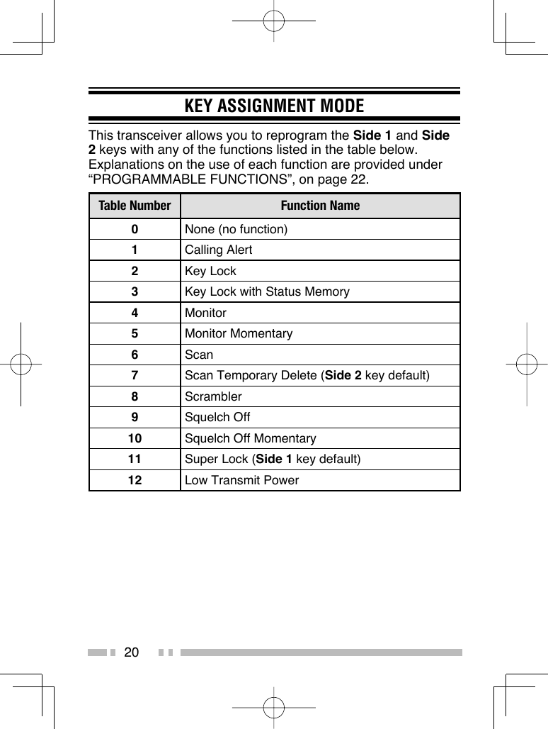
User's Manual
Navigation menu
Upload a User Manual
Namespaces
Wiki Guide
HTML
PDF
Info
Views
User Manual
Discussion / Help
Navigation