Kenwood Th G71A Users Manual G71A_E
TH-G71A to the manual 7fb9aee4-000f-41f0-a608-d10eea1bd2da
2015-01-23
: Kenwood Kenwood-Th-G71A-Users-Manual-264454 kenwood-th-g71a-users-manual-264454 kenwood pdf
Open the PDF directly: View PDF ![]() .
.
Page Count: 60

INSTRUCTION MANUAL
© B62-0739-20 (K,E,T,M)
09 08 07 06 05 04 03 02
KENWOOD CORPORATION
144/440 MHz FM DUAL BANDER
144/430 MHz FM DUAL BANDER
TH-G71A
TH-G71A
144/430 MHz FM DUAL BANDER
TH-G71E

1
2
3
4
5
6
7
8
9
10
11
12
13
14
15
2
MICROPHONE CONTROL
THANK YOU!
We are grateful you decided to purchase this
KENWOOD FM transceiver. This series of handhelds
was developed to satisfy the requirement for a compact
rig that’s simple to operate yet contains numerous
sophisticated features. KENWOOD believes that the
compact size, coupled with reasonable cost, will meet
your satisfaction.
MODELS COVERED BY THIS MANUAL
The models listed below are covered by this manual.
TH-G71A: 144/440 MHz FM Dual Bander
(U.S.A./ Canada)
TH-G71A: 144/430 MHz FM Dual Bander
(General market)
TH-G71E: 144/430 MHz FM Dual Bander
(Europe)
FEATURES
This transceiver has the following main features.
•Contains a total of 200 memory channels
programmable with separate receive and transmit
frequencies as well as simplex frequencies, and other
various data.
•Allows each memory channel to be named using up
to 6 alphanumeric characters; you may assign a
name such as a callsign or repeater name.
•If programmed, the built-in Continuous Tone Coded
Squelch System (CTCSS) rejects unwanted calls
from other persons who are using the same
frequency.
•Equipped with a high performance antenna.
•Illuminates the keys on the keypad as well as the
display to permit easy operation in the dark.

i
1
2
3
4
5
6
7
8
9
10
11
12
13
14
15
MICROPHONE CONTROL
NOTICES TO THE USER PRECAUTIONS
Please observe the following precautions to prevent
fire, personal injury, or transceiver damage:
•Do not transmit with high output power for
extended periods. The transceiver may overheat.
•Do not modify this transceiver unless instructed by
this manual or by KENWOOD documentation.
•When using a regulated power supply, connect the
specified DC cable (option) to the DC jack on the
transceiver. The supply voltage must be between
6 V and 16 V to prevent damaging the transceiver.
•When connecting the transceiver to a cigarette
lighter socket in a vehicle, use the specified
cigarette lighter cable (option).
•Do not expose the transceiver to long periods of
direct sunlight nor place the transceiver close to
heating appliances.
•Do not place the transceiver in excessively dusty
areas, humid areas, wet areas, nor on unstable
surfaces.
•If an abnormal odor or smoke is detected coming
from the transceiver, turn OFF the power
immediately and remove the battery case or the
battery pack from the transceiver. Contact a
KENWOOD service station or your dealer.
ATTENTION (U.S.A. Only):
The RBRC Recycle seal found on
KENWOOD
nickel-cadmium (Ni-Cd) battery packs indicates
KENWOOD
’s voluntary participation in an industry
program to collect and recycle Ni-Cd batteries after
their operating life has expired. The RBRC program
is an alternative to disposing Ni-Cd batteries with
your regular refuse or in municipal waste streams,
which is illegal in some areas.
For information on Ni-Cd battery recycling in your area, call (toll free)
1-800-8-BATTERY (1-800-822-8837).
KENWOOD
’s involvement in this program is part of our commitment
to preserve our environment and conserve our natural resources.
FCC WARNING
This equipment generates or uses radio frequency energy. Changes
or modifications to this equipment may cause harmful interference
unless the modifications are expressly approved in the instruction
manual. The user could lose the authority to operate this equipment
if an unauthorized change or modification is made.
INFORMATION TO THE DIGITAL DEVICE USER REQUIRED BY
THE FCC
This equipment has been tested and found to comply with the limits
for a Class B digital device, pursuant to Part 15 of the FCC Rules.
These limits are designed to provide reasonable protection against
harmful interference in a residential installation.
This equipment generates, uses and can generate radio frequency
energy and, if not installed and used in accordance with the
instructions, may cause harmful interference to radio communications.
However, there is no guarantee that the interference will not occur in a
particular installation. If this equipment does cause harmful
interference to radio or television reception, which can be determined
by turning the equipment off and on, the user is encouraged to try to
correct the interference by one or more of the following measures:
•
Reorient or relocate the receiving antenna.
•
Increase the separation between the equipment and receiver.
•
Connect the equipment to an outlet on a circuit different from that
to which the receiver is connected.
•
Consult the dealer for technical assistance.
One or more of the following statements may be
applicable:
1
2
3
4
5
6
7
8
9
10
11
12
13
14
15
ii
SUPPLIED ACCESSORIES ..................................... 1
CONVENTIONS FOLLOWED IN THIS MANUAL .... 1
CHAPTER qq
qq
qPREPARATION
BATTERY OPERATING TIME .................................. 2
INSTALLING THE NiCd BATTERY PACK ................ 2
INSTALLING ALKALINE BATTERIES ...................... 3
INSTALLING THE ANTENNA ................................... 4
ATTACHING THE HAND STRAP ............................. 4
INSTALLING THE BELT HOOK ............................... 4
CHAPTER ww
ww
wFIRST QSO
CHAPTER ee
ee
eGETTING ACQUAINTED
ORIENTATION .......................................................... 6
BASIC TRANSCEIVER MODES .............................. 6
DISPLAY ................................................................... 7
CHAPTER rr
rr
rOPERATING BASICS
SWITCHING POWER ON/OFF ................................ 8
ADJUSTING VOLUME ............................................. 8
ADJUSTING SQUELCH ........................................... 8
SELECTING A BAND ............................................... 9
SELECTING FREQUENCIES .................................. 9
TRANSMITTING ....................................................... 9
Selecting Output Power ....................................... 9
CONTENTS
CHAPTER tt
tt
tMENU SET-UP
WHAT IS A MENU? ................................................ 10
MENU ACCESS ...................................................... 10
MENU CONFIGURATION ...................................... 11
CHAPTER yy
yy
yOPERATING THROUGH REPEATERS
REPEATER ACCESS ............................................. 12
Selecting Offset Direction .................................. 13
Selecting Offset Frequency ............................... 13
Activating Tone Function ................................... 14
Selecting a Tone Frequency .............................. 14
Automatic Repeater Offset
(U.S.A./ Canada/ Europe Only) ......................... 15
REVERSE FUNCTION ........................................... 16
CHAPTER uu
uu
uMEMORY CHANNELS
SIMPLEX&REPEATER OR ODD-SPLIT
MEMORY CHANNEL? ........................................... 17
STORING SIMPLEX FREQUENCIES OR
STANDARD REPEATER FREQUENCIES ............. 18
STORING ODD-SPLIT REPEATER
FREQUENCIES ...................................................... 18
RECALLING MEMORY CHANNELS ..................... 19
CLEARING MEMORY CHANNELS........................ 19
NAMING MEMORY CHANNELS ............................ 20
SWITCHING MEMORY NAME/ FREQUENCY
DISPLAY ................................................................. 20
iii
1
2
3
4
5
6
7
8
9
10
11
12
13
14
15
CALL CHANNEL ..................................................... 21
Recalling the Call Channel ................................ 21
Changing Call Channel Contents ...................... 21
MEMORY ➡ VFO TRANSFERS ............................ 22
CHANNEL DISPLAY FUNCTION ........................... 22
INITIALIZING MEMORY ......................................... 23
Partial Reset (VFO) ........................................... 23
Full Reset (Memory) .......................................... 23
CHAPTER ii
ii
iSCAN
SCAN RESUME METHODS .................................. 25
Selecting Scan Resume Method ....................... 25
VFO SCAN.............................................................. 26
MEMORY SCAN ..................................................... 26
Locking Out Memory Channels ......................... 27
MHz SCAN.............................................................. 27
PROGRAM SCAN .................................................. 28
Setting Scan Limits ............................................ 28
Using Program Scan ......................................... 29
CALL/VFO SCAN ................................................... 29
CALL/MEMORY SCAN........................................... 29
PRIORITY SCAN .................................................... 30
Storing Frequency in Priority Channel .............. 30
Selecting Priority Scan Method ......................... 31
Using Priority Scan ............................................ 31
CHAPTER oo
oo
oCONTINUOUS TONE CODED
SQUELCH SYSTEM (CTCSS)
USING CTCSS ....................................................... 32
Automatic Tone Frequency ID ........................... 33
CHAPTER !0!0
!0!0
!0 DUAL TONE MULTI-FREQUENCY
(DTMF) FUNCTIONS
MAKING DTMF CALLS .......................................... 34
DTMF Tone TX Hold .......................................... 34
Autopatch (U.S.A. and Canada) ........................ 34
STORING DTMF NUMBERS FOR AUTOMATIC
DIALER ................................................................... 35
CONFIRMING STORED DTMF NUMBERS .......... 35
TRANSMITTING STORED DTMF NUMBERS....... 36
CHAPTER !1!1
!1!1
!1 AUXILIARY FUNCTIONS
TX INHIBIT ............................................................. 37
TRANSCEIVER LOCK ........................................... 37
AUTOMATIC POWER OFF (APO) ......................... 37
BATTERY SAVER ................................................... 37
LAMP FUNCTION .................................................. 38
BEEP ON/OFF ........................................................ 38
SWITCHING AM/FM MODE
(U.S.A./ CANADA ONLY) ....................................... 38
TONE ALERT .......................................................... 38
1
2
3
4
5
6
7
8
9
10
11
12
13
14
15
iv
PROGRAMMABLE VFO......................................... 39
CHANGING SPEAKER CONFIGURATIONS ......... 39
KEYPAD DIRECT ENTRY ...................................... 40
Frequency Entry ................................................ 40
Memory Channel Number Entry ........................ 40
CHANGING FREQUENCY STEP SIZE ................. 40
CHAPTER !2!2
!2!2
!2 MICROPHONE CONTROL
CHAPTER !3!3
!3!3
!3 MAINTENANCE
GENERAL INFORMATION ..................................... 42
SERVICE ................................................................ 42
SERVICE NOTE ..................................................... 42
CLEANING.............................................................. 42
CHARGING THE NiCd BATTERY PACK ............... 43
TROUBLESHOOTING............................................ 44
CHAPTER !4!4
!4!4
!4 OPTIONAL ACCESSORIES
CHAPTER !5!5
!5!5
!5 EQUIPMENT INSTALLATION AND
CONNECTION
CONNECTING AN EXTERNAL POWER
SOURCE................................................................. 47
Using a Regulated Power Supply...................... 47
Using a Cigarette Lighter Socket....................... 47
CONNECTING EQUIPMENT FOR REMOTE
CONTROL .............................................................. 48
CONNECTING OTHER EXTERNAL
EQUIPMENT........................................................... 48
SPECIFICATIONS
QUICK REFERENCE GUIDE
INDEX
1
1
2
3
4
5
6
7
8
9
10
11
12
13
14
15
SUPPLIED ACCESSORIES CONVENTIONS FOLLOWED IN THIS MANUAL
The writing conventions described below have been
followed to simplify instructions and avoid unnecessary
repetition.
ATTENTION:
MOST PROCEDURES REQUIRE THAT YOU PRESS AN
APPROPRIATE KEY IN EACH STEP WITHIN APPROXIMATELY
10 SECONDS, OR THE PREVIOUS MODE WILL BE RESTORED.
Accessory Part Number Quantity
Antenna
NiCd battery pack
PB-38 (6 V, 650 mAh)1
PB-39 (9.6 V, 600 mAh)1
Battery case (BT-11)1
Battery charger
U.S.A./ Canada
United Kingdom
Europe
General
AC plug adapter
2
Belt hook
Hand strap
Warranty card
U.S.A./ Canada/ Europe only
Instruction manual
T90-0634-XX
W09-0909-XX
W09-0911-XX
A02-2078-XX
W08-0437-XX
W08-0438-XX
W08-0440-XX
W08-0441-XX
E19-0254-XX
J29-0631-XX
J69-0339-XX
—
B62-0739-XX
1
1
1
1
1
1
1
1
1
1
1
1
1
1
Depending on the markets, PB-38, PB-39, or BT-11 is provided.
2
Some General market versions only
What to doInstruction
Press [KEY].
Press
[KEY] (1 s).
Press
[KEY1], [KEY2].
Press
[KEY1]+[KEY2].
Press
[KEY]+ POWER ON.
Press and release KEY.
Press and hold KEY until
the function begins.
Press KEY1 momentarily,
release KEY1, then press
KEY2.
Press and hold KEY1, then
press KEY2.
With transceiver power OFF,
press and hold KEY, then
press the PWR switch.
1
2
3
4
5
6
7
8
9
10
11
12
13
14
15
2
PREPARATION
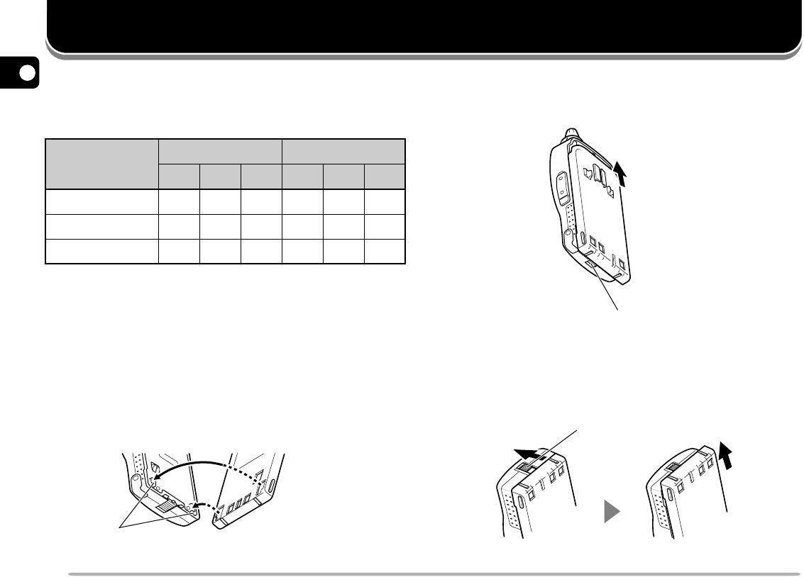
2Slide the battery pack along the back of the
transceiver until the release latch on the base of the
transceiver locks the battery pack in place.
3To remove the battery pack, push up the release
latch, then slide the battery pack back.
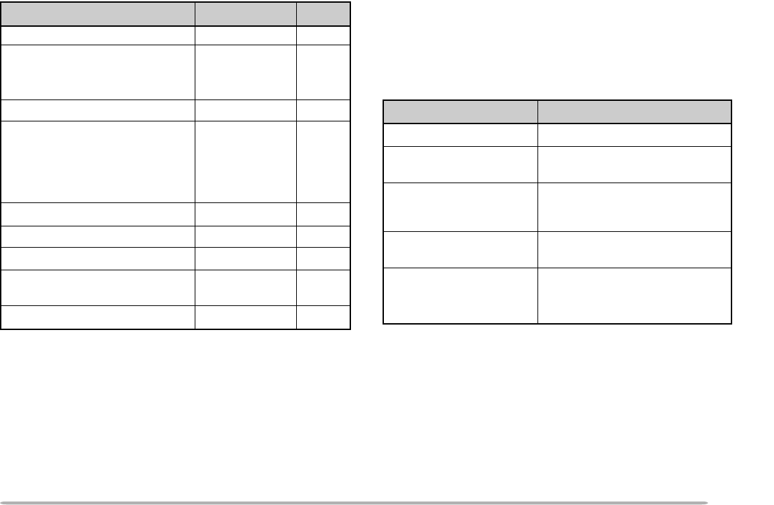
BATTERY OPERATING TIME
The following table shows the approximate battery life
(hours) relative to the transmit output power.
PB-38 NiCd
Batteries
UHF Band
VHF Band
Alkaline
PB-39 NiCd
HI LO EL HI LO EL
4.5
3.5
14
10
8
28
13
14
40
4.5
3.2
14
8
7.2
27
12
14
30
INSTALLING THE NiCd BATTERY PACK
Note:
Because the battery pack is provided uncharged, charge the
battery pack before using it with the transceiver. For the method of
charging the battery pack, refer to “CHARGING THE NiCd BATTERY
PACK” {page 43}.
1Position the two grooves on the inside bottom corners
of the battery pack over the corresponding guides on
the back of the transceiver.
Guide
Release latch
Release latch
3
1
2
3
4
5
6
7
8
9
10
11
12
13
14
15
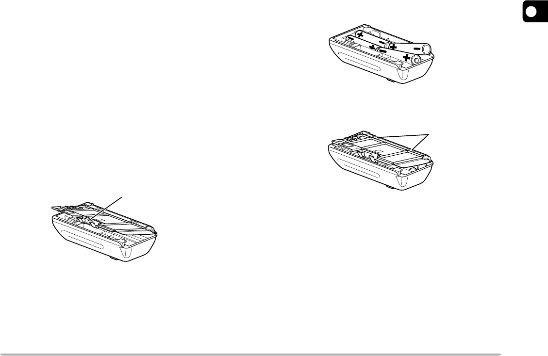
INSTALLING ALKALINE BATTERIES
WARNING!
◆
DO NOT INSTALL THE BATTERIES IN A HAZARDOUS
ENVIRONMENT WHERE SPARKS COULD CAUSE AN
EXPLOSION.
◆
NEVER DISCARD OLD BATTERIES IN FIRE BECAUSE
EXTREMELY HIGH TEMPERATURES CAN CAUSE BATTERIES
TO EXPLODE.
Note:
◆
It is recommended to use high quality alkaline batteries rather than
manganese batteries to enjoy longer periods of battery life. Do not
use commercially available NiCd batteries.
◆
If you will not use the transceiver for a long period, remove the
batteries from the battery case.
◆
Do not use different quality of batteries together.
◆
When the battery voltage is low, replace all four old batteries with
new ones.
1To open the battery case cover, push on the locking
tab, then pull the cover.
2Insert (or remove) four AA (LR6) alkaline batteries.
•Be sure to match the battery polarities with those
marked on the bottom of the battery case.
3Align the two tabs on the battery case cover, then
close the cover until the locking tab clicks.
4To install the battery case onto (or remove from) the
transceiver, follow steps 1 to 3 for INSTALLING THE
NiCd BATTERY PACK {page 2}.
Tab
Locking tab
1
2
3
4
5
6
7
8
9
10
11
12
13
14
15
4
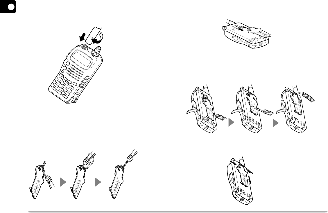
INSTALLING THE ANTENNA
Hold the provided antenna at its base, and screw the
antenna into the connector on the top panel of the
transceiver until it is snug.
ATTACHING THE HAND STRAP
If you want, attach the provided hand strap to the belt
hook before installing the hook onto the transceiver.
INSTALLING THE BELT HOOK
Install the provided belt hook onto the back of the battery
pack or the battery case.
•To lock the cable of an optional speaker microphone, first
position the cable over the left groove on the transceiver.
Then install the belt hook. Last position the cable over the
right groove.
To remove the belt hook, pull the belt hook downward
while pushing its tabs from both sides.
q
w
5
1
2
3
4
5
6
7
8
9
10
11
12
13
14
15
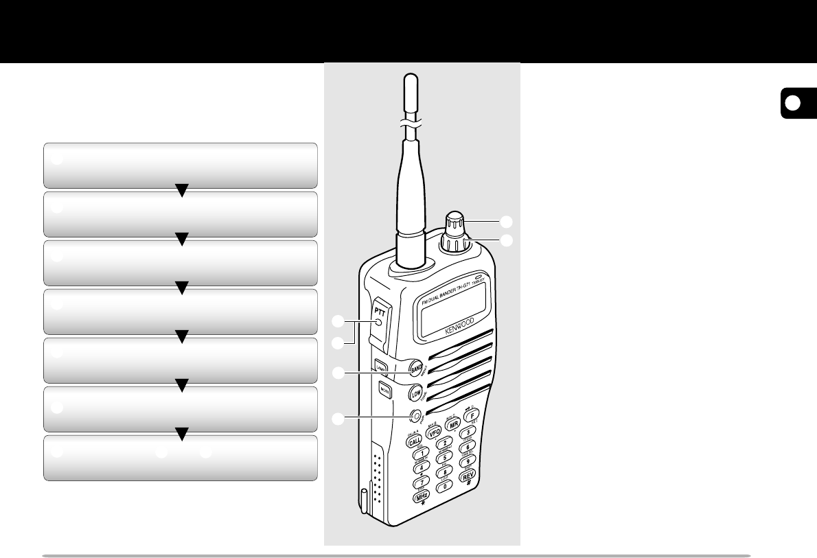
The 7 steps given here will get you on the air
in your first QSO right away. So, you can
enjoy the exhilaration that comes with
opening a brand new transceiver.
Note:
When received signals are too weak to recognize,
press and hold
[MONI]
to hear clearer signals. You will,
however, also hear background noise.
FIRST QSO
CAUTION:
◆
THE RECOMMENDED DUTY CYCLE IS
1 MINUTE OF TRANSMISSION AND
3 MINUTES OF RECEPTION. LONGER
TRANSMISSIONS OR EXTENDED
OPERATION IN THE HIGH POWER MODE
MAY CAUSE THE BACK OF THE
TRANSCEIVER TO GET HOT.
◆
TRANSMITTING WITH THE SUPPLIED
ANTENNA NEAR OTHER ELECTRONIC
EQUIPMENT CAN INTERFERE WITH THAT
EQUIPMENT. ALSO, TRANSMITTING NEAR
A REGULATED POWER SUPPLY, THAT IS
NOT RECOMMENDED BY
KENWOOD
, MAY
CAUSE THE POWER SUPPLY TO OUTPUT
AN EXTREMELY HIGH VOLTAGE. THIS
VOLTAGE COULD DAMAGE BOTH YOUR
TRANSCEIVER AND ANY OTHER
EQUIPMENT CONNECTED TO THE POWER
SUPPLY.
Note:
If input voltage exceeds approximately 18 V,
warning beeps sound and “DC ERR” appears on
the display.
Press the PWR switch for 1 second or
longer.
q
w
e
r
t
y
u
Turn the VOL control clockwise to the
11 o’clock position.
Press [BAND] to select the VHF or
UHF band.
Turn the Tuning control to select a
frequency.
Press and hold the PTT switch, then
speak in a normal tone of voice.
Release the PTT switch to receive.
Repeat steps t and y to continue
communication.
q
w
e
r
t
y
1
2
3
4
5
6
7
8
9
10
11
12
13
14
15
6
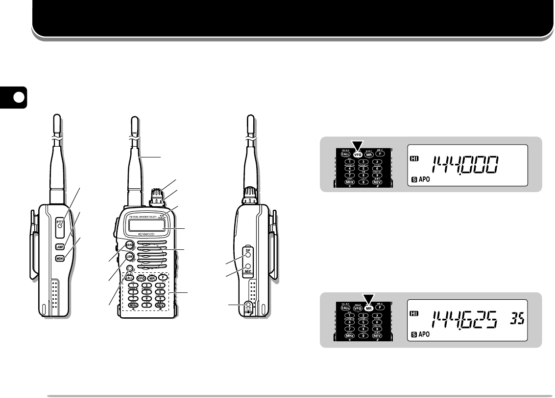
GETTING ACQUAINTED
ORIENTATION BASIC TRANSCEIVER MODES
This section introduces you to the basic modes you can
select on this transceiver.
VFO mode
Press [VFO] to select. In this mode you can change the
operating frequency using the Tuning control.
Memory Recall mode
Press [MR] to select. In this mode you can change
memory channels, using the Tuning control, where you
stored frequencies and related data. You cannot enter
this mode unless you program one memory channel at
least. For further information, refer to “MEMORY
CHANNELS” {page 17}.
Antenna
Tuning control
On Air/Busy
lamp
Display
Speaker/
Microphone
MIC jack
SP jack
Keypad
LOW
key
PWR
switch
PTT
switch
MONI
key
LAMP
key
BAND
key
DC IN
jack
VOL control
7
1
2
3
4
5
6
7
8
9
10
11
12
13
14
15
Menu mode
Press [F], [BAND] to select. In this mode you can
change Menu Nos. using the Tuning control.
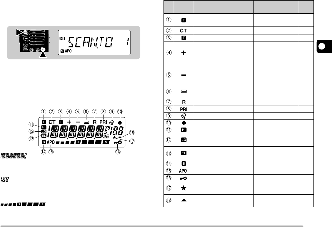
DISPLAY
On the display you will see various indicators that show
what you have selected. Sometimes you may not recall
what those indicators mean or how you can cancel the
current setting. In such a case, you will find the following
table very useful.
Displays various alphanumeric information such as an
operating frequency or menu selection.
Displays the current memory channel when in Memory
Recall mode.
Shows the strength of received signals. While
transmitting, shows the current relative battery charge.
2
1
What You Selected
Indicator What You Press
to Cancel
Ref.
Page
[F]
1
TH-G71E only
Second function select
mode —
CTCSS [F], [6] 32
14
13
13
13
16
Tone function [F], [LOW]
Plus offset direction [F], [REV],
[F], [REV]
(TH-G71E: one
more [F], [REV])
Minus offset direction
(–7.6 MHz)
1
Minus offset direction
[F], [REV]
Reverse function [REV]
[F], [REV]
(TH-G71E: one
more [F], [REV])
Priority Scan [F], [8] 31
Tone Alert [F], [7] 38
AM mode Use Menu No.16 38
High transmit power Default setting 9
Low transmit power [LOW], [LOW]
to restore default 9
Economic low transmit
power 9
Automatic Power Off
Use Menu No. 4
[LOW] to restore
default
37
Battery Saver
Use Menu No. 5 37
Transceiver Lock [F] (1 s) 37
Memory Channel
Lockout [F], [0] 27
Memory channel
containing data —18
1
2
3
4
5
6
7
8
9
10
11
12
13
14
15
8
OPERATING BASICS
SWITCHING POWER ON/OFF
1Press the PWR switch (1 s) to switch ON the
transceiver.
•A beep sounds.
2To switch OFF the transceiver, press the PWR switch
(1 s) again.
ADJUSTING VOLUME
Turn the VOL control clockwise to increase the audio
level and counterclockwise to decrease the audio level.
•If background noise is inaudible because of the Squelch
function, press and hold [MONI], then turn the VOL control.
While pressing [MONI], you will hear background noise.
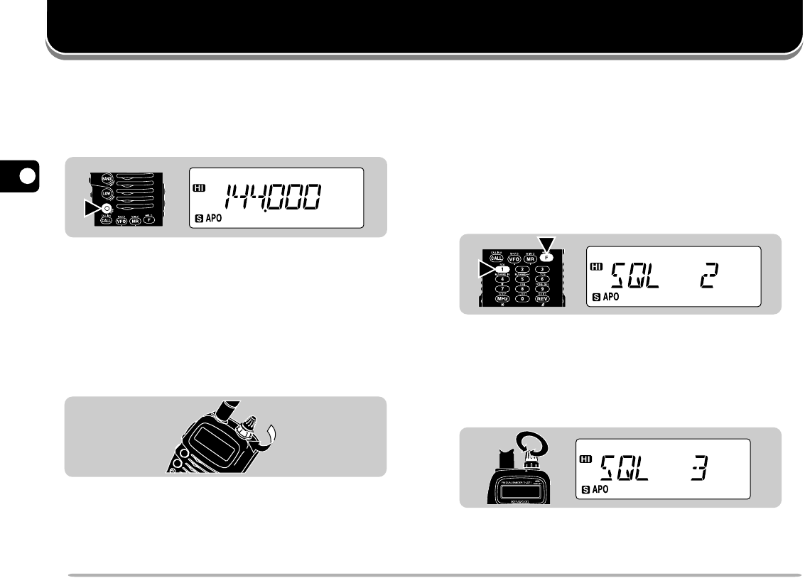
ADJUSTING SQUELCH
The purpose of the Squelch function is to silence
background noise output from the speaker (squelch
closed) when no signals are present. When the squelch
level is set correctly, you will hear sound (squelch
opened) only while a station is actually being received.
1Press [F], [1].
•The current squelch level appears. The default is level
2.
2Turn the Tuning control to select the squelch level in
the range 0 to 5.
•Select just the level at which the background noise is
eliminated when no signal is present.
•The larger the level number you select, the stronger the
signals you need to receive to hear.
3Press any key other than [LAMP] and [MONI] to
complete the setting.
1s
2
1
9
1
2
3
4
5
6
7
8
9
10
11
12
13
14
15
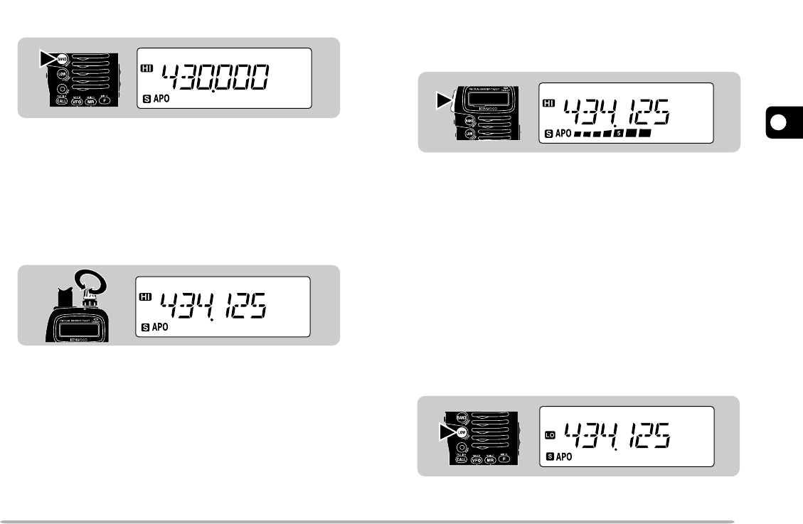
SELECTING A BAND
Press [BAND] to select the VHF or UHF band.
Note:
If in Memory Recall mode {page 6}, press
[VFO]
, then press
[BAND]
to select a band.
SELECTING FREQUENCIES
Turn the Tuning control clockwise to increase the
frequency or counterclockwise to decrease the
frequency.
•To change frequencies in steps of 1 MHz, press [MHz] first.
1 MHz digit blinks. Pressing [MHz] again cancels this
function.
•If you cannot select a particular frequency, the frequency
step size needs to be changed. See “CHANGING
FREQUENCY STEP SIZE” {page 40}.
•You can also select frequencies with the numeric keys. See
“KEYPAD DIRECT ENTRY” {page 40}.
TRANSMITTING
1When ready to begin transmitting, press and hold the
PTT switch and speak in a normal tone of voice.
•The On Air lamp lights red and the battery meter
appears.
•Speaking too close to the microphone, or too loudly,
may increase distortion and reduce intelligibility of your
signal at the receiving station.
•The battery meter shows the current relative battery
charge.
2When you finish speaking, release the PTT switch.
Time-Out Timer:
Holding down the
PTT
switch for more than
10 minutes causes the transceiver to generate a beep and stop
transmitting. Release, then press the
PTT
switch to resume transmitting.
You cannot switch this function OFF.
nSelecting Output Power
Press [LOW] to select high (default), low, or
economic low power (lowest).
•“HI”, “LO”, or “EL” appears to show the current selection.
Note:
Selecting lower transmit power is a wise method to reduce
battery consumption if communication is still reliable.
1
2
3
4
5
6
7
8
9
10
11
12
13
14
15
10
WHAT IS A MENU?
Many functions on this transceiver are selected or
configured via a software-controlled Menu instead of
physical controls on the transceiver. Once familiar with
the Menu system, you will appreciate the versatility it
offers.
MENU ACCESS
1Press [F], [BAND] to enter Menu mode.
•The last Menu No. used appears.
2Turn the Tuning control to select the desired Menu
No.
3Press [BAND] to switch the selection.
•Depending on Menu Nos., press [BAND], then turn the
Tuning control to select numeric values. Press [BAND]
again to complete the setting.
4Press any key other than [BAND], [LAMP], and
[MONI] to exit Menu mode.
MENU SET-UP
2
1

11
1
2
3
4
5
6
7
8
9
10
11
12
13
14
15
MENU CONFIGURATION
Menu
No.
Ref.
Page
Description Selections Default
Scan resume method 25
Time-Operated
1
Memory recall method 19
All bands2
Battery Saver ON/OFF 37
ON4
Automatic Power Off ON/OFF 37
ON5
Beep function ON/OFF 38
ON6
Automatic Repeater Offset ON/OFF 15
ON7
Offset frequency 00.000 MHz to 29.950 MHz 13
See reference page.8
Tuning Control Enable ON/OFF 37
OFF9
DTMF number storing/ confirming See reference page. 35
10
Priority Scan method Mode A/ Mode B 31
Mode A11
TX Inhibit ON/OFF 37
OFF12
DTMF Tone TX Hold 34
OFF13
Speaker configuration
ON/OFF
39
Single speaker
14
Transceiver Control
1
ON/OFF —
OFF15
AM mode/ FM mode 38
AM mode
16
39
3
Time-Operated (TO)/ Carrier-
Operated (CO)/ Seek (SE)
Programmable VFO
(Upper/ lower limits)
Frequencies selectable on the
band
Upper/lower receive
frequency limits on the band
Single speaker (ONE)/
Two speakers (BOTH)
AM/FM selection
2
(U.S.A./Canada only)
All bands (ALL)/
Single band (ONE)
1 This menu item is used for controlling the transceiver using a personal computer. For further information, consult your dealer.
2 This menu item is accessible only after selecting the 118 MHz band.
1
2
3
4
5
6
7
8
9
10
11
12
13
14
15
12
OPERATING THROUGH REPEATERS
Repeaters are often installed and maintained by radio
clubs, sometimes with the cooperation of local
businesses involved in the communications industry.
Compared to simplex communication, you can usually
transmit over much greater distances by using a
repeater. Repeaters are typically located on a mountain
top or other elevated location. Often they operate at
higher ERP (Effective Radiated Power) than a typical
station. This combination of elevation and high ERP
allows communications over considerable distances.
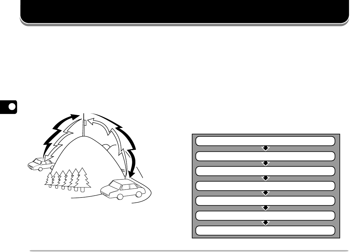
Select a band.
Select a receive frequency.
Select an offset direction.
Select an offset frequency.
Activate the Tone function, if necessary.
Select a tone frequency, if necessary.
Press the PTT switch.
REPEATER ACCESS
Most amateur radio voice repeaters use a separate
receive and transmit frequency. You can set a separate
transmit frequency by selecting the offset frequency and
offset direction with respect to the receive frequency. In
addition, some repeaters may require the transceiver to
transmit a tone before the repeater can be used. To
transmit this required tone, activate the Tone function
and select a tone frequency.
The required offset direction, offset frequency, and tone
frequency depend on the repeater you are accessing.
Consult your local repeater reference.
Flow Chart for Repeater Access
TX: 144.725 MHz
TX tone: 88.5 Hz
RX: 145.325 MHz
TX: 144.725 MHz
TX tone: 88.5 Hz
RX: 145.325 MHz
13
1
2
3
4
5
6
7
8
9
10
11
12
13
14
15
■Selecting Offset Direction
Select whether the transmit frequency will be higher
(+) or lower (–) than the receive frequency.
1Select the desired band.
2Press [F], [REV].
•Each time you repeat this key operation, the offset
direction changes as shown below.
If the offset transmit frequency falls outside the
allowable transmit frequency range, transmitting is
inhibited until the transmit frequency is brought within
the band limits by one of the following methods:
•Move the receive frequency further inside the band.
•Change the offset direction.
Note:
While using an odd-split memory channel or transmitting, you
cannot change the offset direction.
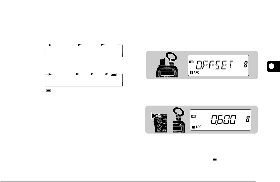
■Selecting Offset Frequency
Select how much the transmit frequency will be offset
from the receive frequency. The default offset
frequency on the VHF band is 600 kHz no matter
which market version; the default on the UHF band is
5 MHz (TH-G71A) or 1.6 MHz (TH-G71E).
1Select the desired band.
2Press [F], [BAND] to enter Menu mode.
3Select Menu No. 8 (OFFSET).
4Press [BAND], then select the appropriate offset
frequency.
•The selectable range is from 00.000 MHz to
29.950 MHz in steps of 50 kHz.
5Press [BAND] again to complete the setting.
6Press any key other than [BAND], [LAMP], and
[MONI] to exit Menu mode.
TH-G71E only:
If you have selected “
” for the offset direction, you
cannot change the default (–7.6 MHz).
Note:
After changing the offset frequency, the new offset frequency
will also be used by Automatic Repeater Offset.
Simplex
+–
Simplex
+–
: Pro
g
rams –7.6 MHz offset.
TH-G71A/E
(VHF)
TH-G71A
(UHF)
TH-G71E
(UHF)
12
1
2
3
4
5
6
7
8
9
10
11
12
13
14
15
14
■Activating Tone Function
1Select the desired band.
2Press [F], [LOW] to switch the Tone function ON
(or OFF).
•“T” appears when the Tone function is ON.
Note:
You cannot use the Tone and CTCSS functions
simultaneously. Switching the Tone function ON after activating the
CTCSS deactivates the CTCSS.
TH-G71E only:
When you access repeaters that require 1750 Hz
tones, you need not activate the Tone function. No matter which
selection you make here, pressing
[LOW]
while pressing the
PTT
switch or simply pressing
[LOW]
causes the transceiver to transmit
1750 Hz tones.
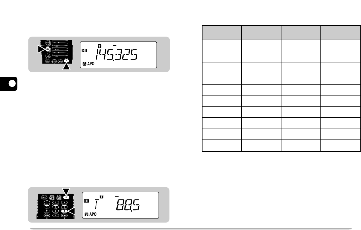
■Selecting a Tone Frequency
1Select the desired band.
2 Press [F], [LOW] to activate the Tone function.
•“T” appears.
3Press [F], [9].
•The current tone frequency appears and blinks.
4Turn the Tuning control to select a tone
frequency.
5Press any key other than [LAMP] and [MONI] to
complete the setting.
67.0
71.9
74.4
77.0
79.7
82.5
85.4
88.5
91.5
94.8
97.4
100.0
103.5
107.2
110.9
114.8
118.8
123.0
127.3
131.8
136.5
141.3
146.2
151.4
156.7
162.2
167.9
173.8
179.9
186.2
192.8
203.5
210.7
218.1
225.7
233.6
241.8
250.3
Freq. (Hz) Freq. (Hz) Freq. (Hz) Freq. (Hz)
TH-G71E only:
To transmit 1750 Hz tones, press and hold the
PTT
switch, then press
[LOW],
or simply press and hold
[LOW].
Releasing
[LOW]
quits transmitting 1750 Hz tones.
2
1
2
1
15
1
2
3
4
5
6
7
8
9
10
11
12
13
14
15
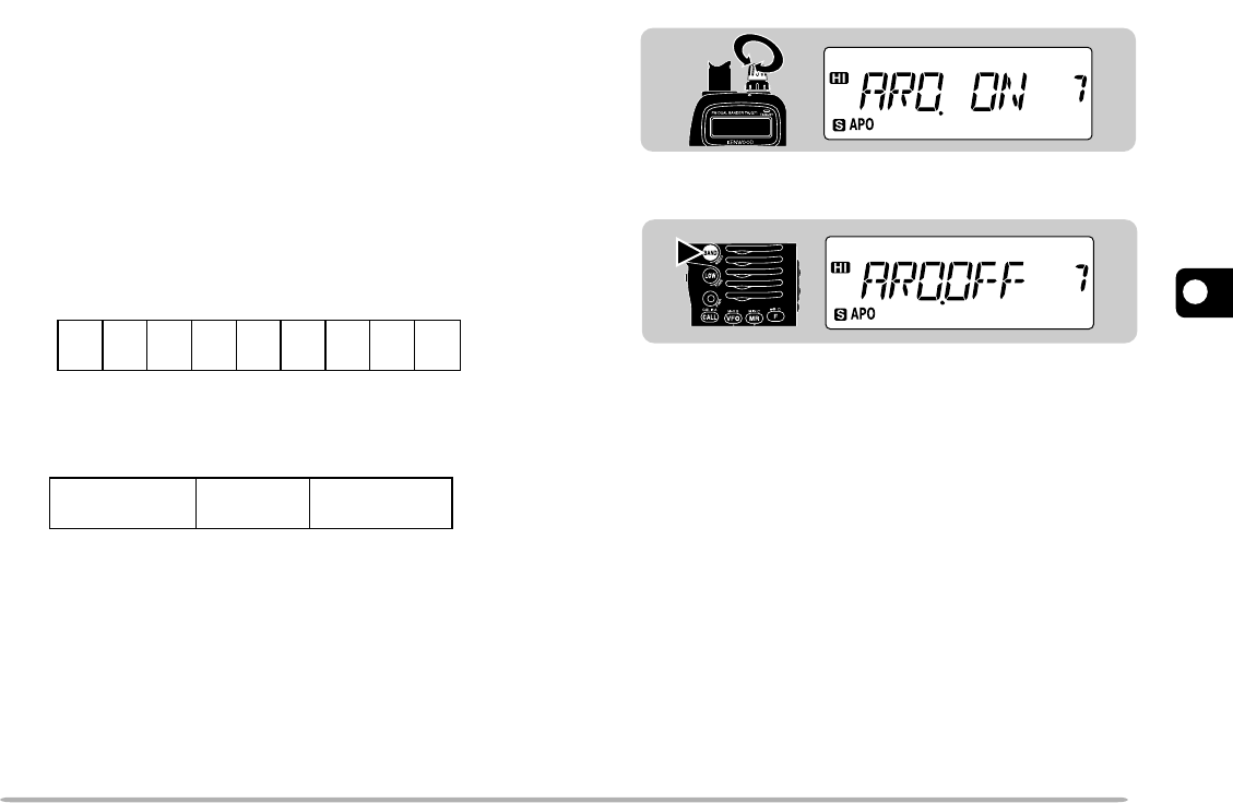
■Automatic Repeater Offset
(U.S.A./ Canada/ Europe Only)
This function automatically selects an offset direction
and activates the Tone function, according to the
frequency that you select on the VHF band. The
transceiver is programmed for offset direction as
shown below. To obtain an up-to-date band plan for
repeater offset direction, contact your national
Amateur Radio association.
U.S.A. and Canada versions
This complies with the standard ARRL band plan.
European versions
Note:
Automatic Repeater Offset does not function when Reverse is
ON. However, pressing
[REV]
after Automatic Repeater Offset has
selected an offset (split) status, exchanges the receive and transmit
frequencies.
1Press [F], [BAND] to enter Menu mode.
2Select Menu No. 7 (ARO).
3Press [BAND] to switch the function ON (default)
or OFF.
4Press any key other than [BAND], [LAMP], and
[MONI] to exit Menu mode.
+−
−− +S
S
SS
144.0 145.5 146.4 147.0 147.6
145.1 146.0 146.6 147.4 148.0 MHz
S: Sim
p
lex
S
S
S: Sim
p
lex
–
144.0 145.6 145.8 146.0 MHz
1
2
3
4
5
6
7
8
9
10
11
12
13
14
15
16
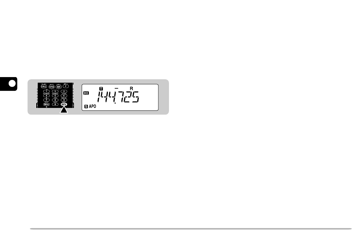
REVERSE FUNCTION
When used while monitoring a repeater, the Reverse
function allows you to manually check the signal strength
of a station accessing the repeater. If the station’s signal
is strong, it is best to move to a simplex frequency to
continue the contact and free up the repeater.
Press [REV] to switch the Reverse function ON (or
OFF).
•The receive frequency and the transmit frequency are
exchanged.
• “R” appears when the function is ON.
Note:
◆
If pressing
[REV]
places the transmit frequency outside the allowable
transmit frequency range, an error beep sounds when
[PTT]
is
pressed, and transmission is inhibited.
◆
If reversal would place the receive frequency outside the receive
frequency range, an error beep sounds when
[REV]
is pressed. No
reversal occurs.
◆
Automatic Repeater Offset does not function while Reverse is ON.
◆
You cannot switch Reverse ON or OFF while transmitting.
17
1
2
3
4
5
6
7
8
9
10
11
12
13
14
15
MEMORY CHANNELS
In memory channels, you can store frequencies and
related data that you often use. Then you need not
reprogram those data every time. You can quickly recall
wanted channels by simple operation. A total of 200
memory channels are available for VHF and UHF.
You can also store a name for each memory channel.
For more information, see “NAMING MEMORY
CHANNELS” {page 20}.
SIMPLEX&REPEATER OR ODD-SPLIT MEMORY
CHANNEL?
You can use each memory channel as a simplex&
repeater channel or odd-split channel. Store only one
frequency to use as a simplex&repeater channel or two
separate frequencies to use as an odd-split channel.
Select either application depending on the operations
you have in mind.
Simplex&repeater channel allows:
•Simplex frequency operation
•Repeater operation with a standard offset
(If an offset direction and offset frequency are stored)
Odd-split channel allows:
•Repeater operation with a non-standard offset
Note:
Not only can you store data in memory channels, but you can also
overwrite existing data with new data.
The data listed below can be stored in each memory
channel:
Yes
Yes
Yes
Yes
Yes
Yes
Yes
Yes
Yes
Yes
Yes
Yes
Yes
Yes
Yes
Yes
Yes
N/A
N/A
N/A
Yes
Yes
Yes
Parameter Simplex&
Repeater Odd-split
Receive frequency
Transmit frequency
Tone frequency
Tone ON/OFF
CTCSS frequency
CTCSS ON/OFF
Frequency step size
Offset direction
Offset frequency
Reverse ON/OFF
Memory channel lockout
Memory channel name
AM/FM mode selection
(U.S.A./Canada only) Yes Yes
Yes: Can be stored in memory.
N/A: Not applicable
1
2
3
4
5
6
7
8
9
10
11
12
13
14
15
18
7Press [MR].
•The selected frequency and related data are stored in
the memory channel.
•If the memory channel selected in the previous step
already contained data, the new data overwrites the
previous data.
STORING ODD-SPLIT REPEATER FREQUENCIES
Some repeaters use a receive and transmit frequency
pair with a non-standard offset. To access those
repeaters, it is necessary to store two separate
frequencies in a single memory channel. The following
steps will allow you to operate on those repeaters
without having to alter the offset programming in the
Menu.
1Store the appropriate receive frequency by using
steps 1 to 7 given for simplex or standard repeater
frequencies.
•If necessary, select Tone ON {page 14} and tone
frequency {page 14}.
2Select the appropriate transmit frequency.
3Press [F].
4Within 10 seconds, turn the Tuning control to select
the same memory channel that you selected in step 1
above.
5Press [PTT]+[MR].
•The selected transmit frequency is stored in the memory
channel.
Note:
◆
When you recall an odd-split memory channel, “+” and “–” appear on
the display. To confirm the transmit frequency, press
[REV]
.
◆
Transmit Offset status and Reverse status are not stored in an odd-
split memory channel.
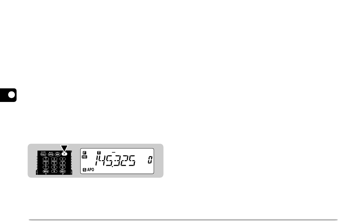
STORING SIMPLEX FREQUENCIES OR STANDARD
REPEATER FREQUENCIES
1Press [VFO] to select VFO mode.
2Press [BAND] to select the desired band.
3Turn the Tuning control to select the desired
frequency.
•You can also enter digits directly from the keypad. See
“KEYPAD DIRECT ENTRY” {page 40}.
4If storing a standard repeater frequency, select the
following data:
Offset direction {page 13}
Tone ON, if necessary {page 14}
Tone frequency, if necessary {page 14}
•If storing a simplex frequency, you may select other
related data (CTCSS ON, CTCSS freq., etc.)
5Press [F].
•A memory channel number appears on the right and
blinks.
•A triangle icon appears below the memory channel
number if the channel already contains data.
6Within 10 seconds, turn the Tuning control to select
the desired memory channel.
19
1
2
3
4
5
6
7
8
9
10
11
12
13
14
15
RECALLING MEMORY CHANNELS
1Press [MR] to enter Memory Recall mode.
•The memory channel used last is recalled.
2Turn the Tuning control to select the desired memory
channel.
•You cannot recall empty memory channels.
•To restore VFO mode, press [VFO].
You may want to recall only memory channels that store
frequencies of the current band. Access Menu No. 2
(MR) to select “ONE”. The default is “ALL”.
ONE: Recalls only memory channels of the current
band.
ALL: Recalls all programmed memory channels. For
example, allows you to recall a VHF frequency
channel when operating the UHF band.
Note:
◆
You can also recall memory channels by directly entering numeric
keys. See “Memory Channel Number Entry” {page 40}.
◆
When you recall an odd-split memory channel, “+” and “–” appear on
the display. Press
[REV]
to display the transmit frequency.
◆
After recalling a memory channel, you may program data such as
Tone or CTCSS. These settings, however, are cleared once you
select another channel or the VFO mode. To permanently store the
data, overwrite the channel contents {page 18}.
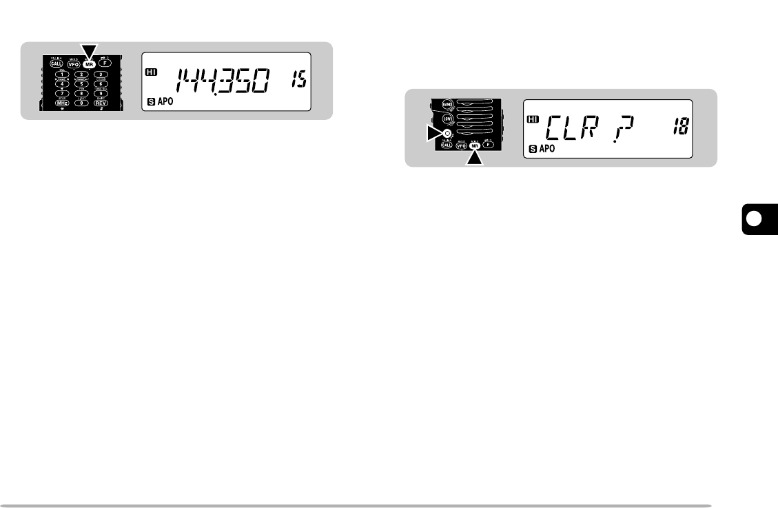
CLEARING MEMORY CHANNELS
1Recall the desired memory channel.
2Switch OFF the power to the transceiver.
3Press [MR]+ POWER ON.
•A confirmation message appears.
4Press [MR] again.
•The contents of the selected memory channel are
erased.
2
1
1
2
3
4
5
6
7
8
9
10
11
12
13
14
15
20
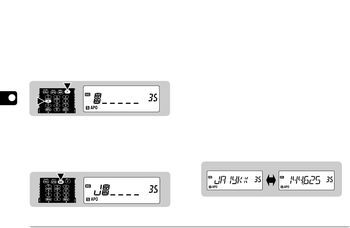
NAMING MEMORY CHANNELS
You can name memory channels using up to 6
alphanumeric characters. When you recall a named
memory channel, its name appears on the display
instead of the stored frequency. Names can be
callsigns, repeater names, cities, names of people, etc.
Note:
You can also name the Program Scan and Priority channels , but
you cannot name the Call channel.
1Recall the desired memory channel.
2Press [F], [4] to enter Memory Naming mode.
•The first digit blinks.
•If you recall a memory channel that has a name stored,
the last digit blinks.
3Turn the Tuning control to select the first digit.
•You can select “0” to “9”, “A” to “Z”, “–”, “/ ”, or a space.
4Press [MR].
•The second digit blinks.
5Repeat steps 3 and 4 to enter up to 6 digits.
•After selecting the 6th digit, you need not press [MR].
•To erase and re-enter the preceding digits, press [VFO]
as many times as required.
6Press [F] to complete the setting.
Note:
◆
Names can be assigned only to memory channels in which you have
stored frequencies and related data.
◆
The stored names can be overwritten by repeating steps 1 to 6.
◆
The stored names can be erased by repeatedly pressing
[VFO]
in
step 2 then pressing
[F].
◆
The stored names also are erased by clearing memory channels.
SWITCHING MEMORY NAME/ FREQUENCY DISPLAY
After storing memory names, you can switch the display
between memory names and frequencies. You may
sometimes want to confirm frequencies stored in named
memory channels.
1Press [MR] to enter Memory Recall mode.
2Press [F], [5] to switch between memory name and
frequency display.
2
1
21
1
2
3
4
5
6
7
8
9
10
11
12
13
14
15
■Changing Call Channel Contents
1Select the desired band.
2Select the desired frequency and related data
(Tone, CTCSS, etc.) using VFO mode or Memory
Recall {page 19}.
•When you program the Call channel as an odd-split
channel, select a receive frequency.
3Press [F], [CALL].
•The selected frequency and related data are stored
in the Call channel.
•The previous mode is restored.
To also store a transmit frequency, proceed to the
next step.
4Select the desired transmit frequency.
5Press [F].
6Press [PTT]+[CALL].
•The selected transmit frequency is stored in the Call
channel, and the previous mode is restored.
Note:
◆
Transmit Offset status and Reverse status are not stored in an
odd-split Call channel.
◆
Lockout status and memory names are not copied from a
memory channel to the Call channel.
◆
To store data other than frequencies, select the data in step 2,
not step 4.
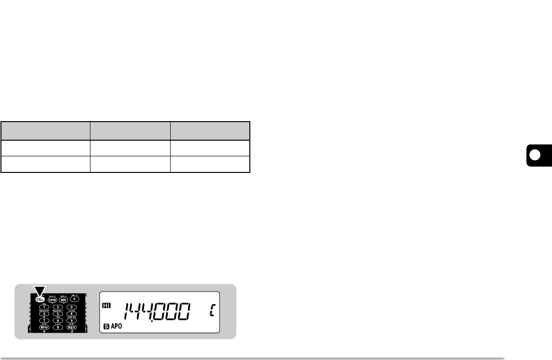
CALL CHANNEL
The Call channel can be used to store any frequency
and related data that you will recall often. The Call
channel also can be programmed either as a
simplex&repeater or odd-split channel. No matter what
mode the transceiver is in, the Call channel can always
be selected quickly. You may want to dedicate the Call
channel as an emergency channel within your group. In
this case, the Call/VFO scan {page 29} will be useful.
The default frequency stored in the Call channel is
shown below:
The contents of the Call channel cannot be deleted;
however, you can overwrite old data with new data as
described in the following section.
■Recalling the Call Channel
1Select the desired band.
2Press [CALL] to recall the Call channel.
•“C” appears.
•To restore the previous mode, press [CALL] again.
VHF
Version UHF
144.000 MHz 430.000 MHz
Europe/ General
U.S.A./ Canada 144.000 MHz 440.000 MHz
1
2
3
4
5
6
7
8
9
10
11
12
13
14
15
22
MEMORY ➡ VFO TRANSFERS
Transferring the contents of a memory channel or the
Call channel to the VFO can be useful if you want to
search for other stations or a clear frequency, near the
selected memory channel or Call channel frequency.
1Recall the desired memory channel or the Call
channel.
2Press [F], [VFO].
•The entire contents of the memory channel or the Call
channel are copied to the VFO. VFO mode is selected
after the transfer is completed.
Note:
◆
A transmit frequency from an odd-split memory channel or odd-split
Call channel is not transferred to the VFO. To transfer a transmit
frequency, press
[REV]
, then press
[F]
,
[VFO]
.
◆
Lockout status and memory names are not copied from a memory
channel to the VFO.
◆
If you recall the Call channel in step 1, simply turning the
Tuning
control also transfers the contents to the VFO. The frequency,
however, is changed by one step.
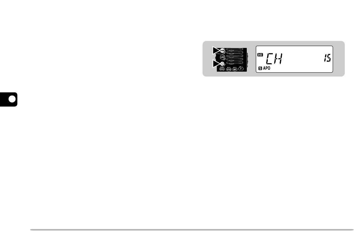
CHANNEL DISPLAY FUNCTION
When this function is switched ON, the transceiver
displays only a memory channel number instead of a
frequency.
Press [BAND]+ POWER ON to switch this function ON
(or OFF).
When in Channel Display mode, you cannot use the
following functions:
•Band Select •VFO Select
•Call Channel Recall •Memory Channel Store
•Memory Name Store •Memory Channel Clear
•Memory ➡ VFO Transfer •Memory Name/ Frequency
Display Switch
•Call Channel Store •Priority Scan
•Call/ Memory Scan •Partial/ Full Reset
Note:
◆
You cannot switch this function ON if you have stored frequencies in
no memory channels.
◆
When in Channel Display mode, you may want to recall only memory
channels of the desired band. Before pressing
[BAND]+ POWER
ON
, select “ONE” in Menu No. 2 (MR), then select the desired band.
2
1
23
1
2
3
4
5
6
7
8
9
10
11
12
13
14
15
INITIALIZING MEMORY
If your transceiver seems to be malfunctioning,
initializing the transceiver may resolve the problem.
Remember that you need to re-program memory
channels after initialization. On the other hand,
initialization is a quick way to clear all memory channels.
Note:
While using the Channel Display or Transceiver Lock function,
you cannot do Partial Reset nor Full Reset.
VHF Band Defaults
UHF Band Defaults
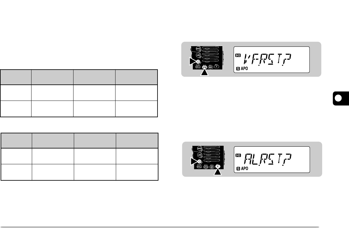
■Partial Reset (VFO)
Use to initialize all settings except the memory
channels, the Call channel, the DTMF channels, and
Memory Channel Lockout.
1Press [VFO]+ POWER ON.
•A confirmation message appears.
•To quit resetting, press any key other than [VFO].
2Press [VFO] again.
■Full Reset (Memory)
Use to initialize all settings.
1Press [F]+ POWER ON.
•A confirmation message appears.
•To quit resetting, press any key other than [F].
2Press [F] again.
2
1
2
1
VFO
Frequency
Version Tone
Frequency
Frequency
Step
U.S.A./
Canada
144.000
MHz 5 kHz 88.5 Hz
Europe/
General
144.000
MHz 12.5 kHz 88.5 Hz
VFO
Frequency
Version Tone
Frequency
Frequency
Step
U.S.A./
Canada
440.000
MHz 25 kHz 88.5 Hz
Europe/
General
430.000
MHz 25 kHz 88.5 Hz
1
2
3
4
5
6
7
8
9
10
11
12
13
14
15
24
SCAN
Scan is a useful feature for hands-off monitoring of your
favorite frequencies. After becoming comfortable with
how to use all types of Scan, the monitoring flexibility
gained will increase your operating efficiency.
Note:
◆
Remember to adjust the squelch threshold level before using Scan.
◆
You cannot start Scan while Tone Alert is ON.
◆
While using CTCSS, Scan stops for any signal received; however,
the squelch opens only for signals that contain the same CTCSS
tone that is selected on your transceiver.
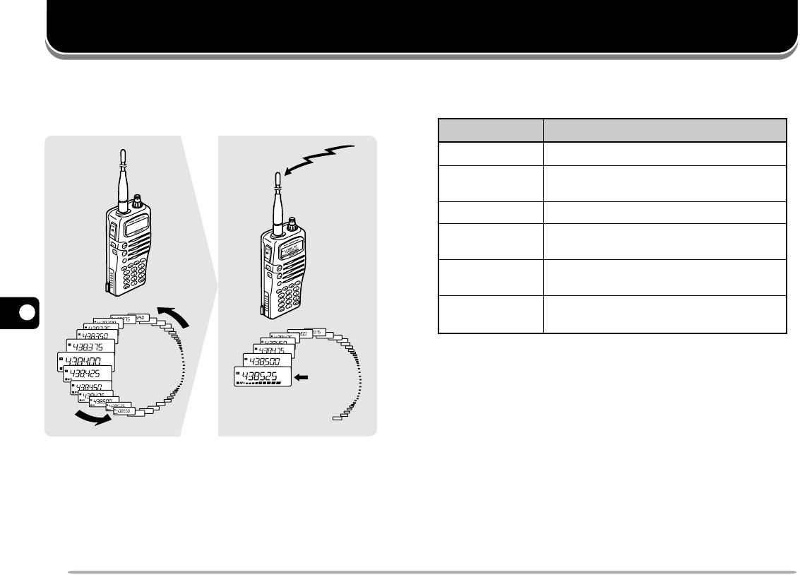
This transceiver provides the following conventional
scans in addition to “Priority Scan” {page 30} that may
be new to you:
VFO Scan All frequencies tunable on the band
MHz Scan All frequencies within 1 MHz range
Scan Type Scan Range
Frequencies stored in the memory
channels
Memory Scan
All frequencies in the range
selected on the band
Program Scan
Call channel plus the current VFO
frequency
Call/VFO Scan
Call channel plus the memory
channel last used
Call/Memory
Scan
438.525 MHz
Stop

25
1
2
3
4
5
6
7
8
9
10
11
12
13
14
15
SCAN RESUME METHODS
Before using Scans other than Priority Scan, it’s
necessary to decide under what condition you want your
transceiver to continue scanning after detecting and
stopping for a signal. You can choose one of the
following modes. The default is Time-Operated mode.
•Time-Operated mode
Your transceiver stops scanning when detecting a signal,
remains there for approximately 5 seconds, and then
continues to scan even if the signal is still present.
•Carrier-Operated mode
Your transceiver stops scanning when detecting a signal
and remains on the same frequency until the signal drops
out. There is a 2 second delay between signal drop-out and
scan resumption to allow time for any responding stations to
begin transmitting.
•Seek mode
Your transceiver stops scanning when detecting a signal
and remains on the same frequency; the transceiver stays
on this frequency even after the signal drops out and does
not automatically resume scanning.
Note:
Pressing and holding
[MONI]
causes the transceiver to stop
scanning; releasing
[MONI]
causes it to resume scanning.
■Selecting Scan Resume Method
1Press [F], [BAND] to enter Menu mode.
2Select Menu No. 1 (SCAN).
3Press [BAND] to select Time-Operated (TO),
Carrier-Operated (CO), or Seek (SE) mode.
4Press any key other than [BAND], [LAMP], and
[MONI] to exit Menu mode.
1
2
3
4
5
6
7
8
9
10
11
12
13
14
15
26
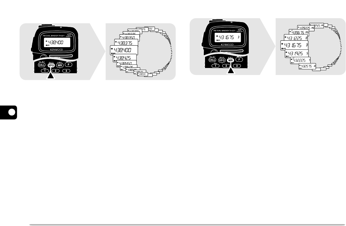
VFO SCAN
VFO Scan allows you to scan all frequencies from the
lowest frequency to the highest frequency on the band.
The current frequency step size {page 40} is used.
1Select the desired band.
2Press [VFO] (1 s).
•The 1 MHz decimal blinks while scanning is in progress.
•Scan starts at the frequency currently displayed.
•To reverse the scan direction, turn the Tuning control
clockwise (upward scan) or counterclockwise (downward
scan).
3To quit VFO Scan, press any key other than [LAMP],
[MONI], and [F].
Note:
The squelch must be closed for Scan to function.
MEMORY SCAN
Memory Scan allows all memory channels containing
data to be scanned.
1Press [MR] (1 s).
•The 1 MHz decimal blinks while scanning is in progress.
•Scan starts with the channel last recalled.
•To reverse the scan direction, turn the Tuning control
clockwise (upward scan) or counterclockwise
(downward scan).
2To quit Memory Scan, press any key other than
[LAMP], [MONI], and [F].
Note:
◆
At least 2 or more memory channels must contain data and must not
be locked out.
◆
The squelch must be closed for Scan to function.
◆
The L0 to L9 and U0 to U9 memory channels and the priority channel
are not scanned.
◆
You can also start Memory Scan when in Channel Display mode.
While Scan is being interrupted, the channel number blinks.
◆
If you select “ONE” using Menu No. 2 (MR), memory channels on
only the current band will be scanned; otherwise, memory channels
on both VHF and UHF bands will be scanned.
27
1
2
3
4
5
6
7
8
9
10
11
12
13
14
15
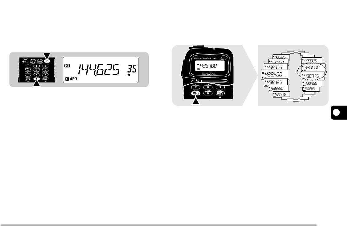
MHz SCAN
MHz Scan allows you to scan a 1 MHz segment of the
band. The current 1 MHz digit determines the limits of
the scan. For example, if the current frequency is
438.400 MHz, then MHz Scan would scan from
438.000 MHz to 438.975 MHz. The exact upper limit
depends on the step size selected.
1Press [VFO] to select VFO mode.
2Select the desired band.
3Press [MHz] (1 s) to start MHz Scan.
•The 1 MHz decimal blinks while scanning is in progress.
•Scan starts at the frequency currently displayed.
•To reverse the scan direction, turn the Tuning control
clockwise (upward scan) or counterclockwise
(downward scan).
4To quit MHz Scan, press any key other than [LAMP],
[MONI], and [F].
■Locking Out Memory Channels
Memory channels that you prefer not to monitor while
scanning can be locked out.
1Recall the desired memory channel.
2Press [F], [0] to switch Lockout ON (or OFF).
•A star appears below the memory channel number
to indicate that the channel has been locked out.
Note:
The L0 to L9 and U0 to U9 memory channels and the priority
channel cannot be locked out.
1
2
1
2
3
4
5
6
7
8
9
10
11
12
13
14
15
28
PROGRAM SCAN
Program Scan is similar to VFO Scan except that you
select the frequency range of the scan.
■Setting Scan Limits
You can store up to 10 scan ranges in memory
channels L0/U0 to L9/U9.
1Select the desired band.
2Turn the Tuning control to display the desired
lower limit.
3Press [F].
4Turn the Tuning control to select a channel in the
range L0 to L9.
5Press [MR].
•The lower limit is stored in the channel.
6Turn the Tuning control to display the desired
upper limit.
7Press [F].
8Turn the Tuning control to select a matching
channel in the range U0 to U9.
•If you have selected for example L3 in step 4,
select U3.
9Press [MR].
•The upper limit is stored in the channel.
10 To confirm the stored scan limits, press [MR], then
select the L and U channels.
Note:
◆
The lower limit must be lower in frequency than the upper limit.
◆
The lower and upper frequency steps must be equal.
◆
The lower and upper limits must be selected on the same band.

29
1
2
3
4
5
6
7
8
9
10
11
12
13
14
15
■Using Program Scan
1Press [VFO] to select VFO mode.
2Select the desired band.
3Select a frequency equal to or between the
programmed scan limits.
4Press [VFO] (1 s).
•The 1 MHz decimal blinks while scanning is in
progress.
•Scan starts at the frequency currently displayed.
•To reverse the scan direction, turn the Tuning
control clockwise (upward scan) or counterclockwise
(downward scan).
5To quit Program Scan, press any key other than
[LAMP], [MONI], and [F].
Note:
◆
The squelch must be closed for Scan to function.
◆
If the frequency step of the current VFO frequency differs from
that of the programmed frequencies, you cannot use Program
Scan.
◆
If the frequency steps of the lower limit and upper limit differ, you
cannot use Program Scan.
◆
If the current VFO frequency is within more than one
programmed scan range, the range stored in the smallest
channel numbers is used.
CALL/VFO SCAN
Use Call/VFO Scan to monitor both the Call channel and
the current VFO frequency on the selected band.
1Press [VFO] to select VFO mode.
2Select the desired band.
3Select the desired frequency.
4Press [CALL] (1 s) to start Call/VFO Scan.
•The 1 MHz decimal blinks while scanning is in progress.
5To quit Call/VFO Scan, press any key other than
[LAMP], [MONI], and [F].
CALL/MEMORY SCAN
Use Call/Memory Scan to monitor both the Call channel
and the desired memory channel.
1Recall the desired memory channel.
2Press [CALL] (1 s) to start Call/Memory Scan.
•The 1 MHz decimal blinks while scanning is in progress.
•The Call channel on the same band as of the selected
memory channel is used for Scan.
3To quit Call/Memory Scan, press any key other than
[LAMP], [MONI], and [F].
Note:
The memory channel last used is scanned even if it has been
locked out.
1
2
3
4
5
6
7
8
9
10
11
12
13
14
15
30
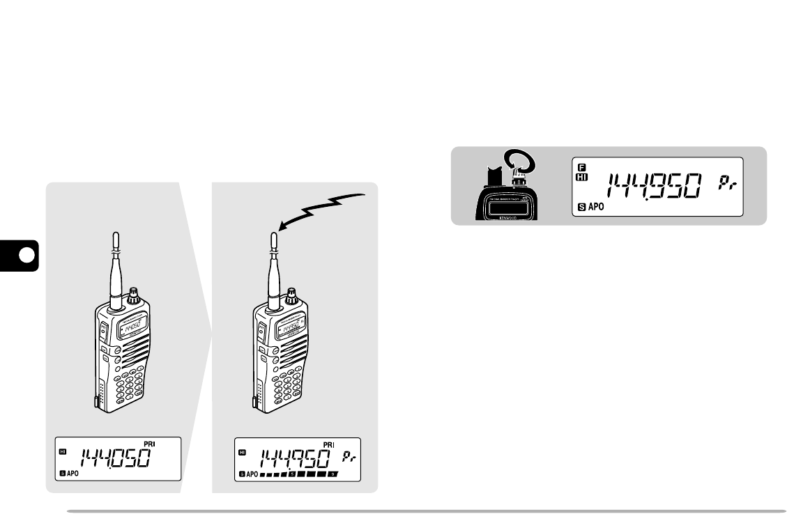
PRIORITY SCAN
You may sometimes want to monitor your favorite
frequency on one band while operating on another band.
Use Priority Scan. This Scan always monitors your
favorite frequency in the background. When receiving
signals on your specific frequency, the transceiver
immediately recalls that frequency on the display and
allows you to use it for QSO. First store your favorite
frequency in the Priority channel and select one of the
two Priority Scan methods.
Note:
If you do not operate any control or key for 3 seconds after signals
drop, the transceiver resumes Priority Scan.
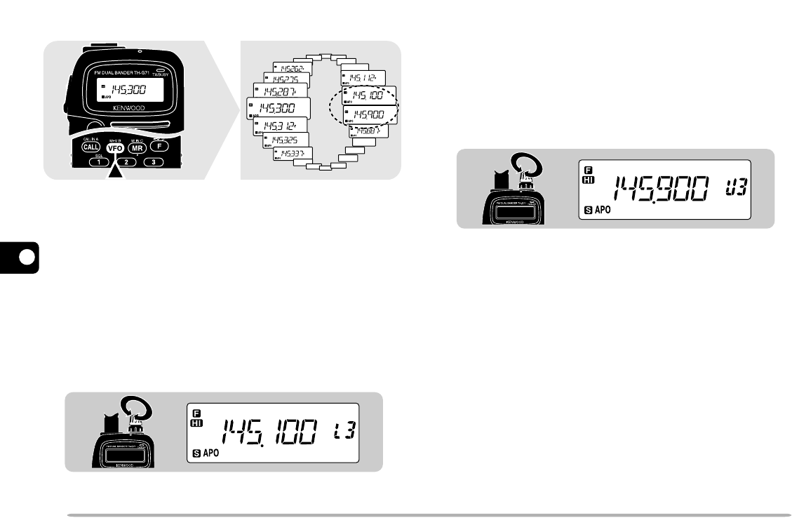
■Storing Frequency in Priority Channel
1Select the desired band.
2Select the desired frequency.
3Press [F].
•A memory channel number appears and blinks.
4Turn the Tuning control to select the Priority
channel.
•“Pr” appears when you select the Priority channel.
5Press [MR].
Note:
Not only can you store data in the Priority channel, but you
can also overwrite existing data with new data.
144.950 MHz
31
1
2
3
4
5
6
7
8
9
10
11
12
13
14
15
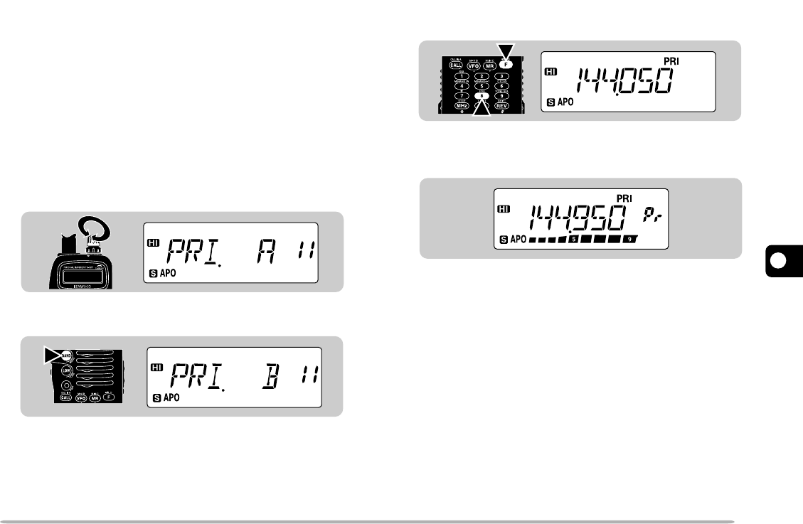
■Selecting Priority Scan Method
This transceiver prepares the following two modes for
Priority Scan. Use mode B when you do not want
Priority Scan to disrupt your current QSO.
Mode A: Monitors the Priority channel every 3 seconds no
matter whether or not signals are being received
on the current operating frequency.
Mode B: Monitors the Priority channel every 3 seconds
only when no signals are present on the current
operating frequency.
1Press [F], [BAND] to enter Menu mode.
2Select Menu No. 11 (PRI).
3Press [BAND] to select mode A (default) or mode
B.
4Press any key other than [BAND], [LAMP], and
[MONI] to exit Menu mode.
■Using Priority Scan
1Press [F], [8] to activate Priority Scan.
•“PRI” appears.
•When signals are received on the Priority channel, a
beep sounds and the Priority channel frequency
appears. In addition, “Pr” appears and blinks.
2Press the PTT switch to transmit on the Priority
channel and release the PTT switch to receive.
•Approximately 3 seconds after signals drop, Priority
Scan resumes.
3To quit Priority Scan, press [F], [8] again.
Note:
◆
When signals are received on the Priority channel programmed
with CTCSS, the Priority channel is recalled; however, the
squelch does not open unless the signals contain the matching
CTCSS tone.
◆
You can simultaneously use Priority Scan and any other type of
Scan; however Priority Scan does not function while the other
scan is being paused.
◆
Pressing and holding
[MONI]
while using Priority Scan allows
you to monitor the current operating frequency; releasing
[MONI]
resumes Priority Scan.
1
2
1
2
3
4
5
6
7
8
9
10
11
12
13
14
15
32
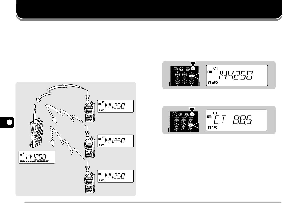
CONTINUOUS TONE CODED SQUELCH SYSTEM (CTCSS)
USING CTCSS
1Select the desired band.
2Press [F], [6] to switch the CTCSS function ON (or
OFF).
•“CT” appears when CTCSS is ON.
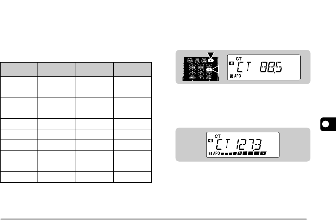
3Press [F], [9].
•The current CTCSS frequency appears and blinks.
4Turn the Tuning control to select a tone frequency.
5Press any key other than [LAMP] and [MONI] to
complete the setting.
6When you are called:
The squelch of your transceiver opens only when the
selected tone is received.
When you make a call:
Press and hold [PTT].
You may sometimes want to hear calls from only specific
persons. The Continuous Tone Coded Squelch System
(CTCSS) allows you to ignore (not hear) unwanted calls
from other persons who are using the same frequency.
Simply select the same CTCSS tone as selected by the
other persons in your group. A CTCSS tone is
subaudible and is selectable from among the 38
standard tone frequencies.
Note:
CTCSS does not cause your conversation to be private. It only
relieves you of listening to unwanted conversations.
2
1
2
1
Received
Not
Received
Not
Received
CTCSS frequency:
82.5 Hz
CTCSS: OFF
CTCSS frequency:
82.5 Hz
CTCSS frequency:
100.0 Hz
33
1
2
3
4
5
6
7
8
9
10
11
12
13
14
15
Note:
◆
Skip steps 3 to 5 if you have already programmed the appropriate
CTCSS frequency.
◆
You can select a separate tone frequency for the CTCSS and Tone
functions.
◆
You cannot use the CTCSS and Tone functions simultaneously.
Switching the CTCSS function ON after activating the Tone function
deactivates the Tone function.
◆
If you select a high tone frequency, receiving audio or noise that
contains the same frequency portions may cause CTCSS to function
incorrectly. To prevent noise from causing this problem, select an
appropriate noise squelch level {page 8}.
■Automatic Tone Frequency ID
This function automatically identifies the incoming
tone frequency on a received signal.
1Select the desired band.
2Press [F], [6] (1 s) to activate the function.
•The current tone frequency appears and the 1 Hz
decimal blinks.
•When a signal is received, the transceiver begins
scanning through all tone frequencies in order to
identify the incoming tone frequency.
•When the tone frequency is identified, the identified
frequency appears and blinks. To continue
scanning, turn the Tuning control.
•The identified frequency is programmed in place of
the currently set CTCSS frequency.
3Press any key other than [LAMP] and [MONI] to
quit the function.
Note:
Received signals are audible while scanning is in progress.
67.0
71.9
74.4
77.0
79.7
82.5
85.4
88.5
91.5
94.8
97.4
100.0
103.5
107.2
110.9
114.8
118.8
123.0
127.3
131.8
136.5
141.3
146.2
151.4
156.7
162.2
167.9
173.8
179.9
186.2
192.8
203.5
210.7
218.1
225.7
233.6
241.8
250.3
Freq. (Hz) Freq. (Hz) Freq. (Hz) Freq. (Hz)
2
1
1
2
3
4
5
6
7
8
9
10
11
12
13
14
15
34
DUAL TONE MULTI-FREQUENCY (DTMF) FUNCTIONS
You can send DTMF tones by using the DTMF keys on
the keypad. The keypad includes the 12 keys found on
a push-button telephone plus 4 additional keys
(A, B, C, D). These additional keys are required for
various control operations by some repeater systems.
MAKING DTMF CALLS
1Press and hold the PTT switch.
2Press the keys in sequence on the keypad to send
DTMF tones.
•The corresponding DTMF tones are transmitted.
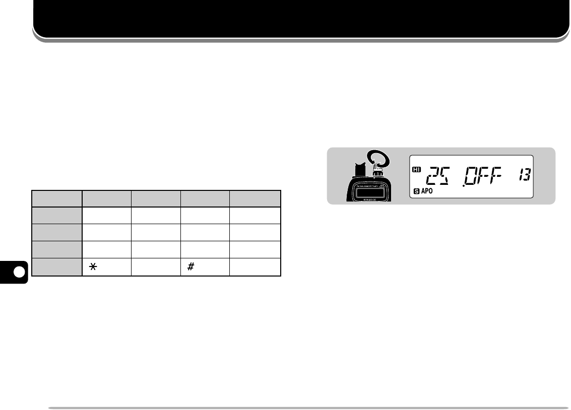
■DTMF Tone TX Hold
This function makes the transceiver remain in the
transmit mode for 2 seconds after you release each
key. So you can release the PTT switch after
beginning to press keys.
1Press [F], [BAND] to enter Menu mode.
2Select Menu No. 13 (2S).
3Press [BAND] to switch the function ON or OFF
(default).
4Press any key other than [BAND], [LAMP], and
[MONI] to exit Menu mode.
■Autopatch (U.S.A. and Canada)
Some repeaters in the U.S.A. and Canada offer a
service called Autopatch. Autopatch allows you to
access the public telephone network by sending
DTMF tones. Some repeaters require a special key
sequence to activate Autopatch. Check with the
repeater control operator.
1336
Freq. (Hz) 1477
1209
1
4
7
1633
697
770
852
941
A (CALL)
B (VFO)
C (MR)
D (F)
2
5
8
0
3
6
9
(MHz) (REV)
35
1
2
3
4
5
6
7
8
9
10
11
12
13
14
15
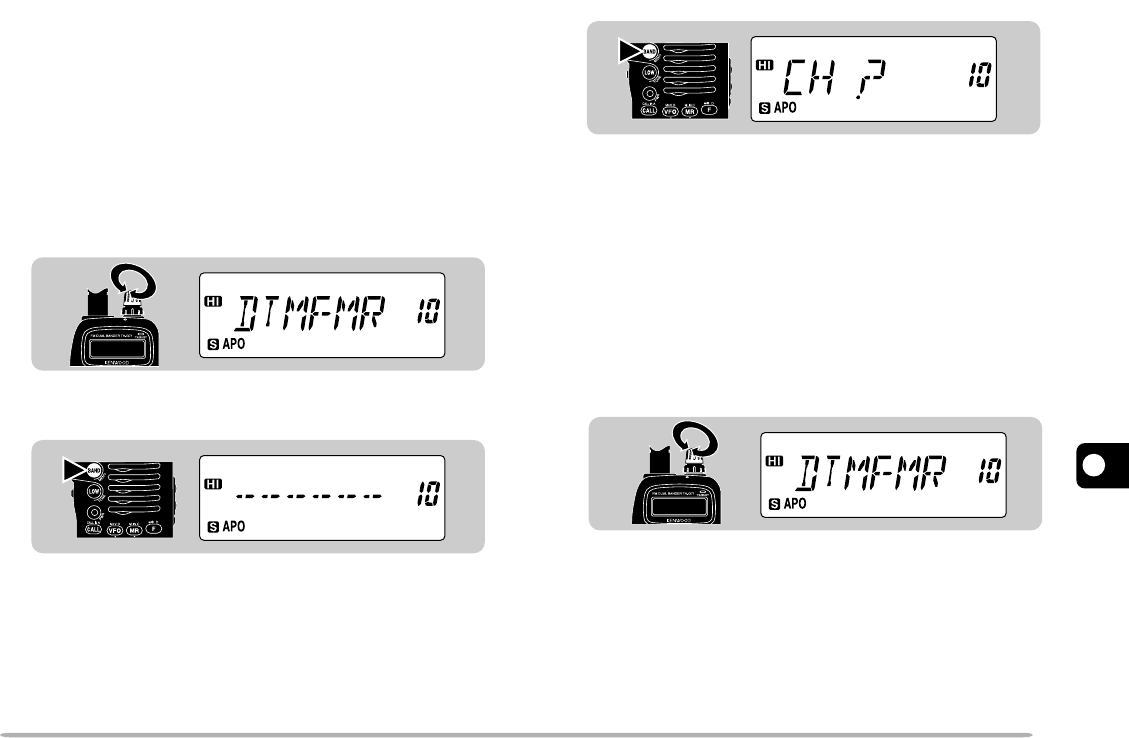
STORING DTMF NUMBERS FOR AUTOMATIC
DIALER
To store a DTMF number with a maximum of 16 digits in
any of 10 dedicated DTMF memory channels, follow the
procedure below.
Note:
Audible DTMF tones from other transceivers near you may be
picked up by your microphone. If so, this could prevent the function from
working correctly.
1Press [F], [BAND] to enter Menu mode.
2Select Menu No. 10 (DTMFMR).
3Press [BAND].
•The display for entering a DTMF number appears.
4Use the keypad to enter the digits of the number to
be stored.
•The corresponding DTMF tones are heard.
•If you enter incorrect digits, press [LOW] to erase all
digits entered.
5Press [BAND] to complete entry.
•The display for entering a channel number appears.
6Press a single key [0] to [9] to select the desired
channel.
•The entered number is stored in the selected channel.
7Press any key other than [BAND], [LAMP], [MONI],
and [0] to [9] to exit Menu mode.
CONFIRMING STORED DTMF NUMBERS
1Press [F], [BAND] to enter Menu mode.
2Select Menu No. 10 (DTMFMR).
3Press a single key [0] to [9] to select the desired
channel.
•The number stored in the channel scrolls across the
display accompanied by DTMF tones from the speaker.
4Press any key other than [BAND], [LAMP], [MONI],
and [0] to [9] to exit Menu mode.
1
2
3
4
5
6
7
8
9
10
11
12
13
14
15
36
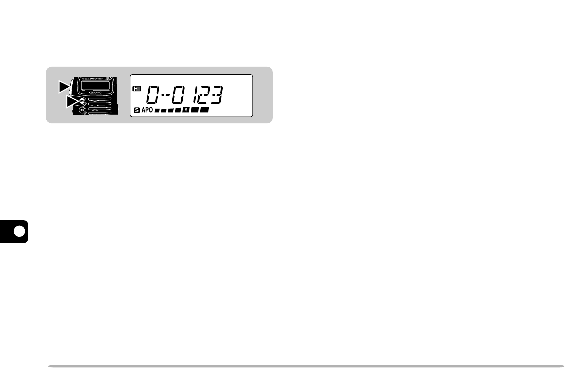
TRANSMITTING STORED DTMF NUMBERS
To transmit a stored DTMF number, follow the procedure
below.
1Press [PTT]+[BAND].
•The first 4 DTMF digits of the channel used last and the
channel number appear.
2Release only [BAND], then press [0] to [9] to select
the desired channel.
•The number stored in the channel scrolls across the
display accompanied by DTMF tones from the speaker.
•After the transmission, the frequency display is restored.
Note:
In step 2 you may forget the channel number you should select.
After releasing only
[BAND]
, turn the
Tuning
control to find the desired
channel, then press
[BAND]
again. While turning the
Tuning
control,
you will confirm the first 4 digits stored in each channel.
2
1
37
1
2
3
4
5
6
7
8
9
10
11
12
13
14
15
AUXILIARY FUNCTIONS
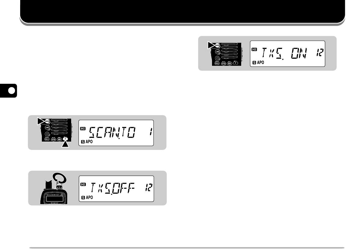
TX INHIBIT
You can disable the TX function to prevent unauthorized
individuals from transmitting, or to eliminate the risk of
accidentally transmitting by yourself.
Access Menu No. 12 (TXS) to switch TX Inhibit ON or
OFF (default).
•Pressing the PTT switch after switching TX Inhibit ON
causes the transceiver to generate an error beep and
display “TXSTOP”.
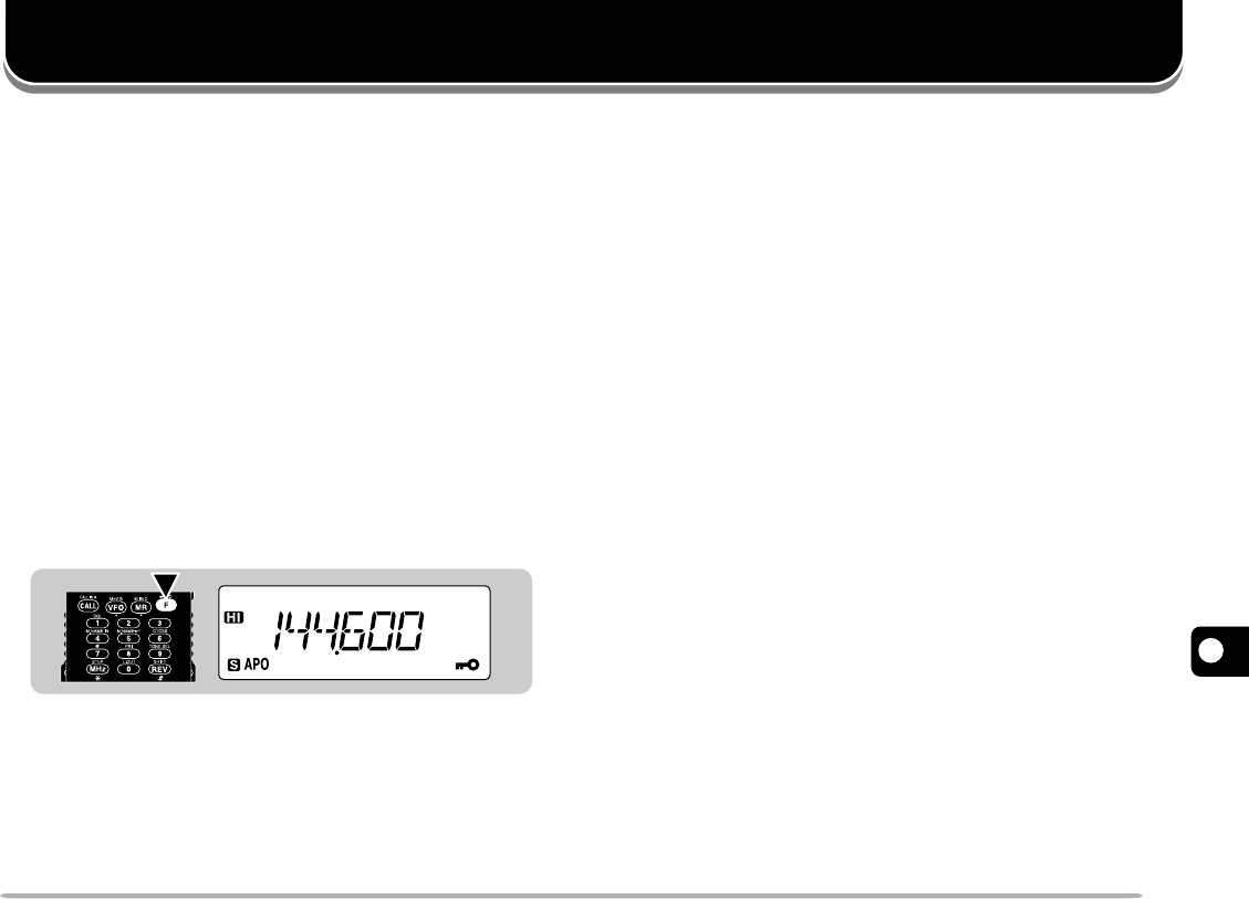
TRANSCEIVER LOCK
This function prevents unauthorized individuals from
changing the transceiver settings.
Press [F] (1 s) to switch the function ON (or OFF).
•A key icon appears when the function is ON.
You may want to use the Tuning control when in
Transceiver Lock mode. Access Menu No. 9 (ENC) to
switch the Tuning Control Enable function ON or OFF
(default).
AUTOMATIC POWER OFF (APO)
Automatic Power Off is a background function that
monitors whether any keys have been pressed, or
whether any control has been turned. After 1 hour
passes with no operations, APO turns OFF the power.
However, 1 minute before the power turns OFF, “APO”
blinks and a series of warning tones sound.
Access Menu No. 5 (APO) to switch the function ON
(default) or OFF.
Note:
◆
If the squelch opens or any settings are changed during the 1 hour
period while APO is ON, the timer resets. When the squelch closes
or you stop changing the settings, the timer begins counting again
from 0.
◆
The APO timer does not operate while Tone Alert or any scan other
than Priority Scan is being used.
BATTERY SAVER
Battery Saver becomes active when the squelch is
closed and no key is pressed for more than 10 seconds.
This function becomes passive whenever the squelch is
opened or any key is pressed.
Access Menu No. 4 (SAV) to switch the function ON
(default) or OFF.
1s
1
2
3
4
5
6
7
8
9
10
11
12
13
14
15
38
LAMP FUNCTION
You can illuminate the transceiver display by pressing
[LAMP]. Approximately 5 seconds after releasing
[LAMP], the light goes OFF if no other key is pressed.
Pressing any key other than [LAMP] while the display is
lit restarts the 5 second timer; pressing [LAMP] turns
OFF the light immediately.
To latch the light ON, press [F], [LAMP]. The light
remains ON until you press [F], [LAMP] again.
BEEP ON/OFF
The transceiver beeps each time you press a key on the
keypad. You can also switch this function OFF.
Access Menu No. 6 (BP) to switch the function ON
(default) or OFF.
SWITCHING AM/FM MODE
(U.S.A./ CANADA ONLY)
Your transceiver can also receive in AM mode.
Select the 118 MHz band, then access Menu No. 16
(F/A) to select FM or AM (default).
•A spade icon appears when you select AM mode.
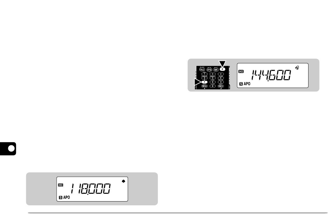
TONE ALERT
Tone Alert provides an audible alarm to indicate when
signals are received on the frequency you are
monitoring. If used with CTCSS, the transceiver beeps
only when receiving the same CTCSS tones as you
selected.
Select the desired band, then press [F], [7] to switch
Tone Alert ON (or OFF).
•A bell icon appears when Tone Alert is ON.
•When receiving correct signals, an alarm sounds and the
bell icon starts blinking. Press the PTT switch to quit Tone
Alert.
•The display shows the number of hours and minutes
elapsed after signals were received. After 99 hours and
59 minutes pass, counting stops. When the next signal was
received, the time resets to 00.00 and counting continues.
Each time a new signal is received, the time resets to 00.00.
Note:
◆
While Tone Alert is ON, there is no speaker output when a signal is
received. To hear receive audio, press
[MONI]
.
◆
When Tone Alert is ON, APO does not turn the power OFF.
◆
When Tone Alert is ON, you can use only the following functions:
•
Lamp ON
•
Lamp Latch ON
•
Monitor
•
Squelch Level Select
2
1
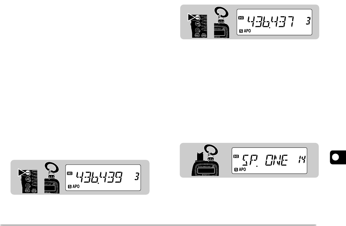
39
1
2
3
4
5
6
7
8
9
10
11
12
13
14
15
PROGRAMMABLE VFO
If you want, you can set limits for the minimum and
maximum frequencies that are selectable using the
Tuning control. For example, if you select 436 MHz for
the lower limit and 437 MHz for the upper limit, the
tunable range will be from 436.000 MHz to
437.975 MHz.
This function will be useful if you always check
frequencies within a certain range.
Note:
◆
You cannot program the 100 kHz and subsequent digits.
◆
The exact 100 kHz and subsequent digits of the upper limit depend
on the step size selected.
◆
You can select the lower and upper limits within the allowable receive
frequency range that differs depending on the markets.
1Press [VFO] to select VFO mode.
2Select the desired band.
3Press [F], [BAND] to enter Menu mode.
4Select Menu No. 3 (PROVFO).
5Press [BAND], then select the lower frequency limit
using the Tuning control.
6Press [BAND] again, then select the upper frequency
limit using the Tuning control.
7Press [BAND] once again to complete the setting.
8Press any key other than [BAND], [LAMP], and
[MONI] to exit Menu mode.
CHANGING SPEAKER CONFIGURATIONS
If using an optional speaker microphone, you can select
whether you will hear audio from only the speaker
microphone or both the speaker microphone and
transceiver. The default is “speaker microphone only”.
1Press [F], [BAND] to enter Menu Mode.
2Select Menu No. 14 (SP).
3Press [BAND] to select “ONE” (default) or “BOTH”.
4Press any key other than [BAND], [LAMP], and
[MONI] to exit Menu mode.
12
12
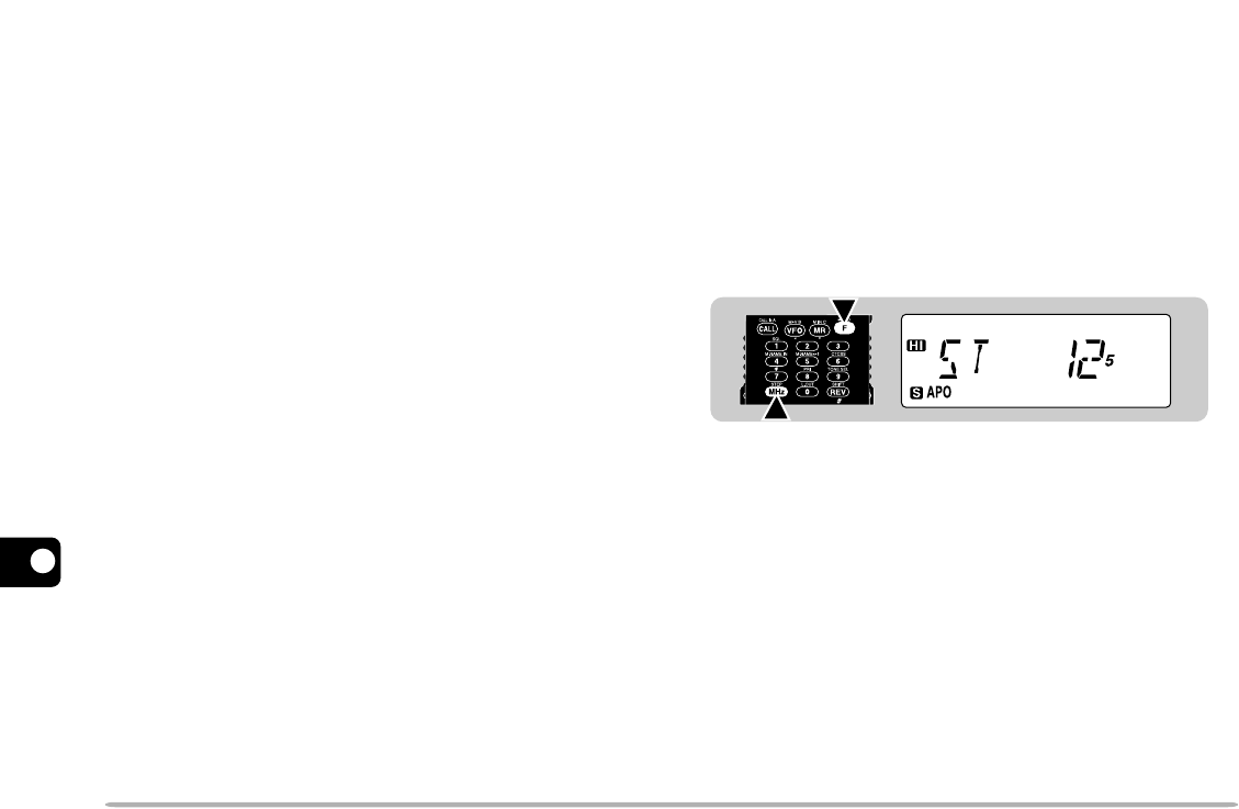
1
2
3
4
5
6
7
8
9
10
11
12
13
14
15
40
KEYPAD DIRECT ENTRY
You can select the desired operating frequency or
memory channel by entering digits directly from the
keypad. Enter the next digit within 10 seconds.
■Frequency Entry
1Press [VFO] to select VFO mode.
2Select the desired band.
3Press the numeric keys in sequence on the
keypad.
•Enter the digits in order from the most significant
down to the least significant.
Note:
◆
When the current step size is 5, 10, 15, 20, 25, 30, 50, or
100 kHz, the 1 kHz digit is corrected according to which key is
pressed for the 1 kHz digit. Pressing
[0]
~
[4]
selects “0” and
pressing
[5]
~
[9]
selects “5”.
◆
When the current step size is 6.25 kHz or 12.5 kHz, the 1 kHz
and subsequent digits are corrected according to which keys are
pressed for the 10 kHz and 1 kHz digits.
■Memory Channel Number Entry
1Press [MR] to enter Memory Recall mode.
•The memory channel used last is recalled.
2Press the numeric keys to enter a 3-digit memory
channel number.
•To recall channel 3, for example, enter “003”.
•If you enter a memory channel that does not contain
data, an error beep sounds.
Note:
You cannot recall a Program Scan channel nor the Priority
channel with keypad direct entry.
CHANGING FREQUENCY STEP SIZE
Choosing the correct step size is essential in order to
select your exact receive frequency using the Tuning
control. The default step size on the VHF band is 5 kHz
(U.S.A./ Canada) or 12.5 kHz (Europe/ General). The
default on the UHF band is 25 kHz no matter which
market version.
1Press [VFO] to select VFO mode.
2Select the desired band.
3Press [F], [MHz].
•The current step size appears.
4Turn the Tuning control to select the desired step
size.
•The selectable step sizes are 5, 6.25, 10, 12.5, 15, 20,
25, 30, 50, and 100 kHz.
5Press any key other than [LAMP] and [MONI] to
complete the setting.
Note:
Changing between step sizes may correct the displayed
frequency. For example, if 144.995 MHz is displayed with a 5 kHz step
size selected, changing to a 12.5 kHz step size corrects the displayed
frequency to 144.9875 MHz.
1
2
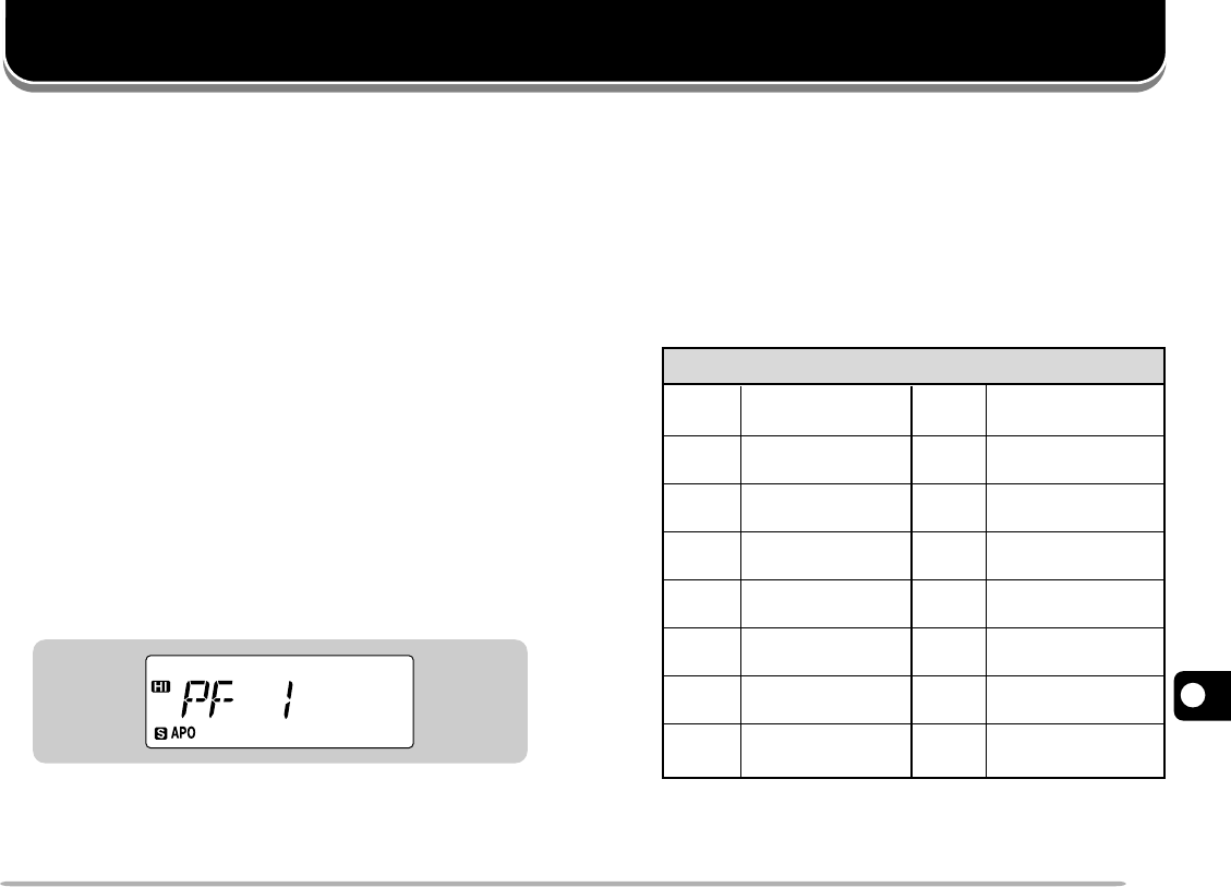
41
1
2
3
4
5
6
7
8
9
10
11
12
13
14
15
MICROPHONE CONTROL
After connecting the optional SMC-33 or SMC-34
speaker microphone, you can change numerous
transceiver settings without using the transceiver keys or
controls. The 1, 2, and 3 keys located on the top of the
microphone are programmable with the transceiver key
(or key combination) function. The assigned default
functions are as follows:
[1]: Band select
[2]: VFO/ Memory Recall mode switch
[3]: Call channel recall (TH-G71E: Transmit power
select)
Note:
◆
Turn OFF the transceiver power before connecting the optional
speaker microphone.
◆
If the
LOCK
switch located on the rear of the microphone is ON, you
cannot re-program the Programmable Function keys.
1Press one of the following key combinations
depending on which key you want to re-program:
Mic [1]+ POWER ON (“PF 1” appears)
Mic [2]+ POWER ON (“PF 2” appears)
Mic [3]+ POWER ON (“PF 3” appears)
2Press a key or key combination on the transceiver
that you want to assign.
•To assign the Up function, rotate the Tuning control
clockwise. To assign the Down function, rotate the
Tuning control counterclockwise.
•Pressing the PTT switch assigns the VFO/MR switch.
•Pressing [0] to [9] allows you to recall a memory
channel number 0 to 9.
•You can assign the following key combinations:
Press [F], then press
[LAMP] Lamp Latch
ON/OFF [8] Priority Scan
ON/OFF
[BAND] Menu mode
select [9] Tone frequency
select
[LOW] Tone ON/OFF [0] Memory Channel
Lockout ON/OFF
[1] Squelch level
select [VFO] Memory ➡ VFO
transfer
[4] Memory name
store [MR] Memory channel
store
[5] Memory name/
frequency change [CALL] Call channel
store
[6] CTCSS ON/OFF [MHz] Frequency step
size select
[7] Tone Alert
ON/OFF [REV] Offset direction
select

1
2
3
4
5
6
7
8
9
10
11
12
13
14
15
42
MAINTENANCE
GENERAL INFORMATION
Your transceiver has been factory aligned and tested to
specification before shipment. All adjustable trimmers,
coils and resistors in the transceiver were preset at the
factory. They should only be readjusted by a qualified
technician who is familiar with this transceiver and has
the necessary test equipment. Attempting service or
alignment without factory authorization can void the
transceiver warranty.
SERVICE
When returning the equipment to your dealer or service
center for repair, pack the transceiver in its original box
and packing material. Include a full description of the
problems experienced. Include both your telephone
number and fax number (if available) along with your
name and address in case the service technician needs
to call you. Don’t return accessory items unless you feel
they are directly related to the service problem.
You may return your transceiver for service to the
authorized KENWOOD dealer from whom you
purchased it or any authorized KENWOOD service
center. A copy of the service report will be returned with
the transceiver. Please do not send subassemblies or
printed circuit boards. Send the complete transceiver.
Tag all returned items with your name and call sign for
identification. Please mention the model and serial
number of the transceiver in any communication
regarding the problem.
SERVICE NOTE
If you desire to correspond on a technical or operational
problem, please make your note short, complete, and to
the point. Help us help you by providing the following:
1Model and serial number of equipment
2Question or problem you are having
3Other equipment in your station pertaining to the problem
4Meter readings
5Other information (Menu setup, mode, frequency, button
sequence to induce malfunction, etc.)
CAUTION:
DO NOT PACK THE EQUIPMENT IN CRUSHED
NEWSPAPERS FOR SHIPMENT! EXTENSIVE DAMAGE MAY RESULT
DURING ROUGH HANDLING OR SHIPPING.
Note:
◆
Record the date of purchase, serial number and dealer from whom
the transceiver was purchased.
◆
For your own information, retain a written record of any maintenance
performed on the transceiver.
◆
When claiming warranty service, please include a photocopy of the
bill of sale, or other proof-of-purchase showing the date of sale.
CLEANING
Remove the controls from the transceiver when they
become soiled and clean them with a neutral detergent
and warm water. Use a neutral detergent (no strong
chemicals) and a damp cloth to clean the case.
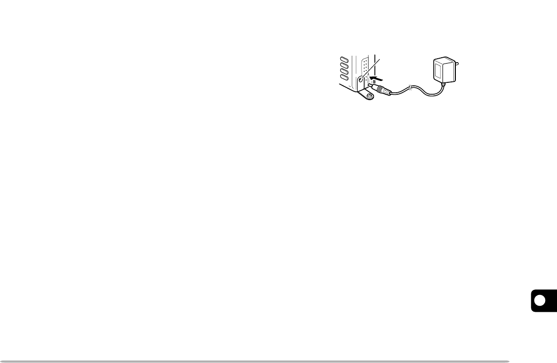
43
1
2
3
4
5
6
7
8
9
10
11
12
13
14
15
CHARGING THE NiCd BATTERY PACK
You must charge the battery pack before using it with the
transceiver, or after storing the pack removed from the
transceiver for more than 2 months. It takes several
charge/ discharge cycles before achieving the full battery
pack capacity.
CAUTION:
◆
EXCEEDING THE SPECIFIED CHARGE PERIOD SHORTENS THE
USEFUL LIFE OF THE NiCd BATTERY PACK.
◆
THE PROVIDED CHARGER IS DESIGNED TO CHARGE ONLY
THE PROVIDED PB-38 OR PB-39 NiCd BATTERY PACK.
CHARGING OTHER MODELS OF BATTERY PACKS WILL
DAMAGE THE CHARGER AND BATTERY PACKS.
Note:
◆
Charging should be done within an ambient temperature between
5
°
C and 40
°
C (41
°
F and 104
°
F). Charging outside this range may
not fully charge the battery.
◆
Always switch OFF the transceiver equipped with the NiCd battery
pack before charging the transceiver. Using the transceiver while
charging its battery pack will interfere with correct charging.
◆
Repeatedly recharging a fully charged battery pack, or almost fully
charged pack, shortens its operating time. To resolve this problem,
use the pack until it is completely discharged. Then recharge the
pack to full capacity.
◆
If the operating time of a battery pack decreases although the battery
pack is fully and correctly charged, the battery pack life is over.
Replace the battery pack.
1Install the NiCd battery pack onto the transceiver
{page 2}.
•Confirm that the transceiver power is OFF.
2Insert the DC plug from the charger into the DC IN
jack on the transceiver.
3Insert the charger AC plug into an AC wall outlet.
•Charging starts and will take approximately 16 hours for
PB-38 or 15 hours for PB-39.
4After 16 hours (PB-38) or 15 hours (PB-39), remove
the charger DC plug from the transceiver DC IN jack.
5Remove the charger AC plug from the AC wall outlet.
DC IN jack

1
2
3
4
5
6
7
8
9
10
11
12
13
14
15
44
TROUBLESHOOTING
The problems described in this table are commonly encountered operational malfunctions. These types of difficulties
are usually caused by improper hook-up, accidental incorrect control settings, or operator error due to incomplete
programming. These problems are usually not caused by circuit failure. Please review this table, and the appropriate
section(s) of this instruction manual, before assuming your transceiver is defective.
Note:
Unmodulated carriers may be received due to internal frequency relationships.
Page
Ref.
Problem Probable Cause Corrective Action
Nothing appears on
the display when the
transceiver is
switched ON, or the
display is blinking
ON and OFF.
1Low supply voltage
2If using the optional DC cable:
a) Bad power cable or connections
b) Open (blown) power supply fuse
1Recharge the battery pack or
replace the batteries.
2
a) Check the power cable and
connections, then correct/replace
as necessary.
b) Investigate the cause for the
open fuse. Replace the fuse.
3, 43
47
—
Most keys and the
Tuning control do
not function.
1Transceiver Lock is ON (Key icon is
visible).
2The transceiver is in Channel Display
mode.
3Tone Alert is ON (Bell icon is visible).
1Press [F] (1 s) to switch OFF
Transceiver Lock.
2Press [BAND]+ POWER ON to exit
Channel Display mode.
3Press [F], [7] to switch OFF Tone
Alert.
37
22
38
Memory channels
cannot be recalled.
There is no data stored in any of the
memory channels.
Store the desired frequencies in
memory channels.
18
You cannot select
the exact desired
frequency using the
Tuning control.
The current frequency step size needs to
be changed.
Select the appropriate frequency step
size.
40

45
1
2
3
4
5
6
7
8
9
10
11
12
13
14
15
You cannot transmit
even though you
press the PTT
switch.
1You selected a frequency outside the
allowable transmit frequency range.
2You selected a transmit offset that
places the transmit frequency outside
the allowable transmit frequency
range.
3 The TX Inhibit function is ON.
4 The Tone Alert function is ON.
1Select a frequency within the
allowable transmit frequency range.
2Press [F], [REV] repeatedly so
neither “+” nor “–” is visible.
3Switch OFF the TX Inhibit function.
4Switch OFF the Tone Alert function.
9
13
37
38
The transceiver
switches OFF for no
apparent reason.
The Automatic Power Off (APO) function
is ON.
Switch OFF the APO function. 37
Packet operation
results in no
connects with other
stations.
1Physical connections between the
transceiver, computer, and TNC are
incorrect, or software settings in the
TNC are wrong.
2Different transmit and receive
frequencies are being used. Usually,
you must use the same transmit and
receive frequency for packet.
3The modulation level from the TNC is
incorrect.
4There is multi-path distortion.
5The squelch is open.
1 Recheck all connections using this
manual, your TNC manual and your
computer hardware manual as
reference.
2If using VFO mode, switch OFF the
transmit offset. If using Memory
Recall, select a simplex memory
channel.
3Adjust the TNC modulation level
according to the TNC manual.
4Reorient the antenna. The
strongest
signal does not always provide the
best operation on packet.
48
13, 17
—
—
8
Page
Ref.
Problem Probable Cause Corrective Action
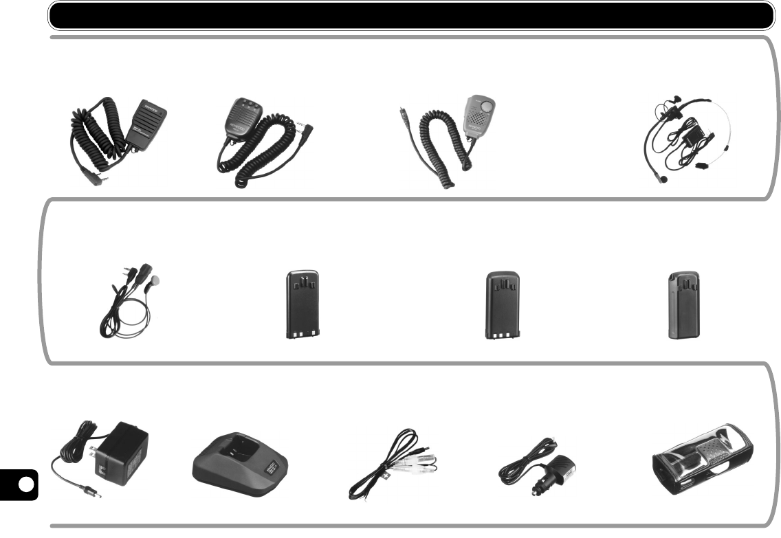
1
2
3
4
5
6
7
8
9
10
11
12
13
14
15
46
OPTIONAL ACCESSORIES
PG-3J
Filtered Cigarette
Lighter Cable
PG-2W
DC Cable
SMC-32
Speaker
Microphone
SMC-33
Remote Control
Speaker Microphone
SMC-34
Remote Control Speaker
Microphone (with Volume Control)
HMC-3
Head Set with
VOX/PTT
BC-17
Wall Charger
BC-19
Rapid Charger
SC-45
Soft Case
BT-11
Battery Case
PB-39
High-power Battery Pack
(9.6 V/ 600 mAh)
PB-38
Standard Battery Pack
(6 V/ 650 mAh)
EMC-3
Clip Microphone
with Earphone
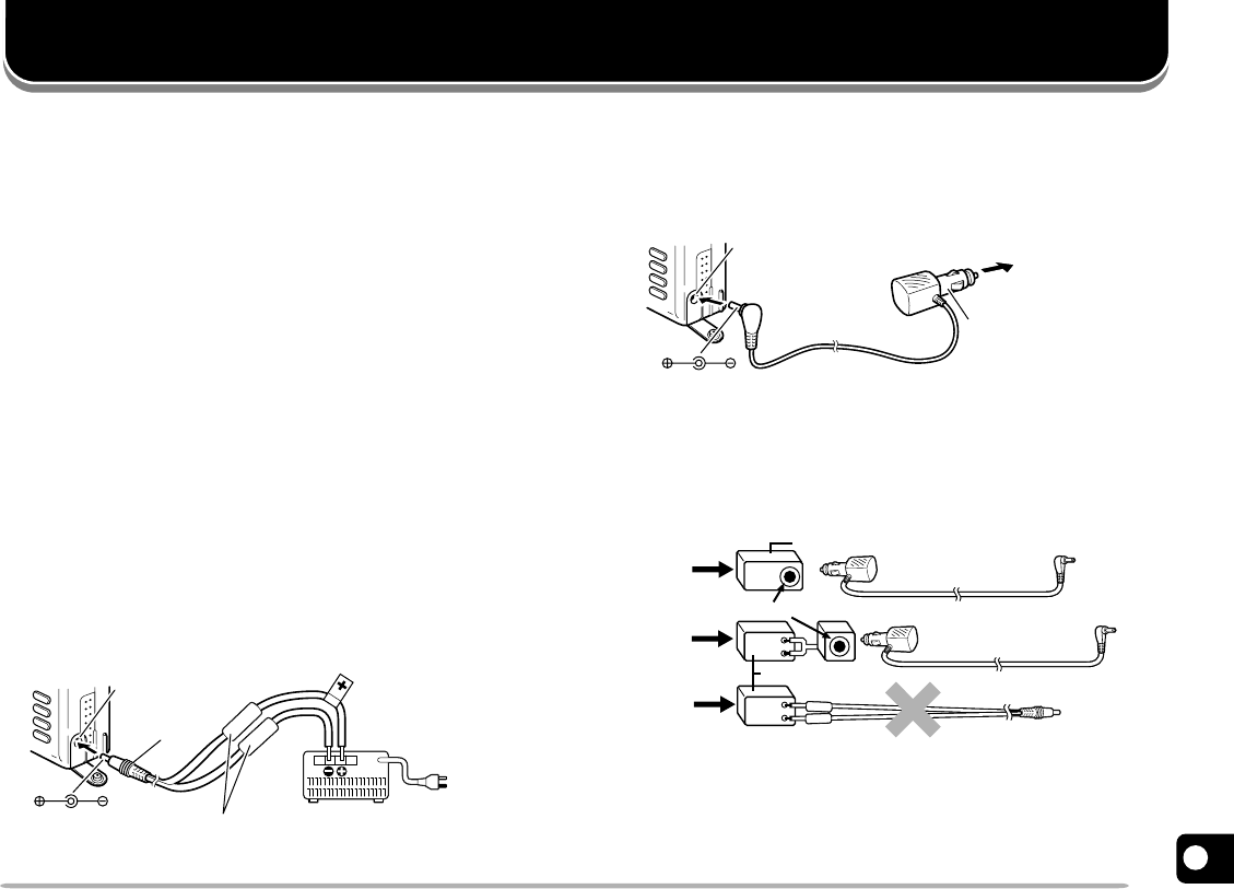
47
1
2
3
4
5
6
7
8
9
10
11
12
13
14
15
EQUIPMENT INSTALLATION AND CONNECTION
CONNECTING AN EXTERNAL POWER SOURCE
You can connect the transceiver to a regulated power
supply via an optional PG-2W cable, or to the cigarette
lighter socket in your vehicle via an optional PG-3J
cable.
Note:
If input voltage exceeds approximately 18 V, warning beeps sound
and “DC ERR” appears on the display.
■Using a Regulated Power Supply
Note:
◆
Switch OFF the transceiver and power supply before making any
connections.
◆
Only use the power supplies recommended by your authorized
KENWOOD
dealer. The supply voltage must be between 6 V
and 16 V to prevent damaging the transceiver.
1Connect the red lead of the optional PG-2W DC
cable to the positive (+) terminal on the power
supply. Connect the black lead of this cable to the
negative (–) terminal.
2Connect the barrel plug on the DC cable to the DC
IN jack on the side of the transceiver.
■Using a Cigarette Lighter Socket
Connect the transceiver to the cigarette lighter socket
in your vehicle using the optional PG-3J Cigarette
Lighter cable.
CAUTION:
TO CONNECT AN EXTERNAL 24 V POWER SOURCE
VIA A DC-DC CONVERTER, ONLY USE THE PG-3J CIGARETTE
LIGHTER CABLE. USING THE PG-2W DC CABLE IN THIS
SITUATION MAY CAUSE A FIRE.
Regulated power supply
To
AC outlet
Black Red
PG-2W
cable
DC IN jack
Fuse
PG-2W
24V
12V
24V PG-3J
12V
12V
24V PG-3J
DC-DC converter
DC-DC converter
Cigarette lighter socket
DC IN jack To Cigarette
lighter
socket
PG-3J cable
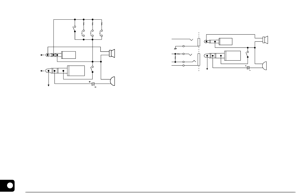
1
2
3
4
5
6
7
8
9
10
11
12
13
14
15
48
CONNECTING EQUIPMENT FOR REMOTE CONTROL
Make connections as shown when remotely controlling
equipment.
Note 1:
Voltage is developed across the 100
Ω
resistor in the 3.5 V line
in the transceiver. When 2 mA flows, approximately 3.3 V is
developed.
Note 2:
A 10
µ
F capacitor is not required in the following cases:
•
When the other equipment has DC blocking capacitors.
•
When a 2-terminal electret condenser microphone is used.
CONNECTING OTHER EXTERNAL EQUIPMENT
When connecting an external speaker, an external
microphone, or other equipment such as a TNC for
packet radio to the SP jack or MIC jack, refer to the
diagram below.
Note 1:
Voltage is developed across the 100
Ω
resistor in the 3.5 V line
in the transceiver. When 2 mA flows, approximately 3.3 V is
developed.
Note 2:
A 10
µ
F capacitor is not required in the following cases:
•
When the other equipment has DC blocking capacitors.
•
When a 2-terminal electret condenser microphone is used.
Speaker
Ground
MIC
Note 2 10µF
PTT switch
PTT
External
speaker,
Note 1
External
microphone,
TNC RX, etc.
TNC TX, etc.
SP
MIC
PTT
Ø2.5
plug
Ø3.5
plug
3.5 V
External
microphone
Ø3.5
plug
Ø2.5
plug
External
speaker
SW-2 10K
SW-3 27K
SW-1 3.9K
Lock SW
MIC jack
Note 1
SP jack 3.5 V
PTT switch
Note 2 10 µF
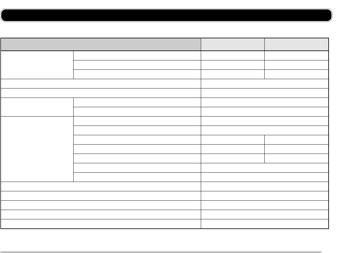
49
1
2
3
4
5
6
7
8
9
10
11
12
13
14
15
Specifications are subject to change without notice due to advancements in technology.
General VHF Band UHF Band
U.S.A./ Canada 144 to 148 MHz 438 to 450 MHz
Frequency range General Market 144 to 148 MHz 430 to 440 MHz
Europe 144 to 146 MHz 430 to 440 MHz
Mode F3E (FM)
Usable temperature range –20°C to +60°C (–4°F to +140°F)
Rated voltage External power supply (DC IN) 5.5 to 16.0 V (13.8 V)
Battery terminals 4.5 to 15.0 V (6.0 V)
Receive with no signals Approx. 70 mA
Battery Saver ON Average 30 mA
Transmit with HI, 13.8 V (DC IN) Approx. 1.7 A Approx. 2.1 A
Current Transmit with HI, 9.6 V (battery terminals) Approx. 1.7 A Approx. 1.8 A
Transmit with HI, 6.0 V (battery terminals) Approx. 1.3 A Approx. 1.5 A
Transmit with LO, 6.0 V (battery terminals) Approx. 500 mA
Transmit with EL, 6.0 V (battery terminals) Approx. 300 mA
Ground method Negative
Dimensions (W x H x D, projections not included) 1
Weight 1, 2 Approx. 330 g/ 11.6 oz
Microphone impedance 2 kΩ
Antenna impedance 50 Ω
1
With a PB-38 installed
2
PB-38, antenna, and belt hook included
54 x 112 x 33.5 mm/ 2.13 x 4.41 x 1.32 in
SPECIFICATIONS
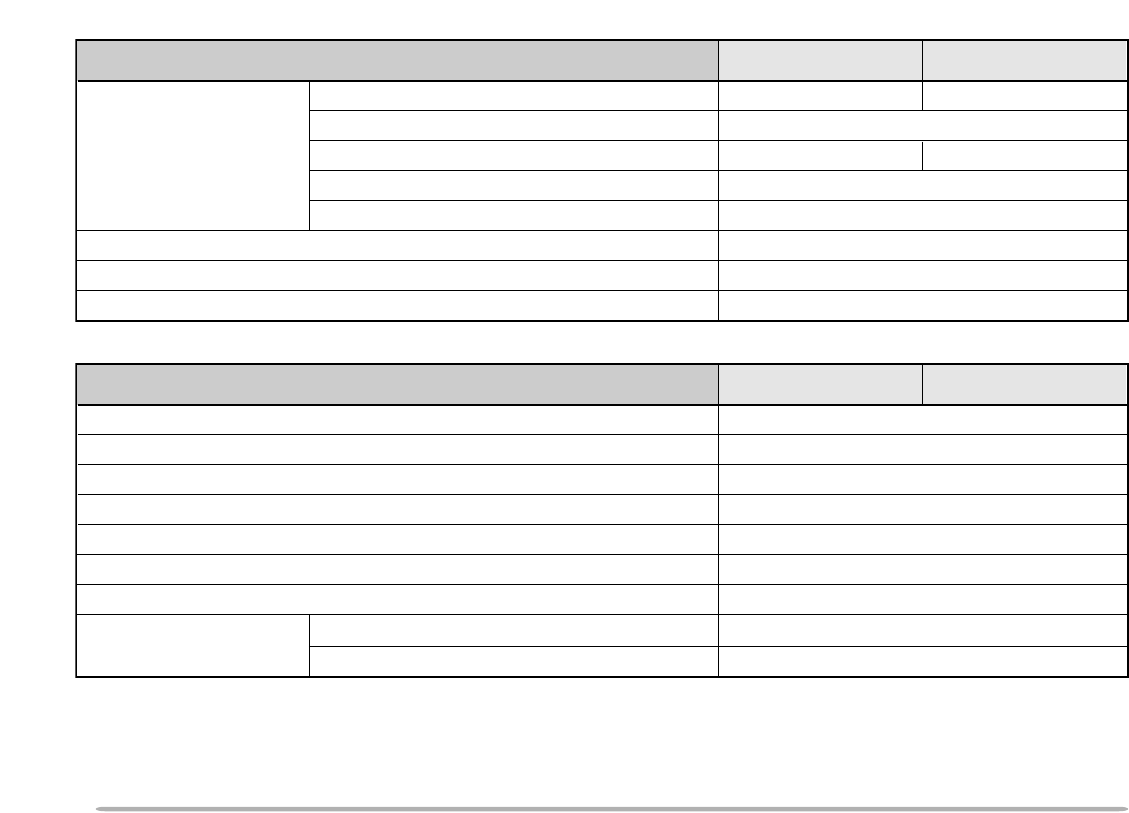
1
2
3
4
5
6
7
8
9
10
11
12
13
14
15
50
Transmitter VHF Band UHF Band
HI, 13.8 V 6 W 5.5 W
HI, 9.6 V Approx. 5 W
Power output HI, 6.0 V Approx. 2.5 W Approx. 2.2 W
LO, 6.0 V Approx. 0.5 W
EL, 6.0 V Approx. 50 mW
Modulation Reactance
Maximum frequency deviation Within ±5 kHz
Spurious emissions –60 dB or less
Receiver VHF Band UHF Band
Circuitry
1st intermediate frequency 38.85 MHz
2nd intermediate frequency 450 kHz
Sensitivity (12 dB SINAD) 0.18 µV or less
Squelch sensitivity 0.1 µV or less
Selectivity (–6 dB) 12 kHz or more
Selectivity (–40 dB) 28 kHz or less
9.6 V (battery terminals) 500 mW or higher (8 Ω load)
6.0 V (battery terminals) 300 mW or higher (8 Ω load)
Audio output
(10% distortion)
Double conversion superheterodyne
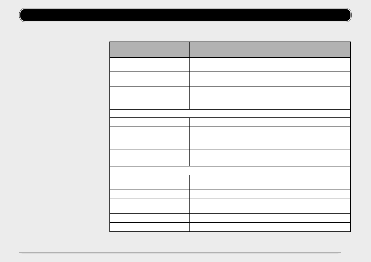
51
QUICK REFERENCE GUIDE
Function Key Operation Ref.
Page
Automatic Power Off
(APO) ON/OFF
[F], [BAND] ➡ Tuning control (Menu No. 5)
➡ [BAND] ➡ [F] 37
37
38
22
32
33
32
40
38
15
13
13
14
14
Battery Saver ON/OFF [F], [BAND] ➡ Tuning control (Menu No. 4)
➡ [BAND] ➡ [F]
Beep ON/OFF [F], [BAND] ➡ Tuning control (Menu No. 6)
➡ [BAND] ➡ [F]
Channel Display ON/OFF POWER OFF ➡ [BAND]+ POWER ON
CTCSS
ON/OFF Select band ➡ [F], [6]
Automatic Tone
Frequency ID ON Select band ➡ [F], [6] (1 s)
Frequency Select Switch CTCSS ON ➡ [F], [9] ➡ Tuning control ➡ [F]
Frequency Step Size Select Select band ➡ [F], [MHz] ➡ Tuning control ➡ [F]
Lamp Latch ON/OFF [F], [LAMP]
Repeater
Automatic Offset (U.S.A./
Canada/ Europe only)
[F], [BAND] ➡ Tuning control (Menu No. 7)
➡ [BAND] ➡ [F]
Offset Direction Select Select band ➡ [F], [REV]
Offset Frequency Select Select band ➡ [F], [BAND] ➡ Tuning control (Menu
No. 8) ➡ [BAND] ➡ Tuning control ➡ [BAND] ➡ [F]
Tone ON/OFF Select band ➡ [F], [LOW]
Tone Frequency Select Switch Tone ON ➡ [F], [9] ➡ Tuning control ➡ [F]
Continued
Note:
◆
This guide covers only the
functions that require a small
number of operation steps.
◆
Some functions ask you to press
any key other than a couple of
keys to complete the setting or to
stop operation. In such a case,
one recommended key is given in
the table.
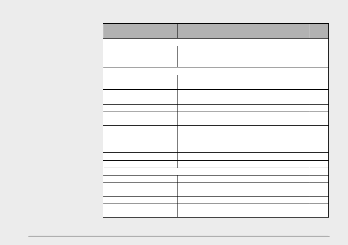
52
Function Key Operation Ref.
Page
Tuning Control Enable [F], [BAND] ➡ Tuning control (Menu No. 9)
➡ [BAND] ➡ [F] 37
Speaker Configuration
Change
[F], [BAND] ➡ Tuning control (Menu No. 14)
➡ [BAND] ➡ [F] 39
37
TX Inhibit ON/OFF [F], [BAND] ➡ Tuning control (Menu No. 12)
➡ [BAND] ➡ [F]
25
Scan Resume Method [F], [BAND] ➡ Tuning control (Menu No. 1)
➡ [BAND] ➡ [F]
26,
27, 29
Scan Stop [CALL], [VFO], [MR], or [MHz] (last key you pressed
to start Scan)
Reset
Transceiver Lock
Scan Start
9
Transmit Power Select Select band ➡ [LOW]
37
ON/OFF [F] (1 s)
38
Tone Alert Select band ➡ [F], [7]
8
Squelch Level Adjust [F], [1] ➡ Tuning control ➡ [F]
29
Call/Memory Select band ➡ [MR] ➡ [CALL] (1 s)
29
Call/VFO [VFO] ➡ Select band ➡ [CALL] (1 s)
26
Memory [MR] (1 s)
27
MHz [VFO] ➡ Select band ➡ [MHz] (1 s)
26
VFO Select band ➡ [VFO] (1 s)
16
Reverse ON/OFF Select band ➡ [REV]
23
Full (memory) POWER OFF ➡ [F]+ POWER ON ➡ [F]
23
Partial (VFO) POWER OFF ➡ [VFO]+ POWER ON ➡ [VFO]

53
1
2
3
4
5
6
7
8
9
10
11
12
13
14
15
INDEX
Accessories
Optional ........................................ 46
Supplied .......................................... 1
Automatic Power Off (APO) .............. 37
Automatic Tone Frequency ID ........... 33
Autopatch (U.S.A. and Canada) ........ 34
Battery
Charging ....................................... 43
Installing, Alkaline ............................ 3
Installing, NiCd ................................ 2
Battery Saver ..................................... 37
Band, Selecting ................................... 9
Beep ON/OFF .................................... 38
Call Channel
Contents, Changing ...................... 21
Recalling ....................................... 21
Channel Display Function ................. 22
Connection
Cigarette Lighter ............................ 47
Regulated Power Supply ............... 47
Continuous Tone Coded
Squelch System (CTCSS)
Automatic Tone Frequency ID ....... 33
Using ............................................ 32
Dual Tone Multi-Frequency
(DTMF) Functions
Confirming Stored Numbers .......... 35
Making Calls ................................. 34
Storing Numbers ........................... 35
Tone TX Hold ................................ 34
Transmitting Stored Numbers ........ 36
Frequency, Selecting ..................... 9, 40
Frequency Step Size ......................... 40
Installation
Antenna .......................................... 4
Belt hook ......................................... 4
Hand strap ...................................... 4
Keypad Direct Entry
Frequency ..................................... 40
Memory Channel Number ............. 40
Lamp Function ................................... 38
Lock, Transceiver .............................. 37
Maintenance ...................................... 42
Memory Channels
Clearing ........................................ 19
Direct Number Entry ...................... 40
Initializing ...................................... 23
Locking Out ................................... 27
Naming ......................................... 20
Recalling ....................................... 19
Storing, Odd-split .......................... 18
Storing, Simplex&Repeater ........... 18
Transfer to VFO ............................ 22
Menu .................................................. 10
Microphone Control ........................... 41
Offset
Automatic Repeater ...................... 15
Offset Direction ............................. 13
Offset Frequency ........................... 13
Power, ON/OFF ................................... 8
Programmable VFO ........................... 39
Repeater Access ............................... 12
Reset
Full (Memory) ................................ 23
Partial (VFO) ................................. 23
Reverse Function .............................. 16
Scan
Call/Memory .................................. 29
Call/VFO ....................................... 29
Memory ......................................... 26
MHz .............................................. 27
Priority ........................................... 30
Program ........................................ 28
VFO .............................................. 26
Scan Resume
Carrier-Operated ........................... 25
Seek ............................................. 25
Time-Operated .............................. 25
Specifications..................................... 49
Squelch, Adjusting ............................... 8
Time-Out Timer (TOT) ......................... 9
Tone
Activating ...................................... 14
Frequency, Selecting ..................... 14
Tone Alert ........................................... 38
Transmit Power, Selecting ................... 9
Troubleshooting ................................. 44
TX Inhibit ............................................ 37
Volume, Adjusting ................................ 8