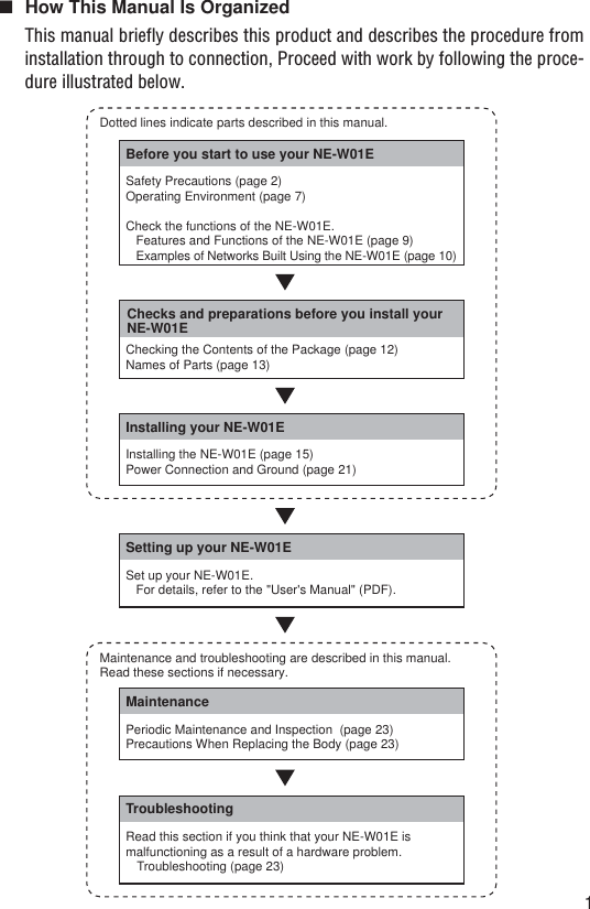
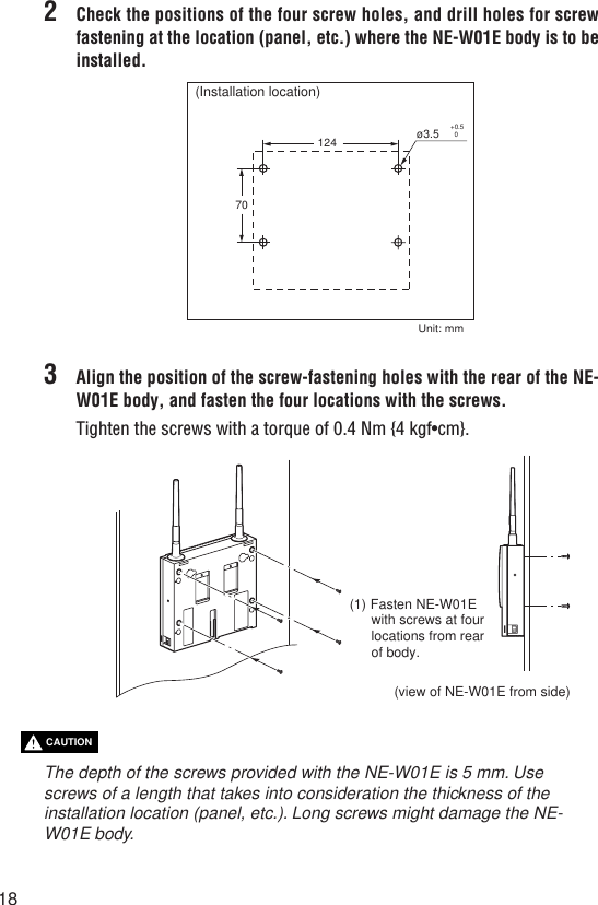
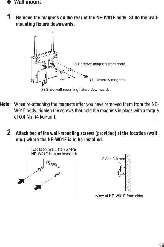
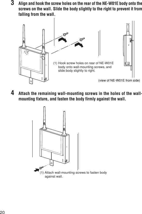
Keyence 0718 NE-W01E and NE-W11E WLAN Routers User Manual W01E Instruction Manual
Keyence Corporation NE-W01E and NE-W11E WLAN Routers W01E Instruction Manual
Keyence >
Contents
- 1. W01E Instruction Manual
- 2. W11E Instruction Manual
W01E Instruction Manual
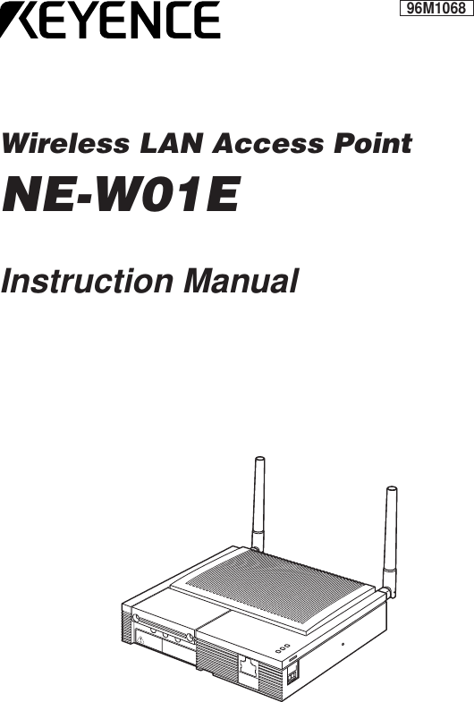
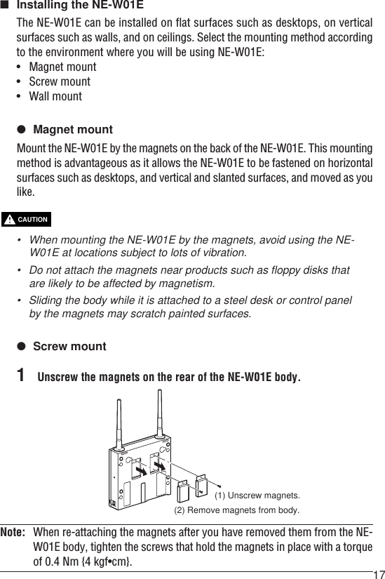
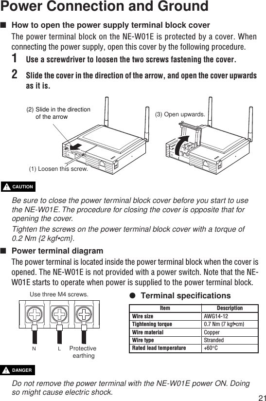
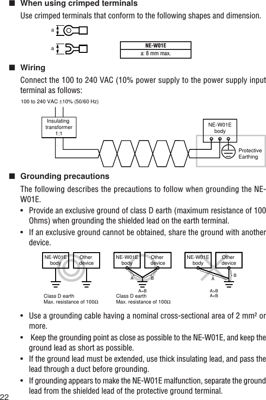
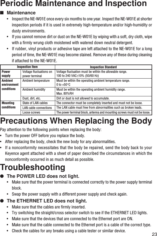
![DANGERWARNINGCAUTIONPrefaceThis manual describes how to install and connect the Wireless LAN Access Point NE-W01E.To ensure full use of the Wireless LAN Access Point NE-W01E, be sure to thoroughlyread this manual, and fully understand the functions of the NE-W01E before use.Store this manual in a safe place so that you can retrieve it whenever necessary.■SymbolsThis manual uses the following symbols to alert you to important information.Failure to follow these instructions may lead to death or serious injury.Failure to follow these instructions may lead to injury.Failure to follow these instructions may lead to physical damage(product malfunction, etc.).Important: Provides additional information on precautions and restrictions thatmust be followed in operation.Note: Provides additional information on proper operation.[Tip]Indicates useful information or information that aids understanding of textdescriptions.Indicates a reference item or page to be referred to in this manual and a separatemanual.■Request(1) No part of this instruction may be reprinted or reproduced without the priorwritten permission of KEYENCE CORPORATION.(2) The contents of this manual are subject to change without notice.(3) Every effort has been made in preparing this document. If, however, you find anyunclear points, errors, omissions or other inconsistencies, please feel free tocontact us.(4) Note that KEYENCE CORPORATION shall not be liable for any influence resultingfrom operation of the Wireless LAN Access Point NE-W01E regardless of item(3) above.(5) We shall replace any missing or incorrectly collated pages.](https://usermanual.wiki/Keyence/0718.W01E-Instruction-Manual/User-Guide-361398-Page-2.png)