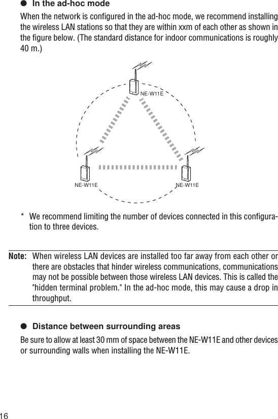
Keyence 0718 NE-W01E and NE-W11E WLAN Routers User Manual W11E Instruction Manual
Keyence Corporation NE-W01E and NE-W11E WLAN Routers W11E Instruction Manual
Keyence >
Contents
- 1. W01E Instruction Manual
- 2. W11E Instruction Manual
W11E Instruction Manual
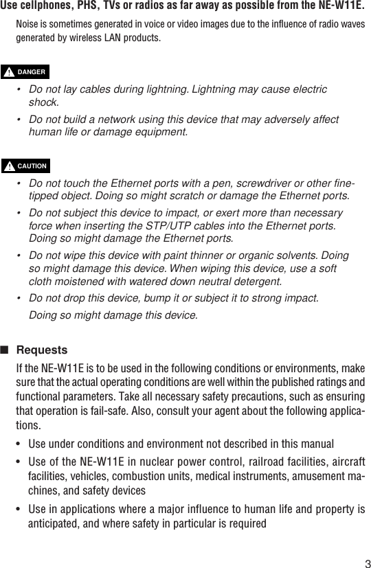
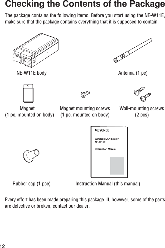
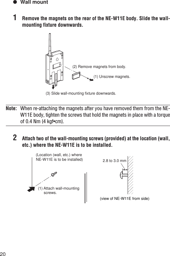
![DANGERWARNINGCAUTIONPrefaceThe NE-W11E is a wireless device that performs communications between the NE-W01E (access point) and the NE-W11E (station).This manual describes how to install and connect the Wireless LAN Station NE-W11E.To ensure full use of the Wireless LAN Station NE-W11E, be sure to thoroughly readthis manual, and fully understand the functions of the NE-W11E before use. Storethis manual in a safe place so that you can retrieve it whenever necessary.■SymbolsThis manual uses the following symbols to alert you to important information.Failure to follow these instructions may lead to death or serious injury.Failure to follow these instructions may lead to injury.Failure to follow these instructions may lead to physical damage(product malfunction, etc.).Important: Provides additional information on precautions and restrictions thatmust be followed in operation.Note: Provides additional information on proper operation.[Tip]Indicates useful information or information that aids understanding of textdescriptions.Indicates a reference item or page to be referred to in this manual and a separatemanual.■Request(1) No part of this instruction may be reprinted or reproduced without the priorwritten permission of KEYENCE CORPORATION.(2) The contents of this manual are subject to change without notice.(3) Every effort has been made in preparing this document. If, however, you find anyunclear points, errors, omissions or other inconsistencies, please feel free tocontact us.(4) Note that KEYENCE CORPORATION shall not be liable for any influence resultingfrom operation of the Wireless LAN Station NE-W01E regardless of item (3)above.(5) We shall replace any missing or incorrectly collated pages.](https://usermanual.wiki/Keyence/0718.W11E-Instruction-Manual/User-Guide-361399-Page-2.png)

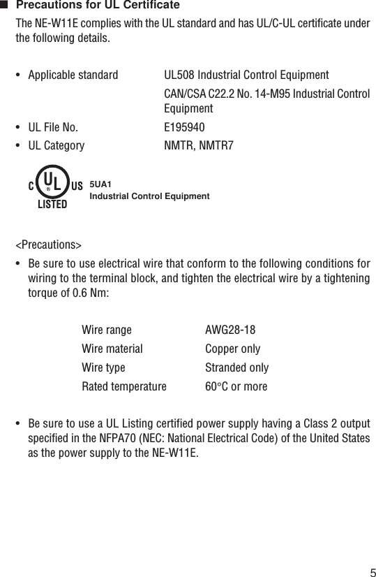
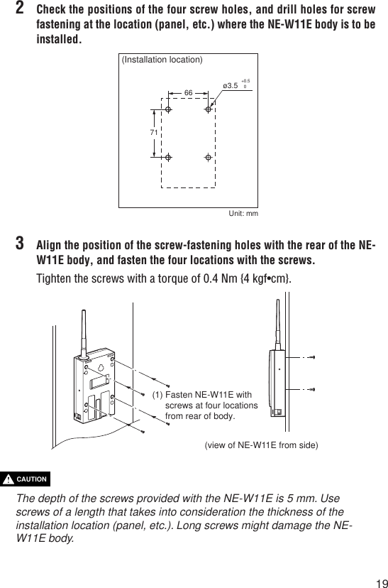
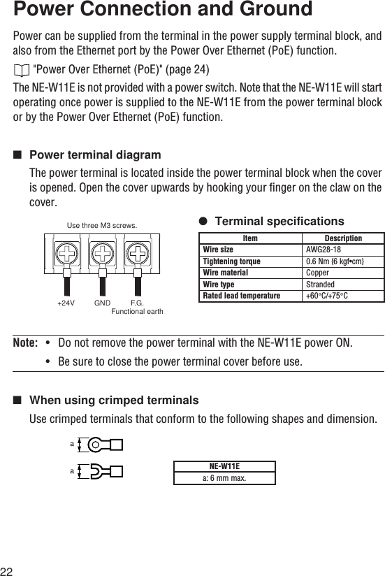
![24Power Over Ethernet (PoE)The NE-W11E's Power Over Ethernet (PoE) function supplies power to the NE-W11Efrom the Keyence Corporation Ethernet Switch NE-V08 or Data Storage TerminalDT-100 via the STP cable* provided. By this function, power need not be connectedto the terminal block as power is supplied from the Ethernet port.To use the PoE function, set the power selector switch on the bottom of the body to"PoE". When the NE-W11E is connected to the NE-V08 or the DT-100, do not connectto other network devices such as a hub in between by the Keyence Corporation STPcable.[Tip] For details on the PoE function on the power supplying side NE-V08 or DT-100, refer to the various manuals or instruction manuals for the respectiveproduct.•Use the PoE function of the NE-W11E only on devices made byKeyence Corporation that incorporate this function.•Power supply from the power terminal block cannot be used at thesame time as the Power Over Ethernet (PoE) function.•When the NE-W11E is connected to a device made by KeyenceCorporation that incorporates this function using the KeyenceCorporation STP cable, do not connect other network devices suchas a hub in between.*Keyence Corporation STP CableOP-51504 (0.2 m)OP-51505 (0.5 m)OP-51506 (1 m)OP-51507 (3 m)OP-51508 (5 m)CAUTIONDT-100Othermanufacturer's PLCOther communi-cations device(without PoE function)NE-W11E NE-V08Keyence STP cableRS-232C/422 cableKeyence STP cablePower is supplied to NE-W11E by PoE function.Power is supplied to NE-W11E by PoE function.Connect to 24 VDC power supply.NE-W11EConnect to 24 VDC power supply.EXT PoESet power selector switch to "PoE side".(Default setting is "EXT".)](https://usermanual.wiki/Keyence/0718.W11E-Instruction-Manual/User-Guide-361399-Page-26.png)