Keyence 0718 NE-W01E and NE-W11E WLAN Routers User Manual W11E Instruction Manual
Keyence Corporation NE-W01E and NE-W11E WLAN Routers W11E Instruction Manual
Keyence >
Contents
- 1. W01E Instruction Manual
- 2. W11E Instruction Manual
W11E Instruction Manual
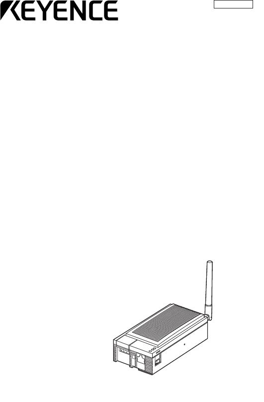
Wireless LAN Station
NE-W11E
Instruction Manual
96M1069
DANGER
WARNING
CAUTION
Preface
The NE-W11E is a wireless device that performs communications between the NE-
W01E (access point) and the NE-W11E (station).
This manual describes how to install and connect the Wireless LAN Station NE-
W11E.
To ensure full use of the Wireless LAN Station NE-W11E, be sure to thoroughly read
this manual, and fully understand the functions of the NE-W11E before use. Store
this manual in a safe place so that you can retrieve it whenever necessary.
■Symbols
This manual uses the following symbols to alert you to important information.
Failure to follow these instructions may lead to death or serious injury.
Failure to follow these instructions may lead to injury.
Failure to follow these instructions may lead to physical damage
(product malfunction, etc.).
Important: Provides additional information on precautions and restrictions that
must be followed in operation.
Note: Provides additional information on proper operation.
[Tip]
Indicates useful information or information that aids understanding of text
descriptions.
Indicates a reference item or page to be referred to in this manual and a separate
manual.
■Request
(1) No part of this instruction may be reprinted or reproduced without the prior
written permission of KEYENCE CORPORATION.
(2) The contents of this manual are subject to change without notice.
(3) Every effort has been made in preparing this document. If, however, you find any
unclear points, errors, omissions or other inconsistencies, please feel free to
contact us.
(4) Note that KEYENCE CORPORATION shall not be liable for any influence resulting
from operation of the Wireless LAN Station NE-W01E regardless of item (3)
above.
(5) We shall replace any missing or incorrectly collated pages.
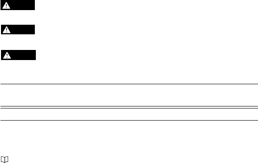
■How This Manual Is Organized
This manual briefly describes this product and describes the procedure from
installation through to connection, Proceed with work by following the proce-
dure illustrated below.
Dotted lines indicate parts described in this manual.
Before you start to use your NE-W11E
Safety Precautions (page 2)
Operating Environment (page 7)
Check the functions of the NE-W11E.
Features and Functions of the NE-W11E (page 9)
Examples of Networks Built Using the NE-W11E (page 10)
Setting up your NE-W11E
Set up your NE-W11E.
For details, refer to the "User's Manual" (PDF).
Checks and preparations before you install your
NE-W11E
Checking the Contents of the Package (page 12)
Names of Parts (page 13)
Installing your NE-W11E
Installing the NE-W11E (page 15)
Power Connection and Ground (page 22)
Maintenance and troubleshooting are described in this manual.
Read these sections if necessary.
Maintenance
Periodic Maintenance and Inspection (page 25)
Precautions When Replacing the Body (page 25)
Troubleshooting
Read this section if you think that your NE-W11E is
malfunctioning as a result of a hardware problem.
Troubleshooting (page 26)
1
2
Safety Precautions
■General Precautions
•At startup and during operation, be sure to monitor the functions and performance of the
NE-W11E.
•We recommend that you take substantial safety measures to avoid any damage in the
event that a problem occurs.
•Do not modify the NE-W11E or use it in any way other than described in the specifica-
tions. The functions and performance of products used or modified in this way cannot
be assured.
•When the NE-W11E is used in combination with other equipment, functions and
performance may be degraded depending on operating conditions, surrounding envi-
ronment and other factors. Fully take this into consideration before using the NE-W11E
in this way.
•Do not subject instruments including peripheral devices to sudden changes in tempera-
ture. Doing so might cause condensation which may cause the instrument or device to
malfunction.
•Mount the NE-W11E as far away as possible from power lines or high-voltage lines. Noise
from power lines and high-voltage lines may cause the NE-W11E to malfunction.
•NE-W11E is not a general purpose equipment suitable for use by the average consumer.
• NE-W11E is not a product safe to use for domestic use.
•NE-W11E has reduced safety features and must only be used under specific environmen-
tal conditions.
•NE-W11E has reduced safety features and product must only be used by technically
skilled persons.
Do not use the NE-W11E near the following items:
●Medical equipment such as pacemakers
The NE-W11E might cause electrical interference with medical equipment or pacemakers,
and endanger human life.
●Microwave ovens and other electronic household items, in-site
wireless nodes (requiring a license) for mobile recognition that
are used in factory production lines, etc., and specific small-
power wireless nodes (not requiring a license)
The NE-W11E might cause electrical interference, resulting in a drop in communications
speed, loss of data or diminished transfer distance.
Should radio wave interfere with in-site wireless modes for mobile recognition and specific
small-power wireless nodes be generated from the NE-W11E, change the frequency of the
NE-W11E to prevent radio wave interference from occurring.

3
Use cellphones, PHS, TVs or radios as far away as possible from the NE-W11E.
Noise is sometimes generated in voice or video images due to the influence of radio waves
generated by wireless LAN products.
•Do not lay cables during lightning. Lightning may cause electric
shock.
•Do not build a network using this device that may adversely affect
human life or damage equipment.
•Do not touch the Ethernet ports with a pen, screwdriver or other fine-
tipped object. Doing so might scratch or damage the Ethernet ports.
•Do not subject this device to impact, or exert more than necessary
force when inserting the STP/UTP cables into the Ethernet ports.
Doing so might damage the Ethernet ports.
• Do not wipe this device with paint thinner or organic solvents. Doing
so might damage this device. When wiping this device, use a soft
cloth moistened with watered down neutral detergent.
•Do not drop this device, bump it or subject it to strong impact.
Doing so might damage this device.
■Requests
If the NE-W11E is to be used in the following conditions or environments, make
sure that the actual operating conditions are well within the published ratings and
functional parameters. Take all necessary safety precautions, such as ensuring
that operation is fail-safe. Also, consult your agent about the following applica-
tions.
• Use under conditions and environment not described in this manual
•Use of the NE-W11E in nuclear power control, railroad facilities, aircraft
facilities, vehicles, combustion units, medical instruments, amusement ma-
chines, and safety devices
•Use in applications where a major influence to human life and property is
anticipated, and where safety in particular is required
CAUTION
DANGER
4
■Precautions for CE Marking
The NE-W11E is subject to the R&TTE Directive. Keyence Corporation has
evaluated compliance with the requirements of the R&TTE Directive when the
following conditions were satisfied, and has confirmed that the NE-W11E
satisfies those requirements.
<Requirements>
● Precautions for R&TTE Directive (1999/5/EC)
•Applicable standards ETSI EN301 489-17
ETSI EN300 328-2
EN61010-1
•Notified body NEMKO (Norway)
•Overvoltage category I
•Pollution degree 2
•The NE-W11E can be used in the following countries within the EU region:
•Austria
•Greece
•Norway
* The NE-W11E cannot be used in France or Spain.
•11 channels can be selected.
•Belgium
• Iceland
•Portugal
•Denmark
•Ireland
•Sweden
•Finland
•Italy
•United
Kingdom
•Germany
•Luxem-
bourg
•Holland

5
■Precautions for UL Certificate
The NE-W11E complies with the UL standard and has UL/C-UL certificate under
the following details.
•Applicable standard UL508 Industrial Control Equipment
CAN/CSA C22.2 No. 14-M95 Industrial Control
Equipment
•UL File No. E195940
•UL Category NMTR, NMTR7
5UA1
Industrial Control Equipment
LISTED
USC
UL
<Precautions>
•Be sure to use electrical wire that conform to the following conditions for
wiring to the terminal block, and tighten the electrical wire by a tightening
torque of 0.6 Nm:
Wire range AWG28-18
Wire material Copper only
Wire type Stranded only
Rated temperature 60°C or more
•Be sure to use a UL Listing certified power supply having a Class 2 output
specified in the NFPA70 (NEC: National Electrical Code) of the United States
as the power supply to the NE-W11E.
■ Precautions for FCC
The NE-W01E falls under the category of intentional radiowave-emitting devices
stipulated in FCC Part 15 subpart C. Keyence Corporation has evaluated
compliance with the requirements of FCC Part 15 subpart C, and has confirmed
that the NE-W01E satisfies those requirements.
This equipment has been tested and found to comply with the limits for a
Class B digital device, pursuant to Part 15 of the FCC Rules. These limits are
designed to provide reasonable protection against harmful interference in a
residential installation. This equipment generates, uses and can radiate radio
frequency energy and, if not installed and used in accordance with the
instructions, may cause harmful interference to radio communications. However,
there is no guarantee that interference will not occur in a particular installation.
If this equipment does cause harmful interference to radio or television reception,
which can be determined by turning the equipment off and on, the user is
encouraged to try to correct the interference by one or more of the following
measures:
-- Reorient or relocate the receiving antenna.
-- Increase the separation between the equipment and receiver.
-- Connect the equipment into an outlet on a circuit different
from that to which the receiver is connected.
Consult the dealer or an experienced radio/TV technician for help.
You are cautioned that changes or modifications not expressly approved by the
party responsible for compliance could void your authority to operate the
equipment.
The NE-W01E cannot be used with a device other than the antenna (provided)
mounted. When the NE-W01E is replaced, for example, due to antenna damage,
be sure to purchase and mount an antenna exclusively for the NE-W01E.
<RF exposure information>
This device complies with FCC RF radiation exposure limits set forth for an
uncontrolled environment. The antenna used for this transmitter must be installed to
provide a separation distance of at least 20 cm from all persons and must not be
co-located or operating in conjunction with any other antenna or transmitter.
6
7
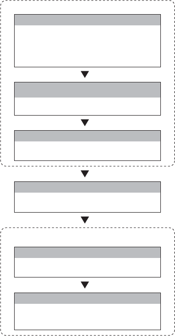
Operating Environment
■Installation location
Do not install the NE-W11E in the following locations.
Locations subject to direct sun-
light
Locations subject to ambient temper-
ature out of the 0 to +50°C range
Locations subject to ambient humid-
ity out of the 35 to 80%RH range
Locations subject to condensa-
tion caused by sudden tempera-
ture change
Locations subject to corrosive
and flammable gases Locations subject to large
amounts of dirt and dust, salt,
iron and oil smoke
Locations directly subject to vibra-
tion and shock Locations that may be splashed
with water, oil or chemical mist Locations where strong magnetic
and electrical fields are gener-
ated
Chemicals
oil
Electrical
field
Magnetic
field
Note: Install the NE-W11E as far away as possible from locations where radios, etc.
are located. Radio waves emitted by the NE-W11E may cause noise to occur
on the radio.
8
■Installation location precautions
Pay attention to the following points when installing the NE-W11E.
•Do not install the NE-W11E in a location where the ambient temperature
exceeds the 0 to +50°C range or the ambient humidity exceeds the 35 to
80%RH range.
•If the ambient temperature exceeds the above range, install a forced air
cooling fan or air conditioner to keep the ambient temperature within this
range.
•Allow as much space as possible between the NE-W11E and surrounding
structures and other components to improve maintainability, operability and
ventilation.
•Do not mount the NE-W11E directly above equipment (e.g. heaters, trans-
formers, inverters and equipment with large resistance) that generate lots of
heat.
■Measures for improving noise resistance
•Do not mount the NE-W11E inside industrial control panels in which high-voltage
devices are also located.
•Mount the NE-W11E as far away as possible from power lines.
•Mount the NE-W11E as far away as possible when it must be mounted next to
devices (e.g. solenoids, choppers, etc.) that generate strong magnetic and
electrical fields.
•Do not include the NE-W11E I/O leads in the same ducts as power lines and high-
voltage lines. Wire the I/O leads in separate ducts. Noise from power lines and high-
voltage lines may cause malfunction on the NE-W11E.
•Provide a Class D earth (maximum resistance of 100 Ohms) for the protective
ground terminal.
9
Features and Functions of the NE-W11E
Wireless LAN Station NE-W11E is a station for wireless LAN communications that
is compliant with IEEE802.11b.
■IEEE802.11b compliant
NE-W11E is compliant with the IEEE802.11b standard , and is capable of high-
speed wireless communications of 11 Mbps (logical value).
■Wiring by cables is no longer required, allowing the configuration
of a wireless network.
Wiring by conventional network cables is no longer required. This allows you to
install PCs and other wireless LAN devices as you like.
■Integrated security functions
Data is encrypted by the WEP (Wired Equivalent Privacy) function to protect
valuable data. (64-bit WEP and 128-bit WEP modes are supported.)
■Power Over Ethernet (PoE) function
This device supports the Power Over Ethernet (PoE) function, a function that
enables power to be supplied via the Ethernet port. Connection of the power
supply terminal is no longer required as you need only connect to devices made
by Keyence Corporation that incorporate the PoE function.
10
Examples of Networks Built Using NE-
W11E
A wireless LAN network can be built by combining NE-W11E with Wireless LAN
Access Point NE-W01E. Wireless LANs operate in two communications modes:
infrastructure mode and ad-hoc mode. The applicable mode varies according to
what kind of network you are going to configure by the wireless LAN. For this reason,
check which communications mode will be used referring to the network configu-
ration examples below.
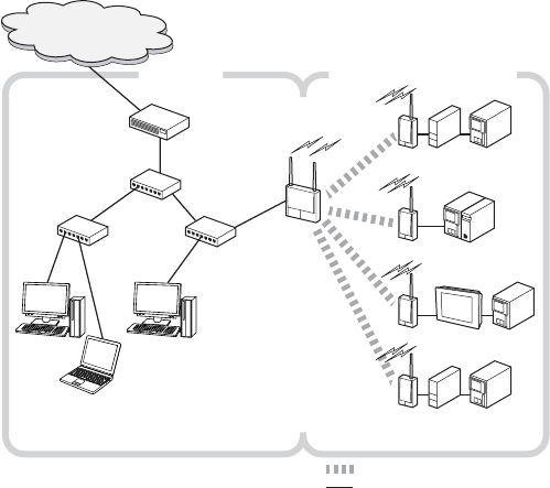
■Example of a network built in the infrastructure mode
In relatively large-scale networks where the user wants to add on a wireless LAN
network to an existing wired LAN network or access the Internet from a wireless
LAN network, access points are used to configure a network in the infrastructure
mode.
●Example 1
Router/modem, etc.
Headquarters network,
Internet, etc.
HUB
HUBHUB
NE-W01E
NE-W11E
NE-W11E
NE-W11E VT2
DT Other
manufacturer's
PLC
NE-W11E DT
KV-700 KV-LE20
Factory, production site, etc.Office, etc.
: Wireless LAN communications
: Wired connection
Other
manufacturer's
PLC
Other
manufacturer's
PLC
11
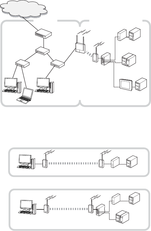
■Example of a network built in the ad-hoc mode
In relatively small-scale networks where the user wants to enable communica-
tions between PCs or wireless LAN devices at remote locations, the network is
configured in the ad-hoc mode.
●Example 1
●Example 2
●Example 2
DT Other manufacturer's
PLC
NE-W11ENE-W11E
DT Other manufacturer's
PLC
KV-700 KV-LE20
NE-W11E
NE-V08
NE-W11E
Headquarters network,
Internet, etc.
VT2
DT
Other
manufacturer's
PLC
KV-700 KV-LE20
Factory, production site, etc.Office, etc.
Other
manufacturer's
PLC
Router/modem, etc.
HUB
HUBHUB
NE-W01E
NE-W11E
NE-V08
12
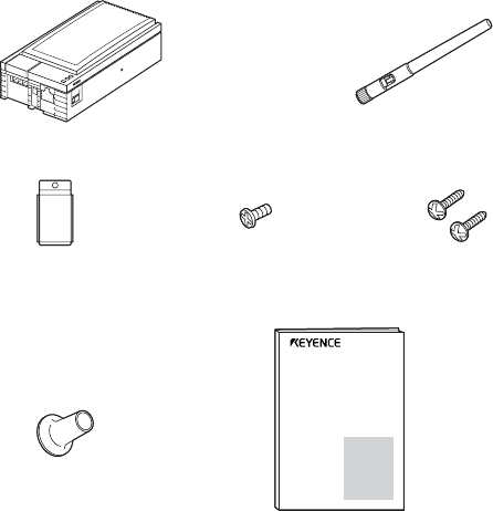
Checking the Contents of the Package
The package contains the following items. Before you start using the NE-W11E,
make sure that the package contains everything that it is supposed to contain.
NE-W11E body Antenna (1 pc)
Magnet Magnet mounting screws Wall-mounting screws
(1 pc, mounted on body) (1 pc, mounted on body) (2 pcs)
Rubber cap (1 pce) Instruction Manual (this manual)
Every effort has been made preparing this package. If, however, some of the parts
are defective or broken, contact our dealer.
Wireless LAN Station
NE-W11E
Instruction Manual
13
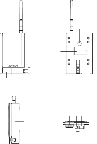
Names of Parts
■Front view ■Rear view
■Side view ■Bottom view
(1)
(2)
(3)
(4)
POWER
WIRELESS
ETHERNET
(5) (6)
(8)
(7)
(8)
(8)
(6)
(8)
(9)
(11) (12)(13)
(10)
14
Description
Antenna (1 pc)
This LED lights (green) when the unit is energized.
This LED indicates the state of wireless LAN communications.
Lit: The wireless LAN link is established.
Blinking: Communications is in progress.
Out: The wireless LAN link is not established.
This LED indicates the state of the Ethernet port.
Lit: The link with the destination device is established.
Blinking: Data communications is in progress.
Out: Either the cable is not connected, or the link is not connected.
This cover protects the power supply terminal block.
( "Power Connection and Ground" page 22)
These two holes are for hooking the wall-mounting screws after the screws have been
fixed on the wall when the body is to be wall-mounted.
( "Installing the NE-W11E" page 15)
This magnet is for fastening the body in place.
( "Installing the NE-W11E" page 15)
These 4 holes are used for fastening the body in place with the M3 screws.
( "Installing the NE-W11E" page 15)
This switch is used to return setting values to their defaults (factory settings).
"Defaults (factory settings)" (page 29)
This switch is for selecting straight or cross connections.
: Straight
: Cross
This terminal block is for 24 VDC power input.
( "Power terminal diagram" page 22)
This switch switches the power input method.
EXT: This routes power into the NE-W11E from the terminal block.
PoE: This routes power into the NE-W11E from the Ethernet port by the Power Over
Ethernet (PoE) function.
( "Power terminal diagram" (page 22), "Power Over Ethernet (PoE)" (page
24))
This is a 10Base-T (MDI/MDI-X procedure selection) Ethernet port.
Name
(1) Antenna
(2) POWER LED (green)
(3) WIRELESS LED (green)
(4) ETHERNET LED (green)
(5) Power supply terminal
block cover
(6) Wall-mounting screw
holes
(7) Magnet
(8) M3 mounting screws
(9) Initialize switch
(10) Straight/cross selector
switch
(11) Power terminal block
(12) Power selector switch
(13) Ethernet port
15
Installing the NE-W11E
■Installation location
•Read "Safety Precautions" ( page 2) in this manual, and check the
precautions when using the NE-W11E.
•Read "Operating Environment" ( page 7) in this manual, and check the
precautions regarding the installation location. The NE-W11E uses radio
waves. So, sometimes normal communications is no longer possible in some
operating environments.
•Make sure that the NE-W11E is not installed too far away from other wireless
LAN devices, and that there are no obstacles (metal, concrete walls, etc.) in
between these wireless LAN devices. Transmission speed and transfer
distance fluctuate considerably depending on the ambient environment.
•Install the NE-W11E in locations where there is a clear path between the NE-
W11E and other wireless LAN devices.
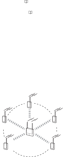
●In the infrastructure mode
When the network is configured in the infrastructure mode, we recommend
installing the wireless LAN stations within a radius of 20 m of the Wireless LAN
Access Point NE-W01E at their center as shown in the figure below.
(The standard distance for indoor communications is roughly 40 m.)
NE-W01E
NE-W11E
NE-W11E
NE-W11E
NE-W11E
NE-W11E
*We recommend limiting the number of devices connected to the access point
to eight devices.
16
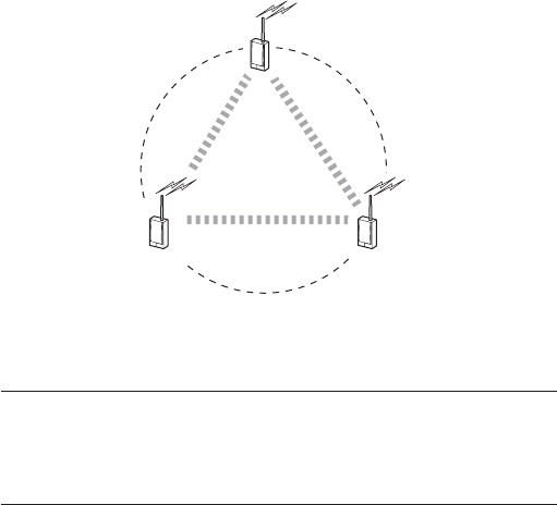
●In the ad-hoc mode
When the network is configured in the ad-hoc mode, we recommend installing
the wireless LAN stations so that they are within xxm of each other as shown in
the figure below. (The standard distance for indoor communications is roughly
40 m.)
*We recommend limiting the number of devices connected in this configura-
tion to three devices.
Note: When wireless LAN devices are installed too far away from each other or
there are obstacles that hinder wireless communications, communications
may not be possible between those wireless LAN devices. This is called the
"hidden terminal problem." In the ad-hoc mode, this may cause a drop in
throughput.
●Distance between surrounding areas
Be sure to allow at least 30 mm of space between the NE-W11E and other devices
or surrounding walls when installing the NE-W11E.
NE-W11E
NE-W11E
NE-W11E
17
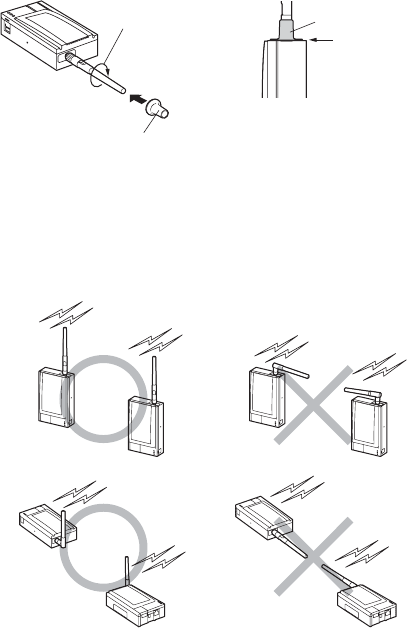
■Attaching the antennas
1Attach the rubber caps onto the antennas (provided).
2Adjust the orientation of the antennas.
Adjust the orientation of the antennas of each wireless LAN device so that
the antennas are parallel with each other. To adjust the orientation, turn the
antennas in the clockwise direction.
(1) Turn antenna in direction of
arrow to fasten.
(2) Insert rubber cap onto antenna
down to its base.
Rubber cap
Turn until cap fits flush.
18
CAUTION
■Installing the NE-W11E
The NE-W11E can be installed on flat surfaces such as desktops, on vertical
surfaces such as walls, and on ceilings. Select the mounting method according
to the environment where you will be using NE-W11E:
•Magnet mount
•Screw mount
•Wall mount
●Magnet mount
Mount the NE-W11E by the magnets on the back of the NE-W11E. This mounting
method is advantageous as it allows the NE-W11E to be fastened on horizontal
surfaces such as desktops, and vertical and slanted surfaces, and moved as you
like.
•When mounting the NE-W11E by the magnets, avoid using the NE-
W11E at locations subject to lots of vibration.
•Do not attach the magnets near products such as floppy disks that
are likely to be affected by magnetism.
• Sliding the body while it is attached to a steel desk or control panel
by the magnets may scratch painted surfaces.
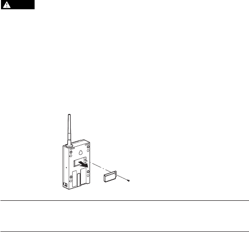
●Screw mount
1Unscrew the magnets on the rear of the NE-W11E body.
(1) Unscrew magnets.
(2) Remove magnets from body.
Note: When re-attaching the magnets after you have removed them from the NE-
W11E body, tighten the screws that hold the magnets in place with a torque
of 0.4 Nm {4 kgf•cm}.
19
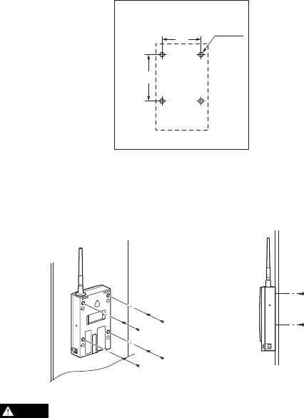
2Check the positions of the four screw holes, and drill holes for screw
fastening at the location (panel, etc.) where the NE-W11E body is to be
installed.
3Align the position of the screw-fastening holes with the rear of the NE-
W11E body, and fasten the four locations with the screws.
Tighten the screws with a torque of 0.4 Nm {4 kgf•cm}.
The depth of the screws provided with the NE-W11E is 5 mm. Use
screws of a length that takes into consideration the thickness of the
installation location (panel, etc.). Long screws might damage the NE-
W11E body.
CAUTION
66 ø3.5
(Installation location)
Unit: mm
+0.5
0
71
(view of NE-W11E from side)
(1) Fasten NE-W11E with
screws at four locations
from rear of body.
20
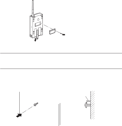
●Wall mount
1Remove the magnets on the rear of the NE-W11E body. Slide the wall-
mounting fixture downwards.
Note: When re-attaching the magnets after you have removed them from the NE-
W11E body, tighten the screws that hold the magnets in place with a torque
of 0.4 Nm {4 kgf•cm}.
2Attach two of the wall-mounting screws (provided) at the location (wall,
etc.) where the NE-W11E is to be installed.
(1) Unscrew magnets.
(2) Remove magnets from body.
(3) Slide wall-mounting fixture downwards.
(Location (wall, etc.) where
NE-W11E is to be installed)
(1) Attach wall-mounting
screws.
2.8 to 3.0 mm
(view of NE-W11E from side)

21
3Align and hook the screw holes on the rear of the NE-W11E body onto the
screws on the wall. Slide the body slightly downwards to prevent it from
falling from the wall.
4Attach the remaining wall-mounting screw in the hole of the mounting
fixture at the bottom of the NE-W11E body, and fasten the body firmly
against the wall.
(view of NE-W11 from side)
(1) Hook screw holes on
rear of NE-W11 body
onto screws on wall.
(1) Attach wall-mounting screws to fasten body
against wall.
22
Power Connection and Ground
Power can be supplied from the terminal in the power supply terminal block, and
also from the Ethernet port by the Power Over Ethernet (PoE) function.
"Power Over Ethernet (PoE)" (page 24)
The NE-W11E is not provided with a power switch. Note that the NE-W11E will start
operating once power is supplied to the NE-W11E from the power terminal block
or by the Power Over Ethernet (PoE) function.
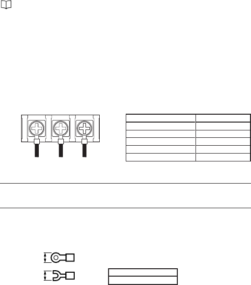
■Power terminal diagram
The power terminal is located inside the power terminal block when the cover
is opened. Open the cover upwards by hooking your finger on the claw on the
cover.
●Terminal specifications
Note: •Do not remove the power terminal with the NE-W11E power ON.
• Be sure to close the power terminal cover before use.
■When using crimped terminals
Use crimped terminals that conform to the following shapes and dimension.
NE-W11E
a: 6 mm max.
a
a
Description
AWG28-18
0.6 Nm {6 kgf•cm}
Copper
Stranded
+60°C/+75°C
Item
Wire size
Tightening torque
Wire material
Wire type
Rated lead temperature
Use three M3 screws.
+24V GND F.G.
Functional earth
23
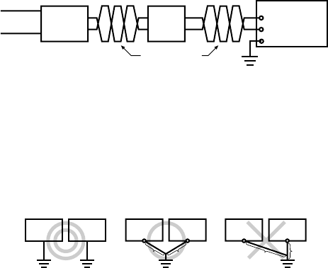
■Wiring
Connect the 24 VDC (10% power supply to the power supply input terminal as
follows:
■Grounding precautions
The following describes the precautions to follow when grounding the NE-
W11E.
•When grounding the ground terminal, use an exclusive earth. Also, provide
a Class D earth (Class III ground) and limit the grounding resistance to 100Ω
when performing grounding work.
•If an exclusive ground cannot be obtained, share the ground with another
device.
•Keep the grounding point as close as possible to the NE-W11E, and keep the
ground lead as short as possible.
•If the ground lead must be extended, use thick insulating lead, and pass the
lead through a duct before grounding.
Power supply
Twist these leads.
24 VDC±10%
Noise filter
NE-W11E body
Functional earthing
NE-W11E
body Other
device NE-W11E
body Other
device
Class D earth
Max. resistance of 100ΩClass D earth
Max. resistance of 100Ω
AB
A=B
NE-W11E
body Other
device
AB
A>B
A<B
24
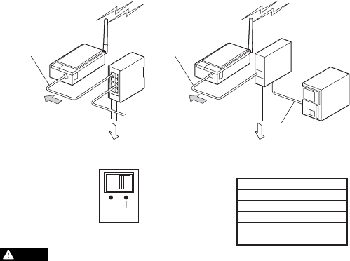
Power Over Ethernet (PoE)
The NE-W11E's Power Over Ethernet (PoE) function supplies power to the NE-W11E
from the Keyence Corporation Ethernet Switch NE-V08 or Data Storage Terminal
DT-100 via the STP cable* provided. By this function, power need not be connected
to the terminal block as power is supplied from the Ethernet port.
To use the PoE function, set the power selector switch on the bottom of the body to
"PoE". When the NE-W11E is connected to the NE-V08 or the DT-100, do not connect
to other network devices such as a hub in between by the Keyence Corporation STP
cable.
[Tip] For details on the PoE function on the power supplying side NE-V08 or DT-
100, refer to the various manuals or instruction manuals for the respective
product.
•Use the PoE function of the NE-W11E only on devices made by
Keyence Corporation that incorporate this function.
•Power supply from the power terminal block cannot be used at the
same time as the Power Over Ethernet (PoE) function.
•When the NE-W11E is connected to a device made by Keyence
Corporation that incorporates this function using the Keyence
Corporation STP cable, do not connect other network devices such
as a hub in between.
*
Keyence Corporation STP Cable
OP-51504 (0.2 m)
OP-51505 (0.5 m)
OP-51506 (1 m)
OP-51507 (3 m)
OP-51508 (5 m)
CAUTION
DT-100
Other
manufacturer's
PLC
Other communi-
cations device
(without PoE function)
NE-W11E NE-V08
Keyence STP cable
RS-232C/422 cable
Keyence STP cable
Power is supplied to
NE-W11E by PoE
function.
Power is supplied to
NE-W11E by PoE
function.
Connect to 24 VDC power supply.
NE-W11E
Connect to 24 VDC power supply.
EXT PoE
Set power selector switch to "PoE side".
(Default setting is "EXT".)

25
Inspection Standard
Voltage fluctuation must be within the allowable range.
24 VDC±10%
Must be within the operating ambient temperature range.
0 to +50°C
Must be within the operating ambient humidity range.
Max. 80%RH
Dirt or dust is not allowed to accumulate.
The connector must be completely inserted and must not be
loose.
The LAN cable must free from abnormalities such as broken
leads.
The power terminal block, antenna and mounting screws must
not be loose.
Inspection Item
Power supply
Ambient environ-
ment conditions
Mounting condi-
tions
Voltage fluctuations on power
terminal
Ambient temperature
Ambient humidity
Dust, dirt, etc.
State of LAN cables
LAN cable connections
Loose screws
Periodic Maintenance and Inspection
■Maintenance
•Inspect the NE-W11E once every six months to one year. Inspect the NE-
W11E at shorter inspection periods if it is used in extremely high-temperature
and/or high-humidity or dusty environments.
•If you cannot remove dirt or dust on the NE-W11E by wiping with a soft, dry
cloth, wipe with a firmly wrung cloth moistened with watered down neutral
detergent.
•If rubber, vinyl products or adhesive tape are left attached to the NE-W11E for
a long period of time, the NE-W11E may become stained. Remove any of these
during cleaning if attached to the NE-W11E.
Precautions When Replacing the Body
Pay attention to the following points when replacing the body:
•Turn the power OFF before you replace the body.
•After replacing the body, check the new body for any abnormalities.
•If a nonconformity necessitates that the body be repaired, send the body back to
your Keyence agent attached with a sheet of paper described the circumstances
in which the nonconformity occurred in as much detail as possible.

26
Troubleshooting
●The POWER LED does not light.
•Make sure that the power terminal is connected correctly to the power supply
terminal block.
•Make sure that the power supply method (terminal block or Power Over
Ethernet) and the power selector switch on the NE-W11E are correctly set.
•Swap the power supply with a different power supply and check again.
●The WIRELESS LED does not light.
•When the Wireless LAN Access Point NE-W01E is used, make sure that the
access point is ON.
•Make sure that ESS ID and other wireless LAN connection settings match
those of the other party NE-W01E is communicating with over the wireless
LAN.
●The ETHERNET LED does not light.
•Make sure that the cables are firmly inserted.
•Try switching the straight/cross selector switch to see if the ETHERNET LED
lights.
• Make sure that the devices that are connected to the Ethernet port are ON.
•Make sure that the cable connected to the Ethernet port is a cable of the correct
type.
•Check the cables for any breaks using a cable tester or similar device.
●Cannot use the Power Over Ethernet function.
•Check whether or not the connection destination device supports the Keyence
Corporation Power Over Ethernet function.
•Make sure that the power selector switch on the side of the NE-W11E is set
to "PoE". Also, make sure that the PoE function on the supplying side NE-V08
or DT-100 is set correctly.
For details on the PoE function on the power supplying side device, refer to
the various manuals or instruction manuals for the respective product.
•Make sure that cables currently used for connection support the Keyence
Corporation Power Over Ethernet function.
For details on Keyence Corporation cables that can be used, see "Power Over
Ethernet (PoE)" ( page 24).
27
Specifications
■General specifications
■Functional and performance specifications
*1 The terminal block and the RJ-45 terminal (PoE function) cannot be used at the same time. Switch the power
input by the power selector switch on the bottom of the body before use.
*2 STP/UTP (Category 3 or higher) compatible
Item
Power input
Communications port
Antenna
Power selector switch
Initialize switch
Structure
NE-W11E
Terminal block (3P: 24 V, GND, F.G.)/RJ-45 terminal (pin No.7: 24 V, pin No.8:
GND)*1
Wired: 10Base-T (MDI/MDI-X procedure selection)*2
Wireless: IEEE802.11b
1
"EXT" (terminal block)/"PoE" (RJ-45): Power input selection
This switch is used to return setting values to their defaults (factory settings).
Magnet mount
Screw mount
Wall mount
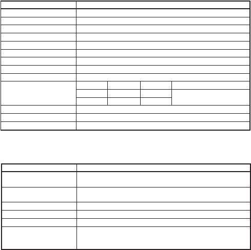
Item
Power supply voltage
Current consumption
Overvoltage category
Ground
Operating ambient temperature
Storage temperature
Operating ambient humidity
Storage humidity
Pollution degree
Vibration resistance
Ambient atmosphere
Weight
Applicable standards
NE-W11E
24 VDC±10%
100 mA max.
I
Class D earth (max. resistance of 100 Ω)
0 to +50°C (freezing not allowed)
-20 to +70°C
35 to 80%RH (condensation not allowed)
35 to 80%RH (condensation not allowed)
2
Frequency Acceleration Amplitude Number of sweeps
10 to 57 Hz — 0.075 mm
57 to 150 Hz 9.8 m/s2—
Excessive dirt, dust or corrosive gas not allowed
Approx. 310 g
CE, UL, FCC, Wireless Telegraphy Act
10 times in each of X, Y and Z
directions (for 80 minutes)
28
Item NE-W11E
Compliant standard IEEE802.3
Baud rate 10 Mbps
Transmission medium STP/UTP (Category 3 or higher)
■Wireless LAN specifications
*1 Eight or less units (infrastructure mode) or three or less (ad-hoc mode) units are recommended.
*2 Transmission distance is a logical value. The actual transmission distance varies according to the environment
you are operating in.
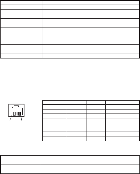
■Ethernet port I/O specifications
Pin assignment table (Ethernet)
RD: Receive data TD: Send data
Item
Data transmission rate
Network standard
Frequency band
Network architecture
Transmission system
Modulation system
Number of connection channels
Transmission distance*2
Encryption
NE-W11E
1/2/5.5/11 Mbps (automatically selected)
IEEE802.11b
2.4 GHz
Infrastructure/ad-hoc mode*1
DS-SS (Direct Sequence Spread Spectrum)
DBPSK (at 1 Mbps)
DQPSK (at 2 Mbps)
CCK (at 5.5/11 Mbps)
11
Open areas: Approx. 200 m
Indoors: Approx. 40 m
WEP 64/128 bit
(1)(8)
RJ-45 modular connector
* View from outside of NE-W11E
Pin No. MDI MDI-X PoE
1TD+ RD+ –
2TD– RD– –
3RD+ TD+ –
4–– –
5–– –
6RD– TD– –
7––+24 VDC when PoE is ON
8––GND when PoE is ON

29
■Defaults (factory settings)
These are the settings that are set on the NE-W11E before it is shipped from the
factory.
■MAC addresses
A "MAC address" is a unique address that is assigned to each individual device,
and comprises six bytes or 48 bits. MAC addresses cannot be changed by the
user as they are programmed to the NE-W11E. The MAC address programmed
to the NE-W11E is written on the product label on the side of the body.
Item Setting Value
Unit name NE-W11E
Password None
IP setting mode Fixed
IP address 192.168.0.14
Subnet mask 255.255.255.0
Gateway address 0.0.0.0
Communications mode Infrastructure
ESSID KeyenceWLAN
Channel 1
Encryption (WEP) OFF
30
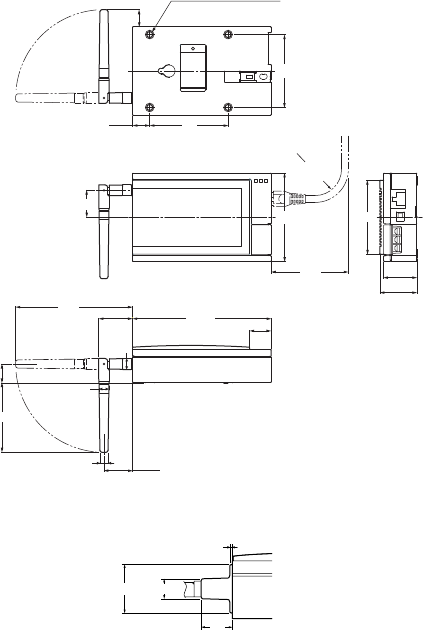
4-M3 (mounting screws)
Eff. screw depth 5 mm
ø10
15.6
66
67
33.8
30.2
80
(70)
24.4
106
19.5
25.9
ø8.7
ø7.4
15.5 71
125.5
30.7
63
17
Min. bending radius 24 mm
(R24)
✽
✽ When Keyence STP cable is used
ø24 (ø12)
1.2
19
Unit: mm
External Dimensions
■Expanded view when rubber caps are attached
31
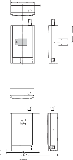
22.6
20.6
0.4 (magnet clearance)
54.7
25.125.5 29.4
(front perspective)
ø5 (mounting hole)
51
10
9.5 5
7.5
25.5
105
(front perspective)
■Magnet mounting diagram
■Wall mounting diagram
32

33
Warranty
1. Warranty Period
The warranty period for this product shall be one year from the date of purchase
at the specified location.
2. Scope of Warranty
(1) If a malfunction due the liability on the part of KEYENCE CORPORATION arises
during the above warranty period, this product shall be repaired free of charge.
However, instances that fall under the following categories shall be excluded
from the scope of warranty:
(1) Malfunctions due to inappropriate conditions, environment, handling, and
method of use other than described in the operation manual, user's manual,
and other separately exchanged specifications, etc.
(2) Malfunctions due to a cause other than a KEYENCE CORPORATION product
such as a customer's device or software design
(3) Malfunctions due to remodeling and repair other than KEYENCE CORPORA-
TION
(4) Malfunctions recognized as being preventable if consumables listed in the
operation manual and user's manual, for example, are maintained and
replaced correctly
(5) Malfunctions due to unforeseen causes in scientific and technical standards
before shipment
(6) Other malfunctions due to fire, earthquake, water damage, and other
disasters, and external factors such as abnormal power voltage that are not
the liability of KEYENCE CORPORATION
(2) (1) above shall be set as the restriction for the scope of warranty, and secondary
damages (damage to devices, mechanical loss, profit due to defects, etc.) on the
part of the customer due to malfunction of a KEYENCE CORPORATION product
and any other damages whatsoever shall be outside the scope of warranty.
3. Scope of Application of This Product
KEYENCE CORPORATION products are designed and manufactured as general-
purpose equipment for general industrial applications. Use in applications such
as nuclear power generation, aircraft, railways, and medical equipment, for
example, where excessive influence is expected on human life and property shall
be outside of the scope of application of this product. Note, however, that use
of this product in applications where the user has understood the specifications
of this product after prior consultation with KEYENCE CORPORATION shall be
within the scope of application of this product. (Even in this instance, the scope
of application of this warranty shall be the same as described above.)

34
KEYENCE CORPORATION
1-3-14, Higashi-Nakajima, Higashi-Yodogawa-ku,
Osaka, 533-8555, Japan
PHONE: +81-6-6379-2211 FAX: +81-6-6379-2131
©KEYENCE CORPORATION, 2003 0103-2 96M1069 Printed in Japan