Keysight Technologies Malaysia Sdn Bhd U1115A Remote Logging Display User Manual U1115 90103
Keysight Technologies Malaysia Sdn. Bhd. Remote Logging Display U1115 90103
UserManual.wiki
>
Keysight Technologies Malaysia Sdn Bhd
>
U1115A User Manual
User Manual
Navigation menu
Upload a User Manual
Namespaces
Wiki Guide
HTML
PDF
Info
Views
User Manual
Discussion / Help
Navigation
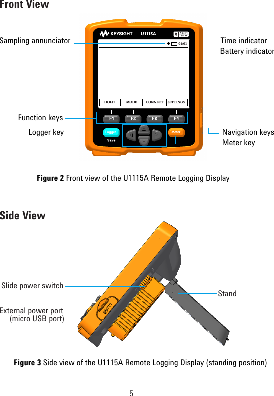
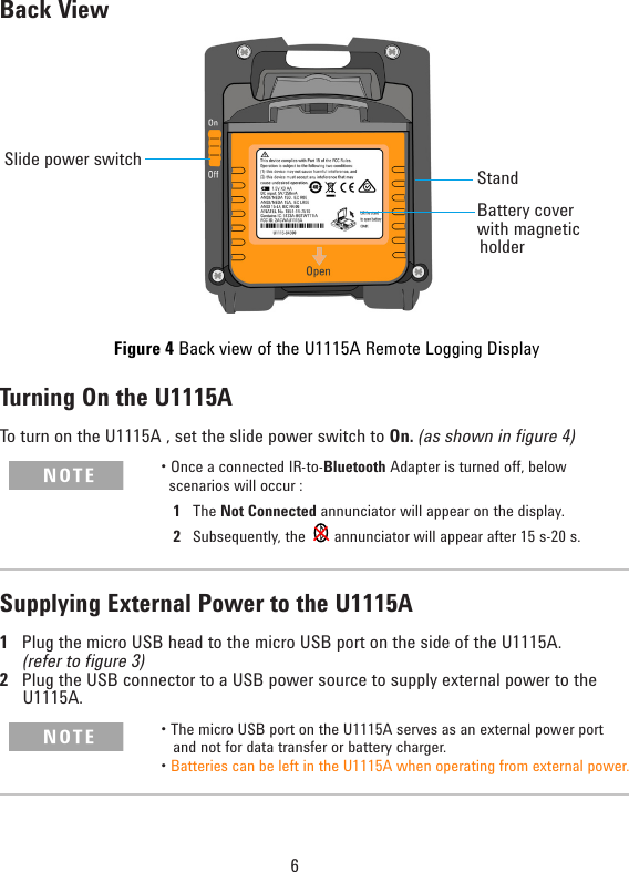
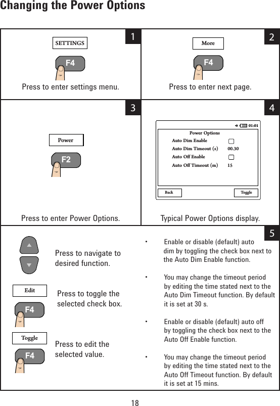
![17Changing the Display SettingsPress to enter settings menu. Press to enter display menu.PresstoselectOutdoordisplay.(TypicalOutdoordisplayasshownhere)Press to select Indoor display.(Typical Indoor display as shown here)Press to increase or decrease the display brightness from lowest [Backlight(1)]tohighest[Backlight(7)].ThedefaultisBacklight(3).SETTINGS DisplayU1273A-MY51430008 U1272A-MY52800017B> U1177A-2718DEU1252B-MY51040033C> U1117A-2391BA Not ConnectedA> U1117A-57AE5BONBacklight(6)Back Outdoor Indoor01:01U1273A-MY51430008 U1272A-MY52800017B> U1177A-2718DEU1252B-MY51040033C> U1117A-2391BA Not ConnectedA> U1117A-57AE5BU1273A-MY51430008 U1272A-MY52800017B> U1177A-2718DEU1252B-MY51040033C> U1117A-2391BA Not ConnectedA> U1117A-57AE5B123 45F4 F3F3 F4F2](https://usermanual.wiki/Keysight-Technologies-Malaysia-Sdn-Bhd/U1115A/User-Guide-2621690-Page-17.png)