Keysight Technologies Malaysia Sdn Bhd U1115A Remote Logging Display User Manual U1115 90103
Keysight Technologies Malaysia Sdn. Bhd. Remote Logging Display U1115 90103
User Manual
1
Keysight U1115A Remote Logging Display
Operating Instructions
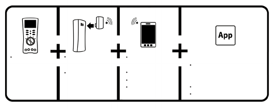
The Keysight U1115A Remote Logging display is designed to be used with the
Keysight U1200 Series handheld meters, Keysight U1117A IR-to-Bluetooth®1
Adapter, Keysight U1177A IR-to-Bluetooth Adapter and mobile/software2
applications to provide you a total wireless remote connectivity solution.
With the U1115A, you can view readings from up to four handheld meters
simultaneously, from an extended distance of up to 100-metres (U1117A) within
the line-of-sight.
Figure 1 Keysight wireless remote connectivity solution
Standard Shipped Items Checklist
The following items are included with your purchase:
• U1115ARemoteLoggingDisplay.
• Three1.5VAAbatteries.
• USBtomicroUSBcable(forexternalpoweronly).
• OperatingInstructions(thisbooklet).
• SoftCarryingCase.
1 The Bluetooth® word mark and logos are registered trademark owned by Bluetooth SIG, Inc and any
use of such marks by Keysight is under license. Other trademark and trade names are those of their
respective owners.
2 The Keysight U1115A only supports Keysight Handheld Meter Logger software for downloading logged data
to PC via Bluetooth connection.
Keysight U1200
Series handheld
meters
U1115A remote
logging display
WindowsPC
Android devices
iOSdevices
U1117A IR-to-
Bluetooth adapter
U1177A IR-to-
Bluetooth adapter
KeysightPCApplicationSoftware2
Keysight Handheld Meter
Logger
Keysight Mobile Application2
Keysight Mobile Meter
Keysight Mobile Logger

2
Product Characteristics
Temperature Operating condition:–20°Cto55°C
Storage condition:–40°Cto70°C
Relative Humidity (R.H) Operating condition:Upto80%at40°C(non-condensing)
Storage condition: Upto95%at40°C(non-condensing)
Dimension (W x L x H) 92.0 mm × 107.9 mm × 33.5 mm
Weight 238 g with batteries , 170 g without batteries.
Battery Type •CarbonZinc15D(ANSI/NEDA)andR6(IEC)
•Alkaline15A(ANSI/NEDA)andLR6(IEC)
•Lithium15LF(ANSI/NEDA)andFR6(IEC)
Battery Lifespan •Lithium batteries: 30 hours
•Alkalinebatteries:20hours
Power Consumption Maximum1VAfor3AAbatteries
Maximum5V+10%,250mAforexternalpower
AutoPowerOffmode,currentconsumption3mA
Warranty Oneyear(Doesnotcovernormalwearandtearof
mechanical parts and batteries)
Bluetooth BluetoothSPPprole,Class1device
Compatibility Keysight Handheld Meter/Display:
•KeysightU1200SeriesHandheldMeters
•KeysightU1117AIR-to-Bluetooth Adapter
•KeysightU1177AIR-to-Bluetooth Adapter
Keysight Application Software:
•KeysightHandheldMeterLogger
Hardware Device:
•WindowsPC(withBluetooth-enabled)
Regulatory The U1115A complies with the requirements of the
following product standards:
•EMCEN301489–1:V1.9.2
EN301489–17:V2.2.1
EN55022:2010(Group1ClassA)
EN55024:2010
•RF(Bluetooth)EN300328V1.7.1
•RF(Health)EN62311:2008
•Safety EN60950–1:2006+A11:2009
+A1:2010+A12:2011
Complieswith
IDAStandards
(DA106994)

3
Regulatory •IndiaEquipmentTypeApproval(ETA)CerticateNo:
NER-ETA/924
“This telecommunication equipment conforms to the
NTCtechnicalrequirement”
Table 1Connectivitydistance(approximate)withintheline-of-sight
U1177A U1117A U1115A
U1177A – – 10 m
U1117A – – 100 m
U1115A 10 m 100 m –
Other Class 1 devices 10 m 100 m 100 m
Other Class 2 devices 10 m 10 m 10 m

4
•CanadaIC:ThedevicecontainstransmitterIC:5123A–BGTWT11IA
•TocomplywithFCCandIndustryCanadaRFradiationexposurelimitsfor
general population, the antenna(s) used for this transmitter must be
installed such that a minimum separation distance of 20 cm is maintained
between the radiator (antenna) and all persons at all times and must not be
colocated or operating in conjunction with any other antenna or transmitter.
•“La operación de este equipo está sujeta a las siguientes dos condiciones:
(1) es posible que este equipo o dispositivo no cause interferencia
perjudicial y (2) este equipo o dispositivo debe aceptar cualquier
interferencia,incluyendolaquepuedacausarsuoperaciónnodeseada.”
•TheradiomodulecertiedbyJapaneseRadioLawisintegratedinside.
•NCCWarningStatement:
•Article12
Withoutpermission,anycompany,rmorusershallnotalterthe
frequency, increase the power, or change the characteristics and
functionsoftheoriginaldesignofthecertiedlowerpowerfrequency
electric machinery.
•Article14
The application of low power frequency electric machineries shall not
affect the navigation safety nor interfere a legal communication, if an
interference is found, the service will be suspended until improvement is
made and the interference no longer exists.
•AccordingtoFCCpart15.21:
Changesormodicationsnotexpresslyapprovedbythemanufacturerfor
compliance may void the user’s authority to operate the equipment.
•AccordingtoFCCpart15.105(b):
This equipment has been tested and found to comply with the limits for a
ClassBdigitaldevice,pursuanttopart15oftheFCCRules.Theselimitsare
designed to provide reasonable protection against harmful interference in
a residential installation. This equipment generates, uses, and can radiate
radio frequency energy, and if not installed and used in accoradance with
the instructions, may cause harmful interference to radio communications.
However,thereisnoguaranteethatinterferencewillnotoccurinaparticular
installation. If this equipment does cause harmful interference to radio or tele-
vision reception, which can be determined by turning the equipment off and
on, the user is encouraged to try to correct the interference by one or more of
the following measures:
•Reorient or relocate the receiving antenna.
•Increase the separation between the equipment and receiver.
•Connecttheequipmentintoanoutletonacircuitdifferentfromthatto
which the receiver is connected.
•Consultthedealeroranexperiencedradio/TVtechnicianforhelp.
•AccordingtoFCC15.19:
Thisdevicecomplieswithpart15oftheFCCrules.Operationissubjecttothe
following two conditions:
•This device may not cause harmful interference.
•This device must accept any interference received, including interfer-
ence that may cause undesired operation.
5
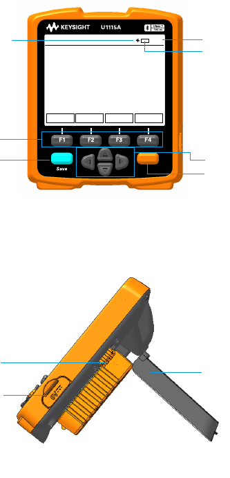
Front View
Sampling annunciator Time indicator
Batteryindicator
F3key
Functionkeys
LoggerkeyNavigationkeys
Meterkey
Figure 2FrontviewoftheU1115ARemoteLoggingDisplay
Side View
Slide power switch
Stand
Externalpowerport
(microUSBport)
Figure 3SideviewoftheU1115ARemoteLoggingDisplay(standingposition)
HOLD MODE CONNECT SETTINGS
01:01
Meter
Logger
6
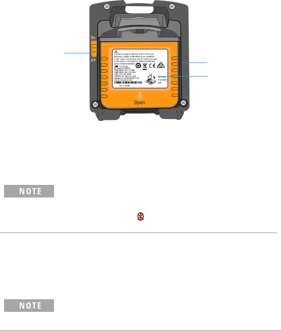
Back View
Slide power switch
Stand
Batterycover
with magnetic
holder
Figure 4BackviewoftheU1115ARemoteLoggingDisplay
Turning On the U1115A
To turn on the U1115A , set the slide power switch to On. (as shown in gure 4)
•OnceaconnectedIR-to-Bluetooth Adapter is turned off, below
scenarios will occur :
1 The Not Connected annunciator will appear on the display.
2 Subsequently, the annunciator will appear after 15 s-20 s.
Supplying External Power to the U1115A
1PlugthemicroUSBheadtothemicroUSBportonthesideoftheU1115A.
(refer to gure 3)
2PlugtheUSBconnectortoaUSBpowersourcetosupplyexternalpowertothe
U1115A.
•ThemicroUSBportontheU1115Aservesasanexternalpowerport
and not for data transfer or battery charger.
• BatteriescanbeleftintheU1115Awhenoperatingfromexternalpower.
7
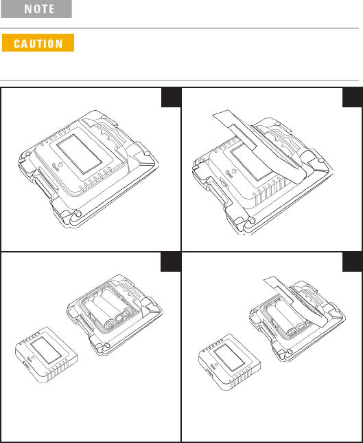
Installing and Replacing the Batteries
MakesureyouturnofftheU1115Abeforeinstallingorreplacingthe
batteries.
ToavoidtheU1115Abeingdamagedfrombatteryleakage:
• Always remove dead batteries immediately.
• Always remove the batteries and store them separately if the
U1115A is not going to be used for a long period of time.
Remove the battery protective sheet
beforeusingforthersttime.
1 2
3 4
8
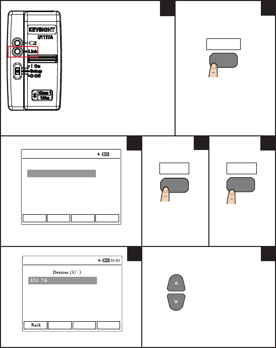
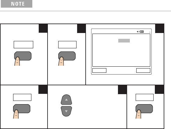
Connecting to Devices
EnsurethattheLinkLEDatthe
IR-to-Bluetooth adapter
isblinkingbeforeestablishinga
connection.
Power cycle if necessary.
FrontviewoftheU1117A
IR-to-Bluetooth adapter
PresstoenterConnection
Manager. (U1115A)
TypicalConnectionManagerdisplay.
Press to add
devices.
Press to scan for
devices.
TypicalAvailableDevicesdisplay.
Press to navigate to
desired device.
F3
CONNECT
Back
A> Add Device
B> Add Device
C> Add Device
D> Add Device
Bluetooth Enter
Connection Manager
01:01
F4
Enter
57AE5B
1
Scan Select
U1177A-2718DE
2
Available
12
345
6
Scan
F3
7
9
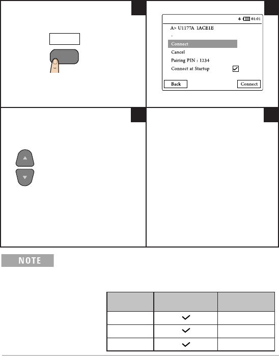
Connecting to Devices (continued)
Press to select the desired device. Typical connection menu display.
Press to navigate to desired
function.
• Select Connect tomakeaconnection.
• Select Cancel to cancel a connection.
• Select Pairing PIN : 1234 to change
PINnumber.EnsurethattheU1115A
and the IR-to-Bluetooth adapter(s)
havematchingPINnumber(s).
• Select Connect at Startup to set
thedevicetoconnectonstartup.By
selecting this option, it will determine
the number of views as shown in
Table 2 below.
8 9
10 11
Select
F4
ConnectionManagercanaddupto4devicesatanyonetime.
Meter view is automatically selected based on the table below :
Table 2 Meter view selection
Connected
devices Connect At Startup Meter view
1 1-meter view
2 2-meter view
3 or 4 4-meter view
10
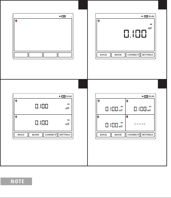
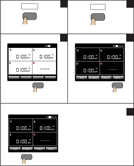
Meter View
Typical screen display when no meter is
connected to the U1115A.
Typical screen display when one meter
is connected to the U1115A.
Typical screen display when two meters
are connected to the U1115A.
Typical screen display when three
or four meters are connected to the
U1115A.
The U1115A screen display will show ----- when:
1Nometerisconnected.
2 Meter(s) function/mode is not supported by the U1115A.
3 When the user changes the meter’s function. Typical wait time is 5s.
01:01
HOLD MODE CONNECT SETTINGS
-- -- -
A> U1117A-57AE5B Not Connected A> U1273A-MY51430008U1117A-57AE5B
A> U1273A-MY51430008
B> U1177A-2718DE U1272A-MY52800017
U1117A-57AE5B
U1273A-MY51430008
A> U1272A-MY52800017
B> U1177A-2718DE
U1252B-MY51040033
C> U1117A-2391BA Not Connected
U1117A-57AE5B
1 2
3 4
11
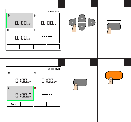
Identifying a Connected Meter
The identify meter function allows you to easily identify your connected meter(s).
To identify the connected meter, follow the steps below :
1 In the meter view, select the desired meter and press CONNECT.
2 Then, navigate to the desired connected device and press Identify.
3Themetercorrespondstotheselecteddevicewillbeepandashit’sbacklight.
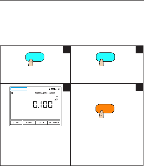
Selecting Measurement Mode
Typical meter view display.
Press to navigate
to the desired
meter.
Press to enter
mode menu.
Typical mode menu display.
The active window will be highlighted.
Press to select
desired mode. In
thisexample,ACV
is selected.
Press to exit mode
menu.
MODE
F2
U1273A-MY51430008 U1272A-MY52800017
B> U1177A-2718DE
U1252B-MY51040033
C> U1117A-2391BA Not Connected
A> U1117A-57AE5B
MODEHOLD CONNECT SETTINGS
123
4
Vac
F2
U1273A-MY51430008 U1272A-MY52800017
B> U1177A-2718DE
U1252B-MY51040033
C> U1117A-2391BA Not Connected
A> U1117A-57AE5B
Vac Vdc Vacdc
56
Meter
12
Performing Data Logging
The data logging function provides you the convenience of recording test data for
future review or analysis.
Table 3 Dataloggingmaximumcapacity
Data logging option Maximum storage capacity
Manual log 500 pts
Interval log 60000pts/100sessions1
1 For interval log, a maximum of 60 000 points or 100 sessions can be stored, whichever occurs rst.
Session ends when the U1115A powers off, count mode ends, restarts new logging or all connected meter(s)
disconnect
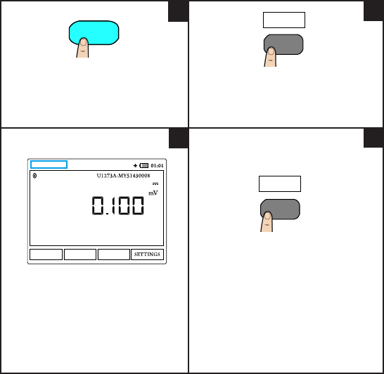
Performing Manual Logging
Press to enter data log mode.1
1Proceed to Step 2 if the U1115A is already in meter
view.
Press for >1 s to store the present value.
Typical manual log display.
Manual Logged : x1 is displayed at the
top left of the display once a value is
logged.
1 X denotes 1,2,3,4,...which represents the current
log count.
Press to exit data log mode.
Logger
Manual Logged : 1
A> U1117A-57AE5B
12
4
Meter
3
Logger
13
Performing Interval Logging
Press to enter data log menu. Press to start interval log mode.
Subsequent readings are automatically
recorded into the multimeter’s memory at
theintervalspeciedinthesetupmenu.
Typical interval log display.
LogCounts:x1 is displayed at the
top left of the display once a value is
logged.
1 X denotes 1,2,3,4,...which represents the current
log count.
Press to exit interval log mode.
START
STOP
Log Counts : 1
A> U1117A-57AE5B
STOP
12
4
3
Logger
F1
F1
14
Table 4 DataloggerSetupoptions
Option Available settings Description
Interval 1 s-10 mins Delaytimebetweensubsequent
readings.Bydefaultitissetat2s.
CountMode On/Off(default) Enableordisabletheintervaldata
log process to stop when the logged
data have reached count settings.
Count 1-60000 Total readings that need to be
logged.
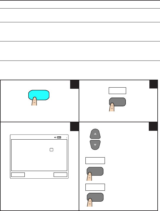
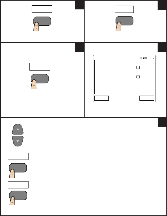
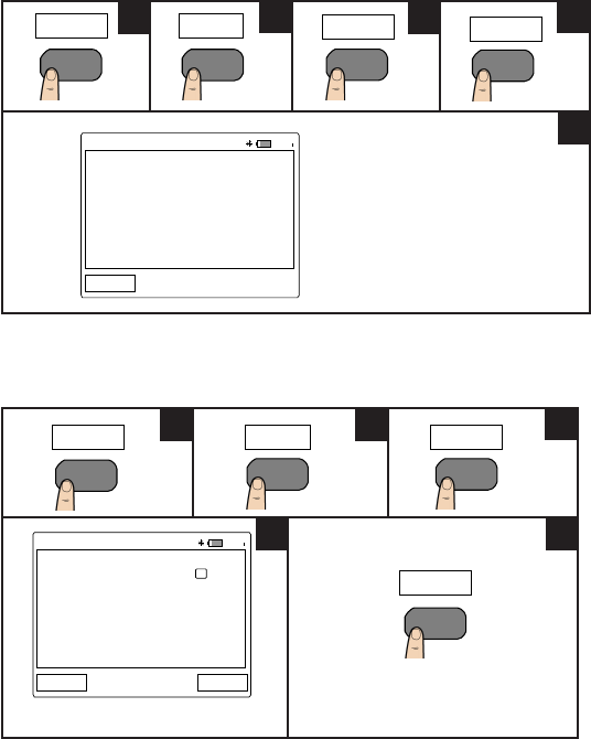
Changing Datalogger Setup Options
Press to enter data log mode. PresstoenterDataloggerSetupmenu.
TypicalDataloggerSetupmenudisplay.
Press to navigate to
desired function.
Press to edit the
selected value.
Press to toggle the
selectedcheckbox.
MENU
01:01
Datalogger Setup
Interval 00:02
Count Mode
Count 60000
Back Edit
Available Sessions : 100
Available Interval Counts : 60000
Available Manual Counts : 500
12
4
3
Logger
F2
Edit
F4
Toggle
F4
15
Reviewing Previously Recorded Data
Press to enter data log mode. Press to enter data menu.
Press to view the interval or manual
previously stored records. Typical Interval Log data display.
Typical Manual Log data display.
Press to navigate to
desired logged data.
Press to view the
selected data.
Freezing the Display (Hold)
To freeze the meters’ display(s), press HOLD. Press again to unhold.
Interval Manual
01:01
Interval Log (1/2)
25 Jan 2013 00:54:35 AM ( 4 pts)
Back Erase AllView
25 Jan 2013 00:54:05 AM ( 4 pts)
01:01
Manual Log (1/2)
Back Erase AllView
26 Jan 2013 00:54:35 AM
26 Jan 2013 00:54:05 AM
View
12
4
3
6
5
Logger DATA
F3
F3F2
F2
16
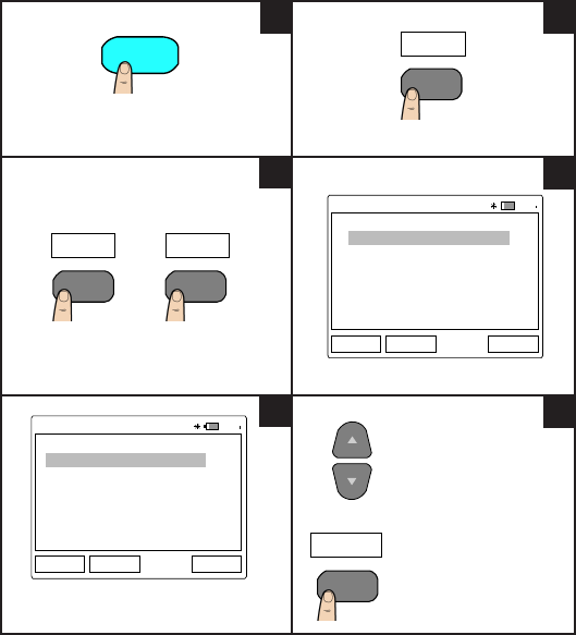
Connect the U1115A to PC via Bluetooth
Beforeyoubegin,makesuretheBluetooth connectiontoyourPCis
enabled.
1First,followthestepsbelowtosettheU1115Atoslavemode:
Press to enter
ConnectionManager.
Press to enter
BluetoothSetup. TypicalBluetoothSetupdisplay.
Press to edit Role.
Press to select Slave.
Press to save.
2FromyourPC(Windows7),gotostart > Devices and Printers.
3ClickAdd a device.
4 Select U1115A-XXXXXX1andclickNext.
5 Type the default Bluetoothpairingcode“1234”(default)andclick Next.
6Oncepairingissuccessful,anoticationwindowwillappear.ClickClose.
7 The U1115A-XXXXXXisnowaddedandsuccessfullyconnectedtoyourPC.
8Then,youcanconnecttheU1115AtotheKeysightHandheldMeterLoggersoftware
which is available at www.keysight.com/nd/hhmeterlogger
1 XXXXXX denotes the U1115A device name and can be obtained from the U1115A System Info (for more information,
refer to page 19).
CONNECT
F3
Bluetooth
F3
01:01
Bluetooth Setup
Role Master
Default PIN 1234
Back Edit
Edit
F4
OK
F4
12 3
456
17
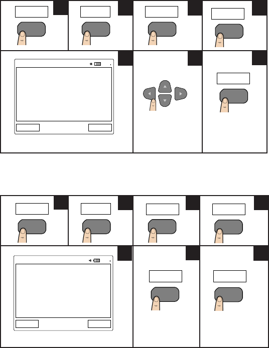
Changing the Display Settings
Press to enter settings menu. Press to enter display menu.
PresstoselectOutdoordisplay.
(TypicalOutdoordisplayasshownhere)
Press to select Indoor display.
(Typical Indoor display as shown here)
Press to increase or decrease the
display brightness from lowest
[Backlight(1)]tohighest[Backlight
(7)].
ThedefaultisBacklight(3).
SETTINGS Display
U1273A-MY51430008 U1272A-MY52800017
B> U1177A-2718DE
U1252B-MY51040033
C> U1117A-2391BA Not Connected
A> U1117A-57AE5B
ON
Backlight(6)Back Outdoor Indoor
01:01
U1273A-MY51430008 U1272A-MY52800017
B> U1177A-2718DE
U1252B-MY51040033
C> U1117A-2391BA Not Connected
A> U1117A-57AE5B
U1273A-MY51430008 U1272A-MY52800017
B> U1177A-2718DE
U1252B-MY51040033
C> U1117A-2391BA Not Connected
A> U1117A-57AE5B
12
3 4
5
F4 F3
F3 F4
F2
18
Changing the Power Options
Press to enter settings menu. Press to enter next page.
PresstoenterPowerOptions. TypicalPowerOptionsdisplay.
Press to navigate to
desired function.
Press to toggle the
selectedcheckbox.
Press to edit the
selected value.
• Enableordisable(default)auto
dimbytogglingthecheckboxnextto
theAutoDimEnablefunction.
• You may change the timeout period
by editing the time stated next to the
AutoDimTimeout function.Bydefault
it is set at 30 s.
• Enableordisable(default)autooff
bytogglingthecheckboxnexttothe
AutoOffEnablefunction.
• You may change the timeout period
by editing the time stated next to the
AutoOffTimeoutfunction.Bydefault
it is set at 15 mins.
More
Power
01:01
Power Options
Auto Dim Enable
Auto Dim Timeout (s) 00.30
Auto Off Enable
Auto Off Timeout (m) 15
Back Toggle
12
3 4
5
SETTINGS
F4 F4
F2
Edit
F4
Toggle
F4
19
Changing the Date and Time
TypicalDate/Timedisplay.
Press to navigate
to desired function.
Press to edit the
selected values.
Resetting the U1115A
Typical System Reset display.
Press to restore
the U1115A to
factory stage.
Press to cancel.
01:01
Date/Time
Date 21 June 2013
Time 00:29:24
Back Edit
SETTINGS
F4
More
F4
System
F3
Date/Time
F2
Edit
F4
123 4
567
SETTINGS
F4
More
F4
System
F3
Reset
F3
01:01
System Reset
Factory reset will erase all your
data and settings to restore the
U1115A back to factory stage.
Do you want to proceed?
No Yes
Yes
F4
No
F1
12 3 4
567
20
Viewing the System Info
Typical System Info display.
Enabling/Disabling the Beeper
Typical Utility display.
Togglethecheckboxtoenableor
disable the beeper.
Sys Info
01:01
System Info
Model U1115A
Serial MY51080009
Fw version 01.00
Device Name U1115A-6A1F81
Back
SETTINGS
F4
More
F4
System
F3 F4
01:01
Utility
Beeper
Back Toggle
SETTINGS
F4
More
F4
Utility
F4
Toggle
F4
1234
5
123
45

21
THISPAGEHASBEENINTENTIONALLYLEFTBLANK

22
THISPAGEHASBEENINTENTIONALLYLEFTBLANK

23
THISPAGEHASBEENINTENTIONALLYLEFTBLANK

24
©Keysight Technologies 2014
Printed in Malaysia
November2014
U1115-90103
Assistance
Fortechnicalassistance,contactyournearestKeysightSalesOfceorvisit
the Keysight website at www.keysight.com/nd/assist for further information.
Modelo U1115A
1851-14-7510
“Esteequipamentooperaemcaráter
secundário, isto é, não tem direito a proteção
contra interferência prejudicial, mesmo de
estações do mesmo tipo, e não pode causar
interferência a sistemas operando em caráter
primário.”
(01)07898956006039