Keystone Microtech KT-61205W Smart I/O+ Controller User Manual 05 KT 61205W Manual 0909x
Keystone Microtech Corporation Smart I/O+ Controller 05 KT 61205W Manual 0909x
User manual

SIO Plus Series Controller
User’s Manual
Version 1.0, Aug. 2015

KT‐612XXSIOPlusSeriesControllerUM2
KT‐61205/KT‐61205W/KT‐61220/KT‐61220W
SIOPlusSeriesController
User’sManual
CopyrightNotice
©2015KeystoneMicrotechCorporation.Allrightsreserved.
ImportantNote
RadiationExplosureStatement
ThisequipmentcomplieswithCE/FCCradiationexposurelimitssetforthfor
anuncontrolledenvironment.Thisequipmentshouldbeinstalledandoperated
withminimumdistance20cmbetweentheradiator&yourbody.
FCCInformation
Thisdevicecomplieswithpart15oftheFCCRules.Operationissubjectto
thefollowingtwoconditions:(1)Thisdevicemaynotcauseharmfulinterference,and
(2)thisdevicemustacceptanyinterferencereceived,includinginterferencethatmay
causeundesiredoperation.
Caution:
Anychangesormodificationsnotexpresslyapprovedbythepartyresponsible
forcompliancecouldvoidtheuser’sauthoritytooperatethisequipment.
Thisproductcontainsaradiotransmitterwithwirelesstechnologywhichhas
beentestedandfoundtobecompliantwiththeapplicableregulationsgoverninga
radiotransmitterinthe2.400GHzto2.483GHzfrequencyrange.

KT‐612XXSIOPlusSeriesControllerUM3
TheKT‐61205SIOPluscontrollerisastandaloneremoteIOcontrollerthatcan
connectsensorsandturnon/offrelaysorswitchesforapplicationoverEthernetand
IP‐basednetworks.
APLC‐likelogicprocessingengineisbuiltintheKT‐61205,sotheusercanprogram
thisdeviceforprocesscontrol,dataaquitisionorotherautomationapplication.
OneofthemostpowerfulfeatureoftheSIOPluscontrolleristhecapabilityto
connecttoacloudontheinternet,callK‐Cloudservice.TheK‐Cloudserviceprovides
theuseraninfrastructureforremotesensorreadingandoutputcontroloverthe
InternetwithoutthecomplexnetworksettingsoffirewallorVPN(virtualprivate
network).
Thisuser’smanualguidesyouthroughthefollowingstepstounderstandthebasic
operationoftheKT‐61205Smart‐IOcontrollers:
z Understandthehardware
z Installthehardware
z DownloadandinstallthePCSoftware
z ConfigureandmonitortheSmartIOcontrollerviathePCSoftware
z Writeandupdateanadvancedcontrolblock(ACB)programtotheSIOplus
controller
z UsetheK‐Cloudservice
KT‐612XXSIOPlusSeriesControllerUM4
1. Understandthehardware
Hardwaredescription:
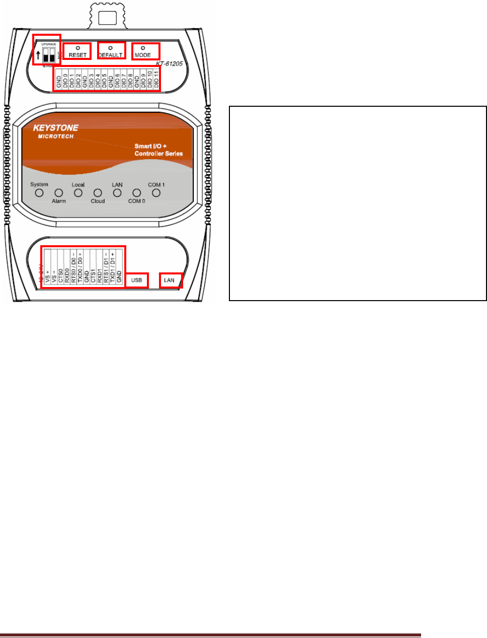
KT‐61205productoverview:
1
2
3
4
5
6
7
8
1.Normal/Setting:NormalModeorSettingMode
2.Reset:SystemResetPushButton.
3.Default:ResettoFactorydefaultsetting,notinclude
Modbussetting.
4.Mode:SwitchtoLocalModeorCloudMode.
5.TerminalBlock1:ForDC12~24Vpowerinputand
RS232/RS485signalconnection.
6.USB:USB2.0Pen‐drivepluginut.
7:LAN:EthernetRJ45cablepluginput.
8 : TerminalBlock2:DigitalInputandOutputTerminal.
KT‐612XXSIOPlusSeriesControllerUM5
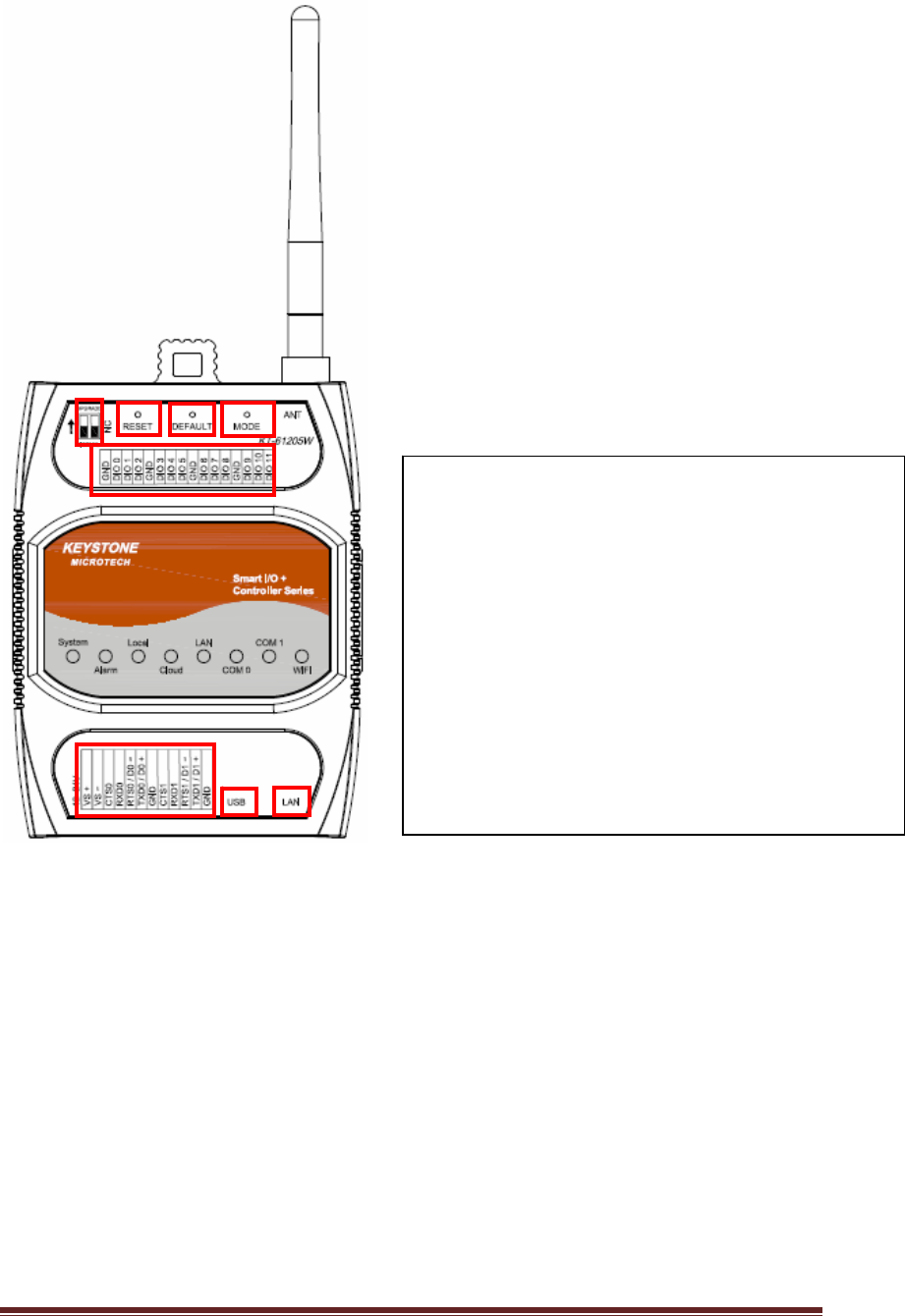
KT‐61205Wproductoverview:
1
2
3
4
5
6
7
8
1.Normal/Setting:NormalModeorSettingMode
2.Reset:SystemResetPushButton.
3.Default:ResettoFactorydefaultsetting,notinclude
Modbussetting.
4.Mode:SwitchtoLocalModeorCloudMode.
5.TerminalBlock1:ForDC12~24Vpowerinputand
RS232/RS485signalconnection.
6.USB:USB2.0Pen‐drivepluginut.
7:LAN:EthernetRJ45cablepluginput.
8 : TerminalBlock2:DigitalInputandOutputTerminal.
KT‐612XXSIOPlusSeriesControllerUM6
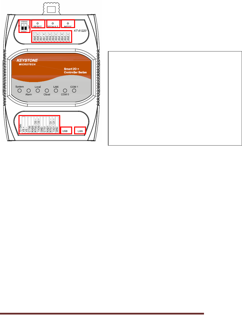
KT‐61220productoverview:
1
2
3
4
5
67
8
1.Normal/Setting:NormalModeorSettingMode
2.Reset:SystemResetPushButton.
3.Default:ResettoFactorydefaultsetting,notincludeModbus
setting.
4.Mode:SwitchtoLocalModeorCloudMode.
5.TerminalBlock1:ForDC12~24Vpowerinputand
RS232/RS485signalconnection.
6.USB:USB2.0Pen‐drivepluginut.
7:LAN:EthernetRJ45cablepluginput.
8 : TerminalBlock2:AnalogInput(Voltage/Current)Terminal.
KT‐612XXSIOPlusSeriesControllerUM7
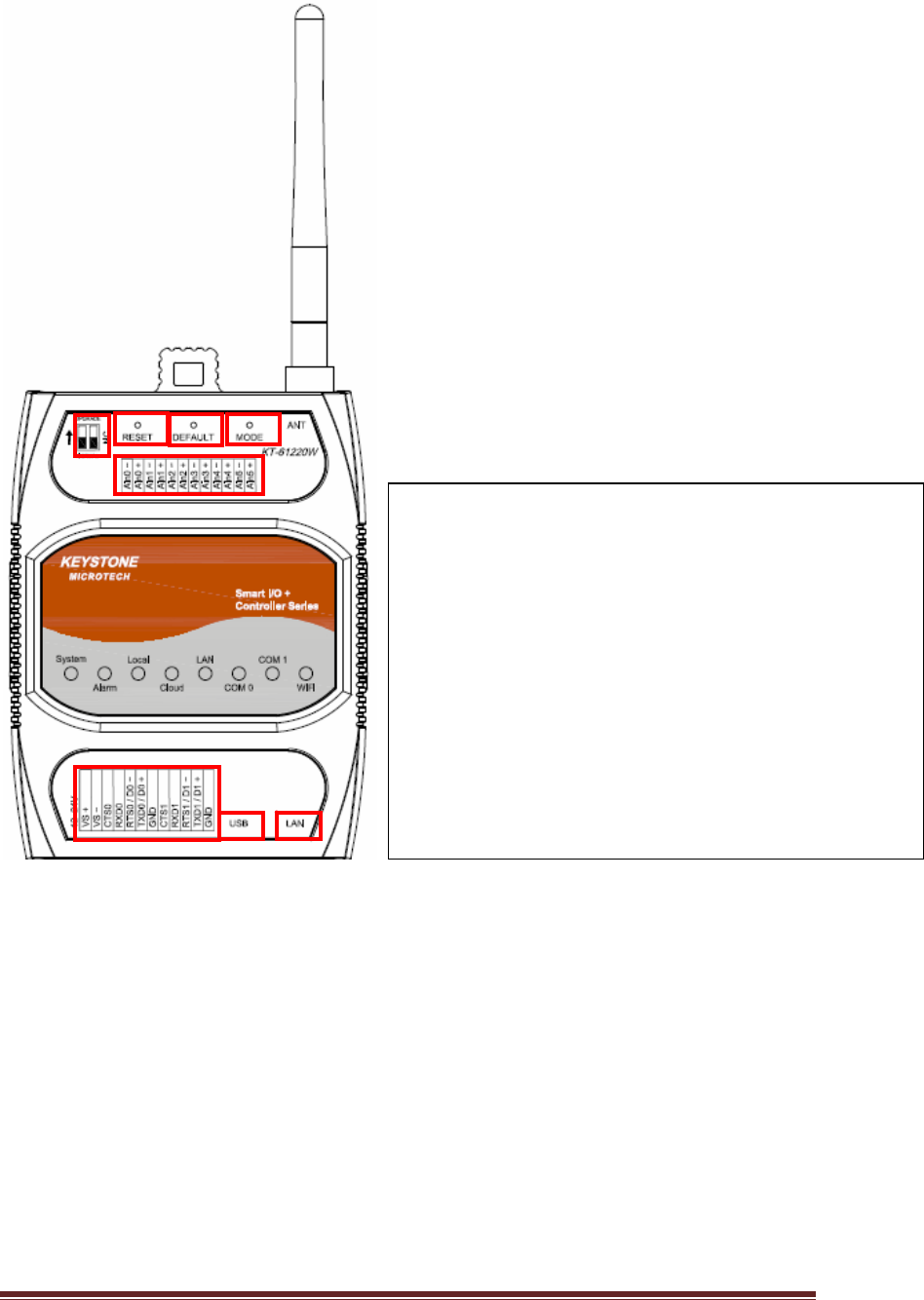
KT‐61220Wproductoverview:
1
2
3
4
5
6
7
8
1.Normal/Setting:NormalModeorSettingMode
2.Reset:SystemResetPushButton.
3.Default:ResettoFactorydefaultsetting,notincludeModbus
setting.
4.Mode:SwitchtoLocalModeorCloudMode.
5.TerminalBlock1:ForDC12~24Vpowerinputand
RS232/RS485signalconnection.
6.USB:USB2.0Pen‐drivepluginut.
7:LAN:EthernetRJ45cablepluginput.
8 : TerminalBlock2:AnalogInput(Voltage/Current)Terminal.

KT‐612XXSIOPlusSeriesControllerUM8
PanelGuide
I/OTerminal Block1:(KT‐61205/KT‐61205W/KT‐61220/KT‐61220W)
PinAssignDescription:
Signal PinDescription Specification
TXD0
RTS0
RXD0
CTS0
RS232UARTserialPort0 Maximumbaudrate:
115200bps
TXD0/D0+
RXD0/D0‐
2‐wireRS48UARTserialPort0 Maximumbaudrate:
921600bps
TXD1
RTS1
RXD1
CTS1
RS232UARTserialPort1 Maximumbaudrate:
115200bps
TXD1/D1+
RXD1/D1‐
2‐wireRS48UARTserialPort1 Maximumbaudrate:
921600bps
VS‐/VS+DCPowerInput +12V~+24V
USBUSB2.0Pen‐drivePlug SavedataintoUSBPen‐drive
GNDSignalGND
KT‐612XXSIOPlusSeriesControllerUM9
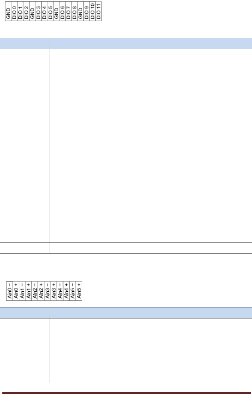
I/OTerminal Block2:(KT‐61205/KT‐61205W)
Signal PinDescription Specification
DIO0~DIO11DigitalInput/OutputPort S/WConfigurable
DigitalInput
Supprot:
Type:DryContact,
WetContact
(NPNType)
OffVoltage:0~+3Vdc,
OnVoltage:5~50Vdc
Overvoltageprotection:+50
VDC
DigitalOutput
Type:Sink
CurrentRating:
200mA/Channel
Isolation:3750Vrms
Overvoltageprotection:+50
VDC
GNDDigitalInput/OutputGND
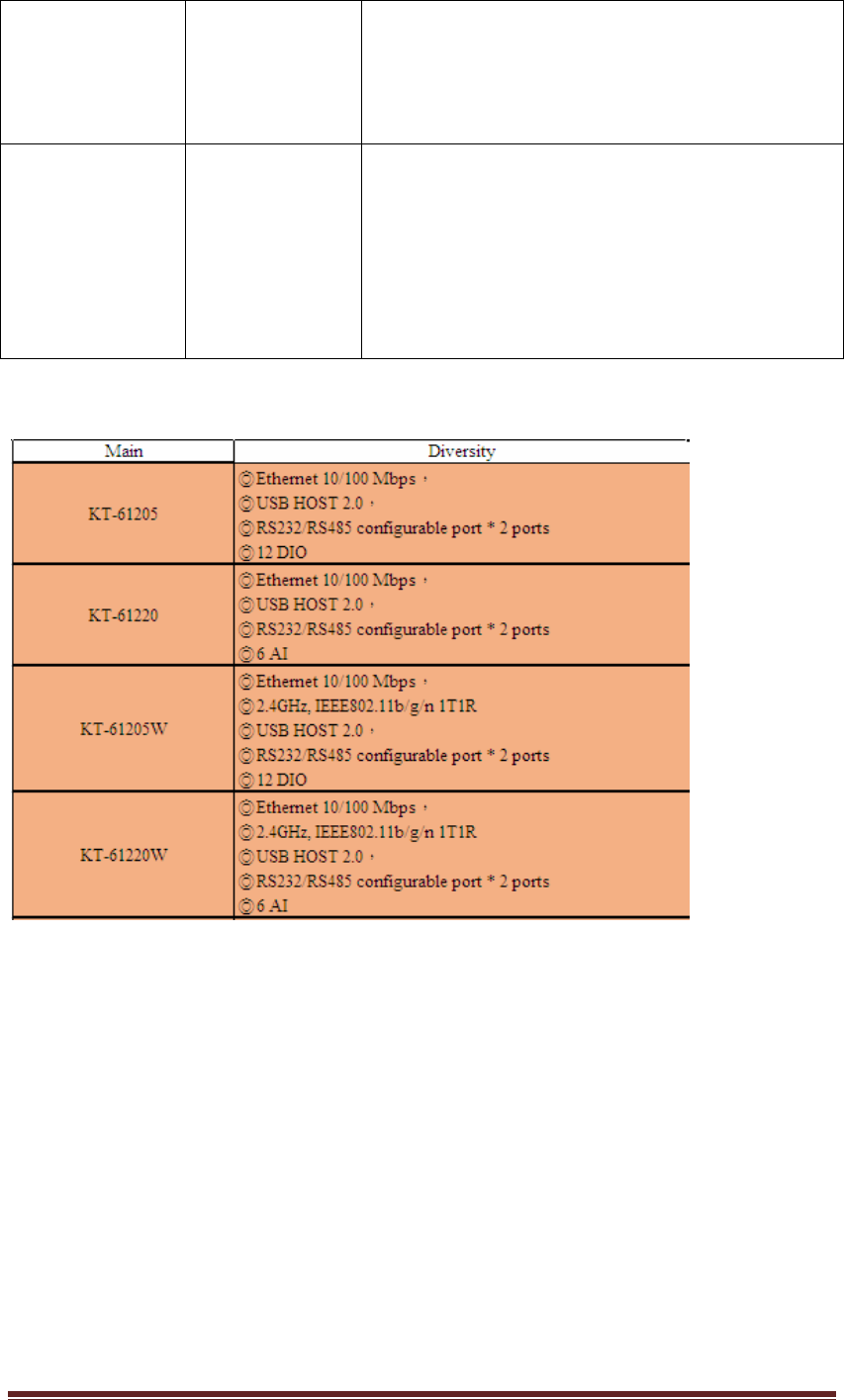
I/OTerminal Block2:(KT‐61220/KT‐61220W)
Signal PinDescription Specification
Ain0~Ain5AnalogInput S/WConfigurable
Currentmode:
0~20mA;4~20mA
Voltagemode:
0~5V;‐5V~+5V;0~10V;
‐10V~+10V

KT‐612XXSIOPlusSeriesControllerUM10
Resolution:16‐bits
LEDIndicators:
LED LEDStatus Description
SystemON
OFF
Blinking
SystemisinNormalOperation
SystemPowerOff
SystemisinSettingMode
AlarmON
OFF
Blinking
Failedtoupgradefirmware
Noalarm
Equipment abnormally warning
LocalON
Blinking
(100ms)
Blinking
(250ms)
LocalMode
Moduleisinbooting
ModuleisingettingIPstate
CloudON
Blinking
(100ms)
Blinking
(250ms)
Blinking(1s)
CloudMode
Moduleisinbooting
ModuleisingettingIPstate
ModuleisfailedtoconnectwithCloudServer
LANOFF
ON
Blink
Ethernetislink‐OFF
Ethernetislink‐ON
Ethernetgotreceivedpacket
COM0OFF
Nodatatransmit
KT‐612XXSIOPlusSeriesControllerUM11
Blinking(Green)
Blinking(Amber)
COM0RS‐485Modetransmit
COM0RS‐232Modetransmit
COM1OFF
Blinking(Green)
Blinking(Amber)
Nodatatransmit
COM1RS‐485Modetransmit
COM1RS‐232Modetransmit
SmartI/O+ControllerSeries(KT‐61205/KT‐61205W/KT‐61220/KT‐61220W)Diversity
2. Installthehardware
(2.1) Connectingthepower:Connectingthe12to24VDCpowerlineinto
KT‐61025/LT‐61205W/KT‐61220/KT‐61220WSIOPlusSeriesterminal
block(TB)。
(2.2) ConnectingtoNetwork:ConnecttheSIOPlusSeriestotheRouterwithan
Ethernetcable。
(2.3) ConnectingtoI/Odevice:ConnecttheSIOPlusSeriesRS232/RS485serial
porttoanotherRS232/RS485I/Odevice.
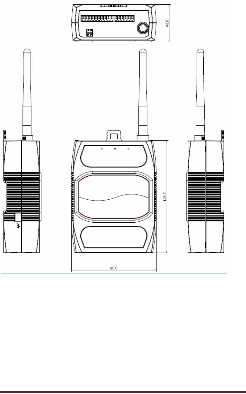
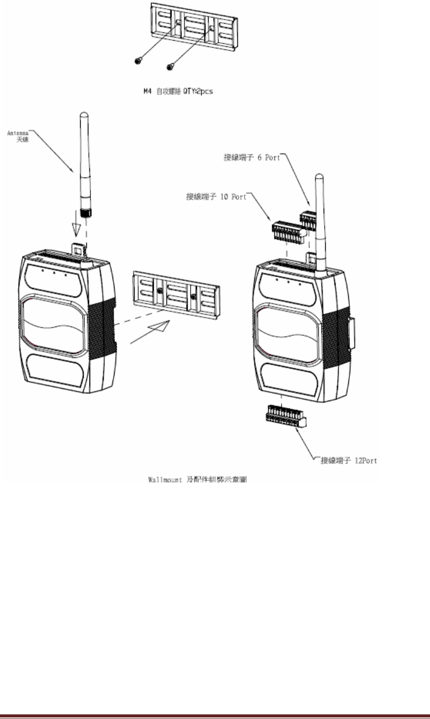
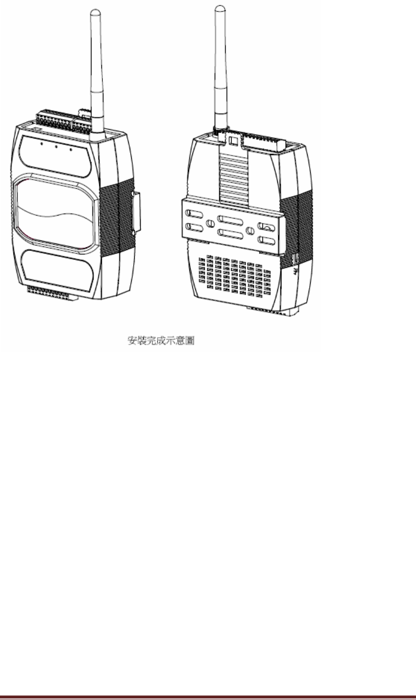
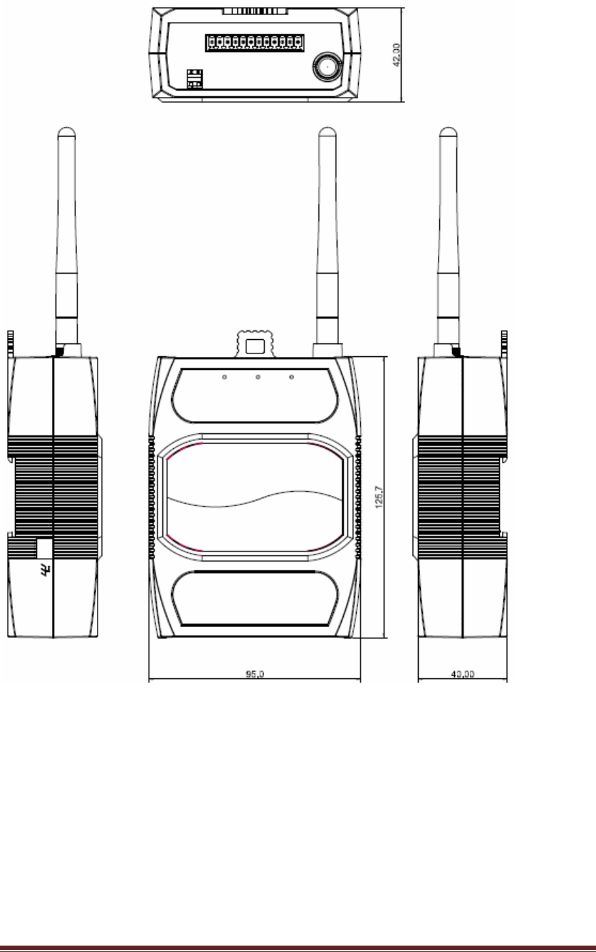
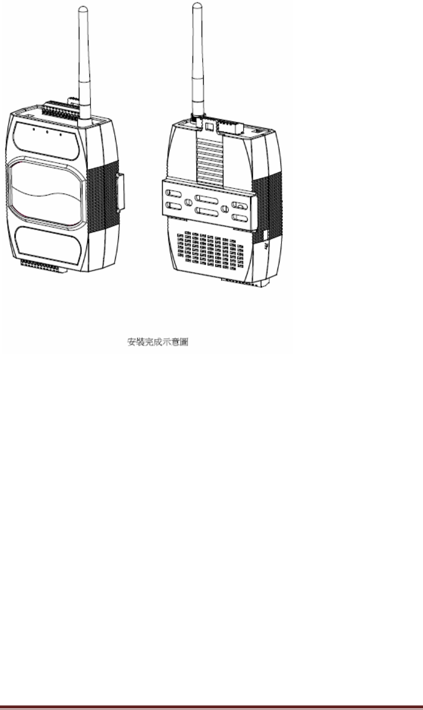
(2.4) Mechanicaldrawingandassemblyasfollowing.
KT‐612XXSIOPlusSeriesControllerUM12
(a).KT‐61205/KT‐61205W
KT‐612XXSIOPlusSeriesControllerUM13
KT‐612XXSIOPlusSeriesControllerUM14
KT‐612XXSIOPlusSeriesControllerUM15
(b)KT‐61220/KT‐61220W

KT‐612XXSIOPlusSeriesControllerUM16
KT‐612XXSIOPlusSeriesControllerUM17
3. DownloadandinstallthePCSoftware
“SmartIXOStudio”isaPCWindowsprogramto
z ConfiguretheSIOPluscontrollers
z EditanddownloadprogramstotheSIOPluscontrollers
z Managecloudaccounts
z DesignandmanageIXO‐View(anuserinterfaceforAPP)projects.
PleasedownloadthezippedPCprogramfromourweb‐siteandunzipittoa
directory.ThesupportWindowsplatformsare:
z WindowsVistaandabove(Windows7,Windows8)
z .NetFramework4.0andabove.
4. ConfigureandmonitortheSIOpluscontrollerviathePCprogram
BeforeyouusethePCprogramtoconfiguretheSIOpluscontroller,pleasemakesure
yourPCisconnectedwiththecontrollerinthesameEthernetswitchintheintranet.
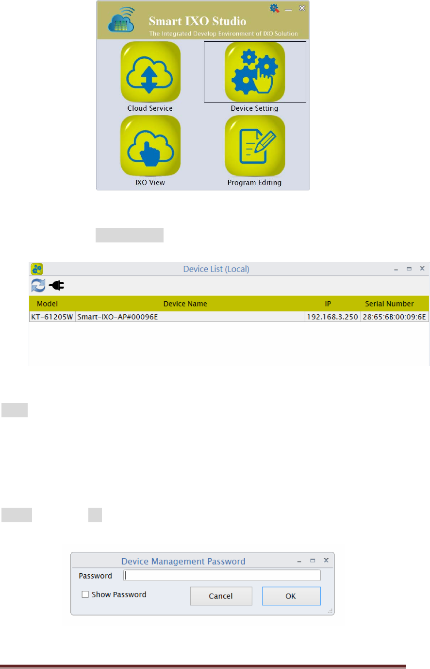
Openthe“SmartIXOStudio”PCsoftwarebyclickingthe“SmartIXOStudio.exe”file
andyouwillseethemainscreenasshowninFigure1.
KT‐612XXSIOPlusSeriesControllerUM18
Figure1:MainscreenofthePCprogram
Pleaseclickonthe“DeviceSetting”iconandyouwillseetheSIOpluscontrolleron
thelistasshowninFigure2
Figure2:Devicelistsearchedintheintranet
Note:Thedefaultdevicenameisoftheformatlike:Smart‐IXO‐AP#0000XXwith
differentserialnumberafterthe#signfordifferentSIOpluscontrollers.Here,we
selecttheSmart‐IXO‐AP#00096E.
Double‐clickthedeviceandadialogwillpopuptoaskyouforthemanagement
passwordofthedeviceasshowninFigure3.Pleaseenterthedefaultpassword:
admin,andselectOK.
Figure3:Enterthedevicemanagementpassword
KT‐612XXSIOPlusSeriesControllerUM19
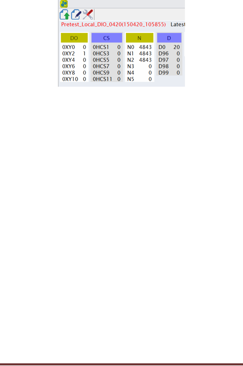
Then,areal‐timedisplayfortheSIOpluscontrollerisshownasFigure4.Thedisplay
willshowthereal‐timevalueorstatusoftheprogrammingcomponentsusedinthe
advancedcontrolblock(logicprogrammingforSIOpluscontrollers).
Figure4:Real‐timedisplayofthelocaldevice
5. Writeandupdateanadvancedcontrolblock(ACB)programtotheSIOplus
controller
Onthissection,wewillwriteasimplecontrolprogram(calledasan“advancedcontrol
block(ACB)”program)tousethefollowingresources:
z 2digitalinputs:DIO0andDIO1(representdas0XY0and0XY1attheprogram).
z 2digitaloutputs:DIO2andDIO3(representedas0XY2and0XY3atthe
program).
z 1counter:CS0(CSrepresentsforCounter‐SetandCCforCounter‐Clear).
ConnectDIO0toapushbutton(calledSet‐BTN)andDIO1toasecondpush
button(Reset‐BTN).
And,connectDIO2toone24VDCLED(calledLED1)andDIO3totheother24VDCLED
(calledLED2).
TheI/OwirinngdiagramisshownasFigure5below.
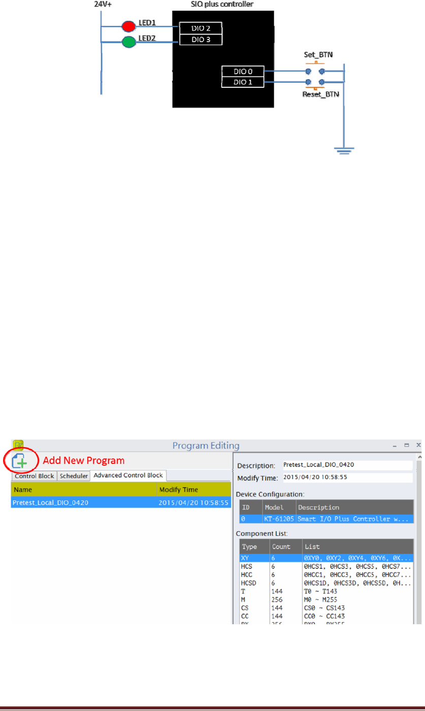
KT‐612XXSIOPlusSeriesControllerUM20
Figure5:IOCircuitforthedemo
Everytimeyoupush‐down/uptheSet_BTN,theLED1willbeturnedon/off,andthe
thecounter(CS0)willaddone.
OncetheCS0counteris5(thethreshold)orabove,theLED2willbeturnedon.
However,youcanpush‐down/uptheReset_BTNtoresetthecountertozeroandthe
LED2willbeturnedoffthen.
HerearethestepstoentertheadvancedcontrolblockprogramonthePCprogram:
(5.1)Backtothemainscreen(asFigure1),clickthe“ProgramEditing”icon,you
canopentheeditorprogram.
(5.2)Selectthe“AdvancedControlBlock”pageandclickthe“AddNew
Program”icononthetop‐leftcornerasshowninFigure6.
Figure6:Addanewadvancedcontrolblockprogram
YouwillseetheprojecteditingscreenasFigure7.
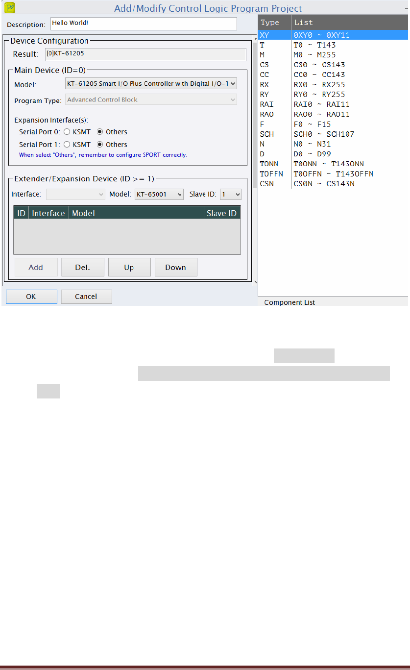
KT‐612XXSIOPlusSeriesControllerUM21
Figure7:ACBProjectWindow
(5.3) Pleaseenterthe“Description”(theprogramname):HelloWorld!andselectthe
MainDeviceModel:KT‐61205SmartI/OPlusControllerwithDigitalI/O–
12chasshowninFigure7.Youwillseeontherightsideforalltheresources
youcanuseinyouradvancecontrolblockprogram,thecomponentlist.
PressOKandgotothenextstep.
(5.4) Youcanstarttoedityourfirstadvancedcontrolblockprogram“HelloWorld!”
(5.4.1)TheAdvancedControlBlockEditorisasfollowing(Figure8).
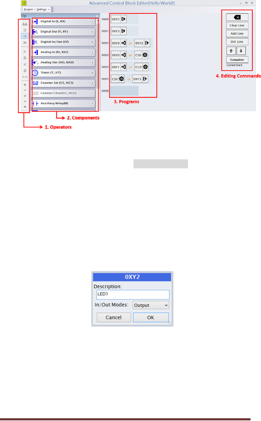
KT‐612XXSIOPlusSeriesControllerUM22
Figure8:ACBEditors
Whereyoucanpressthebuttonsatthe“EditingCommands”paneltoeditthe
controlblockprogram,like“AddLine”toaddanewprogramlineor“DelLine”
todeleteaprogramline.Alineofthecontrolblockprogramiscomposedof
componentsandoperators.Pleaseclickthe“Operators”and“Components”
panelstoselecttherequiredcomponents.
(5.4.2) ConfiguretwoDIOports(DIO2andDIO3)toDigitalOutput:
Clickonthe“DIGITALIN/OUT(XY)”,youcanseealltheDIOsareconfiguredas
Inputsasdefault.Selectthe0XY2andchangetheIn/OutModesasOutput,as
showninFigure9
Figure9:ConfiguringDIO2asOUTPUTmode
Repeatthesamestepstoconfigure0XY3asoutputmode.
Now,boththe0XY2and0XY3arenowconfiguredas“Output”ports.
(5.4.3) Now,youcanenterthefollowingprogram
0XY0 =>0XY2
0XY0 =>CS0
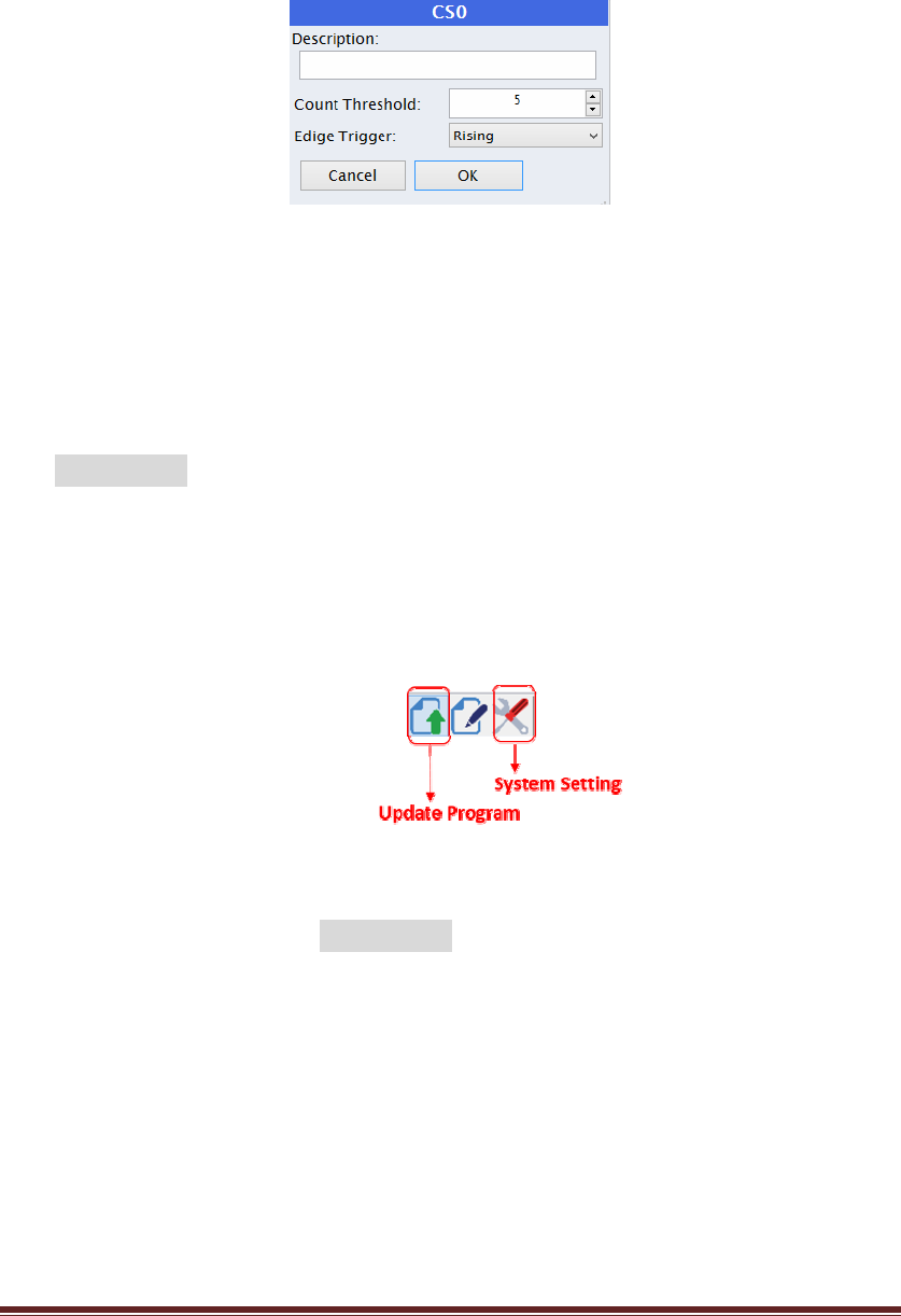
KT‐612XXSIOPlusSeriesControllerUM23
0XY1 => CC0
CS0 =>0XY3
Click the CS0 to set the Count Threshold to 5 as shown inFigure10 .
Figure10:SetCountThresholdto5
After editing the above program and setting the threshold value for CS0, you can
press“Complete”andthesavetheprogrambyreplying“Yes”tothe“SaveCode
Confirm”dialog.Theadvancedcontrolblockprogramwillbesavedasthename
HelloWorld!withitsmodifytimeshownintheACBprojectwindow.
(5.5) UpdatetheprogramtotheSmartIOcontroller:
Backtothemainscreen,pleasefollowtheproceduresonsection4andpressthe
“Updateprogram”icon(asFigure11)ontheup‐leftcornertochoosetheadvanced
controlblockprogramforupdating.
Figure11:Updateprogramtoalocalcontroller
Selecttheprogram(HelloWorld!)andconfirmtoupdate.Then,youwill
seethefollowingreal‐timedisplayoftheresources
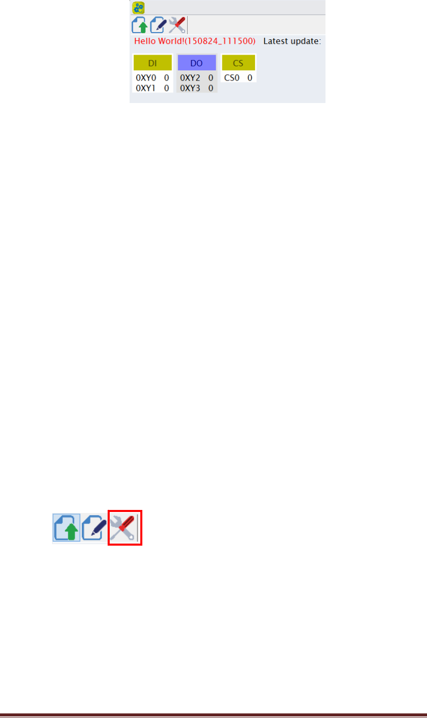
KT‐612XXSIOPlusSeriesControllerUM24
Figure12:Realtimedisplayinlocalmode
Now,youcanstarttopushtheSet_BTNandmonitorthevaluesofDIO0,DIO1,
DIO2,DIO3andCS0(counter)ontheabovescreen.
6. UsetheK‐Cloudservice:
ToenabletheK‐Cloudservice,youmustprepareaSIOpluscontrollerwhichhasnot
beenregisteredtotheK‐Cloudserviceyet.And,youmustconnecttheSmartIO
controllertoanEthernetportwhichisabletoconnecttotheInternet.(Say,an
internetgatewayorSOHOrouterwithseveralEthernetswichports.)
PleasefollowtheprocedureslistedbelowtousetheK‐Cloudservice:
z Createacompanycloudspaceandthecompanyadministratoraccount
z RegistertheSIOpluscontrollertothecompanyspace
z Addauseraccount
z Assignthepermissionrightstotheuseraccount
z Addacloudremoteinput(RX)tothesimple“Helloworld”program
z Usecloudremotecontrol
(6.1) Createacompanycloudspaceandthecompanyadministratoraccount
Backtothemainscreen,pleasefollowtheproceduresonsection4andpressthe
“SystemSetting”icon(asbelow)toconfiguretheSIOpluscontroller.
Youwillseethefollowing“DeviceSetting”pageasshownonFigure13.Pleaseclick
the“NewCompany”iconattheCLOUDSERVICEtoaddanewcompanyaccount.
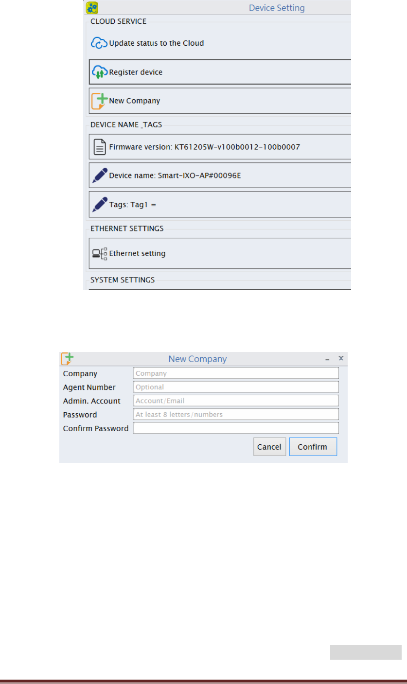
KT‐612XXSIOPlusSeriesControllerUM25
Figure13:DeviceSettingpage
YouwillbeaskedtoentermoreinformationforthenewcomapanyasFigure14
Figure14:Createthecompanyaccount
Pleasetypeinyourowncompanynameandyouremailaddressastheadministrator
account.Itissuggestedtouseavalidemailaccount.AgentNumberisoptional.Your
distributororagentfortheSIOpluscontrollerwillprovidetheAgentNumbertoyou.
Press“Confirm”andwaitforafewsecondsandyouwillgeta“OperationSuccess”
confirmation.Now,youhavesuccessfullycreatedacompanyspaceandan
administratoraccountattheK‐Cloudservice.
(6.2) RegistertheSIOpluscontrollertothecompanyspace
Backtothe“DeviceSetting”page(Figure13),youcannowclickthe“Registerdevice”.
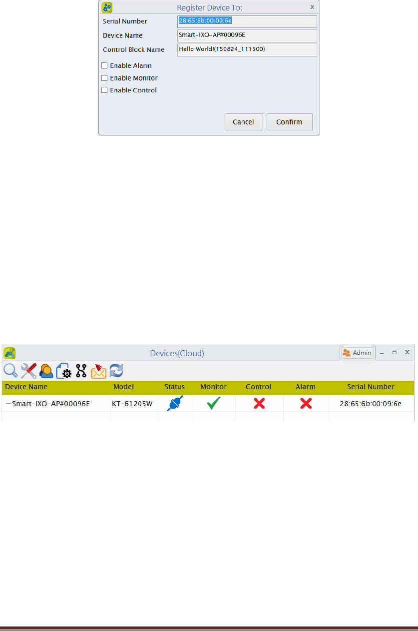
KT‐612XXSIOPlusSeriesControllerUM26
Youwillbeaskedtoenterthecompany,AdminaccountandAdminpassword.Please
entertheinformationyoujusttypeintheprevioussection(Figure14).Thefollowing
information,asshowninFigure15,willbepoppedupforconfirmation.
Figure15:Registerdevicetothecloud
AftersuccessfullyregisterthecontrollertotheK‐Cloudservice,youcanlogintothe
companyspaceandcheckthestatusforthedevice.Gobacktothemainscreen
(Figure1)andclickthe“CloudService”.YouwillseethetheDevices(Cloud)page,as
showninFigure16,whichdisplaysallthedevicesthatbelongtothecompanycloud
space.Atthismoment,thereisonlyoneSIOpluscontrollerregistertothecompany
cloudspace.However,youcanregistermorecontrollerstothecloudspacefollowing
thesamestepspreviously.
Figure16:On‐Linedevicesinthecloud
Clickonthe“‐‐Smart‐IXO‐AP#00096E”line,youwillseeareal‐timedisplayofthe
statusupdateofSIOpluscontrollerasFigure17.
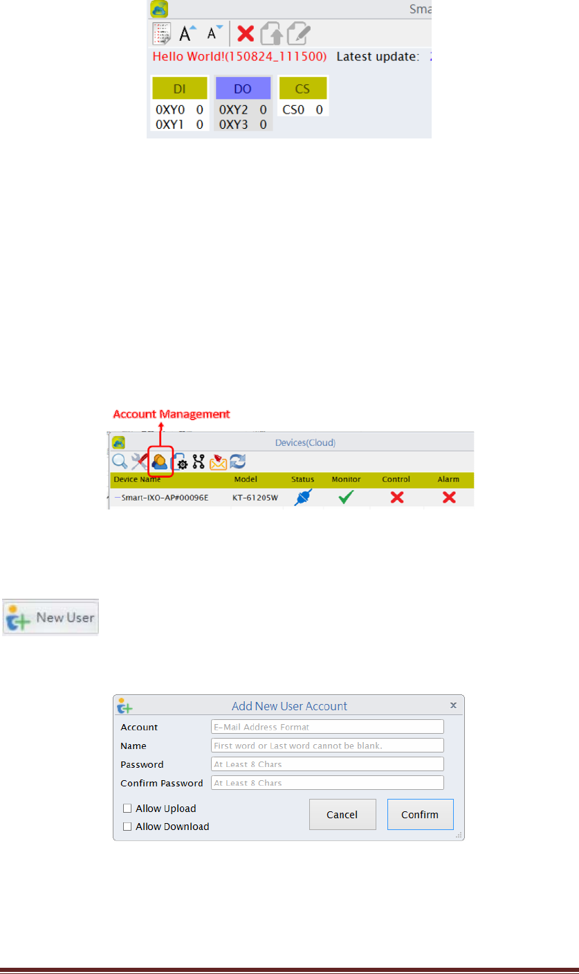
KT‐612XXSIOPlusSeriesControllerUM27
Figure17:RealtimedisplayinCloudmode
(6.3) Addauseraccount.
Inadditiontothepreviliegedadministratoraccount,youmaywanttocreate
someuseraccountsfortheothermembersinthecompany.Theoperationpermission
oftheuseraccountcanbeassignedbytheadministrator.
Herearethesteps:
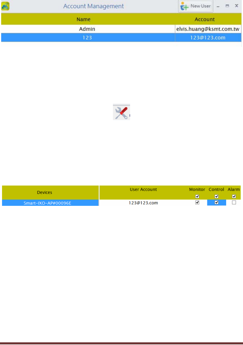
(6.3.1)Inthe“CloudService”,gotothecloudmainpage(Devices(Cloud)),clickonthe
“AccountManagement”iconasFigure18.
Figure18:Clicktheaccountmanagmenticon
PleaseclicktheNewusericonontheupperrightcornerasbelow:
YouwillbeaskedtoprovidetheinformationforthenewuseraccountasFigure19.
Figure19:AddNewUserAccount
Pleaseaddauseraccountforyourcompany.Notethat,asanadministrator,youmust
assignapasswordforthethememberaccount.However,asthememberlogintothe
KT‐612XXSIOPlusSeriesControllerUM28
systemforthefirsttime,he/shewillbeaskedtochangethepasswordthen.
Theaccountmanagementscreenwillshowthe2accounts,Adminandthenew
createduseraccount123,asbelow:
Figure20:Alltheaccountsinthecompany
(6.4) Configurethepermissionrightstothememberaccount.
BacktotheDevices(Cloud)page(Figure16),pleaseclickonthe“Setting”icon(Figure
21)toconfigurethepermissionrightsfortheuseraccount.
Figure21:CloudDeviceSetting
AsshowninFigure22,weassignthe“Monitor”and“Control”permissionrightstothe
memberaccount“123”forthiscontroller.
Figure22:Changethepermissionforauseraccount
The“Monitor”permissionprovidesuser“123”therightstomonitorthestatusofthe
SIOpluscontroller.And,the“Control”permissionallowsuser“123”tosendthe
remoteon/offcommandtotheSIOpluscontroller.Wewilluseacloudremoteinput
(RX)toshowthe“Control”functiononthenextsection.
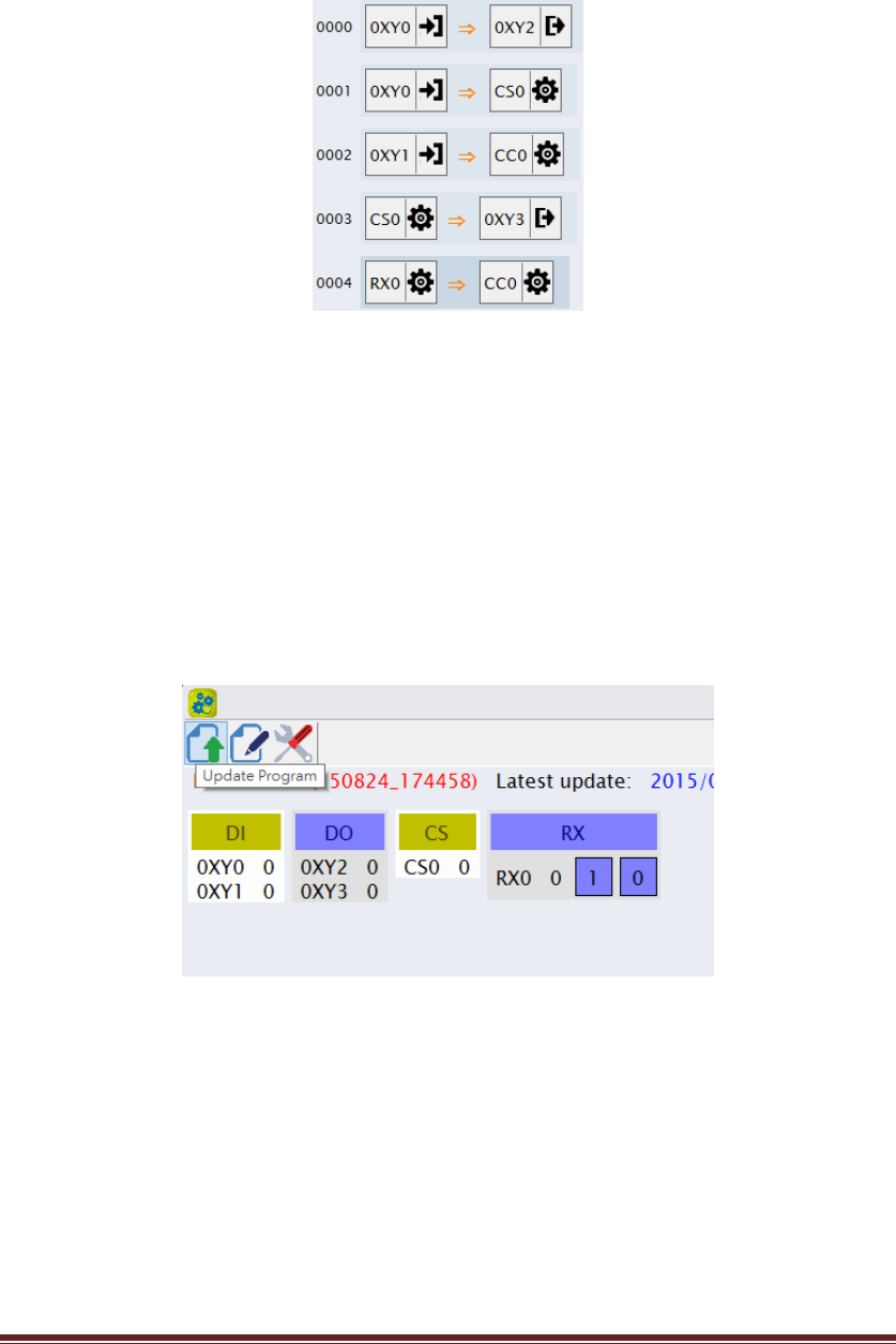
(6.5) Addacloudremoteinput(RX)tothe“Helloworld”program
Backtothemainscreenandclickthe“ProgramEditing”.Pressthe“Helloworld”
programfileandchooseto“Edit”theprogram.Thenaddthefollowinglinetothe
orginalprogram(5.3.3):
KT‐612XXSIOPlusSeriesControllerUM29
RX0 => CC0
ThenthenewprogramisshownasbelowinFigure23.
Figure23:AddanewlinetotheACBprogram
RX0isacloudremoteinputfortheSIOpluscontroller.Itallowstheend‐usertosend
theon/offcommandtochangethestatusofavirtualinputofthecontroller.The
commandisissuedfromthePCprogramandforwardedbytheK‐Cloudserviceto
reachtheSmartIOcontroller.
Pleasefollowtheprocedureson(5.5)toupdatethenewcodethetheSmartIO
controllerandyoucanseethereal‐timedisplayasFigure24.
Figure24:AnewRX0componentisshowninrealtime
Anewcomponent,RX0,isshownonthescreen.Youcanchangethestatusof
RX0bypushingthe1or0buttonofRX0.Thisis,however,justashort‐distance
localWi‐Firemotecontrol.Onthenextsection,wewillperforma
long‐distancecloudremotecontrolovertheInternet.
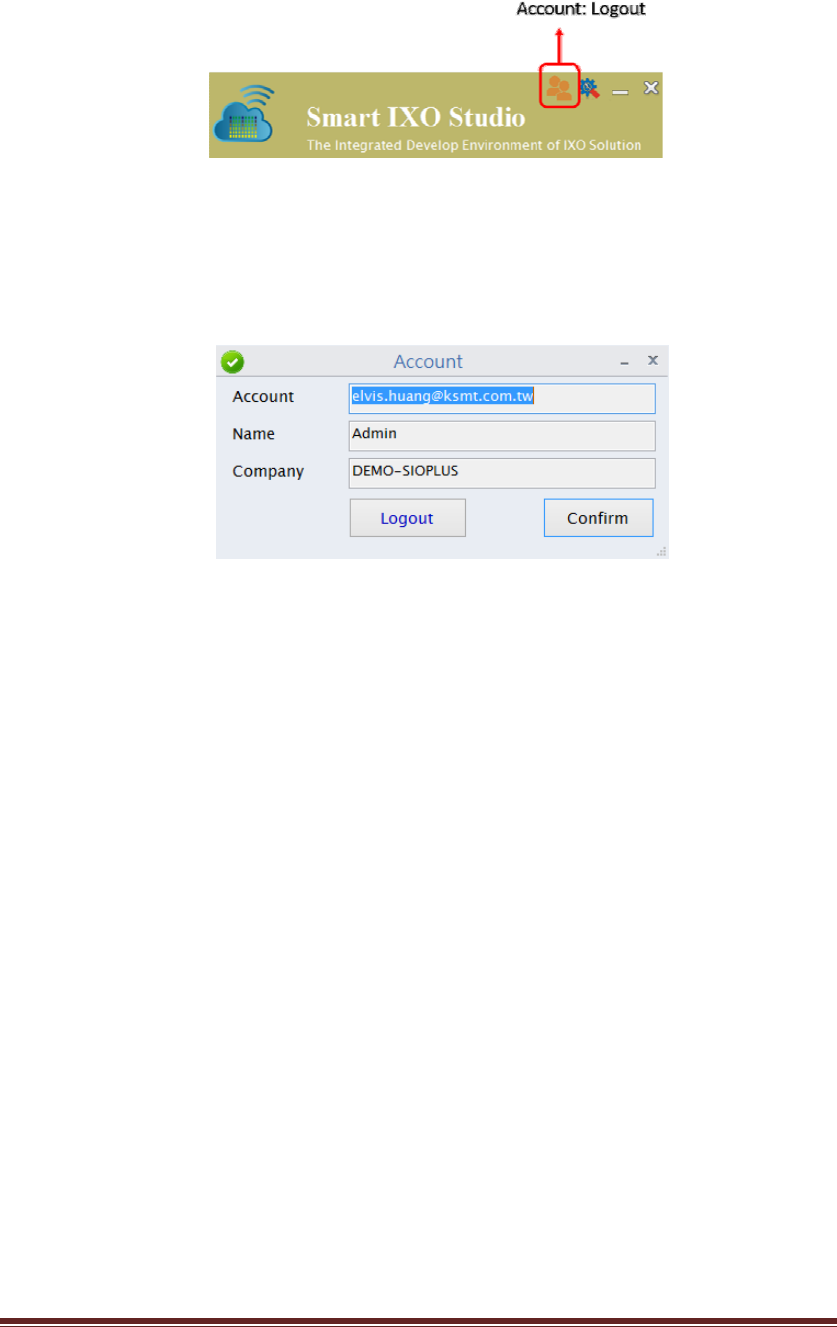
(6.6) Usecloudremotecontrol
KT‐612XXSIOPlusSeriesControllerUM30
Backtothemainscreen,clickontheAccounttologoutasshowninFigure25.
Figure25:AccountLogout
PleaselogoutfromtheadministratoraccountbyclickingLogoutbuttonas
Figure26.
Figure26:Logloutconfirm
PleaseloginagainwiththenewuseraccountyoujustcreatedonSec.(6.3).
Youwillbeaskedtoactivateanewpassword.Pleasetype‐inanewpassword
andconfirmagain.Youarenowloggingasthenewuser.Youcanclickthe
‐‐Smart‐IXO‐AP#000XXXtogettheCloudstatusupdateanddoremotecontrol
bypressingthe1or0buttonofRX0
ItisaremotecontrolfromtheInternet,soyoucangototheplacefarfromthe
Wi‐FicoverageoftheSmartIOcontrollerandresetthecounterCS0andturnoff
theLED2fortheexampleonsection5.

KT‐612XXSIOPlusSeriesControllerUM31
KT-635XXCloud Enabler Series
User Manuals
Version 1.0, Aug. 2015
KT‐612XXSIOPlusSeriesControllerUM32
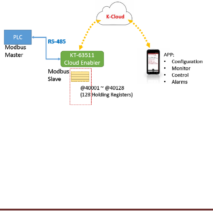
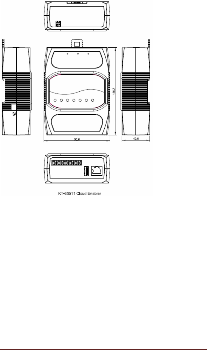
KT‐63511CloudEnabler
PLC(ProgrammableLogicController)andHMI(Human‐MachineInterface)devices
canusetheKT‐635xxcloudenablertoconnecttoacloudservice,sothattheuserscan
controlandmonitorthesedevicesremotelyviatheAPPoftheirownsmartphonesor
tabletPCs.Withtheassistanceofthepush‐basednotificationservice,PLCandHMI
candeliveralarmnotificationsoremailstotheusersinrealtime.Inaddition,the
cloudenableralsoprovidesadata‐loggingfunction,withaUSBpen‐drivepluggedto
thedevice,themonitoringandcontrollingregisterdatawillbeloggedandsavedas
CSVfilesintothepen‐drive.
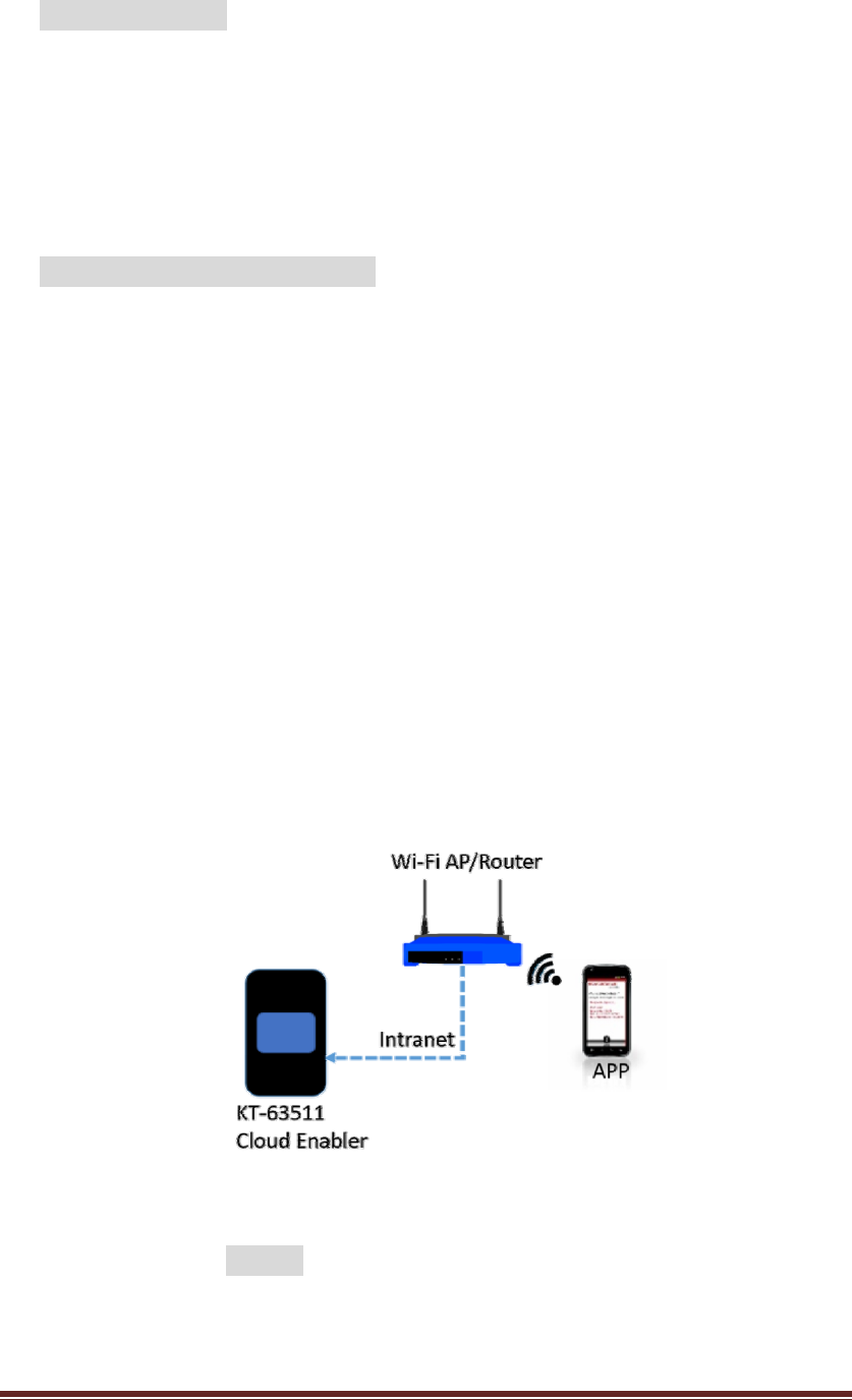
Thecloudenablerprovidesa10/100Ethernettoconnecttothepubliccloudservice
intheinternet.AsaModbusslavedevice,thecloudenableralsoprovidesaRS‐485
porttoconnecttotheModbusmasterdevices,likePLCorHMI.Asillustratedin
Figure27,youtheseetheapplicationarchitectureofthecloudenablers.
Figure27:SystemArchitectureoftheKT‐63511cloudenablers
Thisusermanualwillguideyouthroughthefollowingchapterstounderstandthe
operationsoftheKT‐635xxCloudEnabler:
z Understandingthehardware
z Installingthehardware
z DownloadingandinstallingtheAndroidAPP
z Creatingthecompany,systemadministratoranduseraccounts
KT‐612XXSIOPlusSeriesControllerUM33
z Configuringthecloudenabler
z Configuringthemobusregisters
z Datalogging
1. Understandingthehardware
Hardwaredescription:
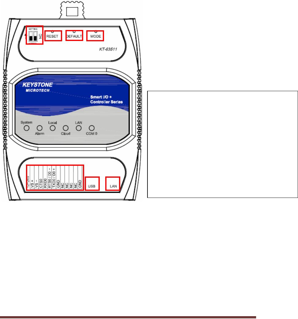
KT‐635xxCloudEnableproductoverview:
1.Normal/Setting:NormalModeorSettingMode
2.Reset:SystemResetPushButton.
3.Default:ResettoFactorydefaultsetting,notinclude
Modbussetting.
4.Mode:SwitchtoLocalModeorCloudMode.
5.TerminalBlock:ForDC12~24Vpowerinputand
RS232/RS485signalconnection.
6.USB:USB2.0Pen‐drivepluginut.
7:LAN:EthernetRJ45cablepluginput.
1
2
3
4
5
6
7
KT‐612XXSIOPlusSeriesControllerUM34
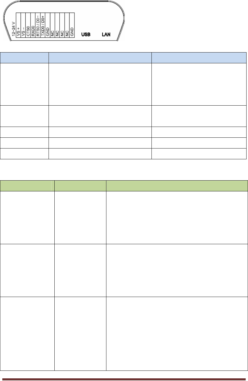
PanelGuide
I/OTerminal Block:
PinAssignDescription:
Signal PinDescription Specification
TXD0
RTS0
RXD0
CTS0
RS232UARTserialPort Maximumbaudrate:
115200bps
TXD0/D0+
RXD0/D0‐
2‐wireRS48UARTserialPort Maximumbaudrate:
921600bps
VS‐/VS+DCPowerInput +12V~+24V
USBUSB2.0Pen‐drivePlug SavedataintoUSBPen‐drive
GNDSignalGND
LEDIndicators:
LED LEDStatus Description
SystemON
OFF
Blinking
SystemisinNormalOperation
SystemPowerOff
SystemisinSettingMode
AlarmON
OFF
Blinking
Failedtoupgradefirmware
Noalarm
Equipment abnormally warning
LocalON
Blinking
(100ms)
Blinking
(250ms)
LocalMode
Moduleisinbooting
ModuleisingettingIPstate

KT‐612XXSIOPlusSeriesControllerUM35
CloudON
Blinking
(100ms)
Blinking
(250ms)
Blinking(1s)
CloudMode
Moduleisinbooting
ModuleisingettingIPstate
ModuleisfailedtoconnectwithCloudServer
LANOFF
ON
Blink
Ethernetislink‐OFF
Ethernetislink‐ON
Ethernetgotreceivedpacket
COM0OFF
Blinking(Green)
Blinking(Amber)
Nodatatransmit
COM0RS‐485Modetransmit
COM0RS‐232Modetransmit
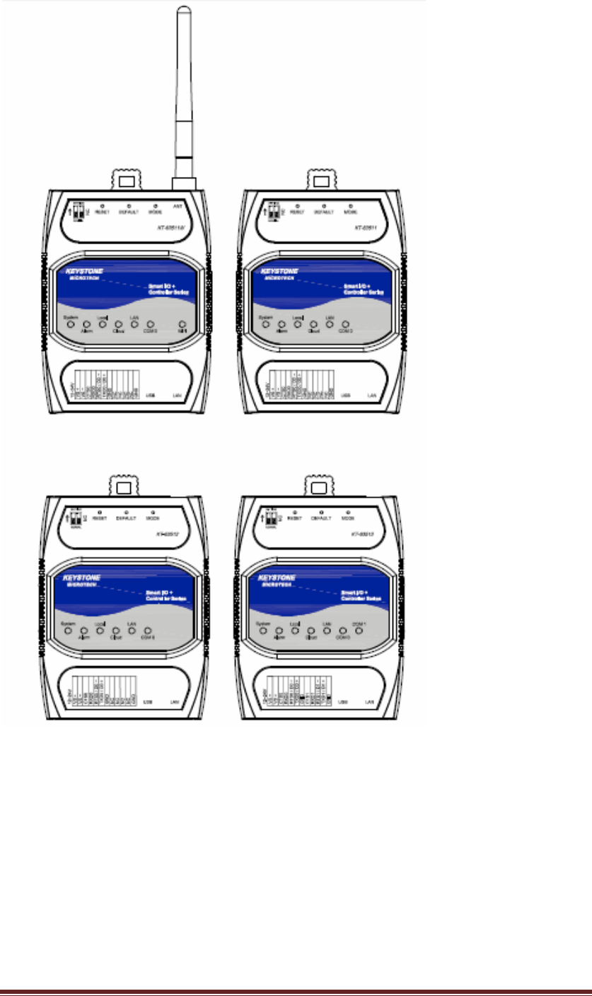
KT‐635XXCloudEnableSeriesProductDifferentiation:
MainModelFeatureList
KT‐63511◎CloudEnabler
◎Ethernet10/100Mbps,
◎USBHOST2.0,
◎RS232/RS485configurableport*1ports
◎128Registers(SW)
KT‐63511W◎CloudEnabler
◎Ethernet10/100Mbps,
◎2.4GHz,IEEE802.11b/g/n1T1R
◎USBHOST2.0,
◎RS232/RS485configurableport*1ports
◎128Registers(SW)
KT‐63512◎CloudEnabler
◎Ethernet10/100Mbps,
◎USBHOST2.0,

KT‐612XXSIOPlusSeriesControllerUM36
◎RS232/RS485configurableport*1ports
◎256Registers(SW)
KT‐63513◎CloudEnabler
◎Ethernet10/100Mbps,
◎USBHOST2.0,
◎RS232/RS485configurableport*2ports
◎128Registers(SW)
KT‐63514◎CloudEnabler
◎Ethernet10/100Mbps,
◎USBHOST2.0,
◎RS232/RS485configurableport*2ports
◎256Registers(SW)
KT‐63514W◎CloudEnabler
◎Ethernet10/100Mbps,
◎2.4GHz,IEEE802.11b/g/n1T1R
◎USBHOST2.0,
◎RS232/RS485configurableport*2ports
◎256Registers(SW)
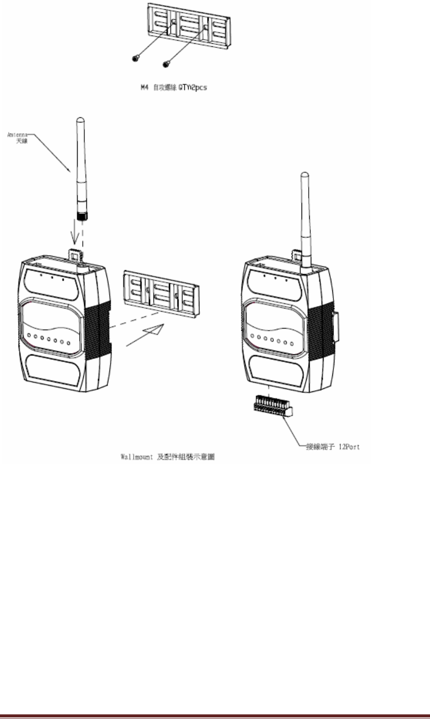
2. HardwareInstalling
(2.5) Connectingthepower:Connectingthe12to24VDCpowerlineinto
KT‐635xxterminalblock(TB)。
(2.6) ConnectingtoNetwork:ConnecttheKT‐635xxtotheRouterwithan
Ethernetcable。
(2.7) ConnectingtoI/Odevice:ConnecttheKT‐635xxRS232/RS485serialportto
anotherRS232/RS485I/Odevice.
(2.8) Mechanicaldrawingandassemblyasfollowing.
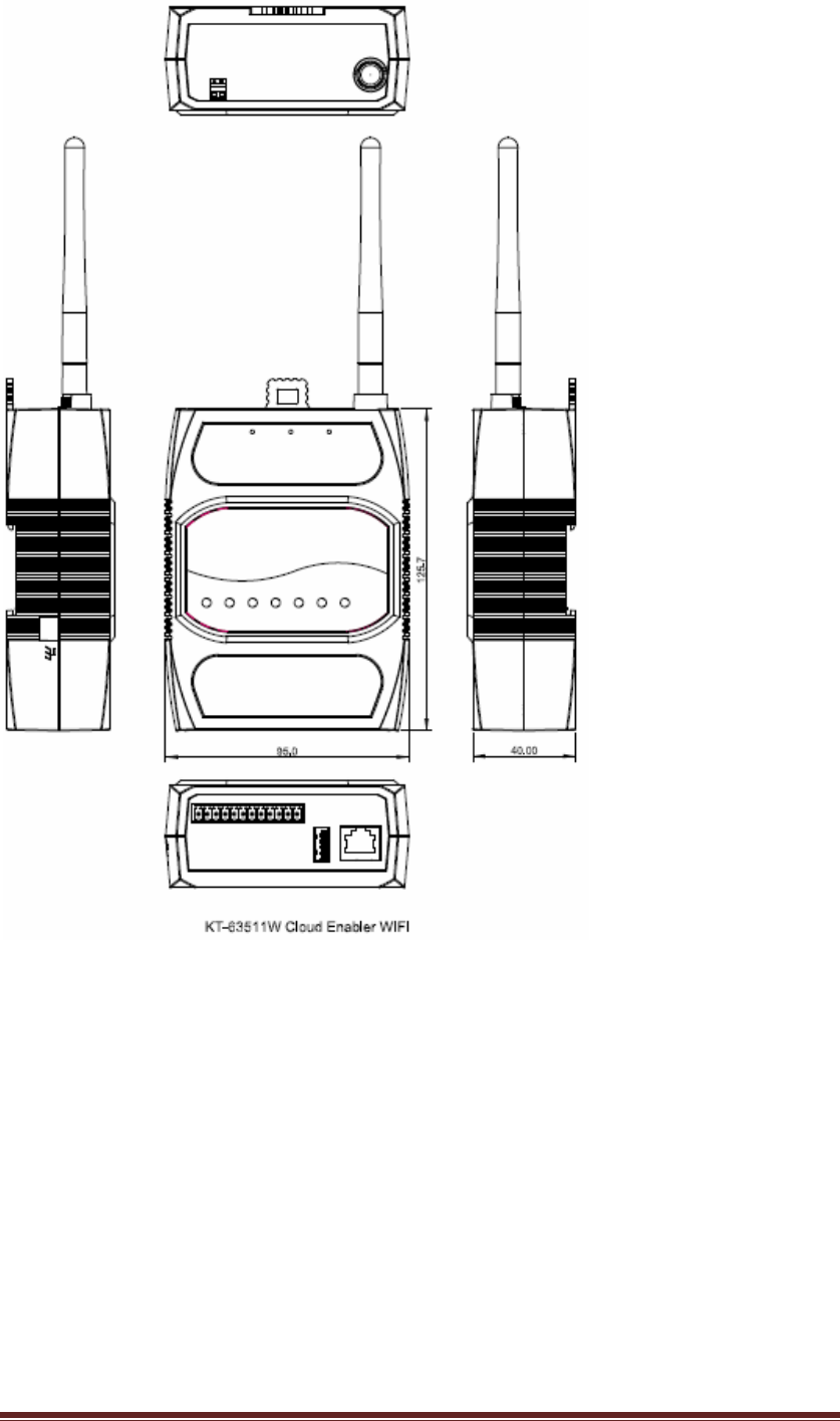
KT‐612XXSIOPlusSeriesControllerUM37
KT‐612XXSIOPlusSeriesControllerUM38
KT‐612XXSIOPlusSeriesControllerUM39
KT‐612XXSIOPlusSeriesControllerUM40
KT‐612XXSIOPlusSeriesControllerUM41
3. DownloadingandinstallingtheAndroidAPP
PleasefollowtheinstrctionsintheURLtodownloadandinstalltheAPP.
https://bitbucket.org/cloudenabler/release/wiki/Home
4. Creatingthecompany,systemadministratoranduseraccounts
Beforeyoustarttousethecloudserviceforthecloudenablers,youshouldopenthe
APPtocreateacompanyaswellasthesystemadministratoraccount.
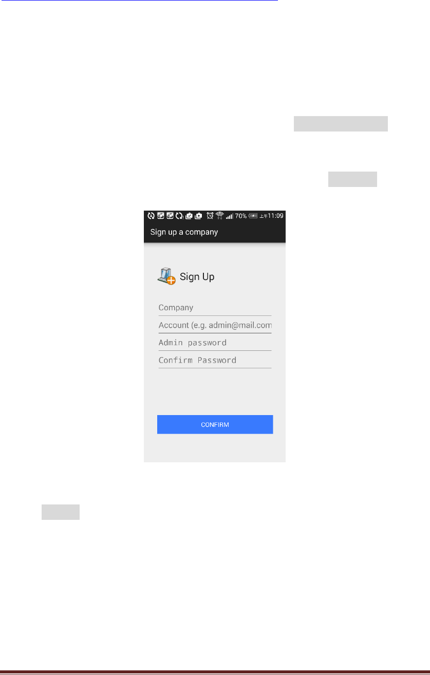
(4.1)Createthecompanyandthesystemadministratoraccount:
Clicktoopenthe“CloudEnabler”APP,youcantouchthe“Signupacompany”,then
youwillseethescreenshowasFigure28.
FollowingthehintsintheAPPtoentertheinformationandtouchCONFIRM,thenyou
willcreatethecompanyandsystemadministratorinthecloud.
Figure28:Signupanewcompany
Please“SIGNIN”thesystemadministratoraccount,thenyouwillthenbedirectlyto
themainscreenasshowninFigure29.
KT‐612XXSIOPlusSeriesControllerUM42
Figure29:MainscreenoftheAPP
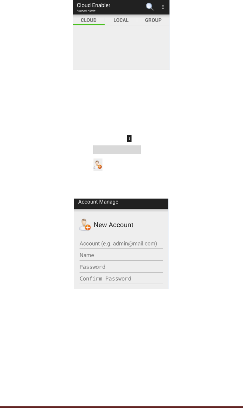
(4.2)Addusersaccounts
Logininbythesystemadministratoraccount,youcanstarttocreatemoreuser
accountsforthecompany.Pleasetocuhthe ontheupleftcornerofthemain
screen(Figure29)andselecttheAccountManagetocreate,editandremovethe
useraccounts.Pleasetouchthe ontheupleftcornerofthe“AccountManage”
page,youcanaddanewuseraccountforthiscompanyasshowninFigure30.
Figure30:Addnewuseraccounts
5. Configuringthecloudenabler
Inthissection,wewillprovidethestepsto:
z Configurethesystemsettingsofthecloudenabler
z Registerthecloudenablerintothecompanyaccount
(5.1)Configurethesystemsettingsofthecloudenabler
Followingarethefactorydefaultsettingsforthecloudenabler:
KT‐612XXSIOPlusSeriesControllerUM43
IPDefaultSettings:
z StaticIP
z IPaddress:192.168.3.250
z NetMask:255.255.255.0
z DafaultGateway:192.168.3.254
z DNSServer:168.95.1.1
COM‐0SerialPortDefaultSetting:
z RS‐485mode
z ModbusSlaveID:1
z ModbusOperationMode:RTU/Slave
z Baud‐Rate:19200bps
z Databit:8bits
z ParityCheck:None
z Stopbit:1bit
YoucanusetheAPPtoadjustthesettingsoftheKT‐635xxcloudenabler,say,
ModbusSlaveID,baudrateoftheCOM‐0serialports…,etc).However,you
shouldhaveyourAndroidmobilephoneortabletPCaccesstheintranetviaa
Wi‐FiAP(AccessPoint)orrouter,sothattheAPPcandirectlyconnectwiththe
cloudenablerintheintranet(notthroughtheinternet)asshowninFigure31.
PlugtheRJ‐45cabeltotheLANportofcloudenablerandturnonthepower.
Figure31:APPandCloud‐EnablerintheIntranet
OpentheAPPandSIGN‐INusingthesystemadministratoraccount(Admin),you
willseethemainscreenpage(asFigure29),pleaseslideintothe“Local”page
andyoumayseeanicon(markedasCE)asshowninFigure32.
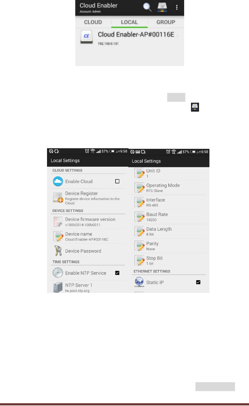
KT‐612XXSIOPlusSeriesControllerUM44
Figure32:Localdevicescreen
Pleasetouchtheiconandyouwillgotothe“LocalSettings”pagesasshown
inFigure33below.(Thedefault“DevicePassword”isadmin.)
IfyoucannotfindtheCEiconinFigure32,youcantouchthe icononthe
left‐uppercornerofthe“Local”pageandtype‐intheIPaddressofthe
cloud‐enabler,thenyouwillseethepageasFigure33.
Figure33:LocalSettingsforthecloudenabler
YoucanchangetheCloud/Time/COM‐0/ETHERNETsettingsofthiscloudenabler.
Somechnagesofthesettingmightcausethere‐startofthecloudenabler.
(5.2)Registerthecloudenablerintothecompanyaccount
Thenextstepistoregisterthecloudenablertothecloudcompanyaccountso
thattheusercanusetheAPPtoremotelymonitorandcontrolthisdevice.
Followingthestepsonprevioussection(5.1),youcangototheLocalSettings
KT‐612XXSIOPlusSeriesControllerUM45
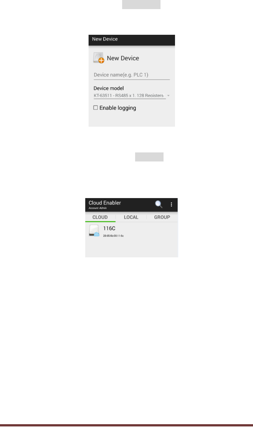
page(Figure33),pleaseturn‐onthe“EnableCloud”onCLOUDSETTINGsand
touchthe“DeviceRegister”,theyouwillseethescreenasshownonFigure34.
Figure34:Registeranewdevicetothecloud
PleasetypeintheDevicenameandpressCONFIRM,thecloudenablerwillbe
registeredtothecompanyaccount.Backtothemainscreen,slidetothe
“CLOUD”page,youwillseeacloudenablershownas.
Figure35:acloudenabler116Cisonline
Inthiscase,thecloudenablernamed“116C”issuccessfullyregisteredand
on‐lineinthecompanyaccount.
6. Configuringthemobusregisters:
ThecloudenablerconnectswiththeModbusmasterdevice(PLCorHMI)viathe
RS‐485serialport(asshowninFigure27).OperatedasaModbusslave,thecloud
enablersupport128holdingregistersthatallowsthePLC/HMItoread/writethrough
theModbus/RTUorModbus/ASCIIprotocol.
IntheAPP,theholdingregistersarerepresentedfromnumber40001to40128.
However,somePLCorHMIusethedataaddress0~127torepresentthese
addresses.
KT‐612XXSIOPlusSeriesControllerUM46
YoucanusetheAPPtoconfiguretheaccessrights(Modbus‐WriteorAPP‐Write)and
thedatatypes.(16‐bitinteger,32‐bitinteger,32‐bitIEEE754floatingpoing…,etc).
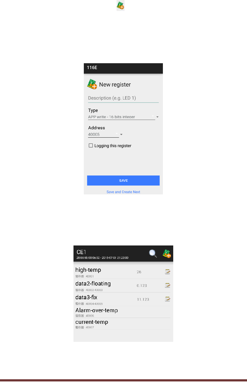
PleaseclickthecloudenablericonasshowninFigure35andyouwillbedirectedto
theclouddevicepage.Pleasepressthe icontoconfigureanewregisteras
showninFigure36.Pleasetypeinthedescriptionfortheregister,selectthedata
types(alsotheaccessrights),assigntheregisteraddressandspecifywhethertolog
thisregisterintoadatalog.
Figure36:Addanewregister
Onceyouconfigureallthenecessaryregisters,youcanseealltheregistersasshown
inFigure37.
Figure37:Alltheconfiguredregistersforacloudenabler
7. DataLogging
KT‐612XXSIOPlusSeriesControllerUM47
KT‐635xxcloudenablersupportsthedataloggingfunctionfortheconfigured
registers.YoushouldplugaUSBpen‐driveintotheUSBportastherecordingstorage
media.OnceyouusetheAPPtostartlogging,alltheconfiguredregistervaluewillbe
loggedasaCSVfileundera/YYYYMM/directoryintheUSBpen‐drive,whereYYYY
representstheyear,say2015,andMMrepresentsthemonth,say08forAug.
Everytimeyouwanttochangetheloggingconfiguration,say,whethertologfor
someregisters,youshouldstoploggingfirst.Oncedataloggingisrestartedagain,
anewCSVfilewillbecreated.Upto100CVSfileswillbecreatedforonedaywith
thetrailingnumberfrom00to99onthefilename.
OnFigure36,youcanseeanoption,Loggingthisregister,forloggingconfiguration.
However,youcanalsolong‐presstheconfiguredregister(asshowninFigure37)until
itpopupascreen,thenyoucouldselect“Edit”toturnon/offthe“Eablelogging”
option.
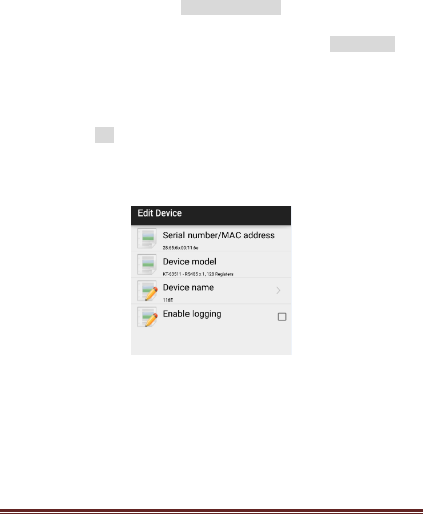
Tostartorstopthedataloggingforacloudenabler,pleaselong‐pressthedevice
nameformorethan1secondonthe“Cloud”pageofthemainscreen(asshownin
Figure35).Select“Edit”onthepop‐upscreenandyouwillbedirectedtothe“Edit
Device”pageasshowninFigure38.Youcanturnon/offthe“Enablelogging”option
tostartorstopdataloggingforthiscloudenabler.
Figure38:Editthecloudenabler
YoucanturnoffdataloggingandremovetheUSBpen‐drivetogettheloggedCSV
files.However,aninternalFTPserverisalsobuiltinthecloudenablersothatyou
candownloadtheloggedfilesviaaFTPclientsoftwareasshowninFigure39.
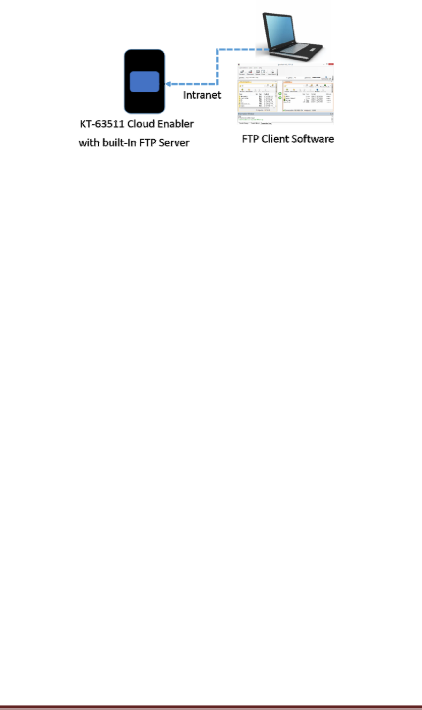
KT‐612XXSIOPlusSeriesControllerUM48
Figure39:FTPtogetlogfiles
DefaultFTPaccountis:ftp
DefaultFTPpasswordis:admin(thesameasthedevicesettingpassword,youcan
changethepasswordintheAPPlater.)
PleasechooseaUSBpen‐drivewhichsupportstheFAT32filesystem.Ingeneral,a
pen‐drivewith2GBto32GBcapacitywillmeettherequirements.
END