King of Fans 52ESWS 52 inch Emswell User Manual HDC 52in Emswell 52 ESW
King of Fans, Inc. 52 inch Emswell HDC 52in Emswell 52 ESW
UserManual.wiki
>
King of Fans
>
52ESWS User Manual
User Manual
Navigation menu
Upload a User Manual
Namespaces
Wiki Guide
HTML
PDF
Info
Views
User Manual
Discussion / Help
Navigation
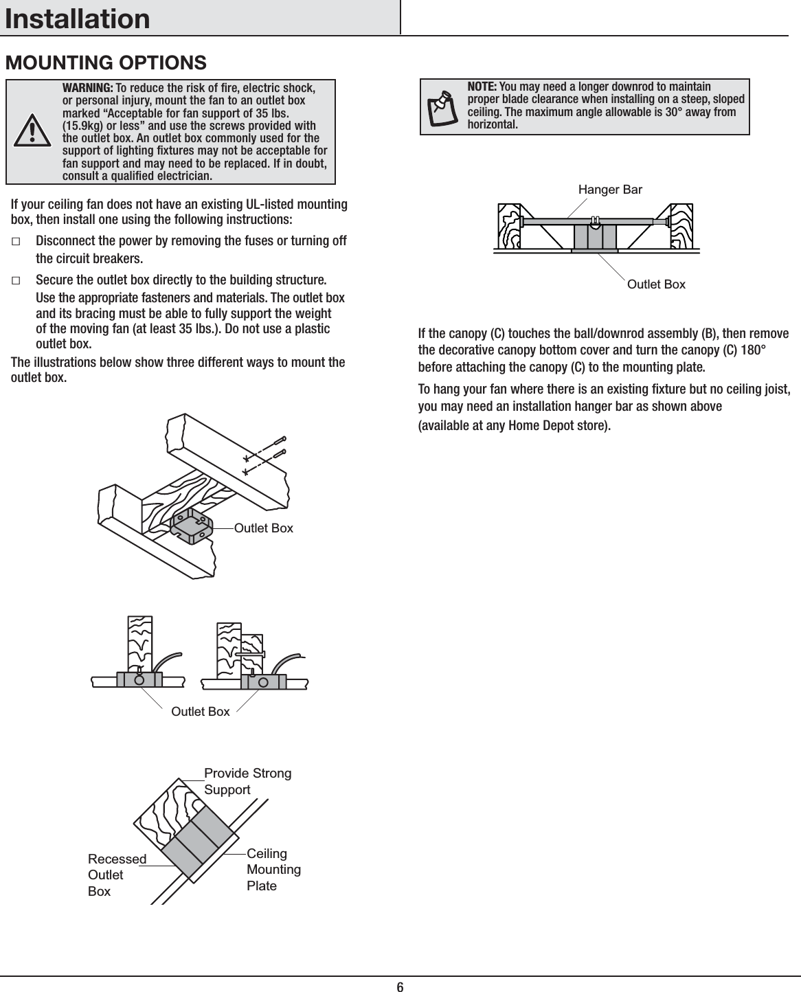

![6InstalaciónOPCIONES DE MONTAJEADVERTENCIA: Para reducir el riesgo de incendio, descarga eléctrica o lesiones personales, instala sólo en una caja eléctrica clasicada como “apropiada para sostener ventiladores de 35 lb (15.9kg) o menos”, y usa sólo los tornillos incluidos con la caja eléctrica. Las cajas eléctricas utilizadas comúnmente para el soporte de lámparas pueden no servir como soporte de ventilador y tal vez deban reemplazarse. En caso de duda, consulta a un electricista calicado.Si tu ventilador de techo no tiene una caja de montaje aprobada por UL, instala una siguiendo las instrucciones a continuación:ƑDesconecta la energía retirando los fusibles o apagando los cortacircuitos.ƑAsegura la caja eléctrica directamente a la estructura de la edicación. Usa los sujetadores y materiales apropiados. La caja eléctrica y su soporte tienen que sostener completamente el peso en movimiento del ventilador [al menos 35 libras (15.9kg)]. No uses una caja eléctrica de plástico.Las ilustraciones más abajo muestran tres formas distintas de montar la caja eléctrica.Si la cubierta (C) toca el conjunto del tubo bajante/bola (B), retira la tapa inferior decorativa de la cubierta y gira 180º esta última (C) antes de jarla a la placa de montaje.Para colgar el ventilador donde ya haya una lámpara pero ninguna viga de techo, tal vez necesites una barra colgante como se muestra más arriba (disponible en cualquier tienda de The Home Depot).NOTA: Tal vez necesites un tubo bajante más largo para mantener la altura mínima adecuada de las aspas, al instalar el ventilador en un techo inclinado. El ángulo máximo permitido es 30º con respecto a la horizontal.CajaeléctricaCaja eléctricaCajaeléctricaempotradaSoporte fuertePlaca de montajeen techoCaja eléctricaBarra para colgar](https://usermanual.wiki/King-of-Fans/52ESWS/User-Guide-2673899-Page-22.png)
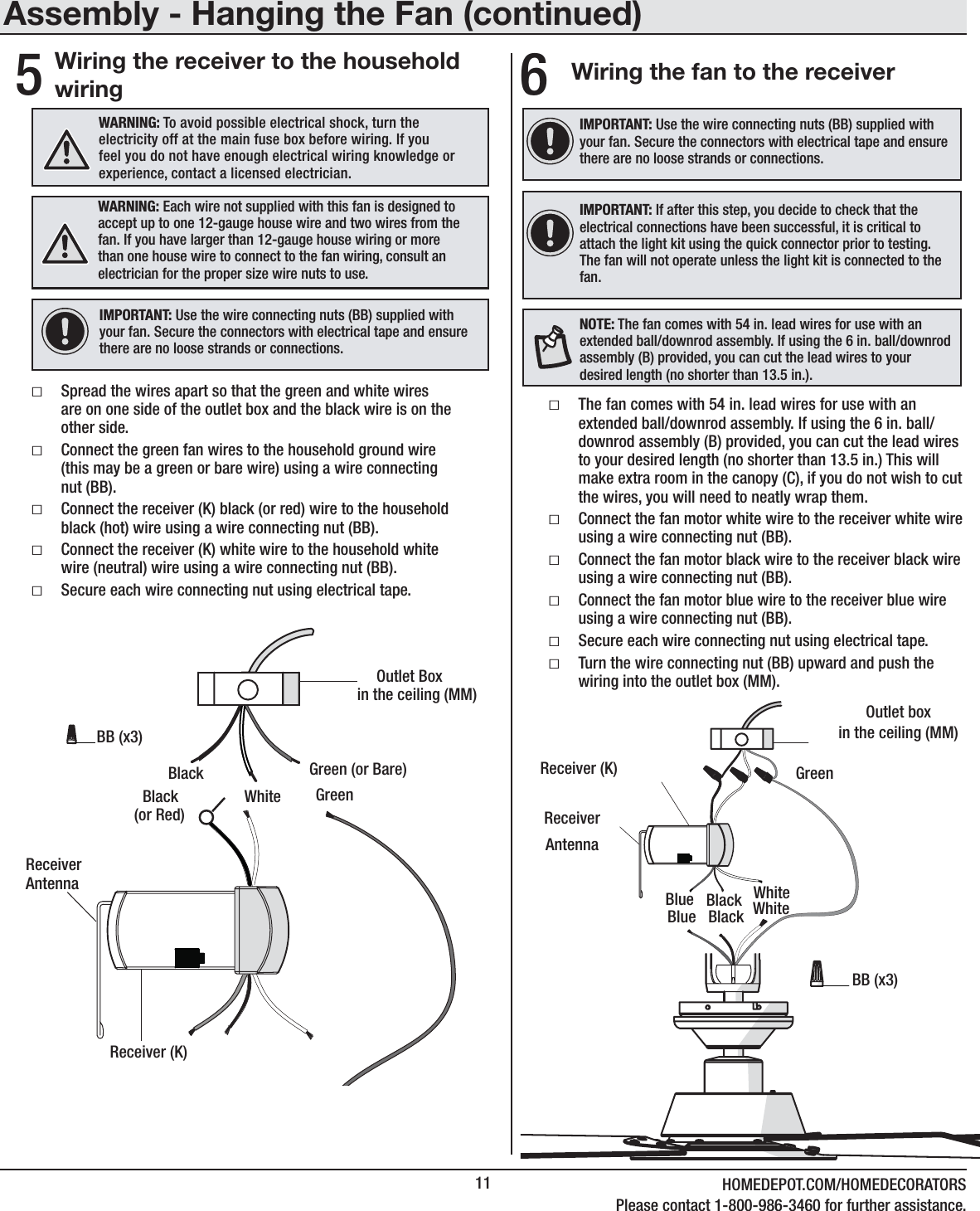
![11 HOMEDEPOT.COM/HOMEDECORATORSPara más asistencia, llama al 1-800-986-3460.Ensamblaje - Cómo colgar el ventilador (continuación)5Cómo conectar los cables del receptor a los cables del hogarIMPORTANTE: Usa las tuercas de conexión de cables (BB) incluidas con tu ventilador. Sujeta los conectores con cinta de electricista y asegura que no haya conexiones ni cables sueltos.ADVERTENCIA: Cada cable no suministrado con este ventilador debe estar diseñado para aceptar hasta un cableado doméstico calibre 12 y dos cables del ventilador. Si tienes un cableado doméstico que exceda del calibre 12 o más de un cable doméstico para conectar al cableado del ventilador, consulta a un electricista para el tamaño adecuado de las tuercas para cables a usar.ƑSepara los cables de manera que aquellos verde y blanco queden de un lado de la caja eléctrica y el negro quede del otro lado. ƑConecta los cables verdes del ventilador al cable con conexión a tierra de la casa (este puede ser verde o pelado) con una tuerca de conexión de cables (BB).ƑConecta el cable negro (o rojo) del receptor (K) al cable negro (positivo) del hogar, usando una tuerca de conexión de cables (BB).ƑConecta el cable blanco del receptor (K) al cable blanco del hogar (neutro), usando una tuerca de conexión de cables (BB).ƑAsegura cada tuerca de conexión de cables con cinta de electricista. Negro(o rojo)BlancoNegroVerdeBlancoReceptor (K)BB (x3)1234ON DIPCaja eléctrica en el techo (MM)Verde (o pelado)Antena del ReceptorADVERTENCIA: Para evitar una posible descarga eléctrica, apaga la electricidad en la caja principal de fusibles antes de instalar el cableado. Si crees que no tienes suciente conocimiento o experiencia sobre cableado eléctrico, contacta a un electricista certicado.Cómo conectar los cables del ventilador al receptorƑEl ventilador viene con cables terminales de 1.37 m para usar con un ensamblaje extendido de tubo bajante/bola. Si usas el ensamblaje de tubo bajante/bola (B) de 15.2 cm (6 plg) incluido, puedes recortar los cables terminales al largo deseado [no menos de 34.3 cm (13.5 plg)]. Esto dejará más espacio en la cubierta (C). Si no quieres cortar los cables, deberás enrollarlos cuidadosamente. ƑConecta el cable blanco del motor del ventilador al cable blanco del receptor usando una tuerca de conexión de cables (BB).ƑConecta el cable negro del motor del ventilador al cable negro del receptor usando una tuerca de conexión de cables (BB).ƑConecta el cable azul del motor del ventilador al cable azul del receptor usando una tuerca de conexión de cables (BB).ƑAsegura cada tuerca de conexión de cables con cinta de electricista. ƑGira la tuerca de conexión de cables (BB) hacia arriba y coloca el cableado dentro de la caja eléctrica (MM).6IMPORTANTE: Usa las tuercas de conexión de cables (BB) incluidas con tu ventilador. Sujeta los conectores con cinta de electricista y asegura que no haya conexiones ni cables sueltos.Caja eléctricaen el techo (MM)Receptor (K)AzulAntenadel receptorNegro BlancoVerdeBB (x3)1234ON DIPAzul Negro BlancoNOTA: El ventilador viene con cables terminales de 1.37 m para usar con un ensamblaje extendido de tubo bajante/bola. Si usas el ensamblaje de tubo bajante/bola (B) de 15.2 cm (6 plg) incluido, puedes recortar los cables terminales al largo deseado [no menos de 34.3 cm (13.5 plg)].IMPORTANTE: Si luego de este paso decides vericar que las conexiones se establecieron exitosamente, es fundamental instalar el kit de luces usando el conector rápido antes de proceder a la vericación. El ventilador funcionará sólo si el kit de luces está conectado al ventilador.](https://usermanual.wiki/King-of-Fans/52ESWS/User-Guide-2673899-Page-27.png)