King of Fans 52GLHS 52 inch Sandy cove User Manual HDC 52in Sandy Cove IM English 11012015
King of Fans, Inc. 52 inch Sandy cove HDC 52in Sandy Cove IM English 11012015
UserManual.wiki
>
King of Fans
>
52GLHS User Manual
User Manual
Navigation menu
Upload a User Manual
Namespaces
Wiki Guide
HTML
PDF
Info
Views
User Manual
Discussion / Help
Navigation
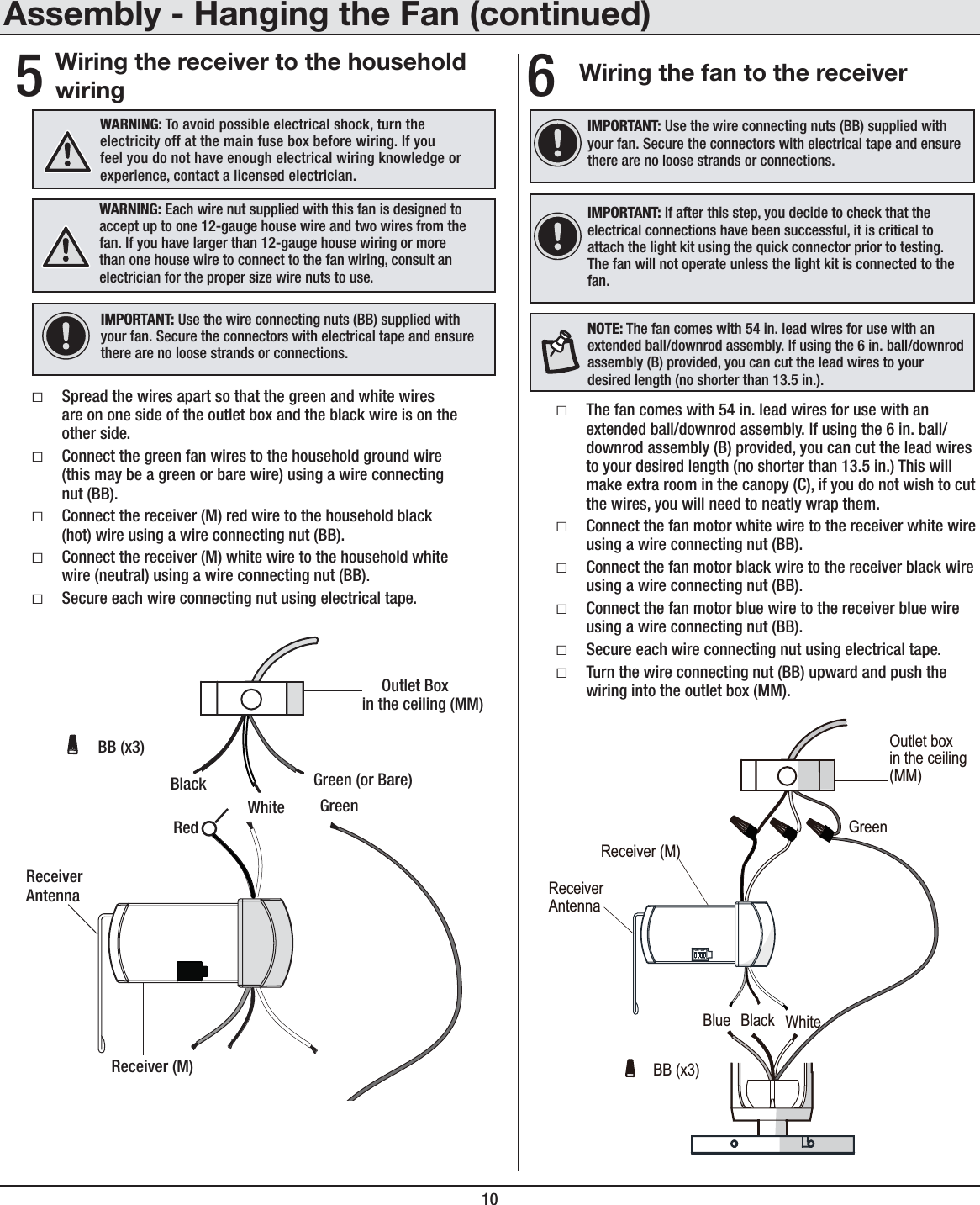
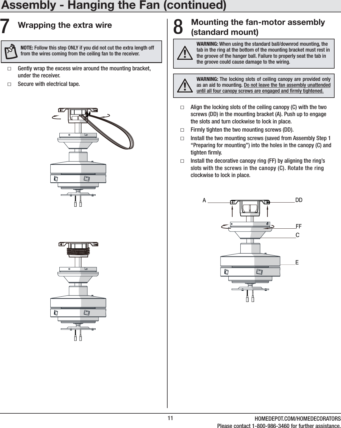
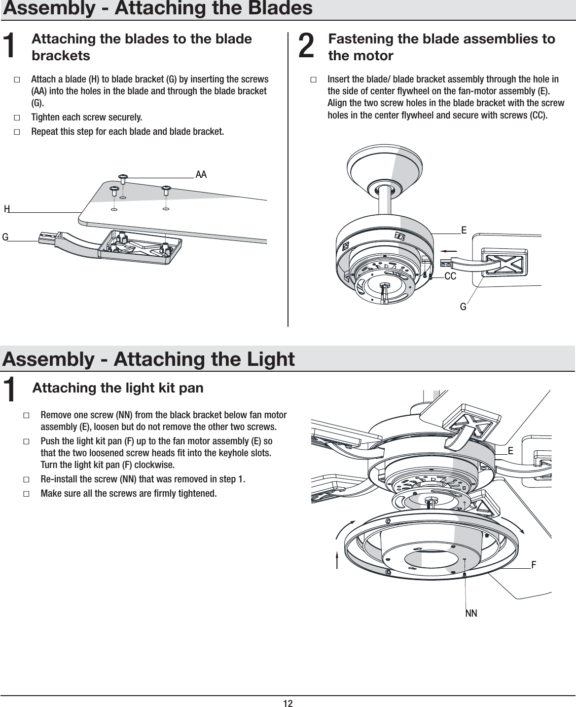
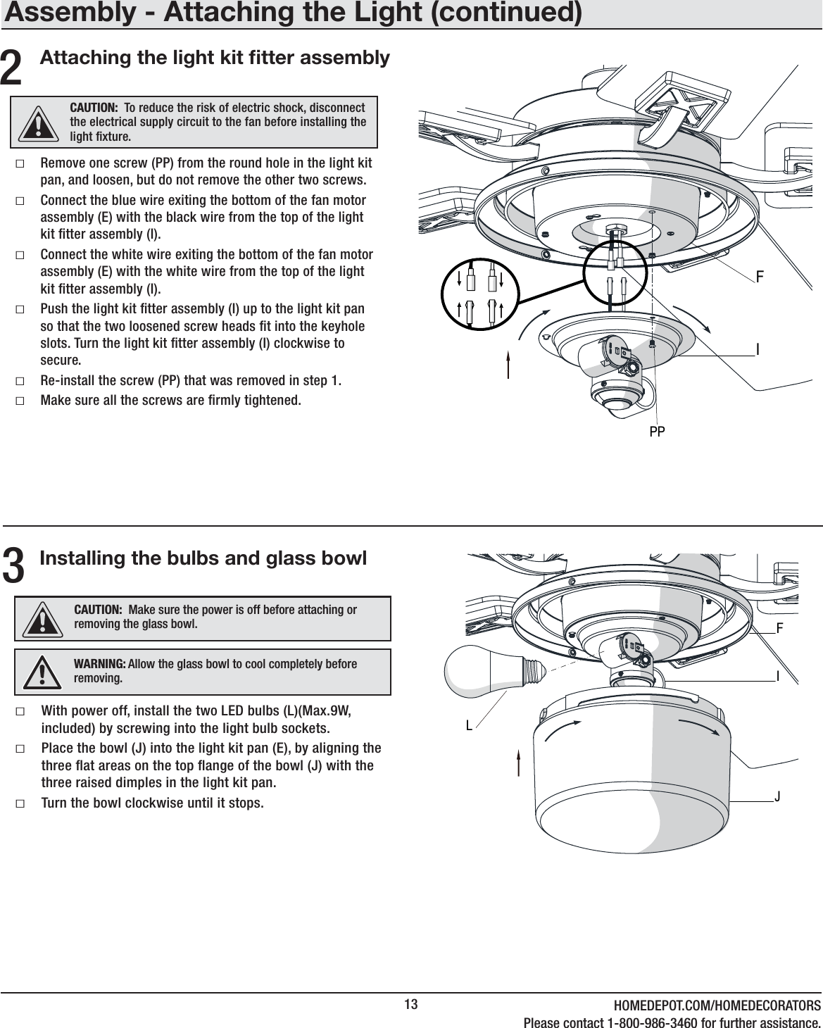
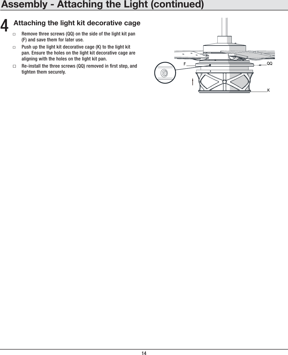
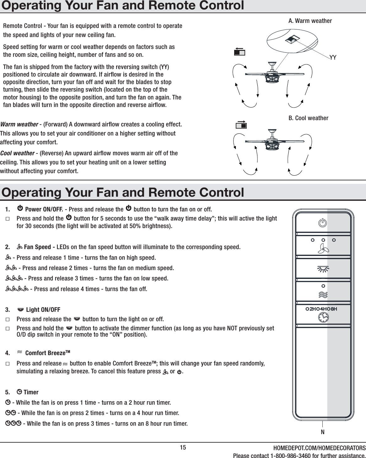

![10Ensamblaje - Cómo colgar el ventilador (continuación)5Cómo conectar los cables del receptor a los cables del hogarIMPORTANTE: Usa las tuercas de conexión de cables (BB) incluidas con tu ventilador. Sujeta los conectores con cinta de electricista y asegura que no haya conexiones ni cables sueltos.ADVERTENCIA: Cada tuerca para cable suministrada con este ventilador está diseñada para aceptar hasta un cable doméstico de calibre 12 y dos cables del ventilador. Si tienes un cableado doméstico que exceda del calibre 12 o más de un cable doméstico para conectar al cableado del ventilador, consulta a un electricista para el tamaño adecuado de las tuercas para cables a usar.ƑSepara los cables de manera que el verde y el blanco queden de un lado de la caja eléctrica y el negro quede del otro lado. ƑConecta los cables verdes del ventilador al cable con conexión a tierra de la casa (este puede ser verde o pelado) con una tuerca de conexión de cables (BB).ƑConecta el cable rojo del receptor (M) al cable negro del hogar (positivo), usando una tuerca de conexión de cables (BB).ƑConecta el cable blanco del receptor (M) al cable blanco del hogar (neutro), usando una tuerca de conexión de cables (BB).ƑAsegura cada tuerca de conexión de cables con cinta de electricista.RojoNegroVerde (o pelado)VerdeCaja eléctricaen el techo (MM)AntenareceptoraBlancoReceptor (M)BB (x3)1234ON DIPADVERTENCIA: Para evitar una posible descarga eléctrica, corta la electricidad en la caja principal de fusibles antes del cableado. Si crees que no tienes suciente conocimiento o experiencia sobre cableado eléctrico, contacta a un electricista certicado.Cómo conectar los cables del ventilador al receptorƑEl ventilador viene con cables terminales de 1.37 m para usar con un ensamblaje extendido de tubo bajante/bola. Si usas el ensamblaje de tubo bajante/bola (B) de 15.2 cm (6 plg) incluido, puedes recortar los cables terminales al largo deseado [no menos de 34.3 cm (13.5 plg)]. Esto dejará más espacio en la cubierta (C). Si no quieres cortar los cables, deberás enrollarlos cuidadosamente. ƑConecta el cable blanco del motor del ventilador al cable blanco del receptor usando una tuerca de conexión de cables (BB).ƑConecta el cable negro del motor del ventilador al cable negro del receptor usando una tuerca de conexión de cables (BB).ƑConecta el cable azul del motor del ventilador al cable azul del receptor usando una tuerca de conexión de cables (BB).ƑAsegura cada tuerca de conexión de cables con cinta de electricista. ƑGira la tuerca de conexión de cables (BB) hacia arriba y coloca el cableado dentro de la caja eléctrica (MM).6IMPORTANTE:Usa las tuercas de conexión de cables (BB) incluidas con tu ventilador. Sujeta los conectores con cinta de electricista y asegura que no haya conexiones ni cables sueltos.NOTA: El ventilador viene con cables terminales de 1.37 m para usar con un ensamblaje extendido de tubo bajante/bola. Si usas el ensamblaje de tubo bajante/bola (B) de 15.2 cm (6 plg) incluido, puedes recortar los cables terminales al largo deseado [no menos de 34.3 cm (13.5 plg)].IMPORTANTE:Si luego de este paso decides comprobar si las conexiones se establecieron exitosamente, es fundamental instalar el kit de luces usando el conector rápido antes de proceder a la comprobación. El ventilador funcionará sólo si el kit de luces está conectado al ventilador.Caja eléctricaen el techo(MM)Receptor (M)AzulAntenareceptoraNegro BlancoVerdeBB (x3)1234ON DIP](https://usermanual.wiki/King-of-Fans/52GLHS/User-Guide-2845334-Page-27.png)