Kingwave Technology 6900 2.4GHz Long Range Wireless LAN Access Point/Bridge User Manual
Kingwave Technology Co., Ltd. 2.4GHz Long Range Wireless LAN Access Point/Bridge Users Manual
Users Manual
6900 Series
2.4GHz Long Range Wireless LAN Access Point / Bridge
Installation and Operation
Manual
Ver 1.0
August, 2005

1
PROFESSIONAL INSTALLATION REQUIRED
The 6900 Series must be installed as a system by experienced antenna installation professionals who
are familiar with Radio Frequency (RF) issues such as gains and losses, as well as local building and
safety codes. Failure to do so will void the product warranty and may expose the end user to excessive
RF hazard.
Regulations regarding maximum antenna gains, power output and maximum permissible exposure
vary from country to country. It is the responsibility of the end user to operate within the limits of these
regulations and to ensure that the professional installers who install this device are aware of these
regulations. All antennas are intended to be installed outdoors.
MICROWAVE RADIO RADIATION WARNING
When installed properly, the 6900 Series radio equipment complies with the limits for human exposure
to radio frequency (RF) fields adopted by the Federal Communications Commission (FCC). All
KINGWAVE microwave radio equipment is designed so that under normal working conditions,
microwave radiation directly from the radio is negligible when compared with the permissible limit of
continuous daily exposure recommended in the United States by ANSI/IEEE C95.1-1991 (R1997), Safety
Levels with Respect to Human Exposure to Radio Frequency Electromagnetic Fields, 3 kHz to 300 GHz.
Microwave signal levels that give rise to hazardous radiation levels can exist within transmitter power
amplifiers, associated RF multiplexers, and antenna systems. Do not disconnect RF coaxial connectors,
open microwave units, or break down any microwave screening while the radio equipment is operating.
Federal Communication Commission Interference Statement
This equipment
has been
tested and found to
comply with
the limits for
a Class B digital
device,
pursuant
to Part 15
of
FCC Rules. These limits are designed
to provide reasonable
protection against harmful
interference
in a residential installation. This
equipment generates, uses, and can radiate radio frequency
energy and, if
not installed and used in
accordance
with
the instructions,
may cause harmful interference
to radio communications. However,
there is
no guarantee that interference
will
not occur in a
particular
installation. If this
equipment does cause harmful interference
to radio
or
television reception,
which
can
be determined by turning the equipment off and on,
the user
is
encouraged to try to correct the
interference
by one or more
of
the following measures:
1.
Reorient or
relocate the
receiving antenna.
2.
Increase the separation
between
the equipment and receiver.
3.
Connect the equipment into
an outlet on a circuit different from
that to which the receiver is
connected.
4.
Consult the dealer or an experienced radio technician for help.
2
FCC Caution
This
device and its antenna must not
be co-located or operating
in conjunction with any other
antenna
or transmitter.
This
device complies
with Part 15
of the
FCC Rules. Operation is
subject to the following
two
conditions:
(1) this device may
not
cause harmful interference, and
(2) this
device
must accept any interference
received,
including
interference that may cause undesired
operation.
Any
changes
or modifications
not expressly
approved by the party responsible for compliance could
void
the authority to operate
equipment.
Federal Communications Commission (FCC) Radiation
Exposure
Statement
This equipment complies with FCC radiation exposure limits set forth for an uncontrolled environment. This
equipment should be installed and operated with minimum distance 20cm between the radiator & your body.
Federal Communications Commission (FCC) RF Exposure
Requirements
SAR compliance
has been
established
in the
laptop computer(s) configurations
with PCMCIA slot on
the
side near the center, as
tested in
the application for Certification, and can
be
used
in laptop
computer(s) with
substantially
similar physical dimensions, construction, and electrical and RF characteristics. Use in other
devices such
a PDAs or
lappads is not authorized.
This transmitter is restricted for use
with the
specific
antenna(s)
tested in the application for Certification.
The antenna(s) used for this transmitter
must not
be
co-located or
operating in conjunction with
any
other antenna or transmitter.
These products are
labeled with
one of
the
following FCC ID numbers
FCC ID:TJI-6900
3
Table of Contents
PROFESSIONAL INSTALLATION REQUIRED........................................................
1
MICROWAVE RADIO RADIATION WARNING ........................................................ 1
Federal Communications Commission
(FCC) Interference Statement
............... 1
Table of Contents..................................................................................................... 3
Chapter 1 Overview ..................................................................................................
4
1.1 Introduction to the 6900 Series.................................................................................................... 4
1.2
Features & Benefits
.................................................................................................................... 4
1.3 Applications of the 6900 Series................................................................................................... 5
1.4 The 6900 series product types...................................................................................................... 8
1.5 The 6900 series Package Contents............................................................................................... 9
Chapter 2 Hardware Installation
............................................................................. 10
2.1 Hardware Description ................................................................................................................. 10
2.2 Outdoor Unit Installation............................................................................................................. 11
2.3 Mounting Bracket on Mast with /U-bolts..................................................................................... 13
2.4 Indoor Unit Installation.............................................................................................................. 14
Chapter 3 Quick Start-First time use.......................................................................14
3.1 Typical Deployment of 6900 Series in a Point-to-Point Configuration.......................................14
3.2
To set the Base station unit (BU)
...............................................................................................15
3.3
To set the Remote unit (RU)
............................................... ......................................................18
3.4 Running Test................................................................................................................................ 22
Chapter 4 Choosing a Mounting Location..............................................................
24
4.1 Antenna Polarization.................................................................................................................... 24
4.2 Antenna Radiation Angle............................................................................................................. 25
4.3 Signal Path Clearance (Fresnel zone) .........................................................................................25
4.4 Multi-Path Fading........................................................................................................................ 26
4.5 Relationship between data rate and distance............................................................................... 26
Appendix A –6900 Series Technical Specifications………………………………….
27
Appendix B –6900 Series Access Point /Bridge Configuration……………………28
4
Chapter 1 Overview
1.1 Introduction to the 6900 Series
The
6900 Series
is a powerful answer for customers seeking a reliable high- speed wireless
connectivity solution.
It is
a
2.4GHz
IEEE
802.11b/g-compliant
Wireless Bridge/AP/AP Client, data
delivers 1 to 54 Mbps data rates without the need for a license.
6900 Series can operate as a
point-to-point or a
point-to-multipoint
bridge
to
link
networks in
different
buildings.
6900 Series is
particularly suited for financial banks, campus, store merchants and small business owners
to create wireless backbone networks.
System privacy is inherent through the MAC & 802.1x based
mutual authentication functionality by preventing unauthorized intrusion to the radio link.
The 6900 Series is designed for outdoor environments.
With lift-cover watertight
housing,
this
is
a
robust
Bridge/AP/AP Client, and
uniquely designed
that Antenna to integrate with housing.
Supplying
the power and Ethernet connectivity concurrently via a single Ethernet cable, the power over
Ethernet (POE) technology makes quick outdoor installation.
6900 Series
achieves rapid Return On
Investment (ROI) for inter-building connection compared to T1 leased line with high capacity and high
data throughput.
The
6900 Series
is intended for professional
installation
only.
This
manual,
however, is also
designed for personnel
who
plan, operate and administrate the
6900 Series
communication system.
Please review
the
entire manual before powering
up or deploying
any
6900 Series
.
1.2
Features & Benefits
Features
Benefits
Point-to-Point/ Point-to-Multipoint
Wireless Connectivity Lets users transfer information between two buildings or
multiple buildings across the area
Watertight and Weatherproof Avoid water invaded and weather corroded
The Antenna to integrate with the Housing To set up easily
64 /128-bit WEP Data Encryption Powerful data security
Hide SSID (AP Mode) Avoids unallowable users sharing bandwidth, increases
efficiency of the network
DHCP Client/ Server Simplifies network administration
MAC Address Filtering (AP Mode) Ensures secure network connection
Power Amplifier Upgradeable Flexibility and cost-effective
Power over Ethernet (POE) Easy installation and cost-effective
Web-based Configuration Helps administrators to remotely configure or manage the
Bridge with web browser

5
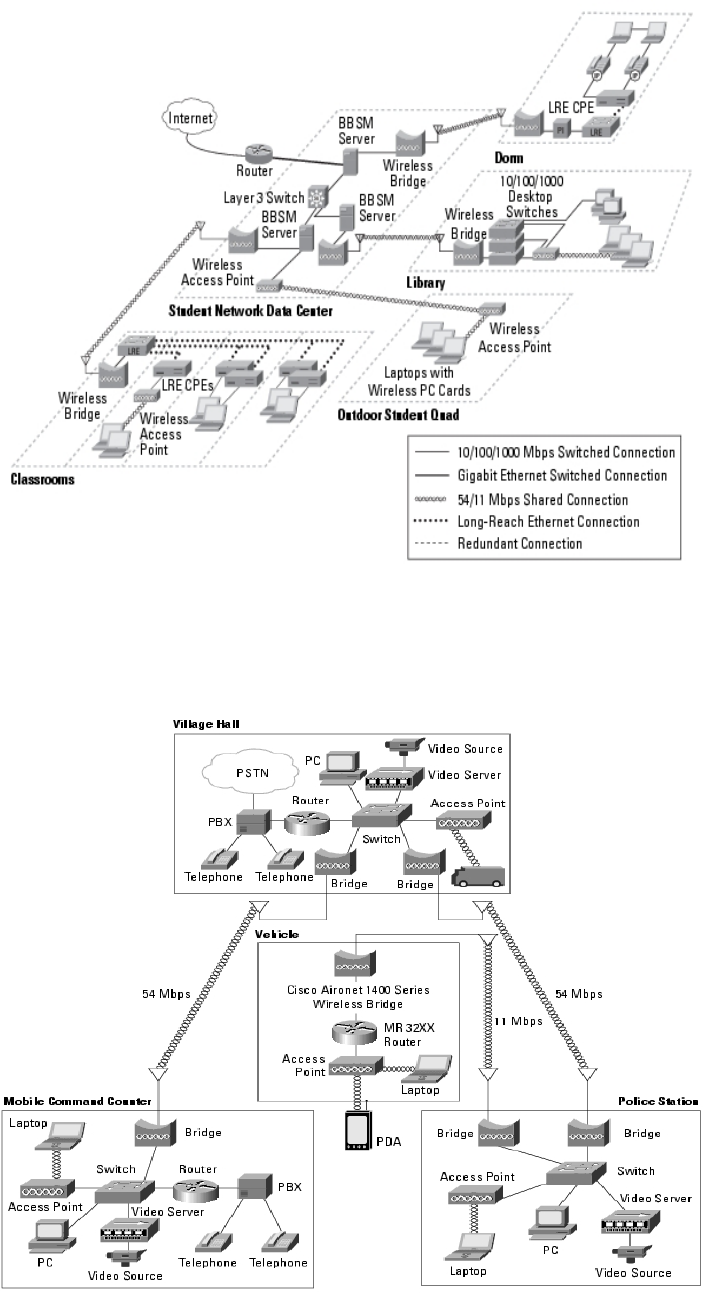
1.3 Applications of the 6900 Series
The 6900 Series is designed to
serve the following communications markets:
◎ Central office to branch office(s) connection
◎Medical hospitals and Medical hospitals wireless connection
6
◎ Education schools and Universities inter-building connection
◎ Public-Safety Network

7
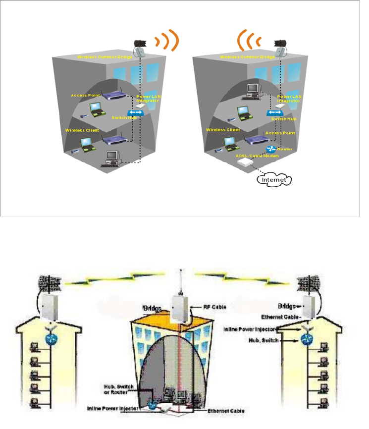
◎ Building to building connection
8
1.4 The 6900 series operation types
There are two different modes in which you can set
up the 6900 series
in the building-to-building
wireless network: Point to Point mode, and Point
to Multipoint mode.
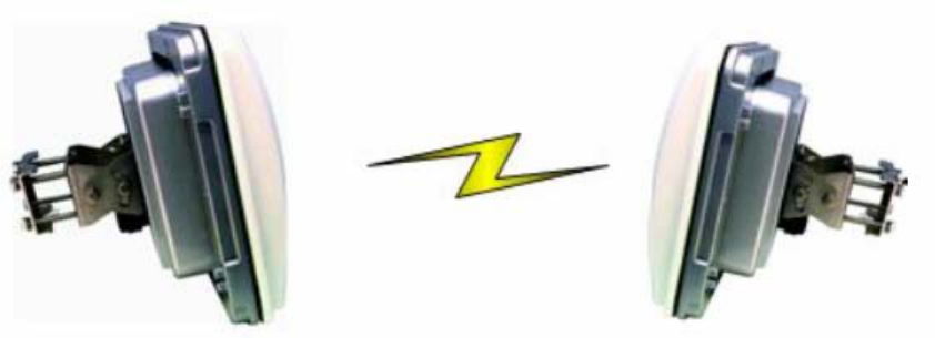
◎
Point-to-Point Connectivity (PTP Mode)
This is the simplest network configuration in which several computers equipped with the PC cards
or client bridges that form
a wireless network whenever they are within range of one another.
◎
Point-to-Multi point Connectivity(PTMP mode)
9
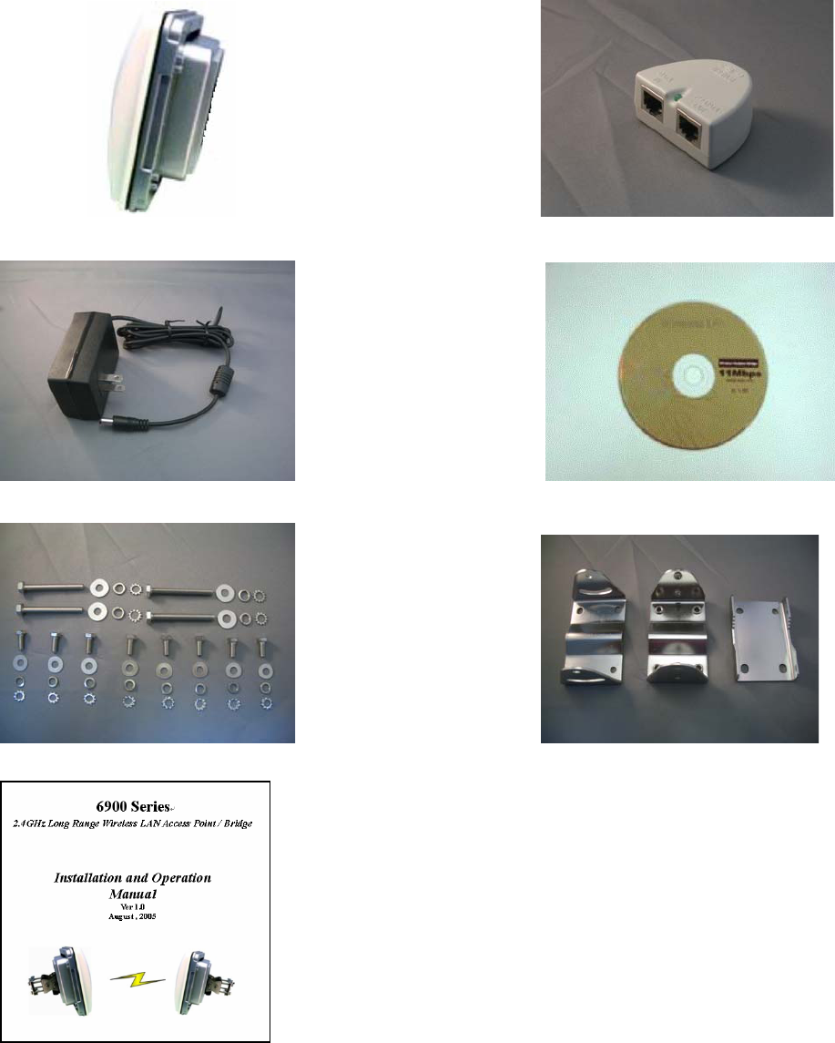
1.5 The 6900 series Package Content
Open the
package carefully, and
make sure that none of the items listed below are missing. Do not
discard the packing materials, in case of return; the device must be shipped in
its original package.
Outdoor unit DC injector
48Vdc power Adapter Installation CD
Screws Mounting Kit
Installation and Operation Manual
10
Chapter 2 Hardware Installation
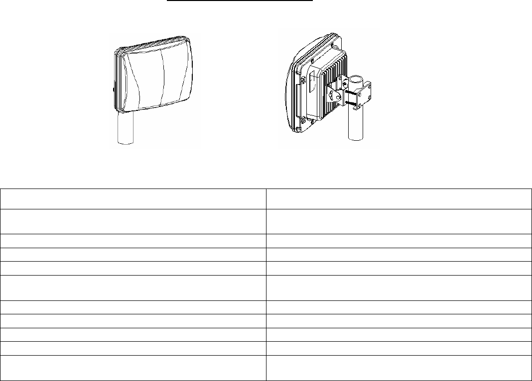
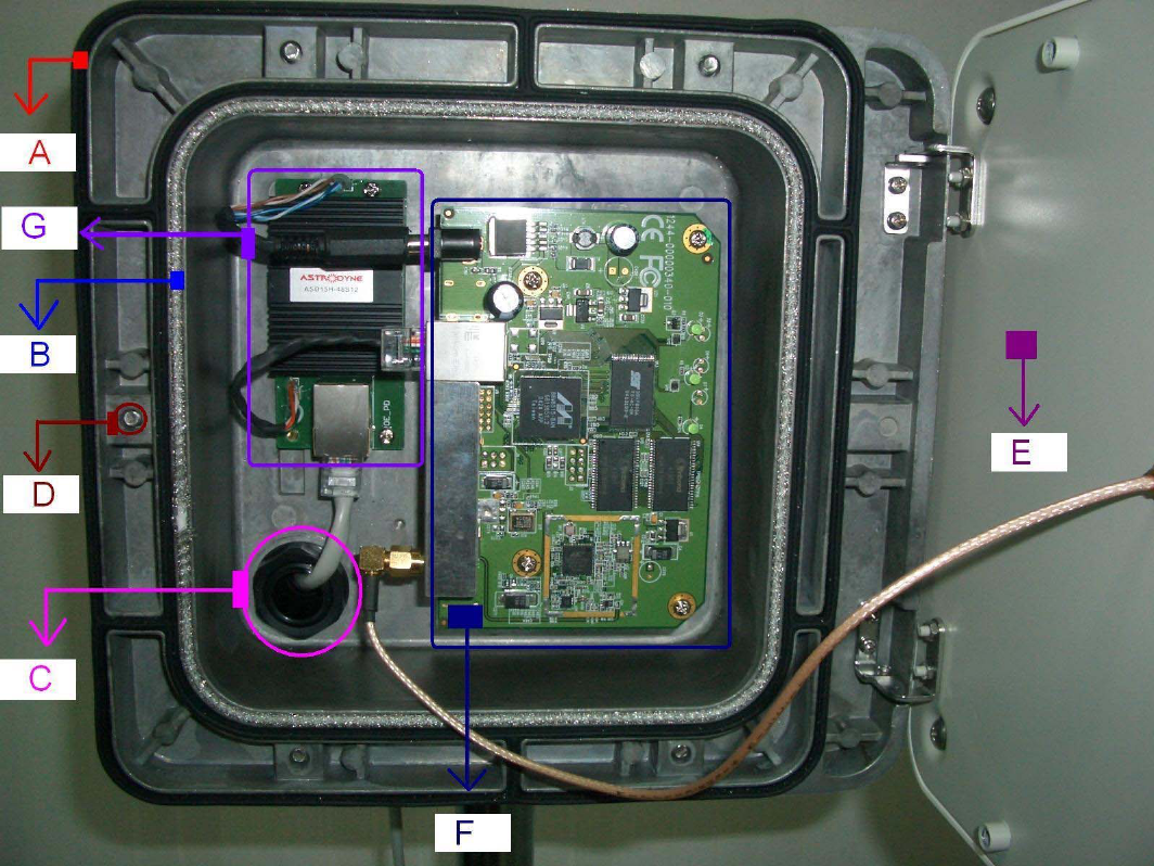
2.1 Hardware Description
◎
Outdoor unit
A. Two layers silica gel: having
double-waterproof
B.
EMI prevent wire: To
avoid electromagnetic interference
C.
Nylon cable gland:IP68;Working Temp:-40
℃
~100
℃
D.
Half-screw: Not to fall
E.
Panel Antenna:14dBi or 17 dBi gain;SMA connector
F.
Access Point/Bridge:IEEE
802.11b/g-compliant
G.
Power over ethernet(POE) Splitter set: Output 12vdc/1.2A
H.
Power Amplifier
module:30dBm(1W) or 33dBm(2W) output
I. Mounting kit: Mounting Bracket on Mast with /U-bolts
☆LED on the AP/Bridge description:
On the
AP/Bridge
there are LED lights that inform you of the
AP/Bridge
’s current status. Below
is an explanation of each LED.
11
LED
Color
Status
Description
Power
Green
On
Off
Power is supplied
No
Power.
Wireless
Activity
Green
Flash
Off
Antenna is transmitting or receiving data.
Antenna is not transmitting or receiving data
LAN
Link/Activity
Green
Green
On
Flash
Off
A valid link is established
It is transmitting or receiving data
No link is established
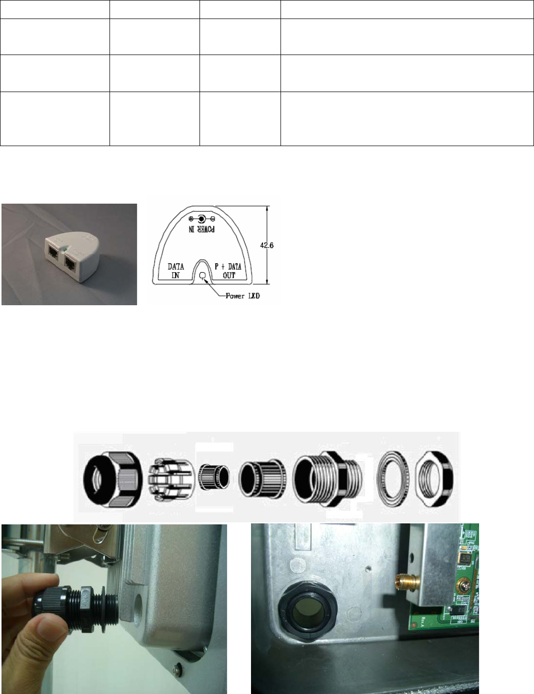
◎
Indoor unit
DC injector
A. Power LED: The Light is green.
Power is supplied
B.
DATA IN:TO connect PC/Notebook or network
C.
P+DATA OUT: TO connect 6900 series outdoor unit
D.
Power in: TO connect 48vdc adapter
2.2 Outdoor Unit Installation
Step 1: Ethernet cable to pass through “
Nylon cable gland”
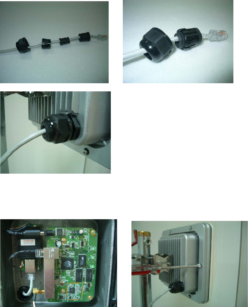
12
Step 2: Ethernet cable to connect POE
Splitter set
Step 3:
POE
Splitter set to connect AP/Bridge
Step 4: Antenna to connect AP/Bridge Step 5: To screw the housing
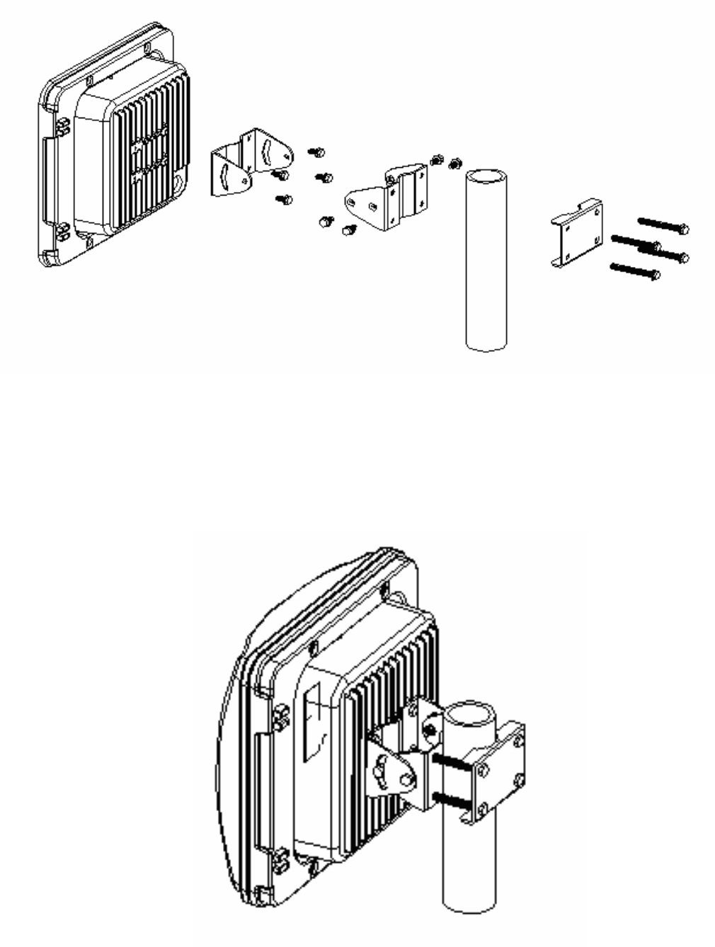
13
2.3 Mounting Bracket on Mast with /U-bolts
Step 1: To fix pole mounting bracket
Step 2: To fix pivot adapter bracket
Step 3: To fix pole clamp
Step 4: To adjust the angles
14
2.4 Indoor Unit Installation
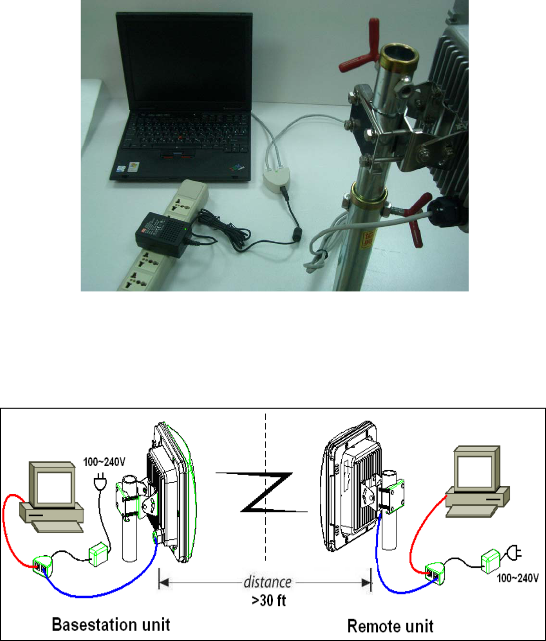
Chapter 3 Quick Start - First time use
3.1 Typical Deployment of 6900 Series in a
Point-to-Point Configuration
15
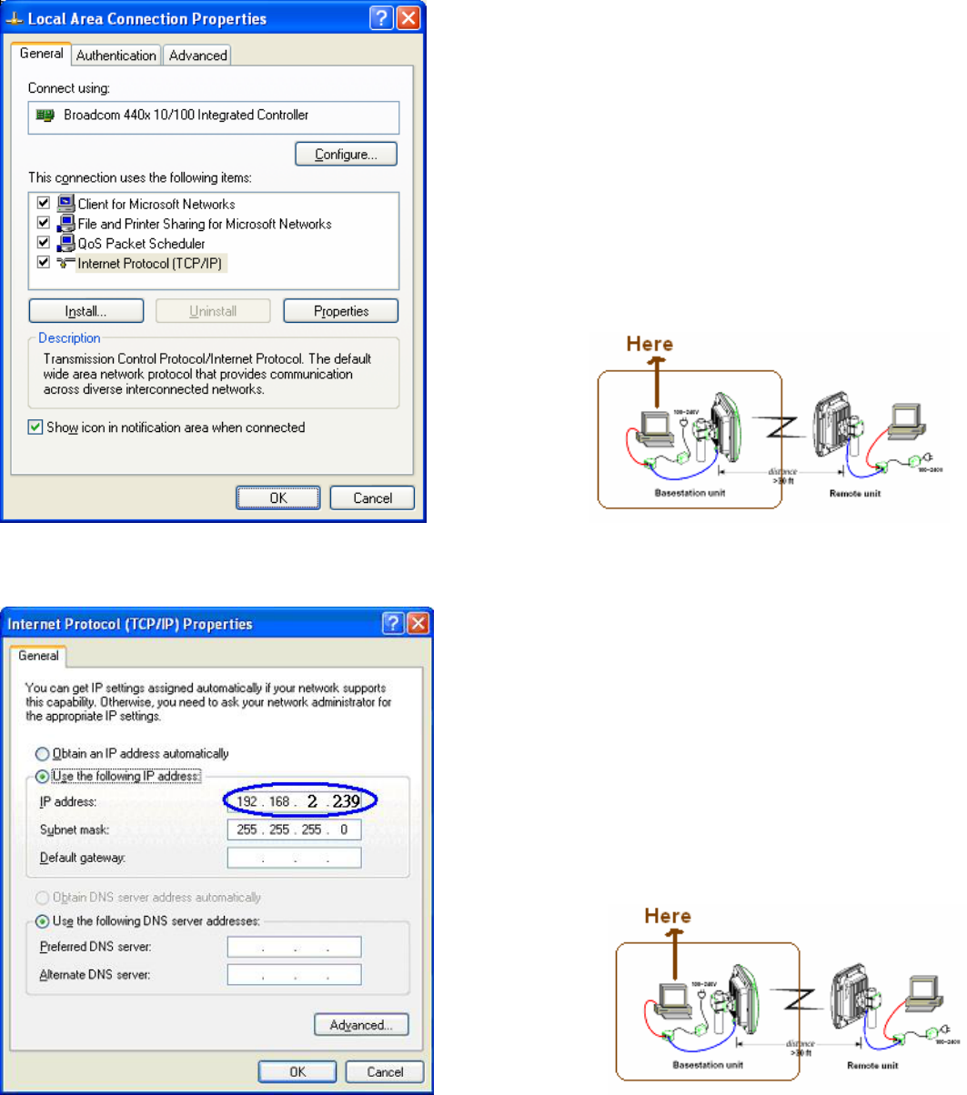
3.2 To set the Base Station unit (BU)
PC Configuration
Follow the steps below in order to configure the
TCP/IP settings of your PC.
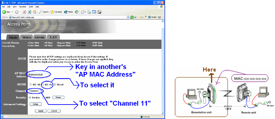
Step 1. In the Control Panel double click
Network Connections
, and then double click on the
connection of your Network Interface Card (NIC). You will then see the following screen.
Step 2.
Select
Internet Protocol (TCP/IP)
and then click on the
Properties
button. This will allow
you to configure the IP address
of your PC. You will then
see the following screen.
16
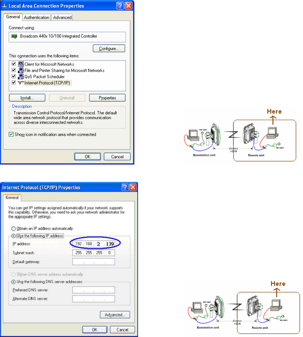
Step 3.
Select
Use the following IP address
radio
button, and then enter an IP address and
subnet mask for your PC. Make sure that the device and your PC is on the same subnet.
Step 4.
Click on the
OK
button, your PC’s
TCP/IP settings have been configured.
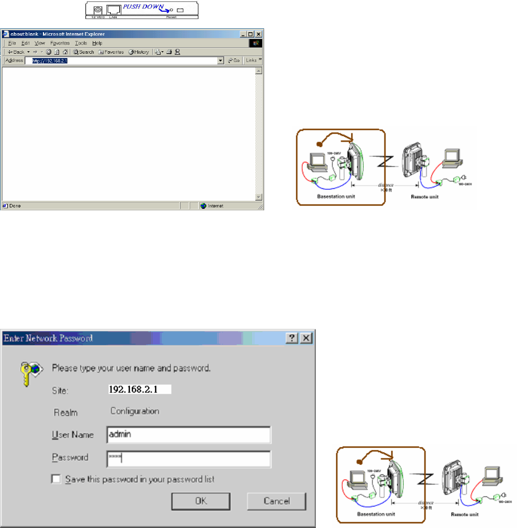
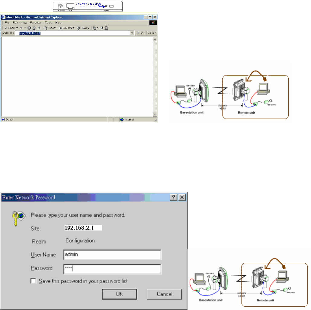
Bridge Setup-Web Configuration
Step 5. Logging
In
To configure the Bridge through the web-browser, enter the IP address
of the Bridge into the
address bar of the web-browser (default IP:
192.168.2.1
), and press
Enter
. If it cannot work,
pleas press the reset button which is on AP/Bridge. Please see the reference of the enclosed
picture.
Step 6.
A screen will be popped up and request you to enter user name and password. The
default user name and password is as follows.
User Name: Admin
Password: 1234
Enter the default user name and password, then press
OK
button directly.
17
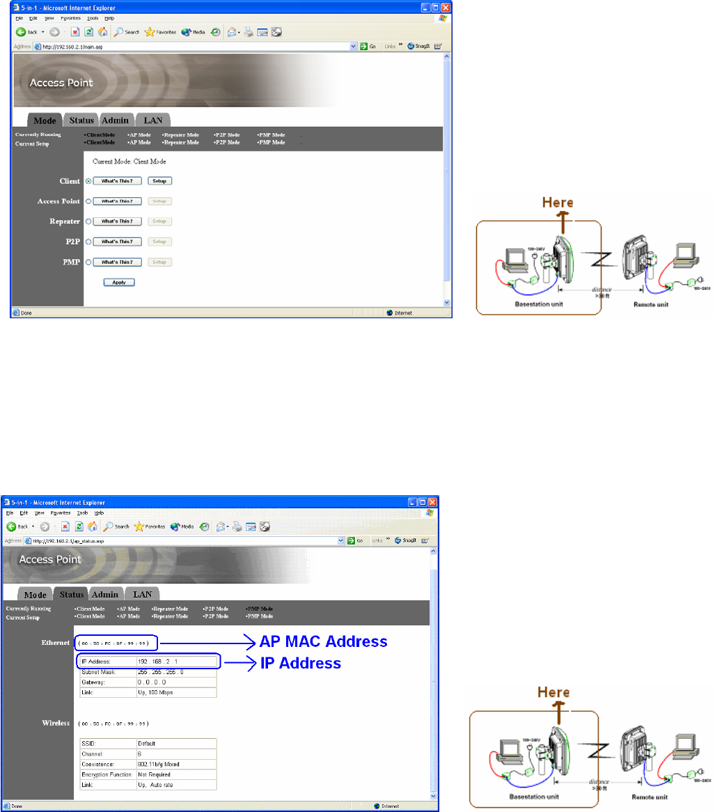
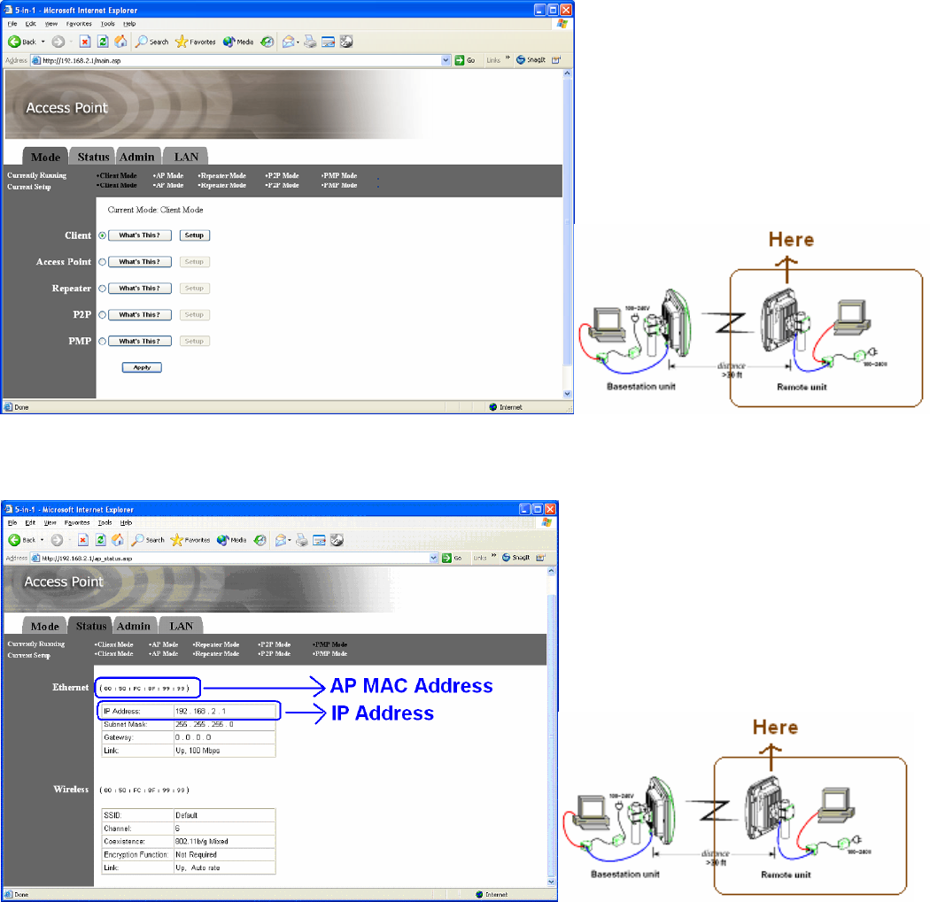
Step 7. After you login, you will see the following screen.
Step 8. Search Status
Choose the item-Status.
After this step, you will see the following screen,
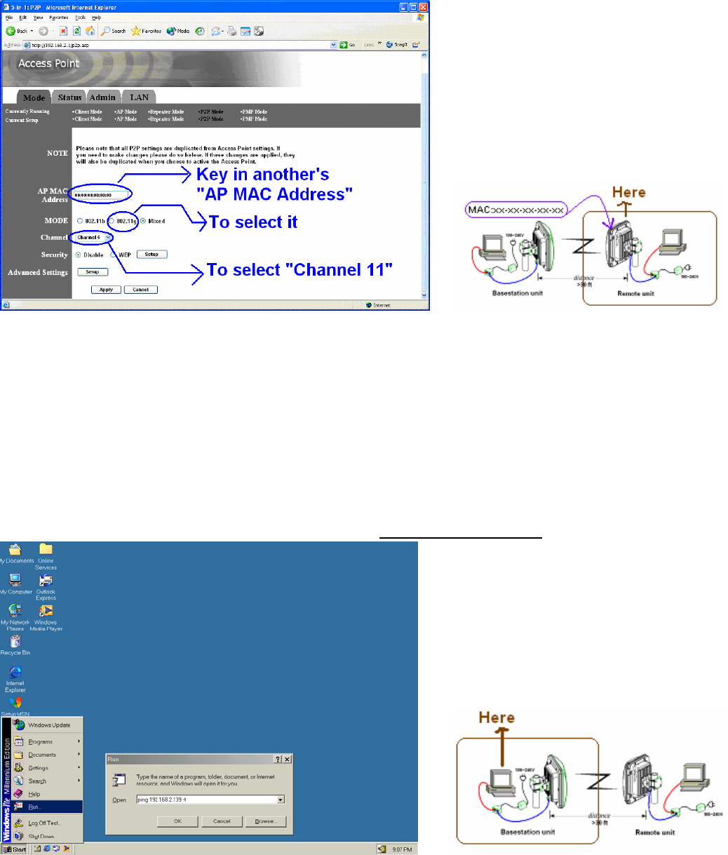
Step 9. To set P2P (point to point) mode
to select “Mode”->”P2P”
.After you do, you will see the following screen.
18
Step 10. Please key-in the number of Remote unit (RU) to the column of AP MAC Address.
If you don’t know the values, please look for the 3.3 (set the RU), to run step 8, then to
search the number.
Step 11. To choose 802.11g of Mode column.
Step 12 To change the values of channel to 11.
3.3 To set the Remote unit (RU)
PC Configuration
Follow the steps below in order to configure the
TCP/IP settings of your PC.
Step 1. In the Control Panel double click
Network Connections
, and then double click on the
connection of your Network Interface Card (NIC). You will then see the following screen.
19
Step 2.
Select
Internet Protocol (TCP/IP)
and then click on the
Properties
button. This will allow
you to configure the IP address
of your PC. You will then
see the following screen.
Step 3.
Select
Use the following IP address
radio
button, and then enter an IP address and
subnet mask for your PC. Make sure that the device and your PC is on the same subnet.
Step 4.
Click on the
OK
button, your PC’s
TCP/IP settings have been configured.
Bridge Setup-Web Configuration
20
Step 5. Logging
In
To configure the Bridge through the web-browser, enter the IP address
of the Bridge into the
address bar of the web-browser (default IP:
192.168.2.1
), and press
Enter
. If it cannot work,
pleas press the reset button which is on AP/Bridge. Please see the reference of the enclosed
picture.
Step 6.
A screen will be popped up and request you to enter user name and password. The
default user name and password is as follows.
User Name: Admin
Password: 1234
Enter the default user name and password, then press
OK
button directly.
Step 7. After you login, you will see the following screen.
21
Step 8. Search Status
Choose the item-Status.
After this step, you will see the following screen,
Step 9. To set P2P (point to point) mode
to select “Mode”->”P2P”
.After you do, you will see the following screen.
22
Step 10. Please key-in the number of Base station unit (BU) to the column of AP MAC Address.
If you don’t know the values, please look for the 3.2 (set the BU), to run step 8, then to
search the number.
Step 11. To choose 802.11g of Mode column.
Step 12 To change the values of channel to 11.
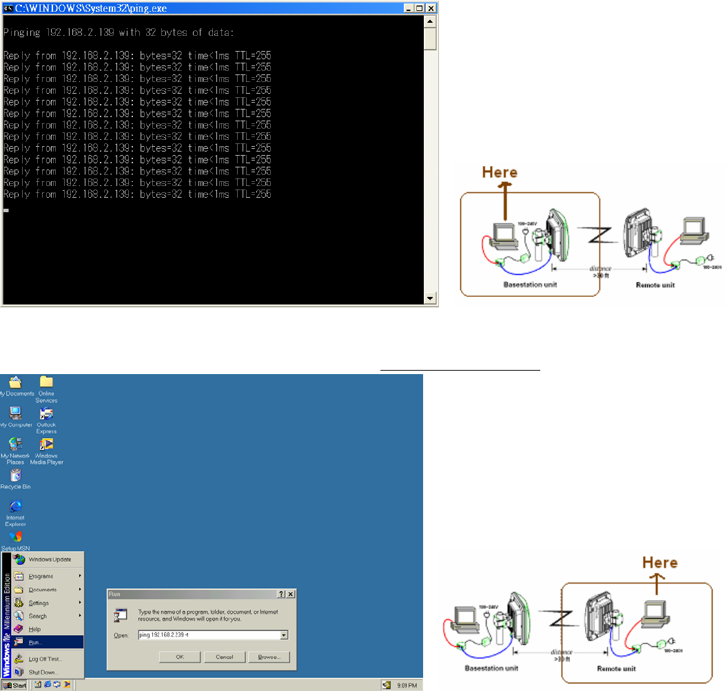
3.4 Running Test
Step 1. To link PC which is in Remote unit (RU).
On PC which is in Base station (BU), RUN ping 192.168.2.139 –t
After this step, you will see the following screen,
23
Step 2 To link PC which is in Base station unit (BU).
On PC which is in Remote unit (RU), RUN ping 192.168.2.239 –t
After this step, you will see the following screen,
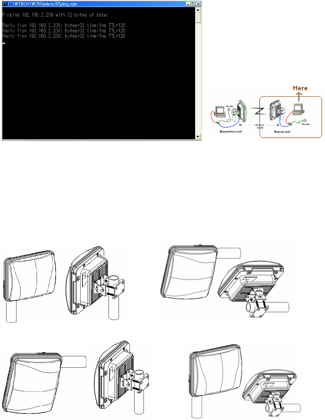
24
Step3 If step1&step 2 worked, it means that Base station unit (BU) and Remote unit (RU)
constructed the wireless LAN
Step 4 If step1&step2 do not work, please see the reference of chapter 3&4, then redo the step1~2
Chapter 4 Choosing a Mounting Location
4.1 Antenna Polarization
The integrated antenna radiates and receives vertically polarized radio signals. Polarization helps
reduce interference because the antenna tends to reject cross-polarized signals from other
sources.
a. Polarization is the same. (Correct)
Good Good
b. Polarization is different. (No correct)
Bad Bad
25
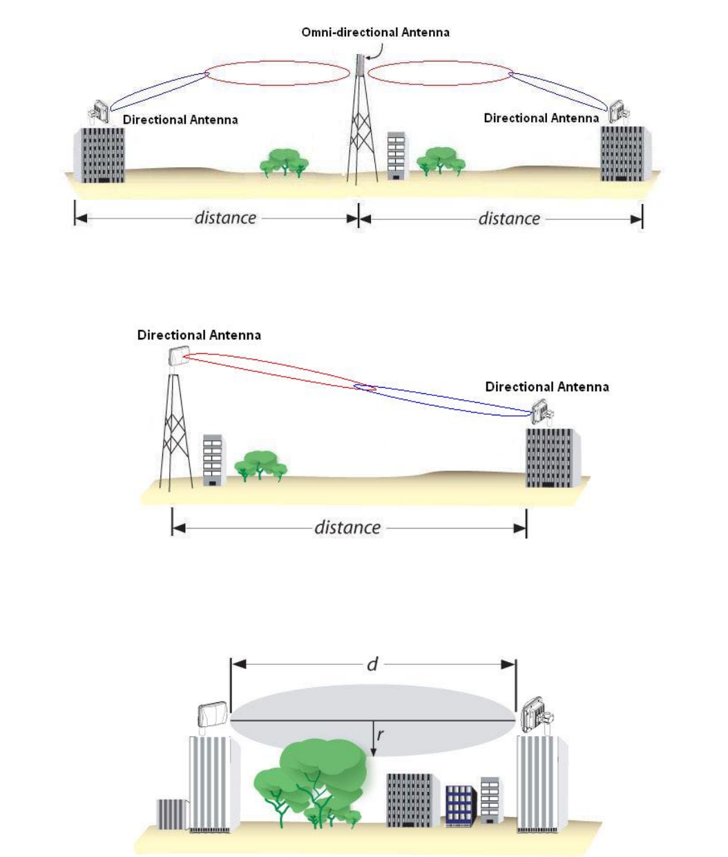
4.2 Antenna Radiation Angle
The range of Antenna Radiation has angles, not all around.
4.3 Signal Path Clearance (Fresnel Zone)
The Fresnel Zone is the area around the visual line-of-sight that radio waves spread out into
after they leave the antenna. You want a clear line of sight to maintain signal strength,
especially for 2.4 GHz wireless systems.
26
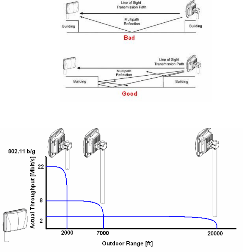
4.4 Multi-Path Fading
Because a 6900 Series typically transmits its strongest signals in a
cone-shaped pattern,
some of the signal
may be reflected from a nearby building, from water under the signal path,
or from other
RF
reflectors.
This reflected
signal can then be received
by the far- end 6900
series and superimposed on the main
signal, usually degrading the signal strength.
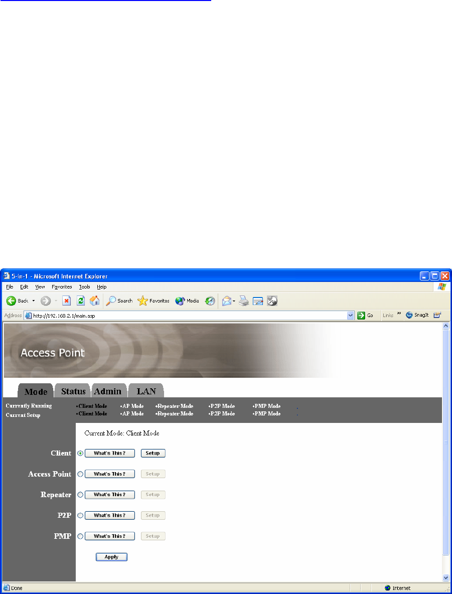
4.5 Relationship between data rate and distance
With increasing of distance, data rate (throughput) will decrease.

27
Appendix A –6900 Series Technical Specifications
Item 6919 6917
Antenna 14dBi 17dBi
Standards Wireless
interface IEEE802.11b/g
Modulation OFDM with BPSK, QPSK 16AM, 64QAM (11g)
BPSK, QPSK, CCK (11b)
Wired Interface 100 base T (RJ-45)
Frequency Band 2400 ~ 2483.5MHz (Industrial Scientific Medical Band)
Radio Technology DSSS/OFDM
Data Rate 54/48/36/24/18/12/11/9/6/5.5/2/1 Mbps auto fallback
Security 64/128-bit WEP Encryption
RF Transmission
power
Type A Output Power 2 WATTS (+33dBm)
Type B Output Power 1 WATT (+30dBm)
Sensitivity -70dBm @ 54Mbps
Power Supply DC48V/0.38A, 100V-240V for AC adaptor
Operating
Temperature -20°C ~ +70°C
Operating Humidity 0-90% (Non-condensing)
Certification FCC (1 watts only)
Dimensions H210*W220*D120m/m H260*W260*D100m/m
Weight 1.7Kg 2.8Kg
28
Appendix B – 6900 Series Access Point /Bridge
Configuration
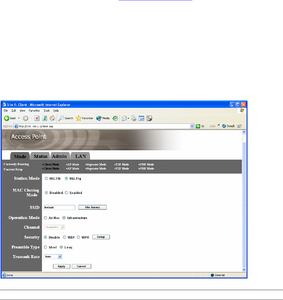
Configuring the Access Point
This Access Point supports Client, AP, Repeater and Bridge modes. “Client Mode” is used to let a network
device with only wired Ethernet function to have wireless LAN communication capability. It provides both
Ad Hoc and Infrastructure modes for the “Station Mode”. With “Station-Ad Hoc mode”, it can let your
network device join a wireless LAN with peer-to-peer communication. With “Station-Infrastructure mode”, it
can let your network device join a wireless LAN through an access point. “AP Mode” provides pure access
point function. The simplest way to build up a wireless LAN is to use “AP Mode”. If you want a repeater to
bridge with another reapter and provide connection service for other wireless station at the same time, you
have to set the access point to “Repeater mode”. You can use two access points with “P2P mode” to bridge
two wired Ethernet networks together. If you want to bridge more than two wired Ethernet networks together,
you have to use enough access points with “PMP mode”. An access point with “P2P mode” or “PMP mode”
can only be used to bridge wired Ethernet networks together. It can’t accept connection from other wireless
station at the same time.
29
Client Mode configuration
It is used to let a network device with only wired Ethernet function to have wireless LAN
communication capability. It provides both Ad Hoc and Infrastructure modes for the “Client
Mode”. With “Ad Hoc mode”, it can let your network device join a wireless LAN with
peer-to-peer communication. With “Infrastructure mode”, it can let your network device join
a wireless LAN through an access point.
Parameter Description
Station Mode 802.11b mode: It allows to select the transmit rate up to 11Mbps
802.11g mode: It allows to select the transmit rate up to 54Mbps
MAC Cloning Mode Disabled: It will use it’s own MAC address to access the wireless LAN.
Enabled: It will use PC’s MAC address to access the wireless LAN.
SSID The SSID (up to 32 printable ASCII characters) is the unique name
identified in a WLAN. The ID prevents the unintentional merging of two
co-located WLANs. Please make sure that the SSID of all stations in the
same WLAN network are the same. The default SSID is “default”.
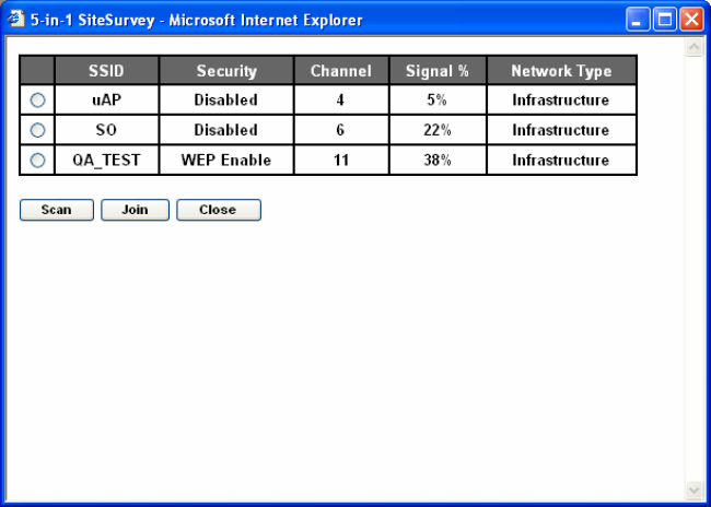
Site Survey Click “Site Survey” button, then a “Wireless Site Survey Table” will pop up.
It will list all available access points near by. You can select one access
point in the table and it will join wireless LAN through this access point.
Operation Mode AD-Hoc: It can let your network device join a wireless LAN with
peer-to-peer communication.
Infrastructure: It can let your network device join a wireless LAN
30
through an access point.
Channel Select the appropriate channel from the list provided to correspond with
your network settings. Channels differ from country to country.
Channel 1-11 (North America)
Channel 1-14 (Japan)
Channel 1-13 (Europe)
There are 14 channels available.
Security Disable: Disable the security function.
WEP: WEP is an authentication algorithm, which protects authorized
Wireless LAN users against eavesdropping. The Authentication type and
WEP key of wireless stations must be the same with the Access Point.
This Access Point supports 64/128-bit WEP Encryption function. With this
function, your data will be transmitted over the wireless network securely.
# You can refer to the detail setting from chapter 3.2.6.
WPA: You can use a pre-shared key to authenticate wireless stations and
encrypt data during communication. When you enabled WPA mode, you
can not use WEP encryption.
# You can refer to the detail setting from chapter 3.2.7.
Preamble Type Preamble type defines the length of preamble block in the frames during
the wireless communication.
Auto select: It will auto switch to the more suitable method.
Short: It is suitable for high traffic wireless network
Long: It can provide more reliable communication
Transmit Rate When you enable the station mode selection to “802.11b” and it allows
you to select the speed of 1-11Mbps. When you enable the station mode
selection to “802.11g” and it allows you to select the speed of 1-54Mbps.
Click Apply button at the bottom of the screen to save the above configurations. You can now
configure other advance sections or start using the Access Point.
Site Survey table:
When this access point is in “Client-Infrastructure mode”, it should associate with an access point and connect
to your wireless LAN through the associated access point. “Wireless Site Survey” searches for all available
access points near by. You can select one access point listed in this table.
31
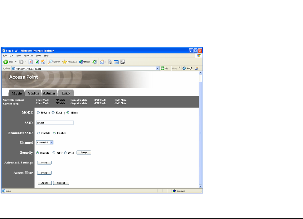
AP Mode configuration
This Access Point supports AP modes. “AP Mode” provides pure access point function. The simplest way to
build up a wireless LAN is to use “AP Mode”.
Parameter Description
Mode 802.11b mode: It allows to select the transmit rate up to 11Mbps 802.11g
mode: It allows to select the transmit rate up to 54Mbps
Mixed mode: It provides best performance for 11g transmission when
you enable the AP mode selection to “Mixed mode”.
SSID The SSID (up to 32 printable ASCII characters) is the unique name
identified in a WLAN. The ID prevents the unintentional merging of two
co-located WLANs. Please make sure that the SSID of all stations in the
same WLAN network are the same. The default SSID is “default”.
Broadcast SSID It will respond to Broadcast SSID requests. If you enable this function,
every wireless station located within the coverage of this access point can
discover this access point easily. If you are building a public wireless
network, enabling this feature is recommended. Disabling "Response to
Broadcast ESSID requests" can provide better security.
Channel Select the appropriate channel from the list provided to correspond with
your network settings. Channels differ from country to country.
Channel 1-11 (North America)
Channel 1-14 (Japan)
Channel 1-13 (Europe)
There are 14 channels available.
Security Disable: Disable the security function.
WEP: WEP is an authentication algorithm, which protects authorized
Wireless LAN users against eavesdropping. The Authentication type and
WEP key of wireless stations must be the same with the Access Point.
This Access Point supports 64/128-bit WEP Encryption function. With this
function, your data will be transmitted over the wireless network securely.
# You can refer to the detail setting from chapter 3.2.6.
WPA: You can use a pre-shared key to authenticate wireless stations and
encrypt data during communication. When you enabled WPA mode, you
32
can not use WEP encryption.
# You can refer to the detail setting from chapter 3.2.7.
Advance setting It provides more powerful features for you to configuring.
# You can refer to the detail setting from chapter 3.2.8.
Access Filter This Access Point allows you to provide a Filter List of MAC addresses
that are allowed associating with this AP.
# You can refer to the detail setting from chapter 3.2.9.
Click Apply button at the bottom of the screen to save the above configurations. You can now
configure other advance sections or start using the Access Point.
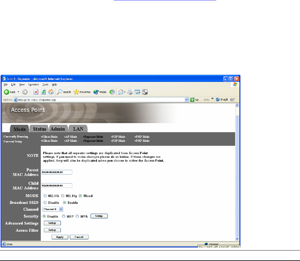
Repeater Mode Configuration
If you want a repeater to bridge with another repeater and provide connection service for othrt
wireless station at the same time, you have to set the access point to “Repeater mode”.
Parameter Description
Parent MAC Address You have to enter the MAC addresses of other access points that join the
bridging work.
Child MAC Address You have to enter the MAC addresses of other access points that join the
bridging work.
Mode 802.11b mode: It allows to select the transmit rate up to 11Mbps 802.11g
mode: It allows to select the transmit rate up to 54Mbps
Mixed mode: It provides best performance for 11g transmission when
you enable the AP mode selection to “Mixed mode”.
Broadcast SSID It will respond to Broadcast SSID requests. If you enable this function,
every wireless station located within the coverage of this access point can
discover this access point easily. If you are building a public wireless
33
network, enabling this feature is recommended. Disabling "Response to
Broadcast ESSID requests" can provide better security.
Channel Select the appropriate channel from the list provided to correspond with
your network settings. Channels differ from country to country.
Channel 1-11 (North America)
Channel 1-14 (Japan)
Channel 1-13 (Europe)
There are 14 channels available.
Security Disable: Disable the security function.
WEP: WEP is an authentication algorithm, which protects authorized
Wireless LAN users against eavesdropping. The Authentication type and
WEP key of wireless stations must be the same with the Access Point.
This Access Point supports 64/128-bit WEP Encryption function. With this
function, your data will be transmitted over the wireless network securely.
# You can refer to the detail setting from chapter 3.2.6.
WPA: You can use a pre-shared key to authenticate wireless stations and
encrypt data during communication. When you enabled WPA mode, you
can not use WEP encryption.
# You can refer to the detail setting from chapter 3.2.7.
Advance setting It provides more powerful features for you to configuring.
# You can refer to the detail setting from chapter 3.2.8.
Access Filter This Access Point allows you to provide a Filter List of MAC addresses
that are allowed associating with this AP.
# You can refer to the detail setting from chapter 3.2.9.
Click Apply button at the bottom of the screen to save the above configurations. You can now
configure other advance sections or start using the Access Point.
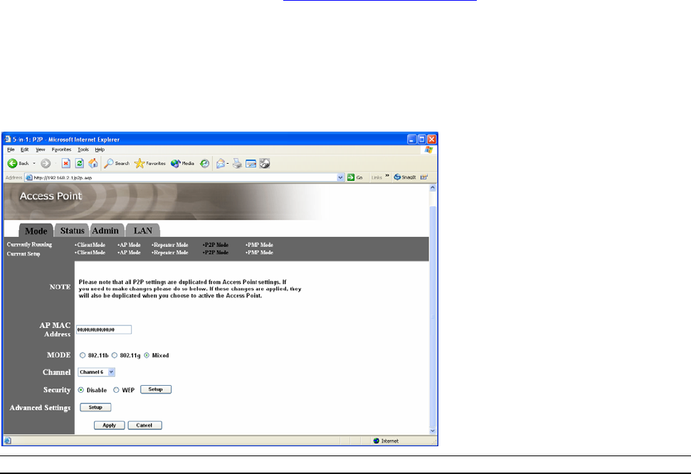
P2P Mode configuration
This function provides to bridge more than 2 wired Ethernet networks together by wireless LAN. You
can use two access points with “P2P mode” to bridge two wired Ethernet networks together.
Parameter Description
AP MAC Address You have to enter the MAC addresses of other access points that join the
bridging work.

34
Mode 802.11b mode: It allows to select the transmit rate up to 11Mbps 802.11g
mode: It allows to select the transmit rate up to 54Mbps
Mixed mode: It provides best performance for 11g transmission when
you enable the AP mode selection to “Mixed mode”.
Channel Select the appropriate channel from the list provided to correspond with
your network settings. Channels differ from country to country.
Channel 1-11 (North America)
Channel 1-14 (Japan)
Channel 1-13 (Europe)
There are 14 channels available.
Security Disable: Disable the security function.
WEP: WEP is an authentication algorithm, which protects authorized
Wireless LAN users against eavesdropping. The Authentication type and
WEP key of wireless stations must be the same with the Access Point.
This Access Point supports 64/128-bit WEP Encryption function. With this
function, your data will be transmitted over the wireless network securely.
# You can refer to the detail setting from chapter 3.2.6.
Advance setting It provides more powerful features for you to configuring.
# You can refer to the detail setting from chapter 3.2.8.
Click Apply button at the bottom of the screen to save the above configurations. You can now
configure other advance sections or start using the Access Point.
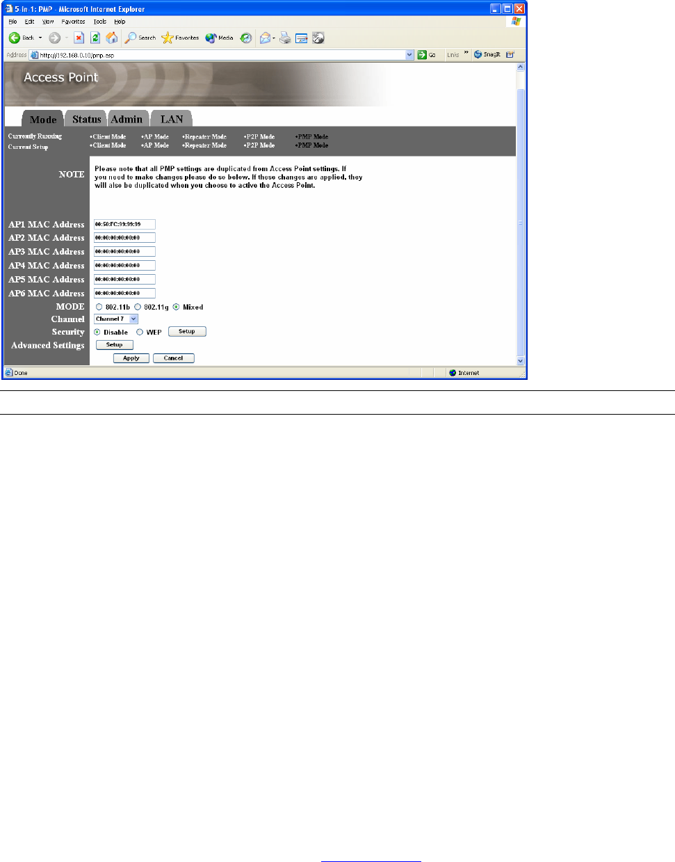
PMP Mode Configuration
This function provides to bridge more than 2 wired Ethernet networks together by wireless LAN. You
can use two access points with “P2P mode” to bridge two wired Ethernet networks together.
35
Parameter Description
AP MAC Address If you want to bridge more than one wired Ethernet networks together with
wireless LAN, you have to enter the MAC addresses of other access
points that join the bridging work.
Mode 802.11b mode: It allows to select the transmit rate up to 11Mbps 802.11g
mode: It allows to select the transmit rate up to 54Mbps
Mixed mode: It provides best performance for 11g transmission when
you enable the AP mode selection to “Mixed mode”.
Channel Select the appropriate channel from the list provided to correspond with
your network settings. Channels differ from country to country.
Channel 1-11 (North America)
Channel 1-14 (Japan)
Channel 1-13 (Europe)
There are 14 channels available.
Security Disable: Disable the security function.
WEP: WEP is an authentication algorithm, which protects authorized
Wireless LAN users against eavesdropping. The Authentication type and
WEP key of wireless stations must be the same with the Access Point.
This Access Point supports 64/128-bit WEP Encryption function. With this
function, your data will be transmitted over the wireless network securely.
# You can refer to the detail setting from chapter 3.2.6.
Advance setting It provides more powerful features for you to configuring.
# You can refer to the detail setting from chapter 3.2.8.
Click Apply button at the bottom of the screen to save the above configurations. You can now
configure other advance sections or start using the Access Point.
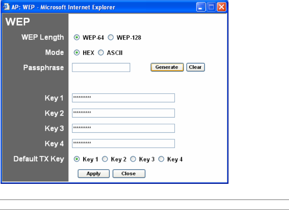
WEP Setting
36
Parameter Description
WEP Length WEP-64: input 10-digit Hex values (in the “A-F”, “a-f” and “0-9” range) or
5-digit ASCII character as the encryption keys.
WEP-128: input 26-digit Hex values (in the “A-F”, “a-f” and “0-9” range) or
13-digit ASCII characters as the encryption keys.
Mode HEX: input Hex values (in the “A-F”, “a-f” and “0-9” range)
ASCII: input alphanumeric format.
Passphrase Enter passphrase and click “Generate”, then the access point will
automatically generate WEP keys by the passphrase for you.
Key 1 - Key 4 To entry 10 Hex digits for 64 bit key, 26 Hex digits for 128 bit key.
Default TX Key Select the WEP key used to encrypt data transmitted in the wireless
network.
Click Apply button at the bottom of the screen to save the above configurations. You can now
configure other advance sections or start using the Access Point.
37
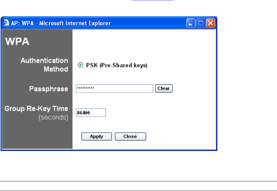
WPA Setting
Parameter Description
Authentication Type The Pre-shared key is used to authenticate and encrypt data transmitted
in the wireless network.
Passphrase To entry at least 8 characters pass phrase as the pre-shared keys.
Group Re-Key Time
(second)
It will auto re-gererate the Key after the defult time (86400) has passed, or
you can change the default time by yourself.
Click Apply button at the bottom of the screen to save the above configurations. You can now
configure other advance sections or start using the Access Point.
38
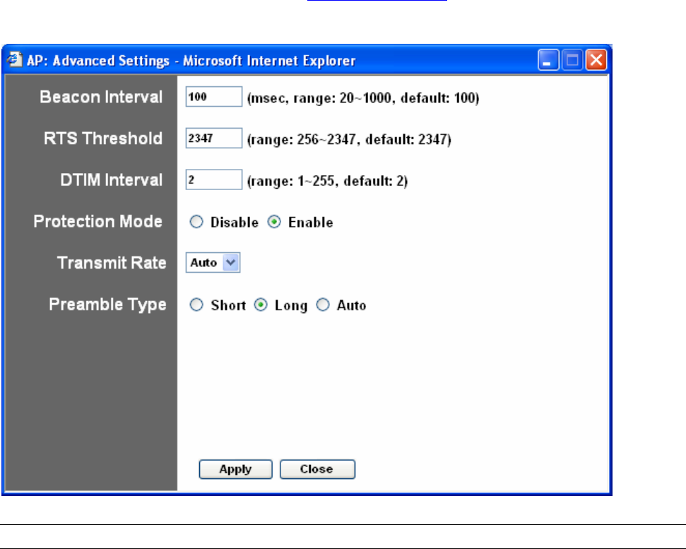
Advanced Setting
Parameter Description
Beacon Interval (20-1000) The period of time that this access point broadcast a beacon. Beacon is
used to synchronize the wireless network.
RTS Threshold (256-2432) When the packet size is smaller the RTS threshold, the access point will
not use the RTS/CTS mechanism to send this packet.
DTIM Period (1-255) This is the interval of the Delivery Traffic Indication Message (DTIM). A
DTIM field is a countdown field informing stations of the next window for
listening to broadcast and multicast messages. When the Access Point
has buffered broadcast or multicast messages for associated stations, it
sends the next DTIM with a DTIM Interval value. Stations for the Access
Point hear the beacons and awaken to receive the broadcast and
multicast messages.
Protection Mode It provides best performance for 11g transmission when you enable it.
Transmit Rate When you enable the station mode selection to “802.11b” and it allows
you to select the speed of 1-11Mbps. When you enable the station mode
selection to “802.11g” and it allows you to select the speed of 1-54Mbps.
Preamble Type Preamble type defines the length of preamble block in the frames during
the wireless communication.
Auto select: It will auto switch to the more suitable method.
Short: It is suitable for high traffic wireless network
Long: It can provide more reliable communication
Click Apply button at the bottom of the screen to save the above configurations. You can now
configure other advance sections or start using the Access Point.
39
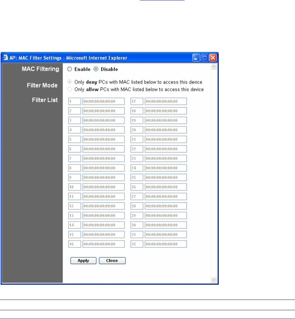
Access Filter
This Access Point allows you to provide a Filter List of MAC addresses that are allowed/denied
associating with this AP.
Parameter Description
MAC Filtering You can enable or disable the MAC Filtering function.
Filter Mode If you select “Only deny PCs with MAC listed below to access this device”,
then all the PCs in the list will be denied to access and all other PCs will
be allowed to access. If you select “Only allow PCs with MAC listed below
to access this device”, then all PCs in the list will be allowed to access but
all other PCs will be denied to access.
Filter List Enter the MAC address of PC that will be managed by the MAC Filtering
rule.
Click Apply button at the bottom of the screen to save the above configurations. You can now
configure other advance sections or start using the Access Point.
40
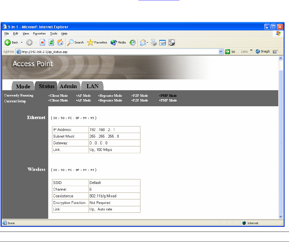
Status Setup
Parameter Description
Ethernet It shows the default IP address, Subnet Mask, Gateway and Link status
information.
Wireless It shows the current Wireless information.
41
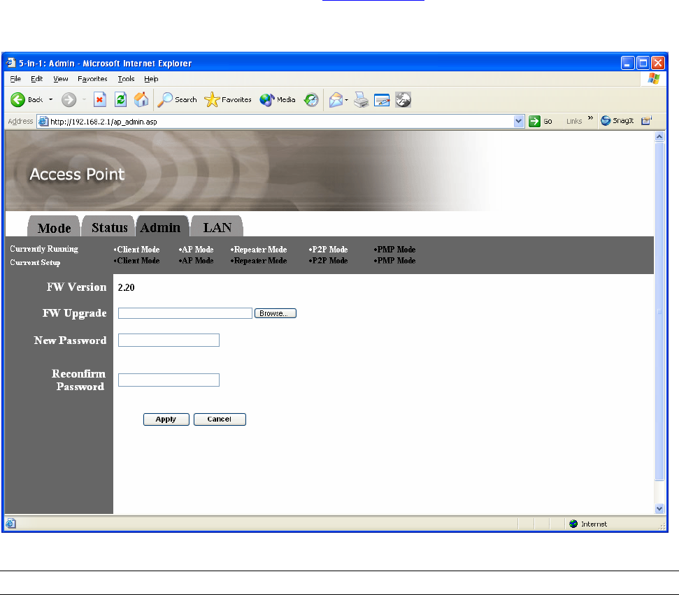
Admin Setup
Parameter Description
FW Version It shows current FW version.
FW Upgrade This tool allows you to upgrade the Access Point’s system firmware. To
upgrade the firmware of your Access Point, you need to download the
firmware file to your local hard disk, and enter that file name and path in
the appropriate field on this page. You can also use the Browse button to
find the firmware file on your PC. Please reset the Access Point when the
upgrade process is complete.
New Password Enter the password (up to 32-digit alphanumeric string) you want to login
to the Access Point. Note that the password is case-sensitive.
Reconfirm Password Reconfirm the password (up to 32-digit alphanumeric string) you want to
login to the Access Point. Note that the password is case-sensitive.
Click Apply button at the bottom of the screen to save the above configurations. You can now
configure other advance sections or start using the Access Point.
42
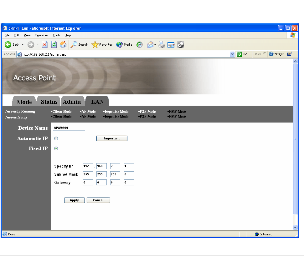
LAN Setup
Parameter Description
Device Name It shows current FW version.
Automatic IP Selecting this option is not advised unless you have direct access to the
device that provides the IP address.
Fixed IP Specify IP: Designate the Access Point’s IP Address. This IP Address
should be unique in your network. The default IP Address is 192.168.2.1.
Subnet Mask: Specify a Subnet Mask for your LAN segment. Gateway:
Specify the default gateway IP of this Access Point.
Click Apply button at the bottom of the screen to save the above configurations. You can now
configure other advance sections or start using the Access Point.