Kirisun Communication PT820002 Mobile Radio User Manual PT8200 User s Manual
Kirisun Communications Co., Ltd Mobile Radio PT8200 User s Manual
UserManual.wiki
>
Kirisun Communication
>
PT820002 User Manual
Users Manual
Navigation menu
Upload a User Manual
Namespaces
Wiki Guide
HTML
PDF
Info
Views
User Manual
Discussion / Help
Navigation
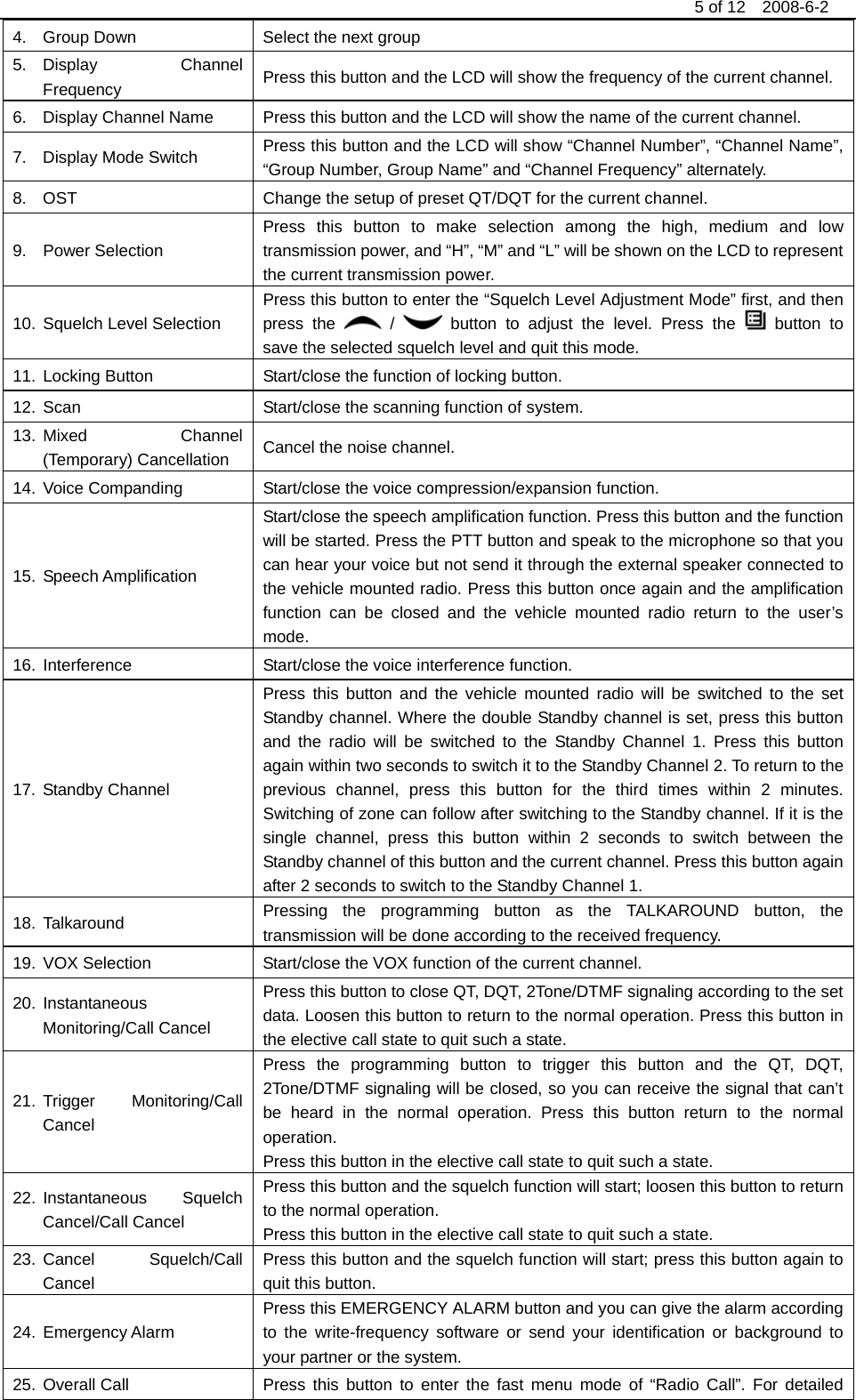
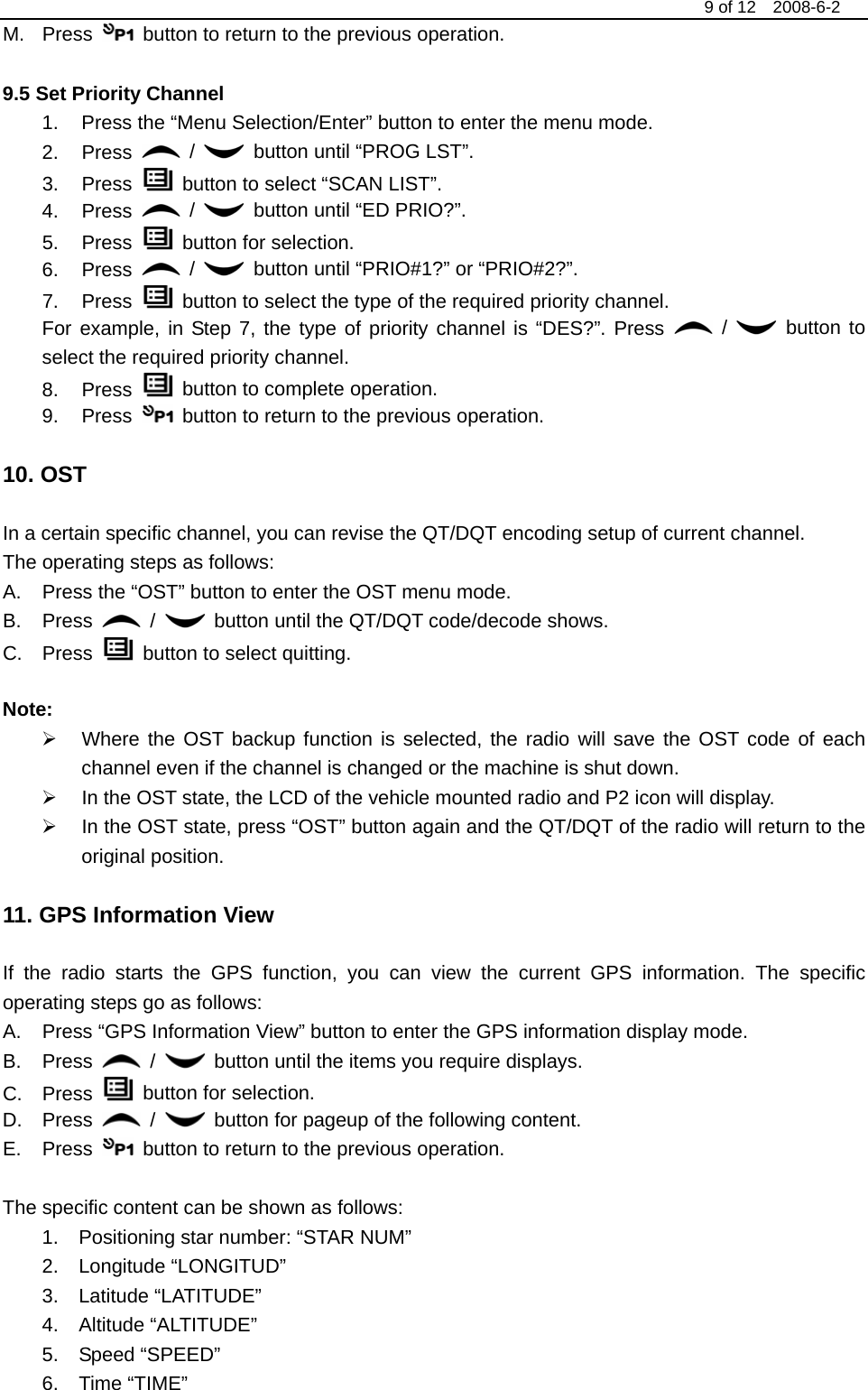
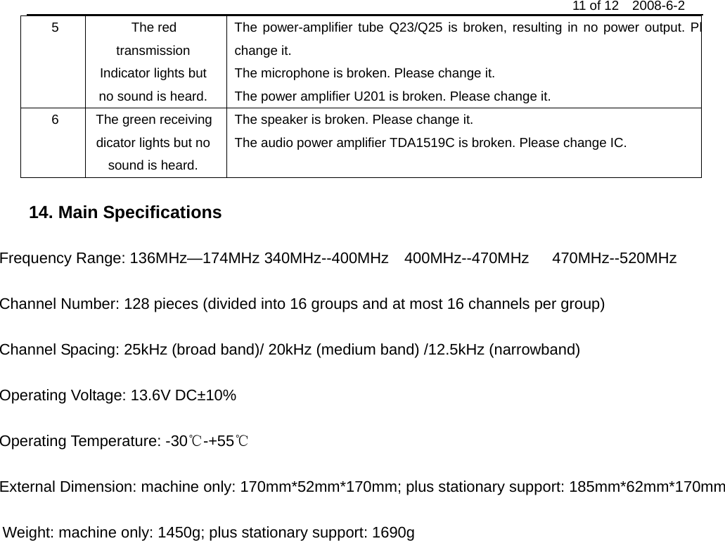
![10 of 12 2008-6-2 12. Wired Replication Mode If the wired replication function is set, the intercom will not quit after entering the wired replication mode. If it returns to the user mode, the user needs to restart the machine. The operating steps go as follows: 1 Press [P1] and [P2] buttons for power-on to show “CLONE” (for two seconds) and enter the replication mode. If such a mode is not allowed, it will enter the user mode. 2 Connect the pickaback plane with the wired replication cable first, and then turn on the power button for the pickaback plane. 3 Press the host [P4] button for replication. At this time the red host indicator will light and the data will be transmitted to the pickaback plane from the host. In the period when the pickaback plane receives the data, it will show “PROGRAM” and the green indicator light. The host will show “SUCCESS” and the pickaback plane will automatically restart upon receipt of all data. 4 Press the [P4] button and the host will return to the replication mode. Continuous replication will start from Step 3. Note: The wired replication mode can be started or prohibited through the PC program software. Once such a mode is prohibited, the intercom can’t enter the wired replication mode. 13. Common Failures and Troubleshooting No. Failures Causes and Troubleshooting 1 No reaction after startup A The power cable is not joined with the battery or the host reliably. Plconnect the power cable reliably. B The protective tube of power cable is burnt out. Please Change it. C The power button is of poor contact. Please change the silica gel button or button. D The battery is out of power. Please charge or change it. E CPU is broken, Please change IC. 2 Phase lock loop unlocked (Beeping) The crystal X1 of phase lock loop is broken. Please change it. The oscillator tube is broken. Please change it. The chip U101 of phase lock loop is broken. Please change IC. 3 No talkback The frequency for talkback is not right. Please re-select the channel of the sfrequency. The QT/DQT signaling code for talkback is not the same. Please reset it. Plcheck the setup of receive/send signaling system for both parties. It is out of the effective communication range. 4 No receiving signal The antenna is not in good contact. Please fasten the antenna head. The high-frequency amplifying tube Q26 is broken. Please change it. The squelch level is set high so the squelch can’t be started. Please reset the squlevel. The mixed tube Q21 is broken. Please change it. The FM chip U101 is broken. Please change IC.](https://usermanual.wiki/Kirisun-Communication/PT820002/User-Guide-1004387-Page-11.png)