Kirisun Communication PT820002 Mobile Radio User Manual PT8200 User s Manual
Kirisun Communications Co., Ltd Mobile Radio PT8200 User s Manual
Users Manual

MANDATORY SAFETY INSTRUCTIONSTO INSTALLERS AND USERS
z Use Only manufacturer or dealer supplied antennas.
z Antenna minimum safe distance: 108 cm.
z Antennas used for this transmitter must not exceed an antenna gain of 3 dBi.
The FCC (Federal Communications Commission) has adopted a safety standard for human
exposure to RF energy which is below the OSHA (Occupational Safety and Health Act)
limits.
z Antenna mounting: The antenna supplied by the manufacturer or radio dealer must not be
mounted at a location such that during radio transmission, any person can come closer than
the above indicated minimum safe distance to the antenna (i.e. 108cm).
z To comply with current FCC RF Exposure limitations, the antenna must be installed at or
exceeding the minimum safe distance indicated above, and in accordance with the
requirements to the antenna manufacturer or supplier.
z Vehicle installation: The antenna can be mounted at the center of a vehicle metal roof or
trunk lid if the minimum safe distance is observed.
Antenna substitution: Don’t substitute any antenna for the one supplied or recommended by
the manufacturer or radio dealer. You may be exposing person(s) to excessive radio frequency
radiation. You may contact your radio dealer or the manufacturer for further instructions.
Warning
Maintain a separation distance from the antenna to person(s) at least 108cm.
“This transmitter is authorized to operate with a maximum duty factor of 50%, in a typical
push-to-talk mode, for satisfying FCC RF exposure compliance requirements.”
Caution:
Changes or modifications not expressly approved by the party responsible for compliance could void
the user's authority to operate the equipment.

1 of 12 2008-6-2
Operating Instruction of PT8200
Contents
1 Package-opened Inspection and Device................................................................................1
2 Familiarity with the Machine...................................................................................................2
3 Basic Operation .....................................................................................................................4
4 Program Button Function .......................................................................................................4
5Intercom Call .........................................................................................................................6
5.1 Selective Call..............................................................................................................6
5.2 Send Selective Call ....................................................................................................6
5.3Receive Selective Call ...............................................................................................6
5.4Call Prompt................................................................................................................6
6 Select Group..........................................................................................................................7
7 Talkaround .............................................................................................................................7
8 Applied Items .........................................................................................................................7
9 Scan ...................................................................................................................................8
9.1 Start/Close Scan Function .............................................................................................8
9.2 Cancel Noise Channel...................................................................................................8
9.3 Edit Scan List.................................................................................................................8
9.4 Increase or Cancel the Channels in the Scan List .........................................................8
9.5 Set Priority Channel.......................................................................................................9
10 OST OST .............................................................................................................................9
11 GPS Information View ..........................................................................................................9
12 Wired Replication Mode.....................................................................................................10
13 Common Failures and Troubleshooting .............................................................................10
14 Main Specifications ............................................................................................................ 11
1 Package-opened Inspection and Device
Please check the host in the package and the supplied accessories in the following table prior to
use of this Machine. Where any articles are found lost or damaged, please contact the local
distributor without delay.
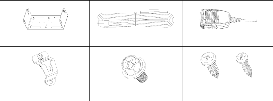
1.1 Supplied Accessories
No. Accessories Quantity
01 Stationary Support 1
02 Power Cable 1
03 Hand Microphone 1
04 Microphone Hanger 1
05 M4*10 Combination Screw 4
06 M4*16 Self-tapping Screw 2
07 M5*16 Self-tapping Screw 4
08 Operating Instruction 1
09 Warranty Card 1
2 of 12 2008-6-2
Stationary Support Power Cable
Hand Microphone
Microphone Hanger
M4*10 Combination Screw
M5*16 / M4*16 Self-tapping
Screw
1.2 Preparatory Work
1.21 Connection of Power Cable
First of all, please check whether there is a hole for the power cable on the insulating board. If no,
please bore the board with the suitable drill bit and fix a rubber grommet on it.
Afterwards, please have the cable pass through the insulating board and lead from the car into the
car engine. Connect the red conductor to the positive terminal of the accumulator and the black
conductor to the negative terminal.
At last ring the remained conductor and fix it.
Note: Please maintain the sufficient relaxation of the power cable to make it convenient to dismantle
the radio in the state of power connection.
1.22 Fixation of Radio
Warning: For the purpose of passengers’ safety, please fix the radio firmly on the stationary support
so that the radio will not be loosened in case of collision.
1) The stationary support is taken as an example. Draw the position and drill a hole on the
instrument panel first, and then fix the stationary support with 4 M5*16 self-tapping screws.
(Note: please fix the radio at the position convenient for operation and control, and leave an
enough space for fixation and connection of the cable.)
2) Slide the radio into the stationary support and fix it with 4 M4*10 combination screws (plus plain
washer and spring washer). (Different combinations of fixing holes are selectable to adjust the
radio to the proper height and visual angle.)
3) Connect the antenna and the power cable to the radio.
4) Fix the microphone hanger at the position easy to use, with 2 M4*16 self-tapping screws. (The
microphone and its cable should be fixed at the position not affecting safe driving.)
5) Connect the microphone to the microphone jack on the front panel of the radio and put it on the
hanger.
Note: Where replacement of the protective tube for the power cable is required, please use the one
of the same specification without fail. It is not allowed to change it into the tube of higher capacity.
2.Familiarity with the Machine
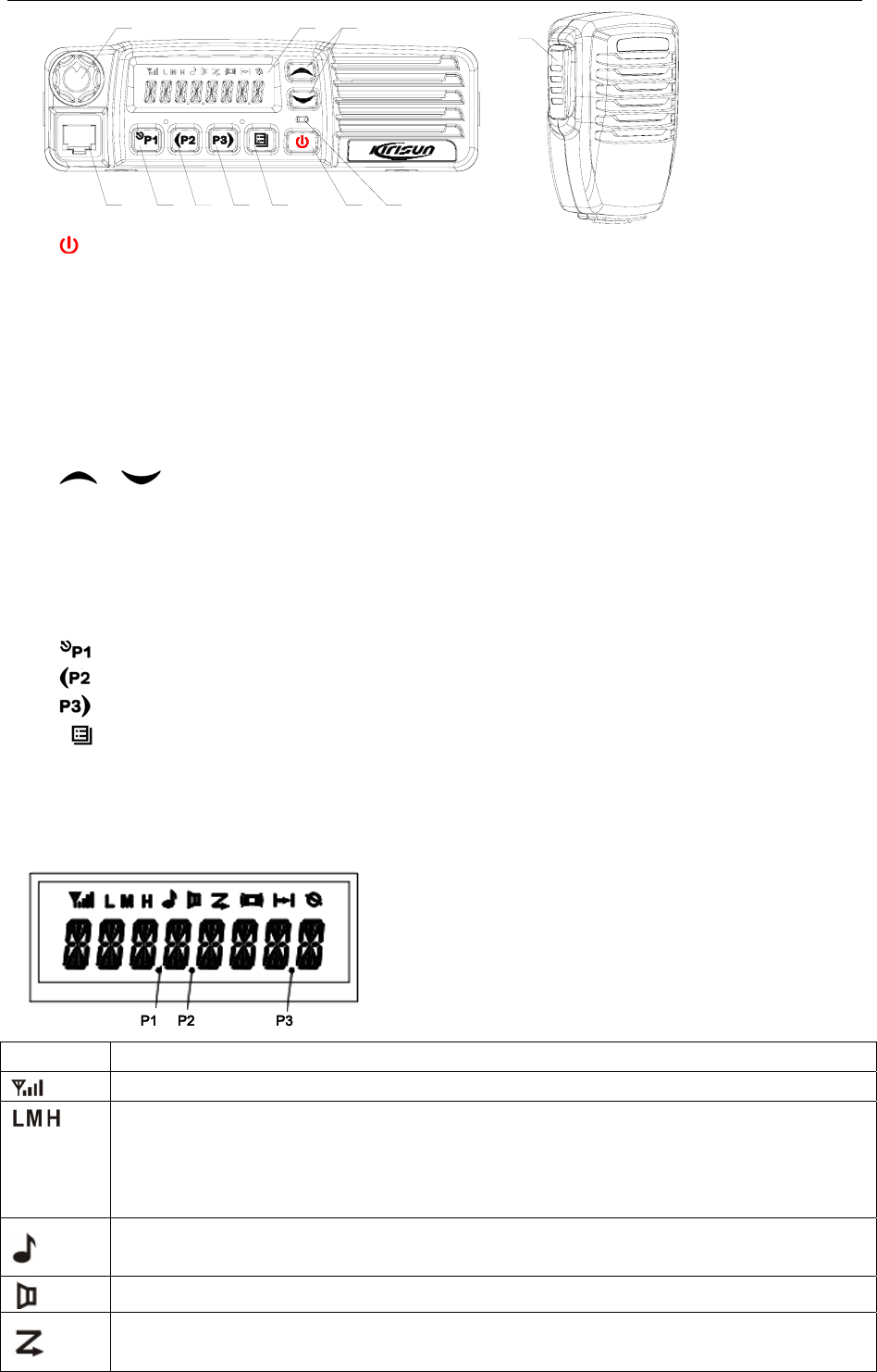
2.1 Description of External View
3 of 12 2008-6-2
⑴⑵
⑶⑷⑸
⑺⑻⑼⑽⑹
⑾
(1) power button
Press this button for a long time to start or close the intercom.
(2)LED indicator
The red indicator will light when it transmit the carrier; the green indicator will light when it
receives the carrier.
The indicator will flicker and give the orange light when it receives Dtmf or 2Tone signal
consistent with the set one locally.
The red indicator flickers in the scanning process.
(3) / button (programming button)
(4)LCD display screen
For details, see “LCD Display”.
(5)Volume Control knob
To be used to adjust volume.
(6)Microphone/Programming Interface
(7) button (programming button)
(8) button (programming button)
(9) button (programming button)
(10) button (programming button)
(11)PPT button (on the hand microphone)
Press the PTT button first, and then speak to the microphone to transmit the sound to the
other. Please don’t press this button if you want to listen to the other.
2.2 Display Screen
Display Description
It means the receiving signal strength. 4 lines mean the strongest signal.
Transmission power level
”L” means the transmission of signal for the intercom at the lower power;
”M” means the transmission of signal for the intercom at the medium power;
”H” means the transmission of signal for the intercom at the high power;
Receive Call display
The intercom receives a selective call/call reminder.
Monitoring State display
Scanning State display
4 of 12 2008-6-2
Companding State display
Talkaround State display
Interference State display
P2 OST State display
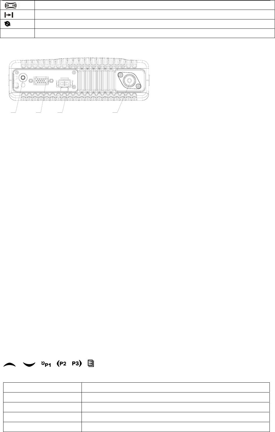
2.3 Rear Panel
⑴⑵⑶⑷
(1)Antenna Interface
(2)Power Interface
(3)15Pin Extended Serial Interface
(4)External Speaker Interface
3. Basic Operation
1. Startup:
Press the red POWER button for a long time (at least 1.5 seconds) to start/close the intercom.
2. Volume
Press the “MONITOR” or “Squelch” button to listen to the background noise first, and then
adjust the volume by turning the volume control knob.
3. Channel
The intercom can provide 128 conventional channels (There are totally 16 groups and each has
at most 16 channels). Press the “CHANNEL UP” or “CHANNEL DOWN” button to select the
channel. Press the “GROUP UP” or “GROUP DOWN” button to select the group you require.
4. Transmission
To send a call, press the PTT button and speak to the microphone in the normal voice. Please
keep the microphone about 3 or 4 cm far from your mouth. After speaking, please loosen the
PTT button.
5. Receive
The intercom will return to the receiving state after you loosen the PTT button.
The distributor may have set the QT/DQT signaling in the program of your intercom. Where the
channels for these functions are set, you can only hear the call from other radios in your system,
but not all calls.
4. Program Button Function
/ ,,,, can be programmed as one of the auxiliary functions.
Buttons Function Description
0. None No function setup
1. Channel Up Select the previous channel
2. Channel Down Select the next channel
3. Group Up Select the previous group

5 of 12 2008-6-2
4. Group Down Select the next group
5. Display Channel
Frequency Press this button and the LCD will show the frequency of the current channel.
6. Display Channel Name Press this button and the LCD will show the name of the current channel.
7. Display Mode Switch Press this button and the LCD will show “Channel Number”, “Channel Name”,
“Group Number, Group Name” and “Channel Frequency” alternately.
8. OST Change the setup of preset QT/DQT for the current channel.
9. Power Selection
Press this button to make selection among the high, medium and low
transmission power, and “H”, “M” and “L” will be shown on the LCD to represent
the current transmission power.
10. Squelch Level Selection
Press this button to enter the “Squelch Level Adjustment Mode” first, and then
press the / button to adjust the level. Press the button to
save the selected squelch level and quit this mode.
11. Locking Button Start/close the function of locking button.
12. Scan Start/close the scanning function of system.
13. Mixed Channel
(Temporary) Cancellation Cancel the noise channel.
14. Voice Companding Start/close the voice compression/expansion function.
15. Speech Amplification
Start/close the speech amplification function. Press this button and the function
will be started. Press the PTT button and speak to the microphone so that you
can hear your voice but not send it through the external speaker connected to
the vehicle mounted radio. Press this button once again and the amplification
function can be closed and the vehicle mounted radio return to the user’s
mode.
16. Interference Start/close the voice interference function.
17. Standby Channel
Press this button and the vehicle mounted radio will be switched to the set
Standby channel. Where the double Standby channel is set, press this button
and the radio will be switched to the Standby Channel 1. Press this button
again within two seconds to switch it to the Standby Channel 2. To return to the
previous channel, press this button for the third times within 2 minutes.
Switching of zone can follow after switching to the Standby channel. If it is the
single channel, press this button within 2 seconds to switch between the
Standby channel of this button and the current channel. Press this button again
after 2 seconds to switch to the Standby Channel 1.
18. Talkaround Pressing the programming button as the TALKAROUND button, the
transmission will be done according to the received frequency.
19. VOX Selection Start/close the VOX function of the current channel.
20. Instantaneous
Monitoring/Call Cancel
Press this button to close QT, DQT, 2Tone/DTMF signaling according to the set
data. Loosen this button to return to the normal operation. Press this button in
the elective call state to quit such a state.
21. Trigger Monitoring/Call
Cancel
Press the programming button to trigger this button and the QT, DQT,
2Tone/DTMF signaling will be closed, so you can receive the signal that can’t
be heard in the normal operation. Press this button return to the normal
operation.
Press this button in the elective call state to quit such a state.
22. Instantaneous Squelch
Cancel/Call Cancel
Press this button and the squelch function will start; loosen this button to return
to the normal operation.
Press this button in the elective call state to quit such a state.
23. Cancel Squelch/Call
Cancel
Press this button and the squelch function will start; press this button again to
quit this button.
24. Emergency Alarm
Press this EMERGENCY ALARM button and you can give the alarm according
to the write-frequency software or send your identification or background to
your partner or the system.
25. Overall Call Press this button to enter the fast menu mode of “Radio Call”. For detailed
6 of 12 2008-6-2
operation, see “Menu Operation”.
26. Call Button 1 As set, transmit the preset code.
27. Call Button 2 As set, transmit the preset code.
28. Call Button 3 As set, transmit the preset code.
29. Call Button 4 As set, transmit the preset code.
30. Menu Selection/Enter Press this button to activate the menu mode. Entering the menu mode, press
this button to select and save the items in the menu.
31. Speaker Alarm
Start/close the speaker function. After you press this button, the speaker
function will be started. If the radio receives the matched dual-tone/two-tone
multi-frequency code, it will give a warning sound. Press this button again and
this function will be closed.
32. Lease Time View Press this button and the LCD will show the remained time of current lease.
33. Independent Operation Start/close the independent operation function.
34. Scan List Edit Press this button and the radio will enter the fast menu mode for scan list edit.
For details, see “Menu Operation”.
35. GPS Information View Press this button and the radio will enter the menu mode of GPS Information
Menu.
36. VOX Level Selection
Press this button to enter the VOX Level Adjustment Mode”. Press /
button to adjust VOX level. Press button to save the selected VOX
level and quit this mode.
Monitoring/Hook Detection: select the hook function or start the monitoring function of desk
microphone.
5. Intercom Call
5.1 Selective Call
5.2 Send Selective Call
A. Press “Menu Selection/Enter” button to enter the menu mode.
B. Press / button until “RADIOCAL”.
C. Press button to select “SEL CALL”.
D. Press / button until the required call list appears.
E. Press “PTT” button to send the selective call.
F. Press “PTT” button and speak to the microphone in normal voice. Please keep the microphone
about 3 to 4 cm far from your mouth. After speaking, please loosen the “PTT”.
G. Press button to return to the previous operation.
5.3Receive Selective Call
Receiving a selective call, you will hear the prompt tone and find the orange indicator flickers.
icon flickers and the calling party’s ID code or name displays.
Press PPT button for callback.
5.4Call Prompt
After the radio receives the call prompt, the prompt tone will sound and the orange indicator flicker.
icon flickers and the calling party’s ID code or name shows until someone answers. Press the
“PTT” button for callback or other buttons for cancellation.
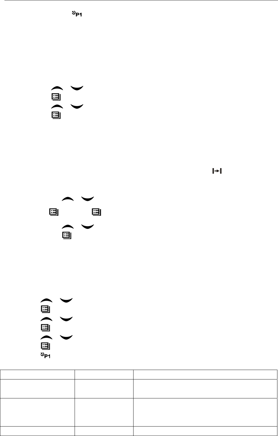
A. Press “Menu Selection/Enter” button to enter the menu mode.
B. Press / button until “RADIOCAL”.
C. Press button to select “CALL ALT”.
D. Press / button until the required call list shows.
7 of 12 2008-6-2
E. Press “PTT” button to utter the selective call.
F. After calling, press button to return the previous operation.
6. Select Group
According to the setup of the communication network, the vehicle mounted radio can be distributed
to different groups. Select the proper group to realize calling with the vehicle mounted radio of
different groups.
1. Select the group through menu.
A. Press the “Menu Selection/Enter” button to enter the menu mode.
B. Press / button until “ZONE”.
C. Press button for selection.
D. Press / button until the group name you require appears.
E. Press button for selection.
2. Select the group through “GROUP UP” or “GROUP DOWN”.
7. Talkaround
In the communication network, you can expand communication range through the repeater, but
when the vehicle mounted radio is out of the communication range, you can connect with other
radio in the talkaround method. The talkaround function can show through .
1. Select the group through menu.
A. Press the “Menu Selection/Enter” button to enter the menu mode.
B. Press / button until “RPTRTALK”.
C. 按选择 Press button for selection.
D. Press / button until “REPEATE” or “TALKRND”.
E. Press button for confirmation.
2. Switch the talkaround or repeater mode through “talkaround”.
8. Applied Items
The applied item can help you customize some setups of the radio.
Operating steps as follows:
A. Press the “Menu Selection/Enter” button to enter the menu mode.
B. Press / button until “UTILITY”.
C. Press button for selection.
D. Press / button until the items you require show.
E. Press button for confirmation. The radio will show the current setup.
F. Press / button to show all items that can be set with this item.
G. Press button to select this setup.
H. Press button to return to the previous operation.
Change the setup items in the following table as per the previous steps.
Items Selectable Setups Functions
Squelch Level
"SQL LEV "
SQL 0 ~ 9 Change the squelch level of the radio.
Transmission Power
"PWR LEV "
"PWR LOW "
"PWR MID ",
"PWR HI "
Select among high, medium and low transmission
power.
VOX Level VOX 0 ~ 9 Change the VOX level of the radio.

8 of 12 2008-6-2
"VOX LEV "
Backlight
"BACK LED"
“BLED OFF"
"BLED ON "
"BL AUTO "
Select among such modes of backlight as
“turnoff”, “normal turn-on” or “auto”.
MCU software version
display
"SOFT VER"
……
Eg.“R01.00”
Show the software version.
9. Scan
In order to receive the calls from many channels, the intercom can be programmed to scan these
channels. At most there are 16 channels in each scan list. Each channel can use a scan list
together with others or alone.
9.1 Start/Close Scan Function
You can press “SCAN” button directly from the menu to activate the scan function. When
the scan function is started, icon and your channel will display at the same time.
In the scan state, the red indicator will flicker. When the scan is stopped, the indicator will
stop flickering.
During the period from the scan state the menu mode, the radio will stop scanning. After
the menu is quitted, the scanning will go on.
2. Enter the scan state through menu mode.
A. Press the “Menu Selection/Enter” button to enter the menu mode.
B. Press / button until “SYS SCAN”.
C. Press button for selection.
D. Press / button until “SCAN ON?” or “SCAN OF?”.
E. Press button for confirmation.
3. Use the scan button.
A. Press “SCAN” button to activate the scan function.
B. Press “SCAN” button again to close the scan function.
9.2Cancel Noise Channel
If a channel continuously produces noise or interference, press the “Mixed Channel (Temporary)
Cancellation” button to cancel this channel from the scan list temporarily.
Note: the priority channel can’t be canceled and the last one in the scan list, either.
Quit the scan mode first, and then re-enter such a mode. If the “Mixed Channel Reset” can work,
the cancelled channel can be added into the scan list.
9.3 Edit Scan List
9.4 Increase or Cancel the Channels in the Scan List
G. Press the “Menu Selection/Enter” button to enter the menu mode.
H. Press / button until “PROG LST”.
A. Press button to select “SCAN LIST”.
I. Press / button until “ADD LST?” or DEL LST?”.
J. Press button for selection.
K. Press / button until the channel you want to add or cancel displays.
L. Press button to complete operation and the show “CHN SAVE” or “CHN DEL”.

9 of 12 2008-6-2
M. Press button to return to the previous operation.
9.5 Set Priority Channel
1. Press the “Menu Selection/Enter” button to enter the menu mode.
2. Press / button until “PROG LST”.
3. Press button to select “SCAN LIST”.
4. Press / button until “ED PRIO?”.
5. Press button for selection.
6. Press / button until “PRIO#1?” or “PRIO#2?”.
7. Press button to select the type of the required priority channel.
For example, in Step 7, the type of priority channel is “DES?”. Press / button to
select the required priority channel.
8. Press button to complete operation.
9. Press button to return to the previous operation.
10. OST
In a certain specific channel, you can revise the QT/DQT encoding setup of current channel.
The operating steps as follows:
A. Press the “OST” button to enter the OST menu mode.
B. Press / button until the QT/DQT code/decode shows.
C. Press button to select quitting.
Note:
¾ Where the OST backup function is selected, the radio will save the OST code of each
channel even if the channel is changed or the machine is shut down.
¾ In the OST state, the LCD of the vehicle mounted radio and P2 icon will display.
¾ In the OST state, press “OST” button again and the QT/DQT of the radio will return to the
original position.
11. GPS Information View
If the radio starts the GPS function, you can view the current GPS information. The specific
operating steps go as follows:
A. Press “GPS Information View” button to enter the GPS information display mode.
B. Press / button until the items you require displays.
C. Press button for selection.
D. Press / button for pageup of the following content.
E. Press button to return to the previous operation.
The specific content can be shown as follows:
1. Positioning star number: “STAR NUM”
2. Longitude “LONGITUD”
3. Latitude “LATITUDE”
4. Altitude “ALTITUDE”
5. Speed “SPEED”
6. Time “TIME”

10 of 12 2008-6-2
12. Wired Replication Mode
If the wired replication function is set, the intercom will not quit after entering the wired replication
mode. If it returns to the user mode, the user needs to restart the machine.
The operating steps go as follows:
1 Press [P1] and [P2] buttons for power-on to show “CLONE” (for two seconds) and enter the
replication mode. If such a mode is not allowed, it will enter the user mode.
2 Connect the pickaback plane with the wired replication cable first, and then turn on the power
button for the pickaback plane.
3 Press the host [P4] button for replication. At this time the red host indicator will light and the
data will be transmitted to the pickaback plane from the host. In the period when the pickaback
plane receives the data, it will show “PROGRAM” and the green indicator light. The host will
show “SUCCESS” and the pickaback plane will automatically restart upon receipt of all data.
4 Press the [P4] button and the host will return to the replication mode. Continuous replication
will start from Step 3.
Note: The wired replication mode can be started or prohibited through the PC program software.
Once such a mode is prohibited, the intercom can’t enter the wired replication mode.
13. Common Failures and Troubleshooting
No. Failures Causes and Troubleshooting
1 No reaction after
startup
A The power cable is not joined with the battery or the host reliably. P
l
connect the power cable reliably.
B The protective tube of power cable is burnt out. Please Change it.
C The power button is of poor contact. Please change the silica gel button or
button.
D The battery is out of power. Please charge or change it.
E CPU is broken, Please change IC.
2 Phase lock loop
unlocked
(Beeping)
The crystal X1 of phase lock loop is broken. Please change it.
The oscillator tube is broken. Please change it.
The chip U101 of phase lock loop is broken. Please change IC.
3 No talkback The frequency for talkback is not right. Please re-select the channel of the
s
frequency.
The QT/DQT signaling code for talkback is not the same. Please reset it. P
l
check the setup of receive/send signaling system for both parties.
It is out of the effective communication range.
4 No receiving signal The antenna is not in good contact. Please fasten the antenna head.
The high-frequency amplifying tube Q26 is broken. Please change it.
The squelch level is set high so the squelch can’t be started. Please reset the sq
u
level.
The mixed tube Q21 is broken. Please change it.
The FM chip U101 is broken. Please change IC.

11 of 12 2008-6-2
5 The red
transmission
Indicator lights but
no sound is heard.
The power-amplifier tube Q23/Q25 is broken, resulting in no power output. P
l
change it.
The microphone is broken. Please change it.
The power amplifier U201 is broken. Please change it.
6 The green receiving
dicator lights but no
sound is heard.
The speaker is broken. Please change it.
The audio power amplifier TDA1519C is broken. Please change IC.
14. Main Specifications
Frequency Range: 136MHz—174MHz 340MHz--400MHz 400MHz--470MHz 470MHz--520MHz
Channel Number: 128 pieces (divided into 16 groups and at most 16 channels per group)
Channel Spacing: 25kHz (broad band)/ 20kHz (medium band) /12.5kHz (narrowband)
Operating Voltage: 13.6V DC±10%
Operating Temperature: -30℃-+55℃
External Dimension: machine only: 170mm*52mm*170mm; plus stationary support: 185mm*62mm*170mm
Weight: machine only: 1450g; plus stationary support: 1690g

12 of 12 2008-6-2