Kodak 4020 Users Manual Service For The Ektapro Projector
(9020CINE) to the manual c0993dde-fcc3-468d-96dc-60716c207bab
2015-02-04
: Kodak Kodak-4020-Users-Manual-370832 kodak-4020-users-manual-370832 kodak pdf
Open the PDF directly: View PDF ![]() .
.
Page Count: 136 [warning: Documents this large are best viewed by clicking the View PDF Link!]
- Library
- Manual Contents
- Kodak EKTAPRO Slide Projector Service Manual
- TABLE OF CONTENTS
- 1. GENERAL INFORMATION 1-3
- 2. INTRODUCTION 2-1
- 3. THEORY GUIDE 3-1
- 4. DISASSEMBLY/ASSEMBLY 4-1
- UPPER HOUSING 4-1
- BUTTONS and COVER PLATES 4-2
- CENTER HOUSING 4-4
- FAN, KEYBOARD PCB and TRAY MOTION PCB 4-8
- BACK PANEL PCB 4-10
- TRANSFORMER, POWER SUPPLY PCB and BACK PLATE ASSEMBLY 4-11
- MECHANISM FRAME and LENS MOUNT 4-12
- LENS MOUNT 4-13
- RETAINER AF ASSEMBLY 4-16
- MECHANISM FRAME 4-18
- AUTO FOCUS PCB and FOCUS MOTOR 4-21
- Master Board PCB 4-22
- LOWER HOUSING 4-25
- DUAL LAMP MODULE 4-26
- Lubrication 4-30
- 5. DIAGNOSTICS 5-1
- Diagnostic Overview EKTAPRO 4020/5020/7020/9020 and 9020/CINE 5-1
- Preparation 5-3
- No Function 5-4
- Switch on Procedure Problems 5-9
- Lamp Problems EP 4020/5020/7020/9020 and 9020/CINE 5-12
- Mirror Position 5-17
- Switch On Procedure 5-18
- Switch On Procedure complete - No Keyboard Function 5-19
- No function with REMOTE CONTROL 5-20
- Cable Remote 5-23
- No Slide Transport forward/reverse and other projection problems 5-24
- Shutter Problems 5-35
- Fan Problems 5-27
- Slide Obstruction in Slide Tray 5-29
- Wrong Transport Step by 80/140 SLIDE TRAY 5-30
- No Focus Actuation 5-32
- No Standby Function 5-33
- Communication Trouble 4010/5010/9010 5-35
- AUTO FOCUS 5020/9020 and 9020/CINE: No AUTO FOCUS Function 5-39
- Accessory Slot 7020/9020 5-40
- 6. Projector Checking 6-1
- 7. MAINTENANCE 7-1
Publication No. SM 2547-1
03/98
SERVICE MANUAL
for the
KODAK EKTAPRO
Slide Projector
Model 4020, 5020, 7020, 9020, (9020/CINE)
© Kodak AG, Stuttgart 1998
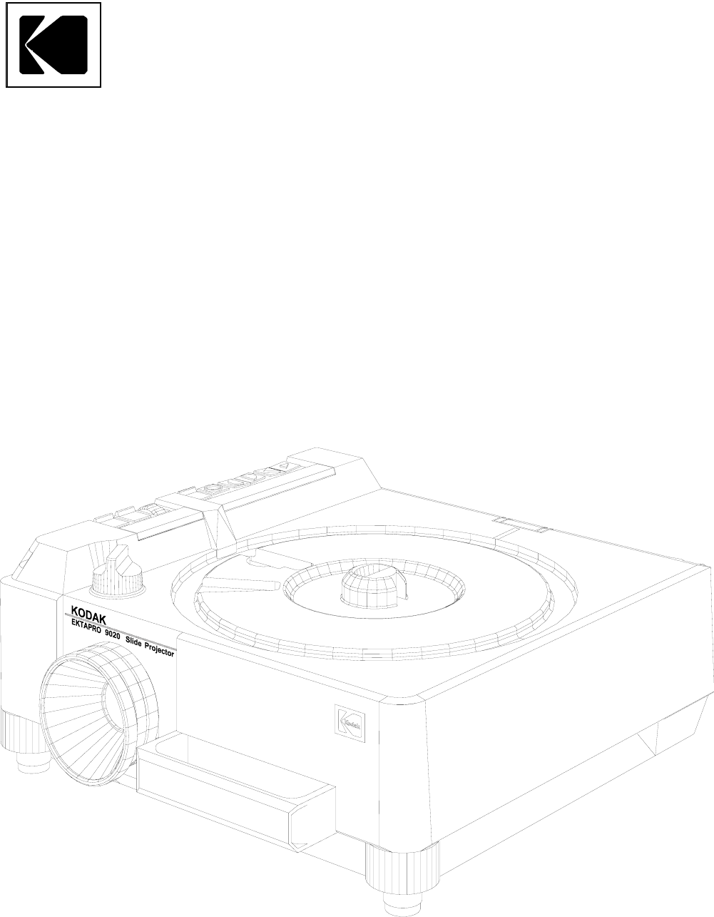
Model 9020
Kodak
Kodak AG, Stuttgart I 03/98

PLEASE NOTE
The information contained herein is based on the experience and knowledge relating to the subject
matter gained by Kodak prior to publication. No patent license is granted by this information. Kodak
reserves the right to change this information without notice, and makes no warranty, express or
implied, with respect to this information. Kodak shall not be liable for any loss or damage, including
consequential or special damages, resulting from the use of this information, even if loss or damage
is caused by Kodak’s negligence or other fault.
Service Manual SM 2547-1
03/98 II Kodak AG, Stuttgart

TABLE OF CONTENTS
ELECTROSTATIC DISCHARGE......................................................................................................... 1-1
Overview..................................................................................................................................... 1-1
Awareness.................................................................................................................................. 1-1
Action ......................................................................................................................................... 1-1
Every Day ................................................................................................................................... 1-2
During Maintenance and Repair................................................................................................. 1-2
1. GENERAL INFORMATION.............................................................................................................. 1-3
Service Tools ...................................................................................................................................... 1-3
For Models 4020/5020/7020/9020 and 9020/CINE ............................................................................ 1-3
Safety Precaution................................................................................................................................ 1-4
Safety Check ...................................................................................................................................... 1-5
2. INTRODUCTION .............................................................................................................................. 2-1
Projector Models ................................................................................................................................. 2-2
EKTAPRO Model 4020............................................................................................................... 2-2
Features and Functions:............................................................................................................. 2-2
EKTAPRO Model 4020............................................................................................................... 2-3
EKTAPRO Model 5020............................................................................................................... 2-4
Features and Functions:............................................................................................................. 2-4
EKTAPRO Model 7020............................................................................................................... 2-5
Features and Functions:............................................................................................................. 2-5
EKTAPRO Model 9020............................................................................................................... 2-6
Features and Functions:............................................................................................................. 2-6
Overview .................................................................................................................................... 2-7
Accessories......................................................................................................................................... 2-8
DUAL LAMP MODULE............................................................................................................... 2-8
CABLE REMOTE ....................................................................................................................... 2-8
SM 2547-1 Service Manual
Kodak AG, Stuttgart III 03/98
CONDENSER KIT 4X4 (with CLIP)............................................................................................ 2-9
IR REMOTE System RA/LP (Laser Pointer) ............................................................................ 2-10
12/7-PIN MODULE ................................................................................................................... 2-10
LENS SUPPORT...................................................................................................................... 2-10
12/7-PIN ADAPTER CABLE..................................................................................................... 2-11
TWIN SOCKET ADAPTER....................................................................................................... 2-11
SLIDE SYNCHRONIZER ......................................................................................................... 2-12
LAMPS ..................................................................................................................................... 2-12
Specification...................................................................................................................................... 2-13
CONNECTORS ................................................................................................................................ 2-13
Remote SOCKET on Projector:................................................................................................ 2-13
P-Bus / RS 232 “IN”.................................................................................................................. 2-14
P-Bus / RS 232 “OUT”............................................................................................................. 2-14
ACCESSORY SLOT................................................................................................................. 2-15
OEM ACCESSORIES ........................................................................................................................ 2-16
COPYWRITE............................................................................................................................ 2-16
SLIDE SYNCHRONIZER ADAPTER by KODAK AUSTRALIA................................................ 2-17
ADAPTER by MÜWO............................................................................................................... 2-18
ADAPTERS by MAYER & ZELLER.......................................................................................... 2-19
ADDRESSES ..................................................................................................................................... 2-20
CONTROL SYSTEMS.............................................................................................................. 2-20
SOFTWARE for direct PC CONTROL...................................................................................... 2-21
RACKS ..................................................................................................................................... 2-21
EXTERNAL TIMER .................................................................................................................. 2-21
3. THEORY GUIDE .............................................................................................................................. 3-1
Block Diagram..................................................................................................................................... 3-1
Microcontroller Unit............................................................................................................................. 3-3
Description of Functions ..................................................................................................................... 3-4
Service Manual SM 2547-1
03/98 IV Kodak AG, Stuttgart
Power Supply ............................................................................................................................. 3-4
The TRANSFORMER supplies the following voltages: .............................................................. 3-4
The POWER REGULATION PCB contains:............................................................................... 3-4
The output voltages and signal are:............................................................................................ 3-4
Switch On / Initialize Procedure.................................................................................................. 3-6
Slide Change Sequence.............................................................................................................3-7
Tray Motion................................................................................................................................. 3-8
Tray Motion Sequence: .............................................................................................................. 3-9
LAMP Control ........................................................................................................................... 3-11
a) Dual LAMP Operation .......................................................................................................... 3-11
b) Low/High LAMP Setting ....................................................................................................... 3-12
c) LAMP Protection................................................................................................................... 3-12
d) LAMP Voltage Control.......................................................................................................... 3-12
e) Lamp Dimming ..................................................................................................................... 3-13
Focus........................................................................................................................................ 3-15
Auto focus................................................................................................................................. 3-16
P-BUS ..................................................................................................................................... 3-17
Command Structure ................................................................................................................. 3-18
Accessory slot .......................................................................................................................... 3-19
Remote Control ........................................................................................................................ 3-20
4. DISASSEMBLY/ASSEMBLY........................................................................................................... 4-1
UPPER HOUSING.............................................................................................................................. 4-1
BUTTONS and COVER PLATES....................................................................................................... 4-2
Assembly .................................................................................................................................... 4-3
CENTER HOUSING ........................................................................................................................... 4-4
FAN, KEYBOARD PCB and TRAY MOTION PCB............................................................................. 4-8
BACK PANEL PCB........................................................................................................................... 4-10
TRANSFORMER, POWER SUPPLY PCB and BACK PLATE ASSEMBLY .................................... 4-11
SM 2547-1 Service Manual
Kodak AG, Stuttgart V 03/98
MECHANISM FRAME and LENS MOUNT....................................................................................... 4-12
LENS MOUNT .................................................................................................................................. 4-13
Model 4020/7020...................................................................................................................... 4-15
RETAINER AF ASSEMBLY.............................................................................................................. 4-16
Model 5020/9020 and 9020/CINE ............................................................................................ 4-16
MECHANISM FRAME ...................................................................................................................... 4-18
AUTO FOCUS PCB and FOCUS MOTOR....................................................................................... 4-21
Master Board PCB............................................................................................................................ 4-22
Master Board PCB Connectors ................................................................................................ 4-23
MICROCONTROLLER ............................................................................................................. 4-24
LOWER HOUSING........................................................................................................................... 4-25
DUAL LAMP MODULE ..................................................................................................................... 4-26
DUAL LAMP MODULE............................................................................................................. 4-29
Lubrication ........................................................................................................................................ 4-30
5. DIAGNOSTICS................................................................................................................................. 5-1
Diagnostic Overview EKTAPRO 4020/5020/7020/9020 and 9020/CINE ........................................... 5-1
Preparation ......................................................................................................................................... 5-3
Conditions:.................................................................................................................................. 5-3
No Function......................................................................................................................................... 5-4
Switch on Procedure Problems........................................................................................................... 5-9
Lamp Problems EP 4020/5020/7020/9020 and 9020/CINE ............................................................. 5-12
Mirror Position................................................................................................................................... 5-17
Brightness Test......................................................................................................................... 5-17
Switch On Procedure........................................................................................................................ 5-18
Switch On Procedure complete - No Keyboard Function ................................................................. 5-19
No function with REMOTE CONTROL ............................................................................................. 5-20
IR Remote Control.................................................................................................................... 5-20
Cable Remote................................................................................................................................... 5-23
Service Manual SM 2547-1
03/98 VI Kodak AG, Stuttgart
No Slide Transport forward/reverse and other projection problems ................................................. 5-24
Shutter Problems .............................................................................................................................. 5-35
Fan Problems.................................................................................................................................... 5-27
Slide Obstruction in Slide Tray.......................................................................................................... 5-29
Conditions for a correct transport cycle .................................................................................... 5-29
Wrong Transport Step by 80/140 SLIDE TRAY................................................................................ 5-30
No Focus Actuation........................................................................................................................... 5-32
No Standby Function ........................................................................................................................ 5-33
Communication Trouble 4010/5010/9010......................................................................................... 5-35
AUTO FOCUS 5020/9020 and 9020/CINE: No AUTO FOCUS Function......................................... 5-39
Accessory Slot 7020/9020 ................................................................................................................ 5-40
Malfunction of the 12/7 PIN Module.......................................................................................... 5-40
6. Projector Checking......................................................................................................................... 6-1
Slide Transport Problems ................................................................................................................... 6-1
Slide jam (all models) ................................................................................................................. 6-2
CODER DISK ..................................................................................................................................... 6-2
7. MAINTENANCE ............................................................................................................................... 7-1
Maintenance Intervals......................................................................................................................... 7-1
Maintenance Procedure...................................................................................................................... 7-1
Cleaning.............................................................................................................................................. 7-1
Ultrasonic cleaning ..................................................................................................................... 7-2
Lubrication .......................................................................................................................................... 7-3
SM 2547-1 Service Manual
Kodak AG, Stuttgart VII 03/98
blank page
Service Manual SM 2547-1
03/98 VIII Kodak AG, Stuttgart

ELECTROSTATIC DISCHARGE
CAUTION
This equipment includes parts and assemblies sensitive to damage from electrostatic discharge. Use caution
to prevent damage during all service procedures.
Overview
Electrostatic discharge (ESD) is a primary source of
- product downtime
- lost productivity
- costly repair.
While we cannot feel a static charge of less than 3,500 volts, as few as 30 volts can damage or destroy essential
components in the electronic equipment. As technology advances, these components will be even more
vulnerable to ESD destruction.
Therefore, to maintain and increase productivity and profitability, you must observe ESD guidelines.
Effective ESD control requires the following things.
Awareness
Everyone in your organization should be aware of ESD because partial ESD control is no ESD control at all.
Everyone needs to remember that:
- ESD is a primary source of equipment failures and intermittent malfunctions.
- ESD affects productivity and profitability.
- ESD can be controlled.
Action
Everyone from senior management to the evening security crew, must observe ESD guidelines.
- If you repair and maintain electronic equipment, always wear grounding straps and work
at ESD protected sites.
- If you work around electronic equipment, keep static generators like plastic trash bags
away from sensitive components.
- Observe ESD guidelines everyday. (See the following sections for special tips).
- Remember, effective ESD control is everyone’s responsibility:
SM 2547-1 Service Manual
Kodak AG, Stuttgart 1-1 03/98
Every Day
1. Keep trash away from static-sensitive equipment. Plastic materials, such as trash can liners and plastic
foam cups, generate the static electricity that damages or destroys electronic components.
2. Look at the label. Static-sensitive components are marked with bright graphic labels. Follow the label
directions.
3. Spray the carpet. ESD that is generated when you walk over carpet is a major cause of component
destruction. In some cases, especially in low-humidity environments, you may need to periodically spray
carpets with an anti-static spray that is available at local stores.
During Maintenance and Repair
1. Wear a grounding strap when you work with static-sensitive components. Always make certain that the
clip is attached to a properly grounded, unpainted surface.
2. Use a portable grounding mat if you cannot repair components at an ESD-protected workstation.
(Kodak’s Customer Equipment Services Division can help you in set up ESD-protected workstations.)
3. Use protective packaging when you transport components from one area to another. Transparent
antistatic bags, available from a variety of manufacturers, shield the components from further damage.
Service Manual SM 2547-1
03/98 1-2 Kodak AG, Stuttgart

1. GENERAL INFORMATION
Service Tools
Use the following tools to repair a KODAK EKTAPRO Slide Projector:
TORX Screw Driversize 206
TORX Screw Driversize 210
TORX Screw Driversize 215 or TORX bits TL-3255
TORX Screw Driversize 220
Logic Probe TTL/CMOS
Oscilloscope - only for checks on the AUTO FOCUS PCB.
Digital Multimeter Voltage 5 to 240 V AC
0to 50VDC
Current 1 to 100 mA DC Accuracy: 1%
0,1to2ADC
0,1to5AAC
The multimeter should have RMS capability
Accuracy 1%
Fixture Tool 622 0454
For Models 4020/5020/7020/9020/9020/CINE
PLCC Extractor Tool TL-4430
Service Computer 100% IBM compatible
Hard disk
CGA/EGA/VGA Monitor/Display
1 RS 232 Serial Interface
1 Centronics Printer Interface
1 720kB Floppy Disk Drive
1 9pin Serial Interface CORD
Diagnostic Software: TL-4575
Ejector Microcontroller G 990 3250
SM 2547-1 Service Manual
Kodak AG, Stuttgart 1-3 03/98

Safety Precaution
1. Do not operate or repair the projector without proper accessories. Add all COVERS before use to
prevent mechanical hazards and electrical shock.
2. Before operating the projector, check the VOLTAGE SELECTOR. Make sure that the correct line voltage
is selected.
3. Do not use a damaged POWER CORD. The damaged CORD can cause malfunctions and current
leakage or electrical shock.
4. If there is any abnormal noise, smell or smoke during operation, deenergize the projector immediately
and contact authorized personal for support.
5. Do not operate the projector in unsafe locations such as outdoors or in wet places. Do not allow liquids,
gaseous or solid-state materials to enter the projector.
6. When doing electrical measurements, use an isolation transformer or a leakage current detector in the
power line to avoid an electrical shock.
7. Use only original parts from the Parts List to repair the projector.
8. Make sure that the requirements of UL 122 - Splices and Connection - paragraph 13.10 and EN 60 950,
section 4.39 are observed. When replacing AC primary components, such as wires, sockets or capacitors ,
wrap the ends of the wire completely around the terminal before soldering.
Service Manual SM 2547-1
03/98 1-4 Kodak AG, Stuttgart

Safety Check
NOTE
Check the area around the repaired location.
Make sure that parts and wires have been returned to the correct positions.
Completely assemble the projector before doing an electrical safety test.
The safety tests:
Ground Continuity Test
Insulation Resistance Test
Equivalent Leakage Current Test
Use a safety tester that measures all 3 tests at one time.
Such a test device would be a Mini Tester 0701 N (Manufacturer:Gossen, Germany) or an equivalent device.
Details for safety standards can be found in the regulations:
IEC 380, 435, 950,
UL 478, 1012.
Prerequisites for measurements:
- The projector is energized
- FUSE with VOLTAGE SELECTOR insert
- COVERS in place
- LAMP MODULE installed
Test values for Mini Tester 0701N
- Ground Continuity Test .......< 300 mOHM
- Insulation Resistance Test .......< = 0,5 OHM
- Equivalent Leakage Current .......< = 7 mA
Interfaces
Models 7020 and 9020 have an accessory slot. The 7/12pin module from Kodak is safety tested, and has
approval from VDE and other institutions. If an OEM module is installed, inform the customer:
- the OEM is responsible for the safety and function of the module.
- the module is not part of the repair order.
- the specifications and safety warnings for the accessory in the slot are found in the
“Operator’s Manual”.
SM 2547-1 Service Manual
Kodak AG, Stuttgart 1-5 03/98
blank page
Service Manual SM 2547-1
03/98 1-6 Kodak AG, Stuttgart

2. INTRODUCTION
The Kodak EKTAPRO Slide Projector series is a new family of Projectors that uses the latest mechanical and
electronic technology.
The Projector is modular designed, and equipped with a modern 1-chip MICROCONTROLLER, STEPPER
MOTORS, optical sensors, and digital and analog circuits. All functions and displays are controlled by the
MICROCONTROLLER software.
Four models with different features and functions are available worldwide top 2 models can be attached to the
old CAROUSEL and EKTAGRAPHIC family processors with optional ADAPTERS in the accessory slot.
This new feature allows the future use of other equipment manufacturers Projector systems and accessories.
The Models 4020, 5020, 7020 and 9020 are equipped with an RS 232 interface (P-Bus). This bus allows
communication with a computer and multi Projector shows in a new way. The P-Bus can also be used for Service
Diagnostics.
The total amount of slide cycles for the models 7020 and 9020 can be read out with the Diagnostic Software
TL-4575 (“SYSTEM REPORT” menu).
The modular design, the LAMP MODULE and the accessory slot for special MODULE´s are needed to adapt
the Projector to future applications.
All models can be operated with 80 and 140 slide trays.
Compliance with international safety regulations has been approved.
All models are available in two versions:
a) for 120/220/230/240 V, 50/60 Hz
b) for 100/220V 50/60 Hz (Japan)
SM 2547-1 Service Manual
Kodak AG, Stuttgart 2-1 03/98
Projector Models
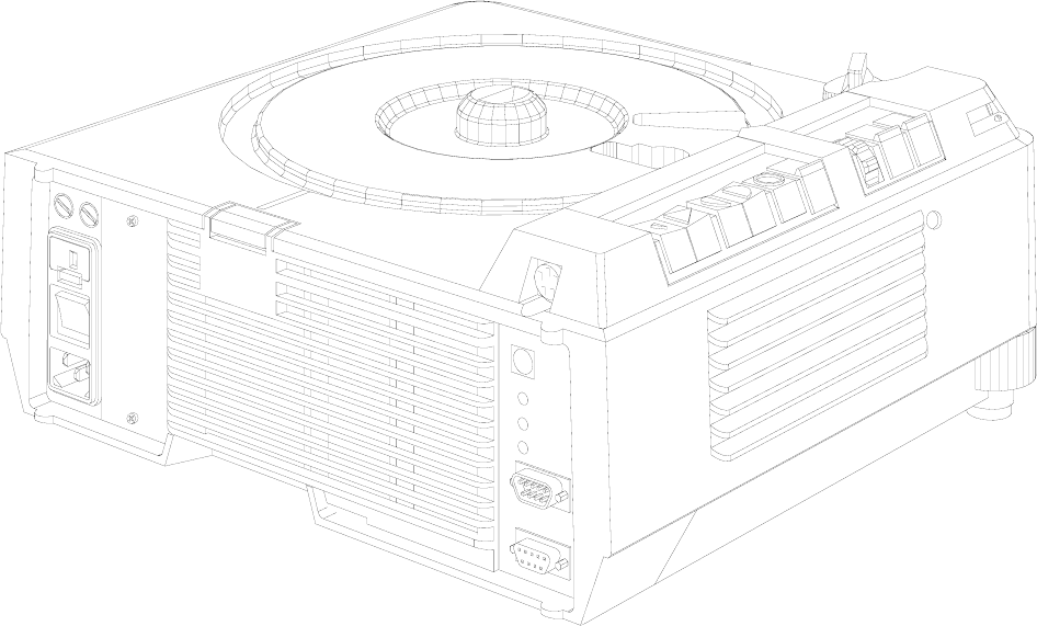
EKTAPRO Model 4020
Features and Functions:
Line voltages : 120/220/230/240V or 100/220VAC can be select with an
external VOLTAGE SELECTOR
Line frequency : 50/60 Hz
Power consumption : 380 W
Dual Lamp Module
Extra Bright: 35h EXR 82V/300 W
: 70h FHS 82V/300W
: 200h EXY 82V/250W
Slide change time : approx. 0,9s (single step)
: approx. up to 3s (random access)
Focus : Manual and electrically
Standby function : If the standby mode is activated the Keyboard will be disabled
Economy LAMP setting : 75% light output
No SLIDE No LIGHT function: Using an IR REMOTE CONTROL the keycode 550* will disable this
function, enter of the same keycode enables this function again
Slide Tray capability : 80/140 slides
Slide Tray Switch : After changing the switch position the Projector is running automatically
through a initialization procedure
figure 2-1
Service Manual SM 2547-1
03/98 2-2 Kodak AG, Stuttgart
EKTAPRO Model 4020
Adjustable Tray Motion : Tool PN 622 0454 has to used on Projectors from SN 85 xxx and
above
Manual elevator mechanism : Two height adjustment feet are attached on the front side of the
Projector
Indicator LED on front : LED continuously on Projector O.K. If the LED is blinking fast a slide
jam occurs. In standby mode the LED is blinking short off and long on.
If the LED is blinking continuously (on/off) a checksum error occurs
(only during programming the processor)
Remote SOCKET : 8 pin mini DIN
Slide change buttons : A single step will happen after pressing the “Forward" or the “Reverse”
button less than 0.9s. Multiple steps will be done by pressing the
“Forward”buttonmorethan0.9s
A run into the “Zero” position will immediately be done after press and
hold the “Reverse” button until the Slide Tray is in “Zero” position
Last Lamp used : After switching on the Projector the last used lamp will be selected
(memory function). This memory function can be disabled by pressing
the STANDBY button during switching on the projector
Line up : Pressing both transport keys will enable the lamp to adjust the projector
(green LED on the Backpanel is blinking). The Standby key will disable
this function
NEW
In case of using a IR Remote Control single steps are possible independent how long the button is pressed.
By pressing the “Reverse button” on the IR Remote Control random access is possible.
To select the Slide Tray capacity (80 or 140 slides) a ball point pen or a small screwdriver has to be used.
The Lamp Module has no longer a Heat Absorbing Glass installed. Due to the new mirror the light output is
increased up to 30%.
NOTE
In case of changing the mirror take care of the type (see NEWSLETTER #4).
SM 2547-1 Service Manual
Kodak AG, Stuttgart 2-3 03/98
EKTAPRO Model 5020
Features and Functions:
All features and functions of Model 4020
Additional:
AUTO FOCUS : Each slide will be focused, independent of the slide mount
Timer : Slide change can be set from 1 up to 60 sec.
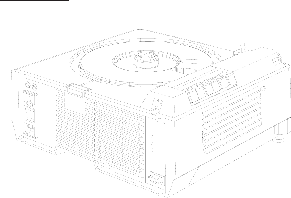
figure 2-2
Service Manual SM 2547-1
03/98 2-4 Kodak AG, Stuttgart
EKTAPRO Model 7020
Features and Functions:
All features and functions as Model 4020.
Additional features:
Application Slot : for Kodak and OEM ADAPTERS
Bus CONNECTORS (RS232): IN (female) and OUT (male)
Address Switch : 16 addresses can be selected
Initializing procedure : After power on the Projector the SLIDE LIFTER and the RING DRIVE
will be checked, the LAMP and the FAN will be switched off
High Light : 20% more light output, lamp life time approx. 30% reduced
NEW (only on Models 7020/9020)
If the parallel Mode “970*” is set on the IR Remote Control it is possible to toggle with “666*” between two
projectors to control the focus functions. These functions are only visible on the screen.
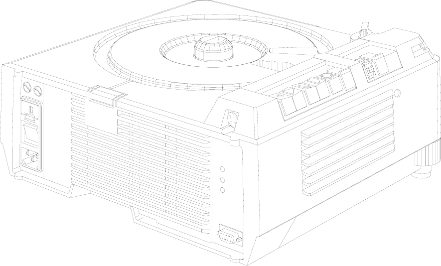
figure 2-3
SM 2547-1 Service Manual
Kodak AG, Stuttgart 2-5 03/98
EKTAPRO Model 9020
Features and Functions:
This multi purpose Projector has all of the features of the EKTAPRO 7020.
Additional features include:
AUTO-ZERO function: : When the Projector senses an empty, gate the Projector automatically
returns the tray to zero and begins the projection cycle again.
This function can be deenergized.
Timer : Slide change can be set from 1 up to 60 sec.
AUTO FOCUS : Same as in EKTAPRO 5020
High Light : 20% more light output, lamp life time approx. 30% reduced
NOTE (new Model EKTAPRO 920/CINE)
For special applications (cinema promotion) the Model EKTAPRO 920/CINE is available. This model has a
build in memory function which knows the last projected slide after switching off the projector.
Switching the projector on again the slide tray will run into that position after the initialization procedure.
If the timer is switched on at that time a soft dissolve will be started immediately.
New parts (NAMEPLATE and MICROCONTROLLER) see Illustrated parts list.
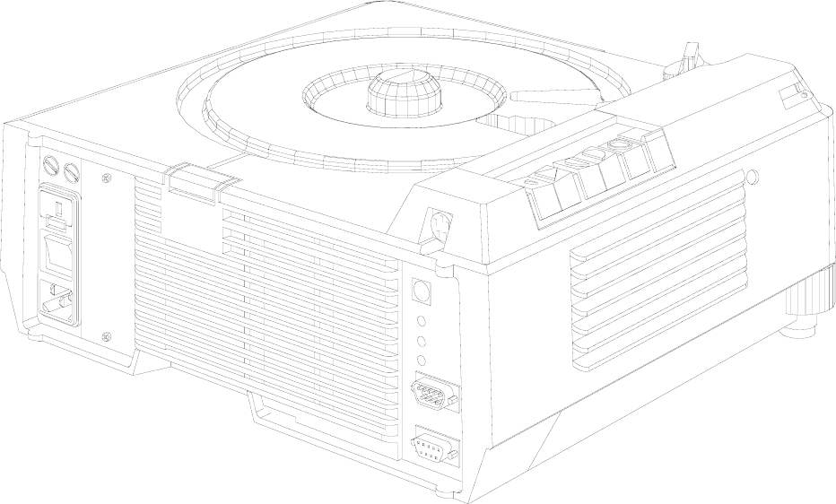
figure 2-4
Service Manual SM 2547-1
03/98 2-6 Kodak AG, Stuttgart

Overview
Model
FUNCTIONS/ACCESSORIES 4020 5020 7020 9020
DUAL LAMP MODULE (Extra BRIGHT) XXXX
TIMER -X-X
AUTO-ZERO ---X
ADDRESS SWITCH --XX
APPLICATION SLOT --XX
AUTO FOCUS -X-X
PRESENTATION BUS “IN” XXXX
PRESENTATION BUS “OUT” --XX
RANDOM ACCESS XXXX
EXTERNAL DIAGNOSTICS XXXX
12/7-PIN MODULE --OO
SLIDE SYNCHRONIZER (1000Hz) --OO
TWIN SOCKET OOOO
CABLE REMOTE OOOO
IR REMOTE SYSTEM RA OOOO
IR REMOTE SYSTEM RA/LP OOOO
X = Standard Feature O = Accessory - not possible
SM 2547-1 Service Manual
Kodak AG, Stuttgart 2-7 03/98
Accessories
DUAL LAMP MODULE
CAT No. 718 4369
CABLE REMOTE
CAT No. 712 1080
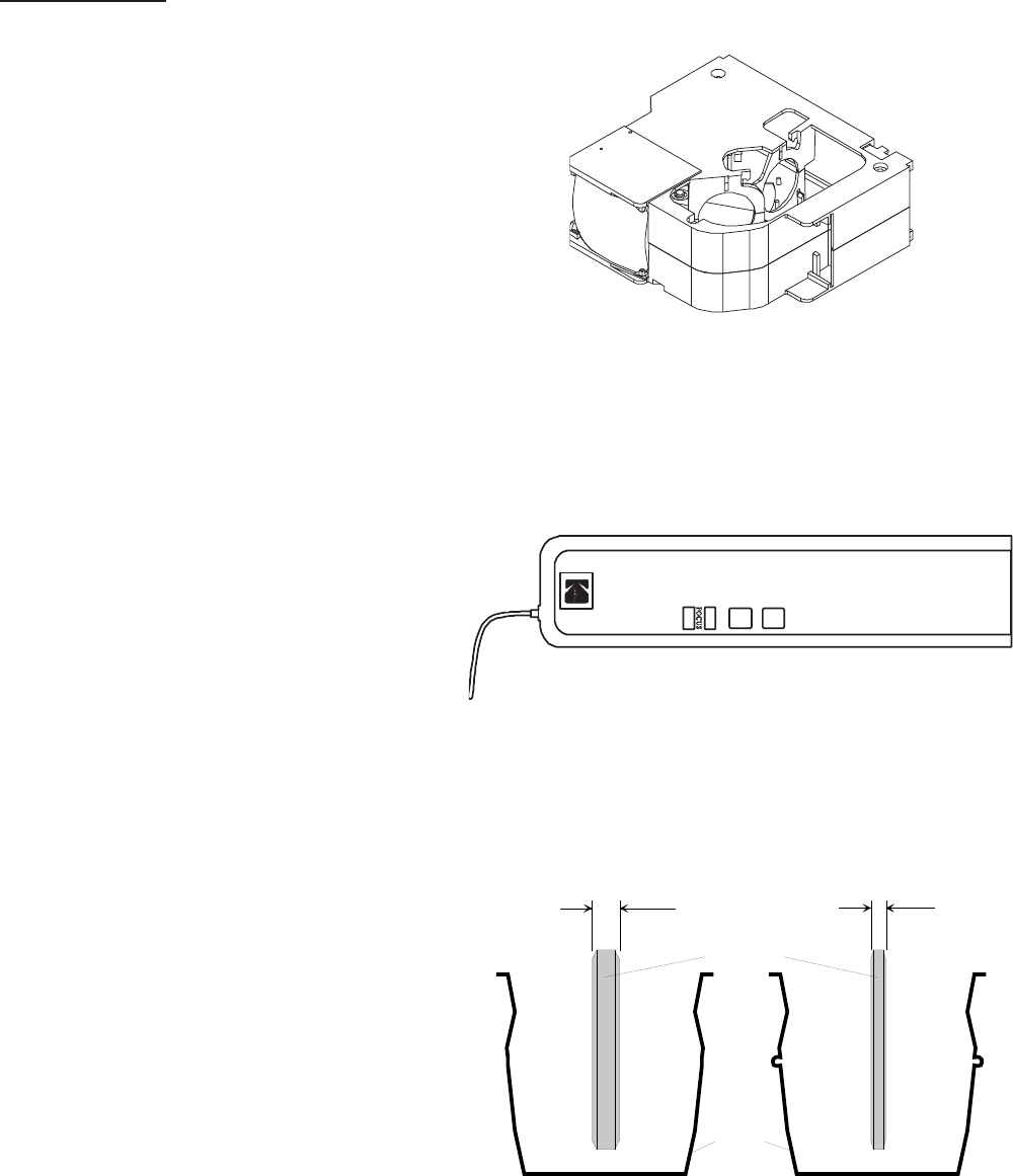
HEAT ABSORBING GLASS with CLIP
(not installed in Model 3020)
CAT No. 717 7140 (6mm thick)
CAT No. 717 7157 (3mm thick)
see NEWSLETTER #3/MAY/1996 page 5
figure 2-5
figure 2-6
6mm 3mm
CLIP
HEAT ABSORBING
GLASS
figure 2-7
Service Manual SM 2547-1
03/98 2-8 Kodak AG, Stuttgart
CONDENSER KIT 4X4 (with CLIP)
CAT No. 714 4967
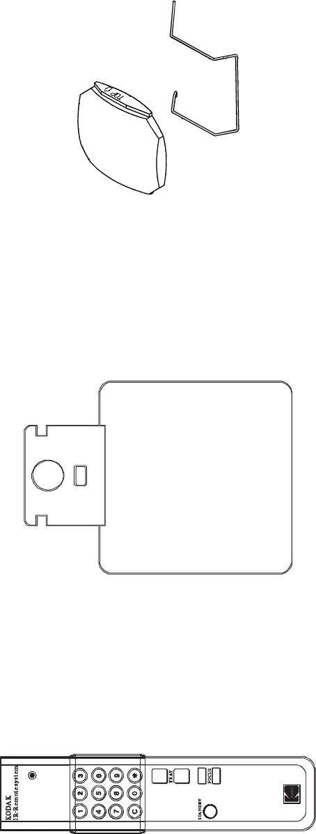
IR REMOTE System RA (with Random Access)
CAT No. 712 1072
complete with RECEIVER and TRANSMITTER
RECEIVER
TRANSMITTER
figure 2-8
figure 2-9
figure 2-10
SM 2547-1 Service Manual
Kodak AG, Stuttgart 2-9 03/98
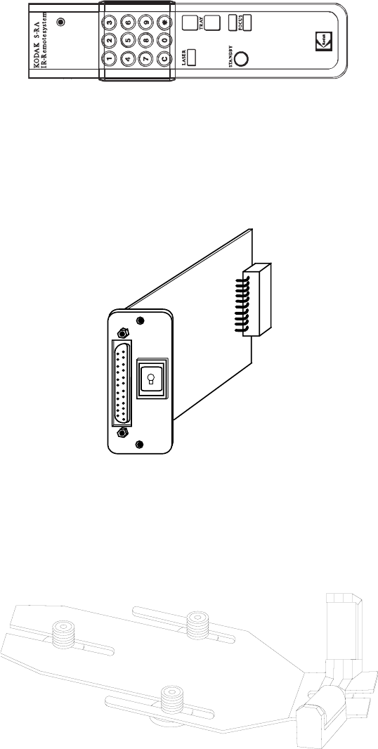
IR REMOTE System RA/LP (Laser Pointer)
CAT No. 712 1064 complete with RECEIVER
TRANSMITTER
RECEIVER as use with IR REMOTE System RA.
12/7-PIN MODULE
CAT No. 712 5875
LENS SUPPORT
CAT No. 715 1335
figure 2-11
Ext.
Int.
figure 2-12
figure 2-13
Service Manual SM 2547-1
03/98 2-10 Kodak AG, Stuttgart
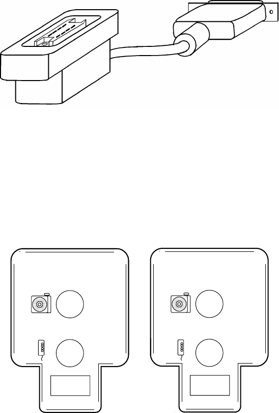
12/7-PIN ADAPTER CABLE
CAT No. 712 5883
TWIN SOCKET ADAPTER
CAT No. 712 5909
see NEWSLETTER #3/MAY/1996 page 7
figure 2-14
C
B
figure 2-15
SM 2547-1 Service Manual
Kodak AG, Stuttgart 2-11 03/98
SLIDE SYNCHRONIZER
CAT No. 712 5891 (not available)
see page 16 OEM ACCESSORIES
LAMPS
Catalog No. Description Lifetime
145 2259 EXR 82V/300 W life time about 35 hours
147 7678 EHS 82V/300 W life time about 70 hours
145 2143 EXY 82V/250 W life time about 200 hours
Service Manual SM 2547-1
03/98 2-12 Kodak AG, Stuttgart

Specification
Electrical Supply : 120/220/230/240 V
: or 100/220 V
: 50/60 Hz
Power Consumption : 380 W
Dimensions : 310 x 355 x 145 mm max. (l/w/h) with tray and lens
(12.2 x 14 x 5.7 in)
Weight : 6300 g (13.9 lb)
Slide size : 24 x 36 mm (0.9 x 1.4 in)
Slide change time : <0,8 s
Slide search time : <3 s
Slide temperature : 50°C (104°F) max. above room temperature
LAMP (standard) : EXR 82V/300W
Automatic LAMP change : 0.3 s
Operating temperature : 0°C to 40°C (32°F to 113°F)
Humidity : 20 to 85% r.H.
Air consumption : approx. 700 l/min. (20,000 cuft/min.)
Approvals : VDE, UL , CSA
Leveling : 0° to 18° with internal elevation mechanism 30° max. allowed
CONNECTORS
Remote SOCKET on Projector:
PIN No. Signal
112 VDC
2Gnd
3Signal 1 (LSB)
4Signal 2
5Signal 3
6Signal 4
7Signal 5 (MSB)
8Interrupt
12 V DC =
average value between 7.2 and 14.5 V DC
5
1
2
3
4
6
7
8
Type Mini DIN
(viewed from front )
figure 2-16
SM 2547-1 Service Manual
Kodak AG, Stuttgart 2-13 03/98
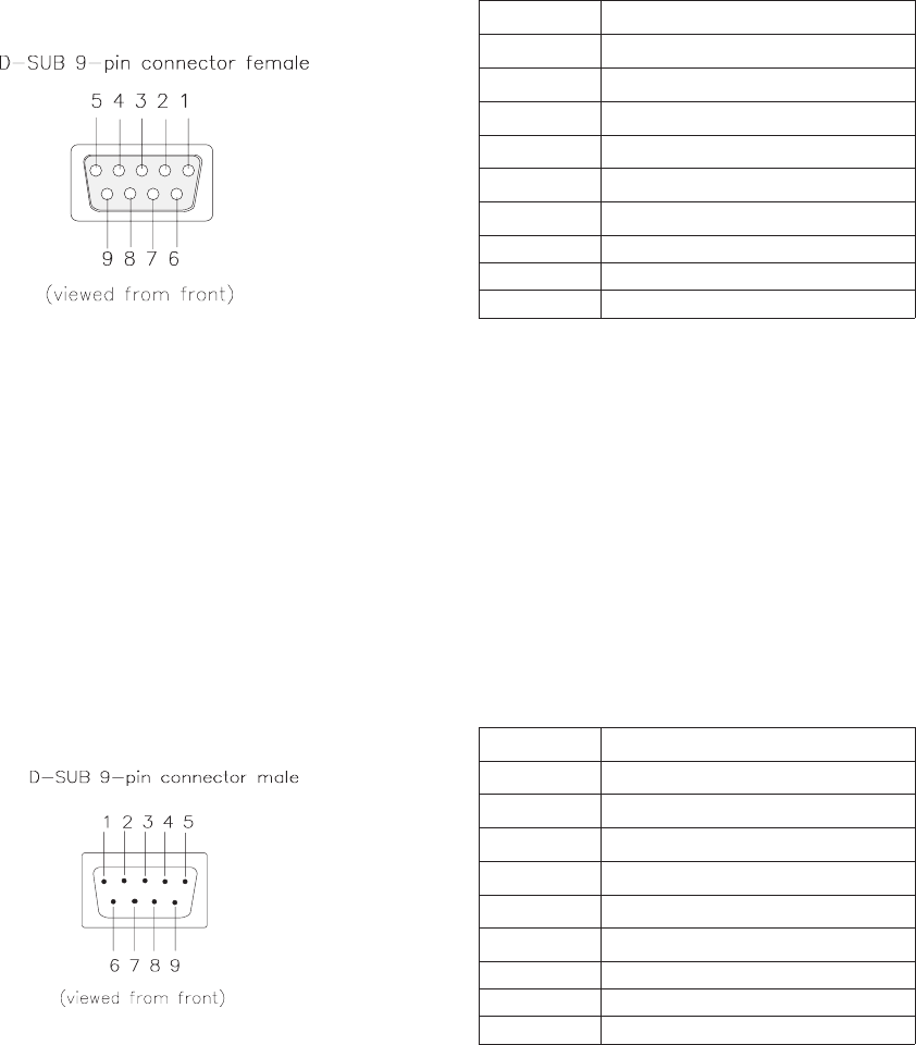
P-Bus / RS 232 “IN”
PIN No. Signal
1Connected to 4 and 6
2Receive Data (RxD)
3Transmit Data (TxD)
4Connected to 1 and 6
5Signal Ground
6Connected to 1 and 4
7-
8-
9-
P-Bus / RS 232 “OUT”
PIN No. Signal
1Connected to 4 and 6
2Transmit Data (TxD)v
3Receive Date (RxD)
4Connected to 1 and 6
5Signal Ground
6Connected to 1 and 4
7-
8-
9-
figure 2-17
figure 2-18
Service Manual SM 2547-1
03/98 2-14 Kodak AG, Stuttgart
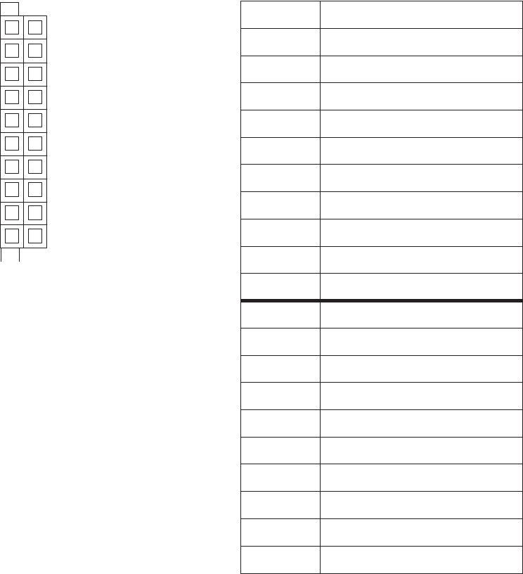
ACCESSORY SLOT
a
1
2
3
4
5
6
7
8
9
10
1
2
3
4
5
6
7
8
9
10
b
figure 2-19
PIN No. Signal
a1 SDA (I2C Data)
a2 I2C_INT (Interrupt)
a3 SLOT_232_R, TTL Level
a4 not used
a5 SLOT_A
a6 SLOT_C
a7 not used
a8 12V DC 200mA max.
a9 34V DC 750mA max.
a10 26V AC_N 750mA max.
b1 SLC (I2C Clock)
b2 PLL_DISS
b3 SLOT_232_T (TTL-Level)
b4 SLOT_DIS
b5 SLOT_B
b6 SL_DISS
b7 not used
b8 VSS 12 (Ground)
b9 VSS 34 (Ground)
b10 26V AC_L
SM 2547-1 Service Manual
Kodak AG, Stuttgart 2-15 03/98
OEM ACCESSORIES
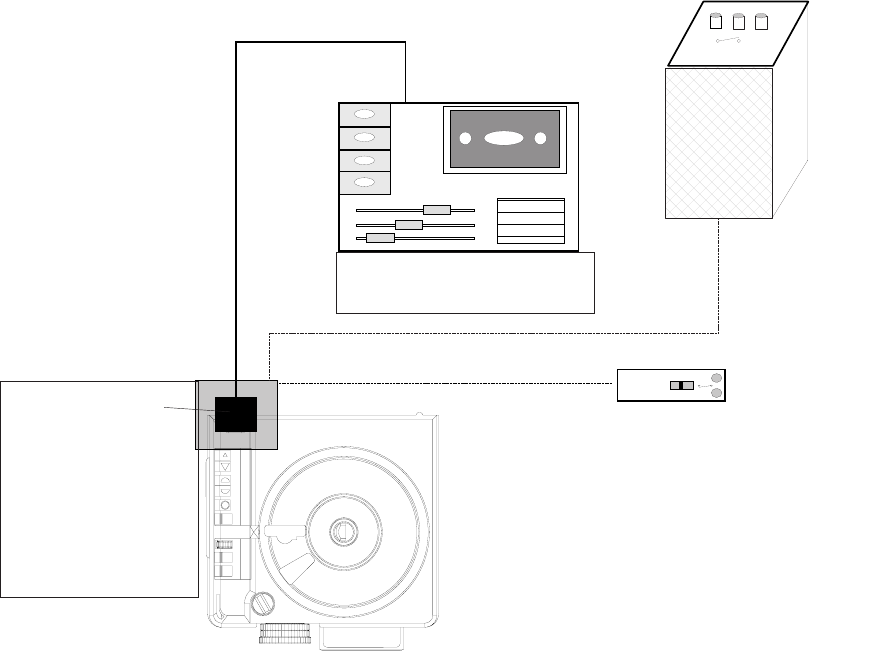
COPYRIGHT
The adapter of this English company is only designed to use traditional AV cassette recorders. Cue pulses
recorded on the tape trigger the interface unit to generate digital commands to advance the EKTAPRO Projector.
It is an interesting feature that the adapter works either by plugging directly into the remote socket or works
remotely by additional use of the EKTAPRO IR Receiver. In this case the system can simultaneously used with
both the EKTAPRO IR Transmitter and the adapter. The adapter is powered by a 9 volt A PP3 battery.
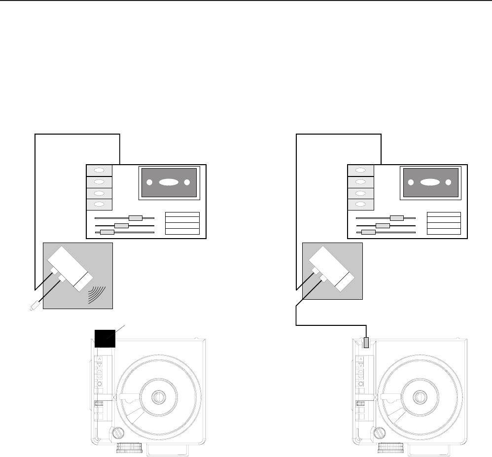
The illustration (figure 2-20) shows both possibilities to run the Projectors.
IR-USE.
The advantage is that the Adapter and Projector can be separated. In addition, the use of the
EKTAPRO Remote Transmitter is possible without disconnecting the Adapter.
CABLE USE
If no IR receiver is available the Adapter can be plugged with the fixed installed cable to the remote socket.
EKTAPRO IR Receiver
figure 2-20
Service Manual SM 2547-1
03/98 2-16 Kodak AG, Stuttgart
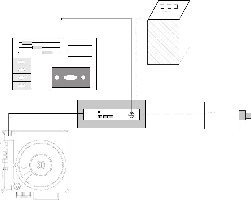
SLIDE SYNCHRONIZER ADAPTER by KODAK AUSTRALIA
Kodak Australia offers an own solution of a slide synchronizer adapter. This unit is built in the IR Receiver
housing and is therefor directly to be plugged onto the remote socket. A 6pin socket is built into the housing.
The system supports most of traditional AV cassette recorders. The S-AV cable remote can also be used with
the possibility to give transport commands and to focus. Speaker desk (lecterns) installations can be fully used.
The system is able to switch the Projector into the standby mode (press forward and reverse button
simultaneously) or run to the Projector to the zero position (press and hold down forward and reverse button).
NOTE
The S-AV Timer does not work on this adapter!
Speaker´s Desk
S-AV Remote Control
Professional AV Cassette
Recorder
EKTAPRO IR
Receiver Housing
with built in Slide
Synchronizer Adapter
figure 2-21
SM 2547-1 Service Manual
Kodak AG, Stuttgart 2-17 03/98
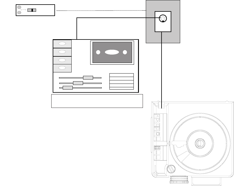
ADAPTER by MÜWO
The German company offers a slide synchronizer adapter which is built into the EKTAPRO Cable Remote
Control. A 6pin socket provides connection with external devices which are traditional AV cassette recorders,
S-AV Timer and speaker desks. Even if any devices are connected, the remote still works.
Professional AV
Cassette Recorder
S-AV Timer
EKTAPRO Remote Control
with built in Slide Synchronizer
Adapter
figure 2-22
Speaker´s Desk
Service Manual SM 2547-1
03/98 2-18 Kodak AG, Stuttgart
ADAPTERS by MAYER & ZELLER
The Swiss company Mayer & Zeller offers a 1000 Hz adapter which comes along in a small black plastic box
with a standard 6pin female receptacle and an integrated cable with the new 8pin male connector for the
EKTAPRO Projectors.
The adapter offers the possibility either to connect a traditional AV cassette recorder to advance the Projector
or
to connect the standard cable S-AV remote control or to use the cable already installed in the speakers desks.
The adapter is also offered in a special version which also enables the control of the focus via the remote control
(or speakers desks).
NOTE
The S-AV Timer cannot be used because of the lack of a support voltage . But Mayer & Zeller offers a
special Timer for controlling the EKTAPRO Projectors. The timer is built into the EKTAPRO Cable Remote
Control. This a quite sophisticated solution and an interesting offer for those who intend buying a cable
remote.
For further details contact the company.
S-AV Cable Remote Control
Professional AV Cassette Recorder
figure 2-23
SM 2547-1 Service Manual
Kodak AG, Stuttgart 2-19 03/98

ADDRESSES
CONTROL SYSTEMS
•ARION 701 South 7th Street Delano, MN 55328 USA
Tel: (001) 612 972 3351
Fax: (001) 612 972 3524
•Bässgen AV Technik GmbH Hauptstraße 58, 79104 Freiburg Germany
Tel: (0049) 761 23953
Fax: (0049) 761 35042
•Copyright Machines Limited 44/46 Sillwood Street Brighton, Sussex BNI 2PS UK
Tel: (0044) 273 720 175
Fax: (0044) 273 321 150
•Dataton AB Box 257 S-581 02 Linköping Schweden
Tel: (0046) 131 14325
Fax: (0046) 131 38445
•HEP Holland P.O.B. 33112, 3005 EC Rotterdam Niederlande
Tel: (0043) 10 418 3689
•Mechanische Weberei GmbH Neuhäuser Weg 2, 33175 Bad Lippspringe Germany
Tel: (0049) 52 52270
Fax: (0049) 52 522 7201
•Müwo electronic In den Maltwiesen 11, 72379 Hechingen-Stetten Germany
Tel: (0049) 7471 15830
•RMF Products Inc. P.O.B. 520, 1275 Paramount PKWY Batavia II, 60510 USA
Tel: (001) 708 879 0020
Fax: (001) 708 879 6749
•Stumpfl Rudigierstraße 8, A-4701 Bad Schallerbach Austria
Tel: (0043) 7249 2811
Fax: (0043) 7249 2811 18
•Zygo Systems Limited 48 Fallowfields Bicester Oxon OX67Qs UK
Tel: (0044) 869 248 261
Fax: (0044) 869 248 260
Service Manual SM 2547-1
03/98 2-20 Kodak AG, Stuttgart
SOFTWARE for direct PC CONTROL
•ARION 701 South 7th Street Delano, MN 55328 USA
Tel: (001) 612 972 3351
Fax: (001) 612 972 3524
•AVC Team Bieber Am Holling 3, 35649 Bischoffen Germany
Tel: (0049) 6444 1027
Fax: (0049) 6444 8527
•Martin Ballein Viktor Scheffel Straße 2, 74076 Heilbronn Germany
Tel: (0049) 7131 165170
Fax: (0049) 7131 52470
•Hilger & Bremen GbR Heinzenstraße 20, 52062 Aachen Germany
Tel: (0049) 241 49797
Fax: (0049) 241 49787
•Holidays Afloat Limited Schachterij 9920 Lovendegem Belgium
Tel: (0032) 9372 8908
Fax: (0032) 9233 5609
•Stumpfl Rudigierstraße 8, A-4701 Bad Schallerbach Austria
Tel: (0043) 7249 2811
Fax: (0043) 7249 2811 18
•Peter Ziegler Van Gogh Platz 6, 53844 Troisdorf Germany
Tel: (0049) 2241 46143
RACKS
•Chief Manufacturing Inc. 14310 Ewing Avenue South Burnsville MN 55337 USA
•Roha Projektionstechnik Bruno Jacoby Weg 11, 70597 Stuttgart Germany
Tel: (0049) 711 723 621
Fax: (0049) 711 23699
EXTERNAL TIMER
•Mayer & Zeller Wettsteinallee 15, 4058 Basel Switzerland
Tel: (0041) 61681 4343
Fax: (0041) 61681 3907
•Müwo electronic In den Maltwiesen 11, 72379 Hechingen-Stetten Germany
Tel: (0049) 7471 15830
•Wintron GmbH Egilolfstraße 70, 70599 Stuttgart Germany
Tel: (0049) 711 4567 258
Fax (0049) 711 4567 267
SM 2547-1 Service Manual
Kodak AG, Stuttgart 2-21 03/98
blank page
Service Manual SM 2547-1
03/98 2-22 Kodak AG, Stuttgart
3. THEORY GUIDE
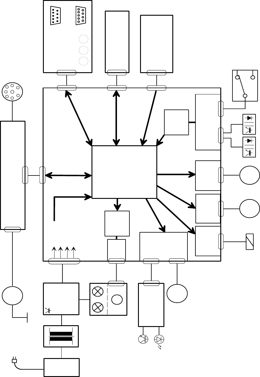
Block Diagram
All functions of the projector are controlled by the MICROCONTROLLER ( MC68HC016B with 16k ROM) on the
MASTER PCB.
The controlling software is loaded in the 16k ROM of the MICROCONTROLLER for Models 4020 - 9020 and
9020/CINE.
Located around the MICROCONTROLLER on the MASTER PCB there are the inputs, outputs and drivers for
the sensors, LAMP, MOTOR´s and other functions.
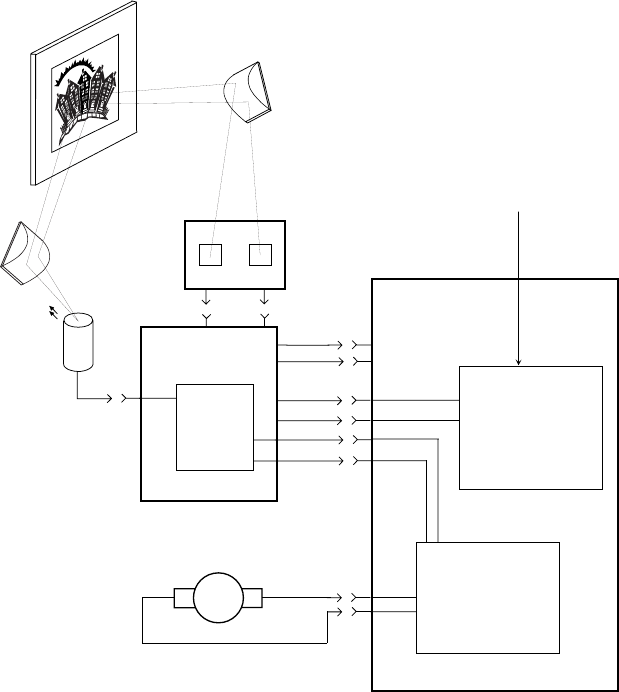
The block diagram (figure 3-1) shows all of the functions of Model 7020 and 9020.
All model is equipped with the same MASTER PCB´s.
MODEL MASTERBOARD MICROCONTROLLER
4020 LAYOUT No.7 Version 4.8
5020 LAYOUT No.7 Version 4.8
7020 LAYOUT No.7 Version 4.8
9020 LAYOUT No.7 Version 4.8
9020/CINE LAYOUT No.7 Version 4.9
SM 2547-1 Service Manual
Kodak AG, Stuttgart 3-1 03/98
Dual Lamp
Module
Power and
Lamp
Regulation
Line
Switch
Fuse
Accessory Slot
Tray Motion
PCB
Driver
M
5V DC
12V DC
26V DC
36V DC
M
Mirror Motor
Focus
Control
MICRO
CONTROLLER
Autofocus
PCB
Input
Mirror
Driver
Transformer
Back
Panel PCB
Keyboard PCB
Driver
M
Driver
MASTERBOARD
M
Focus Motor
Remote Socket
Shutter
Solenoid
Tray
Motor
Gate
Sensor
CAM
Sensor
Slide Lifter
Motor
M
Fan
Software
Lamp
Control
Tray
Size
MASTERBOARD Model 4020 - 9020 (9020/CINE)
Software
Slide in
Gatel
figure 3-1
Service Manual SM 2547-1
03/98 3-2 Kodak AG, Stuttgart
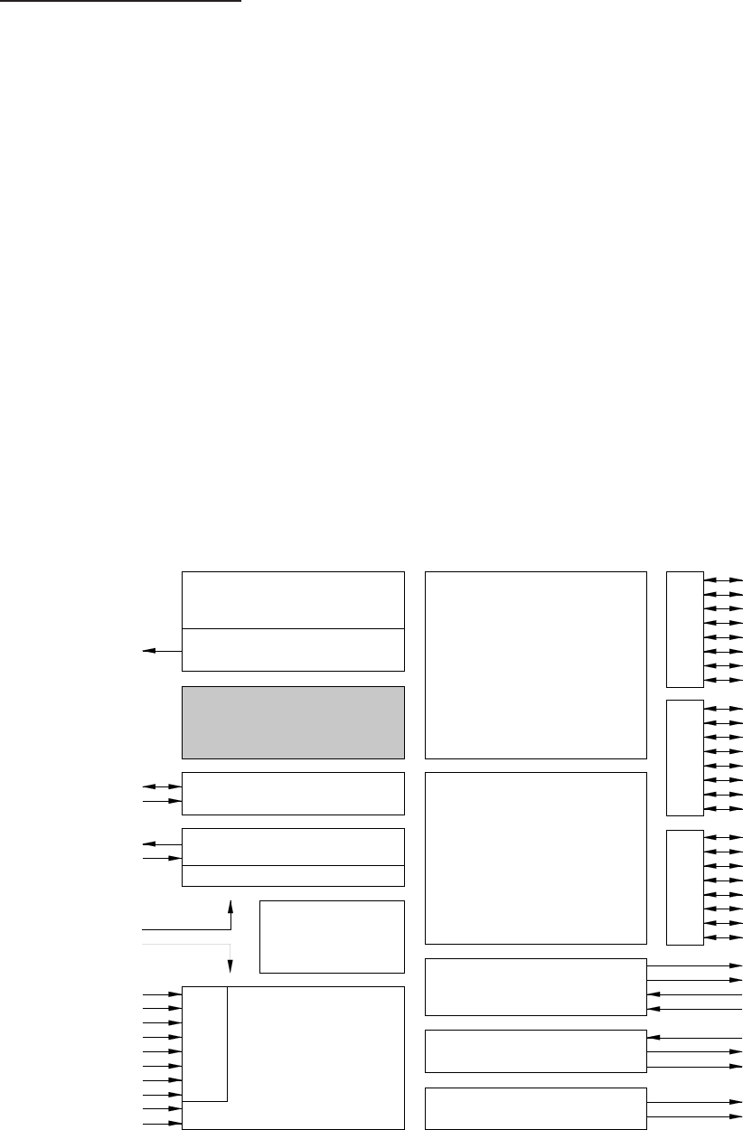
Microcontroller Unit
The main device on the MASTER PCB is the 16-bit MICROCONTROLLER unit MC68HC05B16 from
MOTORola
for the models EKTAPRO 4020 - 9020 and 9029/CINE
This MICROCONTROLLER has a microprocessor, timer, memory, analog/ digital converter and input/output ports
on one chip. Compared to a standard processor, where for each item a peripheral IC is necessary.
This MICROCONTROLLER with its on-chip software controls all functions of the projector plus peripheral circuits.
The main features of the MICROCONTROLLER are:
- 24 bi-directional I/O lines
- 8 input-only lines
- serial communication interface system
- 8 channel A/D converter
- 15120 Bytes ROM (Models 4020 - 9020 and 9020/CINE)
- 2 channel timer
The following block diagram shows the internal MICROCONTROLLER functions.
PA0
PA1
PA2
PA3
PA4
PA5
PA6
PA7
PB0
PB1
PB2
PB3
PB4
PB5
PB6
PB7
PC0
PC1
PC2/ECLK
PC3
PC4
PC5
PC6
PC7
TCMP1
TCMP2
TCAP1
TCAP2
RDI
SCLK
TDO
PLMA D/A
PLMB D/A
PD0/AN0
PD1/AN1
PD2/AN2
PD3/AN3
PD4/AN4
PD5/AN5
PD6/AN6
PD7/AN7
VRH
VRL
VSS
VDD
OSC1
OSC2
IRQ
RESET
VPP1
PORT APORT B
PORT D
PLM
SCI
352 bytes
static RAM
496 bytes
self check ROM
256 byte
EEPROM
MC68HC05B16 (15120 bytesROM)
Model 4020 - 9020 and 9020/CINE
Charge pump
COP watchdog
Oscillator
÷2 / ÷32
M68C05
CPU
8-bit
A/D converter
16-bit
timer
PORT C
figure 3-2
SM 2547-1 Service Manual
Kodak AG, Stuttgart 3-3 03/98

Description of Functions
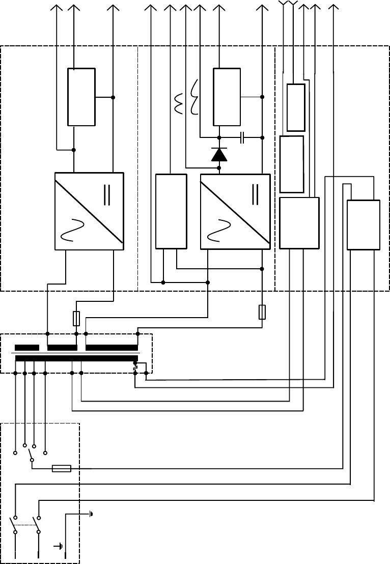
Power Supply
The PROJECTOR POWER SYSTEM consists of a
•POWER INPUT ASSEMBLY with POWER ON/OFF SWITCH, PRIMARY FUSE HOLDER
and VOLTAGE SELECTOR
•TRANSFORMER, SECONDARY FUSE HOLDER
•POWER REGULATION PCB
The TRANSFORMER supplies the following voltages:
Primary voltage outputs:
92/81 VAC LAMP voltage for Models 4020 - 9020 and 9020/CINE (SOFTWARE CONTROLLED
LAMP CURVE)
Safety Extra Low Voltage outputs:
10 VAC for +5V DC and +12V DC
26 VAC for 36 VDC regulated and unregulated,
The POWER REGULATION PCB contains:
- line EMI filter
- rectifiers and regulators
- Triac LAMP Software Control Circuits (Models 4020 - 9020 and 9020/CINE)
The output voltages and signal are:
- 36 VDC unstabilized (36 VDC_12P) for slot interface
- 36 VDC capacitor- stabilized (36 VDC) for MOTOR´s, solenoid, fan
- 12 VDC unregulated for remote control and slot
- 5 VDC regulated for logic and MICROCONTROLLER
- 26 VAC for accessory slot
- Zero_cross signal for synchronization of the dissolve feature
Details can be obtained from circuit diagrams and the following block diagram.
IMPORTANT
Connect all the equipment to the same same power line, otherwise phase shifting will bring up problems !
Service Manual SM 2547-1
03/98 3-4 Kodak AG, Stuttgart
Power Regulation BoardPower Module
Fuse
Voltage Selector
Switch
L
N
)
)
)
Black
Red
White
Gray
Regulator
Regulator
Line
Filter
Zero Cross
Circuit
10V
26V
Blue
12V DC
5V DC
V
SS
26V AC_FL
Zero_Cross
36V DC_12P
36V DC
15V DC
Triac
Relay
Lamp1
Lamp2
Neutral
V
SS
240
230
220
120
91
82
1.25A
2A
USA 2.8A
Economy
Normal
Triac Relay
figure 3-3
SM 2547-1 Service Manual
Kodak AG, Stuttgart 3-5 03/98
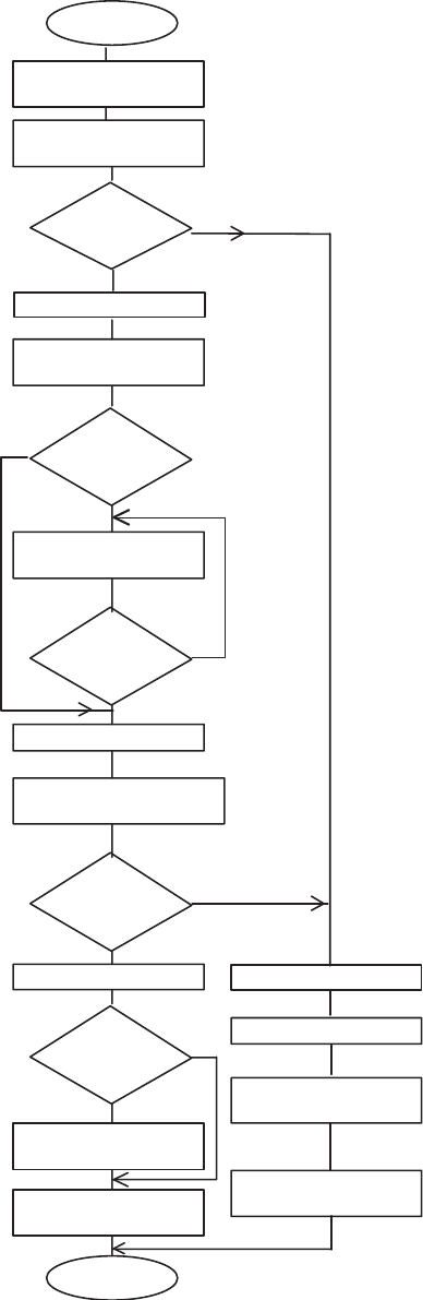
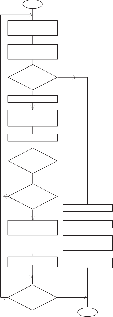
Switch On / Initialize Procedure
Projector Status: Mechanic position is not known
Projector is energized
The MICROCONTROLLER starts the initialization routine:
- load the look-up tables
- look at the accessory slot and projector address
- sets the ECONOMY LAMP RELAY to 82V
- completes a Hardware reset
SLIDE LIFT MOTOR rotates clockwise (max. of 805 steps = one SLIDE
LIFTER cycle).
If SENSOR SIGNAL changes from not actuated to actuated, the SLIDE
LIFTER is in up position.
Yes = Start tray MOTION.
No = Begin a failure routine, after it has advanced 805 steps without
sensor signal change.
slide tray moves forward about 3,5 slides (with software version above
4.2).
Details about tray motion can be obtain from page 3-9.
If the ZERO SENSOR is not actuated, the tray reverses
If the ZERO SENSOR is not actuated, the slide tray continues to
advance.
The SLIDE LIFT MOTOR moves clockwise.
When the CAM SENSOR changes from actuated to not actuated, the
LIFTER is in the down position.
If the SLIDE IN GATE SENSOR is actuated, the SHUTTER opens.
No
Yes
No
START
Microcontroller
is active
Slide LIFT MOTOR On.Move
LIFTER to Up Positon
CAM Sensor
Signal
0 - 1
Move Slide Tray
about 3 Slides forward
Zero
Sensor actuated
?
Reverse Slide Tray
Zero
Sensor actuated
?
Stop Tray Motor
Slide LIFT MOTOR On
Slide LIFTER to Down Positon
CAM Sensor
Signal
1 - 0
Slide in Gate
Sensor actuated
?
Open Shutter
Autofocus On
Projector Ready
for Operation
END
Stop LIFT MOTOR
Power LED Blinking
Write the Failure into
Memory
Projector does not
Operate
Stop LIFT MOTOR
No
Yes
No
Yes
Yes
No
Yes
No
Stop LIFT MOTOR
figure 3-4
Service Manual SM 2547-1
03/98 3-6 Kodak AG, Stuttgart
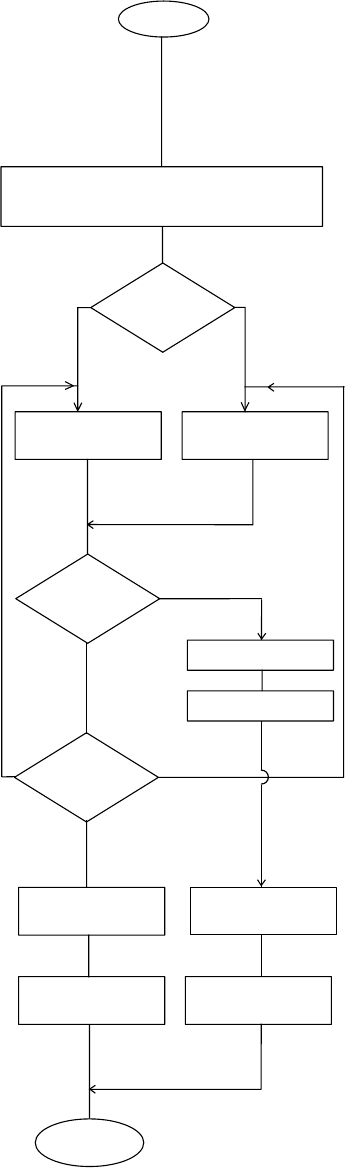
Slide Change Sequence
Projector Status:
- SLIDE LIFTER down
- SHUTTER is open
- SLIDE is in GATE
- LAMP is energized
Start: “Forward”/"Reverse" BUTTON is pressed.
Signal from: P-Bus, Remote Control or Timer
The SHUTTER SOLENOID is deenergized.
The SLIDE LIFT MOTOR rotates clockwise to move the SLIDE LIFTER
up (max. 805 steps = one SLIDE LIFTER cycle).
The SLIDE LIFTER is in the up position when the CAM SENSOR
signal changes from not actuated to actuated.
If no: the failure routine begins after 805 steps a without signal change.
If yes: Starts the tray Motion. See page 3-10.
For details see page 3-10.
The SLIDE LIFT MOTOR moves clockwise to move SLIDE LIFTER
down. The MOTOR stops when signal changes from actuated to not
actuated.
When a TIMER is in use, a slide advance forward is done each time
after the selected interval is reached (Model´s 4020, 7020 external
timer, Model 5020, 9020 and 9020/CINE internal timer).
The slide is projected.
START
Close Shutter
Switch Autofocus Off
CAM
Sensor Signal
0 - 1
?
Yes
No
max. 805 Steps of
Slide Lift Motor
Start Tray Motion
Next slide position
Slide Lift Motor On
Slide
in Gate Sensor
actuated
?
Yes
No
Switch on Autofocus
Open Shutter
Timer
activated
?
Yes No
End
Power LED blinking
Slide Lift Motor off
CAM
Sensor Signal
1 - 0
?
Yes
No
Slide Lift Motor off
Projector does not
operate
Write Failure into
Memory
figure 3-5
SM 2547-1 Service Manual
Kodak AG, Stuttgart 3-7 03/98
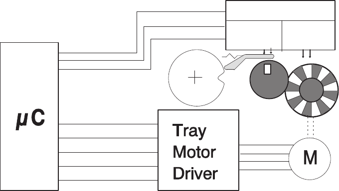
Tray Motion
The STEPPER MOTOR is responsible for the slide tray movement. To move the tray one slide forward or reverse
47 steps are necessary in case a tray for 80 slides is used and 27 steps in case a tray for 140 slides is used.
The tray movement is controlled by the TRAY MOTION CONTROL PCB. This PCB contains two optical sensors,
one for the code wheel and one for the Zero Position Gear.
This PCB is sending following feedback signals to the MICROCONTROLLER:
- Tray motion direction (forward or reverse)
- One pulse for each step of the STEPPER MOTOR
- Tray zero-position signal in case the tray is in the zero position
If the STEPPER MOTOR moves one step, a pulse will be send back from the TRY MOTION PCB to the
MICROCONTROLLER after the step is done.
If these pulses are missing, the MICROCONTROLLER assumes that the tray is not able move. The transport
stops immediately. A failure code is written into memory, the projector do not operate, the power LED is blinking
The projector must be deenergized. The jam must be cleared. As soon as the problem is solved, the projector
should operate after switching on again.
The DIRECTION + STEP SENSOR is a special optical device which generates two independent output signals:
- step pulses (count signal for the MICROCONTROLLER to calculate the tray position)
- direction signal (low signal for forward steps and high signal for reverse steps)
Tray Control PCB
Direction
+ Step
Sensor
Zero-Pos.
Sensor
Tray Zero
Direction
Tray Step
Slide
Tray
figure 3-6
Service Manual SM 2547-1
03/98 3-8 Kodak AG, Stuttgart
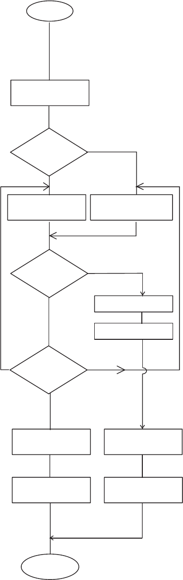
Tray Motion Sequence:
a) Go To Zero Position Projector Status: - Energized
Signal from: - P-Bus (Model´s 4020 and 5020 input only)
- Auto Zero (Model 9020 and 9020/CINE)
The MICROCONTROLLER selects shortest distance to the zero
position.
The TRAY MOTOR is energized.
The TRAY MOTION CONTROL delivers a step signal for each MOTOR
step.
The ZERO SENSOR delivers a signal if the position is reached
Failure: A failure code is written into memory.
The power LED is blinking.
The position is reached. The TRAY POSITION in memory set to zero.
Close Shutter, Autofocus off, Move Slide
LIFTER in up position
Shortest
distance to Zero
?
Yes
NoNo
Zero Sensor
actuated
?
Stop Tray Motor
Slide LIFTER Down
Set Tray Position
to Zero
END
Tray Motor ON
Reverse
Tray Motor On
Forward
More than
4 Step Signals
missed ?
No
Yes
Transport Failure
Write failure
into Memory
Projector does
not Operate
Zero Button
Power LED Blinking
figure 3-7
SM 2547-1 Service Manual
Kodak AG, Stuttgart 3-9 03/98
b) Go to next slide position
Projector Status: There is a slide in the gate and it is projected.
Start action: The forward or reverse BUTTON is actuated
or next slide is selected with RANDOM
ACCESS.
See Slide Change Sequence, page 3-7.
RANDOM ACCESS: The MICROCONTROLLER selects shortest
distance to the next slide.
The MICROCONTROLLER energizes the TRAY MOTOR for 47 steps
(80 tray) or 27 (140 tray) for each slide.
The MICROCONTROLLER checks feedback from tray MOTION
CONTROL CIRCUIT.
If more than 4 feedback pulses are missed, exit to the failure routine.
For RANDOM ACCESS: The TRAY MOTOR ON until the position is
reached.
For FORWARD/REVERSE BUTTONS:
- tray moves only for one slide
- slide is projected
- if transport button is still pressed,
a slide is lifted up and the tray moves until button is released but
stops at the ZERO POSITION.
The MICROCONTROLLER sets the next position into memory.
The SLIDE LIFTER Down procedure starts.
For details, see Slide Change Sequence.
Yes
No
No
Set Tray Position
to next slide position
END
Tray Motor reverse
Tray Motor forward
More than
4 Step Signals
missed
?
No
Yes
Transport Failure
Write failure
into Memory
Projector
inoperable
requested
Position
reached
?
Start
Slide LIFTER Up
Next Slide
Position
?
Slide LIFTER down
Slide projected
forwards
Power LED Blinking
reverse
figure 3-8
Service Manual SM 2547-1
03/98 3-10 Kodak AG, Stuttgart
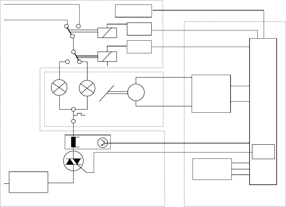
LAMP Control
a) Dual LAMP Operation
All Models are equipped with a DUAL LAMP MODULE (Extra Bright).
The POWER REGULATION PCB on all Models contains a LAMP current circuit that can detect if the active
LAMP is on, indicated by a LED on the BACK PANEL.
If a LAMP fails, the MICROCONTROLLER receives the LAMP_CURR signal from the POWER REGULATION
PCB. It activates the MIRROR MOTOR and moves the MIRROR to the second LAMP position. Then the relay
K1 is energized and second LAMP is energized. The MICROCONTROLLER also energizes the LED for the
second LAMP. The LED’s are located on the BACK PANEL.
The Models 4020 - 9020 and 9020/CINE have a memory. This memory is storing the the current used lamp as
long as the lamp is defective. That means the mirror of the DUAL LAMP MODULE do not change his position
after a new lamp is inserted. This function can be disabled (see page 2-3).
The characteristic of the lamp curve is no longer generated by a PLL circuit on the MASTERBOARD. Up to
now it is stored in the Software LAMP Control memory and the TRIAC will be triggered from the
MICROCONTROLLER.
Zero-Cross
Circuit
M
Mirror
Motor
Dissolve
Logic
Relay
Mirror
Motor
Driver
Micro
Controller
Master Board
Dual Lamp
Modul
Power Regulation Board
91VAC
Lamp Current
Detection and
Switch off
Relay
Driver
L1
L2
Zero_Cross
DATA
SYNC
Lamp_curr
Lamp
Current
Relay
Driver
Economy
82VAC
Software
Lamp
Control
SOFTWARE TRIGGER
GND
figure 3-9
SM 2547-1 Service Manual
Kodak AG, Stuttgart 3-11 03/98
b) LAMP setting
Models 4020 - 9020 and 9020/CINE:
a) Through the LAMP SWITCH or P-Bus
The settings of the LAMP are change by using the LAMP dimming function through the TRIAC
DISSOLVE LOGIC. The phase cut position for LOW is 75% of HIGH .
The LAMP supply voltage is 91 VAC only.
Resulting LAMP voltages: Standard: 82V RMS
Economy : 72V RMS
b) Via accessory slot
External units that are connected to the accessory slot cannot use the Standard/Economy LAMP
setting with phase cut. Therefore, the LAMP supply voltage is switched with the ECONOMY
SIGNAL and a relay to 82 VAC.
The functions of the STANDBY and Standard/Economy Buttons are disabled.
c) LAMP Protection
In the LAMP RETURN LINE on the POWER REGULATION PCB there is a small circuit that detects the actual
LAMP current.
LAMPS can explode when they reach the end of their life. The melting filament can create a short circuit with a
high current.
The high current is detected, and the LAMP is deenergized immediately by the TRIAC.
This procedure prevents the LAMP from exploding, and protects the TRIAC.
d) LAMP Voltage Control
All Models are equipped with a LAMP voltage regulation so that the LAMP voltage does not follow line voltage
fluctuation. The 5V AC outlet of the POWER REGULATION PCB i used to create the VAC_Value signal on the
MASTER PCB. This signal is fed to the MICROCONTROLLER (MC). The MC then selects a phase cut position
of the LAMP voltage which results in a reasonable constant LAMP voltage. This function is disabled if an
accessory is connected to the accessory slot. In this case the LAMP operates with 82 VAC.
Service Manual SM 2547-1
03/98 3-12 Kodak AG, Stuttgart
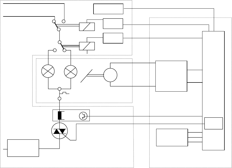
e) Lamp Dimming
The LAMP DIMMING FUNCTION is installed in Model 4020 - 9020. It is used for dissolving for Economy and
Standard LAMP settings. The main devices for dimming are the TRIAC, TRIAC CONTROL and Zero_Cross
circuit on the POWER REGULATION PCB, the dissolve logic and the MICROCONTROLLER (MC) on the
MASTER PCB.
The TRIAC FUNCTION is controlled by the MICROCONTROLLER and its software, it works according to phase
cut principals.
Zero-Cross
Circuit
M
Mirror
Motor
Dissolve
Logic
Relay
Mirror
Motor
Driver
Micro
Controller
Master Board
Dual Lamp
Modul
Power Regulation Board
91VAC
Lamp Current
Detection and
Switch off
Relay
Driver
L1
L2
Zero_Cross
DATA
SYNC
Lamp_curr
Lamp
Current
Relay
Driver
Economy
82VAC
Software
Lamp
Control
SOFTWARE TRIGGER
GND
figure 3-10
SM 2547-1 Service Manual
Kodak AG, Stuttgart 3-13 03/98
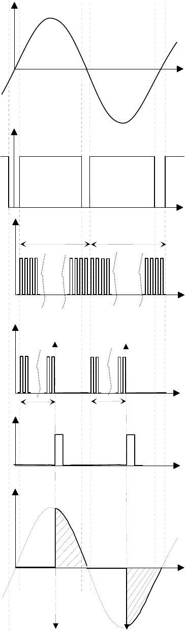
The zero-cross circuit creates an impulse whenever the LAMP
voltage crosses the zero line (LAMP voltage close to zero).
Seefigureb.
Therefore, every 10ms for 50Hz or 8,3ms for 60Hz a signal
change occurs. This signal is sent to the DISSOLVE LOGIC on
the MASTER PCB. The DISSOLVE LOGIC generates a
clocksignal with 4096 pulses for the length of half a sine wave.
This clock signal is triggered by the zero-cross signal.
Seefigurec.
Through the DATA SIGNAL, the MICROCONTROLLER delivers
a value between 3 and 3700 to the DISSOLVE LOGIC. Values
of 0 to 4096 are possible, but these valves would cause
false phase cut positions because the zero-cross signal does not
detect zero on the sine wave.
At the next zero-cross of the LAMP voltage, the DISSOLVE
LOGIC reads the value in the MICROCONTROLLER. This value
can range from 0 to 1000, and is counted by internally generated
clock signal. The clock signal sends the TRIAC TRIGGER signal
to the TRIAC CONTROL on the POWER CONTROL PCB.
The TRIAC is energized and the LAMP is energized for the rest
of that half sine wave.
If the MICROCONTROLLER sends a new value, the next half
would have a different phase cut position. If the value is not
changed, the cut position leaves unchanged.
The LAMP dissolve function operates between zero and high
with an accessory in the accessory slot or with RS232. High or
low on the LAMP is controlled by the BRIGHTNESS SWITCH.
The dissolve range of zero to full brightness is divided into 1000
steps. These steps can be used to create a linear LAMP
brightness change.
A lookup table is used in the MICROCONTROLLER software.
This table contains the corresponding phase cut value for each
one of the 1000 steps for a linear brightness setting.
4096 Pulses
a) Lamp Voltage
b) Zero-Cross Signal
4096 Pulses
c) Internal Counter Clock Signal
d) Example
1000
0
0
1000
e) Trigger Impuls
d) Actual Lamp Voltage
figure 3-11
Service Manual SM 2547-1
03/98 3-14 Kodak AG, Stuttgart
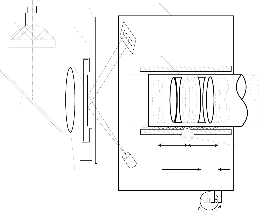
Focus
There are different possibilities to get a crisp and clear focused image on the screen.
1. Use the FOCUS KNOB. In this case the LENS will be moved inside the LENS CARRIER, while the LENS
CARRIER still keeps his position.
2. Use the FOCUSING BUTTONS either on the KEYBOARD of the PROJECTOR or on the REMOTE
CONTROL. In this case the LENS and the LENS CARRIER are moving together. The focus range
is limited, and depend on the ECCENTRIC of the FOCUS MOTOR (approx. 8mm / 0.3 in.).
Mirror
Shutter
Lens Carrier
IR-Receiver
IR-
Transmitter
Slide Gate
Lens
Manual
Focus Knob
Focus
Motor
T1
T2
Manual
Focus Range
Autofocus
Range approx.
8mm (0.3in)
Lamp
Slide
Surface
Kondensor Lens
figure 3-12
SM 2547-1 Service Manual
Kodak AG, Stuttgart 3-15 03/98
AUTO FOCUS
The AUTO FOCUS feature is installed in the EKTAPRO Model 5020,9020 and 9020/CINE.
A “low” FOCUS EXT signal from the MICROCONTROLLER enables the AUTO FOCUS PCB while a “high” signal
disables the AUTO FOCUS to ensure a sharpness correction for the projected slide. If a manual sharpness
correction was necessary the AUTO FOCUS MOTOR moves back to its primary position after the next slide
change. The AUTO FOCUS MOTOR is running until both receivers has the same light input. The FOCUS
MOTOR stops at the time the light input on both Photo transistors is equal. The direction for the focus movement
is defined by either receiver port 1 or port 2.
An electronic circuit will determine the operating voltage for the FOCUS MOTOR (running forwards or backwards)
to ensure to have the same speed in both directions. This regulation is necessary because the LENS CARRIER
is basic loaded with a spring in one direction.
To ensure that the AUTO FOCUS function works properly it is very important to use the same kind of slide
frames. Mixing up glass slides with other slides will bring the projected image out of focus because there is only
one reference point for the lens position to get a sharp and clear projected image on the screen.
If glassless slide frames are in use, it could be, that the borders of the projected image are out of focus.
It depends on the IR-Beam which is only sensing the center of the slide.
MASTER
BOARD
AF
BOARD
M
FOCUS
LOGIC
Slide
Prism
IR-
Receiver
IR-
Trnasmitter
Focus Motor
Prism
Focus Command
from Keyboard or
Remote Control
T1 T2
5V DC
GND
Foc Ext2
Foc Ext1
Speed
Direction
FOCUS
MOTOR
CONTROL
MICRO
CONTROLLER
figure 3-13
Service Manual SM 2547-1
03/98 3-16 Kodak AG, Stuttgart
P-BUS
All the Models are equipped with the P-Bus feature.
The Models 4020 and 5020 has only an Input Bus, Models 7020 and 9020 and 9020/CINE an IN/OUT Bus.
The P-Bus (Presentation Bus) is a serial asynchronous data transmission interface which uses the RS 232 /
V.24/ V.28 standard. This type of interface is used with Personal Computers for external communication.
The purpose of the bus is to enable computer controlled projection with one or more slide projectors. Up to 16
different EKTAPRO 7020 or 9020 and 9020/CINE projectors can be addressed separately if they are connected
through a daisy chain configuration. The projector addresses can be selected on the PROJECTORS ADDRESS
SELECTOR SWITCH which is located above the P-Bus connectors.
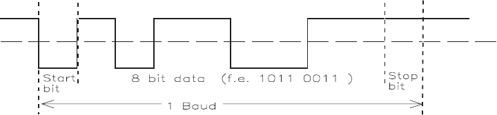
The P-Bus interface configuration is initially set at:
- 1 Start bit
- 8 Data bit
- 1 Stop bit
- 9600 Baud rate
- No Parity
The signal levels must be equal to the RS232 specifications.
The signal lines are only “Transmit Data” and “Receive Data”. Bi-directional lines are not used.
The projector can be controlled by other control signals beside the P-Bus Interface. Details can be found in a
special marketing publication.
The P-Bus is also used as Service Interface for the Diagnostic Software.
figure 3-14
SM 2547-1 Service Manual
Kodak AG, Stuttgart 3-17 03/98
Command Structure
The Command Structure is binary coded with three consecutive 8-bit bytes. Synchronization is achieved by a
break in the transmission of more than three byte times. The first five bit of each command specifies the address
of the selected projector.
The 16 hardware addresses are 0-F (hex).
The address 1F (hex) is a global address that all connected projectors will accept. Several projectors can be
combined in a group by assigning them a special group address of 10 - 19 hex with a software command. Note,
global or group addresses are separate from the position that is selected on the address switch.
Three 8-bit bytes:
AAAAA MM 1 CCCC XXXD XXXXXXXD
1. Byte 2. Byte 3. Byte
AAAAA address of projector
MM selects command mode
CCCC commands depending on selected mode
XXXX XXXX XXX commands or information depending on selected mode
An example of command modes is:
- parameter mode 00
- set/reset mode 01
- direct mode 10
- status request mode 11 In this mode, the projector returns (10 bit) data.
This mode can be used for diagnostics purposes.
Details can be obtained from special marketing literature.
Service Manual SM 2547-1
03/98 3-18 Kodak AG, Stuttgart
Accessory slot
This slot was designed for EKTAPRO Models 7020, 9020 and 9020/CINE to receive certain professional
dissolve
units. The 12/7 PIN ADAPTER is a PCB with:
•an “Intern/Extern” switch for a check. Intern means “Lamp on” and Extern means
“Projector is controlled by the dissolve unit”.
•connectors to connect the ADAPTER to the projector, and an ADAPTER CABLE for
different dissolve units. The ADAPTER CABLE has a 25 PIN SUB-D connector to connect
the PCB ADAPTER and a combination socket for 12 and 7 PINS.
Accessories that allow the EKTAPRO projectors to communicate with older dissolve equipment are available for
the 12/7 PIN sockets.
The slot contains an Inter IC Communication Interface (I2C). The I2C bus is used in a modified way only for the
7/12 PIN Adapter. Typical I2C functions are not available.
a) Possible Control Functions
- P-Bus function in TTL Level through RS_232_R and RS232_T lines
- LAMP dissolve through SL_DISS line
-I
2C Communication through SDA, I2C_INT and SLC lines
- Voltage Supply for accessory slot modules. See 2.4 CONNECTORS.
- Special Control lines SLOT_A, SLOT_B, SLOT_C
All lines are connected to ground means 12/7 PIN adapter present, PROJECTOR LAMP
off, waiting for dissolve pulses on SL_DISS line
- all high, no ACCESSORY installed
SM 2547-1 Service Manual
Kodak AG, Stuttgart 3-19 03/98
Remote Control
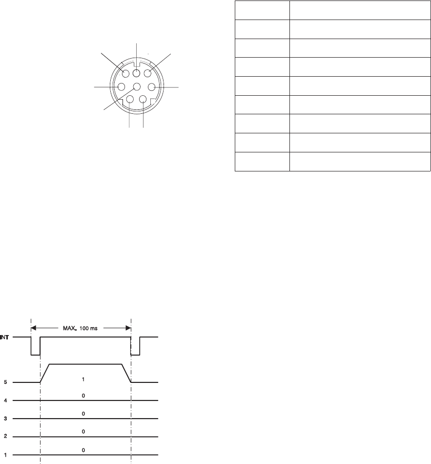
Pin No. Signal
112 VDC
2Gnd
3Signal 1 (LSB)
4Signal 2
5Signal 3
6Signal 4
7Signal 5 (MSB)
8Interrupt
12 VDC = average value between
7.2VDCand14.5VDC
Because of the microprocessor, the REMOTE CONTROL also works with digital signals on the TTL level.
RANDOM ACCESS is also available through a REMOTE CONTROL receptacle.
The data is sent parallel as a 5 bit code from the CABLE REMOTE or the IR RECEIVER to the projector
(Keyboard PCB) with an interrupt signal.
The example shows the binary code
10000.The code 10000 is for FORWARD.
When a button on the REMOTE CONTROL
is pressed, the INT signal is low with a
maximum value of 1 µs. Then it becomes
high again. After that the data transmission
begins.
While the focus and tray motion signal consist of only one 5 bit data record. The slide position values are always
sent as three successive 5 bit data.
For example:
Slide No. 3 = decimal 20 20 23 , binary 10100 10100 10111
Slide No. 140 = decimal 21 24 20 , binary 10101 11000 10100
figure 3-15
5
1
2
3
4
6
7
8
Type Mini DIN
(
viewed from front
)
figure 3-16
Service Manual SM 2547-1
03/98 3-20 Kodak AG, Stuttgart

List of Remote Control Commands:
Key/Function Command decimal Command binary
54321
Slide forward 16 10000
Slide backwards 8 01000
Focus forward 4 00100
Focus backwards 2 00010
Standby 1 00001
Key 1 21 10101
Key 2 22 10110
Key 3 23 10111
Key 4 24 11000
Key 5 25 11001
Key 6 26 11010
Key 7 27 11011
Key 8 28 11100
Key 9 29 11101
Key 0 20 10100
Clear Internal
Enter 3 words internal
SM 2547-1 Service Manual
Kodak AG, Stuttgart 3-21 03/98
blank page
Service Manual SM 2547-1
03/98 3-22 Kodak AG, Stuttgart
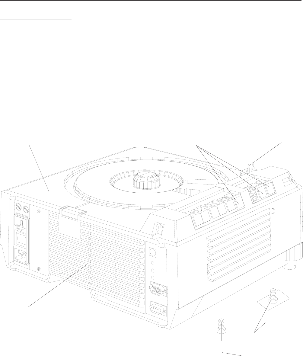
4. DISASSEMBLY/ASSEMBLY
UPPER HOUSING
1. Remove the LAMP MODULE.
2. Remove the KNOB.
3. Remove the 4 SCREWS.
4. Remove the UPPER HOUSING.
UPPER HOUSING KNOB
BUTTONS ( 3)
SCREWS (4)
LAMP MODULE LABEL
figure 4-1
SM2547-1 Service Manual
Kodak AG, Stuttgart 4-1 03/98
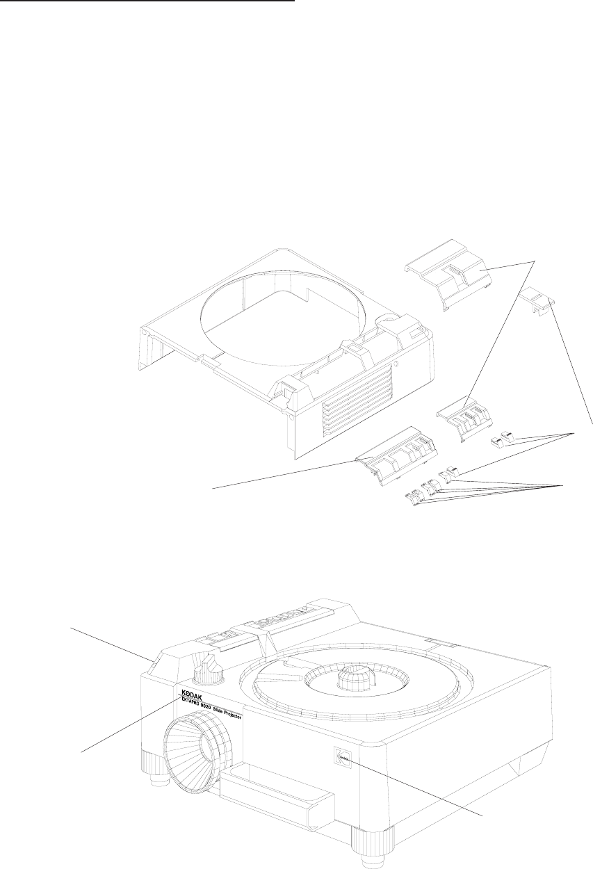
BUTTONS and COVER PLATES
1. Remove the UPPER HOUSING. See page 4-1.
2. Remove the 3 BUTTONS.
3. Remove the small COVER PLATE.
4. Loosen the HOLDING CLIP and remove the large COVER PLATE.
5. If needed, change the 5 BUTTONS.
6. If necessary, replace the WINDOW and/or MODEL LABEL.
Model 9020
CORPORATE SYMBOL
WINDOW
MODEL LABEL
figure 4-2
BUTTONS (5)
BUTTONS (3)
small COVER PLATE
large COVER PLATE
figure 4-3
Service Manual SM2547-1
03/98 4-2 Kodak AG, Stuttgart
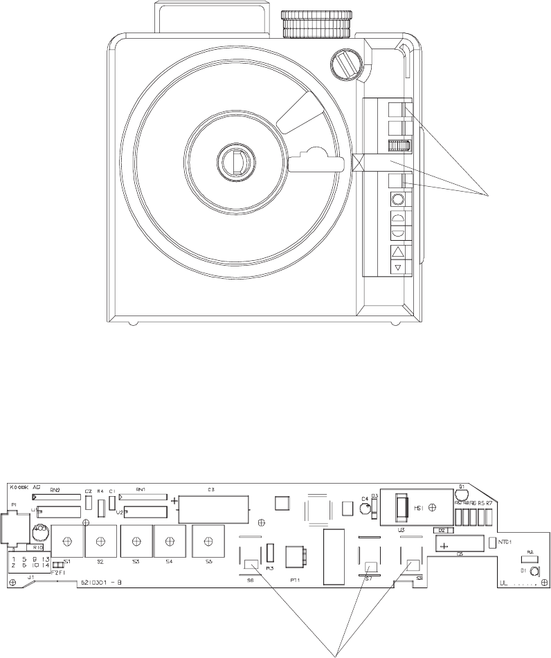
Assembly
NOTE
Please note the positions of the 3 BUTTONS and the SWITCH on the KEYBOARD PCB.
BUTTONS (3)
figure 4-4
SWITCH POSITION on the KEYBOARD PCB
figure 4-5
SM2547-1 Service Manual
Kodak AG, Stuttgart 4-3 03/98
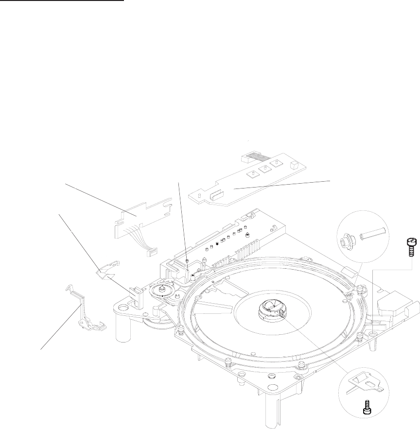
CENTER HOUSING
1. Remove the UPPER HOUSING. See page 4-1.
2. Remove the FOCUS INDICATOR.
3. Release the HOLDING CLIP at the KEYBOARD and remove the PCB.
4. Release the HOLDING CLIP at the TRAY MOTION PCB and remove the PCB.
5. Remove the SPRING and the ZERO LEVER. See figure 4-7.
6. Remove the 8 RETAINERS and 8 ROLLERS. See figure 4-7.
7. Remove the DRIVE RING. See figure 4-7.
8. Remove the 3 SHAFT ROLLERS and the 3 BEARING ROLLERS. See figure 4-7.
KEYBOARD PCB
KEYBOARD
HOLDING CLIP
FOCUS
INDICATOR
TRAY
MOTION
PCB+
HOLDING
CLIP
figure 4-6
Service Manual SM2547-1
03/98 4-4 Kodak AG, Stuttgart
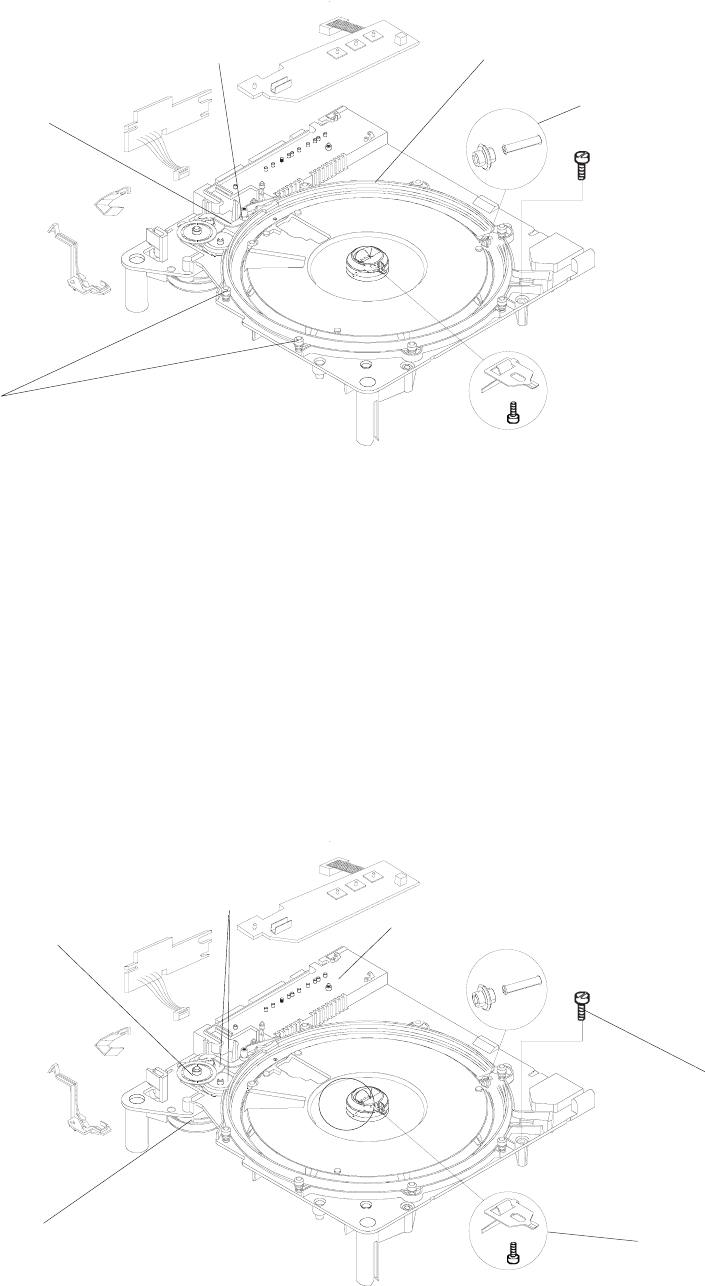
9. Remove the CODER DISK and 2 GEAR WHEELS.
10. Remove the 4 SCREWS.
11. Remove the CENTER HOUSING.
12. Remove the 2 SCREWS and the MOTOR.
13. Remove the SCREW and the LATCH
DRIVE RING
SHAFT ROLLERS (3)
BEARING ROLLERS (3)
RETAINERS (8)
ROLLERS (8)
ZERO
LEVER
SPRING
figure 4-7
CODER DISK
GEAR
WHEELS
(2)
SCREWS (4)
LATCH/SCREW
MOTOR
SCREWS (2)
CENTER HOUSING
figure 4-8
SM2547-1 Service Manual
Kodak AG, Stuttgart 4-5 03/98
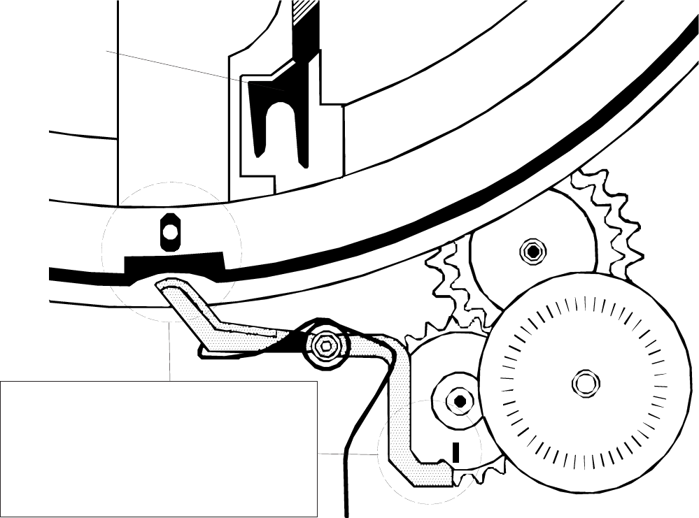
14. During disassembly and assembly of the CENTER HOUSING, place the TRAY RELEASE LEVER into
the position as shown below.
TRANSPORT
RELEASE LEVER
IMPORTANT:
Take care of this positions! Incorrect positioning
can cause transport failures.
figure 4-9
Service Manual SM2547-1
03/98 4-6 Kodak AG, Stuttgart
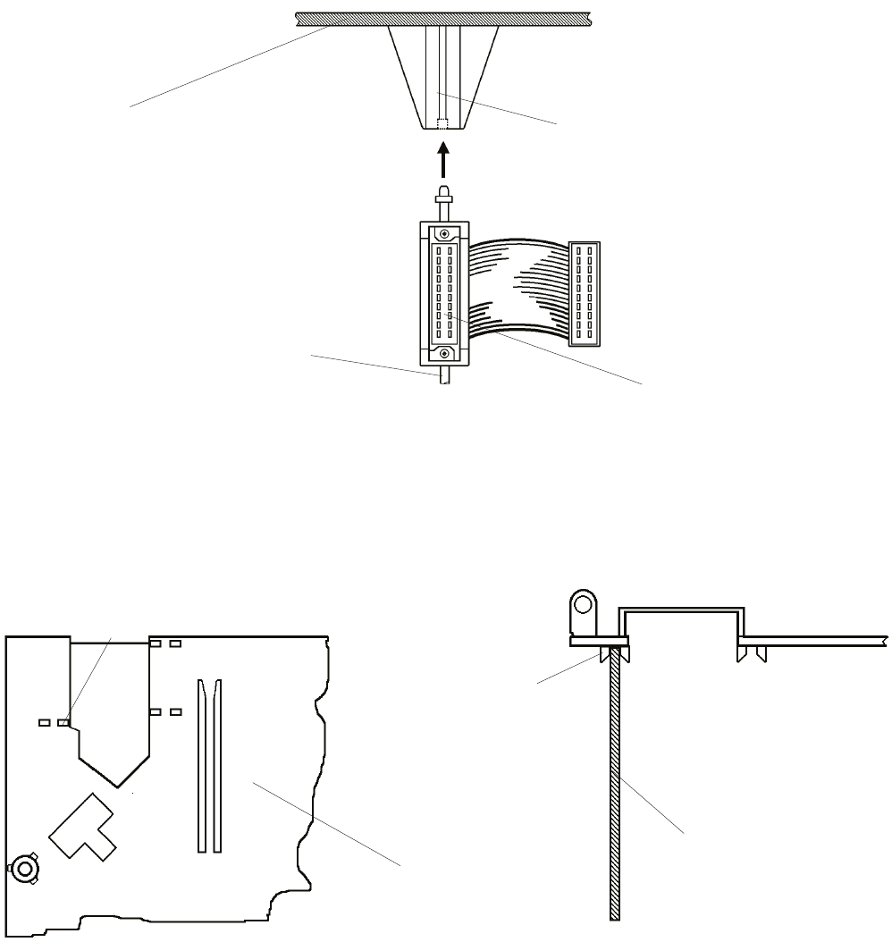
15. At the accessory slot, insert the ADAPTER into the GUIDE of the CENTER HOUSING.
16. Check that the POWER SUPPLY PCB is positioned in the GUIDE of the CENTER HOUSING.
SOCKET
ADAPTER
CENTER
HOUSING GUIDE
figure 4-10
GUIDE of CENTER
HOUSING
POWER SUPPLY PCB
CENTER
HOUSING
GUIDE of CENTER
HOUSING
figure 4-11
SM2547-1 Service Manual
Kodak AG, Stuttgart 4-7 03/98
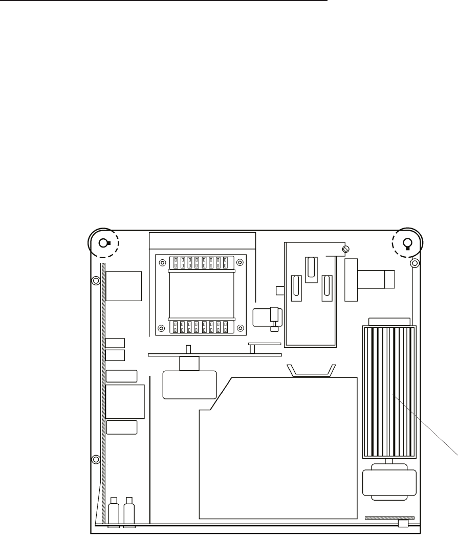
FAN, KEYBOARD PCB and TRAY MOTION PCB
1. Remove the UPPER HOUSING. See page 4-1.
2. Remove the CENTER HOUSING. See page 4-4.
3. Disconnect the FAN MOTORS.
4. Remove the FAN.
5. Disconnect the KEYBOARD PCB.
6. Disconnect the TRAY MOTION PCB.
NOTE:
Do not clean the FAN with compressed air because the rotary wings would be demaged!
FAN
figure 4-12
Service Manual SM2547-1
03/98 4-8 Kodak AG, Stuttgart
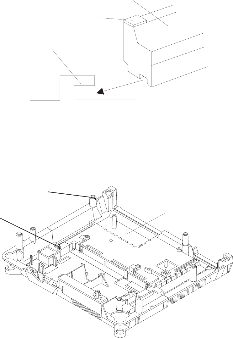
NOTE
When placing the FAN in the LOWER HOUSING, insert the FAN as shown in figure 4-13.
FAN
GUIDE
LOWER HOUSING
FOAM
figure 4-13
GUIDE for
FAN
GUIDE HOLE for FAN
LOWER HOUSING
figure 4-14
SM2547-1 Service Manual
Kodak AG, Stuttgart 4-9 03/98
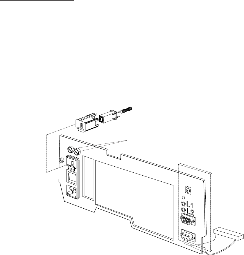
BACK PANEL PCB
1. Remove the UPPER HOUSING. See page 4-1.
2. Remove the CENTER HOUSING. See page 4-4.
3. Remove the FAN. See page 4-9.
4. Remove the BACK PANEL PCB.
FUSE HOLDER
ASSEMBLY
figure 4-15
Service Manual SM2547-1
03/98 4-10 Kodak AG, Stuttgart
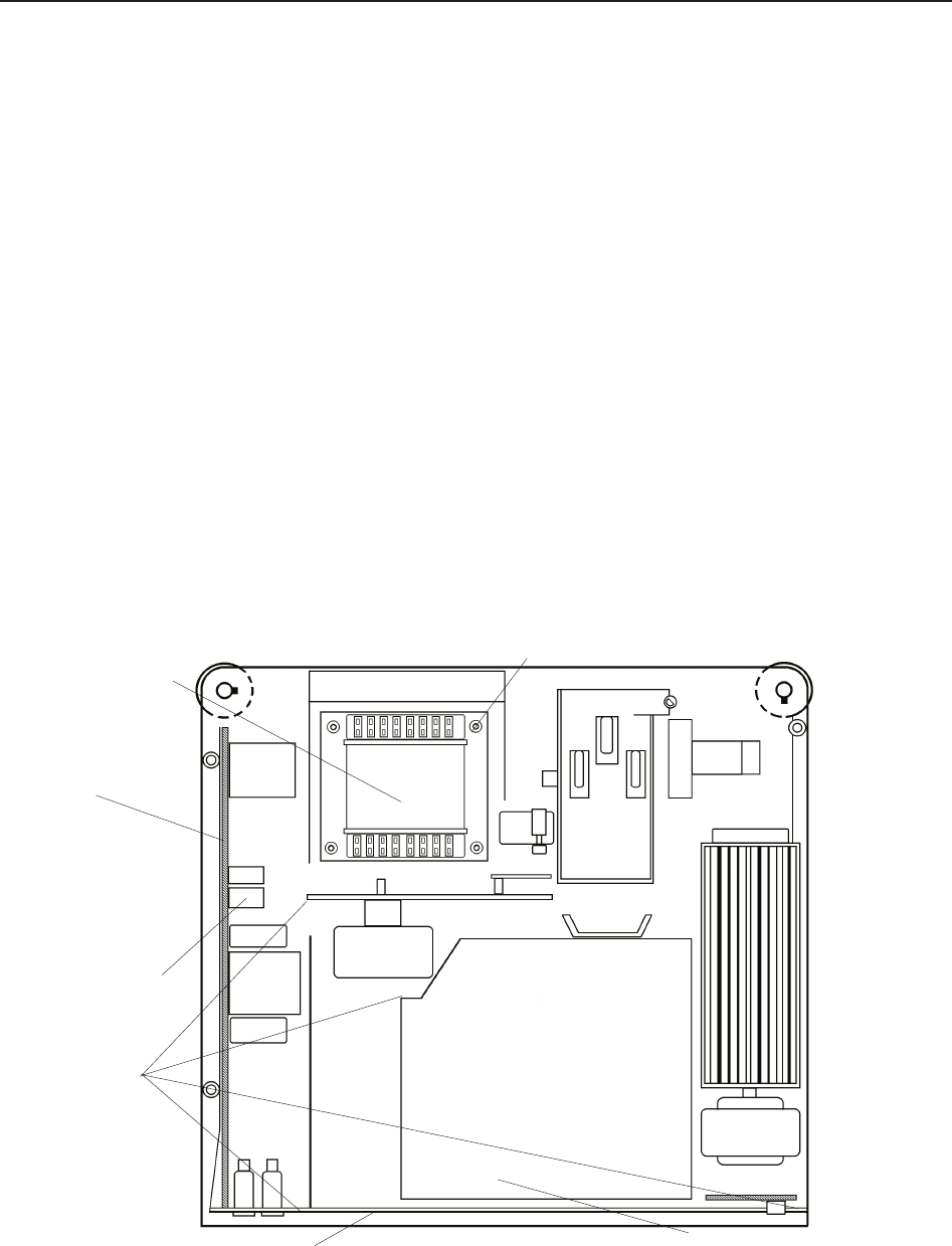
TRANSFORMER, POWER SUPPLY PCB and BACK PLATE ASSEMBLY
NOTE
It is easier to remove the complete TRANSFORMER, POWER SUPPLY PCB and BACK PANEL ASSEMBLY
at the same time, to avoid needless removals.
1. Remove the UPPER HOUSING. See page 4-1.
2. Remove the CENTER HOUSING. See page 4-4.
3. Remove the 4 SCREWS from the TRANSFORMER
4. Remove the CONNECTOR P3 from the POWER SUPPLY PCB.
5. Remove the NEUTRAL WIRE at the MECHANISM FRAME and the LAMP HOUSING ASSEMBLY.
6. Disconnect POWER SUPPLY PCB from the MASTER BOARD PCB. Remove the TRANSFORMER and
the BACK PLATE ASSEMBLY.
7. If needed, install new assemblies.
LAMP HOUSING ASSEMBLY
BACK PLATE ASSEMBLY
NEUTRAL
WIRES
CONNECTORS(P3)
POWER
SUPPLY
PCB
TRANSFORMER
SCREW (4)
figure 4-16
SM2547-1 Service Manual
Kodak AG, Stuttgart 4-11 03/98
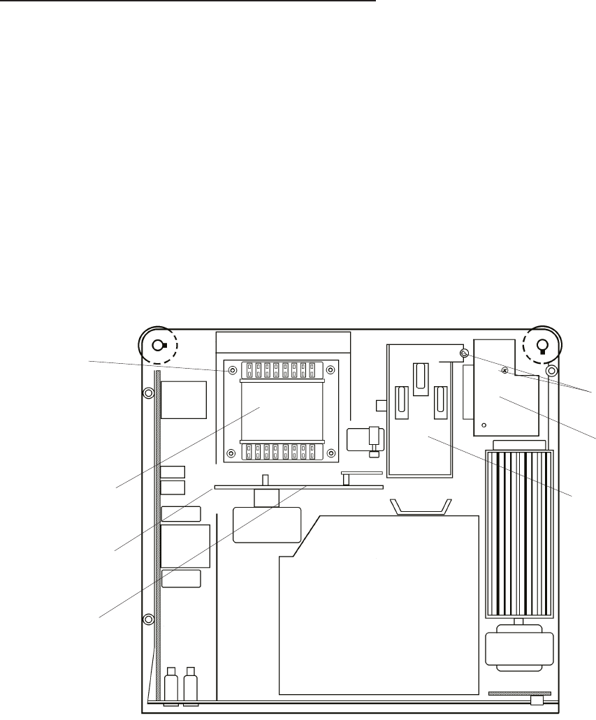
MECHANISM FRAME and LENS MOUNT
1. Remove the UPPER HOUSING. See page 4-1.
2. Remove the CENTER HOUSING. See page 4-4.
3. Remove the 4 SCREWS and the TRANSFORMER. See page 4-11.
4. Remove the SCREW and disconnect the NEUTRAL WIRE.
5. For Model 5020, 9020 and 9020/CINE remove the SCREW, the AF PCB and the 2 CONNECTORS from
the AF PCB.
6. Lift the MECHANISM FRAME and LENS MOUNT and remove the 3 CONNECTORS J 3, J 10, J 12.
See page 4-19.
SCREW
LENS MOUNT
MECHANISM
FRAME
SCREW (4)
TRANSFORMER
NEUTRAL WIRE
AF PCB
figure 4-17
Service Manual SM2547-1
03/98 4-12 Kodak AG, Stuttgart
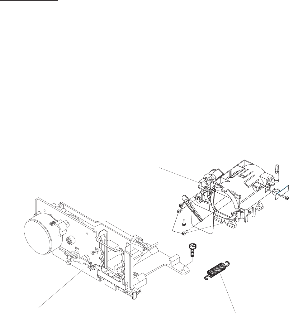
LENS MOUNT
1. Remove the UPPER HOUSING. See page 4-1.
2. Remove the CENTER HOUSING. See page 4-4.
3. Remove the 4 SCREWS and the TRANSFORMER. See page 4-11.
4. Remove the MECHANISM FRAME and LENS MOUNT. See page 4-12.
5. Remove the SPRING.
6. Remove the LENS MOUNT from the MECHANISM FRAME.
LENS MOUNT
SPRING
MECHANISM FRAME
SCREW (3)
figure 4-18
SM2547-1 Service Manual
Kodak AG, Stuttgart 4-13 03/98
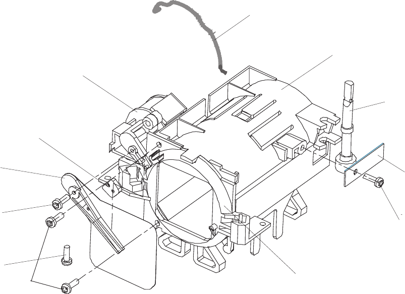
7. Remove the SCREW, PLATE and the SHAFT.
8. Remove the SCREW, SHUTTER and the SHOCK ABSORBER.
9. Remove the SCREW and the MAGNET.
10. Remove the 3 SCREWS, the AUTO FOCUS RETAINER and the SPRING.
SPRING
LENS MOUNT
SHAFT
PLATE
SCREW
SCREW
SCREW (3)
SCREW
SHUTTER
SHOCK
ABSORBER
MAGNET
RETAINER AF ASSEMBLY
figure 4-19
Service Manual SM2547-1
03/98 4-14 Kodak AG, Stuttgart
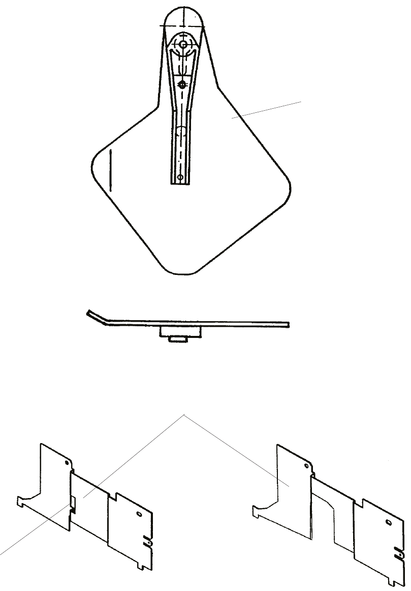
If the SHUTTER has to be replaced and the COVER MECHANISM FRAME is provided with the small recess,
the SHUTTER has to be bent first. Otherwise it might touch the COVER MECHANISM FRAME.
SHUTTER
COVER MECHANISM FRAME
GROOVE
figure 4-20
SM2547-1 Service Manual
Kodak AG, Stuttgart 4-15 03/98
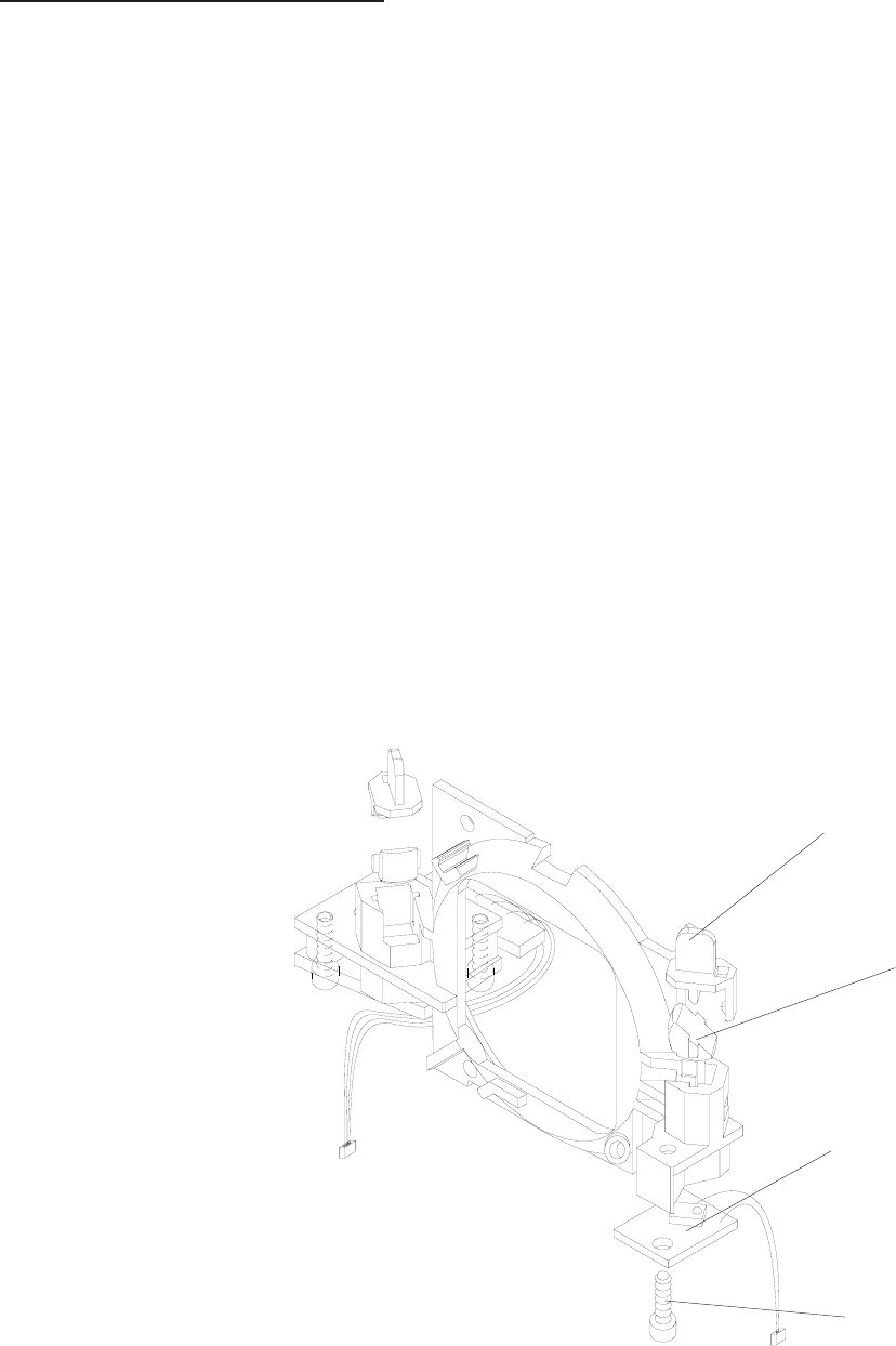
RETAINER AF ASSEMBLY
Model 5020, 9020 and 9020/CINE
1. Remove the UPPER HOUSING. See page 4-1.
2. Remove the CENTER HOUSING. See page 4-4.
3. Remove the 4 SCREWS and the TRANSFORMER. See page 4-11.
4. Remove the MECHANISM FRAME and LENS MOUNT. See page 4-12.
5. Remove the SPRING and the LENS MOUNT from the MECHANISM FRAME. See page 4-13.
6. Remove the SCREW, SHUTTER and the SHOCK ABSORBER. See page 4-14.
7. Rotate the LEVER for the SHUTTER out at the MAGNET.
8. Remove the 3 SCREWS, the RETAINER AF ASSEMBLY, and the SPRING. See page 4-14.
9. Remove the 2 PRISM COVER and the 2 PRISMS.
PRISM COVER (2)
PRISM (2)
TRANSMITTER PCB
SCREW (3)
figure 4-21
Service Manual SM2547-1
03/98 4-16 Kodak AG, Stuttgart
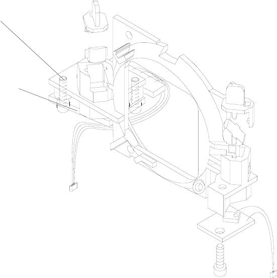
10. Remove the SCREW, the TRANSMITTER PCB, and the TRANSMITTER COVER.
11. Remove the 2 SCREWS and the RECEIVER PCB.
SCREW (3)
RECEIVER PCB
figure 4-22
SM2547-1 Service Manual
Kodak AG, Stuttgart 4-17 03/98
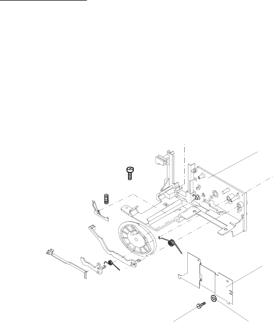
MECHANISM FRAME
1. Remove the UPPER HOUSING. See page 4-1.
2. Remove the CENTER HOUSING. See page 4-4.
3. Remove the 4 SCREWS and the TRANSFORMER. See page 4-11.
4. Remove the MECHANISM FRAME and LENS MOUNT. See page 4-12.
5. Remove the SPRING and LENS MOUNT. See page 4-13.
6. Remove the 2 SCREWS, 2 WASHERS and the COVER MECHANISM FRAME.
MECHANISM
FRAME
MECHANISM
FRAME COVER
WASHER (2)
SCREW (2)
figure 4-23
Service Manual SM2547-1
03/98 4-18 Kodak AG, Stuttgart
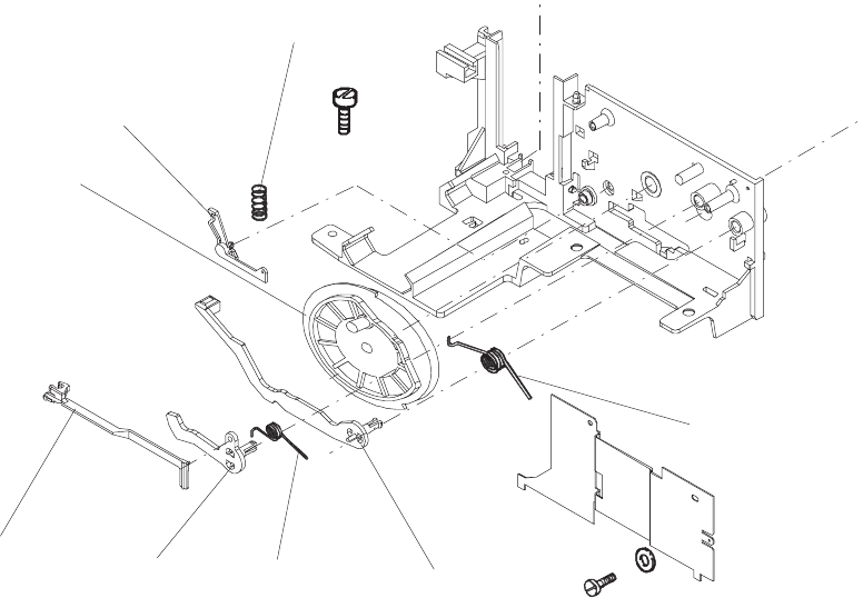
7. Remove the TRAY RELEASE LEVER. See figure 4-24.
8. Remove the LEVER, SLIDE LIFTER and the 2 SPRINGS.
9. Remove the SPRING, SLIDE REGULATION LEVER and the CAM.
NOTE
After the assembly of the parts, align the CAM so that the SLIDE LIFTER is in the lowest position.
SPRING
SLIDE LIFTER
SPRING
LEVER
TRAY RELEASE
LEVER
CAM
SLIDE
REGULATION
LEVER
SPRING
figure 4-24
SM2547-1 Service Manual
Kodak AG, Stuttgart 4-19 03/98
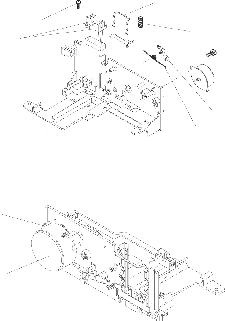
10. Remove the LEVER and the SPRING.
11. Remove the SPRING and the PRESSURE PAD.
12 Remove the 2 SCREWS, the CAM and the SHUTTER SENSOR ASSEMBLY.
13. Remove the 2 SCREWS and the MOTOR.
SCREW (2)
CAM and SHUTTER
SENSOR ASSEMBLY
SPRING
LEVER
SPRING
PRESSURE PAD
figure 4-25
SCREW (2)
MOTOR
figure 4-26
Service Manual SM2547-1
03/98 4-20 Kodak AG, Stuttgart
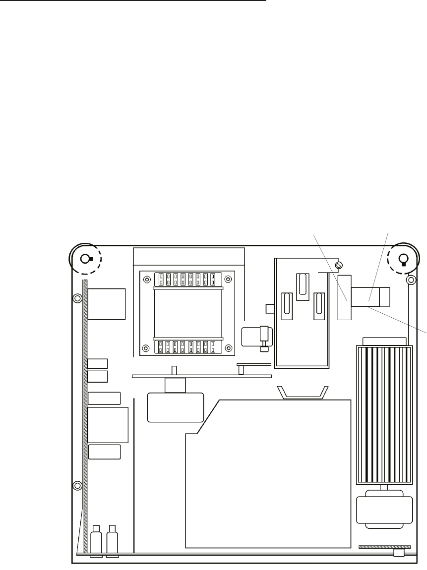
AUTO FOCUS PCB and FOCUS MOTOR
1. Remove the UPPER HOUSING. See page 4-1.
2. Remove the CENTER HOUSING. See page 4-4.
3. Remove the FAN, KEYBOARD PCB, and TRAY MOTION PCB. See page 4-9.
4. Remove the 4 SCREWS and the TRANSFORMER. See page 4-11.
5. Remove the MECHANISM FRAME and LENS MOUNT. See page 4-12.
6. Remove the SPRING, the FOCUS MOTOR and the RUBBER PAD.
SPRING FOCUS MOTOR
RUBBER PAD
figure 4-27
SM2547-1 Service Manual
Kodak AG, Stuttgart 4-21 03/98
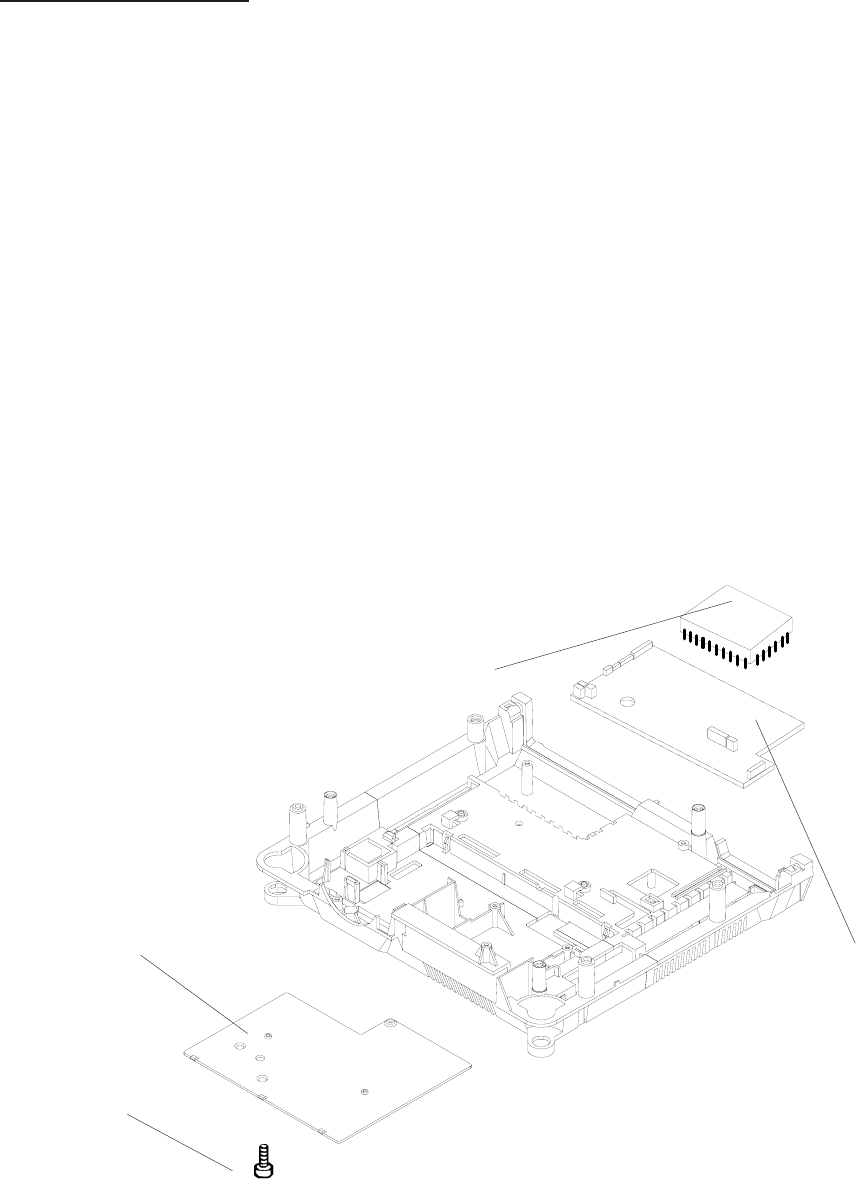
Master Board PCB
1. Remove the UPPER HOUSING. See page 4-1.
2. Remove the CENTER HOUSING. See page 4-4.
3. Remove the FAN, KEYBOARD PCB and the TRAY MOTION PCB. See page 4-9.
4. Remove TRANSFORMER, POWER SUPPLY PCB and BACK PANEL ASSEMBLY. See page 4-11.
5. Remove the MECHANISM FRAME and LENS MOUNT. See page 4-12.
6. Disconnect all CONNECTORS from the MASTER PCB. See page 4-23:
7. Remove the SCREW and the COVER.
8. Remove the MASTER PCB.
SCREW
COVER
MICROCONTROLLER
MASTER BOARD PCB
figure 4-28
Service Manual SM2547-1
03/98 4-22 Kodak AG, Stuttgart
Master Board PCB Connectors
CAUTION
During the assembly take care that all CONNECTORS are correctly plugged in!
MASTERBOARD
Component Side
SMD
J5
J2
J13
J11
J9
J6
J12
P1
J10J3
J4
J1
BACK PANEL PCB MIRROR MOTOR
KEYBOARD PCB ACCESSORY SLOT
AUTO FOCUS PCB CAM and SHUTTER SENSOR
FOCUS MOTOR SLIDE LIFT MOTOR
TRANSPORT MOTOR POWER SUPPLY PCB
SHUTTER SOLENOID
TRAY MOTION PCB
PLCC
PIN-GRID
SOCKET
SM2547-1 Service Manual
Kodak AG, Stuttgart 4-23 03/98
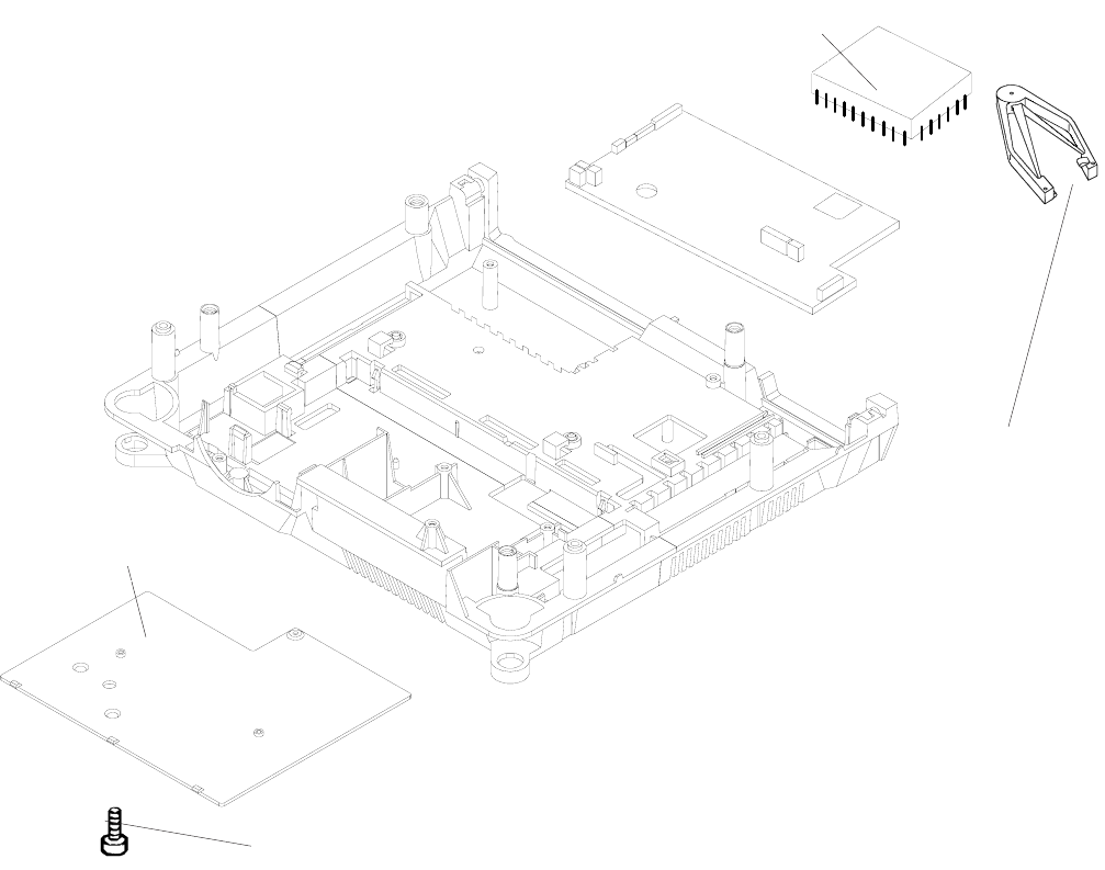
MICROCONTROLLER
1. Remove the UPPER HOUSING. See page 4-1.
2. Remove the CENTER HOUSING. See page 4-4.
3. Remove the SCREW and the COVER.
4. Use a PLCC EXTRACTOR TOOL (TL 4430) to remove the MICROCONTROLLER from the
MASTER PCB.
5. When assembling note the beveled edge of the MICROCONTROLLER and the PLCC/PIN-GRID
SOCKET. Install these edges together.
NOTE
The MICROCONTROLLER is installed in a PLCC-Socket.
MICROCONTROLLER
SCREW
PLCC EXTRACTOR
TOOL (TL 4430)
COVER
Service Manual SM2547-1
03/98 4-24 Kodak AG, Stuttgart
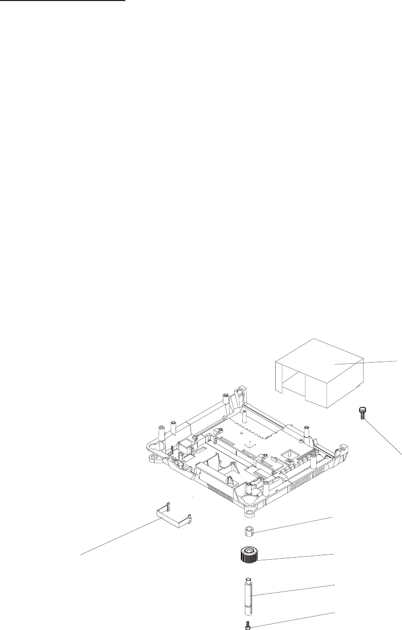
LOWER HOUSING
1. Remove the UPPER HOUSING. See page 4-1.
2. Remove the CENTER HOUSING. See page 4-4.
3. Remove the FAN, KEYBOARD PCB and TRAY MOTION PCB. See page 4-9
4. Remove the TRANSFORMER, POWER SUPPLY PCB and BACK PANEL ASSEMBLY. See page 4-11.
5. Remove the MECHANISM FRAME and LENS MOUNT. See page 4-13.
6. Disconnect all CONNECTORS from MASTER PCB. See page 4-23:
7. Remove the 2 SCREWS and the LAMP HOUSING ASSEMBLY.
8. Remove the HANDLE.
9. Remove the 2 ELEVATOR RETAINERS, the right and left ELEVATOR KNOB, the right and left
ELEVATOR and the 2 RUBBER FEET.
LAMP HOUSING
ASSEMBLY
SCREW (2)
ELEVATOR RETAINER (2)
ELEVATOR KNOB (2)
ELEVATOR (2)
RUBBER FOOT (2)
HANDLE
figure 4-29
SM2547-1 Service Manual
Kodak AG, Stuttgart 4-25 03/98
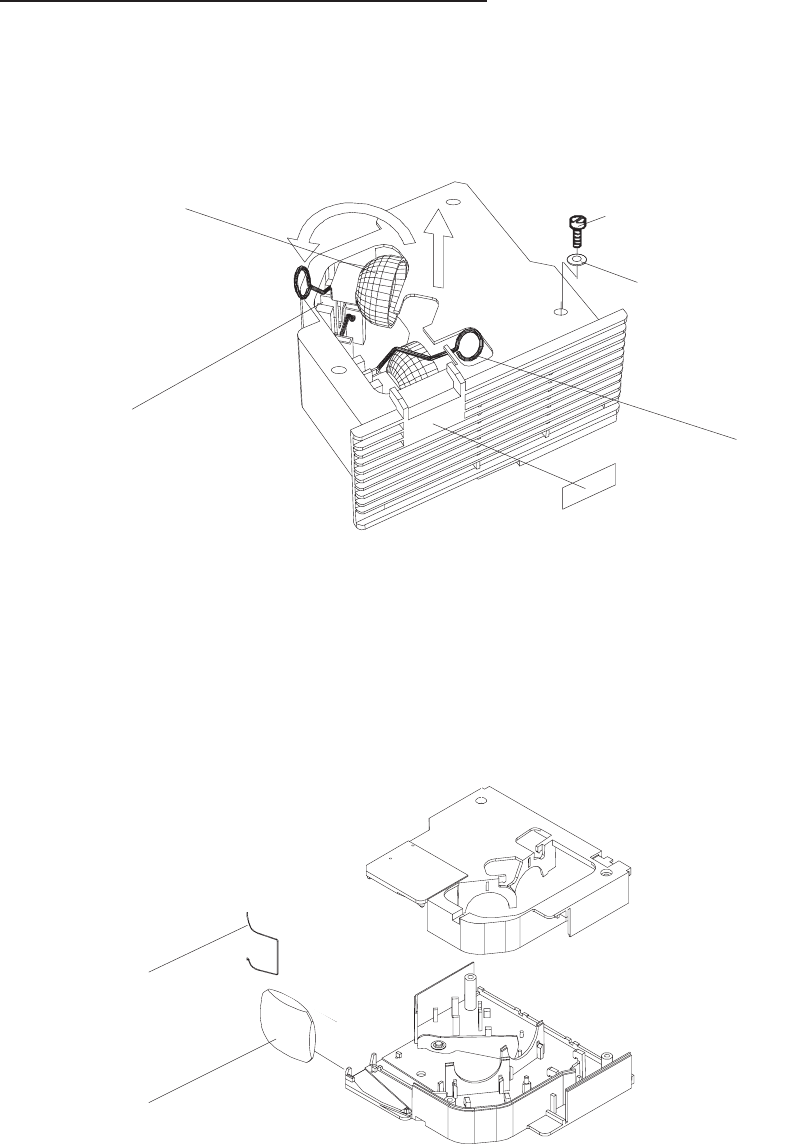
DUAL LAMP MODULE (Extra Bright)
1. Remove the LAMP MODULE from the PROJECTOR.
2. Lift the EJECTOR LEVER . The defective LAMP will eject from the LAMP SOCKET ASSEMBLY.
3. Remove the CLIP and the CONDENSER LENS.
EJECTOR
LAMP SOCKET
ASSEMBLY
LAMP
LABEL
EXTRA BRIGHT
SCREW (3)
WASHER (2)
figure 4-30
CLIP
CONDENSER LENS
figure 4-31
Service Manual SM2547-1
03/98 4-26 Kodak AG, Stuttgart
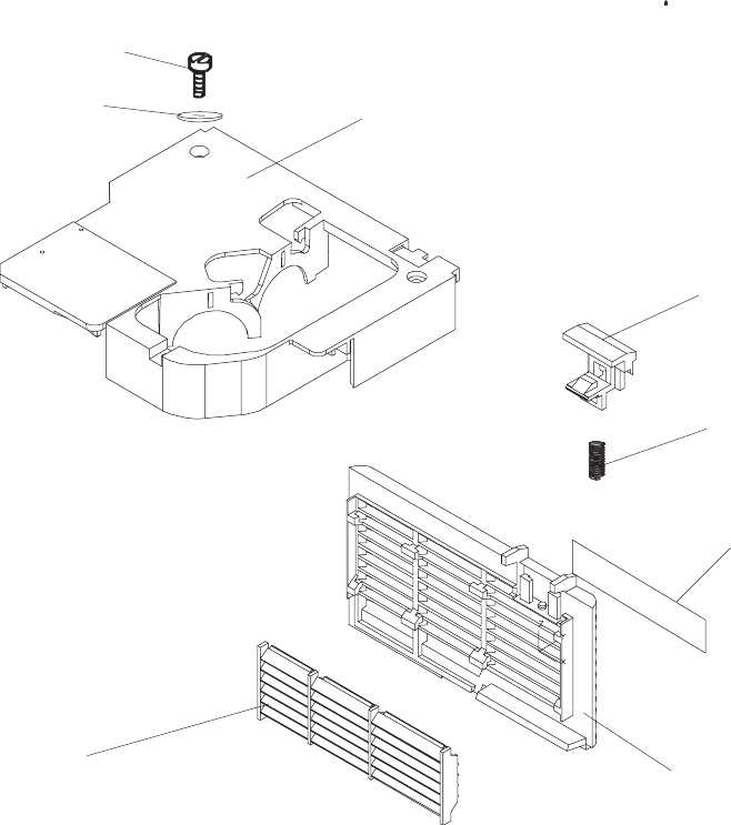
4. Remove the 3 SCREWS, the 2 WASHERS and the LAMP HOUSING.
5. Remove the GRILL PLATE, the AIR EXHAUST PLATE, the HOOK, the SPRING and the LAMP
MODULE LABEL.
LAMP HOUSING
HOOK
SPRING
LAMP MODULE
LABEL
GRILL PLATE
AIR EXHAUST PLATE
SCREW (3)
WASHER (2)
figure 4-32
SM2547-1 Service Manual
Kodak AG, Stuttgart 4-27 03/98
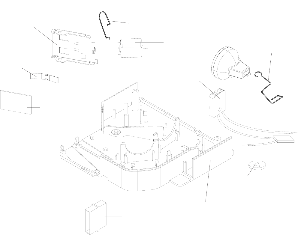
6. Remove the 2 EJECTORS.
7. Remove the SPRING - Model 4020, 5020, 7020 ,9020 and 9020/CINE.
8. Remove the MIRROR, the SPRING and the MIRROR HOLDER.
9. Remove the MOTOR, the CIRCLIP and the SINGLE or DUAL LAMP SOCKET ASSEMBLY from the
PLUG.
MOTOR EJECTOR (2)
SPRING
MIRROR
MIRROR HOLDER
PLUG
LAMP HOUSING
CIRCLIP
SINGLE/DUAL
LAMP SOCKET
ASSEMBLY
SPRING (4020,5020,7020,9020, 9020/CINE)
figure 4-33
Service Manual SM2547-1
03/98 4-28 Kodak AG, Stuttgart
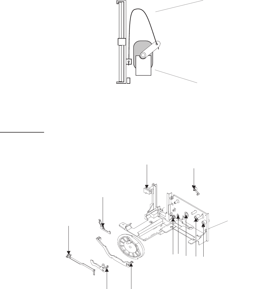
DUAL LAMP MODULE
NOTE
The SPRING in the DUAL LAMP MODULE has to be mounted without tension between the
MIRROR and the MOTOR.
Lubrication
Use the lubricant BARRIERTA L 25 DL (50g) No. 558 1960. Grease all arrow marked spots.
SPRING
MOTOR
figure 4-34
MECHANISM
FRAME
figure 4-35
SM2547-1 Service Manual
Kodak AG, Stuttgart 4-29 03/98
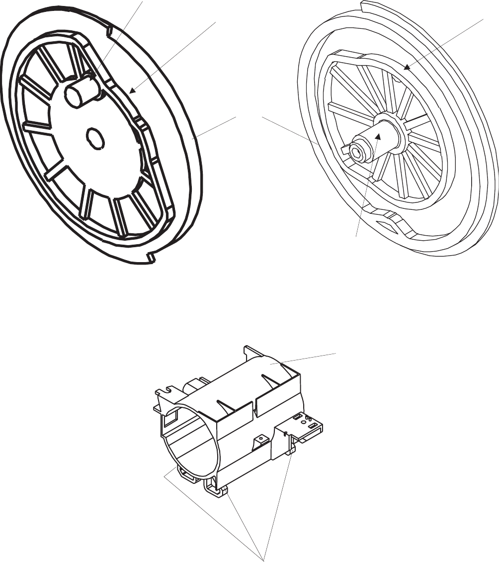
CAM
figure 4-36
GLIDING SURFACE
LENS MOUNT
figure 4-37
Service Manual SM2547-1
03/98 4-30 Kodak AG, Stuttgart
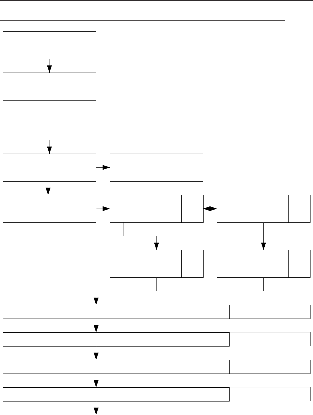
5. DIAGNOSTICS
Diagnostic Overview EKTAPRO 4020/5020/7020/9020 and 9020/CINE
Page
5-3
PREPARATION
Page
5-4
NO FUNCTION
= Power LED
deenergized
= FAN not operating
= LAMP deenergized
Page
5-9
Switch On
Procedure
Problems
Page
5-12
Lamp Problems
4020,5020,7020,
9020, 9020/CINE
Page
5-20
No Funtion with
Remote Control
Page
5-18
Switch On
Procedure
Page
5-19
Switch On Procedure
complete -
No Keyboard Function
Page
5-23
Cable Remote
Page
5-20
IR Remote
No Slide transport forward/reverse Page 5-24
Wrong transport step by 80/140 Slide Tray Page 5-30
No Focus actuation Page 5-32
No Stand-by Function Page 5-34
SM 2547-1 Service Manual
Kodak AG, Stuttgart 5-1 03/98

Communication Trouble 4020 - 9020 and 9020/CINE Page 5-35
Autofocus 5020/9020/9029/CINE : No Autofocus Function Page 5-38
Accessory Slot 7020/9020 Page 5-40
Service Manual SM 2547-1
03/98 5-2 Kodak AG, Stuttgart

Preparation
Conditions:
-
Ensure that line voltage does not vary more than +/- 5 % from the selected value on the
projector.
- Insert a LAMP MODULE with a proper LAMP.
- Slide tray (80/140) with slide
- LENS (standard)
- Personal Computer / Lap top
- Interface Cable 9 PIN (Plug / socket)
SM 2547-1 Service Manual
Kodak AG, Stuttgart 5-3 03/98
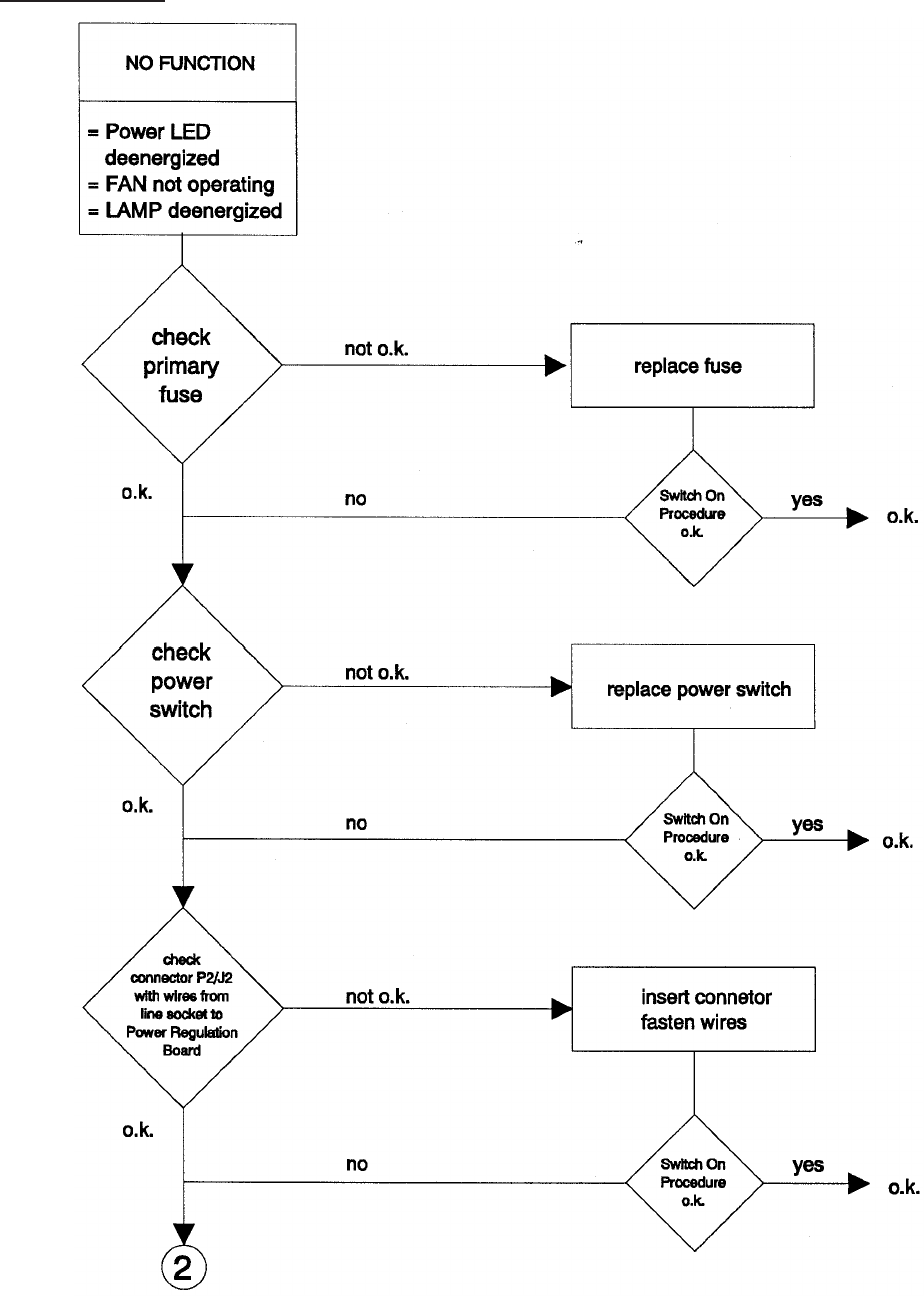
No Function
Service Manual SM 2547-1
03/98 5-4 Kodak AG, Stuttgart
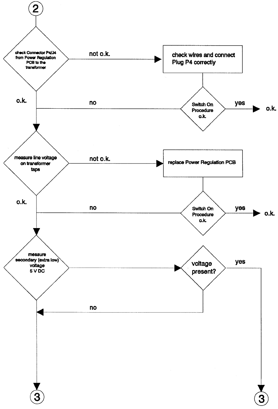
see figure
on page 28
SM 2547-1 Service Manual
Kodak AG, Stuttgart 5-5 03/98
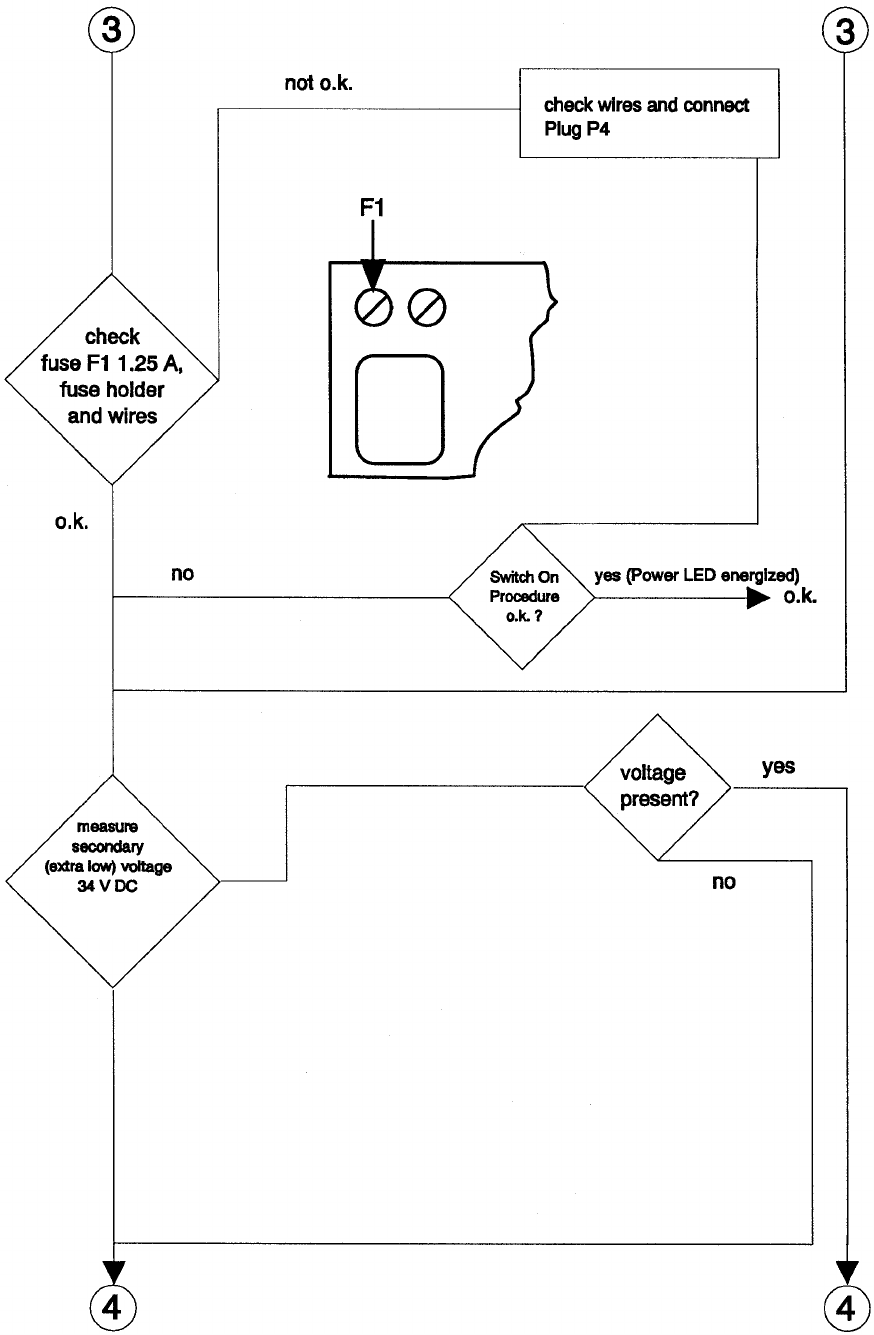
see figure
on page 28
Service Manual SM 2547-1
03/98 5-6 Kodak AG, Stuttgart
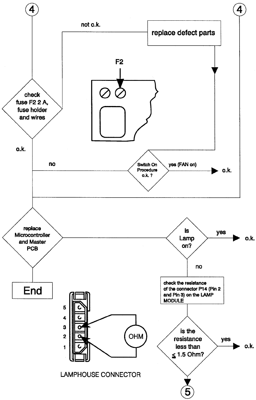
SM 2547-1 Service Manual
Kodak AG, Stuttgart 5-7 03/98
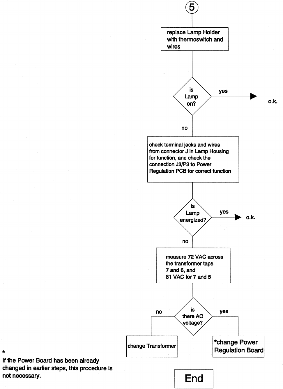
Service Manual SM 2547-1
03/98 5-8 Kodak AG, Stuttgart
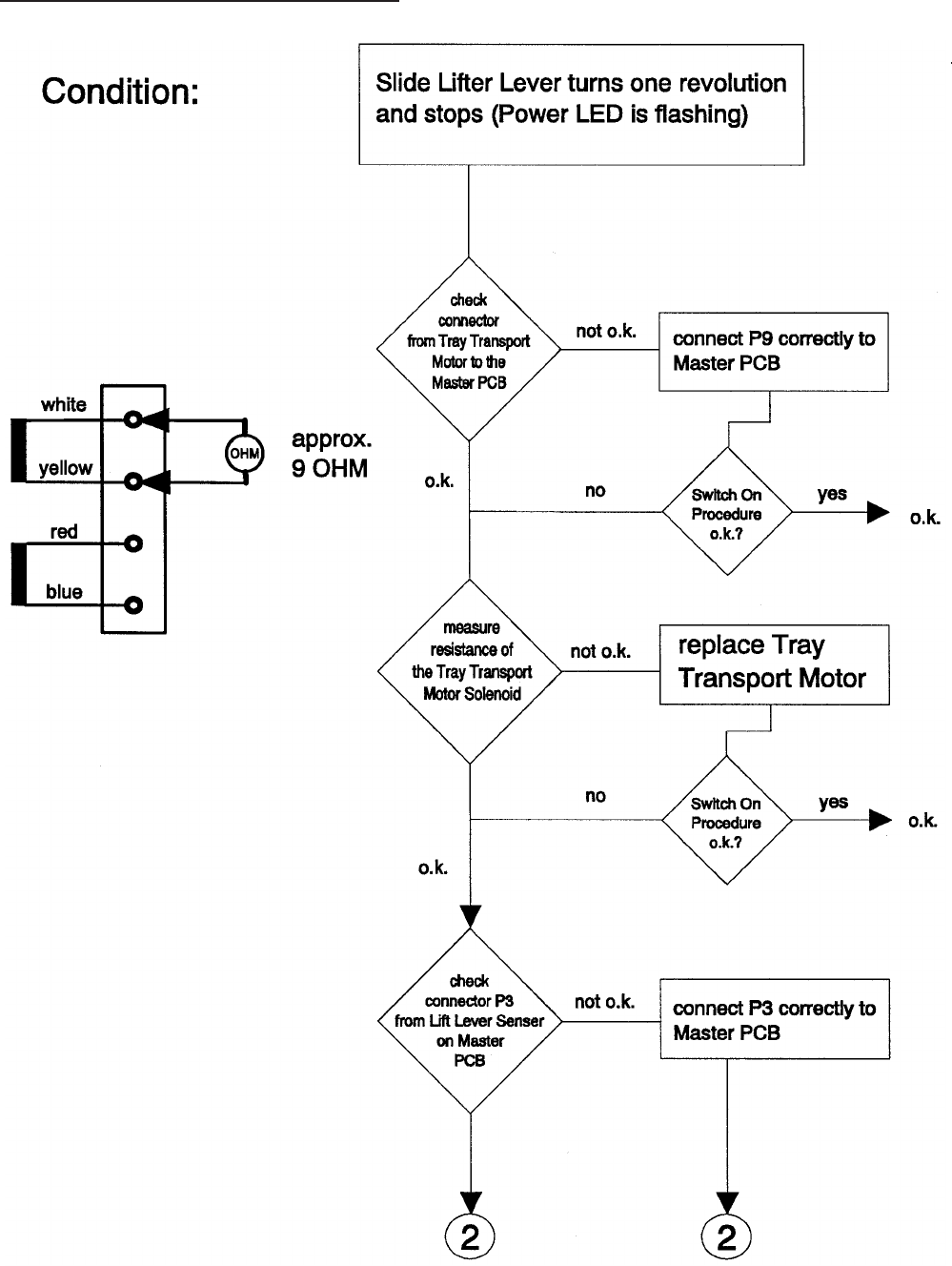
Switch on Procedure Problems
SM 2547-1 Service Manual
Kodak AG, Stuttgart 5-9 03/98
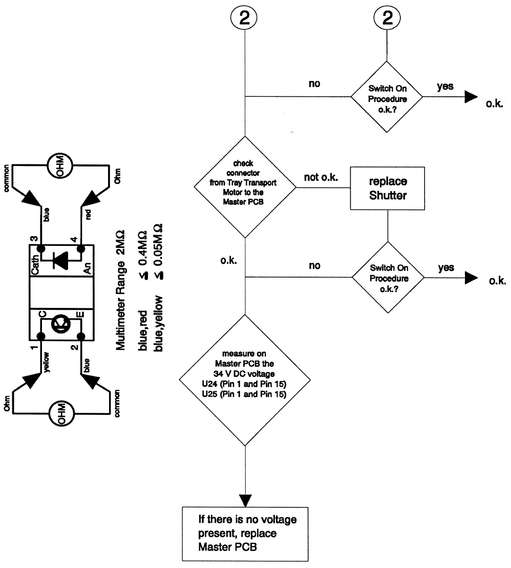
Service Manual SM 2547-1
03/98 5-10 Kodak AG, Stuttgart
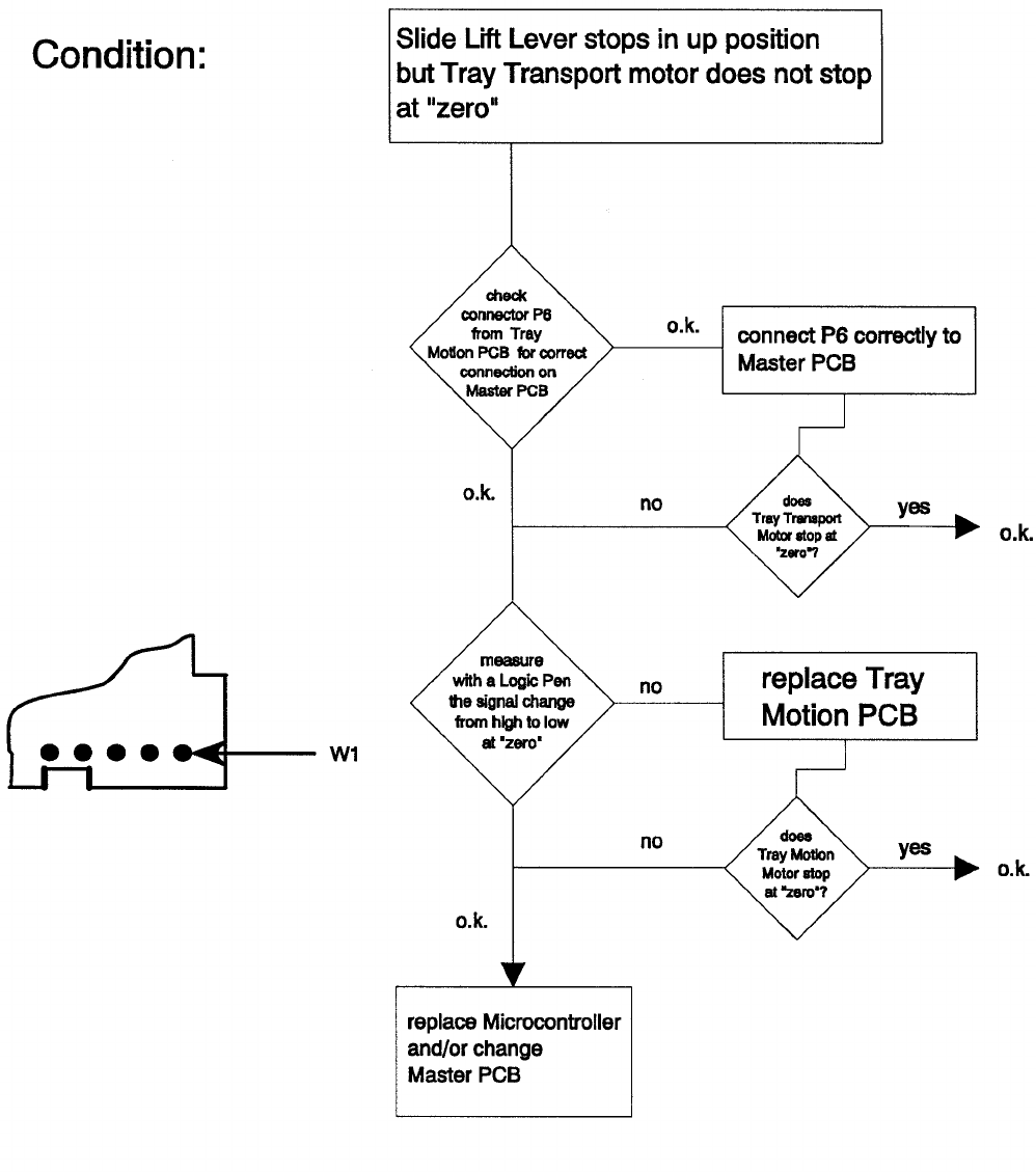
SM 2547-1 Service Manual
Kodak AG, Stuttgart 5-11 03/98
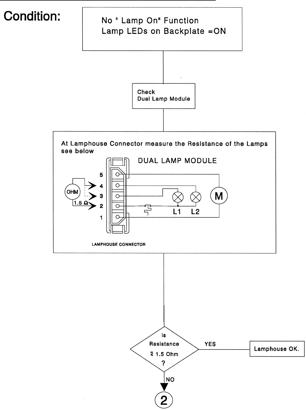
Lamp Problems 4020/5020/7020/9020 and 9020/CINE
Service Manual SM 2547-1
03/98 5-12 Kodak AG, Stuttgart
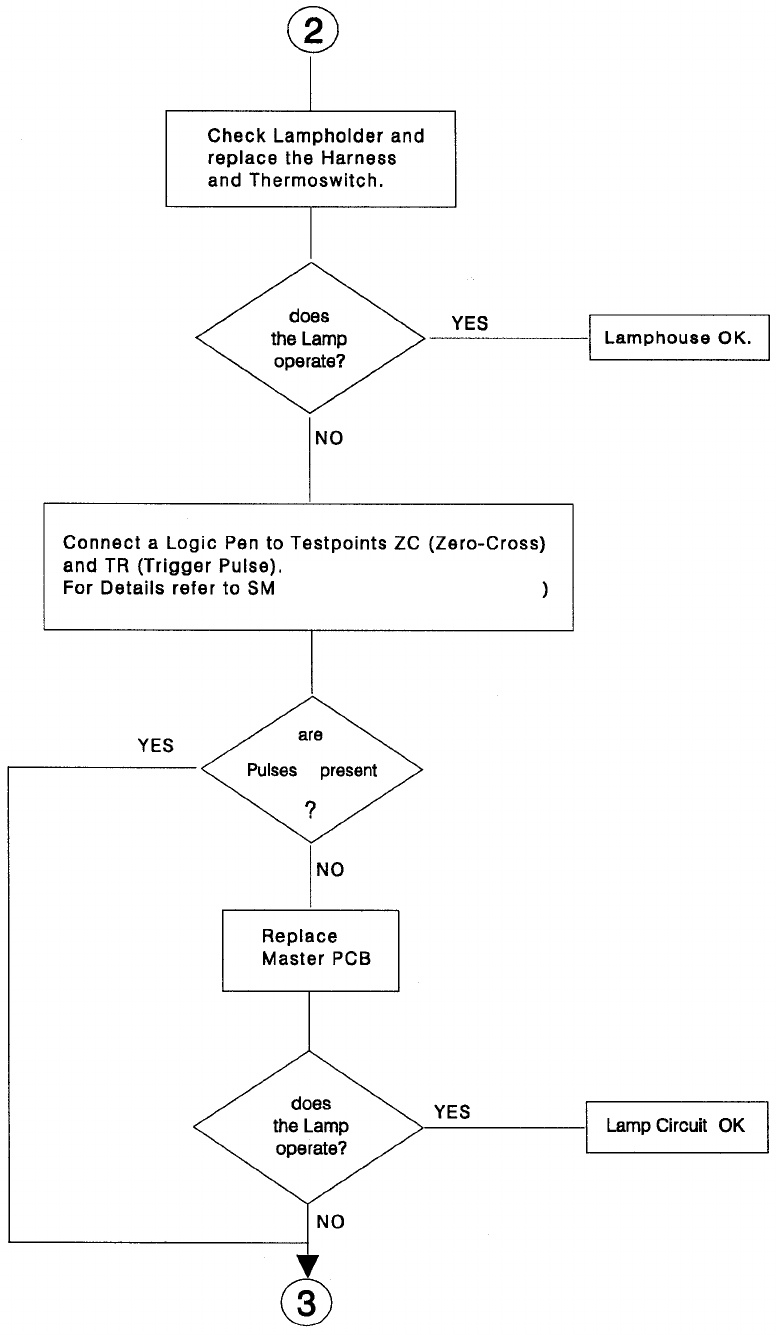
(figure 3-11 and page 5-28)
SM 2547-1 Service Manual
Kodak AG, Stuttgart 5-13 03/98
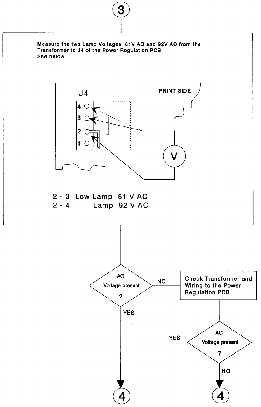
Service Manual SM 2547-1
03/98 5-14 Kodak AG, Stuttgart
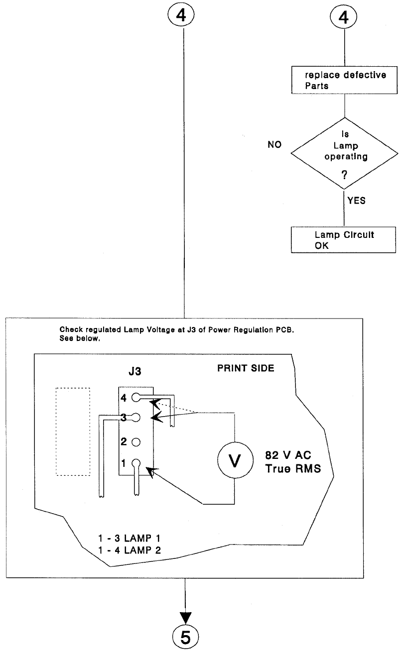
SM 2547-1 Service Manual
Kodak AG, Stuttgart 5-15 03/98
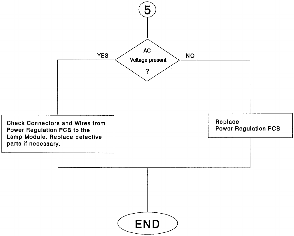
Service Manual SM 2547-1
03/98 5-16 Kodak AG, Stuttgart
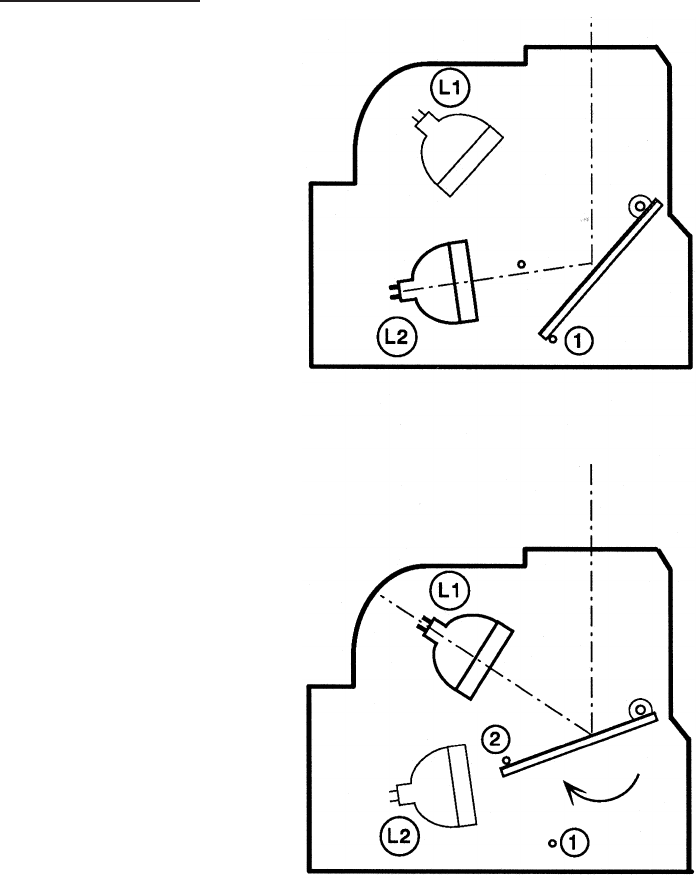
Mirror Position
In the Service Software TL-4575 there is an option in the menu “Lamp toggle” to check the MIRROR FUNCTION
and change the “lamp on” option. For the correct function in the projector, set the MIRROR to position 1 when
Lamp 1 is active, or reset the projector.
If the MIRROR does not move by the software command, check the resistance of the MIRROR DC MOTOR
(see figure) and measure the 34 VDC voltage on the MASTER PCB if necessary.
Brightness Test
Use the option “Adjust Brightness” from the Service Software TL-4575 to dim the PROJECTOR LAMP. There is
a range from “0" (dark) to ”1000" (bright), in steps of 10 units. With the “Reset” command in the main menu the
original brightness can be reset.
SM 2547-1 Service Manual
Kodak AG, Stuttgart 5-17 03/98
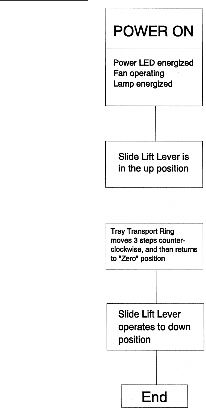
Switch On Procedure
Service Manual SM 2547-1
03/98 5-18 Kodak AG, Stuttgart
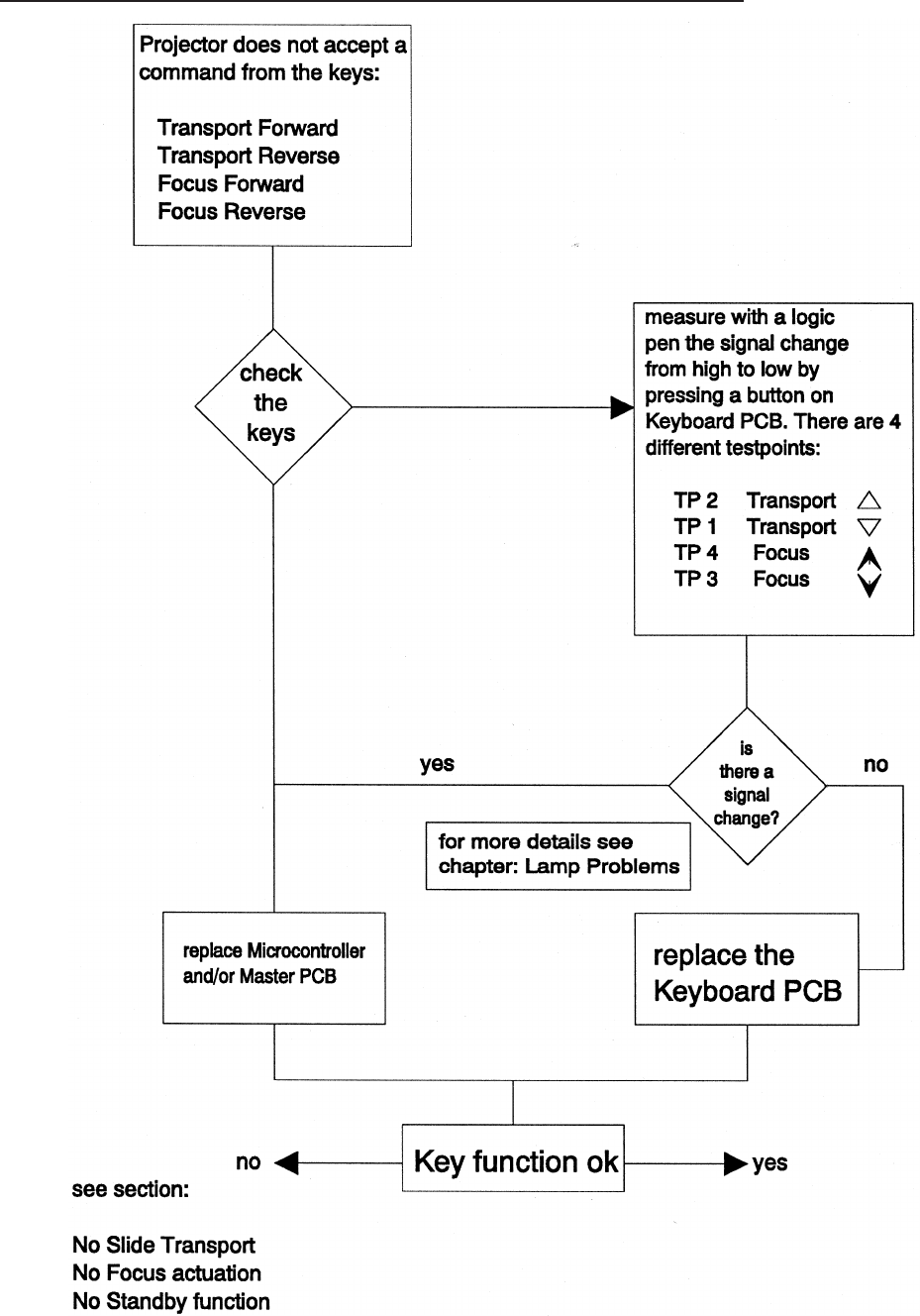
Switch On Procedure complete - No Keyboard Function
SM 2547-1 Service Manual
Kodak AG, Stuttgart 5-19 03/98
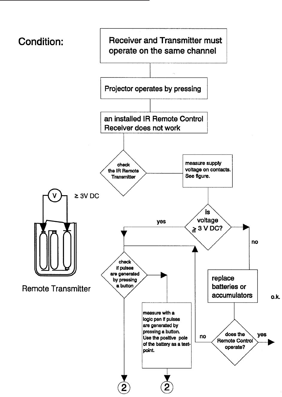
No function with REMOTE CONTROL
IR Remote Control
Service Manual SM 2547-1
03/98 5-20 Kodak AG, Stuttgart
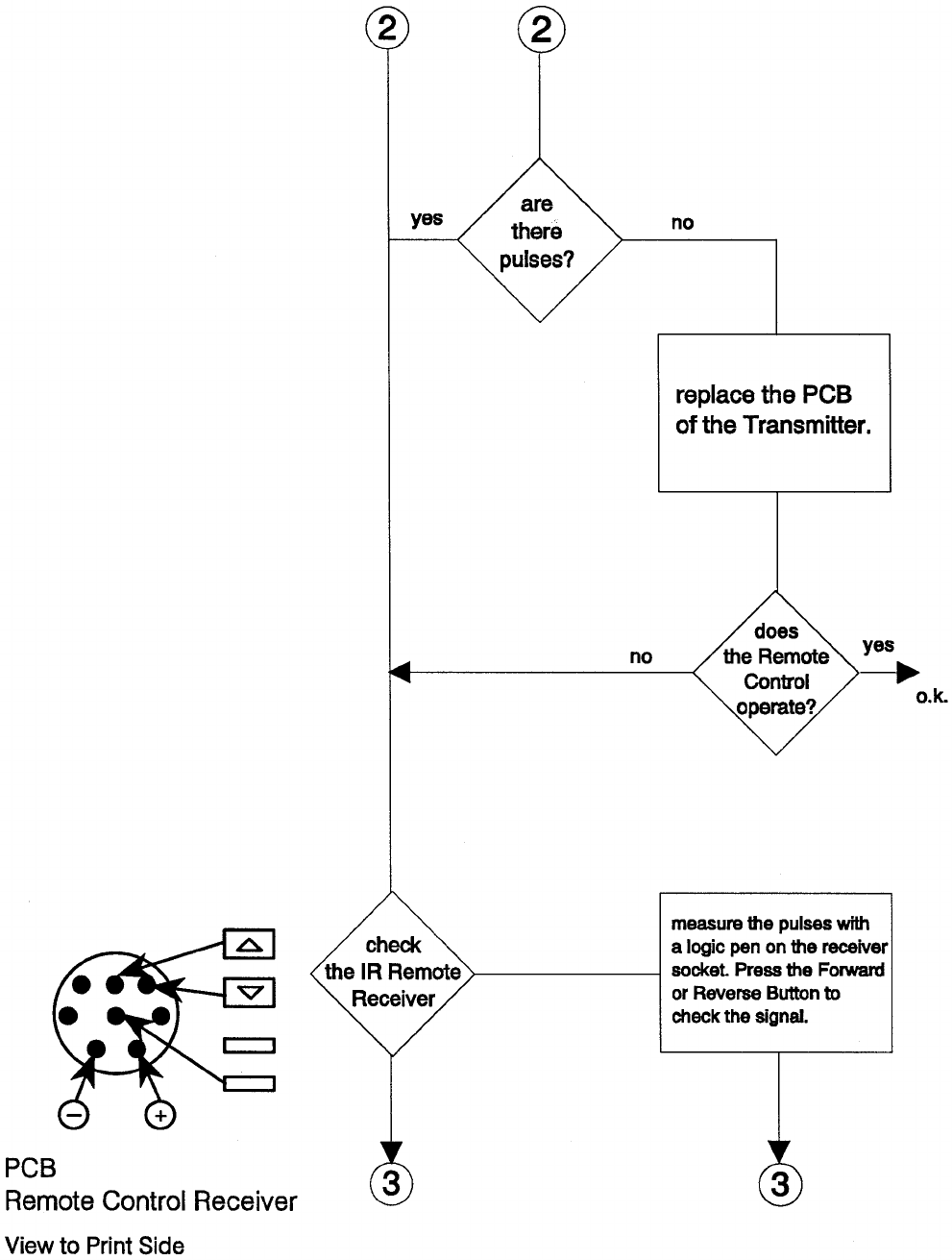
SM 2547-1 Service Manual
Kodak AG, Stuttgart 5-21 03/98
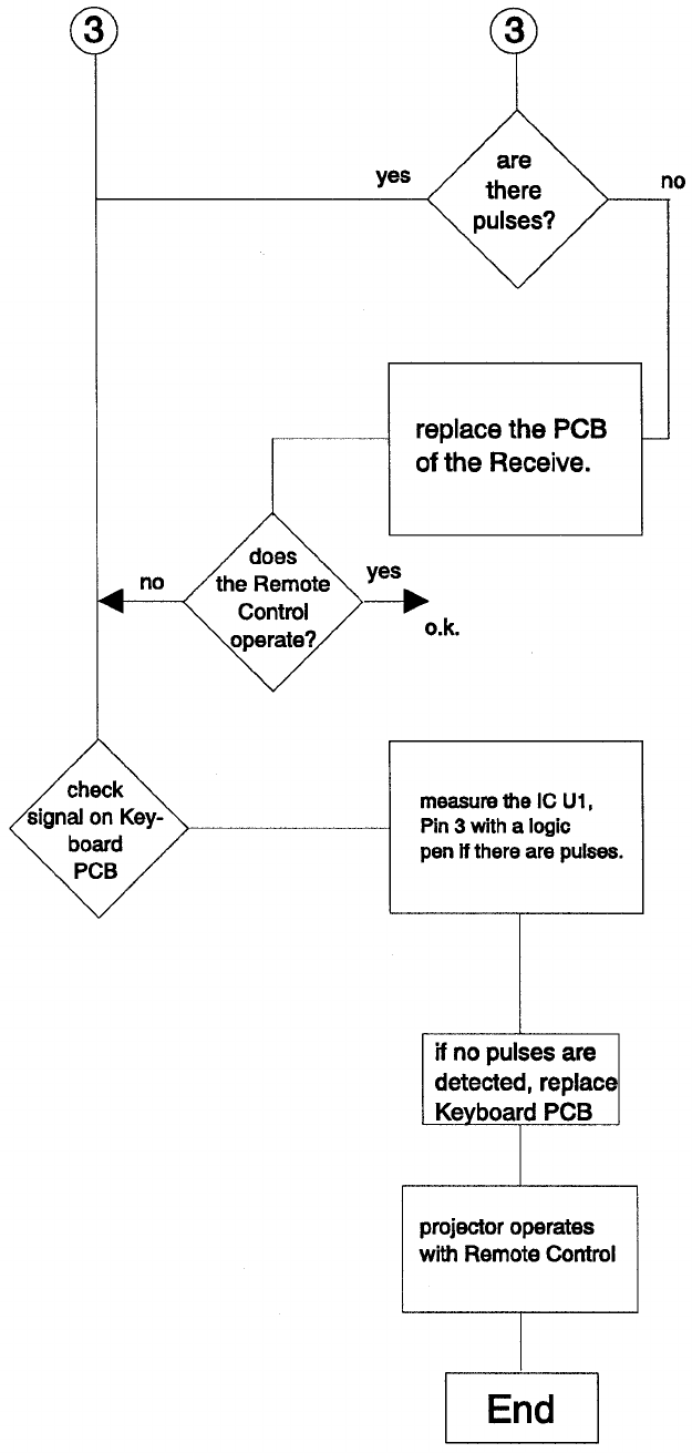
Service Manual SM 2547-1
03/98 5-22 Kodak AG, Stuttgart
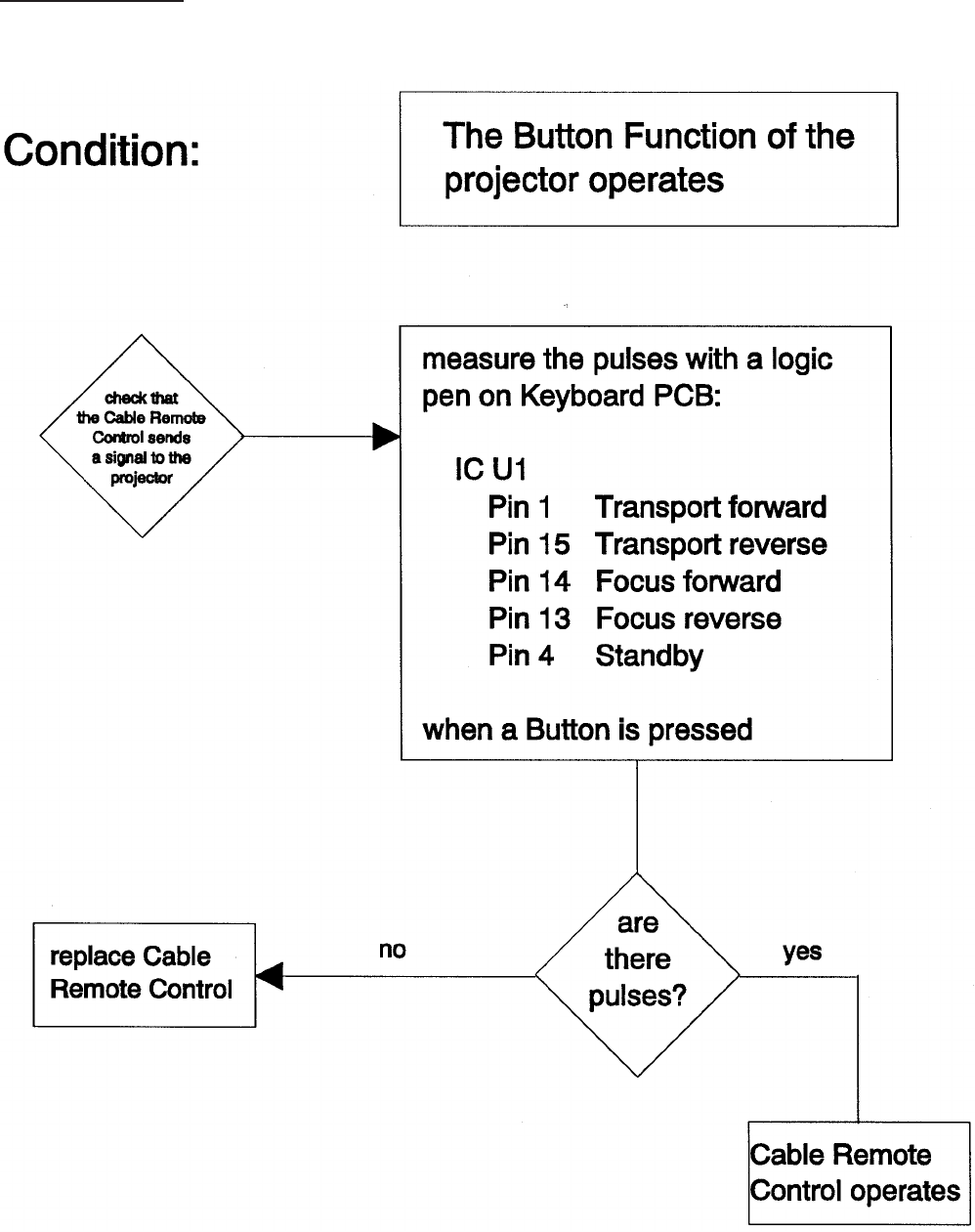
Cable Remote
SM 2547-1 Service Manual
Kodak AG, Stuttgart 5-23 03/98
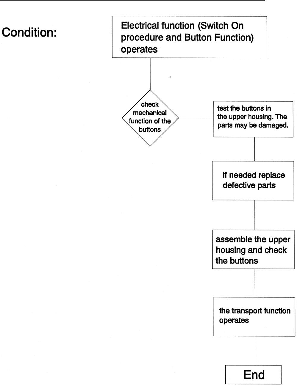
No Slide Transport forward/reverse and other projection problems
Service Manual SM 2547-1
03/98 5-24 Kodak AG, Stuttgart
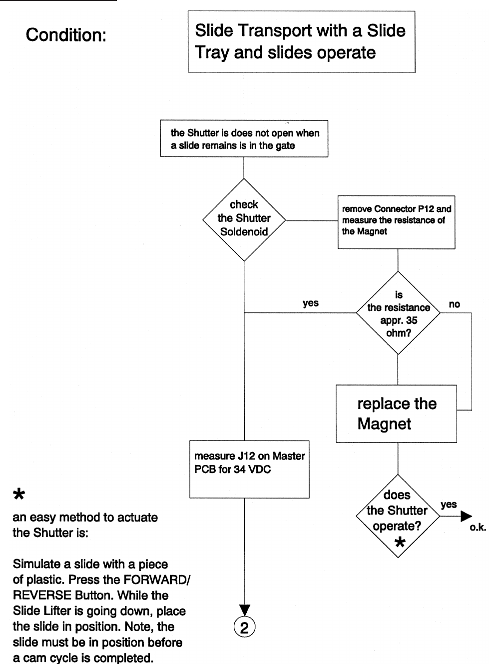
Shutter Problems
SM 2547-1 Service Manual
Kodak AG, Stuttgart 5-25 03/98

see figure
on page 28
Service Manual SM 2547-1
03/98 5-26 Kodak AG, Stuttgart
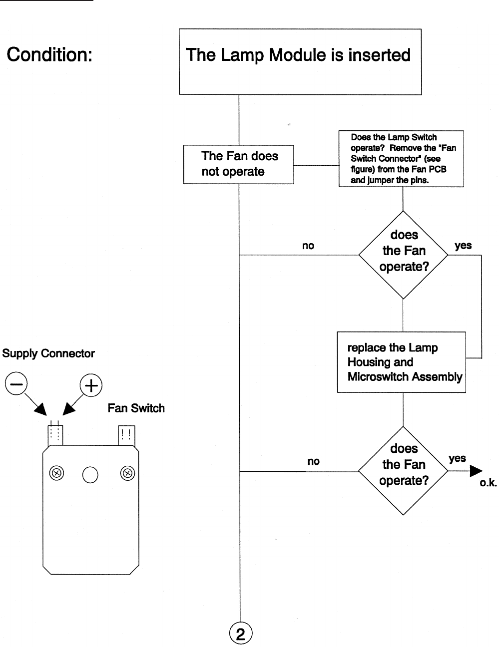
Fan Problems
SM 2547-1 Service Manual
Kodak AG, Stuttgart 5-27 03/98
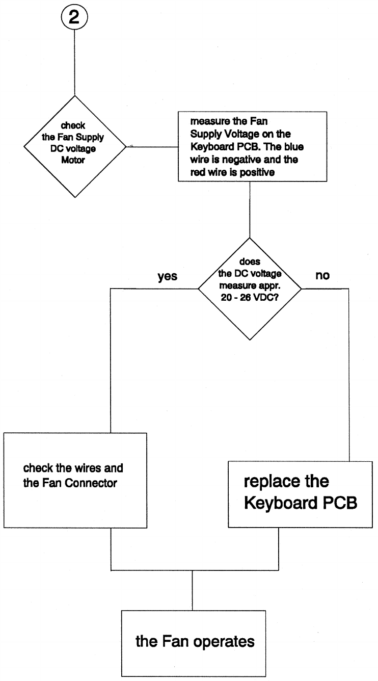
Service Manual SM 2547-1
03/98 5-28 Kodak AG, Stuttgart

Slide Obstruction in Slide Tray
Conditions for a correct transport cycle
- Check SLIDE LIFTER LEVER. In the up position, the alignment above the CENTER
HOUSING must be 3.8 mm (0.15 in.) with a tolerance of 0.2 mm (0.008 in.). If the
measurement is greater, replace the SLIDE LIFT LEVER.
- Check the CENTER HOUSING for damaged parts such as:
DRIVE RING
GEAR WHEELS
CODER DISK
Inspect whether the parts are complete. Are there damaged or broken teeth on the
wheels? If so, replace them.
SM 2547-1 Service Manual
Kodak AG, Stuttgart 5-29 03/98
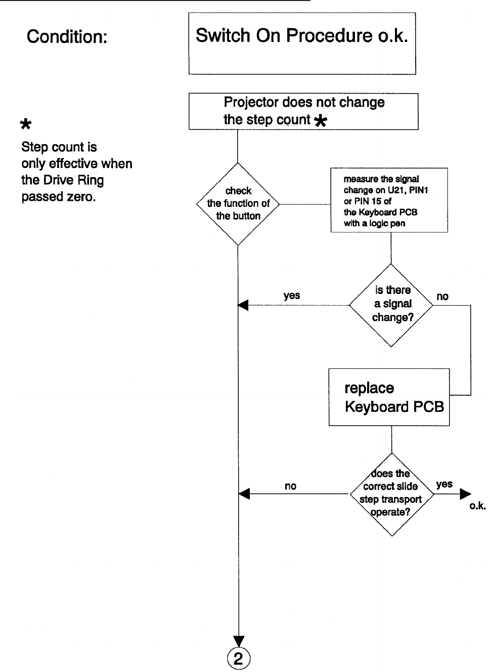
Wrong Transport Step by 80/140 SLIDE TRAY
Service Manual SM 2547-1
03/98 5-30 Kodak AG, Stuttgart
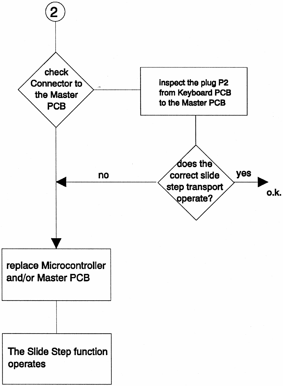
SM 2547-1 Service Manual
Kodak AG, Stuttgart 5-31 03/98
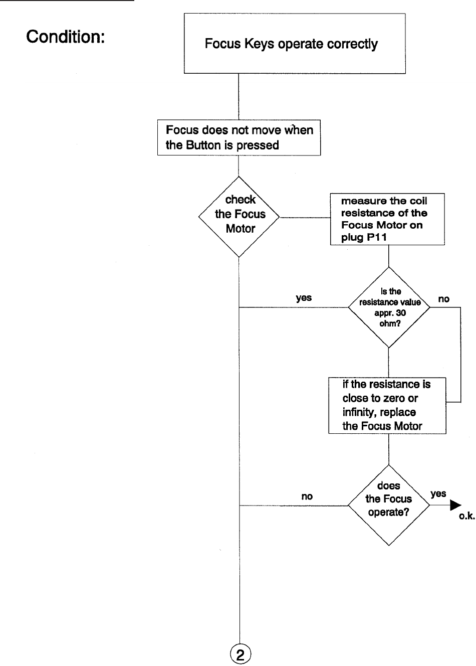
No Focus Actuation
Service Manual SM 2547-1
03/98 5-32 Kodak AG, Stuttgart
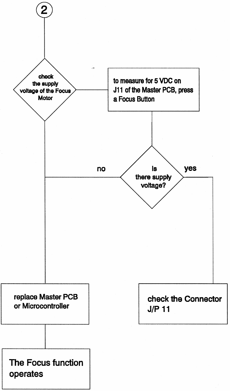
SM 2547-1 Service Manual
Kodak AG, Stuttgart 5-33 03/98
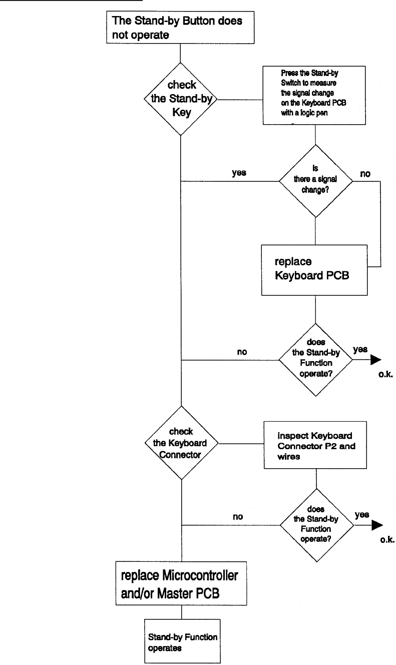
No Standby Function
Service Manual SM 2547-1
03/98 5-34 Kodak AG, Stuttgart
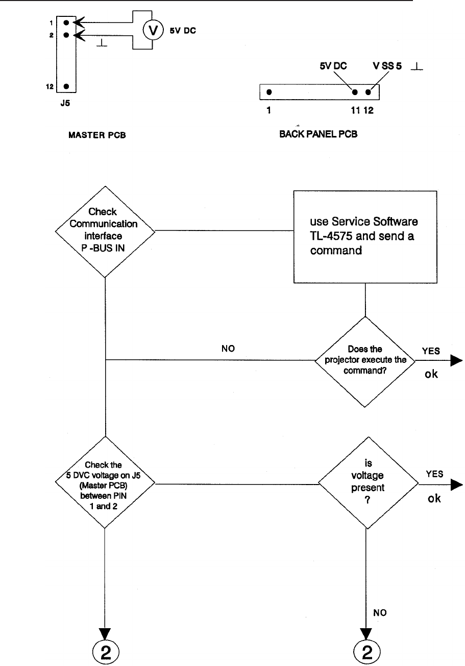
Communication Trouble 4020/5020/7020/9020 and 9020/CINE
SM 2547-1 Service Manual
Kodak AG, Stuttgart 5-35 03/98
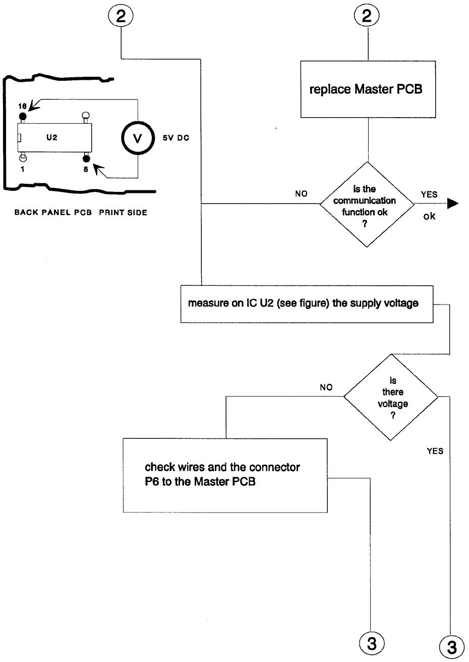
Service Manual SM 2547-1
03/98 5-36 Kodak AG, Stuttgart
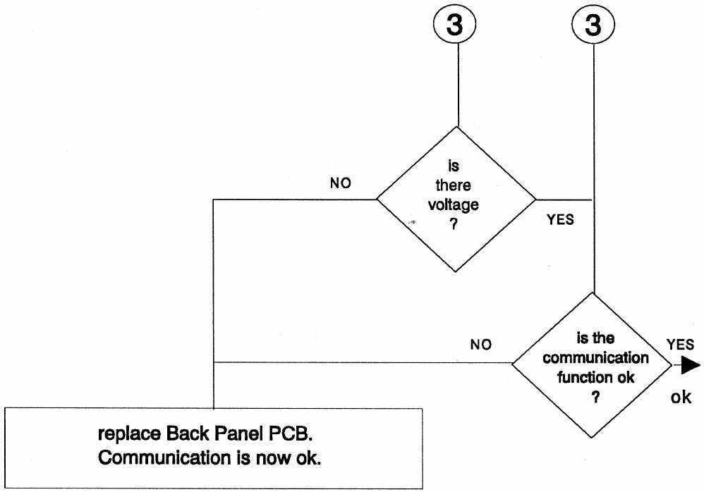
SM 2547-1 Service Manual
Kodak AG, Stuttgart 5-37 03/98
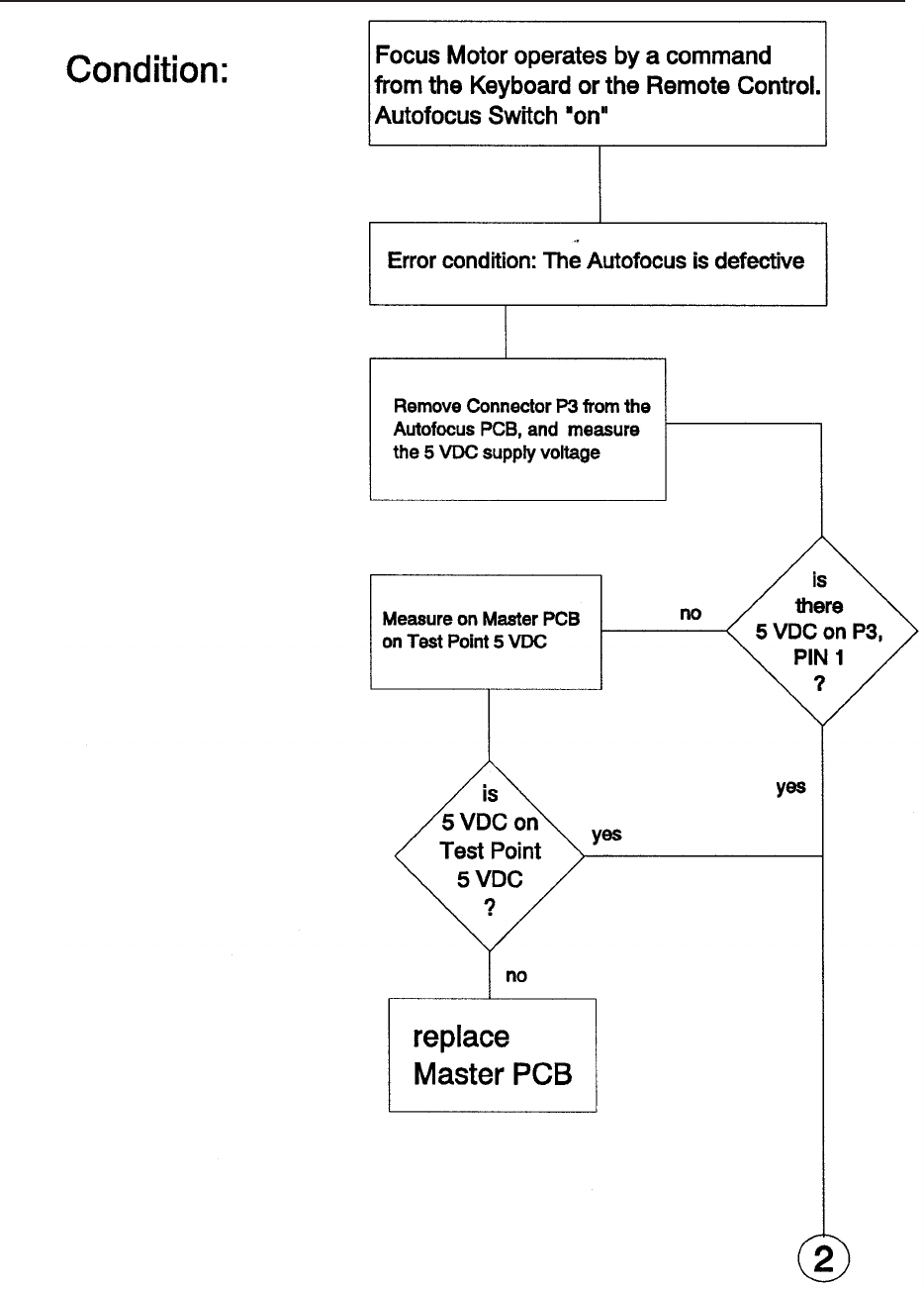
AUTO FOCUS 5020,9020 and 9020/CINE: No AUTO FOCUS Function
Service Manual SM 2547-1
03/98 5-38 Kodak AG, Stuttgart
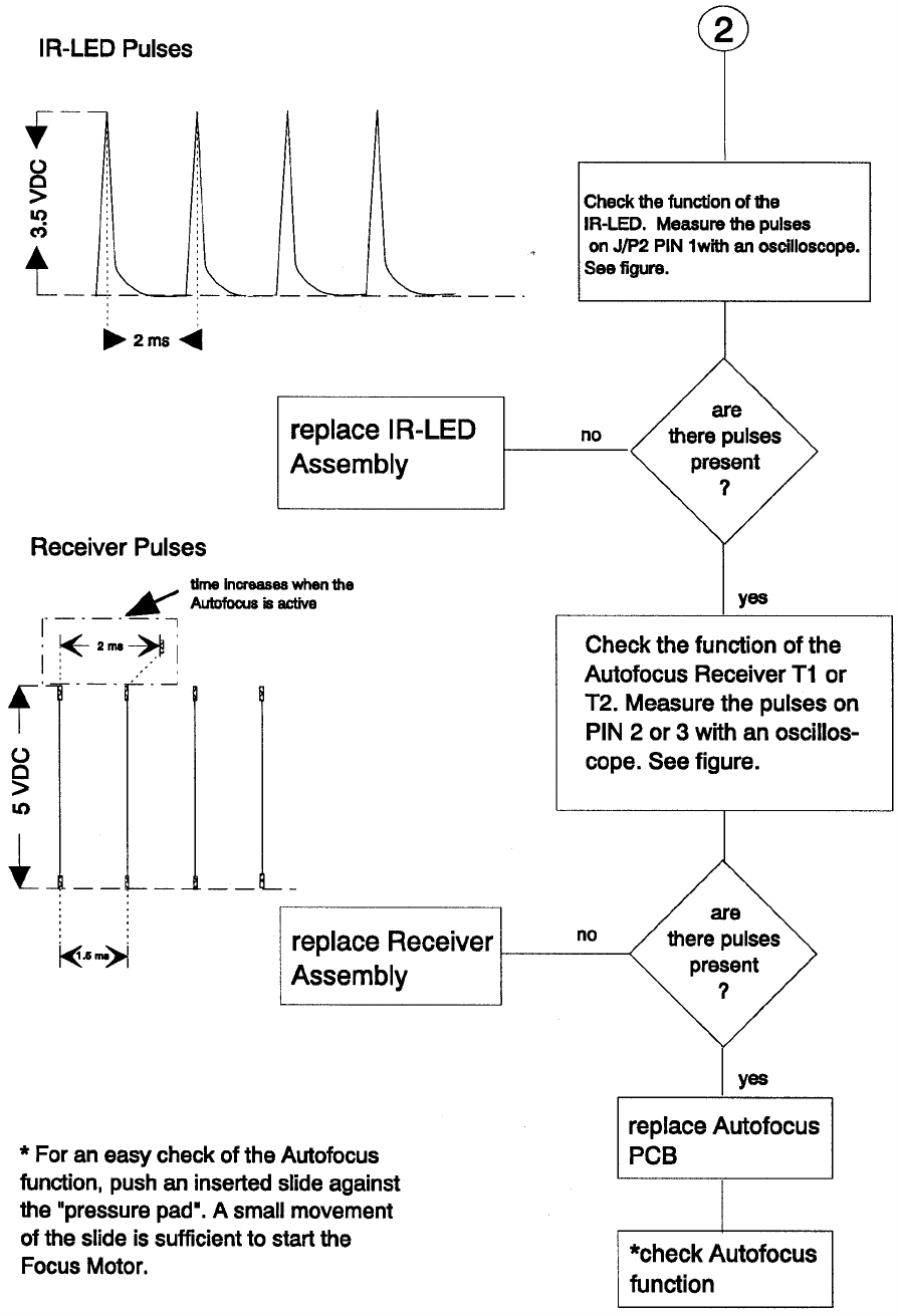
SM 2547-1 Service Manual
Kodak AG, Stuttgart 5-39 03/98

Accessory Slot 7020/9020 and 9020/CINE
Malfunction of the 12/7 PIN Module
·Check the “TR5" fuses on the ADAPTER PCB F11 and F12. Each fuse is 0.8 A.
·If the change of the fuses was not successful or the fuses operate but the ADAPTER
does not operate, use a new ADAPTER PCB.
Service Manual SM 2547-1
03/98 5-40 Kodak AG, Stuttgart
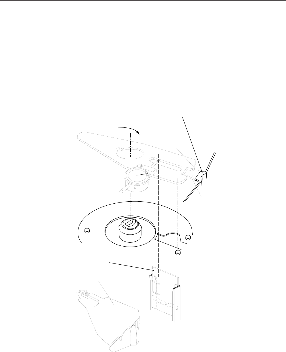
6. Projector Checking
1. Power on the Projector. If there is no function and no initialization procedure, check the primary and the
secondary Fuse F1 and F2.
Slide jam (all models)
2. To avoid slide jams check the position of the DRIVE RING. Use FIXTURE TOOL TL 622 0454 to adjust
the TRAYMOTION PCB how it is described in Modification Instruction No.1
NOTE
Take care of the spring located at the rear side of the Metal Slide (see figure 6-1). The spring must be
outside of the Slide Gate.
Nose
Metal Slide
Gap
LAMP MODULE
Align the tool
Turn the tool cw
figure 6-1
SM 5576-1 Service Manual
KODAK AG, Stuttgart 6-1 01/97
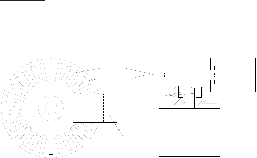
CODER DISK
·Check bolts for proper fitting (see figure 6-2).
·Take care that the slots of the CODER DISK are free of dust.
·Ensure that the CODER DISK can free rotate and do not touch the LIGHT BARRIER.
·If there are still slide transport problems replace the TRAY MOTION PCB.
MOTOR
MOTOR GEAR
BOLTS
LIGHT BARRIER
CODER DISK
SLOTS
LIGHT BARRIER
figure 6-2
Service Manual SM 5576-1
01/97 6-2 KODAK AG, Stuttgart

7. MAINTENANCE
Maintenance Intervals
After about 1 500 running hours or 500 000 SLIDE LIFTER cycles at a room temperature of 0 - 40°C (32 - 104°F)
we recommend maintenance by an authorized Kodak Service.
When the projector is operated in a dusty environment or in an enclosed area, maintenance should be done
every 1000 operating hours or less, depending on the quantity of dust.
When operating in an enclosed area, supply the necessary air and exhaust. If needed, the enclosure should have
an additional fan.
Maintenance Procedure
Open the projector. Clean with a dust cleaning device.
The following structural components should be dismounted, cleaned, if necessary parts replaced, lubricated and
assembled.
Component Page
Upper Housing 4-1
Center Housing 4-4/5/6/7
Fan, Keyboard PCB and Tray Motion PCB 4-8/9
Transformer, Power Supply PCB and Back Panel Assy 4-11
Mechanism Frame and Lens Mount 4-12
Lens Mount 4-13/14
Mechanism Frame 4-15/16/17
Cleaning of the other parts and structural components depends on how dirty they are.
See Item 4 DISASSEMBLY/ASSEMBLY.
Cleaning
It is important to clean the parts of the magazine drive and the diapositive transporter. See center housing,
mechanism frame and lens mount. These parts should be cleaned throughly with a cleaner that does not damage
the material.
SM2547-1 Service Manual
Kodak AG, Stuttgart 7-1 03/98
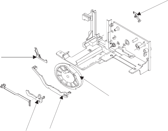
The following parts should be checked for wear and, if necessary, replaced.
The optical parts, such as LENS, CONDENSER LENS and HEAT ABSORBING GLASS should be cleaned
regularly with lens cleaner.
Ultrasonic cleaning
At present, there is no information on the reactions of the individual components. We do not suggest this method.
figure 7-1
Service Manual SM2547-1
03/98 7-2 Kodak AG, Stuttgart
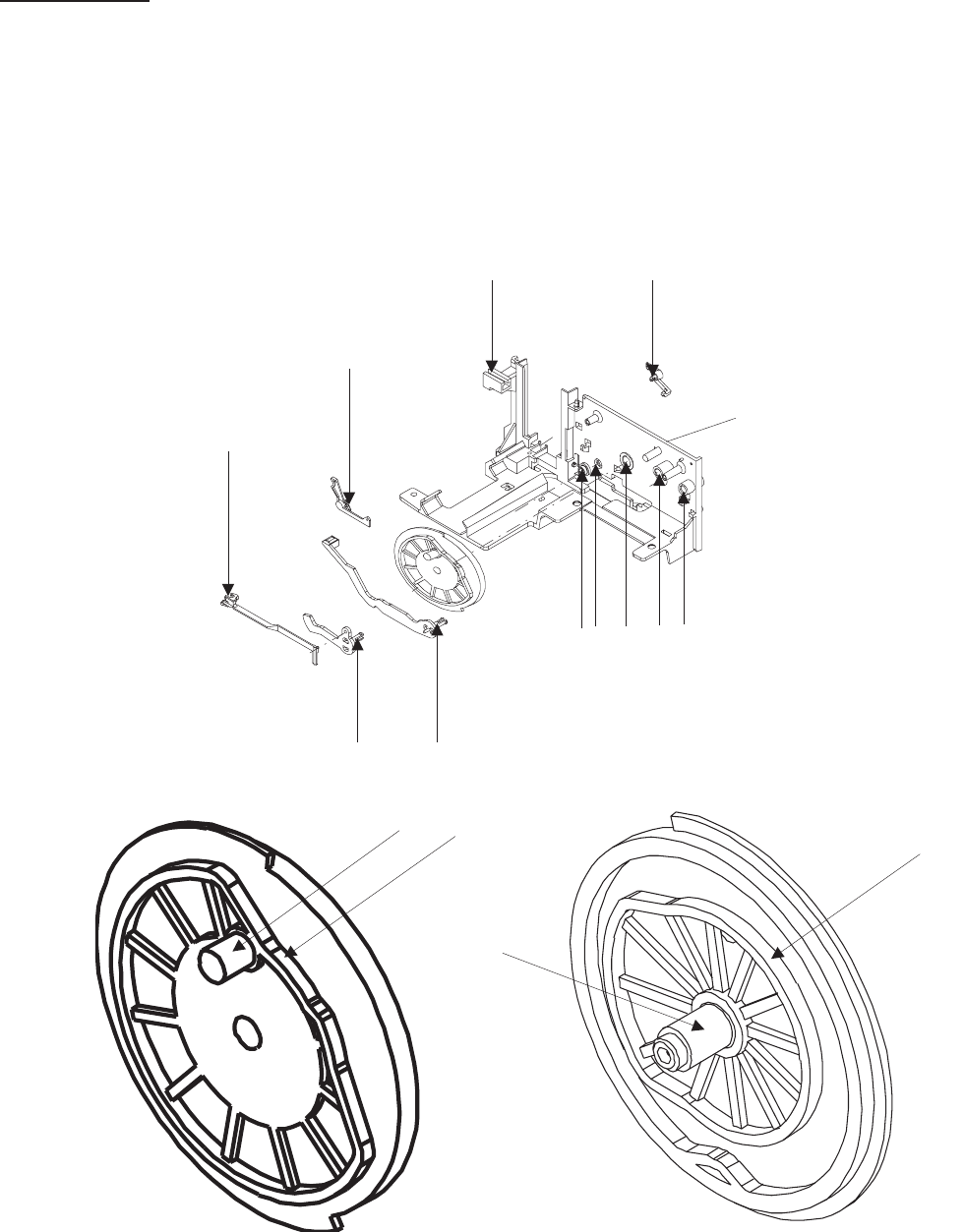
Lubrication
Use the lubricant BARRIERTA L 25 DL (50 g) No. 558 1960.
NOTE
Never use any other oil or lubricants.
Grease all arrow marked spots.
MECHANISM FRAME
figure 7-2
figure 7-3
SM2547-1 Service Manual
Kodak AG, Stuttgart 7-3 03/98
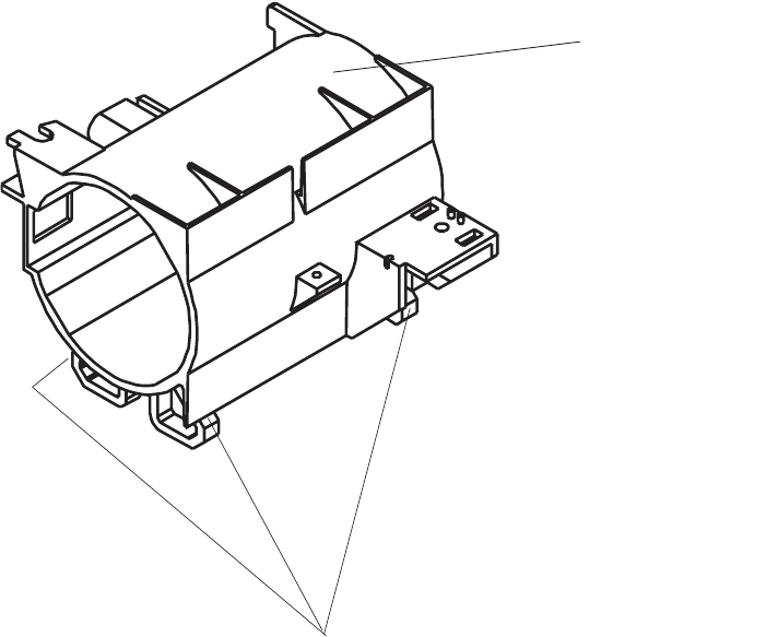
LENS MOUNT
GLIDING SURFACE
figure 7-4
Service Manual SM2547-1
03/98 7-4 Kodak AG, Stuttgart
blank page
SM2547-1 Service Manual
Kodak AG, Stuttgart 7-5 03/98

CUSTOMER EQUIPMENT SERVICES KODAK AG STUTTGART GERMANY
Kodak
