Kodak Digital Science And Imagelink Scanners A 61097 Users Manual 61097/Cover
A-61097 to the manual cae658fd-49aa-495f-9fb9-80947db0653d
2015-02-04
: Kodak Kodak-Digital-Science-And-Imagelink-Scanners-A-61097-Users-Manual-370917 kodak-digital-science-and-imagelink-scanners-a-61097-users-manual-370917 kodak pdf
Open the PDF directly: View PDF ![]() .
.
Page Count: 171 [warning: Documents this large are best viewed by clicking the View PDF Link!]
- 1 Introduction
- 2 Machine Definitions
- Display Machine Accessories
- Machine ID Number
- Display Language
- Measurement System
- Programmable Function Keys (P-Keys)
- Date Format
- Time Format
- Alarm Tone
- Document Printer/Film Writer Messages
- Print Template Setup
- Fixed Field Delimiter
- Set System Clock
- Version Numbers
- User COIN Port Protocol
- Custom Check Digit
- OI Hardware Character Set
- Save Configuration to PC
- Load Configuration from PC
- 3 Selecting the Mode Configuration Window
- Mode Definitions
- Index Format
- Image Address Display Format
- Image Address Field Widths
- Level Rules
- Batching
- Batch Level
- Batch Value
- Start of Batch Function
- End of Batch Function
- AEC Mode
- Film Mode
- Reduction Ratio
- Number of Cassettes
- Film Writer
- Character Orientation
- Image Address Print Format
- Write Definitions
- Image Management Code
- Status
- IMT Search Program Number
- Magnification
- Splice Definition
- Image Mark Sizes
- Image Polarity
- Duplex Front Location
- Film Image Orientation
- Image Offset
- Length Monitor
- Status
- Maximum Document Length
- Minimum Document Length
- Length Error Response
- Skew Monitor
- Skew Detect Status
- Skew Threshold
- Skew Error Response
- Check Stacker
- Endorser
- Endorser Status
- Endorser Mode
- Endorser Print Position
- Not Used
- Footswitch Pressed
- Footswitch Released
- Footswitch Confirmation Tone
- Patch Reader 1
- Patch Reader 2
- Patch Definition
- Transfer Patch Definition
- Film Transfer Patches
- Patch Recognition
- Bar Code
- Bar Code Reading Status
- Bar Code Type
- Number of Bar Code Characters
- Bar Codes per Document
- Distance Between Codes
- Scan Direction
- Image Processing
- Partial Read Enabled
- Minimum Partial Characters
- DSA Patch Reading Status
- Patch Horizontal Location
- End Fed Patch Reading Status
- Level Change via Bar Code
- Confirmation Tones
- Patch Detected Tone
- Bar Detected Tone
- Bar Code/Patch Tone
- OCR Status
- COIN User Channel
- Transmit Data
- Printer Control
- Image Address Print Format
- Print Position
- Special Character Set
- Primary Document Printer 1
- Document Printer Status
- Fonts/Orientation
- Print Definitions
- Secondary Document Printer 1
- Document Printer Status
- Fonts/Orientation—DP2
- Print Definitions—DP2
- Document Printer 12
- Document Printer Status—DP12
- Fonts/Orientation—DP12
- Print Definitions—DP12
- Document Sorter OFF
- Mode Overrides
- Film Definition
- 4 Installation Questionnaire
- A PPEN D IX A : System Map
- A PPEN D IX B : Function Codes
- A PPEN D IX C : Recommended Entries

DIGITAL SCIENCETM and
IMAGELINKTM Scanners
Installation Questionnaire
Instructions
Mode Setup Instructions
A-61097
Part Number 4C8894

A-61097 May 1997 1-1
1 Introduction
The KODAK DIGITAL SCIENCE™ Mode Setup Software 9000 has been
developed to enable you to customize applications using the:
• KODAK DIGITAL SCIENCE Document Scanner 9500
• KODAK DIGITAL SCIENCE Scanner/Microimager 990
• KODAK IMAGELINK Microimager 70
• KODAK IMAGELINK Microimager 70 with Advanced Function Module
• KODAK IMAGELINK Scanner 900
• KODAK IMAGELINK Scanner 923, or
• KODAK IMAGELINK Scanner/Microimager 990.
The Mode Setup Software offers a user-friendly interface which allows you
to perform an initial installation or modification of an existing setup.
The following sections describe the installation requirements, installation
procedure, logon procedure, general information regarding use of the
Mode Setup Software, the Installation Instructions and the Installation
Questionnaire, and the logout procedure.
Installation Requirements
The following system and cabling requirements should be verified prior to
attempting to use the Mode Setup Software.
The minimum system requirements include:
• IBM or IBM-compatible personal computer
• 640K RAM
• 1.2 MB hard disk space
• 720K 3 1/2" disk drive
• monochrome or color display
The cabling requirements include:
• 9-pin serial port adapter* or a 25-pin serial port adapter**
*Available through Kodak Parts Services using tool number TL-4219.
** Available through Businessland using part number 984956.

1-2 A-61097 May 1997
Software Installation Procedure
Follow these steps to install the software:
1. Insert the Mode Setup Software diskette into the drive.
2. Type A:INSTALL next to the DOS prompt and press Return/Enter.
If the disk drive on your unit is not designated as the A drive, substitute
the correct drive designation in this command string.
Microimager IL70 * IL70 AFM
Scanner IL900 * IL923
Microimager/Scanner DS990 * Scanner DS9500
Mode Setup Software
Copyright (c) 1989-1997
Eastman Kodak Company
All Rights Reserved
Press Any Key to Install, ESCAPE to Exit
3. Press any key.
Mode Setup Software
Drive To Install From: A
Drive To Install To: C
Directory To Be Installed To:
\SETUP
Directory Information
ESCAPE to Abort

A-61097 May 1997 1-3
4. Enter the desired drive and directory designations and press Enter.
Drive To Install From: A
Drive To Install To: C
Directory To Be Installed To:
\SETUP
Directory Information
ESCAPE to Abort
[Press ENTER to Accept, any other key to Edit]
5. Press Enter to continue the logon procedure. Press any other key to
alter the drive and directory designations.
Mode Setup Software
Please Wait While Files Are Being Copied To Your
Destination Drive.
Use Existing Directory ([Y/N]?
Hit [N]o to Select New Directory
6. Enter an N to abort and designate a different directory. Enter a Y to
continue, replacing the files within the designated directory.

1-4 A-61097 May 1997
During the installation procedure, the following window will appear if you
don’t have the files and buffers set correctly in the config.sys file:
Please Wait While Files
Are Being Copied ToYour
Destination Drive.
The CONFIG.SYS
File Needs To
Be Checked To Make
Sure That
BUFFERS=40 FILES=40
INSTALLING
Mode Setup Software
Next, the following windows will appear:
Please Wait While Files
Are Being Copied To Your
Destination Drive.
INSTALLING
Mode Setup Software
Please Wait
Copying File: setup.zip
INSTALLING
Mode Setup Software

A-61097 May 1997 1-5
FILE COPY COMPLETE
Please enter the name of the registered user below:
_ _ _ _ _ _ _ _ _ _ _ _ _ _ _ _ _ _ _ _ _ _ _ _ _ _ _ _ _ _ _ _ _ _ _ _
Please Wait While Files
Are Being Copied To Your
Destination Drive.
REGISTRATION
7. Type in user name. Press Return/Enter.
Type “setup” in c:\setup directory to start Mode Setup
8. Press any key to return to DOS.
9. Eject the Mode Setup Software diskette.
10. Type: cd setup. The SETUP directory is displayed.
11. Type: setup. This starts the program.
1-6 A-61097 May 1997
Logon Procedure
After the installation procedure has been performed, follow these steps to
log on to the Mode Setup Software:
1. Access DOS.
2. Change the directory to correspond to the directory designated during
the installation procedure.
3. Type setup and press Return/Enter.
* EASTMAN KODAK COMPANY *
* Model 30 *
* Model 70/AFM * Model 70 *
* Model 900 * Model 923 *
* Model DS990 * Model DS9500 *
This software is the property of
Eastman Kodak Company.
It is not to be sold or leased
in any form. Use by any other
individual is illegal and subject
to penalties under the copyright
laws of the United States.
Connect via RS-232
Connect via Modem
Exit
Version
3.30
Release Date
MM-DD-YY
Copyright
Eastman Kodak Company
1989-1997
4. Select Connect via RS-232 and press Return/Enter.
KODAK IMAGELINK (tm) / DIGITAL SCIENCE (tm)
Microimager Models 30 & 70
Microimager Model 70/AFM
Scanner 900 & 923
Microimager/Scanner DS990
Scanner DS9500
1) Attach RS-232 Cable
2) Turn Operator Power Switch ON
3) Press “ENTER/RETURN” Key
Continue
Exit

A-61097 May 1997 1-7
5. Select Continue.
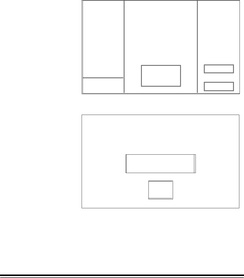
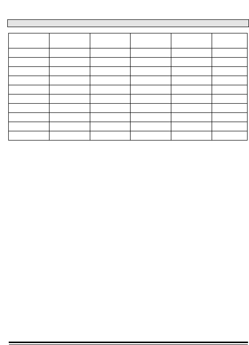
Display Machine Accessories
Machine ID Number
Display Language
Measurement System
Programmable Function Keys
Date Format
Time Format
Alarm Tone
Doc Printer/Film Writer Msg
DP-12 Print Template
Fixed Field Delimiter
Set System Clock
Version Numbers
User COIN Port Protocol
Custom Check Digit
OI Hardware Character Set
Save Configuration to PC
Load Configuration from PC
Mode Configuration
End Session
Mainframe Configuration
MACHINE STATE
Using the Mode Setup Software
This section provides guidelines and conventions that will assist you in
using the Mode Setup Software.
• There are two levels of definitions: Machine definitions, which apply to
all modes; and Mode definitions, which apply to one mode.
• Each defined option requires you to select a displayed option or enter a
value.
• If asked to select an option:
— Use the arrow keys to position the highlight cursor over the desired
option.
— Press the Return/Enter key.
• If asked to enter a value:
— Typically, the highlight cursor will appear over the input field, if it
does not, use the arrow keys to position the highlight cursor over the
input field.
— Enter (type) the desired value, using the keyboard or numeric
keypad.
— Press the Return/Enter key.

1-8 A-61097 May 1997
• Each window should contain an option entitled Previous Menu.
Typically, you are returned to the previous menu after completing a
definition. If you are not returned to the previous menu after completing
a definition, or you want to return without altering the default or
previously defined value, select the Previous Menu option:
— Use the arrow keys to position the highlight cursor over the Previous
Menu option or press the PAGEDOWN key to automatically position
the highlight cursor over the Previous Menu option.
— Press the Return/Enter key.
• If you receive a message indicating that an accessory is not installed,
press the Return/Enter key to continue. This message indicates that
the option selected requires an accessory which is not physically
installed and/or properly defined to the software. In either instance,
contact your Kodak service representative to properly install and/or
define the accessory.
• If you receive a message that indicates a selection is not available,
press the Return/Enter key to continue. This message indicates that
the option selected is not available in the mode selected, or is not
available for the machine configuration.
Using the Mode Setup Software Questionnaire and Instructions
There are two pieces of documentation designed for use with the Mode
Setup Software: the Installation Instructions, which provide information on
how to install, access and use the software to define the available options;
and the Installation Questionnaire, which provides a convenient form on
which to record all of the machine and mode definitions.
The Installation Instructions describe all of the available options which can
be defined using the Mode Setup Software.
NOTE: Not all options are available using a given machine configuration.
Hence, each definition is accompanied by a configuration key
which indicates whether or not the option is available for each
machine configuration. If you attempt to define an option which is
not valid under your machine configuration, you will receive a
message which indicates that the option is not available. Simply
press the Return/Enter key to continue.
Follow the Installation Instructions in order to define all of the available
options, recording each definition on the Installation Questionnaire form,
found in chapter 4. The Installation Questionnaire form requires that you
write your selections in the space provided. Due to space limitations,
Appendix C: Recommended Questionnaire Entries contains
recommended shorthand entries for the various options you may enter.
This is provided so that there is consistency among users, making it
easier for other users to decipher your selections.

A-61097 May 1997 1-9
Logout Procedure
Once you have completed the installation, the following sequence of steps
may be used to log out of the system.
From the Mode Configuration window:
1. Select Save & End Session if you wish to save all of the definitions or
Don’t Save & End Session if you do not wish to save all of the
definitions.
You will be returned to the Configuration window.
2. Select End Session from the Configuration window.
Display Machine Accessories
Machine ID Number
Display Language
Measurement System
Programmable Function Keys
Date Format
Time Format
Alarm Tone
Doc Printer/Film Writer Msg
DP-12 Print Template
Fixed Field Delimiter
Set System Clock
Version Numbers
User COIN Port Protocol
Custom Check Digit
OI Hardware Character Set
Save Configuration to PC
Load Configuration from PC
Mode Configuration
End Session
Mainframe Configuration
MACHINE STATE
Continue Session
End Session
Please confirm ending session
3. Select End Session to exit to DOS or Continue Session if you do not
want to exit at this time.

A-61097 May 1997 2-1
2 Machine Definitions
The following section lists the items on the Mainframe Configuration Menu
that may be selected for definition.
Display Machine Accessories
Machine ID Number
Display Language
Measurement System
Programmable Function Keys
Date Format
Time Format
Alarm Tone
Doc Printer/Film Writer Msg
DP-12 Print Template
Fixed Field Delimiter
Set System Clock
Version Numbers
User COIN Port Protocol
Custom Check Digit
OI Hardware Character Set
Save Configuration to PC
Load Configuration from PC
Mode Configuration
End Session
Mainframe Configuration
MACHINE STATE
The following list appears for each option. A black square indicates that
the option is available on that machine. A white square indicates that the
option is not available on that machine. An example is illustrated below:
■Microimager 70 ❏Microimager 70/AFM ■Scanner 900
■Scanner 923 ■Scanner/Microimager 990 ■Scanner 9500

2-2 A-61097 May 1997
Display Machine Accessories
This option displays the status of the various machine accessories and is
for viewing only; no selections or entries are made.
■Microimager 70 ■Microimager 70/AFM ■Scanner 900
■Scanner 923 ■Scanner/Microimager 990 ■Scanner 9500
1. Select Display Machine Accessories.
2. Press Return/Enter to close the Accessory Status window.
Status
Display Machine Accessories
Machine ID Number
Display Language
Measurement System
Programmable Function Keys
Date Format
Time Format
Alarm Tone
Doc Printer/Film Writer Msg
DP-12 Print Template
Fixed Field Delimiter
Set System Clock
Version Numbers
User COIN Port Protocol
Custom Check Digit
OI Hardware Character Set
Save Configuration to PC
Load Configuration from PC
Mode Configuration
End Session
Accessory
Endorser
Check Stacker
Image Marker
Film Writing
Adv Doc Control
Patch Head #1
Patch Head #2
Front BC Board
Front DSA
Rear BC Board
Rear DSA
Print Controller
Primary DP-1
Secondary DP-1
Doc Printer 12
OCR
Document Sorter
Not Present
Not Present
Present
Present
Present
Present
Not Present
Not Present
Present
Not Present
Not Present
Mainframe Configuration
MACHINE STATE
NOTE: On scanners 900, 923, and 9500, Image Marker and Film Writing
are not available.
On a machine with DSA:
Patch Head #2 = N/A
Front DSA = 990/923/IL70
Rear DSA = 990 D Only

A-61097 May 1997 2-3
Machine ID Number
This option establishes a unique identification number for each unit in a
multiple-unit installation. The default is 00.
■Microimager 70 ■Microimager 70/AFM ■Scanner 900
■Scanner 923 ■Scanner/Microimager 990 ■Scanner 9500
1. Select Machine ID Number.
2. Enter a number from 00-99.
Display Machine Accessories
Machine ID Number
Display Language
Measurement System
Programmable Function Keys
Date Format
Time Format
Alarm Tone
Doc Printer/Film Writer Msg 5
DP-12 Print Template
Fixed Field Delimiter
Set System Clock
Version Numbers
User COIN Port Protocol
Custom Check Digit
OI Hardware Character Set
Save Configuration to PC
Load Configuration from PC
Mode Configuration
End Session
Mainframe Configuration
MACHINE STATE
Enter machine id below
00
To Change: Enter Value
To Retain: Press Enter

2-4 A-61097 May 1997
Display Language
This option defines the primary display language. The default is English.
■Microimager 70 ■Microimager 70/AFM ■Scanner 900
■Scanner 923 ■Scanner/Microimager 990 ■Scanner 9500
1. Select Display Language.
2. Select the desired language option.
Display Machine Accessories
Machine ID Number
Display Language
Measurement System
Programmable Function Keys
Date Format
Time Format
Alarm Tone
Doc Printer/Film Writer Msg
DP-12 Print Template
Fixed Field Delimiter
Set System Clock
Version Numbers
User COIN Port Protocol
Custom Check Digit
OI Hardware Character Set
Save Configuration to PC
Load Configuration from PC
Mode Configuration
End Session
MACHINE STATE
English
Other Language
Previous Menu
Language
Mainframe Configuration
NOTE: Other Language should be selected only if a foreign language
prom has been installed. If selected, indicate which foreign
language prom has been installed when filling in the Installation
Questionnaire.

A-61097 May 1997 2-5
Measurement System
This option defines the primary measurement system. English uses inches
as the primary unit of measure. Metric uses millimetres as the primary unit
of measure. The default is English.
■Microimager 70 ■Microimager 70/AFM ■Scanner 900
■Scanner 923 ■Scanner/Microimager 990 ■Scanner 9500
1. Select Measurement System.
2. Select the desired unit of measurement.
Display Machine Accessories
Machine ID Number
Display Language
Measurement System
Programmable Function Keys
Date Format
Time Format
Alarm Tone
Doc Printer/Film Writer Msg
DP-12 Print Template
Fixed Field Delimiter
Set System Clock
Version Numbers
User COIN Port Protocol
Custom Check Digit
OI Hardware Character Set
Save Configuration to PC
Load Configuration from PC
Mode Configuration
End Session
MACHINE STATE
English
Metric
Previous Menu
Units
Mainframe Configuration
2-6 A-61097 May 1997
Programmable Function Keys (P-Keys)
This option defines the functions performed by the programmable keys.
Refer to Appendix B: Function Codes to determine which function codes
and formats to use when programming the P-Keys.
■Microimager 70 ■Microimager 70/AFM ■Scanner 900
■Scanner 923 ■Scanner/Microimager 990 ■Scanner 9500
1. Select Programmable Function Keys.
Display Machine Accessories
Machine ID Number
Display Language
Measurement System
Programmable Function Keys
Date Format
Time Format
Alarm Tone
Doc Printer/Film Writer Msg
DP-12 Print Template
Fixed Field Delimiter
Set System Clock
Version Numbers
User COIN Port Protocol
Custom Check Digit
OI Hardware Character Set
Save Configuration to PC
Load Configuration from PC
Mode Configuration
End Session
MACHINE STATE
Mainframe Configuration
DefinitionKey
P1
P2
P3
P4
P5
P6
P7
P8
P9
P10
Prev Previous Menu
A-61097 May 1997 2-7
The default values are displayed in the Key Definition table.
The following values apply only to the Scanner 9500.
DefinitionKey
P1
P2
P3
P4
P5
P6
P7
P8
P9
P10
Prev
f37
f98f38
f01,01
f01,02
f01,03
f01,04
f01,05
f01,06
f01,07
ff01,08
Previous Menu
Calibrate
Stop, End of Job
Change to Mode 1
Change to Mode 2
Change to Mode 3
Change to Mode 4
Change to Mode 5
Change to Mode 6
Change to Mode 7
Change to Mode 8
The following values apply only to the Microimager 70 and Microimager 70/
AFM:
DefinitionKey
P1
P2
P3
P4
P5
P6
P7
P8
P9
P10
f04,2
f45
f09
f08
f33
f30
f44
f46
f07
f35
Count only, toggle
Print test
Total document count
Last Image Address
Roll number
Amount of film remaining
Omit printing on next document only
Print position
Level 0
Cassette ID number
The following default values apply only to the Scanner 900/923.
DefinitionKey
P1
P2
P3
P4
P5
P6
P7
P8
P9
P10
f37
f98f38
f01,01
f01,02
f01,03
f01,04
f01,05
f01,06
f01,07
ff01,08
Calibrate
Stop, End of Job
Change to Mode 1
Change to Mode 2
Change to Mode 3
Change to Mode 4
Change to Mode 5
Change to Mode 6
Change to Mode 7
Change to Mode 8

2-8 A-61097 May 1997
The following default values apply only to the Scanner/Microimager 990:
DefinitionKey
P1
P2
P3
P4
P5
P6
P7
P8
P9
P10
f04,2
f45
f09
f08
f37
f30
f44
f46
f07
f98f38
Count only, toggle
Print test
Total document count
Last Image Address
Calibrate
Amount of film remaining
Omit printing on next document only
Print position
Level 0
Stop, End-of-Job
To enter a function code, type an f (lower case) followed by a two-digit
code (i.e., f04). Any additional information, such as a zero (0) to disable a
function, a one (1) to enable a function, or a two (2) to toggle a function, is
entered by typing a comma (,) followed by the additional information (i.e.,
f04,1 enables counting only).
Multiple function codes are entered as a string of individual function codes
with no spaces or delimiters in between (i.e., f98f38 stops the machine
and then issues an end-of-job indicator).
When using a Microimager 70 without the Advanced Function Module
installed, only two of the P-Keys are programmable: P5 and P10.
When using a Microimager 70 with the Advanced Function Module
installed, Scanner 900, Scanner 923, Scanner/Microimager 990, or
Scanner 9500, all P-Keys are programmable.
P-Keys are programmed using the following sequence of steps:
1. Select a P-Key (P1 – P10).
2. Press Return/Enter.
3. Enter the desired function.
Repeat this sequence for each P-Key you wish to (re)program.
A-61097 May 1997 2-9
Date Format
This option defines the date display format, both the date format and
delimiter. Refer to Description 1: Date Format Samples for a description
of the available formats. The default is mmddyy. The default delimiter is a
slash (/).
❏Microimager 70 ■Microimager 70/AFM ■Scanner 900
■Scanner 923 ■Scanner/Microimager 990 ■Scanner 9500
1. Select Date Format.
2. Select a date format.
3. Select a date delimiter.
Example
Display Machine Accessories
Machine ID Number
Display Language
Measurement System
Programmable Function Keys
Date Format
Time Format
Alarm Tone
Doc Printer/Film Writer Msg
DP-12 Print Template
Fixed Field Delimiter
Set System Clock
Version Numbers
User COIN Port Protocol
Custom Check Digit
OI Hardware Character Set
Save Configuration to PC
Load Configuration from PC
Mode Configuration
End Session
MACHINE STATE
Date Format
mmddyy
mmdd
ddmmmyy
ddmmm
mmyy
yddd
yyddd
yymmdd
ddmmyy
mmmddyyyy
12/25/92
12/25
25-DEC-92
25-DEC
12/92
2-359
92-359
92.12.25
25 12 92
DEC-25-1992
Mainframe Configuration
Date Delimiter
Slash
Dash
Period
Space
No Delimiter
Previous Menu
mm
mmm
dd
ddd
y
yy
yyyy
("/")
("-")
(".")
(" ")
= [01-12]
= [JAN,FEB]
= [01-31]
= [001-366]
= [0-9]
= [00-99]
= 1990-2000
2-10 A-61097 May 1997
Description 1: Date Format Samples
Sample Date
March 1, 1991 Slash Dash Period Space None
mmddyy 03/01/91 03/01/91 03.01.91 03 01 91 030191
mmdd 03/01 03-01 03.01 03 01 0301
ddmmmyy 01/MAR/91 01-MAR-91 01.MAR.91 01 MAR 91 01MAR91
ddmmm 01/MAR 01-MAR 01.MAR 01 MAR 01MAR
mmyy 03/91 03-91 03.91 03 91 0391
yddd 1/060 1-060 1.060 1 060 1060
yyddd 91/060 91-060 91.060 91 060 91060
yymmdd 91/03/01 91-03-91 91.03.01 91 03 01 910301
ddmmyy 01/03/91 01-03-91 01.03.91 01 03 91 010391
mmmddyyyy MAR/01/1991 MAR-01-1991 MAR.01.1991 MAR 01 1991 MAR011991
A-61097 May 1997 2-11
Time Format
This option defines the time display format. Refer to Description 2: Time
Format Samples for a description of the available formats. The default is
12 hour with AM/PM.
❏Microimager 70 ■Microimager 70/AFM ■Scanner 900
■Scanner 923 ■Scanner/Microimager 990 ■Scanner 9500
1. Select Time Format.
2. Select a specific time format.
Display Machine Accessories
Machine ID Number
Display Language
Measurement System
Programmable Function Keys
Date Format
Time Format
Alarm Tone
Doc Printer/Film Writer Msg
DP-12 Print Template
Fixed Field Delimiter
Set System Clock
Version Numbers
User COIN Port Protocol
Custom Check Digit
OI Hardware Character Set
Save Configuration to PC
Load Configuration from PC
Mode Configuration
End Session
MACHINE STATE
Set Time Format
12 Hour with AM/PM
12 Hour without AM/PM
24 Hour
Previous Menu
Mainframe Configuration
Description 2: Time Format Samples
Time Format What Is Printed
12 hour with AM/PM 5:00 PM
12 hour without AM/PM 5:00
24 hour 17:00

2-12 A-61097 May 1997
Alarm Tone
This option defines tone or pitch of the audible alarm. The default is High.
❏Microimager 70 ■Microimager 70/AFM ■Scanner 900
■Scanner 923 ■Scanner/Microimager 990 ■Scanner 9500
1. Select Alarm Tone.
2. Select the desired alarm tone pitch.
Display Machine Accessories
Machine ID Number
Display Language
Measurement System
Programmable Function Keys
Date Format
Time Format
Alarm Tone
Doc Printer/Film Writer Msg
DP-12 Print Template
Fixed Field Delimiter
Set System Clock
Version Numbers
User COIN Port Protocol
Custom Check Digit
OI Hardware Character Set
Save Configuration to PC
Load Configuration from PC
Mode Configuration
End Session
MACHINE STATE
Low Tone
High Tone
Previous Menu
Alarm Tone
Mainframe Configuration

A-61097 May 1997 2-13
Document Printer/Film Writer Messages
This option defines messages that may be printed by a document printer
or film writer.
❏Microimager 70 ■Microimager 70/AFM ■Scanner 900
■Scanner 923 ■Scanner/Microimager 990 ■Scanner 9500
1. Select Doc Printer/Film Writer Msg.
Messages are limited to thirty-eight (38) characters for Document
Printer 1 and 2, and Film Writer, and 12 characters for the DP12, and
can include any character that can be input from a standard keyboard
(alphabetic, numeric, and special characters).
NOTE: Alphabetic characters are automatically converted to upper case.
Display Machine Accessories
Machine ID Number
Display Language
Measurement System
Programmable Function Keys
Date Format
Time Format
Alarm Tone
Doc Printer/Film Writer Msg
DP-12 Print Template
Fixed Field Delimiter
Set System Clock
Version Numbers
User COIN Port Protocol
Custom Check Digit
OI Hardware Character Set
Save Configuration to PC
Load Configuration from PC
Mode Configuration
End Session
MACHINE STATE
Mainframe Configuration
2-14 A-61097 May 1997
Message 0 is predefined and cannot be changed.
Messages 1 through 9 are programmable using the following sequence of
steps:
1. Select a message number.
2. Press Return/Enter.
3. Enter the desired message text.
4. Press Return/Enter.
DefinitionMsg
0
1
2
3
4
5
6
7
8
9
Prev Previous Menu
Diagnostic Message - No Entry Allowed.

A-61097 May 1997 2-15
Print Template Setup
This option defines as many as ten (10) unique print templates.
The template definitions are used when programming Document Printer
12 print definitions. The default print template is Print Template 1, which
prints Full IA w/No Delimiters on Line 1.
❏Microimager 70 ■Microimager 70/AFM ■Scanner 900
■Scanner 923 ■Scanner/Microimager 990 ■Scanner 9500
1. Select DP-12 Print Template.
2. Select a print template (1–10).
Display Machine Accessories
Machine ID Number
Display Language
Measurement System
Programmable Function Keys
Date Format
Time Format
Alarm Tone
Doc Printer/Film Writer Msg
DP-12 Print Template
Fixed Field Delimiter
Set System Clock
Version Numbers
User COIN Port Protocol
Custom Check Digit
OI Hardware Character Set
Save Configuration to PC
Load Configuration from PC
Mode Configuration
End Session
MACHINE STATE
Print Template 1
Print Template 2
Print Template 3
Print Template 4
Print Template 5
Print Template 6
Print Template 7
Print Template 8
Print Template 9
Print Template 10
Previous Menu
Print Templates
Mainframe Configuration

2-16 A-61097 May 1997
1. Follow these steps for each line/item to be printed (maximum twelve
per template):
a. Select the next available item number (or Item 1 if this is the first
item).
b. Enter a line number corresponding to the line number on the print
template master.
c. Select one or more of the print items listed (maximum three items
per line).
NOTE: Anything over 12 characters will be truncated.
Document Printer 12 Print Template #
1
2
3
4
5
6
7
8
9
10
11
12
Previous Menu
Item Line Print Item
01 <IA-No Del>
Full IA w/ No Delimiter
Full IA w/ FF Delimiter
Fixed Field Only
Indexed Fields Only
Current Field Level
Number of Spaces to Indent
Current Day
Current Date
Current Time
Roll Number
Total Document Count
Message 1 - 9
Check Digit
Nothing Printed
Previous Menu
Print Items
If Number Spaces to Indent is selected, you must select the desired
number of spaces.
No # of Spaces (1..12)
TO CHANGE: Enter Value
TO RETAIN: Press Enter
A-61097 May 1997 2-17
If Check Digit is selected, the following window is displayed:
Document Printer 12 Print Template #
1
2
3
4
5
6
7
8
9
10
11
12
Previous Menu
Item Line Print Item
01 <IA-No Del> <Message 1>
Mod 7A - IA Only
Mod 11A - IA Only
Mod 7B - IA Only
Mod 7B - Full IA
Mod 10 - IA Only
Mod 10 - Full IA
Mod 11B - IA Only
Mod 11B - Full IA
Custom - IA Only
Custom - Full IA
Previous Menu
Check Digit
3. Select the desired check digit calculation.
If an option that indicates IA Only is chosen, the level fields of the
Image Address will be printed; the Fixed Field will not be printed. If an
option which indicates Full IA is chosen, the Fixed Field and Level
fields of the Image Address will be printed.
NOTE: If Custom – IA Only or Custom – Full IA is chosen, the Check
Digit options must be defined.
If Message Number is selected, the following window is displayed:
Document Printer 12 Print Template #
1
2
3
4
5
6
7
8
9
10
11
12
Previous Menu
Item Line Print Item
01 <IA-No Del> <Message 1>
Message Number 1
Message Number 2
Message Number 3
Message Number 4
Message Number 5
Message Number 6
Message Number 7
Message Number 8
Message Number 9
Previous Menu
Message Number
4. Select the desired message number.
The Document Printer 12 may print as many as twelve (12) lines per
document; each print line can be up to twelve (12) characters long and
contain as many as three print items. The location of the twelve lines is
defined in terms of a master template which is thirty-eight (38) lines high
and twelve characters wide for the small font, and twenty-six (26) lines
high and twelve (12) characters wide for the large font.

2-18 A-61097 May 1997
The master template is designed to assist you in the placement of
information printed by the Document Printer 12.
Follow these steps to use the master templates:
1. Obtain a sample of the customer’s document(s).
2. Determine the starting print position (how far from the leading edge of
the document printed information should appear).
3. Draw a line on the sample document which corresponds to the starting
print position.
4. Copy the master template onto a transparency.
5. Align the top (dotted) line of the master template with the line drawn on
the sample document to achieve proper vertical placement.
6. Position the master template so that the window is aligned with the
position of the Document Printer 12 in the transport to achieve proper
horizontal placement.
The area in which printed information may appear should now be
highlighted.
7. Identify the line numbers which correspond to the area(s) of the
customer document where you want the printed information to appear.
Use these line numbers when defining the print template(s).
NOTE: The placement of printed information will vary slightly due to a
number of factors, including document transport speed. Expect a
variation of 0.125 inch between the print template and starting
print position definitions and the location of actual printed
information.
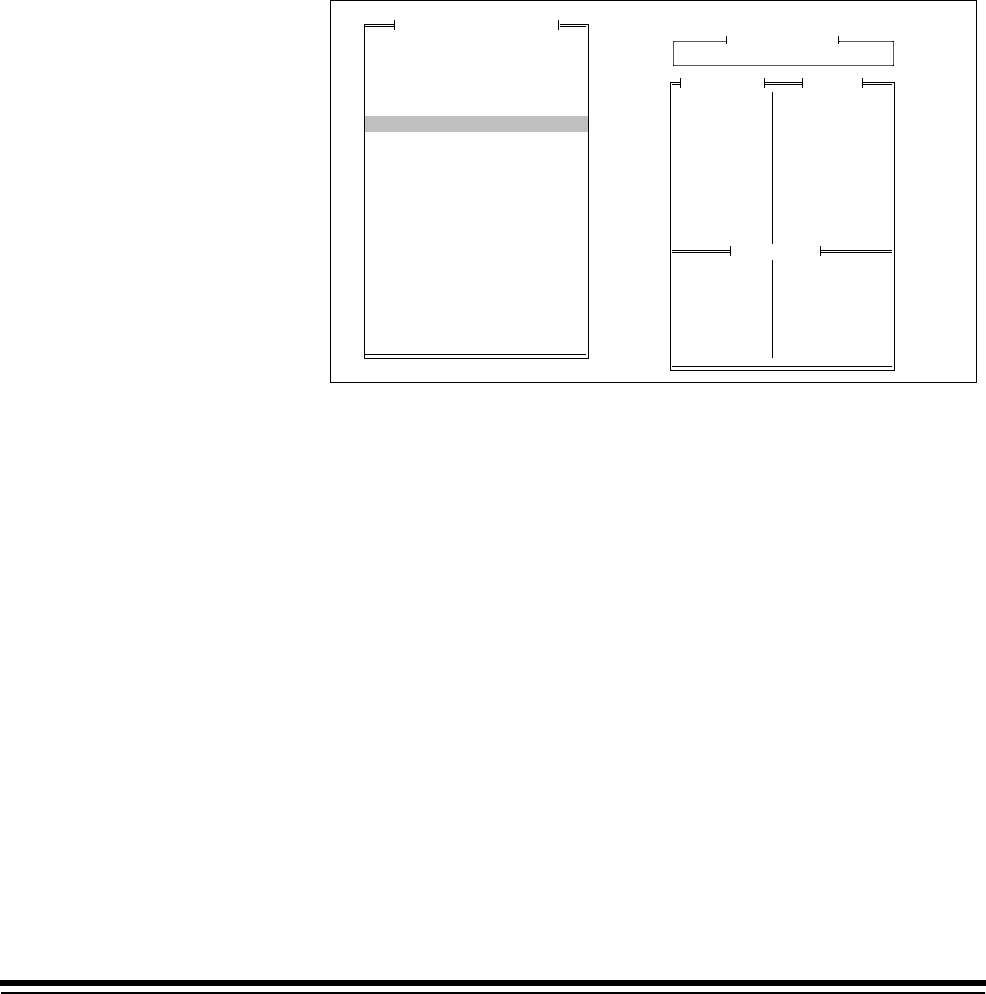
A-61097 May 1997 2-19
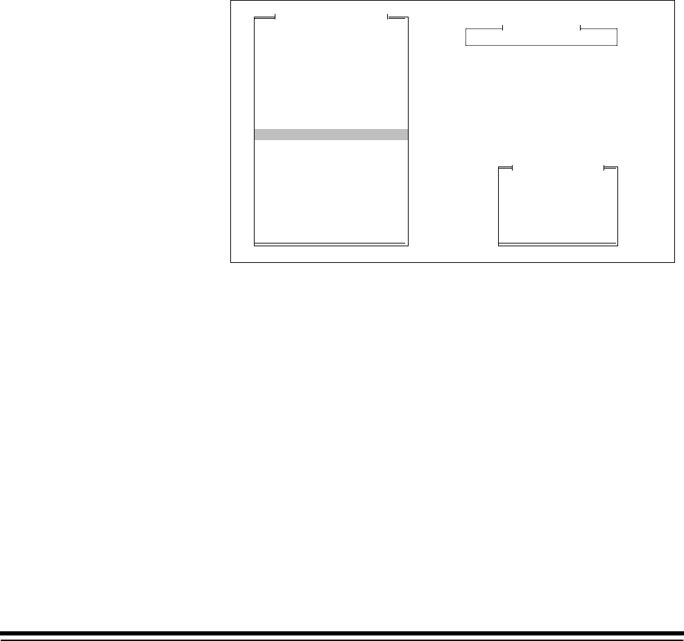
Dotted line = Starting print position (distance from the leading edge of the document).
Line 1
Line 2
Line 3
Line 4
Line 5
Line 6
Line 7
Line 8
Line 9
Line 10
Line 11
Line 12
Line 13
Line 14
Line 15
Line 16
Line 17
Line 18
Line 19
Line 20
Line 21
Line 22
Line 23
Line 24
Line 25
Line 26
Line 27
Line 28
Line 29
Line 30
Line 31
Line 32
Line 33
Line 34
Line 35
Line 36
Line 37
Line 38
(5.5 lines per inch)
Vertical placement on the document is dependent upon the position of the
Document Printer 12 in the transport plate.
2-20 A-61097 May 1997
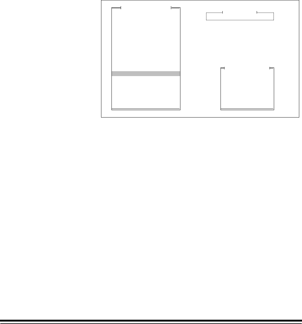
Dotted line = Starting print position (distance from the leading edge of the document).
Line 1
Line 2
Line 3
Line 4
Line 5
Line 6
Line 7
Line 8
Line 9
Line 10
Line 11
Line 12
Line 13
Line 14
Line 15
Line 16
Line 17
Line 18
Line 19
Line 20
Line 21
Line 22
Line 23
Line 24
Line 25
Line 26
(4 lines per inch)
Vertical placement on the document is dependent upon the position of the
Document Printer 12 in the transport plate.
A-61097 May 1997 2-21
Fixed Field Delimiter
This option defines the fixed field delimiter used in the Image Address
Display. The default is a Period (.).
NOTE: The Fixed Field Delimiter doesn’t appear on the display; it
appears when printing the Image Address.
❏Microimager 70 ■Microimager 70/AFM ■Scanner 900
■Scanner 923 ■Scanner/Microimager 990 ■Scanner 9500
1. Select Fixed Field Delimiter.
2. Select the desired Fixed Field delimiter.
NOTE: In order to print the Fixed Field Delimiter using Document Printer
12, the Image Address must be defined as having eleven (11)
digits maximum.
Display Machine Accessories
Machine ID Number
Display Language
Measurement System
Programmable Function Keys
Date Format
Time Format
Alarm Tone
Doc Printer/Film Writer Msg
DP-12 Print Template
Fixed Field Delimiter
Set System Clock
Version Numbers
User COIN Port Protocol
Custom Check Digit
OI Hardware Character Set
Save Configuration to PC
Load Configuration from PC
Mode Configuration
End Session
MACHINE STATE
Slash
Dash
Period
Space
Back-Slash
Previous Menu
Fixed Field Delimiter
Mainframe Configuration
("/")
("-")
(".")
(" ")
("\")

2-22 A-61097 May 1997
Set System Clock
This option sets the system clock.
■Microimager 70 ■Microimager 70/AFM ■Scanner 900
■Scanner 923 ■Scanner/Microimager 990 ■Scanner 9500
1. Select Set System Clock.
Display Machine Accessories
Machine ID Number
Display Language
Measurement System
Programmable Function Keys
Date Format
Time Format
Alarm Tone
Doc Printer/Film Writer Msg
DP-12 Print Template
Fixed Field Delimiter
Set System Clock
Version Numbers
User COIN Port Protocol
Custom Check Digit
OI Hardware Character Set
Save Configuration to PC
Load Configuration from PC
Mode Configuration
End Session
MACHINE STATE
Mainframe Configuration
Set Month
Set Day
Set Year
Set Hour
Set Minute
Terminal Time
Previous Menu
Set System Clock
Date
11-10-1992
Time
01:40
If the computer being used to program the unit has its own internal clock:
2. Select Terminal Time to download the time and date.
MACHINE STATE
Mainframe Configuration
Set Month
Set Day
Set Year
Set Hour
Set Minute
Terminal Time
Previous Menu
Set System Clock
Date
11-10-1992
Time
01:40
Yes No
Display Machine Accessories
Machine ID Number
Display Language
Measurement System
Programmable Function Keys
Date Format
Time Format
Alarm Tone
Doc Printer/Film Writer Msg
DP-12 Print Template
Fixed Field Delimiter
Set System Clock
Version Numbers
User COIN Port Protocol
Custom Check Digit
OI Hardware Character Set
Save Configuration to PC
Load Configuration from PC
Mode Configuration
End Session

A-61097 May 1997 2-23
3. Verify that the terminal time should be downloaded by selecting Yes;
or to cancel the download, select No.
If the computer being used to program the unit does not have an internal
clock or the internal clock is not accurate:
4. Select the time or date component you wish to define (month, day,
year, hour or minute).
Display Machine Accessories
Machine ID Number
Display Language
Measurement System
Programmable Function Keys
Date Format
Time Format
Alarm Tone
Doc Printer/Film Writer Msg
DP-12 Print Template
Fixed Field Delimiter
Set System Clock
Version Numbers
User COIN Port Protocol
Custom Check Digit
OI Hardware Character Set
Save Configuration to PC
Load Configuration from PC
Mode Configuration
End Session
MACHINE STATE
Mainframe Configuration
Set Month
Set Day
Set Year
Set Hour
Set Minute
Terminal Time
Previous Menu
Set System Clock
Date
11-10-1992
Time
01:40
Enter a new month below
11
To Change: Enter Value
To Retain: Press Enter
5. Enter a value for the component selected.

2-24 A-61097 May 1997
Version Numbers
This option displays the current software version(s) installed in the
machine and is for viewing only; no selections or entries are made.
■Microimager 70 ■Microimager 70/AFM ■Scanner 900
■Scanner 923 ■Scanner/Microimager 990 ■Scanner 9500
1. Select Version Numbers.
Display Machine Accessories
Machine ID Number
Display Language
Measurement System
Programmable Function Keys
Date Format
Time Format
Alarm Tone
Doc Printer/Film Writer Msg
DP-12 Print Template
Fixed Field Delimiter
Set System Clock
Version Numbers
User COIN Port Protocol
Custom Check Digit
OI Hardware Character Set
Save Configuration to PC
Load Configuration from PC
Mode Configuration
End Session
MACHINE STATE
Mainframe Configuration
AEC
BARCO
FDS
MCP
OI
PATCH
DPC
OCR
SCSI
U CAS
L CAS
LAPTOP
Version #
: 03.36
: 04.05
: 07.02
: 08.08
: 07.01
: 02.11
: 07.04
: 00.00
: 08.06
: 01.00
: 00.00
: 02.35
2. Press Return/Enter to close the Version # window.
NOTE: The following options are not available on scanners 900, 923, and
9500:
AEC: n/a
FDS: n/a
U CAS: n/a
L CAS: n/a
NOTE: On the Microimager 70:
SCSI: n/a
OCR: n/a
NOTE: On the Microimager 70/AFM:
SCSI: n/a
A-61097 May 1997 2-25
User COIN Port Protocol
This option enables or disables the user COIN port for communication
protocols associated with OCR data, Document Scanning Array / Bar
Code Reader, or Customer specified. The default value is Disabled.
■Microimager 70 ■Microimager 70/AFM ■Scanner 900
■Scanner 923 ■Scanner/Microimager 990 ■Scanner 9500
1. Select User COIN Port Protocol.
2. Select the desired User COIN Port protocol.
Display Machine Accessories
Machine ID Number
Display Language
Measurement System
Programmable Function Keys
Date Format
Time Format
Alarm Tone
Doc Printer/Film Writer Msg
DP-12 Print Template
Fixed Field Delimiter
Set System Clock
Version Numbers
User COIN Port Protocol
Custom Check Digit
OI Hardware Character Set
Save Configuration to PC
Load Configuration from PC
Mode Configuration
End Session
MACHINE STATE
Mainframe Configuration
Disabled
Bar Code/KDIS Protocol
User-Defined KDIS Format
OCR Data Protocol
User-Defined Protocol
Previous Menu
User COIN Port Protocol
Bar Code/KDIS Protocol should be selected when using the Bar Code
Accessory. This communications protocol does not call for handshaking
between the Microimager 70, Scanner 900, Scanner 923, Scanner 9500,
or Scanner/Microimager 990 and the host system.
OCR Data Protocol should be selected when using the OCR accessory.
This communications protocol calls for handshaking between the
Microimager 70, Scanner 900, Scanner 923, or Scanner/Microimager 990
and the host system.
2-26 A-61097 May 1997
If User-Defined Protocol is selected, the following window will be
displayed:
Baud Rate
Parity Bit
Char. Length
Handshaking
Update FF
Previous Menu
User COIN Port Config
Display Machine Accessories
Machine ID Number
Display Language
Measurement System
Programmable Function Keys
Date Format
Time Format
Alarm Tone
Doc Printer/Film Writer Msg
DP-12 Print Template
Fixed Field Delimiter
Set System Clock
Version Numbers
User COIN Port Protocol
Custom Check Digit
OI Hardware Character Set
Save Configuration to PC
Load Configuration from PC
Mode Configuration
End Session
MACHINE STATE
Mainframe Configuration
Disabled
Bar Code/KDIS Protocol
User-Defined KDIS Format
OCR Data Protocol
User-Defined Protocol
Previous Menu
User COIN Port Protocol
9600
None
8 Bits
None
Update
Enter the required configuration information by selecting each of the
configuration options in turn and entering the appropriate values:
3. Select Baud Rate.
4. Select the desired baud rate.
Baud Rate
Parity Bit
Char. Length
Handshaking
Update FF
Previous Menu
User COIN Port Config
Display Machine Accessories
Machine ID Number
Display Language
Measurement System
Programmable Function Keys
Date Format
Time Format
Alarm Tone
Doc Printer/Film Writer Msg
DP-12 Print Template
Fixed Field Delimiter
Set System Clock
Version Numbers
User COIN Port Protocol
Custom Check Digit
OI Hardware Character Set
Save Configuration to PC
Load Configuration from PC
Mode Configuration
End Session
MACHINE STATE
Mainframe Configuration
300
600
1200
2400
4800
9600
19.2
Previous Menu
Baud Rate
9600
None
8 Bits
None
Update
A-61097 May 1997 2-27
5. Select Parity Bit.
6. Select the desired parity.
Baud Rate
Parity Bit
Char. Length
Handshaking
Update FF
Previous Menu
User COIN Port Config
Display Machine Accessories
Machine ID Number
Display Language
Measurement System
Programmable Function Keys
Date Format
Time Format
Alarm Tone
Doc Printer/Film Writer Msg
DP-12 Print Template
Fixed Field Delimiter
Set System Clock
Version Numbers
User COIN Port Protocol
Custom Check Digit
OI Hardware Character Set
Save Configuration to PC
Load Configuration from PC
Mode Configuration
End Session
MACHINE STATE
Mainframe Configuration
No Parity
Odd Parity
Even Parity
Previous Menu
Parity
9600
None
8 Bits
None
Update
7. Select Char. Length.
8. Select the desired character length.
Char Length
Baud Rate
Parity Bit
Char. Length
Handshaking
Update FF
Previous Menu
User COIN Port Config
Display Machine Accessories
Machine ID Number
Display Language
Measurement System
Programmable Function Keys
Date Format
Time Format
Alarm Tone
Doc Printer/Film Writer Msg
DP-12 Print Template
Fixed Field Delimiter
Set System Clock
Version Numbers
User COIN Port Protocol
Custom Check Digit
OI Hardware Character Set
Save Configuration to PC
Load Configuration from PC
Mode Configuration
End Session
MACHINE STATE
Mainframe Configuration
9600
None
8 Bits
None
Update
7 Bits
8 Bits
Previous Menu

2-28 A-61097 May 1997
9. Select Handshaking.
10. Select the handshaking protocol.
Handshaking
Baud Rate
Parity Bit
Char. Length
Handshaking
Update FF
Previous Menu
User COIN Port Config
Display Machine Accessories
Machine ID Number
Display Language
Measurement System
Programmable Function Keys
Date Format
Time Format
Alarm Tone
Doc Printer/Film Writer Msg
DP-12 Print Template
Fixed Field Delimiter
Set System Clock
Version Numbers
User COIN Port Protocol
Custom Check Digit
OI Hardware Character Set
Save Configuration to PC
Load Configuration from PC
Mode Configuration
End Session
MACHINE STATE
Mainframe Configuration
9600
None
8 Bits
None
Update
None
CTS/RTS
Previous Menu
11. Select Update F.F.
12. Select Fixed Field option.
Don’t Update FF
Update Fixed Field
Previous Menu
Update Fixed Field
13. Select Previous Menu to close the User COIN Port Config window.

A-61097 May 1997 2-29
Custom Check Digit
This option determines the check digit algorithm to be used when a
custom check digit is calculated.
NOTE: If a standard check digit algorithm is desired, specify the desired
algorithm during Image Address print definitions within each mode
setup.
❏Microimager 70 ■Microimager 70/AFM ■Scanner 900
■Scanner 923 ■Scanner/Microimager 990 ■Scanner 9500
1. Select Custom Check Digit.
Display Machine Accessories
Machine ID Number
Display Language
Measurement System
Programmable Function Keys
Date Format
Time Format
Alarm Tone
Doc Printer/Film Writer Msg
DP-12 Print Template
Fixed Field Delimiter
Set System Clock
Version Numbers
User COIN Port Protocol
Custom Check Digit
OI Hardware Character Set
Save Configuration to PC
Load Configuration from PC
Mode Configuration
End Session
MACHINE STATE
Mainframe Configuration
The check digit is used to ensure the integrity of the Image Address.
All parameters in the algorithm are user-definable, offering a high degree
of flexibility.
During filming and/or scanning, the microfilmer or scanner assigns each
document an Image Address. The Image Address is used to compute the
check digit. The check digit then becomes the rightmost digit of the Image
Address (therefore, the Image Address must be defined as having a
maximum of eleven (11) characters).
NOTE: Because only one position is reserved, the check digit defaults to
zero when the following conditions occur:
• The Lookup Table is used and the check digit is greater than
ten (10).
• The Lookup Table is not used and the check digit is greater
than nine (9).
2-30 A-61097 May 1997
Check Digit = Constant 2 -
Custom Check Digit Formula
[Sum of IA Digits * Attributes] + Constant 1
Divisor
Custom Check Digit Definition
Current ValueParameter
46231546231
00
00
07
Right
No
abcdefghijk
Attributes
Constant 1
Constant 2
Divisor
Left/Right
LUT Status
Lookup Table
Help
Previous Menu
The parameters displayed in the Custom Check Digit Definition window
must be defined.
The following section contains an explanation of each field:
• Constant 2—A constant value in the range 0 through 99.
• IA Digits—The digits comprising the Image Address. The Image
Address may contain a fixed field as many as three level fields. The
Image Address cannot exceed 11 data characters when accompanied
by a check digit; the check digit occupies one character position.
• Attributes—These are position weights for digits in the Image Address.
A zero-value attribute causes the associated Image Address digit to be
excluded from the check digit calculation. Each digit in the Image
Address is multiplied by its attribute and summed. For example, if the
Image Address is 1202.14.342.12 and you wish to calculate a check
digit that excludes the fixed field (1202), the attributes (using Table 1)
would be 00001546231.
Table 1: Default Image Address Attributes
C10 c9 c8 c7 c6 c5 c4 c3 c2 c1 c0
46231546231
NOTE: The “c” in Table 1 refers to the character position.

A-61097 May 1997 2-31
• Constant1—A constant value in the range 0 through 99.
• Divisor—a constant value between 0 and 99.
NOTE: The divisor is not used if value specified is zero (0).
In addition to the parameters in the equation, there are other user defined
parameters which affect check digit processing:
• Left/Right specifier (also referred to as L/R of Decimal)—Indicates the
location of the check digit in relation to the decimal point in the
calculation results. This rule is applied to the ([Sum of IA Digits *
Attributes] = Constant 1)/Divisor portion of the calculation. If Left is
specified, the check digit is the digit immediately to the left of the
decimal point; if Right is specified, the digit immediately to the right of
the decimal point is the check digit. For example: If the calculation
produces the number 123.45 and Right is the designated Left/Right
parameter, then 4 is used.
The following are exceptions to the Left/Right specifier rule:
— If Constant2 is not zero, and the Left/Right specifier is Left, the
check digit equals the difference between Constant2 and the first
digit to the left of the decimal point. If Constant2 is zero, the first
digit to the left of the decimal point becomes the check digit.
— If Constant2 is not zero and the Left/Right specifier is Right, the
check digit equals the difference between Constant2 and the first
digit to the right of the decimal. If Constant2 is zero, the first digit to
the right of the decimal point becomes the check digit.
• LUT (Lookup Table) Status—If Yes, the final check digit calculated is
used as an index into a lookup table. If No is specified, the lookup table
is ignored.
• Lookup table—A table of check digit values (refer to Table 2).
Table 2: Default Lookup Table values
C10 c9 c8 c7 c6 c5 c4 c3 c2 c1 c0
a b c d e f g h i j k

2-32 A-61097 May 1997
Sample check digit calculation #1
Assume the following:
Image Address = 123.45.678.912
Attributes = 46231546231
Constant 1 = 7
Constant 2 = 10
Divisor = 11
Left/Right = Right
LUT Status = No/off
Lookup Table = abcdefghijk
Then the check digit calculation would be:
1. Set up the equation:
Check Digit = 10 - [Calculation 1] + 7
Calculation 1 = (2 x 1) + (1 x 3) + (9 x 2) + (8 x 6) + (7 x 4) + (6 x 5) +
(5 x 1) + (4 x 3) + (3 x 2) + (2 x 6) + (1 x 4)
2. Calculate the value of the fraction:
168 + 7 = 15.91
3. Apply the Left/Right parameter:
15.91 = 5 if Left is specified
15.91 = 9 if Right is specified
In this example, 9 isused.
4. Complete the calculation:
10 - 9 = 1
In this example, 1 is the check digit. The Image Address printed by the
Document Printer would be: 123.45.678.9121
NOTE: Because only one position is reserved, the check digit defaults to
zero when the following conditions occur:
• The Lookup Table is used and the check digit is greater than
ten (10).
• The Lookup Table is not used and the check digit is greater
than nine (9).

A-61097 May 1997 2-33
Sample check digit calculation #2
Assume the following:
Image Address = 123.45.678.912
Attributes = 46231546231
Constant 1 = 7
Constant 2 = 10
Divisor = 11
Left/Right = Right
LUT Status = Yes/on
Lookup Table = abcdefghijk
Then the check digit calculation would be:
1. Set up the equation:
Check Digit = 10 - [Calculation 1] + 7
Calculation 1 = (2 x 1) + (1 x 3) + (9 x 2) + (8 x 6) + (7 x 4) + (6 x 5) +
(5 x 1) + (4 x 3) + (3 x 2) + (2 x 6) + (1 x 4)
2. Calculate the value of the fraction:
168 + 7 = 15.91
3. Apply the Left/Right parameter:
15.91 = 5 if Left is specified
15.91 = 9 if Right is specified
In this example, 9 is used.
4. Complete the calculation:
10 - 9 = 1
5. Apply the Lookup Table values:
1 cross references to B
In this example, 1 is the check digit. The Image Address printed by the
Document Printer would be: 123.45.678.912B.
NOTE: Because only one position is reserved, the check digit defaults to
zero when the following conditions occur:
• The Lookup Table is used and the check digit is greater than
ten (10).
• The Lookup Table is not used and the check digit is greater
than nine (9).

2-34 A-61097 May 1997
To program a custom check digit algorithm, use the following sequence of
steps:
1. Select the Attributes parameter for definition.
2. Enter the desired attribute values.
Enter attribute values.
Req’d entry 11 digits.
46231546231
To Change: Enter Value
To Retain: Press Enter
Check Digit = Constant 2 - [Sum of IA Digits * Attributes] + Constant 1
Divisor
Current ValueParameter
46231546231
00
00
07
Right
No
abcdefghijk
Attributes
Constant 1
Constant 2
Divisor
Left/Right
LUT Status
Lookup Table
Help
Previous Menu
Custom Check Digit Formula
Custom Check Digit Definition
3. Select the Constant1 parameter for definition.
4. Enter a value between 00 – 99.
Enter constant #1.
Req’d entry 2 digits.
00
To Change: Enter Value
To Retain: Press Enter
Check Digit = Constant 2 - [Sum of IA Digits * Attributes] + Constant 1
Divisor
Current ValueParameter
46231546231
00
00
07
Right
No
abcdefghijk
Attributes
Constant 1
Constant 2
Divisor
Left/Right
LUT Status
Lookup Table
Help
Previous Menu
Custom Check Digit Formula
Custom Check Digit Definition

A-61097 May 1997 2-35
5. Select the Constant2 parameter for definition.
6. Enter a value between 00 – 99.
Enter constant #2.
Req’d entry 2 digits.
00
To Change: Enter Value
To Retain: Press Enter
Check Digit = Constant 2 - [Sum of IA Digits * Attributes] + Constant 1
Divisor
Current ValueParameter
46231546231
00
00
07
Right
No
abcdefghijk
Attributes
Constant 1
Constant 2
Divisor
Left/Right
LUT Status
Lookup Table
Help
Previous Menu
Custom Check Digit Formula
Custom Check Digit Definition
7. Select the Divisor parameter for definition.
8. Enter a value between 00 – 99.
Enter divisor.
Req’d entry 2 digits.
07
To Change: Enter Value
To Retain: Press Enter
Check Digit = Constant 2 - [Sum of IA Digits * Attributes] + Constant 1
Divisor
Current ValueParameter
46231546231
00
00
07
Right
No
abcdefghijk
Attributes
Constant 1
Constant 2
Divisor
Left/Right
LUT Status
Lookup Table
Help
Previous Menu
Custom Check Digit Formula
Custom Check Digit Definition

2-36 A-61097 May 1997
9. Select the Left/Right parameter for definition.
10. Select the digit to be used during calculation of the check digit.
Check Digit = Constant 2 - [Sum of IA Digits * Attributes] + Constant 1
Divisor
Current ValueParameter
46231546231
00
00
07
Right
No
abcdefghijk
Attributes
Constant 1
Constant 2
Divisor
Left/Right
LUT Status
Lookup Table
Help
Previous Menu
Left of Decimal Pt
Right of Decimal Pt
Previous Menu
Start Formula at:
Custom Check Digit Formula
Custom Check Digit Definition
11. Select the LUT Status parameter for definition.
12. Select the desired option depending upon whether or not a lookup
table will be used.
Check Digit = Constant 2 -
Custom Check Digit Formula
[Sum of IA Digits * Attributes] + Constant 1
Divisor
Current ValueParameter
46231546231
00
00
07
Right
No
abcdefghijk
Attributes
Constant 1
Constant 2
Divisor
Left/Right
LUT Status
Lookup Table
Help
Previous Menu
Don’t use Lookup Table
Use Lookup Table
Previous Menu
Lookup Table Status
Custom Check Digit Formula
Custom Check Digit Definition
A-61097 May 1997 2-37
13. Select the Lookup Table parameter for definition.
14. Enter the desired lookup table values.
Enter lookup table.
Req’d entry 11 digits.
abcdefghijk
To Change: Enter Value
To Retain: Press Enter
Check Digit = Constant 2 - [Sum of IA Digits * Attributes] + Constant 1
Divisor
Current ValueParameter
46231546231
00
00
07
Right
No
abcdefghijk
Attributes
Constant 1
Constant 2
Divisor
Left/Right
LUT Status
Lookup Table
Help
Previous Menu
Custom Check Digit Formula
Custom Check Digit Definition
Custom Check Digit Configuration Help
Parameters Explanation
Attributes These are position weights for digit in the IA. A zero-
value attribute causes the associated IA digit to be
excluded from the check digit calculation. Each digit in
the IA is multiplied by its attribute and summed.
Constant 1 A constant in the range 00–99.
Constant 2 A constant in the range 00–99.
Divisor A constant in the range 00–99. Not used if value is
zero.
Left/Right Indicates the location of the check digit in relation to
the decimal point in the calculation results. If left is
specified, the check digit is immediately to the left of
the decimal point and vice versa.
LUT Status If Yes, the final check digit calculated is used as an
index into a lookup table. If No, the lookup table is
ignored.
Lookup Table A table of check digit values.
2-38 A-61097 May 1997
OI Hardware Character Set
This option defines non-English character sets which may be used by the
Operator Interface, Document Printers and the Film Writer. English
characters are contained in both sets. The default OI character set is
Anglo/Japanese.
❏Microimager 70 ■Microimager 70/AFM ■Scanner 900
■Scanner 923 ■Scanner/Microimager 990 ■Scanner 9500
1. Select OI Hardware Character Set.
2. Enter the desired printer font option.
NOTE: The proper hardware display module must be installed.
Display Machine Accessories
Machine ID Number
Display Language
Measurement System
Programmable Function Keys
Date Format
Time Format
Alarm Tone
Doc Printer/Film Writer Msg
DP-12 Print Template
Fixed Field Delimiter
Set System Clock
Version Numbers
User COIN Port Protocol
Custom Check Digit
OI Hardware Character Set
Save Configuration to PC
Load Configuration from PC
Mode Configuration
End Session
MACHINE STATE
Anglo/Japanese
Anglo/European
Previous Menu
Printer Font
Mainframe Configuration
Instructions
1. Check the character display on
the bottom line of the OI.
2. Select the character set based
on the character.
Chracter Set
– Anglo/Japanese
ë Anglo/European
A-61097 May 1997 2-39
Save Configuration to PC
This option is used to download a configuration file from the scanner or
microfilmer onto diskette. This is useful in creating configuration files
which may be transported to other units (see the Load Config from PC
option). This is also used to create backup files. This option should be
performed any time an installation or setup change is completed.
■Microimager 70 ■Microimager 70/AFM ■Scanner 900
■Scanner 923 ■Scanner/Microimager 990 ■Scanner 9500
1. Select Save Configuration to PC.
2. Enter a file name (up to 8 characters long – no special characters
allowed).
Display Machine Accessories
Machine ID Number
Display Language
Measurement System
Programmable Function Keys
Date Format
Time Format
Alarm Tone
Doc Printer/Film Writer Msg
DP-12 Print Template
Fixed Field Delimiter
Set System Clock
Version Numbers
User COIN Port Protocol
Custom Check Digit
OI Hardware Character Set
Save Configuration to PC
Load Configuration from PC
Mode Configuration
End Session
MACHINE STATE
Mainframe Configuration
3. Select Complete Configuration.
Please select which machine
variables you wish to load from
IMAGELINK to the Laptop.
Mode Parameters/Templates/
Messages
Complete Configuration

2-40 A-61097 May 1997
Load Configuration from PC
This option is used to upload a configuration file from diskette to the
scanner or microfilmer.
■Microimager 70 ■Microimager 70/AFM ■Scanner 900
■Scanner 923 ■Scanner/Microimager 990 ■Scanner 9500
1. Select Load Configuration from PC.
2. Enter a file name to upload.
Display Machine Accessories
Machine ID Number
Display Language
Measurement System
Programmable Function Keys
Date Format
Time Format
Alarm Tone
Doc Printer/Film Writer Msg
DP-12 Print Template
Fixed Field Delimiter
Set System Clock
Version Numbers
User COIN Port Protocol
Custom Check Digit
OI Hardware Character Set
Save Configuration to PC
Load Configuration from PC
Mode Configuration
End Session
MACHINE STATE
Mainframe Configuration

A-61097 May 1997 3-1
3 Selecting the Mode Configuration Window
This section lists the Mode Definitions for the Scanner/Microimager.
Follow these steps to select the Mode Definition screen.
Display Machine Accessories
Machine ID Number
Display Language
Measurement System
Programmable Function Keys
Date Format
Time Format
Alarm Tone
Doc Printer/Film Writer Msg
DP-12 Print Template
Fixed Field Delimiter
Set System Clock
Version Numbers
User COIN Port Protocol
Custom Check Digit
OI Hardware Character Set
Save Configuration to PC
Load Configuration from PC
Mode Configuration
End Session
MACHINE STATE
Mainframe Configuration
1. Select Mode Configuration.
The following window will be displayed:
Define Mode 1
Define Mode 2
Define Mode 3
Define Mode 4
Define Mode 5
Define Mode 6
Define Mode 7
Define Mode 8
Define Mode 9
Define Mode 10
Define Mode 11
Define Mode 12
Define Mode 13
Define Mode 14
Define Mode 15
Define Mode 16
Define Mode 17
Define Mode 18
Mode Configuration
Mode to Mode Copy
End Session
Previous Menu
3-2 A-61097 May 1997
2. Select a mode to be defined.
The Mode Configuration window will be displayed, with the Mode
Number you selected for definition displayed at the top.
MODE 10
3 Lvl
Supprs
4233
2112
None
Auto
Duplex
?????
1 Roll
Comic
Off
Off
Off
Xport
Off
Undef
Undef
Off
Off
Off
Lvl 2
On
N N N
Off
On
Disply
Off
Off
Off
Off
No Sav
F
Mode Name
Index Format
IA Display Format
IA Field Widths
Level Rules
Batching
AEC Mode
Film Mode
Reduction Ratio
# of Cassettes
Film Writer
Image Mgmt Code
Length Monitor
Skew Monitor
Check Stacker
Endorser
Not Used
Ftswitch Pressed
Ftswitch Released
Ftswitch Cnf Tone
Patch Reader 1
Patch Reader 2
Patch Definition
Bar Code
Confirmation Tone
OCR Status
COIN User Channel
Printer Control
Primary DP-1
Secondary DP-1
Doc. Printer 12
Document Sorter
Mode Overrides
Film Definition
Mode Configuration
Don't Save & End Session
End Configuration
Save & End Session
Previous Menu
Mode Number: 10 Mode Name: MODE10
This window provides access to all of the mode definition parameters.
NOTE: The following options are not available on scanners 900, 923, and
9500:
AEC Mode
Film Mode
Reduction Ratio
# of Cassettes
Film Writer
Image Mgmt Code
Film Definition = NoF

A-61097 May 1997 3-3
Mode Definitions
The following section lists the items on the Mode Configuration Menu that
may be selected for definition. Unavailable machine types are indicated by
hollow boxes.
Mode Name
This option defines the mode name.
❏Microimager 70 ■Microimager 70/AFM ■Scanner 900
■Scanner 923 ■Scanner/Microimager 990 ■Scanner 9500
1. Select Mode Name.
MODE 10
3 Lvl
Supprs
4233
2112
None
Auto
Duplex
?????
1 Roll
Comic
Off
Off
Off
Xport
Off
Undef
Undef
Off
Off
Off
Lvl 2
Off
N N N
Off
On
Disply
Off
Off
Off
Off
No Sav
F
Mode Name
Index Format
IA Display Format
IA Field Widths
Level Rules
Batching
AEC Mode
Film Mode
Reduction Ratio
# of Cassettes
Film Writer
Image Mgmt Code
Length Monitor
Skew Monitor
Check Stacker
Endorser
Not Used
Ftswitch Pressed
Ftswitch Released
Ftswitch Cnf Tone
Patch Reader 1
Patch Reader 2
Patch Definition
Bar Code
Confirmation Tone
OCR Status
COIN User Channel
Printer Control
Primary DP-1
Secondary DP-1
Doc. Printer 12
Document Sorter
Mode Overrides
Film Definition
Mode Configuration
Don't Save & End Session
End Configuration
Save & End Session
Previous Menu
Mode Number: 10 Mode Name: MODE10
Enter Mode Name
MODE10
2. Enter a ten (10) character (maximum) alphanumeric name.
3-4 A-61097 May 1997
Index Format
This mode defines the index format used by the application mode. Refer
to Description 3: Index Formats for a description of the index formats.
■Microimager 70 ■Microimager 70/AFM ■Scanner 900
■Scanner 923 ■Scanner/Microimager 990 ■Scanner 9500
When using a Microimager 70 without the Advanced Function Module
installed, only the index format for Mode 8 and Mode 9 may be defined;
the index format is predefined and unalterable in Mode 1 through Mode 7.
The predefined values are:
• Mode 1—Single Level
• Mode 2—Two Level Offset
• Mode 3—Two Level
• Mode 4—Three Level Offset
• Mode 5—Three Level
• Mode 6—Two Level
• Mode 7—Two Level Offset
When using a Microimager with the Advanced Function Module installed,
Scanner 900, Scanner 923, Scanner 9500, or Scanner/Microimager 990,
the index format for all modes may be defined.
1. Select Index Format.
Mode Configuration
Don't Save & End Session
End Configuration
Save & End Session
Previous Menu
Mode Number: 10 Mode Name: MODE10
Single Level
Two Level
Three Level
Two Level Offset
Three Level Offset
Previous Menu
Index Format
MODE 10
3 Lvl
Supprs
4233
2112
None
Auto
Duplex
?????
1 Roll
Comic
Off
Off
Off
Xport
Off
Undef
Undef
Off
Off
Off
Lvl 2
Off
N N N
Off
On
Disply
Off
Off
Off
Off
No Sav
F
Mode Name
Index Format
IA Display Format
IA Field Widths
Level Rules
Batching
AEC Mode
Film Mode
Reduction Ratio
# of Cassettes
Film Writer
Image Mgmt Code
Length Monitor
Skew Monitor
Check Stacker
Endorser
Not Used
Ftswitch Pressed
Ftswitch Released
Ftswitch Cnf Tone
Patch Reader 1
Patch Reader 2
Patch Definition
Bar Code
Confirmation Tone
OCR Status
COIN User Channel
Printer Control
Primary DP-1
Secondary DP-1
Doc. Printer 12
Document Sorter
Mode Overrides
Film Definition
2. Select the desired index format option.
NOTE: If you intend to link the current mode with another mode, the index
format chosen for both modes must be the same.
A-61097 May 1997 3-5
Description 3: Index Formats
There are five Index Format options available:
Single Level
IA 1
(Level 1)
IA 2
(Level 1)
IA 3
(Level 1)
IA 4
(Level 1)
Whenever a small image mark is placed next to a document and/or a document is assigned Level 1, the Image
Address field associated with Level 1 (Field A) is incremented.
Two Level
IA 1.0 IA 1.1 IA 1.2 IA 2.0
(Level 2) (Level 1) (Level 1) (Level 2)
Whenever a medium image mark is placed next to a document and/or the document is assigned Level 2, the
Image Address field associated with Level 2 (Field B) is incremented and the field associated with Level 1
(Field A) is set to zero.
Whenever a small image mark is placed next to a document and/or a document is assigned Level 1, the Image
Address field associated with Level 2 (Field B) is unchanged and the field associated with Level 1 (Field A) is
incremented.
Two Level Offset
IA 1 IA 1 IA 1 IA 2
(Level 2) (Level 1) (Level 1) (Level 2)
Whenever a medium image mark is placed next to a document and/or a document is assigned Level 2, the
Image Address field associated with Level 2 (Field B) is incremented.
Whenever a small image mark is placed next to a document and/or a document is assigned Level 1, the Image
Address is unchanged.
3-6 A-61097 May 1997
Description 3: Index Formats (continued)
Three Level
IA 1.0.0 IA 1.1.0 IA 1.1.1 IA 2.0.0
(Level 3) (Level 2) (Level 1) (Level 3)
Whenever a large image mark is placed next to a document and/or a document is assigned Level 3, the Image
Address field associated with Level 3 (Field C) is incremented and the fields associated with Level 2 (Field B)
and Level 1 (Field A) are set to zero.
Whenever a medium image mark is placed next to a document and/or a document is assigned Level 2, the
Image Address Field associated with Level 3 (Field C) is unchanged, the field associated with Level 2 (Field B)
is incremented, and the field associated with Level 1 (Field A) is set to zero.
Whenever a small image mark is placed next to a document and/or a document is assigned Level 1, the Image
Address fields associated with Level 3 (Field C) and Level 2 (Field B) are unchanged, and the field associated
with Level 1 (Field A) is incremented.
Three Level Offset
IA 1.0 IA 1.1 IA 1.1 IA 2.0
(Level 3) (Level 2) (Level 1) (Level 3)
Whenever a large image mark is placed next to a document and/or a document is assigned Level 3, the Image
Address field associated with Level 3 (Field C) is incremented and the field associated with Level 2 (Field B) is
set to zero.
Whenever a medium image mark is placed next to a document and/or a document is assigned Level 2, the
Image Address field associated with Level 3 (Field C) is unchanged, and the field associated with Level 2 (Field
B) is incremented.
Whenever a small image mark is placed next to a document and/or a document is assigned Level 1, the Image
Address is unchanged.
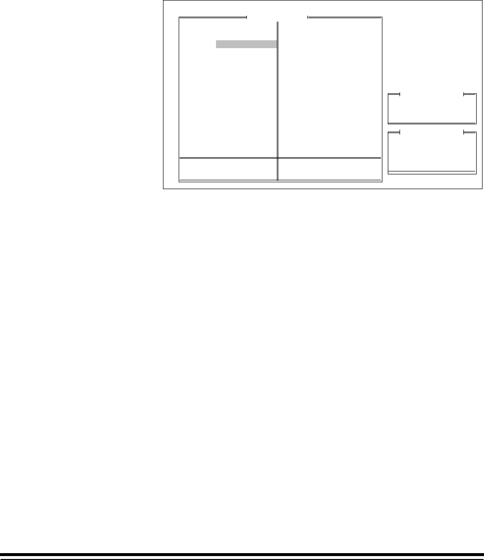
A-61097 May 1997 3-7
Image Address Display Format
This mode defines the format of the Image Address display which appears
on the control panel. The default is Suppress.
❏Microimager 70 ■Microimager 70/AFM ■Scanner 900
■Scanner 923 ■Scanner/Microimager 990 ■Scanner 9500
1. Select IA Display Format.
Mode Configuration
Don't Save & End Session
End Configuration
Save & End Session
Previous Menu
Mode Number: 10 Mode Name: MODE10
Display Leading Zeros
Compress Leading Zeros
Suppress Leading Zeros
Previous Menu
IA Display Format
Display:
Compress:
Suppress:
001.002.003.004
001.2.3.4
001. 002.003.004
Examples of Formats
MODE 10
3 Lvl
Supprs
4233
2112
None
Auto
Duplex
?????
1 Roll
Comic
Off
Off
Off
Xport
Off
Undef
Undef
Off
Off
Off
Lvl 2
Off
N N N
Off
On
Disply
Off
Off
Off
Off
No Sav
F
Mode Name
Index Format
IA Display Format
IA Field Widths
Level Rules
Batching
AEC Mode
Film Mode
Reduction Ratio
# of Cassettes
Film Writer
Image Mgmt Code
Length Monitor
Skew Monitor
Check Stacker
Endorser
Not Used
Ftswitch Pressed
Ftswitch Released
Ftswitch Cnf Tone
Patch Reader 1
Patch Reader 2
Patch Definition
Bar Code
Confirmation Tone
OCR Status
COIN User Channel
Printer Control
Primary DP-1
Secondary DP-1
Doc. Printer 12
Document Sorter
Mode Overrides
Film Definition
2. Select the desired format option.

3-8 A-61097 May 1997
Image Address Field Widths
This mode defines the Image Address field widths.
Refer to Description 4: Image Address Fields for a description of proper
field definitions.
■Microimager 70 ■Microimager 70/AFM ■Scanner 900
■Scanner 923 ■Scanner/Microimager 990 ■Scanner 9500
When using a Microimager 70 without the Advanced Function Module
installed, only the Image Address field widths for Mode 8 and Mode 9 may
be defined; the field widths are predefined and unalterable in Mode 1
through Mode 7. The predefined values are:
• Mode 1 – Fixed Field (6)
Field C – Level 3 (0)
Field B – Level 2 (0)
Field A – Level 1 (6)
• Mode 2 – Fixed Field (6)
Field C – Level 3 (0)
Field B – Level 2 (6)
Field A – Level 1 (0)
• Mode 3 – Fixed Field (6)
Field C – Level 3 (0)
Field B – Level 2 (3)
Field A – Level 1 (3)
• Mode 4 – Fixed Field (6)
Field C – Level 3 (3)
Field B – Level 2 (3)
Field A – Level 1 (0)
• Mode 5 – Fixed Field (4)
Field C – Level 3 (2)
Field B – Level 2 (3)
Field A – Level 1 (3)
• Mode 6 – Fixed Field (6)
Field C – Level 3 (0)
Field B – Level 2 (4)
Field A – Level 1 (2)
• Mode 7 – Fixed Field (6)
Field C – Level 3 (0)
Field B – Level 2 (6)
Field A – Level 1 (0)
When using a Microimager with the Advanced Function Module installed,
Scanner 900, Scanner 923, Scanner 9500, or Scanner/Microimager 990,
the Image Address Field widths for all modes may be defined.
NOTE: A field width definition for all fields (Field A – Level 1, Field B –
Level 2, Field C – Level 3, and Fixed Field ) must be specified.

A-61097 May 1997 3-9
1. Select IA Field Widths.
Mode Configuration
Don't Save & End Session
End Configuration
Save & End Session
Previous Menu
Mode Number: 10 Mode Name: MODE10
Fixed Field
Field A
Field B
Field C
Previous Menu
Field Num
MODE 10
3 Lvl
Supprs
4233
2112
None
Auto
Duplex
?????
1 Roll
Comic
Off
Off
Off
Xport
Off
Undef
Undef
Off
Off
Off
Lvl 2
Off
N N N
Off
On
Disply
Off
Off
Off
Off
No Sav
F
Mode Name
Index Format
IA Display Format
IA Field Widths
Level Rules
Batching
AEC Mode
Film Mode
Reduction Ratio
# of Cassettes
Film Writer
Image Mgmt Code
Length Monitor
Skew Monitor
Check Stacker
Endorser
Not Used
Ftswitch Pressed
Ftswitch Released
Ftswitch Cnf Tone
Patch Reader 1
Patch Reader 2
Patch Definition
Bar Code
Confirmation Tone
OCR Status
COIN User Channel
Printer Control
Primary DP-1
Secondary DP-1
Doc. Printer 12
Document Sorter
Mode Overrides
Film Definition
2. Select the field to be defined.
Mode Configuration
Don't Save & End Session
End Configuration
Save & End Session
Previous Menu
Mode Number: 10 Mode Name: MODE10
Fixed Field
Field A
Field B
Field C
Previous Menu
Field Num
Enter Field Width
0 1 2 3 4 5 6 7 8 9
MODE 10
3 Lvl
Supprs
4233
2112
None
Auto
Duplex
?????
1 Roll
Comic
Off
Off
Off
Xport
Off
Undef
Undef
Off
Off
Off
Lvl 2
Off
N N N
Off
On
Disply
Off
Off
Off
Off
No Sav
F
Mode Name
Index Format
IA Display Format
IA Field Widths
Level Rules
Batching
AEC Mode
Film Mode
Reduction Ratio
# of Cassettes
Film Writer
Image Mgmt Code
Length Monitor
Skew Monitor
Check Stacker
Endorser
Not Used
Ftswitch Pressed
Ftswitch Released
Ftswitch Cnf Tone
Patch Reader 1
Patch Reader 2
Patch Definition
Bar Code
Confirmation Tone
OCR Status
COIN User Channel
Printer Control
Primary DP-1
Secondary DP-1
Doc. Printer 12
Document Sorter
Mode Overrides
Film Definition
3. Select the desired field width for the specified field.
NOTE: If you intend to link the current mode with another mode, the field
width definitions for both modes must be the same.
If you change the field widths a message appears:
To avoid E205 errors at powerup, first save mode programming,
then enter a new IA for mode.
4. Press Enter.

3-10 A-61097 May 1997
Description 4: Image Address Fields
An Image Address is a unique identifier assigned to each individual document by the Microimager 70, Scanner
900, Scanner 923, Scanner 9500, or Scanner/Microimager 990.
An Image Address may contain up to 15 characters, consisting of a maximum of 12 digits
Description 4: Image Address Fields.
An Image Address is a unique identifier assigned to each individual document by the Microimager 70, Scanner
900, Scanner 923, Scanner 9500, or Scanner/Microimager 990.
An Image Address may contain up to 15 characters, consisting of a maximum of 12 digits and a maximum of 3
delimiters.
Four fields must be defined:
Field A represents Level 1. Its value is incremented when a small image mark is placed next to a document
and/or a document is assigned Level 1.
Field B represents Level 2. Its value is incremented when a medium image mark is placed next to a document
and/or a document is assigned Level 2.
Field C represents Level 3. Its value is incremented when a large image mark is placed next to a document
and/or a document is assigned Level 3.
Fixed Field contains fixed information; typically, the date.
Example:
0 3 0 1 . 0 2 . 0 0 1 . 0 0 0 where: Field A contains 000
Field B contains 001
Field C contains 02
Fixed Field contains 0301
The Image Address field lengths are dependent upon the Index Format chosen earlier:
• Single Level
Field A is defined as having a field length greater than zero (1 – 9)
Field B is defined as having a field length of zero (0)
Field C is defined as having a field length of zero (0)
Fixed Field may be defined, if desired (0 – 9)

A-61097 May 1997 3-11
Description 4: Image Address Fields (continued)
• Two Level
Field A is defined as having a field length greater than zero (1 – 9)
Field B is defined as having a field length greater than zero (1 – 9)
Field C is defined as having a field length of zero (0)
Fixed Field may be defined, if desired (0 – 9)
• Two Level Offset
Field A is defined as having a field length of zero (0)
Field B is defined as having a field length greater than zero (1 – 9)
Field C is defined as having a field length of zero (0)
Fixed Field may be defined, if desired (0 – 9)
• Three Level
Field A is defined as having a field length greater than zero (1 –9)
Field B is defined as having a field length greater than zero (1 – 9)
Field C is defined as having a field length greater than zero (1 – 9)
Fixed Field may be defined, if desired (0 – 9)
• Three Level Offset
Field A is defined as having a field length greater than zero (1 –9)
Field B is defined as having a field length greater than zero (1 – 9)
Field C is defined as having a field length greater than zero (1 – 9)
Fixed Field may be defined, if desired (0 – 9)

3-12 A-61097 May 1997
Level Rules
This mode defines the level of a document based upon the level of the
previous document. These definitions are used as defaults when the
document level is not determined by another method (i.e., Footswitch,
P-Key, Level Key, etc.)
■Microimager 70 ■Microimager 70/AFM ■Scanner 900
■Scanner 923 ■Scanner/Microimager 990 ■Scanner 9500
When using a Microimager 70 without the Advanced Function Module
installed, only the level rules for Mode 8 and Mode 9 may be defined; the
level rules are predefined and unalterable in Mode 1 – Mode 7. The
predefined values are:
• Mode 1 – Level 0 followed by Level 1
Level 1 followed by Level 1
Level 2 followed by no level
Level 3 followed by no level
• Mode 2 – Level 0 followed by Level 2
Level 1 followed by Level 1
Level 2 followed by Level 2
Level 3 followed by no level
• Mode 3 – Level 0 followed by Level 2
Level 1 followed by Level 1
Level 2 followed by Level 2
Level 3 followed by no level
• Mode 4 – Level 0 followed by Level 3
Level 1 followed by Level 1
Level 2 followed by Level 2
Level 3 followed by Level 2
• Mode 5 – Level 0 followed by Level 2
Level 1 followed by Level 1
Level 2 followed by Level 1
Level 3 followed by Level 2
• Mode 6 – Level 0 followed by Level 2
Level 1 followed by Level 2
Level 2 followed by no level
Level 3 followed by no level
• Mode 7 – Level 0 followed by Level 2
Level 1 followed by Level 2
Level 2 followed by Level 2
Level 3 followed by no level
When using a Microimager with the Advanced Function Module installed,
Scanner 900, Scanner 923, Scanner 9500, or Scanner/Microimager 990,
the level rules for all modes may be defined.
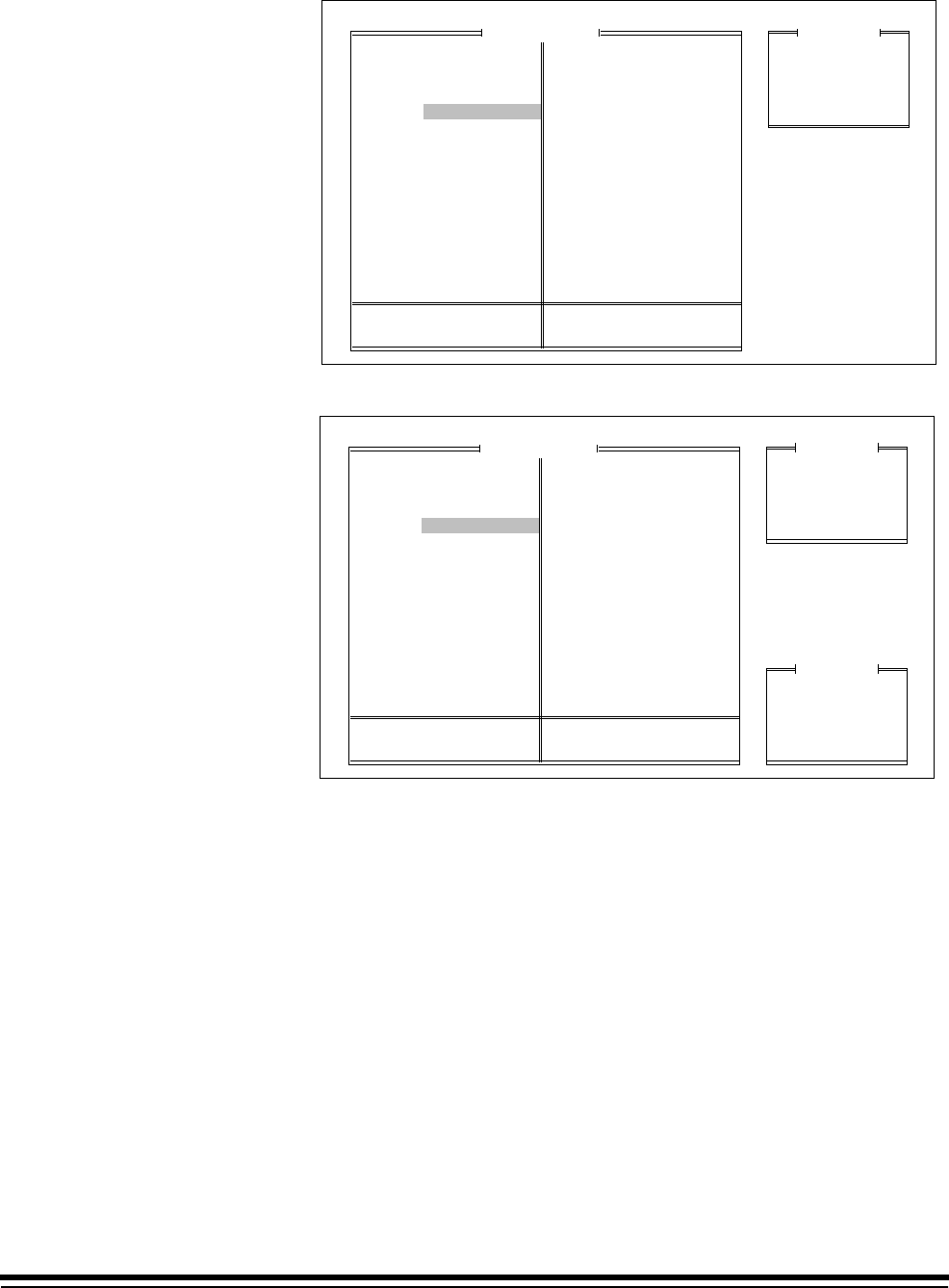
A-61097 May 1997 3-13
1. Select Level Rules.
Mode Configuration
Don't Save & End Session
End Configuration
Save & End Session
Previous Menu
Mode Number: 10 Mode Name: MODE10
Level 0
Level 1
Level 2
Level 3
Previous Menu
Field
MODE 10
3 Lvl
Supprs
4233
2112
None
Auto
Duplex
?????
1 Roll
Comic
Off
Off
Off
Xport
Off
Undef
Undef
Off
Off
Off
Lvl 2
Off
N N N
Off
On
Disply
Off
Off
Off
Off
No Sav
F
Mode Name
Index Format
IA Display Format
IA Field Widths
Level Rules
Batching
AEC Mode
Film Mode
Reduction Ratio
# of Cassettes
Film Writer
Image Mgmt Code
Length Monitor
Skew Monitor
Check Stacker
Endorser
Not Used
Ftswitch Pressed
Ftswitch Released
Ftswitch Cnf Tone
Patch Reader 1
Patch Reader 2
Patch Definition
Bar Code
Confirmation Tone
OCR Status
COIN User Channel
Printer Control
Primary DP-1
Secondary DP-1
Doc. Printer 12
Document Sorter
Mode Overrides
Film Definition
2. Select the level to be assigned a following level.
Mode Configuration
Don't Save & End Session
End Configuration
Save & End Session
Previous Menu
Mode Number: 10 Mode Name: MODE10
Level 0
Level 1
Level 2
Level 3
Previous Menu
Field
Level 0
Level 1
Level 2
Level 3
Previous Menu
Follow Field #
MODE 10
3 Lvl
Supprs
4233
2112
None
Auto
Duplex
?????
1 Roll
Comic
Off
Off
Off
Xport
Off
Undef
Undef
Off
Off
Off
Lvl 2
Off
N N N
Off
On
Disply
Off
Off
Off
Off
No Sav
F
Mode Name
Index Format
IA Display Format
IA Field Widths
Level Rules
Batching
AEC Mode
Film Mode
Reduction Ratio
# of Cassettes
Film Writer
Image Mgmt Code
Length Monitor
Skew Monitor
Check Stacker
Endorser
Not Used
Ftswitch Pressed
Ftswitch Released
Ftswitch Cnf Tone
Patch Reader 1
Patch Reader 2
Patch Definition
Bar Code
Confirmation Tone
OCR Status
COIN User Channel
Printer Control
Primary DP-1
Secondary DP-1
Doc. Printer 12
Document Sorter
Mode Overrides
Film Definition
3. Select the level to follow the specified level.
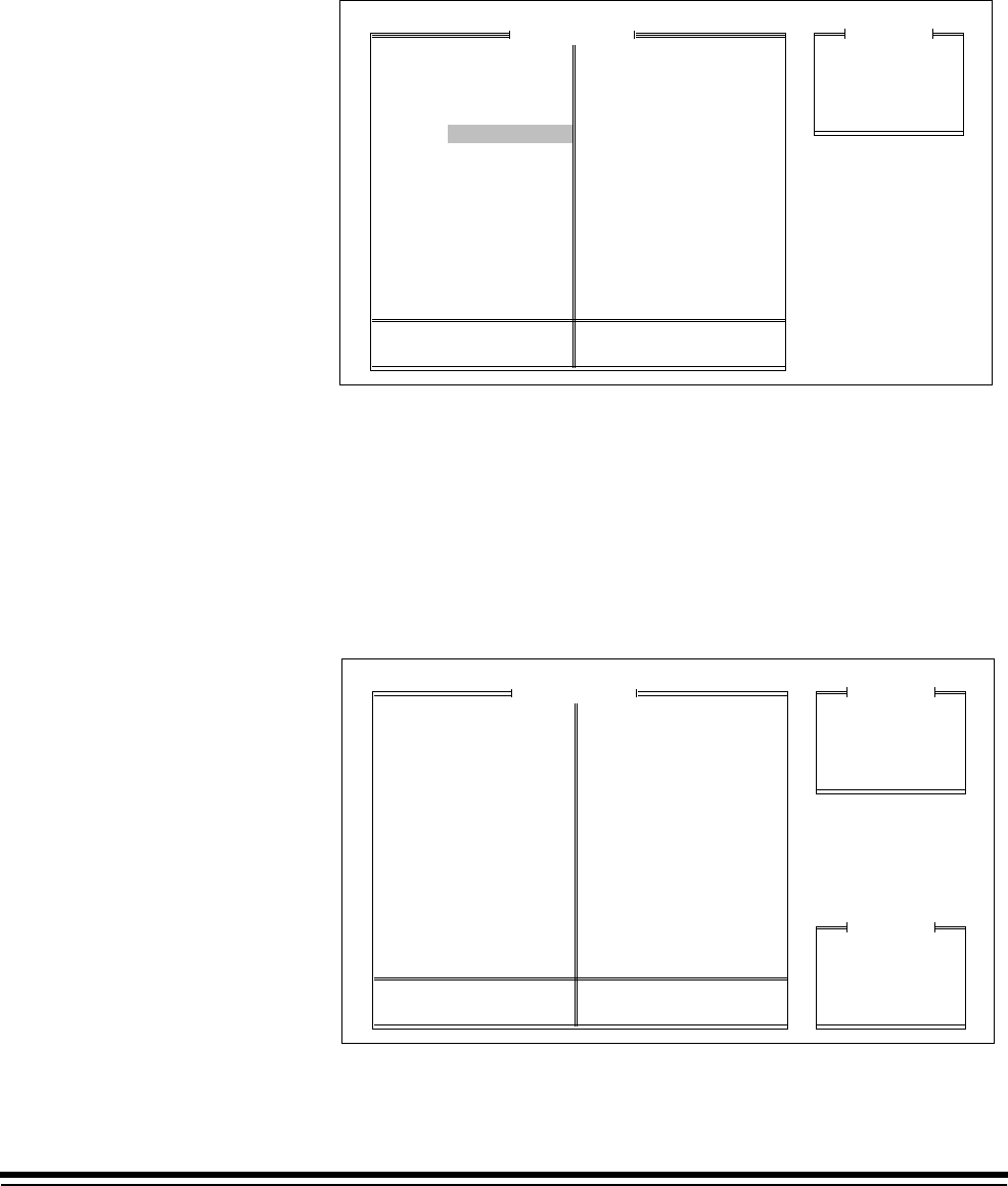
3-14 A-61097 May 1997
Batching
This mode defines the number of documents of a specified level to
process prior to performing a predefined action.
■Microimager 70 ■Microimager 70/AFM ■Scanner 900
■Scanner 923 ■Scanner/Microimager 990 ■Scanner 9500
1. Select Batching.
Batch Level
Batch Value
Start of Batch Function
End of Batch Function
Previous Menu
Mode Configuration
Don't Save & End Session
End Configuration
Save & End Session
Previous Menu
Mode Number: 10 Mode Name: MODE10
FieldMode Configuration
Don't Save & End Session
End Configuration
Save & End Session
Previous Menu
Mode Number: 10 Mode Name: MODE10
Batching
MODE 10
3 Lvl
Supprs
4233
2112
None
Auto
Duplex
?????
1 Roll
Comic
Off
Off
Off
Xport
Off
Undef
Undef
Off
Off
Off
Lvl 2
Off
N N N
Off
On
Disply
Off
Off
Off
Off
No Sav
F
Mode Name
Index Format
IA Display Format
IA Field Widths
Level Rules
Batching
AEC Mode
Film Mode
Reduction Ratio
# of Cassettes
Film Writer
Image Mgmt Code
Length Monitor
Skew Monitor
Check Stacker
Endorser
Not Used
Ftswitch Pressed
Ftswitch Released
Ftswitch Cnf Tone
Patch Reader 1
Patch Reader 2
Patch Definition
Bar Code
Confirmation Tone
OCR Status
COIN User Channel
Printer Control
Primary DP-1
Secondary DP-1
Doc. Printer 12
Document Sorter
Mode Overrides
Film Definition
Batch Level This mode defines the level of the documents to be counted. The default
value is None.
■Microimager 70 ■Microimager 70/AFM ■Scanner 900
■Scanner 923 ■Scanner/Microimager 990 ■Scanner 9500
1. Select Batch Level.
Batch Level
Batch Value
Start of Batch Function
End of Batch Function
Previous Menu
Mode Configuration
Don't Save & End Session
End Configuration
Save & End Session
Previous Menu
Mode Number: 10 Mode Name: MODE10
Field
Level 1
Level 2
Level 3
None
Previous Menu
Batch Field
Mode Configuration
Don't Save & End Session
End Configuration
Save & End Session
Previous Menu
Mode Number: 10 Mode Name: MODE10
Batching
MODE 10
3 Lvl
Supprs
4233
2112
None
Auto
Duplex
?????
1 Roll
Comic
Off
Off
Off
Xport
Off
Undef
Undef
Off
Off
Off
Lvl 2
Off
N N N
Off
On
Disply
Off
Off
Off
Off
No Sav
F
Mode Name
Index Format
IA Display Format
IA Field Widths
Level Rules
Batching
AEC Mode
Film Mode
Reduction Ratio
# of Cassettes
Film Writer
Image Mgmt Code
Length Monitor
Skew Monitor
Check Stacker
Endorser
Not Used
Ftswitch Pressed
Ftswitch Released
Ftswitch Cnf Tone
Patch Reader 1
Patch Reader 2
Patch Definition
Bar Code
Confirmation Tone
OCR Status
COIN User Channel
Printer Control
Primary DP-1
Secondary DP-1
Doc. Printer 12
Document Sorter
Mode Overrides
Film Definition
2. Select the desired batch level.
NOTE: If you select None, you can’t set Batch Value.

A-61097 May 1997 3-15
Batch Value
Defines the number of documents to be counted prior to performing a
predefined action. The default value is 99.
■Microimager 70 ■Microimager 70/AFM ■Scanner 900
■Scanner 923 ■Scanner/Microimager 990 ■Scanner 9500
1. Select Batch Value.
Batch Level
Batch Value
Start of Batch Function
End of Batch Function
Previous Menu
Mode Configuration
Don't Save & End Session
End Configuration
Save & End Session
Previous Menu
Mode Number: 10 Mode Name: MODE10
FieldMode Configuration
Don't Save & End Session
End Configuration
Save & End Session
Previous Menu
Mode Number: 10 Mode Name: MODE10
Batching
Enter Batch Value
99
Range: 1-99
MODE 10
3 Lvl
Supprs
4233
2112
None
Auto
Duplex
?????
1 Roll
Comic
Off
Off
Off
Xport
Off
Undef
Undef
Off
Off
Off
Lvl 2
Off
N N N
Off
On
Disply
Off
Off
Off
Off
No Sav
F
Mode Name
Index Format
IA Display Format
IA Field Widths
Level Rules
Batching
AEC Mode
Film Mode
Reduction Ratio
# of Cassettes
Film Writer
Image Mgmt Code
Length Monitor
Skew Monitor
Check Stacker
Endorser
Not Used
Ftswitch Pressed
Ftswitch Released
Ftswitch Cnf Tone
Patch Reader 1
Patch Reader 2
Patch Definition
Bar Code
Confirmation Tone
OCR Status
COIN User Channel
Printer Control
Primary DP-1
Secondary DP-1
Doc. Printer 12
Document Sorter
Mode Overrides
Film Definition
2. Enter the number of documents to be counted as a batch.
The value entered should be between 1 and the maximum image
address size for the field (or 9999, whichever is less).
Use the following information to determine the maximum number
allowed:
— If the length of the level field is 1, the maximum batching value is 9.
— If the length of the level field is 2, the maximum batching value is
99.
— If the length of the level field is 3, the maximum batching value is
999.
— If the length of the level field is 4, the maximum batching value is
9999.
— If the length of the level field is 5 – 9, the maximum batching value
is 99999.

3-16 A-61097 May 1997
Start of Batch Function
This mode defines the action(s) to be taken prior to processing the
document in the batch. The default value is Nothing.
❏Microimager 70 ■Microimager 70/AFM ■Scanner 900
■Scanner 923 ■Scanner/Microimager 990 ■Scanner 9500
1. Select Start of Batch Function.
Batch Level
Batch Value
Start of Batch Function
End of Batch Function
Previous Menu
Mode Configuration
Don't Save & End Session
End Configuration
Save & End Session
Previous Menu
Mode Number: 10 Mode Name: MODE10
FieldMode Configuration
Don't Save & End Session
End Configuration
Save & End Session
Previous Menu
Mode Number: 10 Mode Name: MODE10
Batching
Start-of-Batch Function
MODE 10
3 Lvl
Supprs
4233
2112
None
Auto
Duplex
?????
1 Roll
Comic
Off
Off
Off
Xport
Off
Undef
Undef
Off
Off
Off
Lvl 2
Off
N N N
Off
On
Disply
Off
Off
Off
Off
No Sav
F
Mode Name
Index Format
IA Display Format
IA Field Widths
Level Rules
Batching
AEC Mode
Film Mode
Reduction Ratio
# of Cassettes
Film Writer
Image Mgmt Code
Length Monitor
Skew Monitor
Check Stacker
Endorser
Not Used
Ftswitch Pressed
Ftswitch Released
Ftswitch Cnf Tone
Patch Reader 1
Patch Reader 2
Patch Definition
Bar Code
Confirmation Tone
OCR Status
COIN User Channel
Printer Control
Primary DP-1
Secondary DP-1
Doc. Printer 12
Document Sorter
Mode Overrides
Film Definition
2. Enter the function(s) to be performed prior to batch processing. Valid
Start-of-Batch functions are:
–f94 go to Level 1
–f95 go to Level 2
–f96 go to Level 3

A-61097 May 1997 3-17
End of Batch Function
This mode defines the action(s) to be taken after processing the document
in the batch. The default value is f98, Stop.
❏Microimager 70 ■Microimager 70/AFM ■Scanner 900
■Scanner 923 ■Scanner/Microimager 990 ■Scanner 9500
1. Select End of Batch Function.
Batch Level
Batch Value
Start of Batch Function
End of Batch Function
Previous Menu
Mode Configuration
Don't Save & End Session
End Configuration
Save & End Session
Previous Menu
Mode Number: 10 Mode Name: MODE10
FieldMode Configuration
Don't Save & End Session
End Configuration
Save & End Session
Previous Menu
Mode Number: 10 Mode Name: MODE10
Batching
End-of-Batch Function
MODE 10
3 Lvl
Supprs
4233
2112
None
Auto
Duplex
?????
1 Roll
Comic
Off
Off
Off
Xport
Off
Undef
Undef
Off
Off
Off
Lvl 2
Off
N N N
Off
On
Disply
Off
Off
Off
Off
No Sav
F
Mode Name
Index Format
IA Display Format
IA Field Widths
Level Rules
Batching
AEC Mode
Film Mode
Reduction Ratio
# of Cassettes
Film Writer
Image Mgmt Code
Length Monitor
Skew Monitor
Check Stacker
Endorser
Not Used
Ftswitch Pressed
Ftswitch Released
Ftswitch Cnf Tone
Patch Reader 1
Patch Reader 2
Patch Definition
Bar Code
Confirmation Tone
OCR Status
COIN User Channel
Printer Control
Primary DP-1
Secondary DP-1
Doc. Printer 12
Document Sorter
Mode Overrides
Film Definition
2. Enter the function(s) to be performed after batch processing.
–f94 go to Level 1
–f95 go to Level 2
–f96 go to Level 3
–f98 Stop

3-18 A-61097 May 1997
AEC Mode
This mode enables or disables Automatic Exposure Control. Fixed Mode
disables Automatic Exposure Control. Auto Mode enables Automatic
Exposure Control. The default value is Auto Mode.
■Microimager 70 ■Microimager 70/AFM ❏Scanner 900
❏Scanner 923 ■Scanner/Microimager 990 ❏Scanner 9500
1. Select AEC Mode.
Fixed Mode
Auto Mode
Previous Menu
Mode Configuration
Don't Save & End Session
End Configuration
Save & End Session
Previous Menu
Mode Number: 10 Mode Name: MODE10
FieldMode Configuration
Don't Save & End Session
End Configuration
Save & End Session
Previous Menu
Mode Number: 10 Mode Name: MODE10
AEC Status
MODE 10
3 Lvl
Supprs
4233
2112
None
Auto
Duplex
?????
1 Roll
Comic
Off
Off
Off
Xport
Off
Undef
Undef
Off
Off
Off
Lvl 2
Off
N N N
Off
On
Disply
Off
Off
Off
Off
No Sav
F
Mode Name
Index Format
IA Display Format
IA Field Widths
Level Rules
Batching
AEC Mode
Film Mode
Reduction Ratio
# of Cassettes
Film Writer
Image Mgmt Code
Length Monitor
Skew Monitor
Check Stacker
Endorser
Not Used
Ftswitch Pressed
Ftswitch Released
Ftswitch Cnf Tone
Patch Reader 1
Patch Reader 2
Patch Definition
Bar Code
Confirmation Tone
OCR Status
COIN User Channel
Printer Control
Primary DP-1
Secondary DP-1
Doc. Printer 12
Document Sorter
Mode Overrides
Film Definition
2. Select the desired AEC mode.
NOTE: AEC mode is not available on the scanners.
A-61097 May 1997 3-19
Film Mode
This mode defines the orientation of documents on film. Refer to
Description 5: Film Modes for a description of the available film modes.
The default value is Duplex.
■Microimager 70 ■Microimager 70/AFM ❏Scanner 900
❏Scanner 923 ■Scanner/Microimager 990 ❏Scanner 9500
1. Select Film Mode.
Simplex Mode
Duplex Mode
Duo Mode
Previous Menu
Mode Configuration
Don't Save & End Session
End Configuration
Save & End Session
Previous Menu
Mode Number: 10 Mode Name: MODE10
FieldMode Configuration
Don't Save & End Session
End Configuration
Save & End Session
Previous Menu
Mode Number: 10 Mode Name: MODE10
AEC Status
Simplx
50X
40X
24X
Duo
50X
40X
Duplex
50X
40X
f b
MODE 10
3 Lvl
Supprs
4233
2112
None
Auto
Duplex
?????
1 Roll
Comic
Off
Off
Off
Xport
Off
Undef
Undef
Off
Off
Off
Lvl 2
Off
N N N
Off
On
Disply
Off
Off
Off
Off
No Sav
F
Mode Name
Index Format
IA Display Format
IA Field Widths
Level Rules
Batching
AEC Mode
Film Mode
Reduction Ratio
# of Cassettes
Film Writer
Image Mgmt Code
Length Monitor
Skew Monitor
Check Stacker
Endorser
Not Used
Ftswitch Pressed
Ftswitch Released
Ftswitch Cnf Tone
Patch Reader 1
Patch Reader 2
Patch Definition
Bar Code
Confirmation Tone
OCR Status
COIN User Channel
Printer Control
Primary DP-1
Secondary DP-1
Doc. Printer 12
Document Sorter
Mode Overrides
Film Definition
2. Select the desired film mode.
NOTE: If you intend to link the current mode with another mode, the film
mode chosen for both modes must be compatible. Simplex mode
is compatible with either simplex mode or duplex mode. Duplex
mode is compatible with either simplex mode or duplex mode.
Duo mode is compatible only with duo mode.
NOTE: Film mode is not available on the scanners.
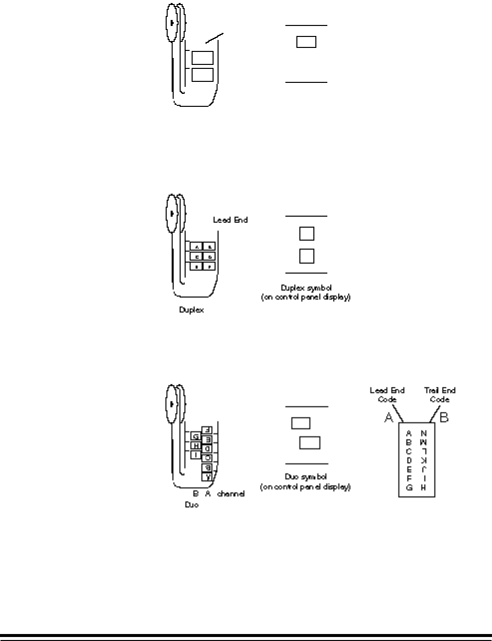
3-20 A-61097 May 1997
• Simplex Mode
Simplex format allows one image to be exposed across the film width. A
24:1 reduction ratio is used for this format.
• Duplex Mode
Duplex format allows front and back images of the same document to
be exposed (at the same time) across the film width. A 40:1 or 50:1
reduction ratio is used for this format.
• Duo Mode
Duo format allows documents to be filmed across one-half of the film
width, with additional documents filmed on the adjacent side. A 40:1 or
50:1 reduction ratio is used for this format.

A-61097 May 1997 3-21
Reduction Ratio
This mode defines the level of magnification. The default value is Don’t
Care.
❏Microimager 70 ■Microimager 70/AFM ❏Scanner 900
❏Scanner 923 ■Scanner/Microimager 990 ❏Scanner 9500
1. Select Reduction Ratio.
Reduction Ratio
Don't Care
24x
40x
50x
Previous Menu
Mode Configuration
Don't Save & End Session
End Configuration
Save & End Session
Previous Menu
Mode Number: 10 Mode Name: MODE10
Don't Save & End Session
End Configuration
Save & End Session
Previous Menu
Mode Name: MODE10
MODE 10
3 Lvl
Supprs
4233
2112
None
Auto
Duplex
?????
1 Roll
Comic
Off
Off
Off
Xport
Off
Undef
Undef
Off
Off
Off
Lvl 2
Off
N N N
Off
On
Disply
Off
Off
Off
Off
No Sav
F
Mode Name
Index Format
IA Display Format
IA Field Widths
Level Rules
Batching
AEC Mode
Film Mode
Reduction Ratio
# of Cassettes
Film Writer
Image Mgmt Code
Length Monitor
Skew Monitor
Check Stacker
Endorser
Not Used
Ftswitch Pressed
Ftswitch Released
Ftswitch Cnf Tone
Patch Reader 1
Patch Reader 2
Patch Definition
Bar Code
Confirmation Tone
OCR Status
COIN User Channel
Printer Control
Primary DP-1
Secondary DP-1
Doc. Printer 12
Document Sorter
Mode Overrides
Film Definition
2. Select the desired reduction ratio.
Use the following information to determine the reduction allowed
based upon the Film Mode selected:
— If the film mode is Simplex, you may select 50X, 40X, or 24X.
— If the film mode is Duplex, you may select 50X or 40X.
— If the film mode is Duo, you may select 50X or 40X.
NOTE: This selection is not available on the scanners.

3-22 A-61097 May 1997
Number of Cassettes
This mode defines the minimum number of cassettes that must be
installed during filming. If Two Cassettes is chosen, you must always use
two cassettes. If One Cassette is chosen, you may use one or two
cassettes. The default value is One Cassette.
■Microimager 70 ■Microimager 70/AFM ❏Scanner 900
❏Scanner 923 ■Scanner/Microimager 990 ❏Scanner 9500
1. Select # of Cassettes.
Two Cassettes
One Cassette
Previous Menu
Mode Configuration
Don't Save & End Session
End Configuration
Save & End Session
Previous Menu
Mode Number: 10 Mode Name: MODE10
FieldCassettes Req'd
MODE 10
3 Lvl
Supprs
4233
2112
None
Auto
Duplex
?????
1 Roll
Comic
Off
Off
Off
Xport
Off
Undef
Undef
Off
Off
Off
Lvl 2
Off
N N N
Off
On
Disply
Off
Off
Off
Off
No Sav
F
Mode Name
Index Format
IA Display Format
IA Field Widths
Level Rules
Batching
AEC Mode
Film Mode
Reduction Ratio
# of Cassettes
Film Writer
Image Mgmt Code
Length Monitor
Skew Monitor
Check Stacker
Endorser
Not Used
Ftswitch Pressed
Ftswitch Released
Ftswitch Cnf Tone
Patch Reader 1
Patch Reader 2
Patch Definition
Bar Code
Confirmation Tone
OCR Status
COIN User Channel
Printer Control
Primary DP-1
Secondary DP-1
Doc. Printer 12
Document Sorter
Mode Overrides
Film Definition
2. Select the minimum number of cassettes required.
NOTE: This selection is not available on the scanners.

A-61097 May 1997 3-23
Film Writer
NOTE: The Film Writing Module must be installed.
■Microimager 70 ■Microimager 70/AFM ❏Scanner 900
❏Scanner 923 ■Scanner/Microimager 990 ❏Scanner 9500
1. Select Film Writer.
Character Orientation
Image Addr Print Format
Same Sequence per Level
Print Sequence - Level 0
Print Sequence - Level 1
Print Sequence - Level 2
Print Sequence - Level 3
Previous Menu
Mode Configuration
Don't Save & End Session
End Configuration
Save & End Session
Previous Menu
Mode Number: 10 Mode Name: MODE10
Advanced Film Writer
MODE 10
3 Lvl
Supprs
4233
2112
None
Auto
Duplex
?????
1 Roll
Comic
Off
Off
Off
Xport
Off
Undef
Undef
Off
Off
Off
Lvl 2
Off
N N N
Off
On
Disply
Off
Off
Off
Off
No Sav
F
Mode Name
Index Format
IA Display Format
IA Field Widths
Level Rules
Batching
AEC Mode
Film Mode
Reduction Ratio
# of Cassettes
Film Writer
Image Mgmt Code
Length Monitor
Skew Monitor
Check Stacker
Endorser
Not Used
Ftswitch Pressed
Ftswitch Released
Ftswitch Cnf Tone
Patch Reader 1
Patch Reader 2
Patch Definition
Bar Code
Confirmation Tone
OCR Status
COIN User Channel
Printer Control
Primary DP-1
Secondary DP-1
Doc. Printer 12
Document Sorter
Mode Overrides
Film Definition
NOTE: This selection is not available on the scanners.
3-24 A-61097 May 1997
Character Orientation
This mode defines the orientation of the information printed by the film
writer. The default is Comic.
■Microimager 70 ■Microimager 70/AFM ❏Scanner 900
❏Scanner 923 ■Scanner/Microimager 990 ❏Scanner 9500
1. Select Character Orientation.
Character Orientation
Image Addr Print Format
Same Sequence per Level
Print Sequence - Level 0
Print Sequence - Level 1
Print Sequence - Level 2
Print Sequence - Level 3
Previous Menu
Mode Configuration
Don't Save & End Session
End Configuration
Save & End Session
Previous Menu
Mode Number: 10 Mode Name: MODE10
Advanced Film Writer
Orientation
Comic
Cine
Comic 180
Cine 180
Previous Menu
MODE 10
3 Lvl
Supprs
4233
2112
None
Auto
Duplex
?????
1 Roll
Comic
Off
Off
Off
Xport
Off
Undef
Undef
Off
Off
Off
Lvl 2
Off
N N N
Off
On
Disply
Off
Off
Off
Off
No Sav
F
Mode Name
Index Format
IA Display Format
IA Field Widths
Level Rules
Batching
AEC Mode
Film Mode
Reduction Ratio
# of Cassettes
Film Writer
Image Mgmt Code
Length Monitor
Skew Monitor
Check Stacker
Endorser
Not Used
Ftswitch Pressed
Ftswitch Released
Ftswitch Cnf Tone
Patch Reader 1
Patch Reader 2
Patch Definition
Bar Code
Confirmation Tone
OCR Status
COIN User Channel
Printer Control
Primary DP-1
Secondary DP-1
Doc. Printer 12
Document Sorter
Mode Overrides
Film Definition
2. Select the desired orientation.
A-61097 May 1997 3-25
Image Address Print Format
This mode defines the format of the Image Address printed on film.
The default is Compress.
❏Microimager 70 ■Microimager 70/AFM ❏Scanner 900
❏Scanner 923 ■Scanner/Microimager 990 ❏Scanner 9500
1. Select Image Addr Print Format.
Character Orientation
Image Addr Print Format
Same Sequence per Level
Print Sequence - Level 0
Print Sequence - Level 1
Print Sequence - Level 2
Print Sequence - Level 3
Previous Menu
Mode Configuration
Don't Save & End Session
End Configuration
Save & End Session
Previous Menu
Mode Number: 10 Mode Name: MODE10
Advanced Film Writer
Display Leading Zeros
Compress Leading Zeros
Suppress Leading Zeros
Previous Menu
Film Writer IA Format
Display:
Compress:
Suppress:
001.002.003.004
001.2.3.4
001.002.00 3.004
Examples of Formats
MODE 10
3 Lvl
Supprs
4233
2112
None
Auto
Duplex
?????
1 Roll
Comic
Off
Off
Off
Xport
Off
Undef
Undef
Off
Off
Off
Lvl 2
Off
N N N
Off
On
Disply
Off
Off
Off
Off
No Sav
F
Mode Name
Index Format
IA Display Format
IA Field Widths
Level Rules
Batching
AEC Mode
Film Mode
Reduction Ratio
# of Cassettes
Film Writer
Image Mgmt Code
Length Monitor
Skew Monitor
Check Stacker
Endorser
Not Used
Ftswitch Pressed
Ftswitch Released
Ftswitch Cnf Tone
Patch Reader 1
Patch Reader 2
Patch Definition
Bar Code
Confirmation Tone
OCR Status
COIN User Channel
Printer Control
Primary DP-1
Secondary DP-1
Doc. Printer 12
Document Sorter
Mode Overrides
Film Definition
2. Select the desired format option.

3-26 A-61097 May 1997
Write Definitions
This mode defines the information printed on film next to each document,
based upon the document level. The default value for all levels is
<FF/IA-All Del>.
■Microimager 70 ■Microimager 70/AFM ❏Scanner 900
❏Scanner 923 ■Scanner/Microimager 990 ❏Scanner 9500
When using a Microimager 70 without the Advanced Function Module
installed, a limited number of print items are available. The available print
items are:
• Full Image Address
• Indexed Fields Only
• Nothing Printed
When using a Microimager 70 with the Advanced Function Module
installed, or Scanner/Microimager 990, all print items may be used.
If the same information is to be printed next to documents of all levels:
1. Select Same Sequence per Level.
Full Image Address
Indexed Fields Only
Current Field Level
Spaces between Items
Current Day
Current Date
Current Time
Document Counter
Message 1
Message 2
Message 3
Message 4
Message 5
Message 6
Message 7
Message 8
Message 9
Nothing Printed
Previous Menu
FAN Write Sequence
Current Print Sequence Display Values
New Print Sequence Display Values
<Full IA> <2 Sp> <Date> <2Sp> <Time>
Default is <FF/IA - All Del>
2. Select the item(s) to be printed.
NOTE: If the definition exceeds the thirty-eight (38) character limit, the
first thirty-eight (38) characters will be printed on film next to each
document and the remainder of the information will be truncated.
New information will appear in the New Print Sequence Display
Values box. When you press Enter, the print sequence will appear
in the upper box.

A-61097 May 1997 3-27
If different information is to be printed next to documents of different
levels:
1. Select Print Sequence – Level # for the desired level.
Full Image Address
Indexed Fields Only
Current Field Level
Spaces between Items
Current Day
Current Date
Current Time
Document Counter
Message 1
Message 2
Message 3
Message 4
Message 5
Message 6
Message 7
Message 8
Message 9
Nothing Printed
Previous Menu
FAN Write Sequence
Current Print Sequence Display Values
New Print Sequence Display Values
<Full IA> <2 Sp> <Date> <2Sp> <Time>
Default is <FF/IA - All Del>
2. Select the item(s) to be printed.
NOTE: If the definition exceeds the thirty-eight (38) character limit, the
first thirty-eight (38) characters will be printed on film next to each
document and the remainder of the information will be truncated.

3-28 A-61097 May 1997
Image Management Code
NOTE: The Film Writing Module must be installed.
■Microimager 70 ■Microimager 70/AFM ❏Scanner 900
❏Scanner 923 ■Scanner/Microimager 990 ❏Scanner 9500
1. Select Image Mgmt Code.
Status
IMT Search Prg Number
Magnification
Splice Definition
Image Mark Sizes
Image Polarity
Duplex Front Location
Film Image Orientation
Image Offset
Previous Menu
Mode Configuration
Don't Save & End Session
End Configuration
Save & End Session
Previous Menu
Mode Number: 10 Mode Name: MODE10
Image Management Code
MODE 10
3 Lvl
Supprs
4233
2112
None
Auto
Duplex
?????
1 Roll
Comic
Off
Off
Off
Xport
Off
Undef
Undef
Off
Off
Off
Lvl 2
Off
N N N
Off
On
Disply
Off
Off
Off
Off
No Sav
F
Mode Name
Index Format
IA Display Format
IA Field Widths
Level Rules
Batching
AEC Mode
Film Mode
Reduction Ratio
# of Cassettes
Film Writer
Image Mgmt Code
Length Monitor
Skew Monitor
Check Stacker
Endorser
Not Used
Ftswitch Pressed
Ftswitch Released
Ftswitch Cnf Tone
Patch Reader 1
Patch Reader 2
Patch Definition
Bar Code
Confirmation Tone
OCR Status
COIN User Channel
Printer Control
Primary DP-1
Secondary DP-1
Doc. Printer 12
Document Sorter
Mode Overrides
Film Definition
NOTE: This selection is not available on the scanners.
A-61097 May 1997 3-29
Status
This mode enables or disables the use of IMC options. The default value
is Off or Disabled.
■Microimager 70 ■Microimager 70/AFM ❏Scanner 900
❏Scanner 923 ■Scanner/Microimager 990 ❏Scanner 9500
1. Select Status.
Status
IMT Search Prg Number
Magnification
Splice Definition
Image Mark Sizes
Image Polarity
Duplex Front Location
Film Image Orientation
Image Offset
Previous Menu
Mode Configuration
Don't Save & End Session
End Configuration
Save & End Session
Previous Menu
Mode Number: 10 Mode Name: MODE10
Image Management Code
Off or Diabled
On or Enabled
Previous Menu
FieldIMC Status
MODE 10
3 Lvl
Supprs
4233
2112
None
Auto
Duplex
?????
1 Roll
Comic
Off
Off
Off
Xport
Off
Undef
Undef
Off
Off
Off
Lvl 2
Off
N N N
Off
On
Disply
Off
Off
Off
Off
No Sav
F
Mode Name
Index Format
IA Display Format
IA Field Widths
Level Rules
Batching
AEC Mode
Film Mode
Reduction Ratio
# of Cassettes
Film Writer
Image Mgmt Code
Length Monitor
Skew Monitor
Check Stacker
Endorser
Not Used
Ftswitch Pressed
Ftswitch Released
Ftswitch Cnf Tone
Patch Reader 1
Patch Reader 2
Patch Definition
Bar Code
Confirmation Tone
OCR Status
COIN User Channel
Printer Control
Primary DP-1
Secondary DP-1
Doc. Printer 12
Document Sorter
Mode Overrides
Film Definition
2. Select the desired status.
NOTE: If the status is defined as Off or Disabled, definitions for the
remaining IMC options will be ignored.

3-30 A-61097 May 1997
IMT Search Program Number
This mode defines the IMT search program number. The default value is
00.
■Microimager 70 ■Microimager 70/AFM ❏Scanner 900
❏Scanner 923 ■Scanner/Microimager 990 ❏Scanner 9500
1. Select IMT Search Prg Number.
Status
IMT Search Prg Number
Magnification
Splice Definition
Image Mark Sizes
Image Polarity
Duplex Front Location
Film Image Orientation
Image Offset
Previous Menu
Mode Configuration
Don't Save & End Session
End Configuration
Save & End Session
Previous Menu
Mode Number: 10 Mode Name: MODE10
Image Management Code
Enter Program Number
00
Range: 0 - 70
MODE 10
3 Lvl
Supprs
4233
2112
None
Auto
Duplex
?????
1 Roll
Comic
Off
Off
Off
Xport
Off
Undef
Undef
Off
Off
Off
Lvl 2
Off
N N N
Off
On
Disply
Off
Off
Off
Off
No Sav
F
Mode Name
Index Format
IA Display Format
IA Field Widths
Level Rules
Batching
AEC Mode
Film Mode
Reduction Ratio
# of Cassettes
Film Writer
Image Mgmt Code
Length Monitor
Skew Monitor
Check Stacker
Endorser
Not Used
Ftswitch Pressed
Ftswitch Released
Ftswitch Cnf Tone
Patch Reader 1
Patch Reader 2
Patch Definition
Bar Code
Confirmation Tone
OCR Status
COIN User Channel
Printer Control
Primary DP-1
Secondary DP-1
Doc. Printer 12
Document Sorter
Mode Overrides
Film Definition
2. Enter a two-digit program number.

A-61097 May 1997 3-31
Magnification
This mode defines for the KODAK IMAGELINK™ Digital Workstation (with
Zoom Lens Accessory) the desired level of magnification. The default
value is 20.
■Microimager 70 ■Microimager 70/AFM ❏Scanner 900
❏Scanner 923 ■Scanner/Microimager 990 ❏Scanner 9500
1. Select Magnification.
Status
IMT Search Prg Number
Magnification
Splice Definition
Image Mark Sizes
Image Polarity
Duplex Front Location
Film Image Orientation
Image Offset
Previous Menu
Mode Configuration
Don't Save & End Session
End Configuration
Save & End Session
Previous Menu
Mode Number: 10 Mode Name: MODE10
Image Management Code
Enter Magnification
20
Range: 0 or 20 - 80
Use 0 for RIM 2000 Code
MODE 10
3 Lvl
Supprs
4233
2112
None
Auto
Duplex
?????
1 Roll
Comic
Off
Off
Off
Xport
Off
Undef
Undef
Off
Off
Off
Lvl 2
Off
N N N
Off
On
Disply
Off
Off
Off
Off
No Sav
F
Mode Name
Index Format
IA Display Format
IA Field Widths
Level Rules
Batching
AEC Mode
Film Mode
Reduction Ratio
# of Cassettes
Film Writer
Image Mgmt Code
Length Monitor
Skew Monitor
Check Stacker
Endorser
Not Used
Ftswitch Pressed
Ftswitch Released
Ftswitch Cnf Tone
Patch Reader 1
Patch Reader 2
Patch Definition
Bar Code
Confirmation Tone
OCR Status
COIN User Channel
Printer Control
Primary DP-1
Secondary DP-1
Doc. Printer 12
Document Sorter
Mode Overrides
Film Definition
2. Enter the desired magnification level within the range 0 or 20 – 80.

3-32 A-61097 May 1997
Splice Definition
This mode defines the desired action when a splice is detected. The
default value is Ignore.
■Microimager 70 ■Microimager 70/AFM ❏Scanner 900
❏Scanner 923 ■Scanner/Microimager 990 ❏Scanner 9500
1. Select Splice Definition.
Select any of the Sort Criteria and the following screen appears:
Status
IMT Search Prg Number
Magnification
Splice Definition
Image Mark Sizes
Image Polarity
Duplex Front Location
Film Image Orientation
Image Offset
Previous Menu
Mode Configuration
Don't Save & End Session
End Configuration
Save & End Session
Previous Menu
Mode Number: 10 Mode Name: MODE10
Image Management Code
Splice
Ignore
Level 1
Level 2
Level 3
Previous Menu
MODE 10
3 Lvl
Supprs
4233
2112
None
Auto
Duplex
?????
1 Roll
Comic
Off
Off
Off
Xport
Off
Undef
Undef
Off
Off
Off
Lvl 2
Off
N N N
Off
On
Disply
Off
Off
Off
Off
No Sav
F
Mode Name
Index Format
IA Display Format
IA Field Widths
Level Rules
Batching
AEC Mode
Film Mode
Reduction Ratio
# of Cassettes
Film Writer
Image Mgmt Code
Length Monitor
Skew Monitor
Check Stacker
Endorser
Not Used
Ftswitch Pressed
Ftswitch Released
Ftswitch Cnf Tone
Patch Reader 1
Patch Reader 2
Patch Definition
Bar Code
Confirmation Tone
OCR Status
COIN User Channel
Printer Control
Primary DP-1
Secondary DP-1
Doc. Printer 12
Document Sorter
Mode Overrides
Film Definition
2. Select the desired action.

A-61097 May 1997 3-33
Image Mark Sizes
This mode defines the image mark sizes used (small, medium, and large).
The default value is Kodak Standard.
■Microimager 70 ■Microimager 70/AFM ❏Scanner 900
❏Scanner 923 ■Scanner/Microimager 990 ❏Scanner 9500
1. Select Image Mark Sizes.
Status
IMT Search Prg Number
Magnification
Splice Definition
Image Mark Sizes
Image Polarity
Duplex Front Location
Film Image Orientation
Image Offset
Previous Menu
Mode Configuration
Don't Save & End Session
End Configuration
Save & End Session
Previous Menu
Mode Number: 10 Mode Name: MODE10
Image Management Code
Custom Setup
Kodak Standard
Previous Menu
FieldImage Mark Size
MODE 10
3 Lvl
Supprs
4233
2112
None
Auto
Duplex
?????
1 Roll
Comic
Off
Off
Off
Xport
Off
Undef
Undef
Off
Off
Off
Lvl 2
Off
N N N
Off
On
Disply
Off
Off
Off
Off
No Sav
F
Mode Name
Index Format
IA Display Format
IA Field Widths
Level Rules
Batching
AEC Mode
Film Mode
Reduction Ratio
# of Cassettes
Film Writer
Image Mgmt Code
Length Monitor
Skew Monitor
Check Stacker
Endorser
Not Used
Ftswitch Pressed
Ftswitch Released
Ftswitch Cnf Tone
Patch Reader 1
Patch Reader 2
Patch Definition
Bar Code
Confirmation Tone
OCR Status
COIN User Channel
Printer Control
Primary DP-1
Secondary DP-1
Doc. Printer 12
Document Sorter
Mode Overrides
Film Definition
2. Select the desired Image Mark Size option.
Custom Setup should only be selected if the Kodak Field Engineer
has defined the customer image mark sizes (small, medium, and
large).
3-34 A-61097 May 1997
Image Polarity
This mode defines the polarity of the image marks relative to the polarity
of the document images. The default value is Same as Image Mark.
■Microimager 70 ■Microimager 70/AFM ❏Scanner 900
❏Scanner 923 ■Scanner/Microimager 990 ❏Scanner 9500
1. Select Image Polarity.
Status
IMT Search Prg Number
Magnification
Splice Definition
Image Mark Sizes
Image Polarity
Duplex Front Location
Film Image Orientation
Image Offset
Previous Menu
Mode Configuration
Don't Save & End Session
End Configuration
Save & End Session
Previous Menu
Mode Number: 10 Mode Name: MODE10
Image Management Code
Opposite of Image Mark
Same as Image Mark
Previous Menu
FieldImage Polarity
MODE 10
3 Lvl
Supprs
4233
2112
None
Auto
Duplex
?????
1 Roll
Comic
Off
Off
Off
Xport
Off
Undef
Undef
Off
Off
Off
Lvl 2
Off
N N N
Off
On
Disply
Off
Off
Off
Off
No Sav
F
Mode Name
Index Format
IA Display Format
IA Field Widths
Level Rules
Batching
AEC Mode
Film Mode
Reduction Ratio
# of Cassettes
Film Writer
Image Mgmt Code
Length Monitor
Skew Monitor
Check Stacker
Endorser
Not Used
Ftswitch Pressed
Ftswitch Released
Ftswitch Cnf Tone
Patch Reader 1
Patch Reader 2
Patch Definition
Bar Code
Confirmation Tone
OCR Status
COIN User Channel
Printer Control
Primary DP-1
Secondary DP-1
Doc. Printer 12
Document Sorter
Mode Overrides
Film Definition
2. Select the desired polarity option.
NOTE: Select Opposite of Image Mark only when splicing the Image
Management Code onto the leading edge of film on which the
image mark polarity is opposite the document image polarity.

A-61097 May 1997 3-35
Duplex Front Location
The mode defines for the KODAK IMAGELINK™ Digital Workstation
where the front side image is located. The default value is Same as IM
Channel.
■Microimager 70 ■Microimager 70/AFM ❏Scanner 900
❏Scanner 923 ■Scanner/Microimager 990 ❏Scanner 9500
1. Select Duplex Front Location.
Status
IMT Search Prg Number
Magnification
Splice Definition
Image Mark Sizes
Image Polarity
Duplex Front Location
Film Image Orientation
Image Offset
Previous Menu
Mode Configuration
Don't Save & End Session
End Configuration
Save & End Session
Previous Menu
Mode Number: 10 Mode Name: MODE10
Image Management Code
Opposite of IM Channel
Same as IM Channel
Previous Menu
FieldDuplex Front Location
MODE 10
3 Lvl
Supprs
4233
2112
None
Auto
Duplex
?????
1 Roll
Comic
Off
Off
Off
Xport
Off
Undef
Undef
Off
Off
Off
Lvl 2
Off
N N N
Off
On
Disply
Off
Off
Off
Off
No Sav
F
Mode Name
Index Format
IA Display Format
IA Field Widths
Level Rules
Batching
AEC Mode
Film Mode
Reduction Ratio
# of Cassettes
Film Writer
Image Mgmt Code
Length Monitor
Skew Monitor
Check Stacker
Endorser
Not Used
Ftswitch Pressed
Ftswitch Released
Ftswitch Cnf Tone
Patch Reader 1
Patch Reader 2
Patch Definition
Bar Code
Confirmation Tone
OCR Status
COIN User Channel
Printer Control
Primary DP-1
Secondary DP-1
Doc. Printer 12
Document Sorter
Mode Overrides
Film Definition
2. Select the desired front side image location.
3-36 A-61097 May 1997
Film Image Orientation
The mode defines where the top of the image is located for the
KODAK IMAGELINK™ Digital Workstation. The default value is Leading
Edge Up.
■Microimager 70 ■Microimager 70/AFM ❏Scanner 900
❏Scanner 923 ■Scanner/Microimager 990 ❏Scanner 9500
1. Select Film Image Orientation.
Status
IMT Search Prg Number
Magnification
Splice Definition
Image Mark Sizes
Image Polarity
Duplex Front Location
Film Image Orientation
Image Offset
Previous Menu
Mode Configuration
Don't Save & End Session
End Configuration
Save & End Session
Previous Menu
Mode Number: 10 Mode Name: MODE10
Image Management Code
Leading Edge Down
Leading Edge Up
Previous Menu
FieldImage Orientation
MODE 10
3 Lvl
Supprs
4233
2112
None
Auto
Duplex
?????
1 Roll
Comic
Off
Off
Off
Xport
Off
Undef
Undef
Off
Off
Off
Lvl 2
Off
N N N
Off
On
Disply
Off
Off
Off
Off
No Sav
F
Mode Name
Index Format
IA Display Format
IA Field Widths
Level Rules
Batching
AEC Mode
Film Mode
Reduction Ratio
# of Cassettes
Film Writer
Image Mgmt Code
Length Monitor
Skew Monitor
Check Stacker
Endorser
Not Used
Ftswitch Pressed
Ftswitch Released
Ftswitch Cnf Tone
Patch Reader 1
Patch Reader 2
Patch Definition
Bar Code
Confirmation Tone
OCR Status
COIN User Channel
Printer Control
Primary DP-1
Secondary DP-1
Doc. Printer 12
Document Sorter
Mode Overrides
Film Definition
2. Select the desired image orientation.

A-61097 May 1997 3-37
Image Offset
This mode defines the position of the image marks relative to the leading
edge of the document. The default value is 0.
■Microimager 70 ■Microimager 70/AFM ❏Scanner 900
❏Scanner 923 ■Scanner/Microimager 990 ❏Scanner 9500
1. Select Image Offset.
Status
IMT Search Prg Number
Magnification
Splice Definition
Image Mark Sizes
Image Polarity
Duplex Front Location
Film Image Orientation
Image Offset
Previous Menu
Mode Configuration
Don't Save & End Session
End Configuration
Save & End Session
Previous Menu
Mode Number: 10 Mode Name: MODE10
Image Management Code
Enter Image Offset
000
Range: 0 - 127
MODE 10
3 Lvl
Supprs
4233
2112
None
Auto
Duplex
?????
1 Roll
Comic
Off
Off
Off
Xport
Off
Undef
Undef
Off
Off
Off
Lvl 2
Off
N N N
Off
On
Disply
Off
Off
Off
Off
No Sav
F
Mode Name
Index Format
IA Display Format
IA Field Widths
Level Rules
Batching
AEC Mode
Film Mode
Reduction Ratio
# of Cassettes
Film Writer
Image Mgmt Code
Length Monitor
Skew Monitor
Check Stacker
Endorser
Not Used
Ftswitch Pressed
Ftswitch Released
Ftswitch Cnf Tone
Patch Reader 1
Patch Reader 2
Patch Definition
Bar Code
Confirmation Tone
OCR Status
COIN User Channel
Printer Control
Primary DP-1
Secondary DP-1
Doc. Printer 12
Document Sorter
Mode Overrides
Film Definition
2. Enter a number within the range 0 - 127.

3-38 A-61097 May 1997
Length Monitor
NOTE: The Advanced Document Controller must be installed.
■Microimager 70 ■Microimager 70/AFM ■Scanner 900
■Scanner 923 ■Scanner/Microimager 990 ■Scanner 9500
1. Select Length Monitor.
Status
Max Document Length
Min Document Length
Length Err Response
Previous Menu
Mode Configuration
Don't Save & End Session
End Configuration
Save & End Session
Previous Menu
Mode Number: 10 Mode Name: MODE10
Length Monitor
MODE 10
3 Lvl
Supprs
4233
2112
None
Auto
Duplex
?????
1 Roll
Comic
Off
Off
Off
Xport
Off
Undef
Undef
Off
Off
Off
Lvl 2
Off
N N N
Off
On
Disply
Off
Off
Off
Off
No Sav
F
Mode Name
Index Format
IA Display Format
IA Field Widths
Level Rules
Batching
AEC Mode
Film Mode
Reduction Ratio
# of Cassettes
Film Writer
Image Mgmt Code
Length Monitor
Skew Monitor
Check Stacker
Endorser
Not Used
Ftswitch Pressed
Ftswitch Released
Ftswitch Cnf Tone
Patch Reader 1
Patch Reader 2
Patch Definition
Bar Code
Confirmation Tone
OCR Status
COIN User Channel
Printer Control
Primary DP-1
Secondary DP-1
Doc. Printer 12
Document Sorter
Mode Overrides
Film Definition

A-61097 May 1997 3-39
Status
This mode enables or disables length monitoring. The default value is Off
or Disabled.
■Microimager 70 ■Microimager 70/AFM ■Scanner 900
■Scanner 923 ■Scanner/Microimager 990 ■Scanner 9500
1. Select Status.
Status
Max Document Length
Min Document Length
Length Err Response
Previous Menu
Mode Configuration
Don't Save & End Session
End Configuration
Save & End Session
Previous Menu
Mode Number: 10 Mode Name: MODE10
Length Monitor
Off or Disabled
On or Enabled
Previous Menu
FieldLength Check
MODE 10
3 Lvl
Supprs
4233
2112
None
Auto
Duplex
?????
1 Roll
Comic
Off
Off
Off
Xport
Off
Undef
Undef
Off
Off
Off
Lvl 2
Off
N N N
Off
On
Disply
Off
Off
Off
Off
No Sav
F
Mode Name
Index Format
IA Display Format
IA Field Widths
Level Rules
Batching
AEC Mode
Film Mode
Reduction Ratio
# of Cassettes
Film Writer
Image Mgmt Code
Length Monitor
Skew Monitor
Check Stacker
Endorser
Not Used
Ftswitch Pressed
Ftswitch Released
Ftswitch Cnf Tone
Patch Reader 1
Patch Reader 2
Patch Definition
Bar Code
Confirmation Tone
OCR Status
COIN User Channel
Printer Control
Primary DP-1
Secondary DP-1
Doc. Printer 12
Document Sorter
Mode Overrides
Film Definition
2. Select the desired status.
NOTE: If Off or Disabled is selected, definitions for the remaining options
will be ignored.

3-40 A-61097 May 1997
Maximum Document Length
This mode defines the maximum document length accepted. The default
value is 13.000 inches/325 mm.
■Microimager 70 ■Microimager 70/AFM ■Scanner 900
■Scanner 923 ■Scanner/Microimager 990 ■Scanner 9500
1. Select Max Document Length.
Status
Max Document Length
Min Document Length
Length Err Response
Previous Menu
Mode Configuration
Don't Save & End Session
End Configuration
Save & End Session
Previous Menu
Mode Number: 10 Mode Name: MODE10
Length Monitor
Enter Max. Doc. Length
Range: 2.50...75.000
0013.00 inches
0330.20 metric
MODE 10
3 Lvl
Supprs
4233
2112
None
Auto
Duplex
?????
1 Roll
Comic
Off
Off
Off
Xport
Off
Undef
Undef
Off
Off
Off
Lvl 2
Off
N N N
Off
On
Disply
Off
Off
Off
Off
No Sav
F
Mode Name
Index Format
IA Display Format
IA Field Widths
Level Rules
Batching
AEC Mode
Film Mode
Reduction Ratio
# of Cassettes
Film Writer
Image Mgmt Code
Length Monitor
Skew Monitor
Check Stacker
Endorser
Not Used
Ftswitch Pressed
Ftswitch Released
Ftswitch Cnf Tone
Patch Reader 1
Patch Reader 2
Patch Definition
Bar Code
Confirmation Tone
OCR Status
COIN User Channel
Printer Control
Primary DP-1
Secondary DP-1
Doc. Printer 12
Document Sorter
Mode Overrides
Film Definition
2. Enter the maximum document length within the allowable range for
your machine type:
— Microimager 70—2.5 to 75 inches or 63 to 1905 mm.
— Scanner 900—2.5 to 20 inches or 63 to 508.00 mm.
— Scanner 923—2.5 to 20 inches or 63 to 508.00 mm.
— Scanner 9500—2.5 to 30 inches or 63 to 762 mm.
— Scanner/Microimager 990—2.5 to 2.0 inches or 63.50
to 508.00 mm.

A-61097 May 1997 3-41
Minimum Document Length
This mode defines the minimum document length accepted. The default
value is 02.500 inches/63 mm.
■Microimager 70 ■Microimager 70/AFM ■Scanner 900
■Scanner 923 ■Scanner/Microimager 990 ■Scanner 9500
1. Select Min Document Length.
Status
Max Document Length
Min Document Length
Length Err Response
Previous Menu
Mode Configuration
Don't Save & End Session
End Configuration
Save & End Session
Previous Menu
Mode Number: 10 Mode Name: MODE10
Length Monitor
Enter Min. Doc. Length
Range: 2.500...13.00
0002.500 inches
0063.499 metric
MODE 10
3 Lvl
Supprs
4233
2112
None
Auto
Duplex
?????
1 Roll
Comic
Off
Off
Off
Xport
Off
Undef
Undef
Off
Off
Off
Lvl 2
Off
N N N
Off
On
Disply
Off
Off
Off
Off
No Sav
F
Mode Name
Index Format
IA Display Format
IA Field Widths
Level Rules
Batching
AEC Mode
Film Mode
Reduction Ratio
# of Cassettes
Film Writer
Image Mgmt Code
Length Monitor
Skew Monitor
Check Stacker
Endorser
Not Used
Ftswitch Pressed
Ftswitch Released
Ftswitch Cnf Tone
Patch Reader 1
Patch Reader 2
Patch Definition
Bar Code
Confirmation Tone
OCR Status
COIN User Channel
Printer Control
Primary DP-1
Secondary DP-1
Doc. Printer 12
Document Sorter
Mode Overrides
Film Definition
2. Enter the minimum document length within the range 2.5 to 13 inches
or 63.50 to 330.20 mm.
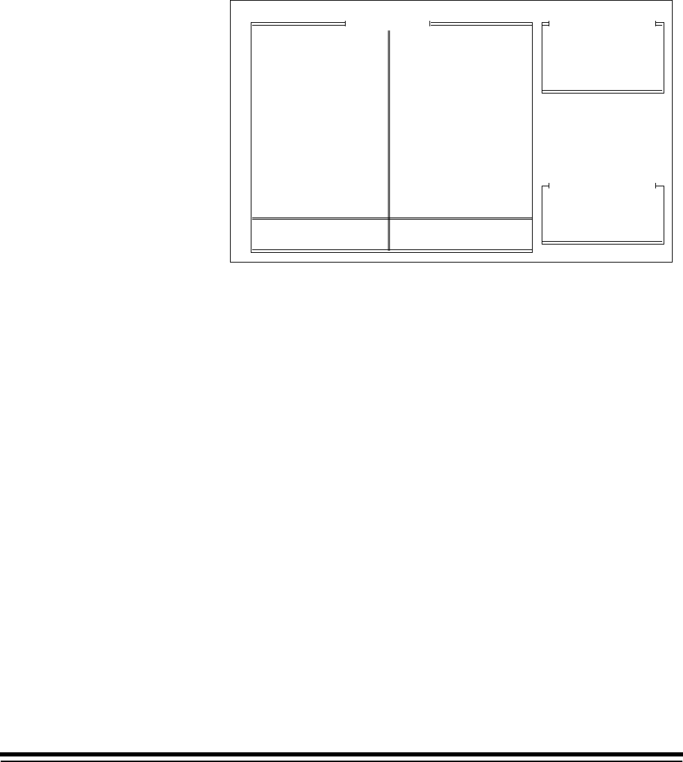
3-42 A-61097 May 1997
Length Error Response
This mode defines the action taken if a document is smaller than the
minimum length specified or larger than the maximum length specified.
The default value is Display and Beep.
■Microimager 70 ■Microimager 70/AFM ■Scanner 900
■Scanner 923 ■Scanner/Microimager 990 ■Scanner 9500
1. Select Length Err Response.
Display
Display and Beep
Stop and Display
Previous Menu
Len Chk Error Response
Status
Max Document Length
Min Document Length
Length Err Response
Previous Menu
Mode Configuration
Don't Save & End Session
End Configuration
Save & End Session
Previous Menu
Mode Number: 10 Mode Name: MODE10
Length Monitor
MODE 10
3 Lvl
Supprs
4233
2112
None
Auto
Duplex
?????
1 Roll
Comic
Off
Off
Off
Xport
Off
Undef
Undef
Off
Off
Off
Lvl 2
Off
N N N
Off
On
Disply
Off
Off
Off
Off
No Sav
F
Mode Name
Index Format
IA Display Format
IA Field Widths
Level Rules
Batching
AEC Mode
Film Mode
Reduction Ratio
# of Cassettes
Film Writer
Image Mgmt Code
Length Monitor
Skew Monitor
Check Stacker
Endorser
Not Used
Ftswitch Pressed
Ftswitch Released
Ftswitch Cnf Tone
Patch Reader 1
Patch Reader 2
Patch Definition
Bar Code
Confirmation Tone
OCR Status
COIN User Channel
Printer Control
Primary DP-1
Secondary DP-1
Doc. Printer 12
Document Sorter
Mode Overrides
Film Definition
2. Select the desired error response action.
A-61097 May 1997 3-43
Skew Monitor
■Microimager 70 ■Microimager 70/AFM ■Scanner 900
■Scanner 923 ■Scanner/Microimager 990 ■Scanner 9500
NOTE: The Advanced Document Controller must be installed.
1. Select Skew Monitor.
Skew Detect Status
Skew Threshold
Skew Error Response
Previous Menu
Mode Configuration
Don't Save & End Session
End Configuration
Save & End Session
Previous Menu
Mode Number: 10 Mode Name: MODE10
Skew Monitor
MODE 10
3 Lvl
Supprs
4233
2112
None
Auto
Duplex
?????
1 Roll
Comic
Off
Off
Off
Xport
Off
Undef
Undef
Off
Off
Off
Lvl 2
Off
N N N
Off
On
Disply
Off
Off
Off
Off
No Sav
F
Mode Name
Index Format
IA Display Format
IA Field Widths
Level Rules
Batching
AEC Mode
Film Mode
Reduction Ratio
# of Cassettes
Film Writer
Image Mgmt Code
Length Monitor
Skew Monitor
Check Stacker
Endorser
Not Used
Ftswitch Pressed
Ftswitch Released
Ftswitch Cnf Tone
Patch Reader 1
Patch Reader 2
Patch Definition
Bar Code
Confirmation Tone
OCR Status
COIN User Channel
Printer Control
Primary DP-1
Secondary DP-1
Doc. Printer 12
Document Sorter
Mode Overrides
Film Definition
Skew Detect Status
Enables or disables skew detection. The default value is Off or Disabled.
■Microimager 70 ■Microimager 70/AFM ■Scanner 900
■Scanner 923 ■Scanner/Microimager 990 ■Scanner 9500
1. Select Skew Detect Status.
Skew Monitor
Mode Configuration
Don't Save & End Session
End Configuration
Save & End Session
Previous Menu
Mode Number: 10 Mode Name: MODE10
Off or Disabled
On or Enabled
Previous Menu
FieldSkew Status
Skew Detect Status
Skew Threshold
Skew Error Response
Previous Menu
MODE 10
3 Lvl
Supprs
4233
2112
None
Auto
Duplex
?????
1 Roll
Comic
Off
Off
Off
Xport
Off
Undef
Undef
Off
Off
Off
Lvl 2
Off
N N N
Off
On
Disply
Off
Off
Off
Off
No Sav
F
Mode Name
Index Format
IA Display Format
IA Field Widths
Level Rules
Batching
AEC Mode
Film Mode
Reduction Ratio
# of Cassettes
Film Writer
Image Mgmt Code
Length Monitor
Skew Monitor
Check Stacker
Endorser
Not Used
Ftswitch Pressed
Ftswitch Released
Ftswitch Cnf Tone
Patch Reader 1
Patch Reader 2
Patch Definition
Bar Code
Confirmation Tone
OCR Status
COIN User Channel
Printer Control
Primary DP-1
Secondary DP-1
Doc. Printer 12
Document Sorter
Mode Overrides
Film Definition
2. Select the desired status.
NOTE: If Off or Disabled is selected, definitions for the remaining options
will be ignored.

3-44 A-61097 May 1997
Skew Threshold
This mode defines the amount of tolerable skew. If 5 Degrees is selected,
an error will be reported if the amount of document skew is between 5 and
30 degrees. If 10 Degrees is selected, an error will be reported if the
amount of document skew is between 10 and 30 degrees. Regardless
of the option selected, if the amount of document skew is greater than
30 degrees, no error will be reported. The default value is 10 Degrees.
■Microimager 70 ■Microimager 70/AFM ■Scanner 900
■Scanner 923 ■Scanner/Microimager 990 ■Scanner 9500
1. Select Skew Threshold.
Skew Monitor
Mode Configuration
Don't Save & End Session
End Configuration
Save & End Session
Previous Menu
Mode Number: 10 Mode Name: MODE10
5 Degrees
10 Degrees
Previous Menu
FieldSkew Threshold
Skew Detect Status
Skew Threshold
Skew Error Response
Previous Menu
MODE 10
3 Lvl
Supprs
4233
2112
None
Auto
Duplex
?????
1 Roll
Comic
Off
Off
Off
Xport
Off
Undef
Undef
Off
Off
Off
Lvl 2
Off
N N N
Off
On
Disply
Off
Off
Off
Off
No Sav
F
Mode Name
Index Format
IA Display Format
IA Field Widths
Level Rules
Batching
AEC Mode
Film Mode
Reduction Ratio
# of Cassettes
Film Writer
Image Mgmt Code
Length Monitor
Skew Monitor
Check Stacker
Endorser
Not Used
Ftswitch Pressed
Ftswitch Released
Ftswitch Cnf Tone
Patch Reader 1
Patch Reader 2
Patch Definition
Bar Code
Confirmation Tone
OCR Status
COIN User Channel
Printer Control
Primary DP-1
Secondary DP-1
Doc. Printer 12
Document Sorter
Mode Overrides
Film Definition
2. Select the desired threshold.
A-61097 May 1997 3-45
Skew Error Response
This mode defines the action taken if the amount of document skew is
greater than the threshold specified. The default value is Display and
Beep.
■Microimager 70 ■Microimager 70/AFM ■Scanner 900
■Scanner 923 ■Scanner/Microimager 990 ■Scanner 9500
1. Select Skew Err Response.
Skewed Error Response
Display
Display and Beep
Stop and Display
Previous Menu
Skew Monitor
Mode Configuration
Don't Save & End Session
End Configuration
Save & End Session
Previous Menu
Mode Number: 10 Mode Name: MODE10
Skew Detect Status
Skew Threshold
Skew Error Response
Previous Menu
MODE 10
3 Lvl
Supprs
4233
2112
None
Auto
Duplex
?????
1 Roll
Comic
Off
Off
Off
Xport
Off
Undef
Undef
Off
Off
Off
Lvl 2
Off
N N N
Off
On
Disply
Off
Off
Off
Off
No Sav
F
Mode Name
Index Format
IA Display Format
IA Field Widths
Level Rules
Batching
AEC Mode
Film Mode
Reduction Ratio
# of Cassettes
Film Writer
Image Mgmt Code
Length Monitor
Skew Monitor
Check Stacker
Endorser
Not Used
Ftswitch Pressed
Ftswitch Released
Ftswitch Cnf Tone
Patch Reader 1
Patch Reader 2
Patch Definition
Bar Code
Confirmation Tone
OCR Status
COIN User Channel
Printer Control
Primary DP-1
Secondary DP-1
Doc. Printer 12
Document Sorter
Mode Overrides
Film Definition
2. Select the desired error response action.
3-46 A-61097 May 1997
Check Stacker
NOTE: The Check Stacker must be installed.
This mode defines when the check stacker is activated. Continuous will
activate the check stacker whenever the side panel switch is on.
Documents in Transport will activate the check stacker only when there
are documents exiting the transport. The default value is Documents in
Transport.
■Microimager 70 ■Microimager 70/AFM ■Scanner 900
■Scanner 923 ■Scanner/Microimager 990 ■Scanner 9500
1. Select Check Stacker.
Continuous
Documents in Transport
Previous Menu
Mode Configuration
Don't Save & End Session
End Configuration
Save & End Session
Previous Menu
Mode Number: 10 Mode Name: MODE10
Check Stacker
MODE 10
3 Lvl
Supprs
4233
2112
None
Auto
Duplex
?????
1 Roll
Comic
Off
Off
Off
Xport
Off
Undef
Undef
Off
Off
Off
Lvl 2
Off
N N N
Off
On
Disply
Off
Off
Off
Off
No Sav
F
Mode Name
Index Format
IA Display Format
IA Field Widths
Level Rules
Batching
AEC Mode
Film Mode
Reduction Ratio
# of Cassettes
Film Writer
Image Mgmt Code
Length Monitor
Skew Monitor
Check Stacker
Endorser
Not Used
Ftswitch Pressed
Ftswitch Released
Ftswitch Cnf Tone
Patch Reader 1
Patch Reader 2
Patch Definition
Bar Code
Confirmation Tone
OCR Status
COIN User Channel
Printer Control
Primary DP-1
Secondary DP-1
Doc. Printer 12
Document Sorter
Mode Overrides
Film Definition
2. Select the desired option.

A-61097 May 1997 3-47
Endorser
NOTE: The Endorser must be installed.
■Microimager 70 ■Microimager 70/AFM ■Scanner 900
■Scanner 923 ■Scanner/Microimager 990 ■Scanner 9500
1. Select Endorser.
Status
Mode
Print Position
Previous Menu
Mode Configuration
Don't Save & End Session
End Configuration
Save & End Session
Previous Menu
Mode Number: 10 Mode Name: MODE10
Endorser
MODE 10
3 Lvl
Supprs
4233
2112
None
Auto
Duplex
?????
1 Roll
Comic
Off
Off
Off
Xport
Off
Undef
Undef
Off
Off
Off
Lvl 2
Off
N N N
Off
On
Disply
Off
Off
Off
Off
No Sav
F
Mode Name
Index Format
IA Display Format
IA Field Widths
Level Rules
Batching
AEC Mode
Film Mode
Reduction Ratio
# of Cassettes
Film Writer
Image Mgmt Code
Length Monitor
Skew Monitor
Check Stacker
Endorser
Not Used
Ftswitch Pressed
Ftswitch Released
Ftswitch Cnf Tone
Patch Reader 1
Patch Reader 2
Patch Definition
Bar Code
Confirmation Tone
OCR Status
COIN User Channel
Printer Control
Primary DP-1
Secondary DP-1
Doc. Printer 12
Document Sorter
Mode Overrides
Film Definition
3-48 A-61097 May 1997
Endorser Status
Enables or disables the endorser. The default value is Off or Disabled.
■Microimager 70 ■Microimager 70/AFM ■Scanner 900
■Scanner 923 ■Scanner/Microimager 990 ■Scanner 9500
1. Select Status.
Status
Mode
Print Position
Previous Menu
Mode Configuration
Don't Save & End Session
End Configuration
Save & End Session
Previous Menu
Mode Number: 10 Mode Name: MODE10
Endorser
Off or Disabled
On or Enabled
Previous Menu
FieldEndorser Status
MODE 10
3 Lvl
Supprs
4233
2112
None
Auto
Duplex
?????
1 Roll
Comic
Off
Off
Off
Xport
Off
Undef
Undef
Off
Off
Off
Lvl 2
Off
N N N
Off
On
Disply
Off
Off
Off
Off
No Sav
F
Mode Name
Index Format
IA Display Format
IA Field Widths
Level Rules
Batching
AEC Mode
Film Mode
Reduction Ratio
# of Cassettes
Film Writer
Image Mgmt Code
Length Monitor
Skew Monitor
Check Stacker
Endorser
Not Used
Ftswitch Pressed
Ftswitch Released
Ftswitch Cnf Tone
Patch Reader 1
Patch Reader 2
Patch Definition
Bar Code
Confirmation Tone
OCR Status
COIN User Channel
Printer Control
Primary DP-1
Secondary DP-1
Doc. Printer 12
Document Sorter
Mode Overrides
Film Definition
2. Select the desired status.
NOTE: If Off or Disabled is selected, definitions for the remaining options
will be ignored.
A-61097 May 1997 3-49
Endorser Mode
This mode defines whether the endorser will print continually or only once
per document. Continuous will activate the Endorser continually. Single
Stamp will activate the Endorser only once per document. The default
value is Continuous.
■Microimager 70 ■Microimager 70/AFM ■Scanner 900
■Scanner 923 ■Scanner/Microimager 990 ■Scanner 9500
1. Select Mode.
Status
Mode
Print Position
Previous Menu
Mode Configuration
Don't Save & End Session
End Configuration
Save & End Session
Previous Menu
Mode Number: 10 Mode Name: MODE10
Endorser
Continuous
Single Stamp
Previous Menu
FieldEndorser Mode
MODE 10
3 Lvl
Supprs
4233
2112
None
Auto
Duplex
?????
1 Roll
Comic
Off
Off
Off
Xport
Off
Undef
Undef
Off
Off
Off
Lvl 2
Off
N N N
Off
On
Disply
Off
Off
Off
Off
No Sav
F
Mode Name
Index Format
IA Display Format
IA Field Widths
Level Rules
Batching
AEC Mode
Film Mode
Reduction Ratio
# of Cassettes
Film Writer
Image Mgmt Code
Length Monitor
Skew Monitor
Check Stacker
Endorser
Not Used
Ftswitch Pressed
Ftswitch Released
Ftswitch Cnf Tone
Patch Reader 1
Patch Reader 2
Patch Definition
Bar Code
Confirmation Tone
OCR Status
COIN User Channel
Printer Control
Primary DP-1
Secondary DP-1
Doc. Printer 12
Document Sorter
Mode Overrides
Film Definition
2. Select the desired mode.

3-50 A-61097 May 1997
Endorser Print Position
This mode defines how far from the leading edge of the document the
endorsement will appear: The default value is 0000.250 inch/
6.350 mm.
■Microimager 70 ■Microimager 70/AFM ■Scanner 900
■Scanner 923 ■Scanner/Microimager 990 ■Scanner 9500
1. Select Print Position.
Status
Mode
Print Position
Previous Menu
Mode Configuration
Don't Save & End Session
End Configuration
Save & End Session
Previous Menu
Mode Number: 10 Mode Name: MODE10
Endorser
Enter Print Position
0000.250
Range: 0.00 - 70.00
MODE 10
3 Lvl
Supprs
4233
2112
None
Auto
Duplex
?????
1 Roll
Comic
Off
Off
Off
Xport
Off
Undef
Undef
Off
Off
Off
Lvl 2
Off
N N N
Off
On
Disply
Off
Off
Off
Off
No Sav
F
Mode Name
Index Format
IA Display Format
IA Field Widths
Level Rules
Batching
AEC Mode
Film Mode
Reduction Ratio
# of Cassettes
Film Writer
Image Mgmt Code
Length Monitor
Skew Monitor
Check Stacker
Endorser
Not Used
Ftswitch Pressed
Ftswitch Released
Ftswitch Cnf Tone
Patch Reader 1
Patch Reader 2
Patch Definition
Bar Code
Confirmation Tone
OCR Status
COIN User Channel
Printer Control
Primary DP-1
Secondary DP-1
Doc. Printer 12
Document Sorter
Mode Overrides
Film Definition
2. Enter the desired print position within the allowable range for your
machine type.
— Microimager 70—0 to 70 inches or 0 to 1778 mm.
— Scanner 900—0 to 20 inches or 0 to 500 mm.
— Scanner 923—0 to 20 inches or 0 to 500 mm.
— Scanner 9500—0 to 20 inches or 0 to 500 mm.
— Scanner/Microimager 990—0 to 20 inches or
0 to 500 mm.
Not Used
This mode is not selectable. It is for future use only.

A-61097 May 1997 3-51
Footswitch Pressed
NOTE: The Footswitch accessory must be installed.
This mode defines the action which results when the footswitch is
pressed. The default is Undefined.
■Microimager 70 ■Microimager 70/AFM ■Scanner 900
■Scanner 923 ■Scanner/Microimager 990 ■Scanner 9500
When using a Microimager 70 without the Advanced Function Module
installed, a limited number of actions are available. The available actions
are:
• Undefined
• Level 0
• Level 1
• Level 2
• Level 3
• Increment
When using a Microimager 70 with the Advanced Function Module
installed, Scanner 900, Scanner 923, Scanner 9500, or Scanner/
Microimager 990, all of the actions listed are available.
1. Select Ftswitch Pressed.
Undefined
Level 0
Level 1
Level 2
Level 3
Increment
Sustained Level 0
Sustained Level 1
Sustained Level 2
Sustained Level 3
Function Key
P-Key
Previous Menu
Mode Configuration
Don't Save & End Session
End Configuration
Save & End Session
Previous Menu
Mode Number: 10 Mode Name: MODE10
Footswitch Pressed
MODE 10
3 Lvl
Supprs
4233
2112
None
Auto
Duplex
?????
1 Roll
Comic
Off
Off
Off
Xport
Off
Undef
Undef
Off
Off
Off
Lvl 2
Off
N N N
Off
On
Disply
Off
Off
Off
Off
No Sav
F
Mode Name
Index Format
IA Display Format
IA Field Widths
Level Rules
Batching
AEC Mode
Film Mode
Reduction Ratio
# of Cassettes
Film Writer
Image Mgmt Code
Length Monitor
Skew Monitor
Check Stacker
Endorser
Not Used
Ftswitch Pressed
Ftswitch Released
Ftswitch Cnf Tone
Patch Reader 1
Patch Reader 2
Patch Definition
Bar Code
Confirmation Tone
OCR Status
COIN User Channel
Printer Control
Primary DP-1
Secondary DP-1
Doc. Printer 12
Document Sorter
Mode Overrides
Film Definition
2. Select the desired action.
NOTE: When Footswitch Pressed is set to undefined, F/S Released
cannot be set.

3-52 A-61097 May 1997
Footswitch Released
NOTE: The Footswitch accessory must be installed.
This mode defines the action which results when the footswitch is
pressed. The default is Undefined.
■Microimager 70 ■Microimager 70/AFM ■Scanner 900
■Scanner 923 ■Scanner/Microimager 990 ■Scanner 9500
1. Select Ftswitch Pressed.
Undefined
Level 0
Level 1
Level 2
Level 3
Previous Menu
Mode Configuration
Don't Save & End Session
End Configuration
Save & End Session
Previous Menu
Mode Number: 10 Mode Name: MODE10
FS Released
MODE 10
3 Lvl
Supprs
4233
2112
None
Auto
Duplex
?????
1 Roll
Comic
Off
Off
Off
Xport
Off
Undef
Undef
Off
Off
Off
Lvl 2
Off
N N N
Off
On
Disply
Off
Off
Off
Off
No Sav
F
Mode Name
Index Format
IA Display Format
IA Field Widths
Level Rules
Batching
AEC Mode
Film Mode
Reduction Ratio
# of Cassettes
Film Writer
Image Mgmt Code
Length Monitor
Skew Monitor
Check Stacker
Endorser
Not Used
Ftswitch Pressed
Ftswitch Released
Ftswitch Cnf Tone
Patch Reader 1
Patch Reader 2
Patch Definition
Bar Code
Confirmation Tone
OCR Status
COIN User Channel
Printer Control
Primary DP-1
Secondary DP-1
Doc. Printer 12
Document Sorter
Mode Overrides
Film Definition
2. Select the desired action.
A-61097 May 1997 3-53
Footswitch Confirmation Tone
NOTE: The Footswitch accessory must be installed.
This mode enables or disables the footswitch press confirmation tone. The
default is Off or Disabled.
❏Microimager 70 ■Microimager 70/AFM ■Scanner 900
■Scanner 923 ■Scanner/Microimager 990 ■Scanner 9500
1. Select Ftswitch Cnf Tone.
Mode Configuration
Don't Save & End Session
End Configuration
Save & End Session
Previous Menu
Mode Number: 10 Mode Name: MODE10
Off or Disabled
On or Enabled
Previous Menu
FieldFt Switch Tone
MODE 10
3 Lvl
Supprs
4233
2112
None
Auto
Duplex
?????
1 Roll
Comic
Off
Off
Off
Xport
Off
Undef
Undef
Off
Off
Off
Lvl 2
Off
N N N
Off
On
Disply
Off
Off
Off
Off
No Sav
F
Mode Name
Index Format
IA Display Format
IA Field Widths
Level Rules
Batching
AEC Mode
Film Mode
Reduction Ratio
# of Cassettes
Film Writer
Image Mgmt Code
Length Monitor
Skew Monitor
Check Stacker
Endorser
Not Used
Ftswitch Pressed
Ftswitch Released
Ftswitch Cnf Tone
Patch Reader 1
Patch Reader 2
Patch Definition
Bar Code
Confirmation Tone
OCR Status
COIN User Channel
Printer Control
Primary DP-1
Secondary DP-1
Doc. Printer 12
Document Sorter
Mode Overrides
Film Definition
2. Select the desired action.
NOTE: A confirmation tone is issued only when the footswitch is pressed,
not when a footswitch is released.
3-54 A-61097 May 1997
Patch Reader 1
NOTE: A Patch Reader accessory or Document Scanning Array must be
installed.
Enables or disables the primary patch reader. The default value is Off or
Disabled.
■Microimager 70 ■Microimager 70/AFM ■Scanner 900
■Scanner 923 ■Scanner/Microimager 990 ■Scanner 9500
1. Select Patch Reader 1.
Mode Configuration
Don't Save & End Session
End Configuration
Save & End Session
Previous Menu
Mode Number: 10 Mode Name: MODE10
Off or Disabled
On or Enabled
Previous Menu
FieldPatch 1 Status
Units with Patch Reader
MODE 10
3 Lvl
Supprs
4233
2112
None
Auto
Duplex
?????
1 Roll
Comic
Off
Off
Off
Xport
Off
Undef
Undef
Off
Off
Off
Lvl 2
Off
N N N
Off
On
Disply
Off
Off
Off
Off
No Sav
F
Mode Name
Index Format
IA Display Format
IA Field Widths
Level Rules
Batching
AEC Mode
Film Mode
Reduction Ratio
# of Cassettes
Film Writer
Image Mgmt Code
Length Monitor
Skew Monitor
Check Stacker
Endorser
Not Used
Ftswitch Pressed
Ftswitch Released
Ftswitch Cnf Tone
Patch Reader 1
Patch Reader 2
Patch Definition
Bar Code
Confirmation Tone
OCR Status
COIN User Channel
Printer Control
Primary DP-1
Secondary DP-1
Doc. Printer 12
Document Sorter
Mode Overrides
Film Definition
2. Select the desired status.
NOTE: IF Off or Disabled is selected, the definitions for the remaining
patch options will be ignored.
If you have a unit with Document Scanning Array (DSA) and you
choose Patch Reader 1 you will get the message: Patch Reader
1: the accessory that you requested is not installed. This is due to
the fact that Patch Reading must be set up under barcode if you
have a DSA.
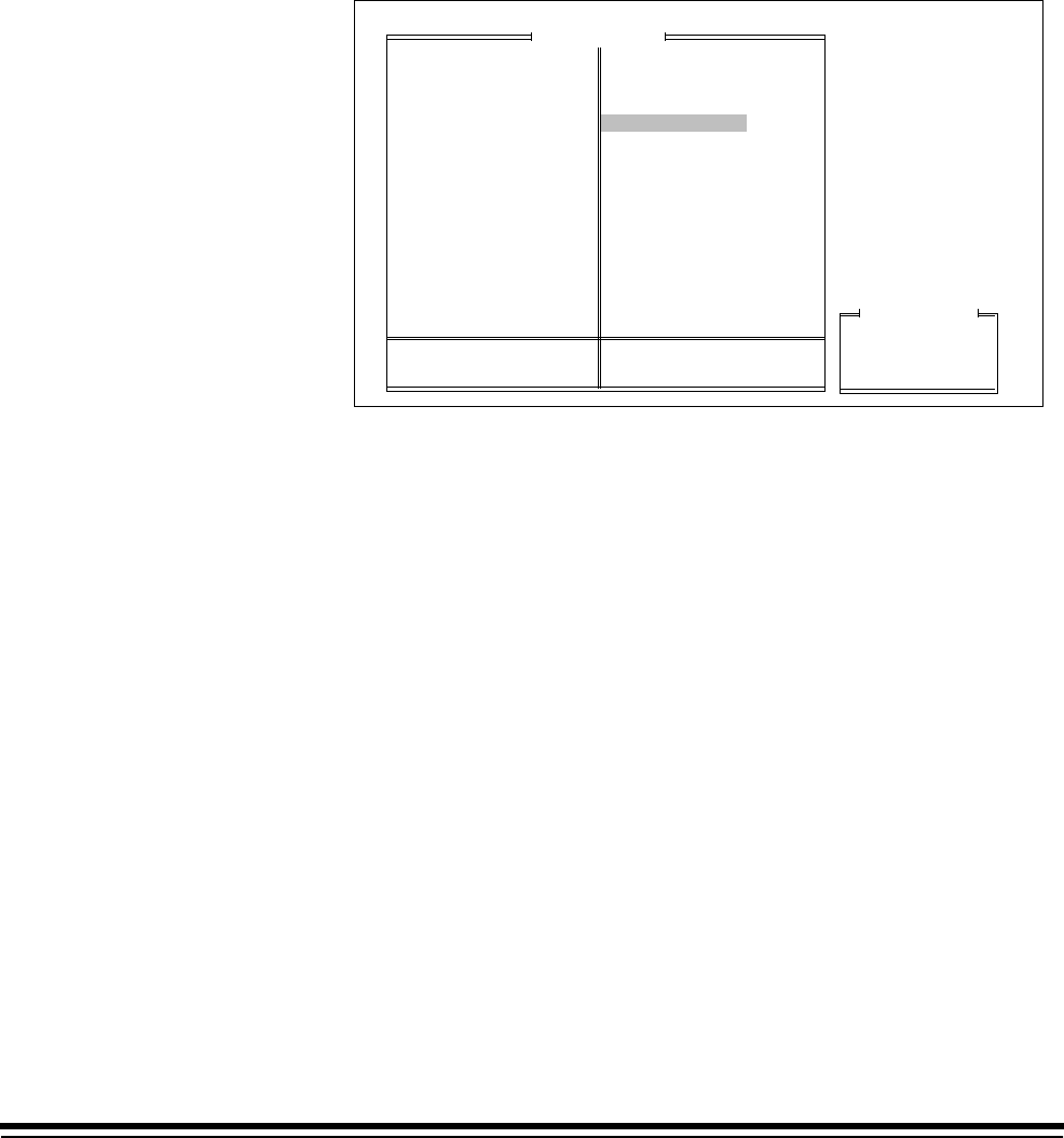
A-61097 May 1997 3-55
Patch Reader 2
NOTE: A Patch Reader accessories or Document Scanning Array must
be installed.
Enables or disables the secondary patch reader. The default value is Off
or Disabled.
❏Microimager 70 ■Microimager 70/AFM ■Scanner 900
■Scanner 923 ❏Scanner/Microimager 990 ■Scanner 9500
1. Select Patch Reader 2.
Mode Configuration
Don't Save & End Session
End Configuration
Save & End Session
Previous Menu
Mode Number: 10 Mode Name: MODE10
Off or Disabled
On or Enabled
Previous Menu
FieldPatch 2 Status
MODE 10
3 Lvl
Supprs
4233
2112
None
Auto
Duplex
?????
1 Roll
Comic
Off
Off
Off
Xport
Off
Undef
Undef
Off
Off
Off
Lvl 2
Off
N N N
Off
On
Disply
Off
Off
Off
Off
No Sav
F
Mode Name
Index Format
IA Display Format
IA Field Widths
Level Rules
Batching
AEC Mode
Film Mode
Reduction Ratio
# of Cassettes
Film Writer
Image Mgmt Code
Length Monitor
Skew Monitor
Check Stacker
Endorser
Not Used
Ftswitch Pressed
Ftswitch Released
Ftswitch Cnf Tone
Patch Reader 1
Patch Reader 2
Patch Definition
Bar Code
Confirmation Tone
OCR Status
COIN User Channel
Printer Control
Primary DP-1
Secondary DP-1
Doc. Printer 12
Document Sorter
Mode Overrides
Film Definition
2. Select the desired status.
NOTE: IF Off or Disabled is selected, the definitions for the remaining
patch options will be ignored.
If you have a DSA, this option is not available.

3-56 A-61097 May 1997
Patch Definition
NOTE: At least one Patch Reader accessory or Document Scanning
Array must be installed.
■Microimager 70 ■Microimager 70/AFM ■Scanner 900
■Scanner 923 ■Scanner/Microimager 990 ■Scanner 9500
1. Select Patch Definition.
Mode Configuration
Don't Save & End Session
End Configuration
Save & End Session
Previous Menu
Mode Number: 10 Mode Name: MODE10
Patch Definition
MODE 10
3 Lvl
Supprs
4233
2112
None
Auto
Duplex
?????
1 Roll
Comic
Off
Off
Off
Xport
Off
Undef
Undef
Off
Off
Off
Lvl 2
Off
N N N
Off
On
Disply
Off
Off
Off
Off
No Sav
F
Mode Name
Index Format
IA Display Format
IA Field Widths
Level Rules
Batching
AEC Mode
Film Mode
Reduction Ratio
# of Cassettes
Film Writer
Image Mgmt Code
Length Monitor
Skew Monitor
Check Stacker
Endorser
Not Used
Ftswitch Pressed
Ftswitch Released
Ftswitch Cnf Tone
Patch Reader 1
Patch Reader 2
Patch Definition
Bar Code
Confirmation Tone
OCR Status
COIN User Channel
Printer Control
Primary DP-1
Secondary DP-1
Doc. Printer 12
Document Sorter
Mode Overrides
Film Definition
Transfer Patch Definition
Film Transfer Patches
Patch Recognition
Previous Menu

A-61097 May 1997 3-57
Transfer Patch Definition
This mode defines which level should be assigned to the next document
when a transfer patch is used. The default value is Level 2.
■Microimager 70 ■Microimager 70/AFM ■Scanner 900
■Scanner 923 ■Scanner/Microimager 990 ■Scanner 9500
1. Select Transfer Patch Definition.
Mode Configuration
Don't Save & End Session
End Configuration
Save & End Session
Previous Menu
Mode Number: 10 Mode Name: MODE10
Patch Definition
FieldPatch Field
MODE 10
3 Lvl
Supprs
4233
2112
None
Auto
Duplex
?????
1 Roll
Comic
Off
Off
Off
Xport
Off
Undef
Undef
Off
Off
Off
Lvl 2
Off
N N N
Off
On
Disply
Off
Off
Off
Off
No Sav
F
Mode Name
Index Format
IA Display Format
IA Field Widths
Level Rules
Batching
AEC Mode
Film Mode
Reduction Ratio
# of Cassettes
Film Writer
Image Mgmt Code
Length Monitor
Skew Monitor
Check Stacker
Endorser
Not Used
Ftswitch Pressed
Ftswitch Released
Ftswitch Cnf Tone
Patch Reader 1
Patch Reader 2
Patch Definition
Bar Code
Confirmation Tone
OCR Status
COIN User Channel
Printer Control
Primary DP-1
Secondary DP-1
Doc. Printer 12
Document Sorter
Mode Overrides
Film Definition
Transfer Patch Definition
Film Transfer Patches
Patch Recognition
Previous Menu
Level 1
Level 2
Level 3
None
Previous Menu
2. Select the desired level.

3-58 A-61097 May 1997
Film Transfer Patches
This mode defines whether or not a document containing a transfer patch
is to be filmed. The default value is Transfer Patch Filmed.
❏Microimager 70 ■Microimager 70/AFM ❏Scanner 900
❏Scanner 923 ■Scanner/Microimager 990 ❏Scanner 9500
1. Select Film Transfer Patches.
Mode Configuration
Don't Save & End Session
End Configuration
Save & End Session
Previous Menu
Mode Number: 10 Mode Name: MODE10
Patch Definition
FieldTransfer Patch
MODE 10
3 Lvl
Supprs
4233
2112
None
Auto
Duplex
?????
1 Roll
Comic
Off
Off
Off
Xport
Off
Undef
Undef
Off
Off
Off
Lvl 2
Off
N N N
Off
On
Disply
Off
Off
Off
Off
No Sav
F
Mode Name
Index Format
IA Display Format
IA Field Widths
Level Rules
Batching
AEC Mode
Film Mode
Reduction Ratio
# of Cassettes
Film Writer
Image Mgmt Code
Length Monitor
Skew Monitor
Check Stacker
Endorser
Not Used
Ftswitch Pressed
Ftswitch Released
Ftswitch Cnf Tone
Patch Reader 1
Patch Reader 2
Patch Definition
Bar Code
Confirmation Tone
OCR Status
COIN User Channel
Printer Control
Primary DP-1
Secondary DP-1
Doc. Printer 12
Document Sorter
Mode Overrides
Film Definition
Transfer Patch Definition
Film Transfer Patches
Patch Recognition
Previous Menu
Xfer Patch NOT Filmed
Xfer Patch Filmed
Previous Menu
2. Select the desired option.
NOTE: This selection is not available on the scanners.
A-61097 May 1997 3-59
Patch Recognition
This mode defines which patch codes will be recognized by the system.
The default value is 2, 3, & T.
❏Microimager 70 ■Microimager 70/AFM ■Scanner 900
■Scanner 923 ■Scanner/Microimager 990 ■Scanner 9500
1. Select Patch Recognition.
Mode Configuration
Don't Save & End Session
End Configuration
Save & End Session
Previous Menu
Mode Number: 10 Mode Name: MODE10
Patch Definition
Patch Recognition
MODE 10
3 Lvl
Supprs
4233
2112
None
Auto
Duplex
?????
1 Roll
Comic
Off
Off
Off
Xport
Off
Undef
Undef
Off
Off
Off
Lvl 2
Off
N N N
Off
On
Disply
Off
Off
Off
Off
No Sav
F
Mode Name
Index Format
IA Display Format
IA Field Widths
Level Rules
Batching
AEC Mode
Film Mode
Reduction Ratio
# of Cassettes
Film Writer
Image Mgmt Code
Length Monitor
Skew Monitor
Check Stacker
Endorser
Not Used
Ftswitch Pressed
Ftswitch Released
Ftswitch Cnf Tone
Patch Reader 1
Patch Reader 2
Patch Definition
Bar Code
Confirmation Tone
OCR Status
COIN User Channel
Printer Control
Primary DP-1
Secondary DP-1
Doc. Printer 12
Document Sorter
Mode Overrides
Film Definition
Transfer Patch Definition
Film Transfer Patches
Patch Recognition
Previous Menu
Type 2 Patches
Type 3 Patches
Transfer Patches
Type 2 & Type 3 Patches
Type 2 & Transfer Patches
Type 3 & Transfer Patches
Type 2, 3 & Xfer Patches
Previous Menu
2. Select the patch code type(s) to be processed by the system.

3-60 A-61097 May 1997
Bar Code
NOTE: A Bar Code Reader must be installed.
❏Microimager 70 ■Microimager 70/AFM ■Scanner 900
■Scanner 923 ■Scanner/Microimager 990 ■Scanner 9500
1. Select Bar Code.
Mode Configuration
Don't Save & End Session
End Configuration
Save & End Session
Previous Menu
Mode Number: 10 Mode Name: MODE10
Bar Code Reader
MODE 10
3 Lvl
Supprs
4233
2112
None
Auto
Duplex
?????
1 Roll
Comic
Off
Off
Off
Xport
Off
Undef
Undef
Off
Off
Off
Lvl 2
Off
N N N
Off
On
Disply
Off
Off
Off
Off
No Sav
F
Mode Name
Index Format
IA Display Format
IA Field Widths
Level Rules
Batching
AEC Mode
Film Mode
Reduction Ratio
# of Cassettes
Film Writer
Image Mgmt Code
Length Monitor
Skew Monitor
Check Stacker
Endorser
Not Used
Ftswitch Pressed
Ftswitch Released
Ftswitch Cnf Tone
Patch Reader 1
Patch Reader 2
Patch Definition
Bar Code
Confirmation Tone
OCR Status
COIN User Channel
Printer Control
Primary DP-1
Secondary DP-1
Doc. Printer 12
Document Sorter
Mode Overrides
Film Definition
Bar Code Reading Status
Bar Code Type
# of Bar Code Characters
Bar Codes per Document
Distance Between Codes
Scan Direction
Image Processing
Partial Read Enabled
Min. Partial Characters
DSA Patch Reading Status
Patch Horizontal Location
End Fed Patch Read Status
Level Change via Bar Code
Previous Menu
A-61097 May 1997 3-61
Bar Code Reading Status
Enables or disables bar code reading. The default value is Off or
Disabled.
❏Microimager 70 ■Microimager 70/AFM ■Scanner 900
■Scanner 923 ■Scanner/Microimager 990 ■Scanner 9500
1. Select Bar Code Reading Status.
Mode Configuration
Don't Save & End Session
End Configuration
Save & End Session
Previous Menu
Mode Number: 10 Mode Name: MODE10
Bar Code Reader
Field
Bar Code Status
MODE 10
3 Lvl
Supprs
4233
2112
None
Auto
Duplex
?????
1 Roll
Comic
Off
Off
Off
Xport
Off
Undef
Undef
Off
Off
Off
Lvl 2
Off
N N N
Off
On
Disply
Off
Off
Off
Off
No Sav
F
Mode Name
Index Format
IA Display Format
IA Field Widths
Level Rules
Batching
AEC Mode
Film Mode
Reduction Ratio
# of Cassettes
Film Writer
Image Mgmt Code
Length Monitor
Skew Monitor
Check Stacker
Endorser
Not Used
Ftswitch Pressed
Ftswitch Released
Ftswitch Cnf Tone
Patch Reader 1
Patch Reader 2
Patch Definition
Bar Code
Confirmation Tone
OCR Status
COIN User Channel
Printer Control
Primary DP-1
Secondary DP-1
Doc. Printer 12
Document Sorter
Mode Overrides
Film Definition
Off or Disabled
On or Enabled
Previous Menu
Bar Code Reading Status
Bar Code Type
# of Bar Code Characters
Bar Codes per Document
Distance Between Codes
Scan Direction
Image Processing
Partial Read Enabled
Min. Partial Characters
DSA Patch Reading Status
Patch Horizontal Location
End Fed Patch Read Status
Level Change via Bar Code
Previous Menu
2. Select the desired status.
NOTE: If Off or Disabled is selected, definitions for the remaining bar
code options will be ignored.

3-62 A-61097 May 1997
Bar Code Type
Identifies the type of bar code which is to be read. The default value is
Code 39.
❏Microimager 70 ■Microimager 70/AFM ■Scanner 900
■Scanner 923 ■Scanner/Microimager 990 ■Scanner 9500
1. Select Bar Code Type.
Mode Configuration
Don't Save & End Session
End Configuration
Save & End Session
Previous Menu
Mode Number: 10 Mode Name: MODE10
Bar Code Reader
FieldBar Code Type
MODE 10
3 Lvl
Supprs
4233
2112
None
Auto
Duplex
?????
1 Roll
Comic
Off
Off
Off
Xport
Off
Undef
Undef
Off
Off
Off
Lvl 2
Off
N N N
Off
On
Disply
Off
Off
Off
Off
No Sav
F
Mode Name
Index Format
IA Display Format
IA Field Widths
Level Rules
Batching
AEC Mode
Film Mode
Reduction Ratio
# of Cassettes
Film Writer
Image Mgmt Code
Length Monitor
Skew Monitor
Check Stacker
Endorser
Not Used
Ftswitch Pressed
Ftswitch Released
Ftswitch Cnf Tone
Patch Reader 1
Patch Reader 2
Patch Definition
Bar Code
Confirmation Tone
OCR Status
COIN User Channel
Printer Control
Primary DP-1
Secondary DP-1
Doc. Printer 12
Document Sorter
Mode Overrides
Film Definition
Code 39
Interleaved 2/5
Codabar
Previous Menu
Bar Code Reading Status
Bar Code Type
# of Bar Code Characters
Bar Codes per Document
Distance Between Codes
Scan Direction
Image Processing
Partial Read Enabled
Min. Partial Characters
DSA Patch Reading Status
Patch Horizontal Location
End Fed Patch Read Status
Level Change via Bar Code
Previous Menu
2. Select the desired bar code type.
NOTE: Only one type of bar code may be read using a given mode.
However, different modes may be defined as reading different
types of bar code.

A-61097 May 1997 3-63
Number of Bar Code Characters
This mode defines the minimum bar code length allowed (in terms of the
number of characters encoded). The default value is 3.
❏Microimager 70 ■Microimager 70/AFM ■Scanner 900
■Scanner 923 ■Scanner/Microimager 990 ■Scanner 9500
1. Select # of Bar Code Characters.
Mode Configuration
Don't Save & End Session
End Configuration
Save & End Session
Previous Menu
Mode Number: 10 Mode Name: MODE10
Bar Code Reading Status
Bar Code Type
# of Bar Code Characters
Bar Codes per Document
Distance Between Codes
Scan Direction
Image Processing
Partial Read Enabled
Min. Partial Characters
DSA Patch Reading Status
Patch Horizontal Location
End Fed Patch Read Status
Level Change via Bar Code
Previous Menu
Bar Code Reader
Enter Minumum Length
Range: 03 - 80 Characters
03
MODE 10
3 Lvl
Supprs
4233
2112
None
Auto
Duplex
?????
1 Roll
Comic
Off
Off
Off
Xport
Off
Undef
Undef
Off
Off
Off
Lvl 2
Off
N N N
Off
On
Disply
Off
Off
Off
Off
No Sav
F
Mode Name
Index Format
IA Display Format
IA Field Widths
Level Rules
Batching
AEC Mode
Film Mode
Reduction Ratio
# of Cassettes
Film Writer
Image Mgmt Code
Length Monitor
Skew Monitor
Check Stacker
Endorser
Not Used
Ftswitch Pressed
Ftswitch Released
Ftswitch Cnf Tone
Patch Reader 1
Patch Reader 2
Patch Definition
Bar Code
Confirmation Tone
OCR Status
COIN User Channel
Printer Control
Primary DP-1
Secondary DP-1
Doc. Printer 12
Document Sorter
Mode Overrides
Film Definition
2. Select the desired minimum length within the range 3 - 80.
3-64 A-61097 May 1997
Bar Codes per Document
This mode defines the number of bar codes per document to be decoded.
The default value is One Code.
❏Microimager 70 ■Microimager 70/AFM ■Scanner 900
■Scanner 923 ■Scanner/Microimager 990 ■Scanner 9500
1. Select Bar Codes per Document.
Mode Configuration
Don't Save & End Session
End Configuration
Save & End Session
Previous Menu
Mode Number: 10 Mode Name: MODE10
Bar Code Reader
FieldDocument Codes
MODE 10
3 Lvl
Supprs
4233
2112
None
Auto
Duplex
?????
1 Roll
Comic
Off
Off
Off
Xport
Off
Undef
Undef
Off
Off
Off
Lvl 2
Off
N N N
Off
On
Disply
Off
Off
Off
Off
No Sav
F
Mode Name
Index Format
IA Display Format
IA Field Widths
Level Rules
Batching
AEC Mode
Film Mode
Reduction Ratio
# of Cassettes
Film Writer
Image Mgmt Code
Length Monitor
Skew Monitor
Check Stacker
Endorser
Not Used
Ftswitch Pressed
Ftswitch Released
Ftswitch Cnf Tone
Patch Reader 1
Patch Reader 2
Patch Definition
Bar Code
Confirmation Tone
OCR Status
COIN User Channel
Printer Control
Primary DP-1
Secondary DP-1
Doc. Printer 12
Document Sorter
Mode Overrides
Film Definition
Bar Code Reading Status
Bar Code Type
# of Bar Code Characters
Bar Codes per Document
Distance Between Codes
Scan Direction
Image Processing
Partial Read Enabled
Min. Partial Characters
DSA Patch Reading Status
Patch Horizontal Location
End Fed Patch Read Status
Level Change via Bar Code
Previous Menu
One Code
All Codes
Previous Menu
2. Select the desired number of codes to be decoded.
A-61097 May 1997 3-65
Distance Between Codes
This mode defines the minimum bar code height allowed. The height of
the tallest bar code determines the distance between codes. The default
value is 1.000 inch/25.400 mm.
❏Microimager 70 ■Microimager 70/AFM ■Scanner 900
■Scanner 923 ■Scanner/Microimager 990 ■Scanner 9500
1. Select Distance Between Codes.
Mode Configuration
Don't Save & End Session
End Configuration
Save & End Session
Previous Menu
Mode Number: 10 Mode Name: MODE10
Distance between bar codes
must be greater than height
of largest bar code.
*** HINT ***
Always add one “click” to
height of largest code.
*** NOTE ***
Distance Between Codes
1.000
25.400 mm Default
Press ENTER to return
to Previous Menu.
0.375 in.
9.53 mm
3.000 in.
76.20 mm
MODE 10
3 Lvl
Supprs
4233
2112
None
Auto
Duplex
?????
1 Roll
Comic
Off
Off
Off
Xport
Off
Undef
Undef
Off
Off
Off
Lvl 2
Off
N N N
Off
On
Disply
Off
Off
Off
Off
No Sav
F
Mode Name
Index Format
IA Display Format
IA Field Widths
Level Rules
Batching
AEC Mode
Film Mode
Reduction Ratio
# of Cassettes
Film Writer
Image Mgmt Code
Length Monitor
Skew Monitor
Check Stacker
Endorser
Not Used
Ftswitch Pressed
Ftswitch Released
Ftswitch Cnf Tone
Patch Reader 1
Patch Reader 2
Patch Definition
Bar Code
Confirmation Tone
OCR Status
COIN User Channel
Printer Control
Primary DP-1
Secondary DP-1
Doc. Printer 12
Document Sorter
Mode Overrides
Film Definition
2. Select the desired bar code height/distance between codes within the
range 0.375 inch to 3 inches or 9.53 mm to 76.20 mm by pressing the
left/right arrow key(s) to decrement/increment the default value by
0.125 inch or 3.18 mm at a time.

3-66 A-61097 May 1997
Scan Direction
This mode defines whether the bar codes may be read in only one
direction (from left to right) or in either direction (from left to right or from
right to left). The default value is Unidirectional (from left to right only).
❏Microimager 70 ■Microimager 70/AFM ■Scanner 900
■Scanner 923 ■Scanner/Microimager 990 ■Scanner 9500
1. Select Scan Direction.
Mode Configuration
Don't Save & End Session
End Configuration
Save & End Session
Previous Menu
Mode Number: 10 Mode Name: MODE10
Bar Code Reader
Field
Scan Direction
MODE 10
3 Lvl
Supprs
4233
2112
None
Auto
Duplex
?????
1 Roll
Comic
Off
Off
Off
Xport
Off
Undef
Undef
Off
Off
Off
Lvl 2
Off
N N N
Off
On
Disply
Off
Off
Off
Off
No Sav
F
Mode Name
Index Format
IA Display Format
IA Field Widths
Level Rules
Batching
AEC Mode
Film Mode
Reduction Ratio
# of Cassettes
Film Writer
Image Mgmt Code
Length Monitor
Skew Monitor
Check Stacker
Endorser
Not Used
Ftswitch Pressed
Ftswitch Released
Ftswitch Cnf Tone
Patch Reader 1
Patch Reader 2
Patch Definition
Bar Code
Confirmation Tone
OCR Status
COIN User Channel
Printer Control
Primary DP-1
Secondary DP-1
Doc. Printer 12
Document Sorter
Mode Overrides
Film Definition
Bar Code Reading Status
Bar Code Type
# of Bar Code Characters
Bar Codes per Document
Distance Between Codes
Scan Direction
Image Processing
Partial Read Enabled
Min. Partial Characters
DSA Patch Reading Status
Patch Horizontal Location
End Fed Patch Read Status
Level Change via Bar Code
Previous Menu
Uni-directional
Bi-directional
Previous Menu
2. Select the desired scan direction.

A-61097 May 1997 3-67
Image Processing
Enables or disables image processing; indicates whether or not image
processing is required to enhance the overall quality of the bar codes
used. The default value is Off or Disabled.
❏Microimager 70 ■Microimager 70/AFM ■Scanner 900
■Scanner 923 ■Scanner/Microimager 990 ■Scanner 9500
1. Select Image Processing.
Mode Configuration
Don't Save & End Session
End Configuration
Save & End Session
Previous Menu
Mode Number: 10 Mode Name: MODE10
Bar Code Reader
Field
Image Process
MODE 10
3 Lvl
Supprs
4233
2112
None
Auto
Duplex
?????
1 Roll
Comic
Off
Off
Off
Xport
Off
Undef
Undef
Off
Off
Off
Lvl 2
Off
N N N
Off
On
Disply
Off
Off
Off
Off
No Sav
F
Mode Name
Index Format
IA Display Format
IA Field Widths
Level Rules
Batching
AEC Mode
Film Mode
Reduction Ratio
# of Cassettes
Film Writer
Image Mgmt Code
Length Monitor
Skew Monitor
Check Stacker
Endorser
Not Used
Ftswitch Pressed
Ftswitch Released
Ftswitch Cnf Tone
Patch Reader 1
Patch Reader 2
Patch Definition
Bar Code
Confirmation Tone
OCR Status
COIN User Channel
Printer Control
Primary DP-1
Secondary DP-1
Doc. Printer 12
Document Sorter
Mode Overrides
Film Definition
Bar Code Reading Status
Bar Code Type
# of Bar Code Characters
Bar Codes per Document
Distance Between Codes
Scan Direction
Image Processing
Partial Read Enabled
Min. Partial Characters
DSA Patch Reading Status
Patch Horizontal Location
End Fed Patch Read Status
Level Change via Bar Code
Previous Menu
Off or Disabled
On or Enabled
Previous Menu
2. Select the desired image processing status.
3-68 A-61097 May 1997
Partial Read Enabled
Enables or disables partial bar code reading. The default value is Off or
Disabled.
❏Microimager 70 ■Microimager 70/AFM ■Scanner 900
■Scanner 923 ■Scanner/Microimager 990 ■Scanner 9500
1. Select Partial Read Enabled.
Mode Configuration
Don't Save & End Session
End Configuration
Save & End Session
Previous Menu
Mode Number: 10 Mode Name: MODE10
Bar Code Reader
Field
BC Partial Read
MODE 10
3 Lvl
Supprs
4233
2112
None
Auto
Duplex
?????
1 Roll
Comic
Off
Off
Off
Xport
Off
Undef
Undef
Off
Off
Off
Lvl 2
Off
N N N
Off
On
Disply
Off
Off
Off
Off
No Sav
F
Mode Name
Index Format
IA Display Format
IA Field Widths
Level Rules
Batching
AEC Mode
Film Mode
Reduction Ratio
# of Cassettes
Film Writer
Image Mgmt Code
Length Monitor
Skew Monitor
Check Stacker
Endorser
Not Used
Ftswitch Pressed
Ftswitch Released
Ftswitch Cnf Tone
Patch Reader 1
Patch Reader 2
Patch Definition
Bar Code
Confirmation Tone
OCR Status
COIN User Channel
Printer Control
Primary DP-1
Secondary DP-1
Doc. Printer 12
Document Sorter
Mode Overrides
Film Definition
Bar Code Reading Status
Bar Code Type
# of Bar Code Characters
Bar Codes per Document
Distance Between Codes
Scan Direction
Image Processing
Partial Read Enabled
Min. Partial Characters
DSA Patch Reading Status
Patch Horizontal Location
End Fed Patch Read Status
Level Change via Bar Code
Previous Menu
Off or Disabled
On or Enabled
Previous Menu
2. Select the desired status.

A-61097 May 1997 3-69
Minimum Partial Characters
NOTE: Partial Reading must be enabled or this definition will be ignored.
This mode defines the minimum number of characters which must be
properly decoded to constitute a partial read. The default value is 5-80.
❏Microimager 70 ■Microimager 70/AFM ■Scanner 900
■Scanner 923 ■Scanner/Microimager 990 ■Scanner 9500
1. Select Min. Partial Characters.
Enter Minumum Length
Range: 05 - 80 Characters
05
Mode Configuration
Don't Save & End Session
End Configuration
Save & End Session
Previous Menu
Mode Number: 10 Mode Name: MODE10
Bar Code Reader
MODE 10
3 Lvl
Supprs
4233
2112
None
Auto
Duplex
?????
1 Roll
Comic
Off
Off
Off
Xport
Off
Undef
Undef
Off
Off
Off
Lvl 2
Off
N N N
Off
On
Disply
Off
Off
Off
Off
No Sav
F
Mode Name
Index Format
IA Display Format
IA Field Widths
Level Rules
Batching
AEC Mode
Film Mode
Reduction Ratio
# of Cassettes
Film Writer
Image Mgmt Code
Length Monitor
Skew Monitor
Check Stacker
Endorser
Not Used
Ftswitch Pressed
Ftswitch Released
Ftswitch Cnf Tone
Patch Reader 1
Patch Reader 2
Patch Definition
Bar Code
Confirmation Tone
OCR Status
COIN User Channel
Printer Control
Primary DP-1
Secondary DP-1
Doc. Printer 12
Document Sorter
Mode Overrides
Film Definition
Bar Code Reading Status
Bar Code Type
# of Bar Code Characters
Bar Codes per Document
Distance Between Codes
Scan Direction
Image Processing
Partial Read Enabled
Min. Partial Characters
DSA Patch Reading Status
Patch Horizontal Location
End Fed Patch Read Status
Level Change via Bar Code
Previous Menu
2. Select the desired number of characters.

3-70 A-61097 May 1997
DSA Patch Reading Status
Enables or disables patch reading using the Document Scanning Array.
The default value is Off or Disabled.
❏Microimager 70 ■Microimager 70/AFM ■Scanner 900
■Scanner 923 ■Scanner/Microimager 990 ■Scanner 9500
1. Select DSA Patch Reading Status.
Mode Configuration
Don't Save & End Session
End Configuration
Save & End Session
Previous Menu
Mode Number: 10 Mode Name: MODE10
Bar Code Reading Status
Bar Code Type
# of Bar Code Characters
Bar Codes per Document
Distance Between Codes
Scan Direction
Image Processing
Partial Read Enabled
Min. Partial Characters
DSA Patch Reading Status
Patch Horizontal Location
End Fed Patch Read Status
Level Change via Bar Code
Previous Menu
Bar Code Reader
Field
BC Partial Read
MODE 10
3 Lvl
Supprs
4233
2112
None
Auto
Duplex
?????
1 Roll
Comic
Off
Off
Off
Xport
Off
Undef
Undef
Off
Off
Off
Lvl 2
Off
N N N
Off
On
Disply
Off
Off
Off
Off
No Sav
F
Mode Name
Index Format
IA Display Format
IA Field Widths
Level Rules
Batching
AEC Mode
Film Mode
Reduction Ratio
# of Cassettes
Film Writer
Image Mgmt Code
Length Monitor
Skew Monitor
Check Stacker
Endorser
Not Used
Ftswitch Pressed
Ftswitch Released
Ftswitch Cnf Tone
Patch Reader 1
Patch Reader 2
Patch Definition
Bar Code
Confirmation Tone
OCR Status
COIN User Channel
Printer Control
Primary DP-1
Secondary DP-1
Doc. Printer 12
Document Sorter
Mode Overrides
Film Definition
Off or Disabled
On or Enabled
Previous Menu
2. Select the desired status.
NOTE: If patch reading is enabled using the DSA, make certain to
complete the Patch Definition items.
Patches must be at least 2 inches in length.

A-61097 May 1997 3-71
Patch Horizontal Location
This mode defines the position of patches on the document(s) in terms of
the distance from the left side of the transport. The default value is
5.12 inches/130.048 mm.
❏Microimager 70 ■Microimager 70/AFM ❏Scanner 900
■Scanner 923 ■Scanner/Microimager 990 ■Scanner 9500
1. Select Patch Horizontal Location.
Bar Code Reader
Mode Configuration
Don't Save & End Session
End Configuration
Save & End Session
Previous Menu
Mode Number: 10 Mode Name: MODE10
Bar Code Reading Status
Bar Code Type
# of Bar Code Characters
Bar Codes per Document
Distance Between Codes
Scan Direction
Image Processing
Partial Read Enabled
Min. Partial Characters
DSA Patch Reading Status
Patch Horizontal Location
End Fed Patch Read Status
Level Change via Bar Code
Previous Menu
Bar Code Patch Position
5.120
130.048 mm Default
Press ENTER to return
to Previous Menu.
1.92 in.
48.77 mm
9.60 in.
243.84 mm
MODE 10
3 Lvl
Supprs
4233
2112
None
Auto
Duplex
?????
1 Roll
Comic
Off
Off
Off
Xport
Off
Undef
Undef
Off
Off
Off
Lvl 2
Off
N N N
Off
On
Disply
Off
Off
Off
Off
No Sav
F
Mode Name
Index Format
IA Display Format
IA Field Widths
Level Rules
Batching
AEC Mode
Film Mode
Reduction Ratio
# of Cassettes
Film Writer
Image Mgmt Code
Length Monitor
Skew Monitor
Check Stacker
Endorser
Not Used
Ftswitch Pressed
Ftswitch Released
Ftswitch Cnf Tone
Patch Reader 1
Patch Reader 2
Patch Definition
Bar Code
Confirmation Tone
OCR Status
COIN User Channel
Printer Control
Primary DP-1
Secondary DP-1
Doc. Printer 12
Document Sorter
Mode Overrides
Film Definition
2. Select the desired location within the range 1.92 to 9.6 inches or
48.75 mm to 243.84 mm by pressing the left/right arrow key(s) to
decrement/increment the default value by 0.64 inch or 16.25 mm at a
time.

3-72 A-61097 May 1997
End Fed Patch Reading Status
Enables or disables end fed patch reading using the Document Scanning
Array. The default value is Off or Disabled.
❏Microimager 70 ■Microimager 70/AFM ❏Scanner 900
■Scanner 923 ■Scanner/Microimager 990 ■Scanner 9500
1. Select End Fed Patch Read Status.
Mode Configuration
Don't Save & End Session
End Configuration
Save & End Session
Previous Menu
Mode Number: 10 Mode Name: MODE10
Bar Code Reading Status
Bar Code Type
# of Bar Code Characters
Bar Codes per Document
Distance Between Codes
Scan Direction
Image Processing
Partial Read Enabled
Min. Partial Characters
DSA Patch Reading Status
Patch Horizontal Location
End Fed Patch Read Status
Level Change via Bar Code
Previous Menu
Bar Code Reader
FieldEnd Fed Patch
MODE 10
3 Lvl
Supprs
4233
2112
None
Auto
Duplex
?????
1 Roll
Comic
Off
Off
Off
Xport
Off
Undef
Undef
Off
Off
Off
Lvl 2
Off
N N N
Off
On
Disply
Off
Off
Off
Off
No Sav
F
Mode Name
Index Format
IA Display Format
IA Field Widths
Level Rules
Batching
AEC Mode
Film Mode
Reduction Ratio
# of Cassettes
Film Writer
Image Mgmt Code
Length Monitor
Skew Monitor
Check Stacker
Endorser
Not Used
Ftswitch Pressed
Ftswitch Released
Ftswitch Cnf Tone
Patch Reader 1
Patch Reader 2
Patch Definition
Bar Code
Confirmation Tone
OCR Status
COIN User Channel
Printer Control
Primary DP-1
Secondary DP-1
Doc. Printer 12
Document Sorter
Mode Overrides
Film Definition
Off or Disabled
On or Enabled
Previous Menu
2. Select the desired status.
NOTE: If patch reading is enabled using the DSA, make certain to
complete the Patch Definition items. Also, end fed patches must
be located within 3.75 inches or 95.3 mm of the leading edge of
the document(s).
A-61097 May 1997 3-73
Level Change via Bar Code
Enables level changes based upon detection of a bar code. The default
value is Undefined.
❏Microimager 70 ■Microimager 70/AFM ❏Scanner 900
■Scanner 923 ■Scanner/Microimager 990 ■Scanner 9500
1. Select Level Change via Bar Code.
Mode Configuration
Don't Save & End Session
End Configuration
Save & End Session
Previous Menu
Mode Number: 10 Mode Name: MODE10
Bar Code Reader
Level 0
Level 1
Level 2
Level 3
Undefined
Previous Menu
FieldPatch Level
MODE 10
3 Lvl
Supprs
4233
2112
None
Auto
Duplex
?????
1 Roll
Comic
Off
Off
Off
Xport
Off
Undef
Undef
Off
Off
Off
Lvl 2
Off
N N N
Off
On
Disply
Off
Off
Off
Off
No Sav
F
Mode Name
Index Format
IA Display Format
IA Field Widths
Level Rules
Batching
AEC Mode
Film Mode
Reduction Ratio
# of Cassettes
Film Writer
Image Mgmt Code
Length Monitor
Skew Monitor
Check Stacker
Endorser
Not Used
Ftswitch Pressed
Ftswitch Released
Ftswitch Cnf Tone
Patch Reader 1
Patch Reader 2
Patch Definition
Bar Code
Confirmation Tone
OCR Status
COIN User Channel
Printer Control
Primary DP-1
Secondary DP-1
Doc. Printer 12
Document Sorter
Mode Overrides
Film Definition
Bar Code Reading Status
Bar Code Type
# of Bar Code Characters
Bar Codes per Document
Distance Between Codes
Scan Direction
Image Processing
Partial Read Enabled
Min. Partial Characters
DSA Patch Reading Status
Patch Horizontal Location
End Fed Patch Read Status
Level Change via Bar Code
Previous Menu
2. Select the desired level to be assigned when a bar code is detected.
NOTE: It is recommended that patch codes, rather than bar codes, be
used to perform document level changes. Using patch codes to
alter document image levels is much more reliable and accurate
than the use of bar codes to alter document image levels. The
lower reliability level which may be experienced using bar codes
to alter document image levels may have serious ramifications,
depending upon the application. It is suggested that you contact
Marketing Support in Rochester if you wish to implement this
feature.

3-74 A-61097 May 1997
Confirmation Tones
NOTE: The tones must have been enabled during machine configuration;
otherwise, these definitions will be ignored.
❏Microimager 70 ■Microimager 70/AFM ■Scanner 900
■Scanner 923 ■Scanner/Microimager 990 ■Scanner 9500
1. Select Confirmation Tone.
Patch Detected Tone
Bar Detected Tone
Bar Code/Patch Tone
Previous Menu
Confirmation Tone
Mode Configuration
Don't Save & End Session
End Configuration
Save & End Session
Previous Menu
Mode Number: 10 Mode Name: MODE10
MODE 10
3 Lvl
Supprs
4233
2112
None
Auto
Duplex
?????
1 Roll
Comic
Off
Off
Off
Xport
Off
Undef
Undef
Off
Off
Off
Lvl 2
Off
N N N
Off
On
Disply
Off
Off
Off
Off
No Sav
F
Mode Name
Index Format
IA Display Format
IA Field Widths
Level Rules
Batching
AEC Mode
Film Mode
Reduction Ratio
# of Cassettes
Film Writer
Image Mgmt Code
Length Monitor
Skew Monitor
Check Stacker
Endorser
Not Used
Ftswitch Pressed
Ftswitch Released
Ftswitch Cnf Tone
Patch Reader 1
Patch Reader 2
Patch Definition
Bar Code
Confirmation Tone
OCR Status
COIN User Channel
Printer Control
Primary DP-1
Secondary DP-1
Doc. Printer 12
Document Sorter
Mode Overrides
Film Definition

A-61097 May 1997 3-75
Patch Detected Tone
NOTE: Patch reading must be enabled. In addition, the confirmation
tones must have been enabled during machine definitions;
otherwise, this definition will be ignored.
This mode enables or disables a confirmation tone issued when a patch
document is detected. The default value is Off or Disabled.
❏Microimager 70 ■Microimager 70/AFM ■Scanner 900
■Scanner 923 ■Scanner/Microimager 990 ■Scanner 9500
1. Select Patch Detected Tone.
Confirmation Tone
Mode Configuration
Don't Save & End Session
End Configuration
Save & End Session
Previous Menu
Mode Number: 10 Mode Name: MODE10
FieldPatch Tone
MODE 10
3 Lvl
Supprs
4233
2112
None
Auto
Duplex
?????
1 Roll
Comic
Off
Off
Off
Xport
Off
Undef
Undef
Off
Off
Off
Lvl 2
Off
N N N
Off
On
Disply
Off
Off
Off
Off
No Sav
F
Mode Name
Index Format
IA Display Format
IA Field Widths
Level Rules
Batching
AEC Mode
Film Mode
Reduction Ratio
# of Cassettes
Film Writer
Image Mgmt Code
Length Monitor
Skew Monitor
Check Stacker
Endorser
Not Used
Ftswitch Pressed
Ftswitch Released
Ftswitch Cnf Tone
Patch Reader 1
Patch Reader 2
Patch Definition
Bar Code
Confirmation Tone
OCR Status
COIN User Channel
Printer Control
Primary DP-1
Secondary DP-1
Doc. Printer 12
Document Sorter
Mode Overrides
Film Definition
Patch Detected Tone
Bar Detected Tone
Bar Code/Patch Tone
Previous Menu
Off or Disabled
On or Enabled
Previous Menu
2. Select the desired status.
NOTE: If the Patch Detected Tone is enabled, the Bar Code/Patch Tone
cannot be enabled. However, the Bar Detected Tone may be
enabled.

3-76 A-61097 May 1997
Bar Detected Tone
NOTE: Bar Code reading must be enabled. In addition, during machine
definitions the confirmation tones must have been enabled;
otherwise, this definition will be ignored.
Enables or disables a confirmation tone issued when a bar code
document is detected. The default value is Off or Disabled.
❏Microimager 70 ■Microimager 70/AFM ■Scanner 900
■Scanner 923 ■Scanner/Microimager 990 ■Scanner 9500
1. Select Bar Detected Tone.
Confirmation Tone
Mode Configuration
Don't Save & End Session
End Configuration
Save & End Session
Previous Menu
Mode Number: 10 Mode Name: MODE10
Field
Bar Code Tone
MODE 10
3 Lvl
Supprs
4233
2112
None
Auto
Duplex
?????
1 Roll
Comic
Off
Off
Off
Xport
Off
Undef
Undef
Off
Off
Off
Lvl 2
Off
N N N
Off
On
Disply
Off
Off
Off
Off
No Sav
F
Mode Name
Index Format
IA Display Format
IA Field Widths
Level Rules
Batching
AEC Mode
Film Mode
Reduction Ratio
# of Cassettes
Film Writer
Image Mgmt Code
Length Monitor
Skew Monitor
Check Stacker
Endorser
Not Used
Ftswitch Pressed
Ftswitch Released
Ftswitch Cnf Tone
Patch Reader 1
Patch Reader 2
Patch Definition
Bar Code
Confirmation Tone
OCR Status
COIN User Channel
Printer Control
Primary DP-1
Secondary DP-1
Doc. Printer 12
Document Sorter
Mode Overrides
Film Definition
Patch Detected Tone
Bar Detected Tone
Bar Code/Patch Tone
Previous Menu
Off or Disabled
On or Enabled
Previous Menu
2. Select the desired status.
NOTE: If the Bar Detected Tone is enabled, the Bar Code/Patch Tone
cannot be enabled. However, the Patch Detected Tone may be
enabled.
A-61097 May 1997 3-77
Bar Code/Patch Tone
NOTE: Patch reading and Bar Code reading must be enabled. In
addition, the confirmation tones must have been enabled during
machine definitions; otherwise, this definition will be ignored.
Enables or disables a confirmation tone issued when a bar code and a
patch are both recognized. The default value is Off or Disabled.
❏Microimager 70 ■Microimager 70/AFM ❏Scanner 900
■Scanner 923 ■Scanner/Microimager 990 ■Scanner 9500
1. Select Bar Code/Patch Tone.
Confirmation Tone
Mode Configuration
Don't Save & End Session
End Configuration
Save & End Session
Previous Menu
Mode Number: 10 Mode Name: MODE10
FieldBC/Patch Tone
MODE 10
3 Lvl
Supprs
4233
2112
None
Auto
Duplex
?????
1 Roll
Comic
Off
Off
Off
Xport
Off
Undef
Undef
Off
Off
Off
Lvl 2
Off
N N N
Off
On
Disply
Off
Off
Off
Off
No Sav
F
Mode Name
Index Format
IA Display Format
IA Field Widths
Level Rules
Batching
AEC Mode
Film Mode
Reduction Ratio
# of Cassettes
Film Writer
Image Mgmt Code
Length Monitor
Skew Monitor
Check Stacker
Endorser
Not Used
Ftswitch Pressed
Ftswitch Released
Ftswitch Cnf Tone
Patch Reader 1
Patch Reader 2
Patch Definition
Bar Code
Confirmation Tone
OCR Status
COIN User Channel
Printer Control
Primary DP-1
Secondary DP-1
Doc. Printer 12
Document Sorter
Mode Overrides
Film Definition
Patch Detected Tone
Bar Detected Tone
Bar Code/Patch Tone
Previous Menu
Off or Disabled
On or Enabled
Previous Menu
2. Select the desired status.
NOTE: If either the Patch Detected Tone or Bar Detected Tone is
enabled, the Bar Code/Patch Tone cannot be enabled.
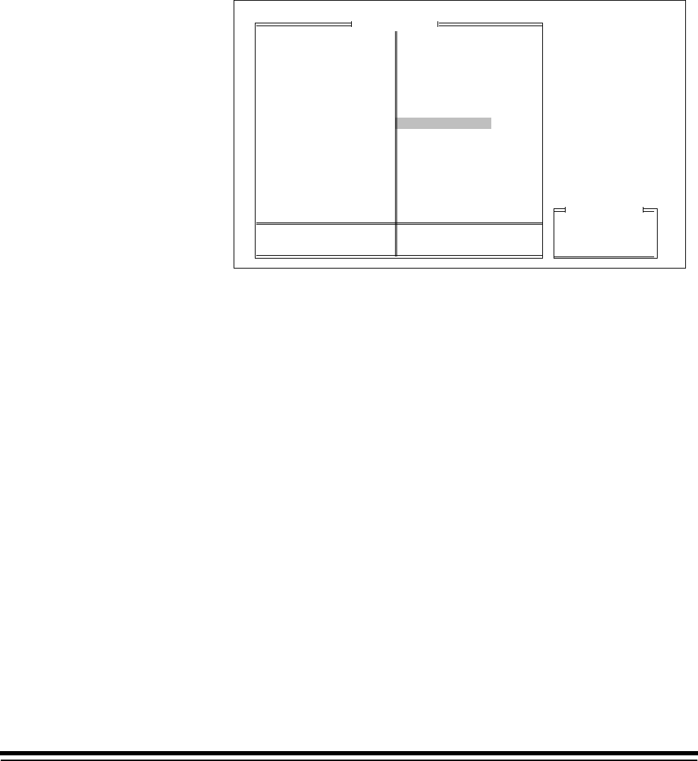
3-78 A-61097 May 1997
OCR Status
NOTE: The OCR accessory must be installed.
Enables or disables Optical Character Recognition. The default value is
Off or Disabled.
❏Microimager 70 ■Microimager 70/AFM ■Scanner 900
■Scanner 923 ■Scanner/Microimager 990 ❏Scanner 9500
1. Select OCR Status.
Mode Configuration
Don't Save & End Session
End Configuration
Save & End Session
Previous Menu
Mode Number: 10 Mode Name: MODE10
FieldOCR Status
MODE 10
3 Lvl
Supprs
4233
2112
None
Auto
Duplex
?????
1 Roll
Comic
Off
Off
Off
Xport
Off
Undef
Undef
Off
Off
Off
Lvl 2
Off
N N N
Off
On
Disply
Off
Off
Off
Off
No Sav
F
Mode Name
Index Format
IA Display Format
IA Field Widths
Level Rules
Batching
AEC Mode
Film Mode
Reduction Ratio
# of Cassettes
Film Writer
Image Mgmt Code
Length Monitor
Skew Monitor
Check Stacker
Endorser
Not Used
Ftswitch Pressed
Ftswitch Released
Ftswitch Cnf Tone
Patch Reader 1
Patch Reader 2
Patch Definition
Bar Code
Confirmation Tone
OCR Status
COIN User Channel
Printer Control
Primary DP-1
Secondary DP-1
Doc. Printer 12
Document Sorter
Mode Overrides
Film Definition
Off or Disabled
On or Enabled
Previous Menu
2. Select the desired status.
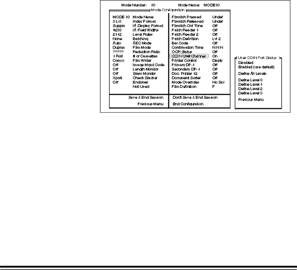
A-61097 May 1997 3-79
COIN User Channel
NOTE: If the machine definition User COIN Port Protocol was disabled,
these definitions will be ignored.
Enables or disables the COIN2 user channel.
If a standard form of output was chosen during machine definition (Bar
Code/KDIS Protocol or OCR Data Protocol), this definition should be set
to Enabled which will produce default/standard data output via the COIN2
port.
If a user-defined form of output was chosen during machine definition
(User-Defined KDIS Format or User-Defined Protocol), select Define All
Levels or select a particular level. The default value is Disabled.
❏Microimager 70 ■Microimager 70/AFM ■Scanner 900
■Scanner 923 ■Scanner/Microimager 990 ■Scanner 9500
1. Select COIN User Channel.
2. Select the desired status.

3-80 A-61097 May 1997
Transmit Data
This mode defines the data output via the COIN2 port when a user-
defined protocol (User-Defined KDIS Format or User-Defined Protocol) is
chosen during machine definition. The default values are FF/IA for all
levels.
❏Microimager 70 ■Microimager 70/AFM ■Scanner 900
■Scanner 923 ■Scanner/Microimager 990 ■Scanner 9500
If the same information is to be transmitted for documents of all levels:
1. Select Define All Levels.
Transmit Items
Current Transmit Sequence
New Transmit Sequence
<FF/IA>
Full Image Address
Indexed Field(s) Only
Current Field Value
Current Day
Current Date
Current Time
Document Counter
Roll Number
Attachment Count
Bar Code Data
Nothing
Previous Menu
When using a Microimager 70 with the Advanced Function Module
installed, Scanner 900, Scanner 923, Scanner 9500, or Scanner/
Microimager 990, all of the transmit items are available for selection, with
a maximum of seven (7) items.
2. Select the item(s) to be transmitted.

A-61097 May 1997 3-81
If different information is to be transmitted for documents of different
levels:
1. Select Define Level # for the desired level.
Transmit Items
Current Transmit Sequence
New Transmit Sequence
<FF/IA>
Full Image Address
Indexed Field(s) Only
Current Field Value
Current Day
Current Date
Current Time
Document Counter
Roll Number
Attachment Count
Bar Code Data
Nothing
Previous Menu
When using a Microimager 70 without the Advanced Function Module
installed, a limited number of transmit items may be selected. The valid
items are:
• Full Image Address
• Nothing
When using a Microimager 70 with the Advanced Function Module
installed, Scanner 900, Scanner 923, Scanner 9500, or Scanner/
Microimager 990, all of the transmit items are available for selection, with
a maximum of seven (7) items.
2. Select the item(s) to be transmitted.
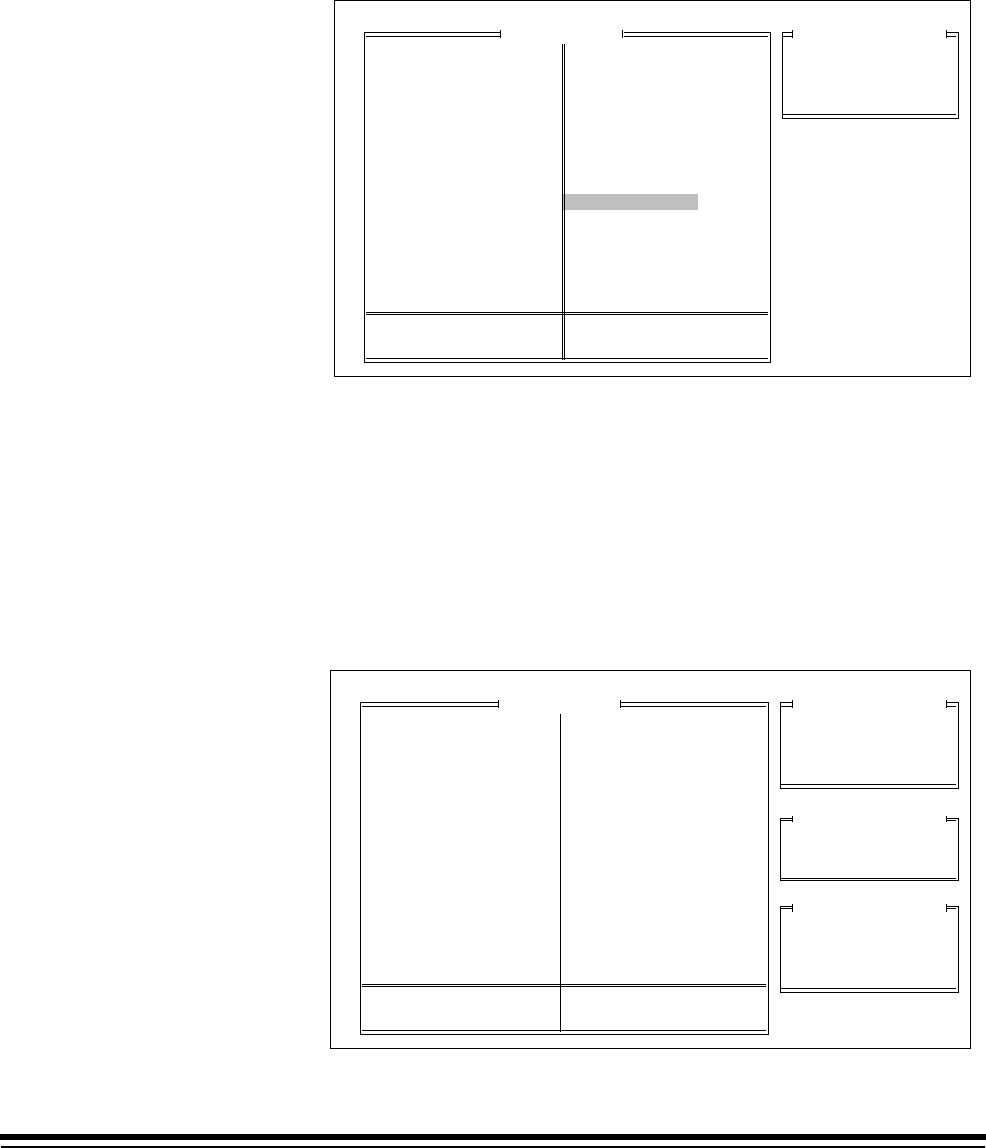
3-82 A-61097 May 1997
Printer Control
NOTE: The Document Printer Controller must be installed
■Microimager 70 ■Microimager 70/AFM ■Scanner 900
■Scanner 923 ■Scanner/Microimager 990 ■Scanner 9500
1. Select Printer Control.
Printer Control
Mode Configuration
Don't Save & End Session
End Configuration
Save & End Session
Previous Menu
Mode Number: 10 Mode Name: MODE10
MODE 10
3 Lvl
Supprs
4233
2112
None
Auto
Duplex
?????
1 Roll
Comic
Off
Off
Off
Xport
Off
Undef
Undef
Off
Off
Off
Lvl 2
Off
N N N
Off
On
Disply
Off
Off
Off
Off
No Sav
F
Mode Name
Index Format
IA Display Format
IA Field Widths
Level Rules
Batching
AEC Mode
Film Mode
Reduction Ratio
# of Cassettes
Film Writer
Image Mgmt Code
Length Monitor
Skew Monitor
Check Stacker
Endorser
Not Used
Ftswitch Pressed
Ftswitch Released
Ftswitch Cnf Tone
Patch Reader 1
Patch Reader 2
Patch Definition
Bar Code
Confirmation Tone
OCR Status
COIN User Channel
Printer Control
Primary DP-1
Secondary DP-1
Doc. Printer 12
Document Sorter
Mode Overrides
Film Definition
IA Print Format
Print Position
Special Character Set
Previous Menu
Image Address Print Format
This mode defines the format used by the document printer(s) when
printing the Image Address. The default value is Display.
❏Microimager 70 ■Microimager 70/AFM ■Scanner 900
■Scanner 923 ■Scanner/Microimager 990 ■Scanner 9500
1. Select IA Print Format.
Printer Control
Mode Configuration
Don't Save & End Session
End Configuration
Save & End Session
Previous Menu
Mode Number: 10 Mode Name: MODE10
DP IA Display Format
Examples of Formats
MODE 10
3 Lvl
Supprs
4233
2112
None
Auto
Duplex
?????
1 Roll
Comic
Off
Off
Off
Xport
Off
Undef
Undef
Off
Off
Off
Lvl 2
Off
N N N
Off
On
Disply
Off
Off
Off
Off
No Sav
F
Mode Name
Index Format
IA Display Format
IA Field Widths
Level Rules
Batching
AEC Mode
Film Mode
Reduction Ratio
# of Cassettes
Film Writer
Image Mgmt Code
Length Monitor
Skew Monitor
Check Stacker
Endorser
Not Used
Ftswitch Pressed
Ftswitch Released
Ftswitch Cnf Tone
Patch Reader 1
Patch Reader 2
Patch Definition
Bar Code
Confirmation Tone
OCR Status
COIN User Channel
Printer Control
Primary DP-1
Secondary DP-1
Doc. Printer 12
Document Sorter
Mode Overrides
Film Definition
IA Print Format
Print Position
Special Character Set
Previous Menu
Display:
Compress:
Suppress:
001.002.003.004
001.2.3.4
001. 002.003.004
Display Leading Zeroes
Compress Leading Zeroes
Suppress Leading Zeroes
Previous Menu
2. Select the desired print format.

A-61097 May 1997 3-83
Print Position
This mode defines how far from the leading edge of the document(s) the
information printed by the document printer(s) will appear. The default
value is 00.250 inch/6.25 mm.
■Microimager 70 ■Microimager 70/AFM ■Scanner 900
■Scanner 923 ■Scanner/Microimager 990 ■Scanner 9500
1. Select Print Position.
Printer Control
Mode Configuration
Don't Save & End Session
End Configuration
Save & End Session
Previous Menu
Mode Number: 10 Mode Name: MODE10
Enter Print Position
Range: 0.125...20.000
0000.250
MODE 10
3 Lvl
Supprs
4233
2112
None
Auto
Duplex
?????
1 Roll
Comic
Off
Off
Off
Xport
Off
Undef
Undef
Off
Off
Off
Lvl 2
Off
N N N
Off
On
Disply
Off
Off
Off
Off
No Sav
F
Mode Name
Index Format
IA Display Format
IA Field Widths
Level Rules
Batching
AEC Mode
Film Mode
Reduction Ratio
# of Cassettes
Film Writer
Image Mgmt Code
Length Monitor
Skew Monitor
Check Stacker
Endorser
Not Used
Ftswitch Pressed
Ftswitch Released
Ftswitch Cnf Tone
Patch Reader 1
Patch Reader 2
Patch Definition
Bar Code
Confirmation Tone
OCR Status
COIN User Channel
Printer Control
Primary DP-1
Secondary DP-1
Doc. Printer 12
Document Sorter
Mode Overrides
Film Definition
IA Print Format
Print Position
Special Character Set
Previous Menu
2. Select the desired print position with the range 0.125 to 75 inches or
3.000 to 1905.000 mm).
3-84 A-61097 May 1997
Special Character Set
This mode defines the size font to be printed. Select either the smaller or
larger font size when using the Document Printer 12. The default value is
Use Smaller Font.
NOTE: This selection is not available if the wrong printer driver board is
installed. The following message appears:
Incorrect revision of 3100 PCB for Bigfoot Font
❏Microimager 70 ■Microimager 70/AFM ■Scanner 900
■Scanner 923 ■Scanner/Microimager 990 ■Scanner 9500
1. Select Special Character Set.
Printer Control
Mode Configuration
Don't Save & End Session
End Configuration
Save & End Session
Previous Menu
Mode Number: 10 Mode Name: MODE10
Field
Character Set
MODE 10
3 Lvl
Supprs
4233
2112
None
Auto
Duplex
?????
1 Roll
Comic
Off
Off
Off
Xport
Off
Undef
Undef
Off
Off
Off
Lvl 2
Off
N N N
Off
On
Disply
Off
Off
Off
Off
No Sav
F
Mode Name
Index Format
IA Display Format
IA Field Widths
Level Rules
Batching
AEC Mode
Film Mode
Reduction Ratio
# of Cassettes
Film Writer
Image Mgmt Code
Length Monitor
Skew Monitor
Check Stacker
Endorser
Not Used
Ftswitch Pressed
Ftswitch Released
Ftswitch Cnf Tone
Patch Reader 1
Patch Reader 2
Patch Definition
Bar Code
Confirmation Tone
OCR Status
COIN User Channel
Printer Control
Primary DP-1
Secondary DP-1
Doc. Printer 12
Document Sorter
Mode Overrides
Film Definition
IA Print Format
Print Position
Special Character Set
Previous Menu
Use Smaller Font
Use Larger Font
Previous Menu
2. Select the desired font size.
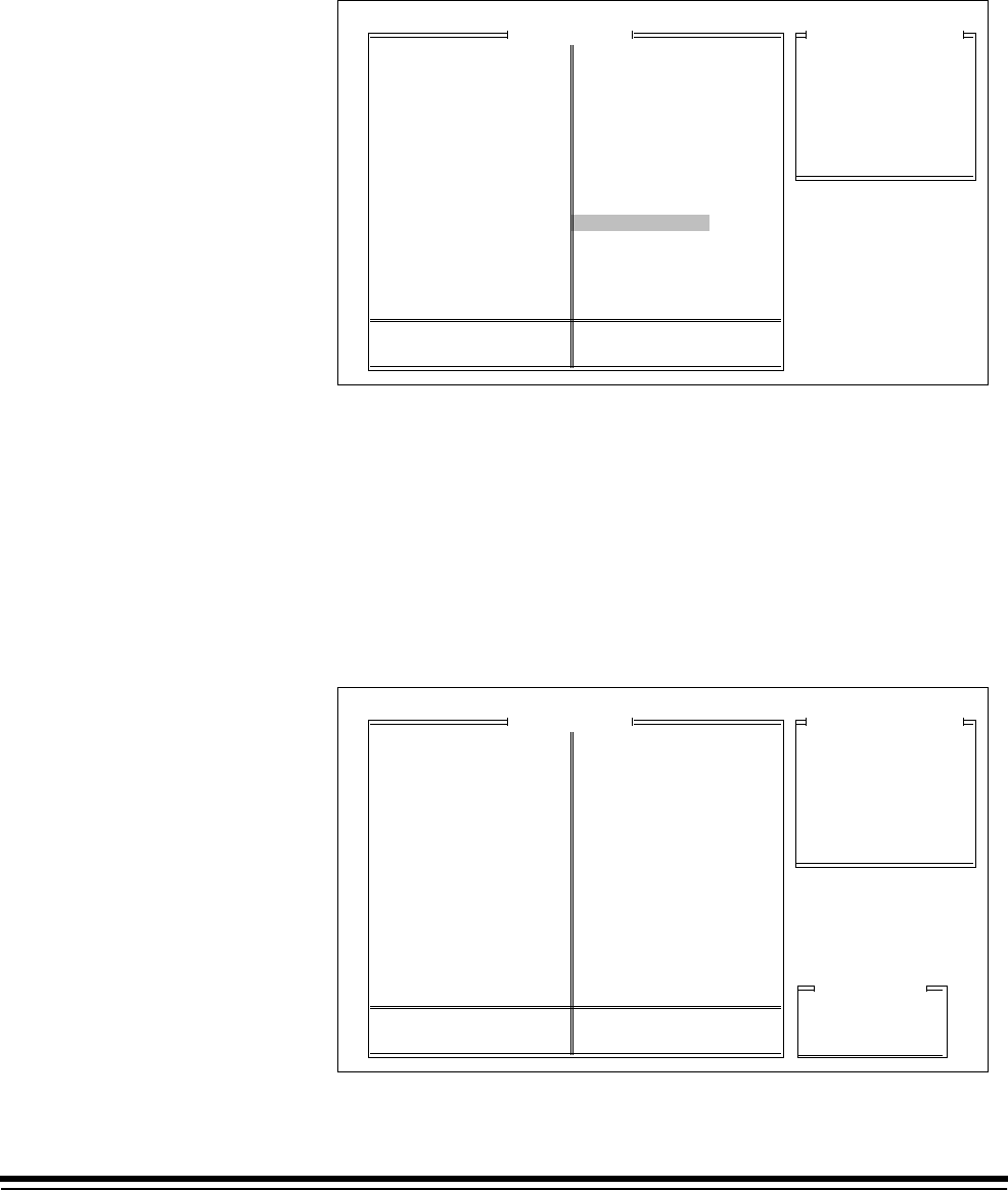
A-61097 May 1997 3-85
Primary Document Printer 1
NOTE: A Document Printer 1 accessory must be installed.
■Microimager 70 ■Microimager 70/AFM ■Scanner 900
■Scanner 923 ■Scanner/Microimager 990 ■Scanner 9500
1. Select Primary DP-1.
Primary Document Printer
Mode Configuration
Don't Save & End Session
End Configuration
Save & End Session
Previous Menu
Mode Number: 10 Mode Name: MODE10
MODE 10
3 Lvl
Supprs
4233
2112
None
Auto
Duplex
?????
1 Roll
Comic
Off
Off
Off
Xport
Off
Undef
Undef
Off
Off
Off
Lvl 2
Off
N N N
Off
On
Disply
Off
Off
Off
Off
No Sav
F
Mode Name
Index Format
IA Display Format
IA Field Widths
Level Rules
Batching
AEC Mode
Film Mode
Reduction Ratio
# of Cassettes
Film Writer
Image Mgmt Code
Length Monitor
Skew Monitor
Check Stacker
Endorser
Not Used
Ftswitch Pressed
Ftswitch Released
Ftswitch Cnf Tone
Patch Reader 1
Patch Reader 2
Patch Definition
Bar Code
Confirmation Tone
OCR Status
COIN User Channel
Printer Control
Primary DP-1
Secondary DP-1
Doc. Printer 12
Document Sorter
Mode Overrides
Film Definition
Document Printer Status
Fonts/Orientation
Same Format per Level
Print Sequence - Level 0
Print Sequence - Level 1
Print Sequence - Level 2
Print Sequence - Level 3
Previous Menu
Document Printer Status
This mode enables or disables the primary Document Printer 1. The
default value is Off or Disabled.
■Microimager 70 ■Microimager 70/AFM ■Scanner 900
■Scanner 923 ■Scanner/Microimager 990 ■Scanner 9500
1. Select Document Printer Status.
Document Printer Status
Fonts/Orientation
Same Format per Level
Print Sequence - Level 0
Print Sequence - Level 1
Print Sequence - Level 2
Print Sequence - Level 3
Previous Menu
Primary Document Printer
Mode Configuration
Don't Save & End Session
End Configuration
Save & End Session
Previous Menu
Mode Number: 10 Mode Name: MODE10
FieldPrimary Status
MODE 10
3 Lvl
Supprs
4233
2112
None
Auto
Duplex
?????
1 Roll
Comic
Off
Off
Off
Xport
Off
Undef
Undef
Off
Off
Off
Lvl 2
Off
N N N
Off
On
Disply
Off
Off
Off
Off
No Sav
F
Mode Name
Index Format
IA Display Format
IA Field Widths
Level Rules
Batching
AEC Mode
Film Mode
Reduction Ratio
# of Cassettes
Film Writer
Image Mgmt Code
Length Monitor
Skew Monitor
Check Stacker
Endorser
Not Used
Ftswitch Pressed
Ftswitch Released
Ftswitch Cnf Tone
Patch Reader 1
Patch Reader 2
Patch Definition
Bar Code
Confirmation Tone
OCR Status
COIN User Channel
Printer Control
Primary DP-1
Secondary DP-1
Doc. Printer 12
Document Sorter
Mode Overrides
Film Definition
Off or Disabled
On or Enabled
Previous Menu
2. Select the desired status.

3-86 A-61097 May 1997
Fonts/Orientation
This mode defines the size and orientation of the characters printed by the
primary Document Printer 1. The default value is Off or Disabled.
■Microimager 70 ■Microimager 70/AFM ■Scanner 900
■Scanner 923 ■Scanner/Microimager 990 ■Scanner 9500
1. Select Fonts/Orientation.
Document Printer Status
Fonts/Orientation
Same Format per Level
Print Sequence - Level 0
Print Sequence - Level 1
Print Sequence - Level 2
Print Sequence - Level 3
Previous Menu
Primary Document Printer
Mode Configuration
Don't Save & End Session
End Configuration
Save & End Session
Previous Menu
Mode Number: 10 Mode Name: MODE10
Small Font - Comic
Small Font - Cine
Small Font - Comic 180
Small Font - Cine 180
Large Font - Comic
Large Font - Cine
Large Font - Comic 180
Large Font - Cine 180
Previous Menu
FieldDP-1 Font Selection
MODE 10
3 Lvl
Supprs
4233
2112
None
Auto
Duplex
?????
1 Roll
Comic
Off
Off
Off
Xport
Off
Undef
Undef
Off
Off
Off
Lvl 2
Off
N N N
Off
On
Disply
Off
Off
Off
Off
No Sav
F
Mode Name
Index Format
IA Display Format
IA Field Widths
Level Rules
Batching
AEC Mode
Film Mode
Reduction Ratio
# of Cassettes
Film Writer
Image Mgmt Code
Length Monitor
Skew Monitor
Check Stacker
Endorser
Not Used
Ftswitch Pressed
Ftswitch Released
Ftswitch Cnf Tone
Patch Reader 1
Patch Reader 2
Patch Definition
Bar Code
Confirmation Tone
OCR Status
COIN User Channel
Printer Control
Primary DP-1
Secondary DP-1
Doc. Printer 12
Document Sorter
Mode Overrides
Film Definition
2. Select the desired size and font (four orientations).
COMIC
C
I
N
E
COMIC180
C
I
N
E
1
8
0

A-61097 May 1997 3-87
Print Definitions
This mode defines the information printed on each document, based upon
the document level.
The default values are Nothing Printed for Level 0 documents; Full Image
Address with all delimiters for Level 1, Level 2, and Level 3 documents
<FF/IA All Del>.
■Microimager 70 ■Microimager 70/AFM ■Scanner 900
■Scanner 923 ■Scanner/Microimager 990 ■Scanner 9500
If the same information is to be printed on documents of all levels:
1. Select Same Format per Level.
Print Items
Current Print Sequence Display Values
New Print Sequence Display Values
Full IA w/No Delimiters
Full IA w/FF Delimiter
Full IA w/All Delimiter
Fixed Field Only
Indexed Fields Only
Current Field Level
Spaces between Items
Current Day
Current Date
Current Time
Document Counter
Roll Number
Message 1-9
Check Digit
Nothing Printed
Previous Menu
When using a Microimager 70 without the Advanced Function Module
installed, a limited number of items may be selected. The available items
are:
• Full IA w/ All Delimiter
• Indexed Fields Only
• Nothing Printed
When using a Microimager 70 with the Advanced Function Module
installed, all of the items are available for selection, with a maximum of
38 characters (including spaces).
NOTE: If the definition exceeds the 38 character limit, the first 38
characters will be printed on each document and the remainder of
the information will be truncated.
2. Select the item(s) to be printed.

3-88 A-61097 May 1997
If Spaces between items is selected, you must select the desired number
of spaces.
If Check Digit is selected, the following window is displayed:
Check Digit
Current Print Sequence Display Values
New Print Sequence Display Values
Mod 7A IA Only
Mod 11A IA Only
Mod 7B IA Only
Mod 7B Full IA
Mod 10 IA Only
Mod 10 Full IA
Mod 11B IA Only
Mod 11B Full IA
Custom IA Only
Custom Full IA
Previous Menu
2. Select the desired check digit calculation.
If an option which indicates IA Only is chosen, the level fields of the Image
Address will be printed; the Fixed Field will not be printed. If an option
which indicates Full IA is chosen, the Fixed Field and level fields of the
Image Address will be printed.
NOTE: If Customer - IA Only or Customer - Full IA is chosen, the Check
Digit options must be defined.
If Message Number is selected, the following window is displayed:
Message Number 1
Message Number 2
Message Number 3
Message Number 4
Message Number 5
Message Number 6
Message Number 7
Message Number 8
Message Number 9
Previous Menu
Message Number
Current Print Sequence Display Values
New Print Sequence Display Values
1. Select the desired message number.

A-61097 May 1997 3-89
If different information is to be printed on documents of different levels:
1. Select Print Sequence - Level # for the desired level.
Print Items
Current Print Sequence Display Values
New Print Sequence Display Values
Full IA w/No Delimiters
Full IA w/FF Delimiter
Full IA w/All Delimiter
Fixed Field Only
Indexed Fields Only
Current Field Level
Spaces between Items
Current Day
Current Date
Current Time
Document Counter
Roll Number
Message 1-9
Check Digit
Nothing Printed
Previous Menu
When using a Microimager 70 without the Advanced Function Module
installed, a limited number of items may be selected. The available items
are:
• Full IA w/ All Delimiter
• Indexed Fields Only
• Nothing Printed
When using a Microimager 70 with the Advanced Function Module
installed, all of the items are available for selection, with a maximum of
38 characters (including spaces).
If Check Digit is selected, the following window is displayed:
NOTE: If the definition exceeds the thirty-eight (38) character limits, the
first thirty-eight (38) characters will be printed on each document
and the remainder of the information will be truncated.
2. Select the item(s) to be printed.

3-90 A-61097 May 1997
Secondary Document Printer 1
NOTE: Two Document Printer 1 accessories must be installed.
❏Microimager 70 ■Microimager 70/AFM ■Scanner 900
■Scanner 923 ■Scanner/Microimager 990 ■Scanner 9500
1. Select Secondary DP-1.
Second Document Printer
Mode Configuration
Don't Save & End Session
End Configuration
Save & End Session
Previous Menu
Mode Number: 10 Mode Name: MODE10
MODE 10
3 Lvl
Supprs
4233
2112
None
Auto
Duplex
?????
1 Roll
Comic
Off
Off
Off
Xport
Off
Undef
Undef
Off
Off
Off
Lvl 2
Off
N N N
Off
On
Disply
Off
Off
Off
Off
No Sav
F
Mode Name
Index Format
IA Display Format
IA Field Widths
Level Rules
Batching
AEC Mode
Film Mode
Reduction Ratio
# of Cassettes
Film Writer
Image Mgmt Code
Length Monitor
Skew Monitor
Check Stacker
Endorser
Not Used
Ftswitch Pressed
Ftswitch Released
Ftswitch Cnf Tone
Patch Reader 1
Patch Reader 2
Patch Definition
Bar Code
Confirmation Tone
OCR Status
COIN User Channel
Printer Control
Primary DP-1
Secondary DP-1
Doc. Printer 12
Document Sorter
Mode Overrides
Film Definition
Document Printer Status
Fonts/Orientation
Same Format per Level
Print Sequence - Level 0
Print Sequence - Level 1
Print Sequence - Level 2
Print Sequence - Level 3
Previous Menu
A-61097 May 1997 3-91
Document Printer Status
Enables or disables the secondary Document Printer 1. The default value
is Off or Disabled.
❏Microimager 70 ■Microimager 70/AFM ■Scanner 900
■Scanner 923 ■Scanner/Microimager 990 ■Scanner 9500
1. Select Document Printer Status.
Second Document Printer
Mode Configuration
Don't Save & End Session
End Configuration
Save & End Session
Previous Menu
Mode Number: 10 Mode Name: MODE10
Field
Secondary DP-1
MODE 10
3 Lvl
Supprs
4233
2112
None
Auto
Duplex
?????
1 Roll
Comic
Off
Off
Off
Xport
Off
Undef
Undef
Off
Off
Off
Lvl 2
Off
N N N
Off
On
Disply
Off
Off
Off
Off
No Sav
F
Mode Name
Index Format
IA Display Format
IA Field Widths
Level Rules
Batching
AEC Mode
Film Mode
Reduction Ratio
# of Cassettes
Film Writer
Image Mgmt Code
Length Monitor
Skew Monitor
Check Stacker
Endorser
Not Used
Ftswitch Pressed
Ftswitch Released
Ftswitch Cnf Tone
Patch Reader 1
Patch Reader 2
Patch Definition
Bar Code
Confirmation Tone
OCR Status
COIN User Channel
Printer Control
Primary DP-1
Secondary DP-1
Doc. Printer 12
Document Sorter
Mode Overrides
Film Definition
Document Printer Status
Fonts/Orientation
Same Format per Level
Print Sequence - Level 0
Print Sequence - Level 1
Print Sequence - Level 2
Print Sequence - Level 3
Previous Menu
Off or Disabled
On or Enabled
Previous Menu
2. Select the desired status.

3-92 A-61097 May 1997
Fonts/Orientation—DP2
This mode defines the size and orientation of the characters printed by the
secondary Document Printer 1. The default value is Off or Disabled.
❏Microimager 70 ■Microimager 70/AFM ■Scanner 900
■Scanner 923 ■Scanner/Microimager 990 ■Scanner 9500
1. Select Fonts/Orientation.
Second Document Printer
Mode Configuration
Don't Save & End Session
End Configuration
Save & End Session
Previous Menu
Mode Number: 10 Mode Name: MODE10
Small Font - Comic
Small Font - Cine
Small Font - Comic 180
Small Font - Cine 180
Large Font - Comic
Large Font - Cine
Large Font - Comic 180
Large Font - Cine 180
Previous Menu
FieldDP-1 Font Selection
MODE 10
3 Lvl
Supprs
4233
2112
None
Auto
Duplex
?????
1 Roll
Comic
Off
Off
Off
Xport
Off
Undef
Undef
Off
Off
Off
Lvl 2
Off
N N N
Off
On
Disply
Off
Off
Off
Off
No Sav
F
Mode Name
Index Format
IA Display Format
IA Field Widths
Level Rules
Batching
AEC Mode
Film Mode
Reduction Ratio
# of Cassettes
Film Writer
Image Mgmt Code
Length Monitor
Skew Monitor
Check Stacker
Endorser
Not Used
Ftswitch Pressed
Ftswitch Released
Ftswitch Cnf Tone
Patch Reader 1
Patch Reader 2
Patch Definition
Bar Code
Confirmation Tone
OCR Status
COIN User Channel
Printer Control
Primary DP-1
Secondary DP-1
Doc. Printer 12
Document Sorter
Mode Overrides
Film Definition
Document Printer Status
Fonts/Orientation
Same Format per Level
Print Sequence - Level 0
Print Sequence - Level 1
Print Sequence - Level 2
Print Sequence - Level 3
Previous Menu
2. Select the desired size and font (four orientations).
COMIC
C
I
N
E
COMIC180
C
I
N
E
1
8
0

A-61097 May 1997 3-93
Print Definitions—DP2
This mode defines the information printed on each document, based upon
the document level. The default values are Nothing Printed for Level 0
documents; Full Image Address with all delimiters for Level 1, Level 2, and
Level 3 documents.
❏Microimager 70 ■Microimager 70/AFM ■Scanner 900
■Scanner 923 ■Scanner/Microimager 990 ■Scanner 9500
If the same information is to be printed on documents of all levels:
1. Select Same Format per Level.
Full IA w/No Delimiters
Full IA w/FF Delimiter
Full IA w/All Delimiter
Fixed Field Only
Indexed Fields Only
Current Field Level
Spaces between Items
Current Day
Current Date
Current Time
Document Counter
Roll Number
Message 1-9
Check Digit
Nothing Printed
Previous Menu
Print Items
Current Print Sequence Display Values
New Print Sequence Display Values
2. Select the item(s) to be printed, in turn, up to a maximum of thirty-
eight (38) characters, including spaces.
NOTE: If the definition exceeds the thirty-eight (38) character limit, the
first thirty-eight (38) characters will be printed on each document
and the remainder of the information will be truncated.
If Spaces between Items is selected, you must select the desired number
of spaces.

3-94 A-61097 May 1997
If Check Digit is selected, the following window is displayed:
Check Digit
Current Print Sequence Display Values
New Print Sequence Display Values
Mod 7A IA Only
Mod 11A IA Only
Mod 7B IA Only
Mod 7B Full IA
Mod 10 IA Only
Mod 10 Full IA
Mod 11B IA Only
Mod 11B Full IA
Custom IA Only
Custom Full IA
Previous Menu
3. Select the desired check digit calculation.
If an option which indicates IA Only is chosen, the level fields of the Image
Address will be printed; the Fixed Field will not be printed. If an option
which indicates Full IA is chosen, the Fixed Field and level fields of the
Image Address will be printed.
NOTE: If Customer—IA Only or Customer—Full IA is chosen, the Check
Digit options must be defined.

A-61097 May 1997 3-95
If Message Number is selected, the following window is displayed:
Message Number 1
Message Number 2
Message Number 3
Message Number 4
Message Number 5
Message Number 6
Message Number 7
Message Number 8
Message Number 9
Previous Menu
Message Number
Current Print Sequence Display Values
New Print Sequence Display Values
4. Select the desired message number.
If different information is to be printed on documents of different levels:
5. Select Print Sequence—Level # for the desired level.
6. Select the item(s) to be printed next to documents of the selected
level, in turn, up to a maximum of thirty-eight (38) characters, including
spaces.
NOTE: If the definition exceeds the thirty-eight (38) character limit, the
first thirty-eight (38) characters will be printed on each document
and the remainder of the information will be truncated.

3-96 A-61097 May 1997
Document Printer 12
NOTE: The Document Printer 12 accessory must be installed
■Microimager 70 ■Microimager 70/AFM ■Scanner 900
■Scanner 923 ■Scanner/Microimager 990 ■Scanner 9500
1. Select Doc. Printer 12.
Document Printer 12
Mode Configuration
Don't Save & End Session
End Configuration
Save & End Session
Previous Menu
Mode Number: 10 Mode Name: MODE10
MODE 10
3 Lvl
Supprs
4233
2112
None
Auto
Duplex
?????
1 Roll
Comic
Off
Off
Off
Xport
Off
Undef
Undef
Off
Off
Off
Lvl 2
Off
N N N
Off
On
Disply
Off
Off
Off
Off
No Sav
F
Mode Name
Index Format
IA Display Format
IA Field Widths
Level Rules
Batching
AEC Mode
Film Mode
Reduction Ratio
# of Cassettes
Film Writer
Image Mgmt Code
Length Monitor
Skew Monitor
Check Stacker
Endorser
Not Used
Ftswitch Pressed
Ftswitch Released
Ftswitch Cnf Tone
Patch Reader 1
Patch Reader 2
Patch Definition
Bar Code
Confirmation Tone
OCR Status
COIN User Channel
Printer Control
Primary DP-1
Secondary DP-1
Doc. Printer 12
Document Sorter
Mode Overrides
Film Definition
Document Printer Status
Fonts/Orientation
Same Format per Level
Print Sequence - Level 0
Print Sequence - Level 1
Print Sequence - Level 2
Print Sequence - Level 3
Previous Menu

A-61097 May 1997 3-97
Document Printer Status—DP12
Enables or disables the Document Printer 12. The default value is Off or
Disabled.
■Microimager 70 ■Microimager 70/AFM ■Scanner 900
■Scanner 923 ■Scanner/Microimager 990 ■Scanner 9500
1. Select Document Printer Status.
FieldPAW 12 Status
Document Printer 12
Mode Configuration
Don't Save & End Session
End Configuration
Save & End Session
Previous Menu
Mode Number: 10 Mode Name: MODE10
MODE 10
3 Lvl
Supprs
4233
2112
None
Auto
Duplex
?????
1 Roll
Comic
Off
Off
Off
Xport
Off
Undef
Undef
Off
Off
Off
Lvl 2
Off
N N N
Off
On
Disply
Off
Off
Off
Off
No Sav
F
Mode Name
Index Format
IA Display Format
IA Field Widths
Level Rules
Batching
AEC Mode
Film Mode
Reduction Ratio
# of Cassettes
Film Writer
Image Mgmt Code
Length Monitor
Skew Monitor
Check Stacker
Endorser
Not Used
Ftswitch Pressed
Ftswitch Released
Ftswitch Cnf Tone
Patch Reader 1
Patch Reader 2
Patch Definition
Bar Code
Confirmation Tone
OCR Status
COIN User Channel
Printer Control
Primary DP-1
Secondary DP-1
Doc. Printer 12
Document Sorter
Mode Overrides
Film Definition
Off or Disabled
On or Enabled
Previous Menu
Document Printer Status
Fonts/Orientation
Same Format per Level
Print Sequence - Level 0
Print Sequence - Level 1
Print Sequence - Level 2
Print Sequence - Level 3
Previous Menu
2. Select the desired status.
3-98 A-61097 May 1997
Fonts/Orientation—DP12
This mode defines the size and orientation of the characters printed by the
Document Printer 12. The default value is Comic Orientation.
■Microimager 70 ■Microimager 70/AFM ■Scanner 900
■Scanner 923 ■Scanner/Microimager 990 ■Scanner 9500
1. Select Fonts/Orientation.
Field
DP-12 Font Selection
Document Printer 12
Mode Configuration
Don't Save & End Session
End Configuration
Save & End Session
Previous Menu
Mode Number: 10 Mode Name: MODE10
MODE 10
3 Lvl
Supprs
4233
2112
None
Auto
Duplex
?????
1 Roll
Comic
Off
Off
Off
Xport
Off
Undef
Undef
Off
Off
Off
Lvl 2
Off
N N N
Off
On
Disply
Off
Off
Off
Off
No Sav
F
Mode Name
Index Format
IA Display Format
IA Field Widths
Level Rules
Batching
AEC Mode
Film Mode
Reduction Ratio
# of Cassettes
Film Writer
Image Mgmt Code
Length Monitor
Skew Monitor
Check Stacker
Endorser
Not Used
Ftswitch Pressed
Ftswitch Released
Ftswitch Cnf Tone
Patch Reader 1
Patch Reader 2
Patch Definition
Bar Code
Confirmation Tone
OCR Status
COIN User Channel
Printer Control
Primary DP-1
Secondary DP-1
Doc. Printer 12
Document Sorter
Mode Overrides
Film Definition
Comic Orientation
Comic 180 Orientation
Previous Menu
Document Printer Status
Fonts/Orientation
Same Format per Level
Print Sequence - Level 0
Print Sequence - Level 1
Print Sequence - Level 2
Print Sequence - Level 3
Previous Menu
2. Select the desired size and font.
COMIC
A-61097 May 1997 3-99
Print Definitions—DP12
This mode defines the information printed on each document, based upon
the document level. The default values are No Print Template for Level 0
documents; Print Template for Level 1, Level 2, and Level 3 documents.
The default is IA-No Del.
■Microimager 70 ■Microimager 70/AFM ■Scanner 900
■Scanner 923 ■Scanner/Microimager 990 ■Scanner 9500
If the same information is to be printed on documents of all levels.
1. Select Same Format per Level.
Print Template 1
Print Template 2
Print Template 3
Print Template 4
Print Template 5
Print Template 6
Print Template 7
Print Template 8
Print Template 9
Print Template 10
No Print Template
Previous Menu
FieldPrint Level*
Document Printer 12
Mode Configuration
Don't Save & End Session
End Configuration
Save & End Session
Previous Menu
Mode Number: 10 Mode Name: MODE10
MODE 10
3 Lvl
Supprs
4233
2112
None
Auto
Duplex
?????
1 Roll
Comic
Off
Off
Off
Xport
Off
Undef
Undef
Off
Off
Off
Lvl 2
Off
N N N
Off
On
Disply
Off
Off
Off
Off
No Sav
F
Mode Name
Index Format
IA Display Format
IA Field Widths
Level Rules
Batching
AEC Mode
Film Mode
Reduction Ratio
# of Cassettes
Film Writer
Image Mgmt Code
Length Monitor
Skew Monitor
Check Stacker
Endorser
Not Used
Ftswitch Pressed
Ftswitch Released
Ftswitch Cnf Tone
Patch Reader 1
Patch Reader 2
Patch Definition
Bar Code
Confirmation Tone
OCR Status
COIN User Channel
Printer Control
Primary DP-1
Secondary DP-1
Doc. Printer 12
Document Sorter
Mode Overrides
Film Definition
Document Printer Status
Fonts/Orientation
Same Format per Level
Print Sequence - Level 0
Print Sequence - Level 1
Print Sequence - Level 2
Print Sequence - Level 3
Previous Menu
When using a Microimager 70 without the Advanced Function Module
installed, a limited number of items may be selected. The available items
are:
• Print Template 1
• No Print Template

3-100 A-61097 May 1997
When using a Microimager 70 with the Advanced Function Module
installed, all of the print templates defined during machine configuration
are available for selection.
2. Select the print template which contains the information to be printed
on all documents.
3. Select Print Sequence—Level # for the desired level.
Print Template 1
Print Template 2
Print Template 3
Print Template 4
Print Template 5
Print Template 6
Print Template 7
Print Template 8
Print Template 9
Print Template 10
No Print Template
Previous Menu
FieldPrint Level*
Document Printer 12
Mode Configuration
Don't Save & End Session
End Configuration
Save & End Session
Previous Menu
Mode Number: 10 Mode Name: MODE10
MODE 10
3 Lvl
Supprs
4233
2112
None
Auto
Duplex
?????
1 Roll
Comic
Off
Off
Off
Xport
Off
Undef
Undef
Off
Off
Off
Lvl 2
Off
N N N
Off
On
Disply
Off
Off
Off
Off
No Sav
F
Mode Name
Index Format
IA Display Format
IA Field Widths
Level Rules
Batching
AEC Mode
Film Mode
Reduction Ratio
# of Cassettes
Film Writer
Image Mgmt Code
Length Monitor
Skew Monitor
Check Stacker
Endorser
Not Used
Ftswitch Pressed
Ftswitch Released
Ftswitch Cnf Tone
Patch Reader 1
Patch Reader 2
Patch Definition
Bar Code
Confirmation Tone
OCR Status
COIN User Channel
Printer Control
Primary DP-1
Secondary DP-1
Doc. Printer 12
Document Sorter
Mode Overrides
Film Definition
Document Printer Status
Fonts/Orientation
Same Format per Level
Print Sequence - Level 0
Print Sequence - Level 1
Print Sequence - Level 2
Print Sequence - Level 3
Previous Menu
When using a Microimager 70 without the Advanced Function Module
installed, a limited number of items may be selected. The available items
are:
• Print Template 1
• No Print Template
When using a Microimager 70 with the Advanced Function Module
installed, all of the print templates defined during machine configuration
are available for selection.
4. Select the print template which contains the information to be printed
on all documents.
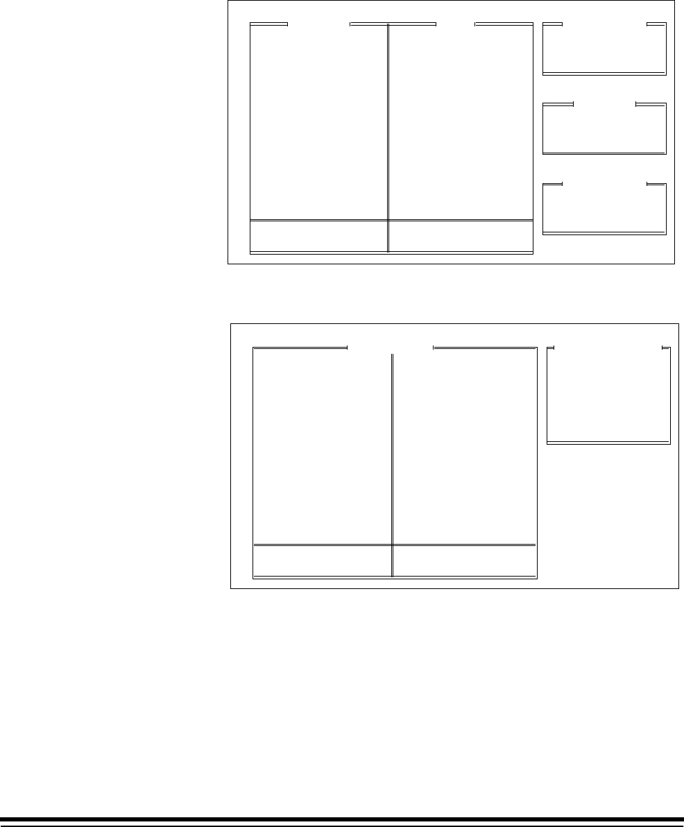
A-61097 May 1997 3-101
Document Sorter OFF
❏Microimager 70 ■Microimager 70/AFM ■Scanner 900
■Scanner 923 ■Scanner/Microimager 990 ■Scanner 9500
Select Document Sorter and the following screen appears:
Status
Error Response
Sort Criteria
Document Sorter
Sort Criteria
Don't Save & End Session
End Configuration
Save & End Session
Previous Menu
Mode Number: 10 Mode Name: MODE10
Default Stopper
Level 0 Docs
Level 1 Docs
Level 2 Docs
Level 3 Docs
Transfer Patch
Level III Patch
Level II Patch
Bar Code Docs
Partial Read BC
Docs w/o Bar Code
BC/Patch Docs
Skewed Documents
Length Error Docs
Upper
Default
Default
Default
Default
Default
Default
Default
Default
Default
Default
Default
Default
Default
Bin
Off or Disable
On or Enabled
Status
Display Only
Beep and Display
Stop and Display
Error Response
Select any of the Sort Criteria and the following screen appears:
Default Hopper
Lower Hopper
Upper Hopper
Previous Menu
Hopper Selection
Mode Configuration
Don't Save & End Session
End Configuration
Save & End Session
Previous Menu
Mode Number: 10 Mode Name: MODE10
MODE 10
3 Lvl
Supprs
4233
2112
None
Auto
Duplex
?????
1 Roll
Comic
Off
Off
Off
Xport
Off
Undef
Undef
Off
Off
Off
Lvl 2
Off
N N N
Off
On
Disply
Off
Off
Off
Off
No Sav
F
Mode Name
Index Format
IA Display Format
IA Field Widths
Level Rules
Batching
AEC Mode
Film Mode
Reduction Ratio
# of Cassettes
Film Writer
Image Mgmt Code
Length Monitor
Skew Monitor
Check Stacker
Endorser
Not Used
Ftswitch Pressed
Ftswitch Released
Ftswitch Cnf Tone
Patch Reader 1
Patch Reader 2
Patch Definition
Bar Code
Confirmation Tone
OCR Status
COIN User Channel
Printer Control
Primary DP-1
Secondary DP-1
Doc. Printer 12
Document Sorter
Mode Overrides
Film Definition
3-102 A-61097 May 1997
If 4 selections have been set and you choose a 5th option, the following
screen appears:
Maximum number of sorting
criteria has been reached
Press ENTER to proceed…
** ERROR **
Mode Configuration
Don't Save & End Session
End Configuration
Save & End Session
Previous Menu
Mode Number: 10 Mode Name: MODE10
MODE 10
3 Lvl
Supprs
4233
2112
None
Auto
Duplex
?????
1 Roll
Comic
Off
Off
Off
Xport
Off
Undef
Undef
Off
Off
Off
Lvl 2
Off
N N N
Off
On
Disply
Off
Off
Off
Off
No Sav
F
Mode Name
Index Format
IA Display Format
IA Field Widths
Level Rules
Batching
AEC Mode
Film Mode
Reduction Ratio
# of Cassettes
Film Writer
Image Mgmt Code
Length Monitor
Skew Monitor
Check Stacker
Endorser
Not Used
Ftswitch Pressed
Ftswitch Released
Ftswitch Cnf Tone
Patch Reader 1
Patch Reader 2
Patch Definition
Bar Code
Confirmation Tone
OCR Status
COIN User Channel
Printer Control
Primary DP-1
Secondary DP-1
Doc. Printer 12
Document Sorter
Mode Overrides
Film Definition
Mode Overrides
This mode enables or disables mode overrides. Enabling this option
means that permanent changes may be made to the original mode option
definitions using select function codes during operation. Disabling this
option means that changes made to the original mode option definitions
using select function codes during operation are temporary. The default
value is Discard Overrides.
■Microimager 70 ■Microimager 70/AFM ■Scanner 900
■Scanner 923 ■Scanner/Microimager 990 ■Scanner 9500
1. Select Mode Overrides.
Overrides
Mode Configuration
Don't Save & End Session
End Configuration
Save & End Session
Previous Menu
Mode Number: 10 Mode Name: MODE10
MODE 10
3 Lvl
Supprs
4233
2112
None
Auto
Duplex
?????
1 Roll
Comic
Off
Off
Off
Xport
Off
Undef
Undef
Off
Off
Off
Lvl 2
Off
N N N
Off
On
Disply
Off
Off
Off
Off
No Sav
F
Mode Name
Index Format
IA Display Format
IA Field Widths
Level Rules
Batching
AEC Mode
Film Mode
Reduction Ratio
# of Cassettes
Film Writer
Image Mgmt Code
Length Monitor
Skew Monitor
Check Stacker
Endorser
Not Used
Ftswitch Pressed
Ftswitch Released
Ftswitch Cnf Tone
Patch Reader 1
Patch Reader 2
Patch Definition
Bar Code
Confirmation Tone
OCR Status
COIN User Channel
Printer Control
Primary DP-1
Secondary DP-1
Doc. Printer 12
Document Sorter
Mode Overrides
Film Definition
Discard Overrides
Save Overrides
Previous Menu
2. Select the desired override option.

A-61097 May 1997 3-103
Film Definition
This mode enables or disables filming.
This option is set as follows:
Microimager 70 F (film)
Scanners 900, 923, 9500 NoF (no film)
Scanner/Microimager 990 F (film)
❏Microimager 70 ❏Microimager 70/AFM ❏Scanner 900
❏Scanner 923 ■Scanner/Microimager 990 ❏Scanner 9500
Mode Configuration
Don't Save & End Session
End Configuration
Save & End Session
Previous Menu
Mode Number: 10 Mode Name: MODE10
MODE 10
3 Lvl
Supprs
4233
2112
None
Auto
Duplex
?????
1 Roll
Comic
Off
Off
Off
Xport
Off
Undef
Undef
Off
Off
Off
Lvl 2
Off
N N N
Off
On
Disply
Off
Off
Off
Off
No Sav
F
Mode Name
Index Format
IA Display Format
IA Field Widths
Level Rules
Batching
AEC Mode
Film Mode
Reduction Ratio
# of Cassettes
Film Writer
Image Mgmt Code
Length Monitor
Skew Monitor
Check Stacker
Endorser
Not Used
Ftswitch Pressed
Ftswitch Released
Ftswitch Cnf Tone
Patch Reader 1
Patch Reader 2
Patch Definition
Bar Code
Confirmation Tone
OCR Status
COIN User Channel
Printer Control
Primary DP-1
Secondary DP-1
Doc. Printer 12
Document Sorter
Mode Overrides
Film Definition Filming Definition
Filming Enabled
Filming Disabled
Previous Menu

A-61097 May 1997 4-1
4 Installation Questionnaire
General Information
CUSTOMER NAME: __________________________________________________________________
CUSTOMER ADDRESS: _______________________________________________________________
__________________________________________________________________________________
CUSTOMER CONTACT: _________________________________PHONE: _______________________
SALES REPRESENTATIVE: ______________________________PHONE: _______________________
TRAINER:____________________________________________PHONE: _______________________
MACHINE ID NUMBER ______________
MODE
NUMBER/NAME APPLICATION(S)
1_____________________ ________________________________________________________
2_____________________ ________________________________________________________
3_____________________ ________________________________________________________
4_____________________ ________________________________________________________
5_____________________ ________________________________________________________
6_____________________ ________________________________________________________
7_____________________ ________________________________________________________
8_____________________ ________________________________________________________
9_____________________ ________________________________________________________
10_____________________ ________________________________________________________
11_____________________ ________________________________________________________
12_____________________ ________________________________________________________
13_____________________ ________________________________________________________
14_____________________ ________________________________________________________
15_____________________ ________________________________________________________
16_____________________ ________________________________________________________
17_____________________ ________________________________________________________
18_____________________ ________________________________________________________
4-2 A-61097 May 1997
Machine Definitions
0.0 Accessory Status
_____________ Adv. Doc. Controller
_____________ Bar Code Reader
_____________ Doc Scanning Array
_____________ Check Feeder
_____________ Check Stacker
_____________ Document Sorter
_____________ Endorser
_____________ Footswitch
_____________ Film Writing Module
_____________ Image Marker
_____________ Patch Reader 1
_____________ Patch Reader 2
_____________ Print Controller
_____________ Primary Doc Printer 1
_____________ Secondary Doc Printer 1
_____________ Doc Printer 12
_____________ OCR
__________ 1.0 Machine ID Number
__________ 2.0 Display Language
__________ 3.0 Measurement System
__________ 4.0 Programmable Function Keys
DefinitionKey
P1
P2
P3
P4
P5
P6
P7
P8
P9
P10
__________ 5.0 Date Format
____________Delimiter
__________ 6.0 Time Format
__________ 7.0 Alarm Tone
__________ 8.0 Confirmation Tones
9.0 Messages
DefinitionKey
0
1
2
3
4
5
6
7
8
9
Diagnostic Message - No entry Allowed.
10.0 Doc. Printer 12 Print Templates
(see next page)
__________ 11.0 Fixed Field Delimiter
__________ 12.0 System Clock
13.0 Version Numbers
___________ AEC
___________ BARCO
___________ FDS
___________ MCP
___________ OI
___________ PATCH
___________ DPC
___________ OCR
___________ SCSI
___________ U CAS
___________ L CAS
___________ LAPTOP
__________ 14.0 User COIN Port Protocol
User-defined:
___________ Baud Rate
___________ Parity Bit
___________ Character Length
___________ Handshaking
15.0 Custom Check Digit
___________ Attributes
___________ Constant 1
___________ Constant 2
___________ Divisor
___________ Left/Right
___________ LUT Status
___________ Lookup Table
__________ 16.0 Special Character Set
no entry 17.0 Save Config to PC
no entry 18.0 Load Config from PC
A-61097 May 1997 4-3
ITEM
1
2
3
4
5
6
7
8
9
10
11
12
LINE PRINT ITEM
Print Template #
ITEM
1
2
3
4
5
6
7
8
9
10
11
12
LINE PRINT ITEM
Print Template #
_
ITEM
1
2
3
4
5
6
7
8
9
10
11
12
LINE PRINT ITEM
Print Template #
ITEM
1
2
3
4
5
6
7
8
9
10
11
12
LINE PRINT ITEM
Print Template #
ITEM
1
2
3
4
5
6
7
8
9
10
11
12
LINE PRINT ITEM
Print Template #
_
ITEM
1
2
3
4
5
6
7
8
9
10
11
12
LINE PRINT ITEM
Print Template #
ITEM
1
2
3
4
5
6
7
8
9
10
11
12
LINE PRINT ITEM
Print Template #
ITEM
1
2
3
4
5
6
7
8
9
10
11
12
LINE PRINT ITEM
Print Template #
_
ITEM
1
2
3
4
5
6
7
8
9
10
11
12
LINE PRINT ITEM
Print Template #
ITEM
1
2
3
4
5
6
7
8
9
10
11
12
LINE PRINT ITEM
Print Template #

4-4 A-61097 May 1997
Mode Definitions MODE 1
❑Original Setup ❑Update (enter date) __________
Filename: _____________.cfg
May be linked with Mode(s): ________________
__________ 19.0 Mode Name
__________ 20.0 Index Format
__________ 21.0 Image Address Display Format
22.0 Image Address Field Widths
__________ Fixed Field
__________ Field C—Level 3
__________ Field B—Level 2
__________ Field A—Level 1
23.0 Level Rules
Level 0 followed by ___________
Level 1 followed by ___________
Level 2 followed by ___________
Level 3 followed by ___________
__________ 24.0 Batching
24.1 __________ Batch Level
24.2 __________ Batch Value
24.3 __________ Start of Batch
24.4 __________ End of Batch
__________ 25.0 AEC Mode
__________ 26.0 Film Mode
__________ 27.0 Reduction Ratio
__________ 28.0 Minimum Number of Cassettes
29.0 Film Writer
29.1 ________ Char Orientation
29.2 ________ IA Print Format
29.3 Write Definitions
____________ Level 0
____________ Level 1
____________ Level 2
____________ Level 3
30.0 Image Management Code
30.1 _______ Status
30.2 _______ Search Prog. #
30.3 _______ Magnification
30.4 _______ Splice Definition
30.5 _______ Image Mark Sizes
30.6 _______ Image Polarity
30.7 _______ Dup. Front Loc.
30.8 _______ Film Image Orien.
30.9 _______ Image Offset
31.1 Length Monitor
31.1 _______ Status
31.2 _______ Max. Doc. Length
31.3 _______ Min. Doc. Length
31.4 _______ Error Response
32.0 Skew Monitor
32.1 _______ Status
32.2 _______ Threshold
32.3 _______ Error Response
__________ 33.0 Check Stacker
34.0 Endorser
34.1 _______ Status
34.2 _______ Mode
34.3 _______ Print Position
__________ 35.0 Footswitch Pressed
__________ 36.0 Footswitch Released
__________ 37.0 Footswitch Confirmation Tone
__________ 38.0 Patch Reader 1
__________ 39.0 Patch Reader 2
40.0 Patch Definition
40.1 _______ Xfer Patch Def.
40.2 _______ Film Xfer Patch
40.3 _______ Patch Recognition
41.0 Bar Code
41.1 _______ Status
41.2 _______ Bar Code Type
41.3 _______ # of Characters
41.4 _______ Codes per Doc.
41.5 _______ Distance Between
41.6 _______ Scan Direction
41.7 _______ Image Processing
41.8 _______ Partial Read
41.9 _______ Min. Partial Char.
41.10_______ Patch Reading
41.11_______ Patch Location
41.12_______ End Fed Patch
41.13_______ Level Change
42.0 Confirmation Tones
42.1 _______ Patch Detected
42.2 _______ Bar Detected
42.3 _______ Bar Code/Patch
__________ 43.0 OCR Status

A-61097 May 1997 4-5
Mode Definitions MODE 1
44.0 COIN User Channel
44.1 Transmit Data
________ Level 0
________ Level 1
________ Level 2
________ Level 3
45.0 Printer Control
45.1 _______ IA Print Format
45.2 _______ Print Position
45.3 _______ Special Char Set
46.0 Primary Document Printer 1
46.1 _______ Status
46.2 _______ Font/Orientation
46.3 Print Definitions
________ Level 0
________ Level 1
________ Level 2
________ Level 3
47.0 Secondary Document Printer 1
47.1 _______ Status
47.2 _______ Font/Orientation
47.3 Print Definitions
________ Level 0
________ Level 1
________ Level 2
________ Level 3
48.0 Document Printer 12
48.1 _______ Status
48.2 _______ Font/Orientation
48.3 Print Definitions
________ Level 0
________ Level 1
________ Level 2
________ Level 3
49.0 Document Sorter
49.1 _______ Status
49.2 _______ Error Response
49.3 Sort Criteria
________ Default Hopper
________ Item 1/Location
________ Item 2/Location
________ Item 3/Location
__________ 50.0 Mode Overrides
__________ 51.0 Film Definition
A-61097 May 1997 A-1
A PPEN D IX A : System Map
Display Machine Accessories
Machine ID Number
Display Language
Measurement System
Programmable Function Keys
Date Format
Time Format
Alarm Tone
Doc Printer/Film Writer Msg
DP-12 Print Template
Fixed Field Delimiter
Set System Clock
Version Numbers
User COIN Port Protocol
Custom Check Digit
OI Hardware Character Set
Save to PC
Load from PC
Mode Configuration
End Session
MACHINE STATE
Mainframe Configuration
Define Mode 1
Define Mode 2
Define Mode 3
Define Mode 4
Define Mode 5
Define Mode 6
Define Mode 7
Define Mode 8
Define Mode 9
Define Mode 10
Define Mode 11
Define Mode 12
Define Mode 13
Define Mode 14
Define Mode 15
Define Mode 16
Define Mode 17
Define Mode 18
Mode Configuration
Mode to Mode Copy
End Session
Previous Menu
MODE 10
3 Lvl
Supprs
4233
2112
None
Auto
Duplex
?????
1 Roll
Comic
Off
Off
Off
Xport
Off
Undef
Undef
Off
Off
Off
Lvl 2
On
N N N
Off
On
Disply
Off
Off
Off
Off
No Sav
F
Mode Name
Index Format
IA Display Format
IA Field Widths
Level Rules
Batching
AEC Mode
Film Mode
Reduction Ratio
# of Cassettes
Film Writer
Image Mgmt Code
Length Monitor
Skew Monitor
Check Stacker
Endorser
Not Used
Ftswitch Pressed
Ftswitch Released
Ftswitch Cnf Tone
Patch Reader 1
Patch Reader 2
Patch Definition
Bar Code
Confirmation Tone
OCR Status
COIN User Channel
Printer Control
Primary DP-1
Secondary DP-1
Doc. Printer 12
Document Sorter
Mode Overrides
Film Definition
Mode Configuration
Don't Save & End Session
End Configuration
Save & End Session
Previous Menu
Mode Number: 10 Mode Name: MODE10
A-2 A-61097 May 1997
Mode to Mode Copy
Mode Number: 10 Mode Name: MODE10
Copy Mode 1
Copy Mode 2
Copy Mode 3
Copy Mode 4
Copy Mode 5
Copy Mode 6
Copy Mode 7
Copy Mode 8
Copy Mode 9
Copy Mode 10
Copy Mode 11
Copy Mode 12
Copy Mode 13
Copy Mode 14
Copy Mode 15
Copy Mode 16
Copy Mode 17
Copy Mode 18
Previous Menu
Copy From Mode:
Copy From
Mode:
Select Mode to Copy From
Copy Mode 1
Copy Mode 2
Copy Mode 3
Copy Mode 4
Copy Mode 5
Copy Mode 6
Copy Mode 7
Copy Mode 8
Copy Mode 9
Copy Mode 10
Copy Mode 11
Copy Mode 12
Copy Mode 13
Copy Mode 14
Copy Mode 15
Copy Mode 16
Copy Mode 17
Copy Mode 18
Previous Menu
Copy To Mode:
Copy Mode 1
Copy Mode 2
Copy Mode 3
Copy Mode 4
Copy Mode 5
Copy Mode 6
Copy Mode 7
Copy Mode 8
Copy Mode 9
Copy Mode 10
Copy Mode 11
Copy Mode 12
Copy Mode 13
Copy Mode 14
Copy Mode 15
Copy Mode 16
Copy Mode 17
Copy Mode 18
Previous Menu
Copy From Mode:
Mode to Mode Copy
Mode Number: 10 Mode Name: MODE10
Select Copy to Mode 2
01
Copy From
Mode:
Mode to Mode Copy
Mode Number: 10 Mode Name: MODE10
Are you sure
you want to
do this?
All data in
the copied
mode will
be lost!
Previous Menu
Copy to Mode
Select Copy to Mode
01 02
Copy To
Mode:
Downloading Mode Configuration Mainframe
Send Mode Configuration to Mainframe
Copy From
Mode:
†May be executed while transport is running.
* Available when filming; for use only with Microimager 70 (with or without AFM), and
Scanner/Microimager 990.
** Available when scanning; for use only with the Scanner 900, Scanner 923, Scanner 9500, and
Scanner/Microimager 990.
*** Available when using advanced capabilities; for use only with the Microimager 70 (with AFM),
Scanner 900, Scanner 923, Scanner 9500, and Scanner/Microimager 990.
A-61097 May 1997 B-1
A PPEN D IX B : Function Codes
P-Key Definition Input
Code Function Code Name/Description Required Optional
F01 Select Mode
Allows you to select one of the eighteen (18)
application modes.
f01 ,xx 2-digit mode number
F02 Restore Mode
Allows you to restore the current application mode to
its default status (as it was defined at installation),
provided that mode overrides are not saved.
f02
F03* Filming Only
Allows you to film documents, with no level counting,
endorsing, patch reading, etc.
f03 ,0 off/disable
,1 on/enable
,2 toggle
F04 Counting Only
Allows you to count documents only, with no filming,
scanning, etc.
f04 ,0 off/disable
,1 on/enable
,2 toggle
F05†Accessory Status
Allows you to display the current status of each
accessory installed.
f05
F06†Terminate Batch
Allows you to prematurely end a batch f06
F07†Level 0
Allows you to assign Level 0 to the next document
fed into the transport.
f07
F08†Last Image Address
Allows you to display the Image Address of the last
document processed.
f08
F09†Total Document Count
Allows you to display the total number of documents
processed. Also allows you to reset the count to zero.
f09
F10†Level 0 Count
Allows you to display the total number of documents
assigned Level 0. Also allows you to reset the count
to zero.
f10
F11†Level 1 Count
Allows you to display the total number of documents
assigned Level 1. Also allows you to reset the count
to zero.
f11
†May be executed while transport is running.
* Available when filming; for use only with Microimager 70 (with or without AFM), and
Scanner/Microimager 990.
** Available when scanning; for use only with the Scanner 900, Scanner 923, Scanner 9500, and
Scanner/Microimager 990.
*** Available when using advanced capabilities; for use only with the Microimager 70 (with AFM),
Scanner 900, Scanner 923, Scanner 9500, and Scanner/Microimager 990.
B-2 A-61097 May 1997
P-Key Definition Input
Code Function Code Name/Description Required Optional
F12†Level 2 Count
Allows you to display the total number of documents
assigned Level 2. Also allows you to reset the count
to zero.
f12
F13†Level 3 Count
Allows you to display the total number of documents
assigned Level 3. Also allows you to reset the count
to zero.
f13
F14 Reset Level Counts
Allows you to reset all counters (Level 0, Level 1,
Level 2, Level 3, and Total) to zero.
f14
F15 Alarm Volume
Allows you to adjust the volume of the alarm. f15
F16 Alarm Tone
Allows you to adjust the pitch of the alarm tone. f16
F17†Elapsed Time
Allows you to display the number of hours the motor,
transport, and AC have been running, in addition to
the non-resettable document count.
f17
F18 Display Contrast
Allows you to adjust the contrast of the Status
Display.
f18
F19 Display Language
Allows you to choose the language in which the
Status Display messages will appear.
f19
F20 Measurement System
Allows you to choose the measurement system in
which measurements are displayed.
f20
F21*** Change Time
Allows you to change the time. f21
F22*** Change Date
Allows you to change the date. f22
F23†*** Time and Date Display
Allows you to view the current time and date. f23
F24* AEC On/Off
Allows you to turn the Automatic Exposure Control on
or off.
f24 ,0 off/disabled
,1 on/enabled
F25* AEC Auto Adjust
Allows you to adjust the AEC exposure setting when
the AEC is in Auto Mode (ON).
f25
†May be executed while transport is running.
* Available when filming; for use only with Microimager 70 (with or without AFM), and
Scanner/Microimager 990.
** Available when scanning; for use only with the Scanner 900, Scanner 923, Scanner 9500, and
Scanner/Microimager 990.
*** Available when using advanced capabilities; for use only with the Microimager 70 (with AFM),
Scanner 900, Scanner 923, Scanner 9500, and Scanner/Microimager 990.
A-61097 May 1997 B-3
P-Key Definition Input
Code Function Code Name/Description Required Optional
F26* AEC Fixed Adjust
Allows you to adjust the AEC exposure setting when
the AEC is in Fixed Mode (OFF).
f26
F27†* Film Advance
Allows you to advance the film in six (6) inch [150
mm] increments, or by a specific amount input in
inches or millimetres.
f27
F28†* Film Leader
Allows you to create a film leader which is six (6) feet
[1.8 metres] of blank film.
f28
F29* Advance Film to End of Roll
Allows you to advance the film to the end of the roll. f29
F30* Display Film Remaining
Allows you to display the amount of film remaining in
each film cassette.
f30
F31* Lead End Code
Allows you to create a lead end code for retrieval
purposes.
f31
F32* Trail End Code
Allows you to create a trail end code for retrieval
purposes.
f32
F33* Roll Number
Allows you to display the current roll number and/or
change to a new roll number.
f33
F34 Operator ID Number
Allows you to display the current operator ID number
and/or change to a new operator ID number.
f34
F35* Cassette ID Number
Allows you to display the current cassette ID number
and/or change to a new cassette ID number.
f35
F37** Scanner Calibration
Allows you to initiate the calibration process required
before scanning documents.
f37
F38** Scanner End-of-Job
Allows you to signal the host computer that the last
document of the job has been fed into the transport.
f38
F39 Printer Character Shift
Allows you to select which set of ink jets will be used
to print each character.
f39
F40 All Document Printers On/Off
Allows you to turn all document printers (primary
DP1, secondary DP1, and DP12) on or off.
f40 ,0 off/disable
,1 on/enable
†May be executed while transport is running.
* Available when filming; for use only with Microimager 70 (with or without AFM), and
Scanner/Microimager 990.
** Available when scanning; for use only with the Scanner 900, Scanner 923, Scanner 9500, and
Scanner/Microimager 990.
*** Available when using advanced capabilities; for use only with the Microimager 70 (with AFM),
Scanner 900, Scanner 923, Scanner 9500, and Scanner/Microimager 990.
B-4 A-61097 May 1997
P-Key Definition Input
Code Function Code Name/Description Required Optional
F41 Primary DP1 On/Off
Allows you to turn the primary document printer 1 on
or off.
f41 ,0 off/disable
,1 on/enable
F42*** Secondary DP1 On/Off
Allows you to turn the secondary document printer 1
on or off.
f42 ,0 off/disable
,1 on/enable
F43 Document Printer 12 On/Off
Allows you to turn the document printer 12 on or off. f43 ,0 off/disable
,1 on/enable
F44†Omit Printing on Next Document Only
Allows you to omit printing by all document printers
on the next document only.
f44
F45 Print Test
Allows you to test the position and print quality of all
document printers installed.
f45
F46 Print Position
Allows you to specify how far from the leading edge
of the document all document printers will print.
f46
F49 Purge Frequency
Allows you to specify how often, in terms of the
number of documents fed into the transport, a
priming ink spurt is initiated.
f49
F50 Patch Reader 1 On/Off
Allows you to turn the primary patch reader on or off. f50 ,0 off/disable
,1 on/enable
F51*** Patch Reader 2 On/Off
Allows you to turn the secondary patch reader on or
off.
f51 ,0 off/disable
,1 on/enable
F52*** End Fed Patch Reading On/Off
Allows you to turn end fed patch reading on or off. f52 ,0 off/disable
,1 on/enable
F53*** Patch Reading Confirmation Tone
Allows you to turn the patch reading confirmation
tone on or off.
f53 ,0 off/disable
,1 on/enable
F54†Omit Patch Reading on Next Document Only
Allows you to omit patch reading on the next
document only.
f54
F56 Printer Open Jet Test
Allows you to determine whether or not there are
non-functional ink jets in the Document Printer 12 ink
cartridge.
f56
F57 Endorser On/Off
Allows you to turn the endorser on or off. f57 ,0 off/disable
,1 on/enable
F58 Endorser Mode
Allows you to display the current endorser mode
and/or change the endorser mode.
f58
†May be executed while transport is running.
* Available when filming; for use only with Microimager 70 (with or without AFM), and
Scanner/Microimager 990.
** Available when scanning; for use only with the Scanner 900, Scanner 923, Scanner 9500, and
Scanner/Microimager 990.
*** Available when using advanced capabilities; for use only with the Microimager 70 (with AFM),
Scanner 900, Scanner 923, Scanner 9500, and Scanner/Microimager 990.
A-61097 May 1997 B-5
P-Key Definition Input
Code Function Code Name/Description Required Optional
F59 Endorser Print Position
Allows you to specify how far from the leading edge
of the document the endorsement will appear.
f59
F60*** Bar Code Reading 1 On/Off
Allows you to turn bar code reading on or off. f60 ,0 off/disable
,1 on/enable
F62*** Bar Code/Patch Reading Confirmation Tone
Allows you to turn the bar code/patch reading
confirmation tone on or off.
f62 ,0 off/disable
,1 on/enable
F63*** Bar Code Reading Confirmation Tone
Allows you to turn the bar code reading confirmation
tone on or off.
f63 ,0 off/disable
,1 on/enable
F64†*** Omit Bar Code Reading on Next Document Only
Allows you to omit bar code reading on the next
document only.
f64
F65*** Bar Code Test
Allows you to perform a test to verify the operation of
the bar code reader.
f65
F66*** Partial Bar Code Reading On/Off
Allows you to turn partial bar code reading on or off. f66 ,0 off/disable
,1 on/enable
F70 Length Checking On/Off
Allows you to turn length checking on or off. f70 ,0 off/disable
,1 on/enable
F71†Omit Length Checking On Next Document Only
Allows you to omit length checking on the next
document only.
f71
F72 Skew Detection
Allows you to turn skew detection on or off. f72 ,0 off/disable
,1 on/enable
F73** Latched Scanning Flag
Allows you to set a flag which alerts the host system
that the document, and those which follow, are of
special interest. The flag will remain activated for
every document until it is turned off.
f73
F74** Momentary Scanning Flag
Allows you to set a flag which alerts the host system
that the next document only is of special interest.
f74
F75*** Footswitch Confirmation Tone
Allows you to turn the footswitch confirmation tone on
or off.
f75 ,0 off/disable
,1 on/enable
†May be executed while transport is running.
* Available when filming; for use only with Microimager 70 (with or without AFM), and
Scanner/Microimager 990.
** Available when scanning; for use only with the Scanner 900, Scanner 923, Scanner 9500, and
Scanner/Microimager 990.
*** Available when using advanced capabilities; for use only with the Microimager 70 (with AFM),
Scanner 900, Scanner 923, Scanner 9500, and Scanner/Microimager 990.
‡Available when using advanced capabilities; for use only with the Microimager 70 (with AFM),
Scanner 900, Scanner 923, and Scanner/Microimager 990.
B-6 A-61097 May 1997
P-Key Definition Input
Code Function Code Name/Description Required Optional
F76‡OCR On/Off
Allows you to turn OCR on or off. f76 ,0 off/disable
,1 on/enable
F80 Document Sorter On/Off
Allows you to turn the document sorter on or off. f80 ,0 off/disable
,1 on/enable
F81†Sort Next Document to Specified Hopper
Allows you to specify the hopper (default, upper, or
lower) in which the next document only will be
deposited.
f81
F82†Sort All Documents to Specified Hopper
Allows you to specify the hopper (default, upper, or
lower) in which all documents will be deposited. This
definition will remain in effect for every document
until it is redefined.
f82
F91 Select Linked Mode
Allows you to switch from one application mode to
another, keeping the last Image Address.
f91
F92 Fixed Field
Allows you to enter a new fixed field value, containing
alphanumeric characters.
f92
F93*** Action/Confirmation Tone
Allows you to adjust the pitch of the
action/confirmation tone.
f93
F94†Level 1
Allows you to assign Level 1 to the next document
fed into the transport.
f94
F95†Level 2
Allows you to assign Level 2 to the next document
fed into the transport.
f95
F96†Level 3
Allows you to assign Level 3 to the next document
fed into the transport.
f96
F97 Next Image Address
Allows you to input the next Image Address. f97
F98†Stop
Allows you to stop the transport. f98
F99 Run
Allows you to turn on the transport. f99
A-61097 May 1997 C-1
A PPEN D IX C : Recommended Entries
Item Description Values
0.0 Accessory Status PRES (Present)
NOTPRES (Not Present)
1.0 Machine ID Number 00 – 99
2.0 Display Language ENG (English)
FREN (French)
GERM (German)
ITAL (Italian)
SPAN (Spanish)
3.0 Measurement
System ENG (English)
MET (Metric)
4.0 Programmable
Function Keys Enter function(s)
5.0 Date Format mmddyy
mmdd
ddmmmyy
ddmmm
mmyy
yddd
yyddd
yymmdd
ddmmyy
mmmddyyyy
Date Delimiter Slash (/)
Dash (–)
Period (.)
Space ( )
No Del
6.0 Time Format 12 hr AM/PM
12 hr
24 hr
7.0 Alarm Tone High
Low
8.0 Confirmation Tones ON (Enabled)
OFF (Disabled)
9.0 Messages Enter messages
10.0 Doc. Printer 12
Print Templates Enter line number and
print item(s)
11.0 Fixed Field Delimiter Slash (/)
Dash (–)
Period (.)
Space ( )
Backslash (\)
12.0 System Clock TERM (Terminal time)
MAN (Manual)
13.0 Version Numbers Enter version numbers
Item Description Values
14.0 User COIN Port
Protocol NO (Not used)
YES (Used)
Baud rate 300
600
1200
2400
4800
9600
19.2 K
Parity Bit NONE (No parity)
ODD (Odd parity)
EVEN (Even parity)
Character Length 7 (7 Bits)
8 (8 Bits)
Handshaking None
CTS/RTS
15.0 Custom Check
Digit NO (Not used)
YES (Used)
Attributes 11-digit string
Constant 1 2-digit number
Constant 2 2-digit number
Divisor 2-digit number
Left/Right LEFT (Left of decimal)
RIGHT (Right of decimal)
LUT Status NO (not used)
YES (used)
Lookup Table 11-digit string
16.0 Special Character
Set JAP (Japanese)
EURO (European)
17.0 Save Config to PC no entry required
18.0 Load Config from
PC no entry required
19.0 Mode Name 10-digit string
20.0 Index Format 1 (Single level)
2 (Two level)
2Off (Two level offset)
3 (Three level)
3Off (Three level offset)
21.0 Image Address
Display Format DISP (Display)
SUPP (Suppress)
COMP (Compress)
C-2 A-61097 May 1997
Item Description Values
22.0 Image Address
Field Widths 0 – 9
23.0 Level Rules Level 0
Level 1
Level 2
Level 3
24.0 Batching
24.1 Level None
Level 1
Level 2
Level 3
24.2 Value 01 – 9999
24.3 Start-of-Batch
function f94 (go to Level 1)
f95 (go to Level 2)
f96 (go to Level 3)
24.4 End-of-Batch
function f94 (go to Level 1)
f95 (go to Level 2)
f96 (go to Level 3)
f98 (stop)
25.0 AEC Mode Auto
Fixed
26.0 Film Mode SIM (Simplex)
DUP (Duplex)
DUO (Duo)
27.0 Reduction Ratio Don’t Care
24X
40X
50X
28.0 Minimum Number
of Cassettes One
Two
29.0 Film Writer
29.1 Character
Orientation Com (Comic)
CIN (Cine)
COM180 (Comic 180)
CIN180 (Cine 180)
29.2 Image Addres
Display Format DISP (Display)
SUPP (Suppress)
COMP (Compress)
29.3 Write Definitions Enter item(s)
30.0 Image
Management Code
30.1 Status ON (Enabled)
OFF (Disabled)
30.2 Search Program
Number 00 – 70
30.3 Magnification 20 – 80
30.4 Splice Definition Ignore
Level 1
Level 2
Level 3
Item Description Values
30.5 Image Mark Sizes CUST (Custom)
KOD (Kodak Standard)
30.6 Image Polarity OPP (Opposite of IM)
SAME (Same as IM)
30.7 Duplex Front
Location OPP (Opposite of channel)
SAME (Same as channel)
30.8 Film Image
Orientation DN (Leading Edge down)
UP (Leading Edge up)
30.9 Image Offset 000 – 127
31.0 Length Monitor
31.1 Status ON (Enabled)
OFF (Disabled)
31.2 Maximum
Document Length 02.5000 – 75.000 in.
63.5 – 1905 mm on IL70
63.5 – 508 on others
31.3 Minimum
Document Length 02.500 – 13.000 in.
63.5 – 330.2 mm
31.4 Error Response DISP (Display)
BEEP (Display and Beep)
STOP (Stop and Display)
32.0 Skew Monitor
32.1 Status ON (Enabled)
OFF (Disabled)
32.2 Threshold 5 (5 degrees)
10 (10 degrees)
32.3 Error Response DISP (Display)
BEEP (Display and Beep)
STOP (Stop and Display)
33.0 Chek Stacker ON (Enabled)
OFF (Disabled)
34.0 Endorser
34.1 Status ON (Enabled)
OFF (Disabled)
34.2 Mode CON (Continuous)
SIN (Single Stamp)
34.3 Print Position 00.000 – 70.000 in.
0 – 1778 mm
Not Used
35.0 Footswitch Pressed OFF (Undefined)
Level 0
Level 1
Level 2
Level 3
INC (Increment)
SLevel 0 (Sustained)
SLevel 1 (Sustained)
SLevel 2 (Sustained)
SLevel 3 (Sustained)
F Key
P Key
A-61097 May 1997 C-3
Item Description Values
36.0 Footswitch
Released OFF (Undefined)
Level 0
Level 1
Level 2
Level 3
INC (Increment)
37.0 Footswitch
Confirmation Tone ON (Enabled)
OFF (Disabled)
38.0 Patch Reader 1 ON (Enabled)
OFF (Disabled)
39.0 Patch Reader 2 ON (Enabled)
OFF (Disabled)
40.0 Patch Definition
40.1 Transfer Patch
Definition Level 1
Level 2
Level 3
None
40.2 Film Transfer Patch NO (not filmed)
YES (filmed)
40.3 Patch Recognition 2 (Type 2)
3 (Type 3)
XFER (Transfer)
2/3 (Types 2 and 3)
2X (Types 2 and Transfer)
3X (Types 3 and Transfer)
ALL (All types)
41.0 Bar Code
41.1 Status ON (Enabled)
OFF (Disabled)
41.2 Bar Code Type 3 of 9 (Code 39)
2 of 5 (Interleaved 2 of 5)
CODA (Codabar)
41.3 Number of
Characters 03 – 80
41.4 Codes per
Document ONE ALL
41.5 Distance Between
Codes 0.375 – 3.000 in.
09.53 – 76.20 mm
41.6 Scan Direction UNI (Uni-directional)
BI (Bi-directional)
41.7 Image Processing ON (Enabled)
OFF (Disabled)
41.8 Partial Read ON (Enabled)
OFF (Disabled)
41.9 Minimum Partial
Read Characters 03 – 80
41.10 Patch Reading ON (Enabled)
OFF (Disabled)
41.11 Patch Location 1.92 – 9.60 in.
048.77 – 243.84 mm
Item Description Values
41.12 End Fed Patch ON (Enabled)
OFF (Disabled)
41.13 Level Change Level 0
Level 1
Level 2
Level 3
OFF (Undefined)
42.0 Confirmation Tones
42.1 Patch Detected
42.2 Bar Code Detected ON (Enabled)
OFF (Disabled)
42.3 Bar Code/Patch
Detected
43.0 OCR Status ON (Enabled)
OFF (Disabled)
44.0 COIN User
Channel NO (Not used)
YES (Used)
44.1 Transmit Data Enter data
45.0 Print Controller
45.1 Image Address
Print Format DISP (Display)
COMP (Compress)
SUPP (Suppress)
45.2 Print Position 00.125 – 75.000 in.
3 – 1778 mm
45.3 Special Character
Set SM (Smaller font)
LG (Larger font)
46.0 Primary Document
Printer 1
46.1 Status ON (Enabled)
OFF (Disabled)
46.2 Font/Orientation SCOM (Sm Comic)
SCIN (Sm Cine)
SCOM180 (Sm Comic180)
SCIN180 (Sm Cine180)
LCOM (Lg Comic)
LCIN (Lg Cine)
LOM180 (Lg Comic 180)
LCIN180 (Lg Cine 180)
46.3 Print Definitions Enter item(s)
47.0 Secondary
Document Printer 1
47.1 Status ON (Enabled)
OFF (Disabled)
47.2 Font/Orientation SCOM (Sm Comic)
SCIN (Sm Cine)
SCOM180 (Sm Comic 180)
SCIN180 (Sm Cine180)
LCOM (Lg Comic)
LCIN (Lg Cine)
LCOM180 (Lg Comic180)
LCIN180 (Lg Cine180)

C-4 A-61097 May 1997
Item Description Values
47.3 Print Definitions Enter item(s)
48.0 Document
Printer 12
48.1 Status ON (Enabled)
OFF (Disabled)
48.2 Font/Orientation COM (Comic)
COM180 (Comic 180)
48.3 Print Definitions Enter template
49.0 Document Sorter
49.1 Status ON (Enabled)
OFF (Disabled)
49.2 Error Response DISP (Display)
BEEP (Display and Beep)
Stop (Stop and Display)
49.3 Sort Criteria Enter selected criteria
and bin
50.0 Mode Overrides DIS (Discard)
SAV (Save)
51.0 Film Definition Filming Enabled
Filming Disabled

EASTMAN KODAK COMPANY
Business Imaging Systems
Rochester, New York 14650
Kodak, Digital Science, the ds monogram symbol,
and Imagelink are trademarks of Eastman Kodak
Company.
Printed on recycled paper.
BUSINESS
IMAGING
SYSTEMS
A-61097 5/97
©Eastman Kodak Company, 1997
Printed in U.S.A.
