Kohler 100Efoz 125Eoz Users Manual Kfc
23EFOZ28EOZ to the manual 5c7f0fd8-af57-4032-ab34-3aaba29f438e
2015-01-21
: Kohler Kohler-100Efoz-125Eoz-Users-Manual-220075 kohler-100efoz-125eoz-users-manual-220075 kohler pdf
Open the PDF directly: View PDF ![]() .
.
Page Count: 92
Marine Generator Sets
TP-6069 6/03d
Installation
Models:
3.5EFOZ/4EOZ, 4EFOZ/5EOZ
6.5EFOZ/8EOZ, 8.5EFOZ, 9EFOZ/10EOZ
11EFOZ/13EOZ, 11.5EFOZ/14EOZ
13EFOZ/15.5EOZ, 16EFOZ/20EOZ
17.5EFOZ/20EOZ, 19EFOZ/23EOZ
20EFOZ/24EOZ, 23EFOZ/28EOZ
27EFOZ/32EOZ, 33EFOZ/40EOZ
40EFOZ/50EOZ, 55EFOZ/65EOZ
70EFOZ/80EOZ, 80EFOZ/99EOZ
100EFOZ/125EOZ, 125EFOZ/150EOZ

TP-6069 6/03 Table of Contents
Table of Contents
Safety Precautions and Instructions I........................................................
Section 1 Introduction 1.....................................................................
Section 2 Location and Mounting 3..........................................................
2.1 General Considerations 3................................................
2.2 Location 3.............................................................
2.3 Mounting 3.............................................................
Section 3 Cooling System 5.................................................................
3.1 Ventilation 5............................................................
3.2 Cooling System Components 5...........................................
3.2.1 Intake Through-Hull Strainer (Seacock Cover) 5.....................
3.2.2 Seacock 6.....................................................
3.2.3 Seawater Strainer 6.............................................
3.2.4 Water Lines 6..................................................
3.2.5 Closed Heat Exchanger (4--125EFOZ/5--150EOZ Models) 6..........
3.2.6 Direct Water Cooled (3.5EFOZ/4EOZ Models) 6.....................
Section 4 Exhaust System 11.................................................................
4.1 Types 11...............................................................
4.2 Exhaust Lines 11........................................................
4.3 Exhaust System Location, Mounting, and Installation 12.......................
4.3.1 Above-Waterline Installation 12....................................
4.3.2 Mid/Below-Waterline Installation 14.................................
Section 5 Fuel System 17.....................................................................
5.1 Fuel Tank 17............................................................
5.2 Fuel Lines 18............................................................
5.3 Fuel Filters 18...........................................................
5.4 Fuel Pump Lift 18........................................................
5.5 Fuel Consumption 18.....................................................
Section 6 Electrical System 19................................................................
6.1 AC Voltage Connections 19...............................................
6.2 Circuit Protection 19......................................................
6.2.1 Circuit Breaker Considerations 19..................................
6.2.2 Circuit Breaker Installation (4--27EFOZ and 5--32EOZ Models) 21......
6.2.3 Circuit Breaker Installation (33--125EFOZ and 40--150EOZ Models) 22..
6.3 Installation In Steel or Aluminum Vessels 23.................................
6.4 Installation Recommendations 23..........................................
6.5 Battery 24...............................................................
6.6 Wiring 24...............................................................
6.7 Remote Start Switch Connection 25........................................
Section 7 Installation Drawings 29............................................................
Section 8 Reconnection/Adjustments 67.......................................................
8.1 Four-Lead Reconnection 67...............................................
8.1.1 100--120-Volt Configurations 67....................................
8.1.2 100--120/200--240-Volt Configurations 67............................
8.1.3 200--240-Volt Configurations 68....................................
8.2 Twelve-Lead Reconnection 68.............................................
8.3 Decision-Maker 3+ Controller Overvoltage Shutdown Adjustment 69............
8.4 Voltage Regulator Adjustment (4--27EFOZ and 5--32EOZ Models) 72...........
Appendix A Generator Selection and Wattage Requirements A-1................................
Appendix B Abbreviations A-2................................................................
Appendix C Generator Set Output Ratings Procedure A-4.......................................
TP-6069 6/03 ISafety Precautions and Instructions
Safety Precautions and Instructions
IMPORTANT SAFETY
INSTRUCTIONS. Electromechanical
equipment, including generator sets,
transfer switches, switchgear, and
accessories, can cause bodily harm
and pose life-threatening danger when
improperly installed, operated, or
maintained. To prevent accidents be
aware of potential dangers and act
safely. Read and follow all safety
precautions and instructions. SAVE
THESE INSTRUCTIONS.
This manual has several types of safety
precautions and instructions: Danger,
Warning, Caution, and Notice.
DANGER
Danger indicates the presence of a
hazard that will cause severe
personal injury, death,orsubstantial
property damage.
WARNING
Warning indicates the presence of a
hazard that can cause severe
personal injury, death, or substantial
property damage.
CAUTION
Caution indicates the presence of a
hazard that will or can cause minor
personal injury or property damage.
NOTICE
Notice communicates installation,
operation, or maintenance information
that is safety related but not hazard
related.
Safety decals affixed to the equipment
in prominent places alert the operator
or service technician to potential
hazards and explain how to act safely.
The decals are shown throughout this
publication to improve operator
recognition. Replace missing or
damaged decals.
Accidental Starting
Accidental starting.
Can cause severe injury or death.
Disconnect the battery cables before
working on the generator set.
Remove the negative (--) lead first
when disconnecting the battery.
Reconnect the negative (--) lead last
when reconnecting the battery.
WARNING
Disabling the generator set.
Accidental starting can cause
severe injury or death. Before
working on the generator set or
connected equipment, disable the
generator set as follows: (1) Move the
generator set master switch to the OFF
position. (2) Disconnect the power to
the battery charger. (3) Remove the
battery cables, negative (--) lead first.
Reconnect the negative (--) lead last
when reconnecting the battery. Follow
these precautions to prevent starting of
the generator set by an automatic
transfer switch, remote start/stop
switch, or engine start command from a
remote computer.
Disabling the generator set.
Accidental starting can cause
severe injury or death. Before
working on the generator set or
equipment connected to the set,
disable the generator set as follows:
(1) Place the generator set start/stop
switch in the STOP position.
(2) Disconnect the power to the battery
charger, if equipped. (3) Remove the
battery cables, negative (--) lead first.
Reconnect the negative (--) lead last
when reconnecting the battery. Follow
these precautions to prevent the
starting of the generator set by the
remote start/stop switch.
Disabling the generator set.
Accidental starting can cause
severe injury or death. Before
working on the generator set or
equipment connected to the set,
disable the generator set as follows:
(1) Press the generator set on/off
button to shut down the generator set.
All indicator lamps dim. (2) Disconnect
the power to the battery charger, if
equipped. (3) Remove the battery
cables, negative (--) lead first.
Reconnect the negative (--) lead last
when reconnecting the battery. Follow
these precautions to prevent the
starting of the generator set by the
remote start/stop switch.
Battery
Sulfuric acid in batteries.
Can cause severe injury or death.
Wear protective goggles and clothing.
Battery acid may cause blindness and
burn skin.
WARNING
Battery electrolyte is a diluted
sulfuric acid. Battery acid can cause
severe injury or death. Battery acid
can cause blindness and burn skin.
Always wear splashproof safety
goggles, rubber gloves, and boots
when servicing the battery. Do not
open a sealed battery or mutilate the
battery case. If battery acid splashes in
the eyes or on the skin, immediately
flush the affected area for 15 minutes
with large quantities of clean water.
Seek immediate medical aid in the case
of eye contact. Never add acid to a
battery after placing the battery in
service, as this may result in hazardous
spattering of battery acid.
TP-6069 6/03II Safety Precautions and Instructions
Battery acid cleanup. Battery acid
can cause severe injury or death.
Battery acid is electrically conductive
and corrosive. Add 500 g (1 lb.) of
bicarbonate of soda (baking soda) to a
containerwith4L(1gal.)ofwaterand
mix the neutralizing solution. Pour the
neutralizing solution on the spilled
battery acid and continue to add the
neutralizing solution to the spilled
battery acid until all evidence of a
chemical reaction (foaming) has
ceased. Flush the resulting liquid with
water and dry the area.
Battery gases. Explosion can cause
severe injury or death. Battery gases
can cause an explosion. Do not smoke
or permit flames or sparks to occur near
a battery at any time, particularly when
it is charging. Do not dispose of a
battery in a fire. To prevent burns and
sparks that could cause an explosion,
avoid touching the battery terminals
with tools or other metal objects.
Remove all jewelry before servicing the
equipment. Discharge static electricity
from your body before touching
batteries by first touching a grounded
metal surface away from the battery. To
avoid sparks, do not disturb the battery
charger connections while the battery
is charging. Always turn the battery
charger off before disconnecting the
battery connections. Ventilate the
compartments containing batteries to
prevent accumulation of explosive
gases.
Battery short circuits. Explosion
can cause severe injury or death.
Short circuits can cause bodily injury
and/or equipment damage.
Disconnect the battery before
generator set installation or
maintenance. Remove all jewelry
before servicing the equipment. Use
tools with insulated handles. Remove
the negative (--) lead first when
disconnecting the battery. Reconnect
the negative (--) lead last when
reconnecting the battery. Never
connect the negative (--) battery cable
to the positive (+) connection terminal
of the starter solenoid. Do not test the
battery condition by shorting the
terminals together.
Engine Backfire/Flash
Fire
Fire.
Can cause severe injury or death.
Do not smoke or permit flames or sparks
near fuels or the fuel system.
WARNING
Servicing the fuel system. A flash
fire can cause severe injury or death.
Do not smoke or permit flames or
sparks near the carburetor, fuel line,
fuel filter, fuel pump, or other potential
sources of spilled fuels or fuel vapors.
Catch fuels in an approved container
when removing the fuel line or
carburetor.
Servicing the air cleaner. A sudden
backfire can cause severe injury or
death. Do not operate the generator
set with the air cleaner/silencer
removed.
Combustible materials. A sudden
flash fire can cause severe injury or
death. Do not smoke or permit flames
or sparks near the fuel system. Keep
the compartment and the generator set
clean and free of debris to minimize the
risk of fire. Wipe up spilled fuels and
engine oil.
Combustible materials. A fire can
cause severe injury or death.
Generator set engine fuels and fuel
vapors are flammable and explosive.
Handle these materials carefully to
minimize the risk of fire or explosion.
Equip the compartment or nearby area
with a fully charged fire extinguisher.
Select a fire extinguisher rated ABC or
BC for electrical fires or as
recommended by the local fire code or
an authorized agency. Train all
personnel on fire extinguisher
operation and fire prevention
procedures.
Exhaust System
Carbon monoxide.
Can cause severe nausea,
fainting, or death.
The exhaust system must be leakproof
and routinely inspected.
WARNING
Carbon monoxide symptoms.
Carbon monoxide can cause severe
nausea, fainting, or death. Carbon
monoxide is a poisonous gas present in
exhaust gases. Carbon monoxide
poisoning symptoms include but are
not limited to the following:
DLight-headedness, dizziness
DPhysical fatigue, weakness in
joints and muscles
DSleepiness, mental fatigue,
inability to concentrate
or speak clearly, blurred vision
DStomachache, vomiting, nausea
If experiencing any of these symptoms
and carbon monoxide poisoning is
possible, seek fresh air immediately
and remain active. Do not sit, lie down,
or fall asleep. Alert others to the
possibility of carbon monoxide
poisoning. Seek medical attention if
the condition of affected persons does
not improve within minutes of breathing
fresh air.
Copper tubing exhaust systems.
Carbon monoxide can cause severe
nausea, fainting, or death. Do not
use copper tubing in diesel exhaust
systems. Sulfur in diesel exhaust
causes rapid deterioration of copper
tubing exhaust systems, resulting in
exhaust/water leakage.
TP-6069 6/03 IIISafety Precautions and Instructions
Inspecting the exhaust system.
Carbon monoxide can cause severe
nausea, fainting, or death. For the
safety of the craft’s occupants, install a
carbon monoxide detector. Consult the
boat builder or dealer for approved
detector location and installation.
Inspect the detector before each
generator set use. In addition to routine
exhaust system inspection, test the
carbon monoxide detector per the
manufacturer’s instructions and keep
the detector operational at all times.
Operating the generator set. Carbon
monoxide can cause severe nausea,
fainting, or death. Carbon monoxide
is an odorless, colorless, tasteless,
nonirritating gas that can cause death if
inhaled for even a short time. Use the
following precautions when installing
and operating the generator set. Do not
install the exhaust outlet where exhaust
can be drawn in through portholes,
vents, or air conditioners. If the
generator set exhaust discharge outlet
is near the waterline, water could enter
the exhaust discharge outlet and close
or restrict the flow of exhaust. Never
operate the generator set without a
functioning carbon monoxide detector.
Be especially careful if operating the
generator set when moored or
anchored under calm conditions
because gases may accumulate. If
operating the generator set dockside,
moor the craft so that the exhaust
discharges on the lee side (the side
sheltered from the wind). Always be
aware of others, making sure your
exhaust is directed away from other
boats and buildings. Avoid overloading
the craft.
Fuel System
Explosive fuel vapors.
Can cause severe injury or death.
Use extreme care when handling, storing,
and using fuels.
WARNING
The fuel system. Explosive fuel
vapors can cause severe injury or
death. Vaporized fuels are highly
explosive. Use extreme care when
handling and storing fuels. Store fuels
inawell-ventilatedareaawayfrom
spark-producing equipment and out of
the reach of children. Never add fuel to
the tank while the engine is running
because spilled fuel may ignite on
contact with hot parts or from sparks.
Do not smoke or permit flames or
sparks to occur near sources of spilled
fuel or fuel vapors. Keep the fuel lines
and connections tight and in good
condition. Do not replace flexible fuel
lines with rigid lines. Use flexible
sections to avoid fuel line breakage
caused by vibration. Do not operate the
generator set in the presence of fuel
leaks, fuel accumulation, or sparks.
Repair fuel systems before resuming
generator set operation.
Draining the fuel system. Explosive
fuel vapors can cause severe injury
or death. Spilled fuel can cause an
explosion. Use a container to catch fuel
when draining the fuel system. Wipe up
spilled fuel after draining the system.
Installing the fuel system. Explosive
fuel vapors can cause severe injury
or death. Fuel leakage can cause an
explosion. Do not modify the tank or
the propulsion engine fuel system.
Equip the craft with a tank that allows
one of the two pickup arrangements
described in the installation section.
The tank and installation must conform
to USCG Regulations.
Pipe sealant. Explosive fuel vapors
can cause severe injury or death.
Fuel leakage can cause an explosion.
Use pipe sealant on all threaded fittings
to prevent fuel leakage. Use pipe
sealant that resists gasoline, grease,
lubrication oil, common bilge solvents,
salt deposits, and water.
Ignition-protected equipment.
Explosive fuel vapors can cause
severe injury or death. Gasoline
vapors can cause an explosion.
USCG Regulation 33CFR183 requires
that all electrical devices (ship-to-shore
transfer switch, remote start panel,
etc.) must be ignition protected when
used in a gasoline and gaseous-fueled
environment. The electrical devices
listed above are not ignition protected
and are not certified to operate in a
gasoline and gaseous-fueled
environment such as an engine room or
near fuel tanks. Acceptable locations
are the wheelhouse and other living
areas sheltered from rain and water
splash.
Hazardous Noise
Hazardous noise.
Can cause hearing loss.
Never operate the generator set
without a muffler or with a faulty
exhaust system.
CAUTION
Engine noise. Hazardous noise can
cause hearing loss. Generator sets
not equipped with sound enclosures
can produce noise levels greater than
105 dBA. Prolonged exposure to noise
levels greater than 85 dBA can cause
permanent hearing loss. Wear hearing
protection when near an operating
generator set.
Hazardous Voltage/
Electrical Shock
Hazardous voltage.
Can cause severe injury or death.
Operate the generator set only when
all guards and electrical enclosures
areinplace.
Moving rotor.
WARNING
TP-6069 6/03IV Safety Precautions and Instructions
Welding the generator set.
Can cause severe electrical
equipment damage.
Never weld components of the
generator set without first
disconnecting the battery, controller
wiring harness, and engine electronic
control module (ECM).
CAUTION
Grounding electrical equipment.
Hazardous voltage can cause
severe injury or death. Electrocution
is possible whenever electricity is
present. Open the main circuit
breakers of all power sources before
servicing the equipment. Configure the
installation to electrically ground the
generator set, transfer switch, and
related equipment and electrical
circuits to comply with applicable codes
and standards. Never contact
electrical leads or appliances when
standing in water or on wet ground
because these conditions increase the
risk of electrocution.
Disconnecting the electrical load.
Hazardous voltage can cause
severe injury or death. Disconnect
the generator set from the load by
opening the line circuit breaker or by
disconnecting the generator set output
leads from the transfer switch and
heavily taping the ends of the leads.
High voltage transferred to the load
during testing may cause personal
injury and equipment damage. Do not
use the safeguard circuit breaker in
place of the line circuit breaker. The
safeguard circuit breaker does not
disconnect the generator set from the
load.
Welding the generator set. Can
cause severe electrical equipment
damage. Before welding the generator
set perform the following steps:
(1) Remove the battery cables,
negative (--) lead first. (2) Disconnect
all engine electronic control module
(ECM) connectors. (3) Disconnect all
generator set controller and voltage
regulator circuit board connectors.
(4) Disconnect the engine battery-
charging alternator connections.
(5) Attach the weld ground connection
close to the weld location.
Short circuits. Hazardous
voltage/current can cause severe
injury or death. Short circuits can
cause bodily injury and/or equipment
damage.Do not contact electrical
connections with tools or jewelry while
making adjustments or repairs.
Remove all jewelry before servicing the
equipment.
Testing the voltage regulator.
Hazardous voltage can cause
severe injury or death. High voltage
is present at the voltage regulator heat
sink. To prevent electrical shock do not
touch the voltage regulator heat sink
when testing the voltage regulator.
(PowerBoostt, PowerBoosttIII, and
PowerBoosttV voltage regulator
models only)
Electrical backfeed to the utility.
Hazardous backfeed voltage can
cause severe injury or death.
Connect the generator set to the
building/marina electrical system only
through an approved device and after
the building/marina main switch is
opened. Backfeed connections can
cause severe injury or death to utility
personnel working on power lines
and/or personnel near the work area.
Some states and localities prohibit
unauthorized connection to the utility
electrical system. Install a
ship-to-shore transfer switch to prevent
interconnection of the generator set
power and shore power.
Testing live electrical circuits.
Hazardous voltage or current can
cause severe injury or death. Have
trained and qualified personnel take
diagnostic measurements of live
circuits. Use adequately rated test
equipment with electrically insulated
probes and follow the instructions of the
test equipment manufacturer when
performing voltage tests. Observe the
following precautions when performing
voltage tests: (1) Remove all jewelry.
(2) Stand on a dry, approved electrically
insulated mat. (3) Do not touch the
enclosure or components inside the
enclosure. (4) Be prepared for the
system to operate automatically.
(600 volts and under)
Hot Parts
Hot coolant and steam.
Can cause severe injury or death.
Before removing the pressure cap, stop
the generator set and allow it to cool. Then
loosen the pressure cap to relieve
pressure.
WARNING
Hot engine and exhaust system.
Can cause severe injury or death.
Do not work on the generator set until it
cools.
WARNING
Checking the coolant level. Hot
coolant can cause severe injury or
death. Allow the engine to cool.
Release pressure from the cooling
system before removing the pressure
cap. To release pressure, cover the
pressure cap with a thick cloth and then
slowly turn the cap counterclockwise to
the first stop. Remove the cap after
pressure has been completely
released and the engine has cooled.
Check the coolant level at the tank if the
generator set has a coolant recovery
tank.
TP-6069 6/03 VSafety Precautions and Instructions
Servicing the exhaust system. Hot
parts can cause severe injury or
death. Do not touch hot engine parts.
The engine and exhaust system
components become extremely hot
during operation.
Moving Parts
Hazardous voltage.
Can cause severe injury or death.
Operate the generator set only when
all guards and electrical enclosures
areinplace.
Moving rotor.
WARNING
Rotating parts.
Can cause severe injury or death.
Operate the generator set only when
all guards, screens, and covers are in
place.
WARNING
Airborne particles.
Can cause severe injury or
blindness.
Wear protective goggles and clothing
when using power tools, hand tools,
or compressed air.
WARNING
Tightening the hardware. Flying
projectiles can cause severe injury
or death. Loose hardware can cause
the hardware or pulley to release from
the generator set engine and can cause
personal injury. Retorque all
crankshaft and rotor hardware after
servicing. Do not loosen the crankshaft
hardware or rotor thrubolt when making
adjustments or servicing the generator
set. Rotate the crankshaft manually in
a clockwise direction only. Turning the
crankshaft bolt or rotor thrubolt
counterclockwise can loosen the
hardware.
Servicing the generator set when it
is operating. Exposed moving parts
can cause severe injury or death.
Keep hands, feet, hair, clothing, and
test leads away from the belts and
pulleys when the generator set is
running. Replace guards, screens, and
covers before operating the generator
set.
Sound shield removal. Exposed
moving parts can cause severe
injury or death. The generator set
must be operating in order to perform
some scheduled maintenance
procedures. Be especially careful if the
sound shield has been removed,
leaving the belts and pulleys exposed.
(Sound-shield-equipped models only)
Notice
NOTICE
This generator set has been
rewired from its nameplate voltage
to
246242
NOTICE
Voltage reconnection. Affix a notice
to the generator set after reconnecting
the set to a voltage different from the
voltage on the nameplate. Order
voltage reconnection decal 246242
from an authorized service
distributor/dealer.
NOTICE
Hardware damage. The engine and
generator set may use both American
Standard and metric hardware. Use
the correct size tools to prevent
rounding of the bolt heads and nuts.
NOTICE
When replacing hardware, do not
substitute with inferior grade
hardware. Screws and nuts are
available in different hardness ratings.
To indicate hardness, American
Standard hardware uses a series of
markings, and metric hardware uses a
numeric system. Check the markings
on the bolt heads and nuts for
identification.
NOTICE
Electrostatic discharge damage.
Electrostatic discharge (ESD)
damages electronic circuit boards.
Prevent electrostatic discharge
damage by wearing an approved
grounding wrist strap when handling
electronic circuit boards or integrated
circuits. An approved grounding wrist
strap provides a high resistance (about
1 megohm), not a direct short,to
ground.
NOTICE
Fuse replacement. Replace fuses
with fuses of the same ampere rating
and type (for example: 3AB or 314,
ceramic). Do not substitute clear
glass-type fuses for ceramic fuses.
Refer to the wiring diagram when the
ampere rating is unknown or
questionable.
NOTICE
Saltwater damage. Saltwater quickly
deteriorates metals. Wipe up saltwater
on and around the generator set and
remove salt deposits from metal
surfaces.
TP-6069 6/03VI Safety Precautions and Instructions
Notes
TP-6069 6/03 1Section 1 Introduction
Section 1 Introduction
Information in this publication represents data available
at the time of print. Kohler Co. reserves the right to
change this publication and the products represented
without notice and without any obligation or liability
whatsoever.
x:in:001:002:a
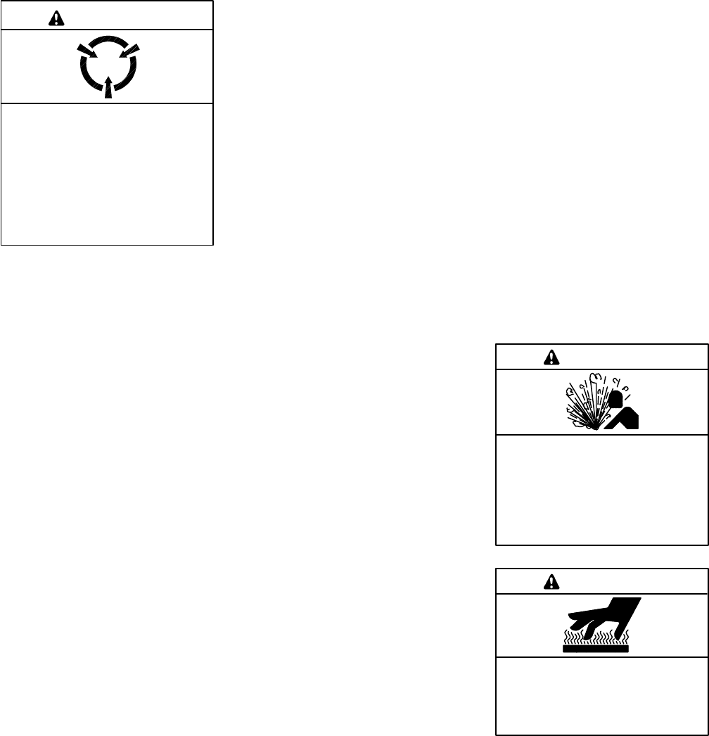
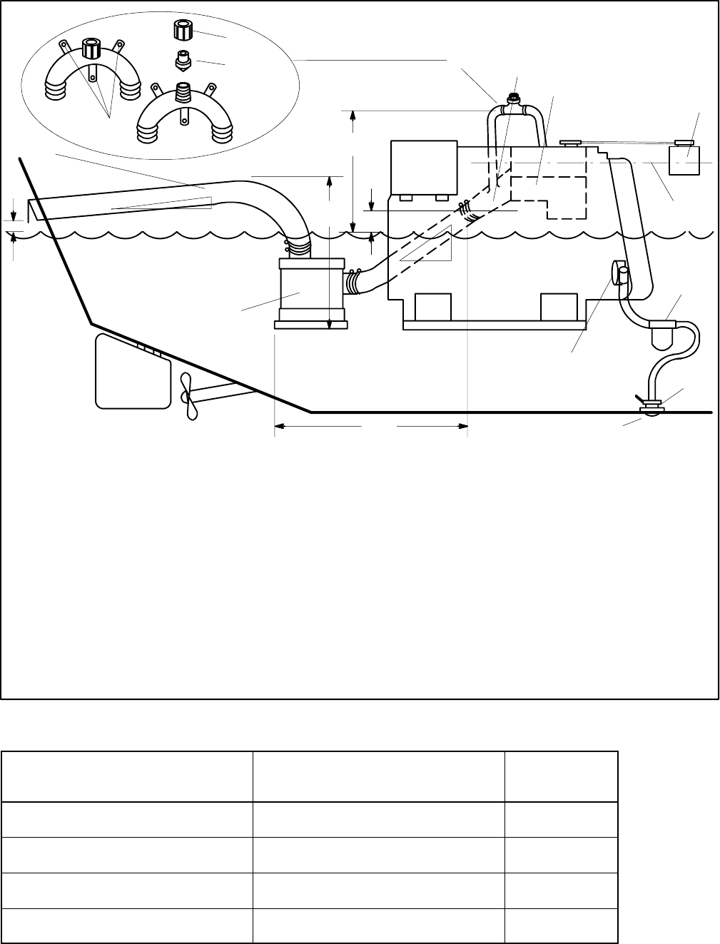
The safe and successful operation of a marine power
system depends primarily on the installation. See
Figure 1-1. Use this manual as a guide to install the
marine generator set. For operating instructions, refer
to the operation manual.
Marine generator set installations must comply with all
applicable regulations and standards.
Use the specification sheets as a guide in planning your
installation. Use current dimension drawings and wiring
diagrams.
KOHLER
12
3
4
5
6
7
8
9
10
11
12
13
14
15
16
17
585711
1. Exhaust mixer elbow (exhaust/water outlet) (not shown)
2. Heat exchanger (not shown)
3. Coolant recovery tank (located on the unit on some models)
4. Seawater strainer *
5. Seawater pump (seawater inlet)
6. Seawater line *
7. Seacock *
8. Craft stringers
9. Fuel feed pump (fuel inlet) *
10. Fuel return line *
11. Hose clamps
12. Fuel supply line *
13. Mounting tray (mounting skid on 33--150 kW models)
14. Battery/battery storage box
15. Battery cables
16. Exhaust hose or exhaust line *
17. Electrical leads (AC output leads/remote start panel leads)
* Indicated components must conform to USCG regulations.
Figure 1-1 Typical Generator Set Location and Mounting
Note: See text for complete explanation of installation
requirements.
Note: Use two hose clamps on each end of all flexible
exhaust hose connections.
TP-6069 6/032 Section 1 Introduction
Notes

TP-6069 6/03 3Section 2 Location and Mounting
Section 2 Location and Mounting
2.1 General Considerations
The key to installation is location. Before making final
plans for locating a generator set, consider the
following.
Installation Location Considerations
1. Choose a location that allows adequate space for
cooling and exhaust system installation, fuel
system installation, ventilation, and service access
to the generator set (engine and generator).
2. Use craft stringers or other available structural
members capable of supporting the generator set’s
weight.
3. Seal the generator set compartment from the cabin
to prevent exhaust gases and fuel vapors from
entering the cabin.
See the current generator set specification sheet or
Section 7 of this manual for generator set dimensions
and weights. See Figure 1-1 for a typical installation.
m:is:101:001
2.2 Location
Locate the generator set to allow easy service access to
the generator set’s engine, controller, cooling, and fuel
system components. The engine compartment is often
the ideal location for the generator set if the propulsion
engine(s) does not obstruct access to the generator set
and controller.
Marine Generator Set Installations in
European Union Member Countries
This generator set is specifically intended and approved
for installation below the deck in the engine
compartment. Installation above the deck and/or
outdoors would constitute a violation of European Union
Directive 2000/14/EC noise emission standard.
Allow clearance for vibration and cooling during
operation. Allow a minimum of 38 mm (1.5 in.)
clearance on all sides (top, front, rear, and sides) of a
generator set without an optional sound shield. Refer to
the instruction sheet for minimum clearances for
sound-shielded units. Also, allow space for the power
takeoff (PTO) option, if equipped.
Diesel generator sets are not ignition-protected. USCG
Regulation 183.410 requires ignition-protected devices
only in gasoline/gaseous-fueled environments.
2.3 Mounting
Mount the generator set as high as possible to avoid
contact with bilge splash and lower-lying vapors and to
allow for downward pitch of the exhaust line toward the
exhaust outlet.
Craft stringers generally provide the best generator set
support. Ensure that the structural members can
support the generator set’s weight and withstand its
vibration.
The generator set includes vibration mounts and a
mounting tray or skid. If desired, install additional
vibration isolating pads underneath the generator set’s
base.
Use the four mounting holes in the mounting tray to
mount the generator set securely to the craft.
For angular operating limits, consult the operation
manual.
TP-6069 6/034 Section 2 Location and Mounting
Notes
TP-6069 6/03 5Section 3 Cooling System
Section 3 Cooling System
3.1 Ventilation
Engine combustion, generator cooling, and expulsion of
flammable and lethal fumes require ventilation. Provide
ventilation compliant with USCG Regulations governing
sizing of vents and other considerations.
As a rule, size each inlet- and outlet-vent area to a
minimum of 13 sq. cm/30.5 cm (2 sq. in. per ft.) of the
craft’s beam. Should this rule conflict with USCG
Regulations, follow USCG Regulations. For applications
with screened inlets, double the size (4 sq. in. per ft.) of
the hull/deck openings. Extend the vent ducts to bilges to
expel heavier-than-air fumes.
For generator sets mounted in the engine compartment,
increase the air flow to allow for the generator set’s
requirements. Install optional detection devices to
cause alarm, warning, or engine shutdown should
dangerous fumes accumulate in the compartment.
See the generator set specification sheet that shipped
with the generator set for air requirements. The air intake
silencer/cleaner provides combustion air to the engine.
Do not compromise the recommended minimum
clearance of 38 mm (1.5 in.) between a duct opening and
enclosure wall. The engine/generator performance will
decline if you compromise these guidelines. See
Figure 3-1 for allowable intake restriction.
Note: ISO 3046 derates apply. See Appendix C.
Model Allowable Intake Restriction
3.5EFOZ/4EOZ 200 mm H2O (1.96 kPa or less)
4--125EFOZ/5--150EOZ 635 mm H2O (6.23 kPa or less)
Figure 3-1 Combustion Air Intake Restriction
3.2 Cooling System Components
The marine generator set’s cooling system requires the
following components.
3.2.1 Intake Through-Hull Strainer
(Seacock Cover)
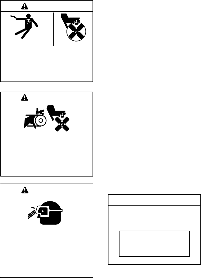
Install a screened-intake, through-hull strainer to
prevent entry of foreign objects. Use perforated,
slotted-hole, or unrestricted-hole design strainers. See
Figure 3-2 for examples of typical strainers. The inner
diameter of the strainer opening must be equal to or
greater than the inner diameter of the water-line hose to
the seawater pump.
1
2
3
4
51-789
1. Inside packing
2. Outside packing
3. Seacock cover
4. Direction of vessel movement
5. Typical intake through-hull strainers
Figure 3-2 Seacock Installation
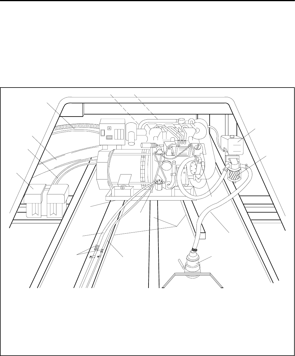
Do not align the strainer (in relation to the craft’s direction
of travel) with any other through-hull intakes. See
Figure 3-3. Flush mount the recommended through-hull
strainer. Install slotted-hole-design strainers with the
slots parallel to the direction of the vessel’s movement.
Note: Position the intakes in relation to the vessel’s
travel so neither is in the wake of the other.
1
2
4 3
1-789
1. Generator set intake
2. Main engine intake
3. Aft (rearward)
4. Fore (forward)
Figure 3-3 Intake Strainer
TP-6069 6/036 Section 3 Cooling System
Do not use a speed scoop or cup design intake
through-hull strainer because it can cause a ramming
effect and force water upward, past the seawater pump,
and into the engine cylinders when the vessel is moving
and the generator set is shut down.
Do not use hulls incorporating sea chests or other
designs that provide a positive pressure to the raw water
pump for the intake through-hull strainers. Positive
pressure forces water past the raw water pump and into
the engine. A sea chest is a concave molded-in-the-hull
chamber that aligns to the vessel’s direction of travel. A
sea chest configuration applies positive pressure similar
to a scoop-type through-hull strainer.
3.2.2 Seacock
Mount the seacock to the hull, assemble it to the intake,
and ensure that it is accessible for operation. Figure 3-2
shows a typical installation.
Avoid overcaulking the seacock. Excess caulk reduces
water flow and, in some cases, develops a barrier that
can force water upward, past the seawater pump, and
into the engine cylinders when the vessel is moving and
the generator set is shut down.
3.2.3 Seawater Strainer
Mount the seawater strainer to the seacock or
permanent structure at a point not higher than the
seawater pump. Ensure that the strainer is accessible
for service. See Figure 3-4 for a typical installation.
Some seawater strainers include a seacock and an
intake through-hull strainer.
Maximum seawater inlet pressure at the seawater pump
is 34.5 kPa (5 psi). Excessive pressure will cause water
ingestion.
1
2
3
1-789
1. Seawater pump
2. Seawater strainer
3. Seacock
Figure 3-4 Seawater Strainer
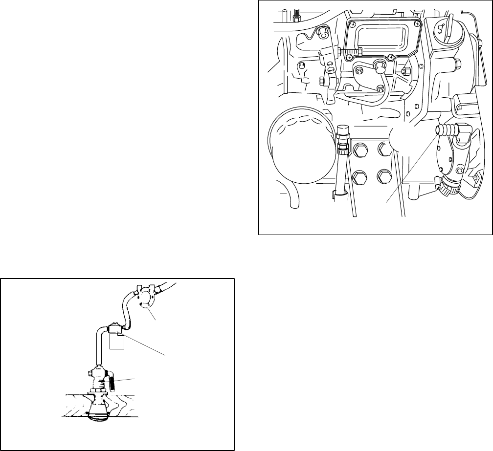
3.2.4 Water Lines
Water lines from the seacock to the engine-driven
seawater pump are usually constructed of flexible hose.
Connect a flexible section of hose to the seawater pump
to allow the generator set to vibrate during operation.
Support a nonflexible water line within 102 mm (4 in.) of
its connection to the flexible section.
Keep the seawater hose as straight and short as
possible. If the hose is too long, usually over 4.6 m
(15 ft.), water draw problems may occur. See Section 7
for the inlet water line hose size and the seawater
connection to the seawater pump inlet. Avoid running
the inlet pipe above the generator. See Figure 3-5 for
the seawater hose connection to the seawater pump
inlet.
1
TP-5586-6
1. Seawater pump inlet
Figure 3-5 Seawater Inlet Connection, Typical
3.2.5 Closed Heat Exchanger
(4--125EFOZ/5--150EOZ Models)
A closed heat exchanger is the best cooling method for
most applications. See Figure 3-6 or Figure 3-7 for a
typical installation. Provide space to access the
water-cooled exhaust manifold pressure cap.
3.2.6 Direct Water Cooled
(3.5EFOZ/4EOZ Models)
In a direct seawater cooling system, the impeller pump
circulates the seawater around the cylinder and through
the cylinder head. A thermostat controls the cooling water
circuit temperature. Consult Figure 3-8 and the engine
operation manual for the cooling water circuit diagrams.
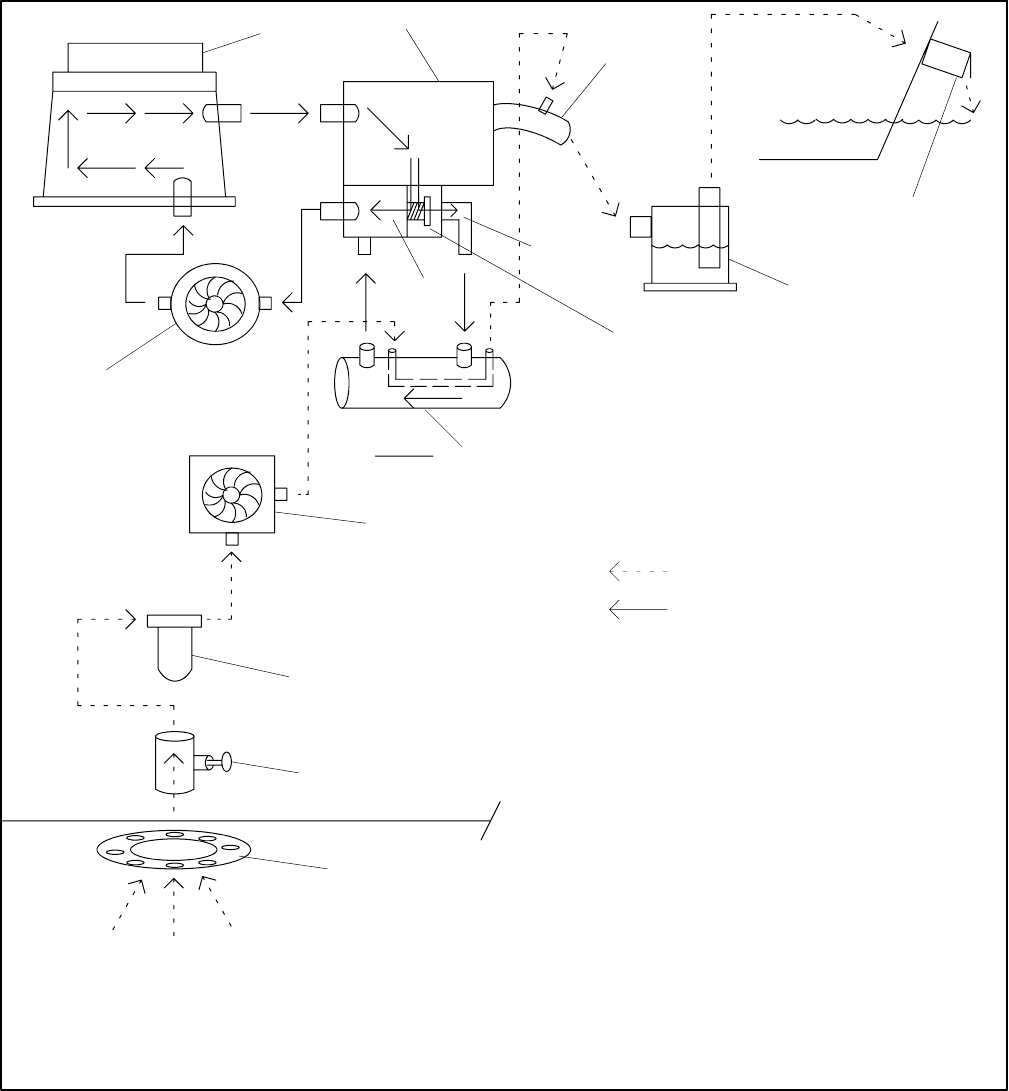
TP-6069 6/03 7Section 3 Cooling System
Seawater
Freshwater (Coolant/Antifreeze)
13
12
11
10
9
7
6
8
3
2
5
4
1
14
Arrow Description
Direction of Flow
TP-5586-6
1. Engine block
2. Exhaust manifold
3. Exhaust mixer elbow
4. Outlet flapper (exhaust/water discharge)
5. Silencer (customer supplied)
6. Thermostat open
7. Thermostat
8. Thermostat closed
9. Heat exchanger
10. Engine-driven seawater pump
11. Seawater strainer
12. Seacock
13. Intake strainer
14. Engine-driven water pump
Figure 3-6 Typical Closed/Heat Exchanger Cooling System (4/6.5/8.5/9/23/27EFOZ and 5/8/10/28/32EOZ
Models)
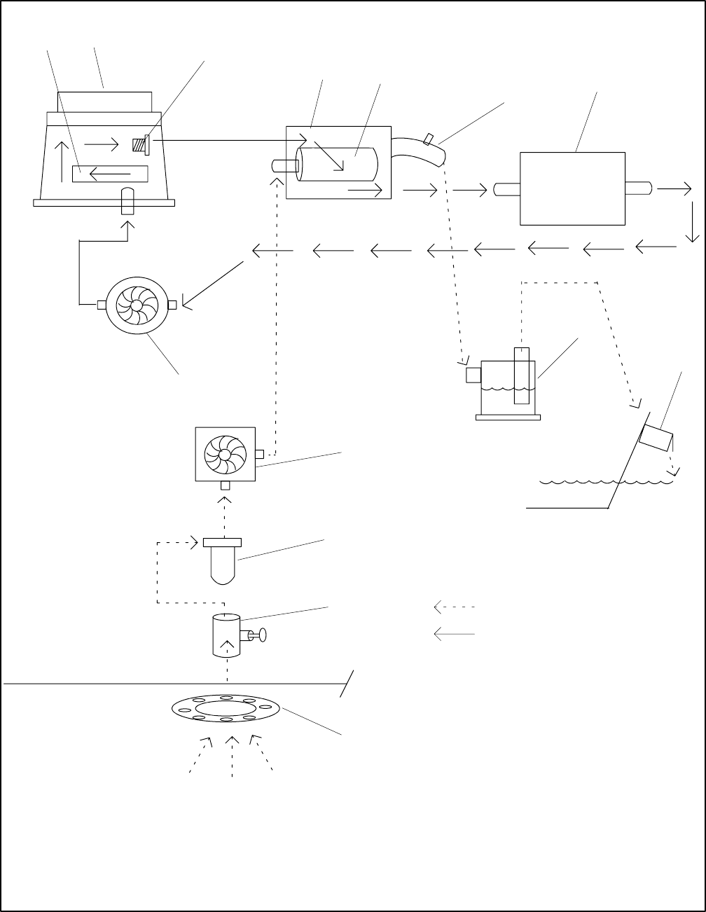
TP-6069 6/038 Section 3 Cooling System
Seawater
Freshwater (Coolant/Antifreeze)
TP-5592-6
12
3
45
6
7
8
9
10
11
12
13
14
1. Oil cooler
2. Engine block
3. Thermostat
4. Water-cooled manifold
5. Heat exchanger
6. Exhaust mixer elbow
7. Water-cooled turbocharger
8. Silencer (customer-supplied)
9. Exhaust outlet
10. Intake strainer
11. Seacock
12. Seawater strainer
13. Engine-driven seawater pump
14. Engine-driven water pump
Figure 3-7 Typical Closed/Heat Exchanger Cooling System (11--20EFOZ,13--24EOZ, 33--125EFOZ and
40--150EOZ Models)
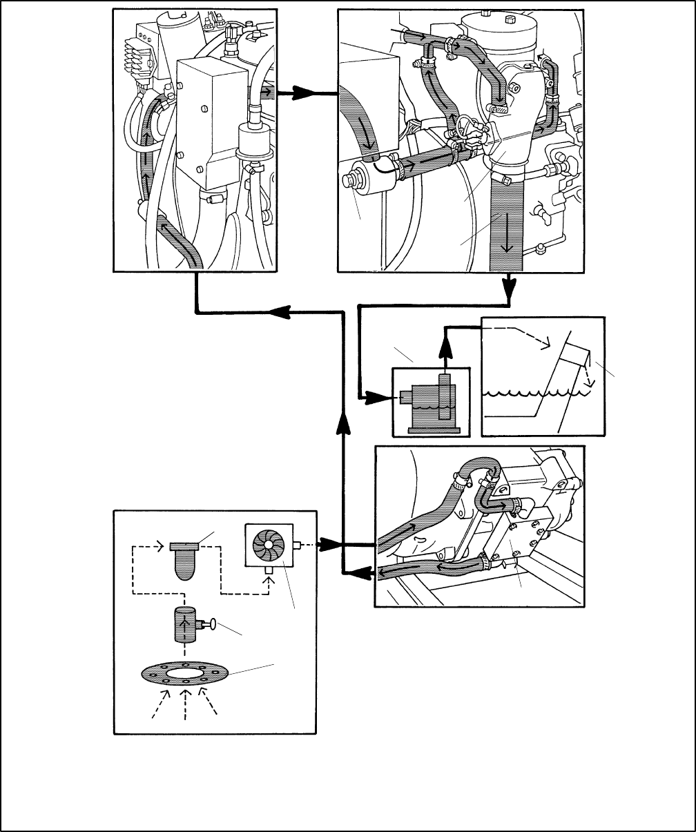
TP-6069 6/03 9Section 3 Cooling System
1
TP-6134-
1. Intake strainer
2. Seacock
3. Seawater strainer
4. Engine-driven seawater pump
5. Oil exchanger
6. Zinc plug
7. Exhaust manifold elbow
8. Exhaust hose
9. Silencer (customer supplied)
10. Outlet flapper (exhaust/water discharge)
2
3
4
5
6
7
8
9
10
Figure 3-8 Direct Water-Cooled Cooling System (3.5EFOZ and 4EOZ Models)
TP-6069 6/0310 Section 3 Cooling System
Notes
TP-6069 6/03 11Section 4 Exhaust System
Section 4 Exhaust System
Carbon monoxide.
Can cause severe nausea,
fainting, or death.
The exhaust system must be leakproof
and routinely inspected.
WARNING
Carbon monoxide symptoms. Carbon monoxide can
cause severe nausea, fainting, or death. Carbon monoxide
is a poisonous gas present in exhaust gases. Carbon
monoxide poisoning symptoms include but are not limited to
the following:
DLight-headedness, dizziness
DPhysical fatigue, weakness in
joints and muscles
DSleepiness, mental fatigue,
inability to concentrate
or speak clearly, blurred vision
DStomachache, vomiting, nausea
If experiencing any of these symptoms and carbon monoxide
poisoning is possible, seek fresh air immediately and remain
active. Do not sit, lie down, or fall asleep. Alert others to the
possibility of carbon monoxide poisoning. Seek medical
attention if the condition of affected persons does not improve
within minutes of breathing fresh air.
Inspecting the exhaust system. Carbon monoxide can
cause severe nausea, fainting, or death. For the safety of
the craft’s occupants, install a carbon monoxide detector.
Consult the boat builder or dealer for approved detector
location and installation. Inspect the detector before each
generator set use. In addition to routine exhaust system
inspection, test the carbon monoxide detector per the
manufacturer’s instructions and keep the detector operational
at all times.
Operating the generator set. Carbon monoxide can cause
severe nausea, fainting, or death. Carbon monoxide is an
odorless, colorless, tasteless, nonirritating gas that can cause
death if inhaled for even a short time. Use the following
precautions when installing and operating the generator set.
Do not install the exhaust outlet where exhaust can be drawn
in through portholes, vents, or air conditioners. If the generator
set exhaust discharge outlet is near the waterline, water could
enter the exhaust discharge outlet and close or restrict the flow
of exhaust. Never operate the generator set without a
functioning carbon monoxide detector. Be especially careful if
operating the generator set when moored or anchored under
calm conditions because gases may accumulate. If operating
the generator set dockside, moor the craft so that the exhaust
discharges on the lee side (the side sheltered from the wind).
Always be aware of others, making sure your exhaust is
directed away from other boats and buildings. Avoid
overloading the craft.
4.1 Types
Kohlerrgenerator sets covered in this manual use
either wet or dry exhaust systems. Dry exhaust systems
are common in commercial applications. See the
engine manual for specifications.
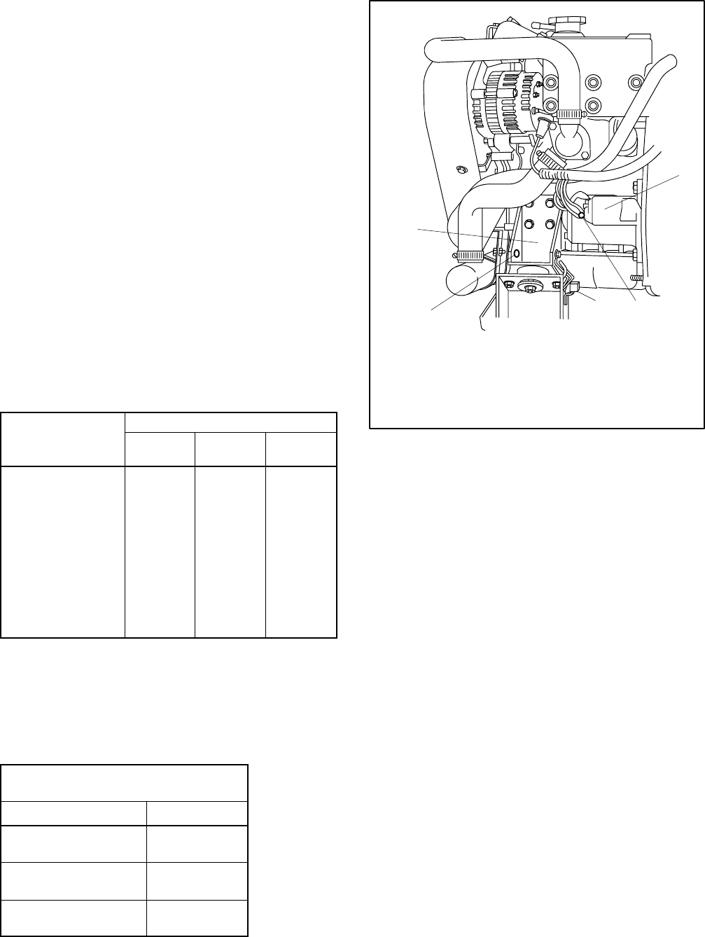
4.2 Exhaust Lines
Use water-cooled exhaust lines in all marine
installations. Keep the lines as short and straight as
possible. NFPA 302 Fire Protection Standard for
Pleasure and Commercial Motor Craft, Clause 4-3,
recommends using two corrosion-resistant hose
clamps with a minimum width of 13 mm (1/2 in.) on each
end of the flexible exhaust hose connections.
Kohler Co. requires a downward pitch of at least 13 mm
per 30.5 cm (1/2 in. per running foot). Use a flexible
exhaust hose that conforms to UL Standard 1129 for the
engine’s wet exhaust components between the mixer
elbow and the exhaust outlet.
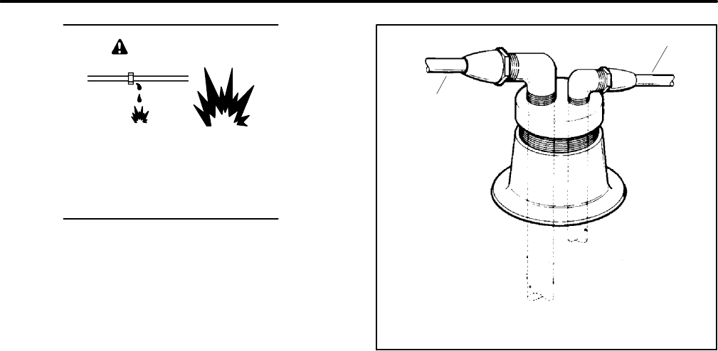
TP-6069 6/0312 Section 4 Exhaust System
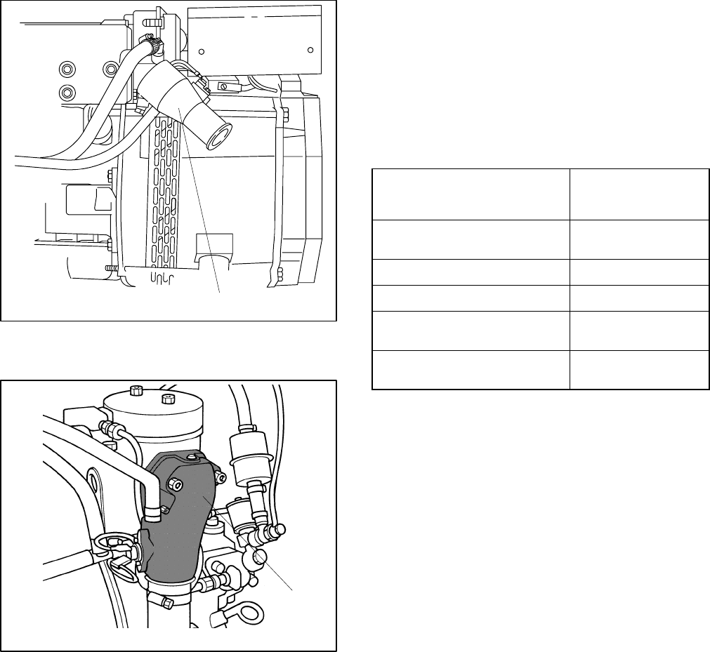
4.3 Exhaust System Location,
Mounting, and Installation
Mount the silencer independently to eliminate stress on
the exhaust system and the exhaust manifold/mixer
elbow. See Section 7 for the mixer elbow water line hose
size. See Figure 4-1 for the exhaust connection to the
mixer elbow. Provide an adequate hose length from the
exhaust mixer to the silencer to allow for generator set
movement.
1TP-5586-6
1. Water/exhaust outlet
Figure 4-1 Mixer Elbow/Exhaust Connection,
Typical
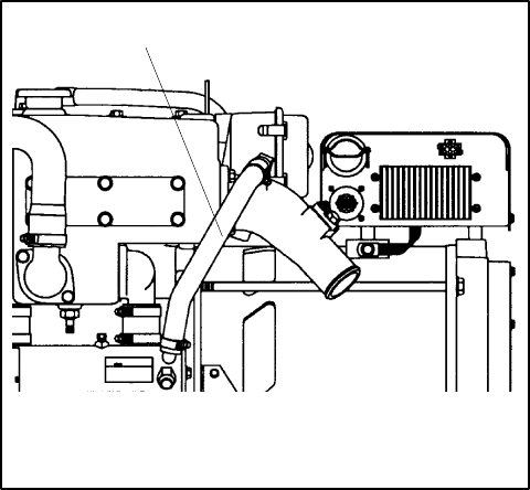
1
TP-6134-
1. Water/exhaust outlet
Figure 4-2 Mixer Elbow/Exhaust Connection,
3.5EFOZ/4EOZ Model Only
Locate the exhaust outlet at least 10 cm (4 in.) above the
waterline when the craft is loaded to maximum capacity.
Install an exhaust port with the flap at the exhaust
(transom) outlet to prevent water backup in following
seas or when moving astern (backward). A lift in the
exhaust piping before the piping exits the craft prevents
backwash. See Figure 4-4, item 1. Support the exhaust
lines to prevent the formation of water pockets.
Exhaust system installation guidelines for various
generator set locations follow. Information and
illustrations of stern- (rear) exhaust installations also
apply to side-exhaust installations. Where exhaust lines
require passage through bulkheads, use port (left)- or
starboard (right)- side exhaust outlets, also in
applications in which long exhaust lines to the transom
(rear) could cause excessive back pressure. See
Figure 4-3 for allowable back pressures. Should any
information regarding installation conflict with USCG
Regulations, follow USCG Regulations.
Model
Allowable Exhaust
Back Pressure,
≤kPa (mm H2O)
4/8.5/9/23/27EFOZ and
5/10/28/32EOZ 9.81 (1000)
6.5EFOZ and 8EOZ 11.77 (1200)
11/16/17.5EFOZ and 13/20EOZ 6.37 (650)
3.5/11.5/13/19/20EFOZ and
4/14/15.5/23/24EOZ 4.90 (500)
33/40/55/70/80/100/125EFOZ
and 40/50/65/80/99/125/150EOZ 7.47 (762)
Figure 4-3 Allowable Exhaust Back Pressures
4.3.1 Above-Waterline Installation
Install a customer-supplied silencer with the silencer’s
outlet at a maximum of 3 m (10 horizontal ft.) from the
center of the engine’s exhaust outlet. See Figure 4-4.
Mount a typical silencer with the inlet and outlet
horizontal and with the drain plug down. Use an exhaust
hose pitch of at least 13 mm per 30.5 cm (0.5 in. per
running foot). Some silencers require two support
brackets or hanger straps for installation to stringers or
other suitable structure. Follow the instructions
provided with the silencer. Install any lift (see
Figure 4-4, item 1) in the exhaust line below the engine
exhaust manifold outlet.
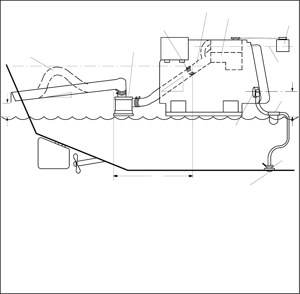
TP-6069 6/03 13Section 4 Exhaust System
Waterline
1
2
4
5
6
7
8
9
10
11
12
13
14
15
16
3
TP-5856-4
1. Slight lift improves silencing and prevents water backwash
into the silencer (keep below the level of the exhaust
manifold outlet)
2. Silencer (customer-supplied)
3. Exhaust manifold outlet
4. Exhaust mixer elbow
5. Heat exchanger (locations vary by model)
6. Coolant recovery tank (located on the unit on some models)
7. Locate the coolant recovery tank at the same height as the
heat exchanger
8. Maximum seawater pump lift of 1 m (3 ft.)
9. Seawater strainer
10. Seacock
11. Intake strainer
12. Engine-driven seawater pump
13. Minimum exhaust hose pitch of 1.3 cm per 30.5 cm (0.5 in.
per ft.)
14. Maximum distance between silencer and exhaust mixer
elbow of 3 m (10 ft.)
15. Minimum exhaust hose pitch of 1.3 cm per 30.5 cm (0.5 in.
per ft.)
16. Minimum exhaust outlet distance above waterline of 10 cm
(4 in.). Note: Vessel fully loaded.
Note: Data applies to both rear- and side-exhaust installations.
Note: Use two hose clamps on each end of all flexible exhaust
hose connections.
Note: Read the text for complete explanation of dimensions
and other installation considerations.
Figure 4-4 Typical Above-Waterline Installation
TP-6069 6/0314 Section 4 Exhaust System
4.3.2 Mid/Below-Waterline Installation
Follow USCG Regulations for installing an antisiphon
provision to prevent raw water entry into the engine.
Use the siphon break if the exhaust manifold outlet is
located less than 23 cm (9 in.) above the waterline when
the craft is loaded to maximum capacity. Install the
siphon break at least 31 cm (1 ft.) above the waterline
using the instructions provided with the siphon break kit.
Note: An improperly installed siphon break will cause
engine damage and may void the warranty.
Install the siphon break above the highest point in the
exhaust line between the heat exchanger and the
exhaust mixer. See Figure 4-5 for the siphon break
connection. Support the siphon break and hoses to
maintain their position and function. Allow a slight offset
to clear the stringers or other permanent structures.
Protect the siphon break air inlet from dirt and debris.
Note: To prevent water leakage on the generator set, do
not mount the siphon break directly over the
generator set.
1
TP-5586-6
1. Cut hose and connect siphon break and hardware
Figure 4-5 Siphon Break Connection (4EFOZ/5EOZ
model shown)
Mount a typical silencer’s base no more than 1.2 m (4 ft.)
below the highest point in the exhaust line. Attach a
separate wood mounting base to the hull stringers or
other suitable structures. Use the silencer
manufacturer’s recommendation for securing the
silencer to the hull. Mount the silencer with the outlet not
more than 3 m (10 horizontal ft.) from the engine’s
exhaust manifold outlet. Use a USCG-type certified
marine exhaust hose.
TP-6069 6/03 15Section 4 Exhaust System
Waterline
7
14
13
12
15
10
9
8
18
11
19
6
17
4
5
20 16
1
2
3
21
TP-5856-4
1. Mounting base
2. Retaining cap
3. Reed valve assembly
4. Maximum silencer vertical lift of 1.2 m (4 ft.)
5. Exhaust mixer elbow distance above waterline; if less than
23 cm (9 in.), a siphon break is required
6. Minimum siphon break distance above waterline of 30.5 cm
(1 ft.)
7. Siphon break
8. Exhaust mixer elbow
9. Heat exchanger (locations vary by model)
10. Coolant recovery tank (located on the unit on some models)
11. Indicates the coolant recovery tank is at the same height as the
heat exchanger
12. Seawater strainer
13. Seacock
14. Intake strainer
15. Engine-driven seawater pump
16. Minimum exhaust hose pitch of 1.3 cm per 30.5 cm (0.5 in. per ft.)
17. Maximum distance between silencer and exhaust mixer elbow
of 3 m (10 ft.)
18. Silencer (customer-supplied)
19. Minimum exhaust hose pitch of 1.3 cm per 30.5 cm
(0.5 in. per ft.)
20. Minimum exhaust outlet distance above waterline of 10 cm
(4 in.)
21. Exhaust hose (see Figure 4-7 for hose sizes)
Note: Read the text for complete explanation of dimensions and
other installation considerations.
Note: Use two hose clamps on each end of all flexible exhaust
hose connections.
Note: Data applies to both rear- and side-exhaust installations.
Figure 4-6 Typical Mid and Below Waterline Installation
Models without Sound Shield Models with Sound Shield
Exhaust Hose
Diameter
mm (in.)
3.5/4/6.5/8.5/9EFOZ
4/5/8/10EOZ
4/6.5/8.5/9/11/11.5/13/16/17.5/19/20EFOZ
5/8/10/13/14/15.5/20/23/24EOZ 51 (2.0)
11/11.5/13/16/17.5/19/20/23/27EFOZ
13/14/15.5/20/23/24/28/32EOZ
27EFOZ
32EOZ 76 (3.0)
33EFOZ
40EOZ
33EFOZ
40EOZ 89 (3.5)
40/55/70/80/100/125EFOZ
50/65/80/99/125/150EOZ
40/55/70/80/100/125EFOZ
50/65/80/99/125/150EOZ 102 (4.0)
Figure 4-7 Exhaust Hose Sizes
TP-6069 6/0316 Section 4 Exhaust System
Notes
TP-6069 6/03 17Section 5 Fuel System
Section 5 Fuel System
Explosive fuel vapors.
Can cause severe injury or death.
Use extreme care when handling, storing,
and using fuels.
WARNING
Installing the fuel system. Explosive fuel vapors can
cause severe injury or death. Fuel leakage can cause an
explosion. Do not modify the tank or the propulsion engine fuel
system. Equip the craft with a tank that allows one of the two
pickup arrangements described in the installation section. The
tank and installation must conform to USCG Regulations.
Note: Fuel system installations must conform to USCG
Regulations.
5.1 Fuel Tank
Most marine generator sets draw fuel from the same fuel
tank as the craft’s propulsion engine(s). If the tank’s fuel
pickup opening allows a multiple dip tube, use a multiple
dip tube arrangement. See Figure 5-1. The multiple dip
tube arrangement incorporates a shorter dip tube for the
generator set and a longer dip tube for the propulsion
engine. With this arrangement, the generator set runs
out of fuel before the propulsion engine during a low fuel
supply situation. Equip the fuel system with a fuel/water
separator to remove any accumulated dirt and water.
2
1-788
1
1. Fuel line to propulsion engine
2. Fuel line to generator set
Figure 5-1 Multiple Dip Tube Arrangement
m:is:102:001

TP-6069 6/0318 Section 5 Fuel System
5.2 Fuel Lines
Locate the fuel return line as far as practical from the fuel
pickup to allow the tank fuel to cool the return fuel before
delivery back to the fuel injectors. Incoming fuel cools
the injectors to achieve maximum engine efficiency.
Note: Do not tee into the main propulsion engine’s fuel
line.
Under no circumstances should the propulsion engine
and generator set share pickup or return lines (through a
tee arrangement) that would allow the larger engine to
starve fuel from the smaller engine. It is possible that the
operation of either engine could completely drain the
fuel line of the other engine and make starting difficult.
Use a flexible hose section to connect the metallic line
from the fuel tank to the engine’s fuel pump inlet
connection point. Also, use a flexible hose section to
connect the metallic line from the fuel tank to the fuel
return connection point. The flexible section allows the
generator set to vibrate during operation.
Model
Fuel Line
ID Size
mm (in.)
3.5EFOZ and 4EOZ 6.4 (1/4)
4--125EFOZ and 5--150EOZ 9.7 (3/8)
Figure 5-2 Fuel Line ID Size
See Figure 5-2 for the ID size of the customer-supplied
fuel line that connects to the fuel pump and fuel return.
Route the fuel lines from the fuel tank in a gradual incline
to the engine—do not exceed the height of the generator
set and do not route fuel lines above the generator set.
Comply with USCG Regulation 46CFR182.20
regarding fuel lines and supports.
See Section 7 for fuel feed pump inlet connection and
fuel return line connection.
5.3 Fuel Filters
Conform to USCG Regulations regarding inline fuel
filters or strainers.
5.4 Fuel Pump Lift
See Figure 5-3 for fuel pump lift capabilities.
Model
Fuel
Pump
Lift
m (ft.)
3.5/4/6.5/8.5/9/11/11.5/13/16/17.5/19/20/23/
27EFOZ and
4/5/8/10/13/14/15.5/20/23/24/28/32EOZ
1.2 (4)
33/40/55/70/80/100/125EFOZ
and 40/50/65/80/99/125/150EOZ 0.9 (3)
Figure 5-3 Fuel Pump Lift
5.5 Fuel Consumption
Consult the current generator set specification sheets
for generator set fuel consumption rates.
TP-6069 6/03 19Section 6 Electrical System
Section 6 Electrical System
Hazardous voltage.
Can cause severe injury or death.
Operate the generator set only when
all guards and electrical enclosures
areinplace.
Moving rotor.
WARNING
Electrical backfeed to the utility. Hazardous backfeed
voltage can cause severe injury or death. Connect the
generator set to the building/marina electrical system only
through an approved device and after the building/marina
main switch is opened. Backfeed connections can cause
severe injury or death to utility personnel working on power
lines and/or personnel near the work area. Some states and
localities prohibit unauthorized connection to the utility
electrical system. Install a ship-to-shore transfer switch to
prevent interconnection of the generator set power and shore
power.
1
2
3
4
5
6
585771
1. Line side
2. AC circuit breaker
3. Load side
4. L1/L2 phase (black) leads
5. GRD ground (green) lead
6. L0 neutral (white) lead
Figure 6-1 AC Voltage Connections in Controller
Box (5--32EOZ Models, Typical)
6.1 AC Voltage Connections
Make AC connections to the generator set inside the
controller box (4--27EFOZ and 5--32EOZ models) or
inside the junction box (33--125EFOZ and 40--150EOZ
models). Typically, the generator set connects to a
ship-to-shore transfer switch that allows the use of
shore/utility power when docked or generator set power
when docked or at sea. The wiring then connects to a
main circuit breaker box (panel board) that distributes
branch circuits throughout the craft. See Figure 6-1 for
AC voltage connections to the generator set. See
Section 8 for reconnection of the generator set.
6.2 Circuit Protection
The AC circuit breakers (optional) protect the wiring
from the AC circuit breakers to the vessel’s distribution
panel. AC circuit breakers trip when they detect a fault in
the output circuit.
After correcting the fault, reset the AC circuit breaker(s)
by placing them in the ON position. Restart the unit. Do
not start the unit under load. See Figure 6-2 or
Figure 6-3 for AC circuit breaker ratings. The unit’s
voltage configuration determines the circuit breaker
selection.
Note: Circuit breaker ampere rating and availability are
subject to change.
6.2.1 Circuit Breaker Considerations
Mounting location. Mount the circuit breakers in the
generator set’s controller (4--27EFOZ and 5--32EOZ
models) or the generator set’s junction box
(33--125EFOZ and 40--150EOZ models). See
Section 6.2.2 or Section 6.2.3.
Note: 3.5EFOZ and 4EOZ models already have circuit
breakers installed.
Sizing. Use the generator set voltage/frequency
configuration to determine the circuit breaker
amperage. If the generator set voltage configuration
changes, change the circuit breaker to provide optimum
protection.
For circuit breaker application and selection
information, contact an authorized distributor/dealer.
Have a qualified electrician or technician install circuit
breakers and reconnect the generator set. Comply with
all governing standards and codes.
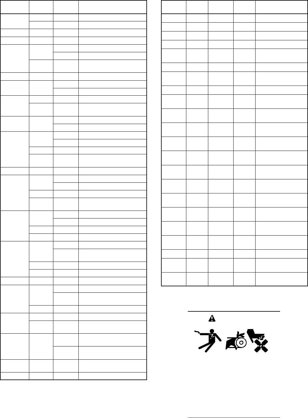
TP-6069 6/0320 Section 6 Electrical System
Amps
Max.
Voltage
Number
of Poles Model(s)
2
0
250 1 4EFOZ
2
0
600 3 8.5/11.5EFOZ, 14EOZ
22 250 2 4EFOZ, 5EOZ
25 250 2 5EOZ
2
5
0
16.5EFOZ
3
0
2
5
0
26.5EFOZ
3
0
600 3 11.5/17.5/20EFOZ,
14/20/24EOZ—3 phase
33 250 2 8EOZ
3
5
2
5
0
14EFOZ
3
5
2
5
0
28EOZ
250 1 5EOZ
40 600 3 11.5EFOZ,
14/20/24EOZ—3 phase
4
2
2
5
0
19EFOZ
4
2
2
5
0
29EFOZ, 8/10EOZ
2
4
0
111/13EFOZ
2
4
0
211/11.5/17.5EFOZ
50 250 2 9EFOZ, 10EOZ
480 3 20/23/27EFOZ,
20/28/32EOZ—3 phase
55 250 1 5EOZ
2
4
0
113EFOZ
2
4
0
211/13EFOZ, 13/14EOZ
60 250 1 6.5EFOZ
600 3 17.5/20EFOZ,
20/24/28/32EOZ—3 phase
2
4
0
116EFOZ
7
0
2
4
0
213/20EFOZ, 15.5EOZ
7
0
250 1 6.5EFOZ, 8EOZ
600 3 20/24EOZ—3 phase
116/19EFOZ
80
240 216EFOZ, 20EOZ—1 phase,
20/24EOZ—3 phase
8
0
250 1 8EOZ
480 3 23EFOZ—3 phase
85 250 1 9EFOZ, 10EOZ
119EFOZ
90 240 219EFOZ—1 phase
20/23EOZ
480 3 27EFOZ—3 phase
240 2 23EOZ
100 480 3 23/27EFOZ,
28/32EOZ—3 phase
1
2
5
6
0
0
223/27EFOZ, 28EOZ—
1 phase, 27EFOZ—3 phase
1
2
5
6
0
0
323/27EFOZ,
28/32EOZ—3 phase
150 600 2 28/32EOZ—1 phase,
32EOZ— 3 phase
175 600 2 32EOZ—1 phase
Figure 6-2 AC Circuit Breaker Ratings (4--27EFOZ
and 5--32EOZ Models), Listed By Amps
Amps
Max.
Voltage
Number
of Poles Type Model(s)
60 600 3 UL/IEC 33EFOZ, 40EOZ
70 600 3 UL/IEC 40EFOZ, 40EOZ
80 480 3 UL/IEC 40EFOZ, 50EOZ
100 480 3 UL/IEC 55EFOZ, 50/65EOZ
100--125 600 3 IEC 33/55EFOZ,
40/65EOZ
100--125 600 3 IEC 70EFOZ, 80EOZ
125 600 3 UL 33/55EFOZ,
40/65EOZ
125 600 3 UL 70EFOZ, 80EOZ
128--160 600 3 IEC 33/40EFOZ,
40/50EOZ
128--160 600 3 IEC 70/80EFOZ,
80/99EOZ
150 600 3 UL 33/40EFOZ,
40/50EOZ
150 600 3 UL 70/80EFOZ,
80/99EOZ
160--400 600 3 UL 70/80/100EFOZ,
80/99/125/150EOZ
160--400 600 3 IEC 70/80/100/125EFOZ,
80/99/125/150EOZ
200 600 3 UL 40/55EFOZ,
50/65EOZ
200 600 3 UL 100EFOZ,
99/125EOZ
200--250 600 3 IEC 40/55EFOZ,
50/65EOZ
200--250 600 3 IEC 70/100/125EFOZ,
80/125/150EOZ
240--600 600 3 UL 125EFOZ,
125/150EOZ
250 600 3 UL 55EFOZ, 65EOZ
250 600 3 UL 70/125EFOZ,
80/125/150EOZ
250--630 600 3 IEC 125EFOZ,
125/150EOZ
Figure 6-3 AC Circuit Breaker Ratings (33--150 kW
Models), Listed By Amps
Accidental starting.
Can cause severe injury or death.
Disconnect the battery cables before
working on the generator set.
Remove the negative (--) lead first
when disconnecting the battery.
Reconnect the negative (--) lead last
when reconnecting the battery.
WARNING
TP-6069 6/03 21Section 6 Electrical System
Disabling the generator set. Accidental starting can
cause severe injury or death. Before working on the
generator set or equipment connected to the set, disable the
generator set as follows: (1) Place the generator set start/stop
switch in the STOP position. (2) Disconnect the power to the
battery charger, if equipped. (3) Remove the battery cables,
negative (--) lead first. Reconnect the negative (--) lead last
when reconnecting the battery. Follow these precautions to
prevent the starting of the generator set by the remote
start/stop switch.
Hazardous voltage.
Can cause severe injury or death.
Operate the generator set only when
all guards and electrical enclosures
areinplace.
Moving rotor.
WARNING
Grounding electrical equipment. Hazardous voltage can
cause severe injury or death. Electrocution is possible
whenever electricity is present. Open the main circuit
breakers of all power sources before servicing the equipment.
Configure the installation to electrically ground the generator
set, transfer switch, and related equipment and electrical
circuits to comply with applicable codes and standards. Never
contact electrical leads or appliances when standing in water
or on wet ground because these conditions increase the risk of
electrocution.
Short circuits. Hazardous voltage/current can cause
severe injury or death. Short circuits can cause bodily injury
and/or equipment damage.Do not contact electrical
connections with tools or jewelry while making adjustments or
repairs. Remove all jewelry before servicing the equipment.
Electrical backfeed to the utility. Hazardous backfeed
voltage can cause severe injury or death. Connect the
generator set to the building/marina electrical system only
through an approved device and after the building/marina
main switch is opened. Backfeed connections can cause
severe injury or death to utility personnel working on power
lines and/or personnel near the work area. Some states and
localities prohibit unauthorized connection to the utility
electrical system. Install a ship-to-shore transfer switch to
prevent interconnection of the generator set power and shore
power.
6.2.2 Circuit Breaker Installation
(4--27EFOZ and 5--32EOZ Models)
1. Place the generator set start/stop switch in the
STOP position.
2. Disconnect the generator set engine starting
battery, negative (--) lead first.
3. Remove the controller cover screws and remove
the access cover.
4. Remove the screws and nuts to remove the circuit
breaker cover plate. Save the mounting hardware.
5. Install the circuit breaker from the inside of the
cutout panel and mount it using existing screws
removed in step 4. Position the circuit breaker with
the ON in the normal upright position or to the left
side. Cover the cutout opening, if applicable, with
the circuit breaker cover plate. Use existing screws
to mount the cover plate.
6. See Section 8 for voltage reconnection.
Note: Kohlerrmarine diesel generator sets are
fully frequency adjustable and voltage
reconnectable. To determine reconnection
options, check the model’s specification
sheet.
7. Install insulation boots over stator lead terminals if
the kit includes insulation boots.
Note: See Section 8 for wiring instructions.
8. Make the recommended connections for the
following four reconnection systems using circuit
breakers:
Two-pole circuit breaker with a single-voltage
system (example: 120-volt, 3-wire). Attach
stator leads marked 2 and 4 to the side of the circuit
breaker marked LINE. Install the jumper lead
across the LINE side of circuit breaker terminals
(see Section 8). Attach stator leads 1 and 3 to L0.
Single-pole circuit breaker with a 120-volt,
2-wire, single-voltage system. Attach stator
leads marked 2 and 4 to the side of the circuit
breaker marked LINE (see Section 8). Attach stator
leads 1 and 3 to L0.
Two-pole circuit breaker with a dual-voltage
system (example: 120/240-volt, 3-wire). Attach
stator leads marked 1 and 4 to the side of the circuit
breaker marked LINE. Do not use a jumper lead
(see Section 8). Attach stator leads 2 and 3 to L0.
Single-pole circuit breaker with a 240-volt,
2-wire, single-voltage system. Attach the stator
lead marked 2 to the side of the circuit breaker
marked LINE (see Section 8). Bolt together leads 1
and 4 and tape to insulate from ground. Attach the
stator lead marked 3 to L0.
9. Connect the stator lead(s) used for neutral
connection to the L0 stud. See the illustrations in
Section 8.
TP-6069 6/0322 Section 6 Electrical System
10. Connect the side of the circuit breaker marked
LOAD to the ship-to-shore switch or craft wiring.
Attach insulation boots to the black leads if the kit
includes insulation boots. With a single-pole circuit
breaker use one black lead (L1). With a two-pole
circuit breaker use two black leads, L1 and L2.
Connect the neutral (white) lead to the L0 stud.
Connect the equipment ground (green) lead to
GRD stud.
Note: Wire material. Use stranded copper for all
wiring. Use wire gauges and insulation,
conductor temperature ratings, sheath
stripping, conductor support and protection,
conductor terminals and splices, and
overcurrent protection (circuit breakers,
fuses) that conform to standards and codes.
Note: Follow USCG Regulations CFR33, Part 183
(Pleasurecraft) and CFR46 (Commercial
Craft) for marine applications.
Note: Wire protection. Use rubber grommets
and cable ties as necessary to protect and
secure wiring from sharp objects, the
exhaust system, and any moving parts.
11. Replace the controller cover or circuit breaker box
access panel.
12. Reconnect the generator set engine starting
battery, negative (--) lead last.
13. Make voltage or frequency adjustments according
to Section 8.
Note: Voltage/frequency adjustable. Some
four-lead generator sets are not
voltage/frequency adjustable. To determine
adjustment possibilities, check the model’s
specification sheet or service manual. If you
are reconnecting the generator set from a
single-voltage to a dual-voltage
configuration (example: from 120-volt to
120/240-volt) or a dual voltage to a single
voltage (example: from 120/240-volt to
120-volt) with the same primary voltage, do
not adjust the voltage/frequency
adjustment. Adjust the voltage/frequency
for frequency changes or setting changes of
the primary voltage (example: from 120-volt
to 100-volt). Refer to the model’s
specification sheet for reconnection
capability.
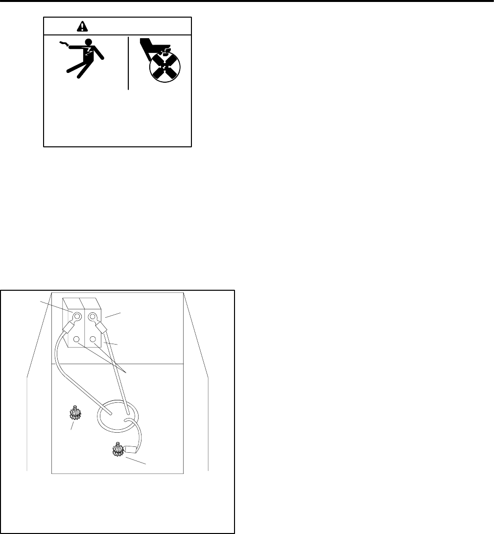
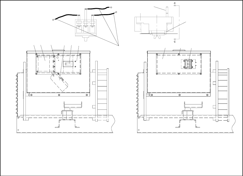
6.2.3 Circuit Breaker Installation
(33--125EFOZ and 40--150EOZ
Models)
1. Place the generator set master switch in the OFF
position.
2. Disconnect the generator set engine starting
battery, negative (--) lead first.
3. Remove the six screws from the right side junction
box panel and remove the panel.
4. Install the circuit breaker on the new panel with the
screws and washers. Position the ON side of the
circuit breaker toward the rear of the junction box.
See Figure 6-4.
5. Attach stator leads L1, L2, and L3 to the extension
leads (if supplied) or to the line side of the circuit
breaker. See Figure 8-5.
Note: Insulate leads with electrical tape after
connecting extension leads to stator leads.
6. Connect the neutral connection stator leads to the
L0 stud.
Note: Verify that terminal positions and previously
made line lead connections allow room for
load connections to load studs.
7. Connect the load side of the circuit breaker to
customer-supplied craft wiring. Connect the
neutral lead to the L0 stud. See Figure 8-5.
8. Attach the new panel to the junction box using the
original six screws. See Figure 6-4.
9. Check that the generator set master switch is in the
OFF position. Reconnect the generator set engine
starting battery, negative (--) lead last.
TP-6069 6/03 23Section 6 Electrical System
12 3 4 56
9
156
ASSEMBLY VIEW A ASSEMBLY VIEW B
DX-250000-B
7
8
ASSEMBLY VIEW C-C
1. Existing mounting hardware
2. Load lead access panel
3. Screw
4. Hang tag
5. Circuit breaker
6. Circuit breaker panel
7. Extension leads, if equipped
8. Rear connection used on 125-250 amp circuit breaker
9. Spacer used on 125-250 amp circuit breaker
Figure 6-4 Circuit Breaker Mounting
6.3 Installation In Steel or
Aluminum Vessels
Installation of a generator set in a vessel constructed of
a material capable of conducting current (e.g., steel or
aluminum) is subject to considerations not normally
encountered in fiberglass or wood vessels. These
differences include equipment grounding, grounding of
neutral conductors, ground-fault protection, and
isolation of galvanic currents.
The scope of these topics is too extensive to be fully
discussed here. Consult your local marine authority for
more information.
Before installing the generator set, check the available
wiring diagrams in the operation manual to become
familiar with the electrical system.
6.4 Installation Regulations
The U.S. Coast Guard governs generator set
installation in U.S. pleasurecraft and commercial
vessels. Refer to the applicable regulations below:
U.S. Pleasurecraft Installation
Regulations
Title 33CFR, Chapter I, U.S. Coast Guard, Part 183
1. Subpart I—Electrical Equipment
2. Subpart J—Fuel Systems
U.S. Commercial Vessel Installation
Regulations
Title 46CFR, Chapter I, U.S. Coast Guard
1. Part 111—Electrical Systems
2. Part 182—Machinery Installation
m:sc:001:001
TP-6069 6/0324 Section 6 Electrical System
6.5 Battery
Batteries and their installation must conform to USCG
Regulations 183.420 (a) through (g). Provide generator
sets with batteries separate from the propulsion
engine’s whenever possible. The starting/charging
systems of both the generator set and the engine must
have a common negative (--) ground.
USCG Regulation 183.415, Grounding, requires
connection of a common conductor to each grounded
cranking-motor circuit. Size the conductor to match the
larger of the engine’s two battery cables. Figure 6-5 lists
cable sizes for generator set battery connections at
various ambient temperatures. Connecting a common
conductor to each grounded cranking motor circuit
prevents the starting motor current from using
alternative electrical paths should the cranking motor
ground circuit be restricted or open because of oxidation
or loose hardware. Alternative electrical paths include
metallic fuel lines that can pose a fire hazard. See
Figure 6-7 and Section 7 for battery connections to the
generator set.
D
i
s
t
a
n
c
e
b
e
t
w
e
e
n
Cable Size (AWG)
D
i
s
t
a
n
c
e
b
e
t
w
e
e
n
Generator Set
and Battery m (ft.)
At –18°C
(0°F)
At 0°C
(32°F)
At 24°C
(75°F)
12.2 (40) 00 0 1
9.1 (30) 0 1 2
7.6 (25) 1 2 4
6.1 (20) 2 2 6
4.6 (15) 2 4 6
3.0 (10) 4 6 8
1.5 (5) 6 6 8
0.8 (2.5) 8 8 8
Figure 6-5 Battery Cable Sizes
Kohler Co. recommends using one 12-volt or 24-volt
battery (as the spec requires) to start the generator. See
Figure 6-6 for minimum cold cranking amps (CCA)
recommendations.
12-Volt Starting Battery Size CCA
at --18°C(0°F) or 100 Amp. Hr.
Models CCA
3.5–20EFOZ and
4--24EOZ 500
23/27/100/125EFOZ and
28/32/125/150EOZ 800
33--80EFOZ and
40--99EOZ 640
Figure 6-6 Battery Recommendations
1
32
4
5
TP-5586-6
1. Starter solenoid
2. Battery positive (+) connection
3. Equipment ground
4. Battery negative (--) connection
5. Engine block mount
Figure 6-7 Battery Connections (5EOZ/4EFOZ
model shown)
6.6 Wiring
Use only stranded copper wire. Conform to USCG
Regulations 183.425 through 183.460 for wire gauges
and insulation, conductor temperature ratings, sheath
stripping, conductor support and protection, conductor
terminals and splices, and over-current protection
(circuit breakers, fuses). Use rubber grommets and
cable ties as necessary to protect and secure the wire
from sharp objects, the exhaust system, and moving
parts.
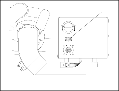
TP-6069 6/03 25Section 6 Electrical System
6.7 Remote Start Switch
Connection
Kohler Co. offers several remote panels for connection
to the generator set. Contact your local Kohlerr
distributor/dealer for detailed descriptions. See
Figure 6-8 for remote start panel connection to the
generator set controller. Kohler Co. also offers a wiring
harness with a connector keyed to the controller box
connector. The other end of this harness has pigtails
that the installer can use to connect to a
customer-supplied start/stop switch or separate lights
and hourmeter. Consult wiring diagrams and instruction
sheets for connection information/details.
1
DA-250000-H
1. Controller remote connector
Figure 6-8 Controller Remote Connector, Typical
Note: Gauge senders. Gauge senders are available
for most generator sets. If using customer-
supplied gauges, be sure they are compatible
with generator set senders. Contact an
authorized Kohlerrservice distributor/dealer.
Gauges and senders are available as service
items from an authorized Kohlerrservice
distributor/dealer.
33--150 kW Models: Various wiring harnesses,
Y-connectors, pigtail harnesses, remote control panels,
and remote annunciator panels (Decision-Makert3+
only) are available. See Figure 6-9 and Figure 6-10 for
wiring options.
3.5EFOZ/4EOZ Models: See Figure 7-3 for the
optional remote panel wiring.
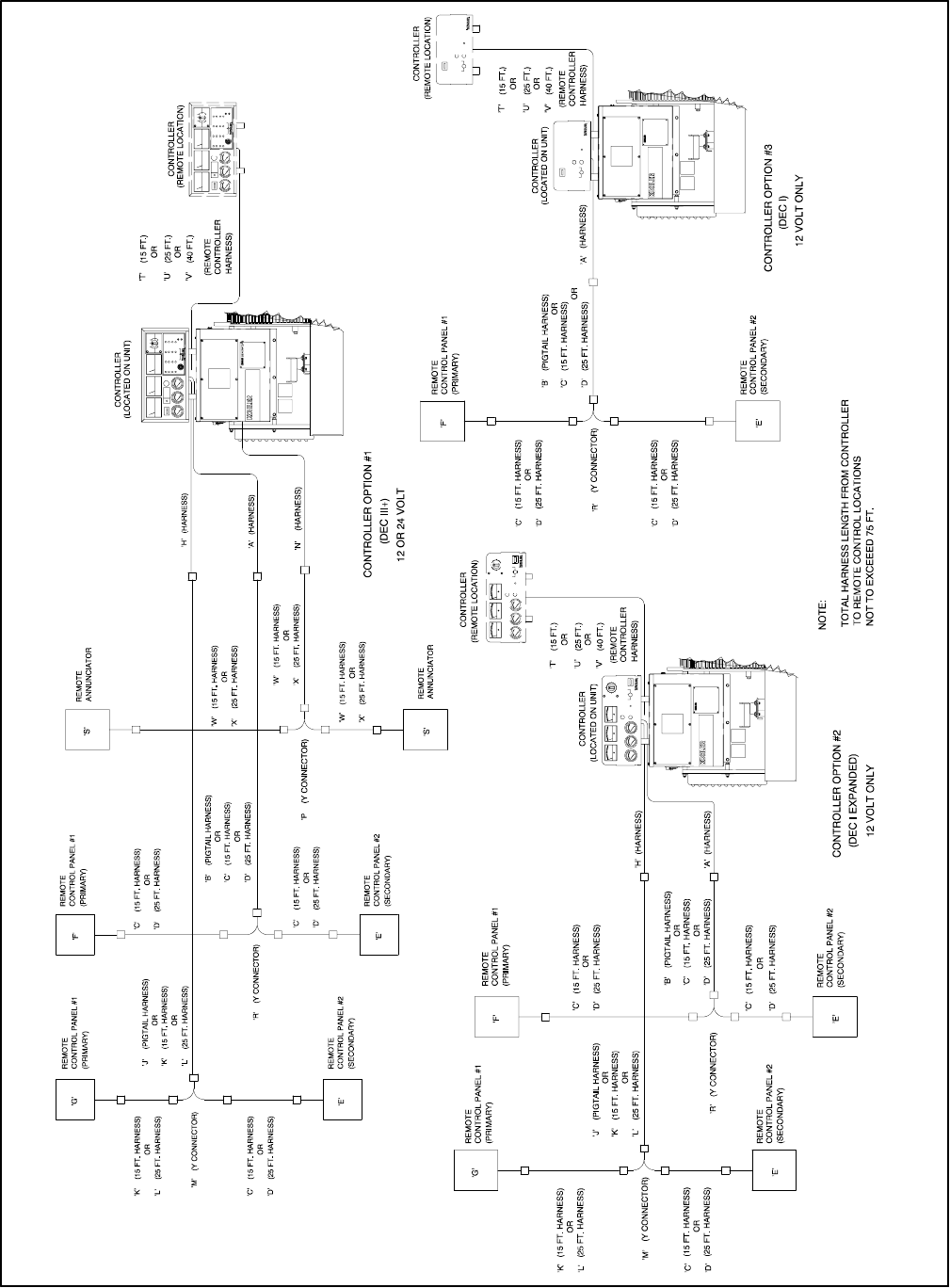
TP-6069 6/0326 Section 6 Electrical System
ADV--6115A-A
Figure 6-9 Remote Controller and Harness Options (33--150 kW Models)
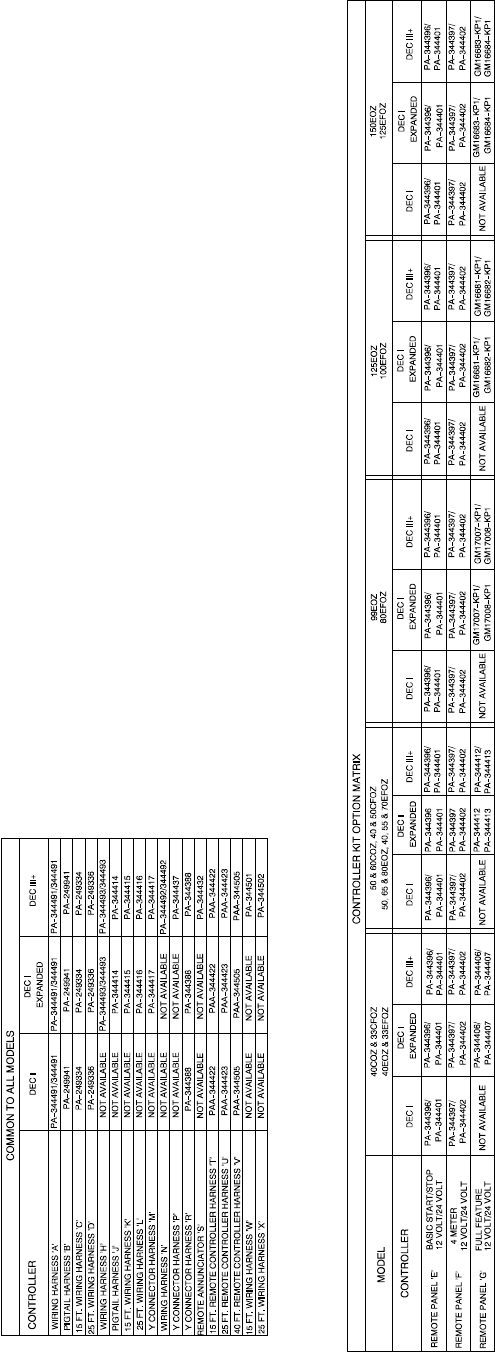
TP-6069 6/03 27Section 6 Electrical System
Figure 6-10 Remote Controller and Harness Options (33--150 kW Models)
TP-6069 6/0328 Section 6 Electrical System
Notes

TP-6069 6/03 29Section 7 Installation Drawings
Section 7 Installation Drawings
Use the drawings in this section for installation
purposes. Consult the supplier and verify that the
drawings are the most current for your specifications.
Installation drawings show exhaust outlet locations, fuel
inlet and return connections, siphon break locations,
and battery connections. See Figure 7-1 for installation
drawing identification.
Model No. Drawing Page
3.5EFOZ and 4EOZ ADV-6652A-B 30
with remote options ADV-6652B-B 31
4EFOZ and 5EOZ ADV-5850A-H 32
with sound shield ADV-5850B-H 33
6.5EFOZ and 8EOZ ADV-6284A-J 34
with sound shield ADV-6284B-J 35
8.5/9EFOZ and 10EOZ ADV-6026A-K 36
with sound shield ADV-6026B-K 37
11EFOZ and 13EOZ ADV-6512A-D 38
with sound shield ADV-6512B-D 39
11.5/13EFOZ and 14/15.5EOZ ADV-6513A-C 40
with sound shield ADV-6513B-C 41
16/17.5EFOZ and 20EOZ ADV-6481A-D 42
with sound shield ADV-6481B-D 43
19/20EFOZ and 23/24EOZ ADV-6494A-C 44
with sound shield ADV-6494B-C 45
23/27EFOZ and 28/32EOZ ADV-6285A-F 46
with sound shield ADV-6285B-F 47
33EFOZ and 40EOZ ADV-6581A-E 48
with fuel/water separator
and dry exhaust elbow ADV-6581B-E 49
with sound shield ADV-6581C-E 50
with electric clutch ADV-6581D-E 51
40EFOZ and 50EOZ ADV-6582A-E 52
with fuel/water separator
and dry exhaust elbow ADV-6582B-E 53
with sound shield ADV-6582C-E 54
with electric clutch ADV-6582D-E 55
55EFOZ and 65EOZ ADV-6583A-E 56
with fuel/water separator
and dry exhaust elbow ADV-6583B-E 57
with sound shield ADV-6583C-E 58
with electric clutch ADV-6583D-E 59
70/80EFOZ and 80/99EOZ ADV-6603A-D 60
with fuel/water separator
and dry exhaust elbow ADV-6603B-D 61
with sound shield ADV-6603C-D 62
with electric clutch ADV-6603D-D 63
100/125EFOZ and 125/150EOZ ADV-6594A-D 64
with sound shield ADV-6594B-D 65
with dry exhaust elbow ADV-6594C-D 66
Figure 7-1 Installation Drawings
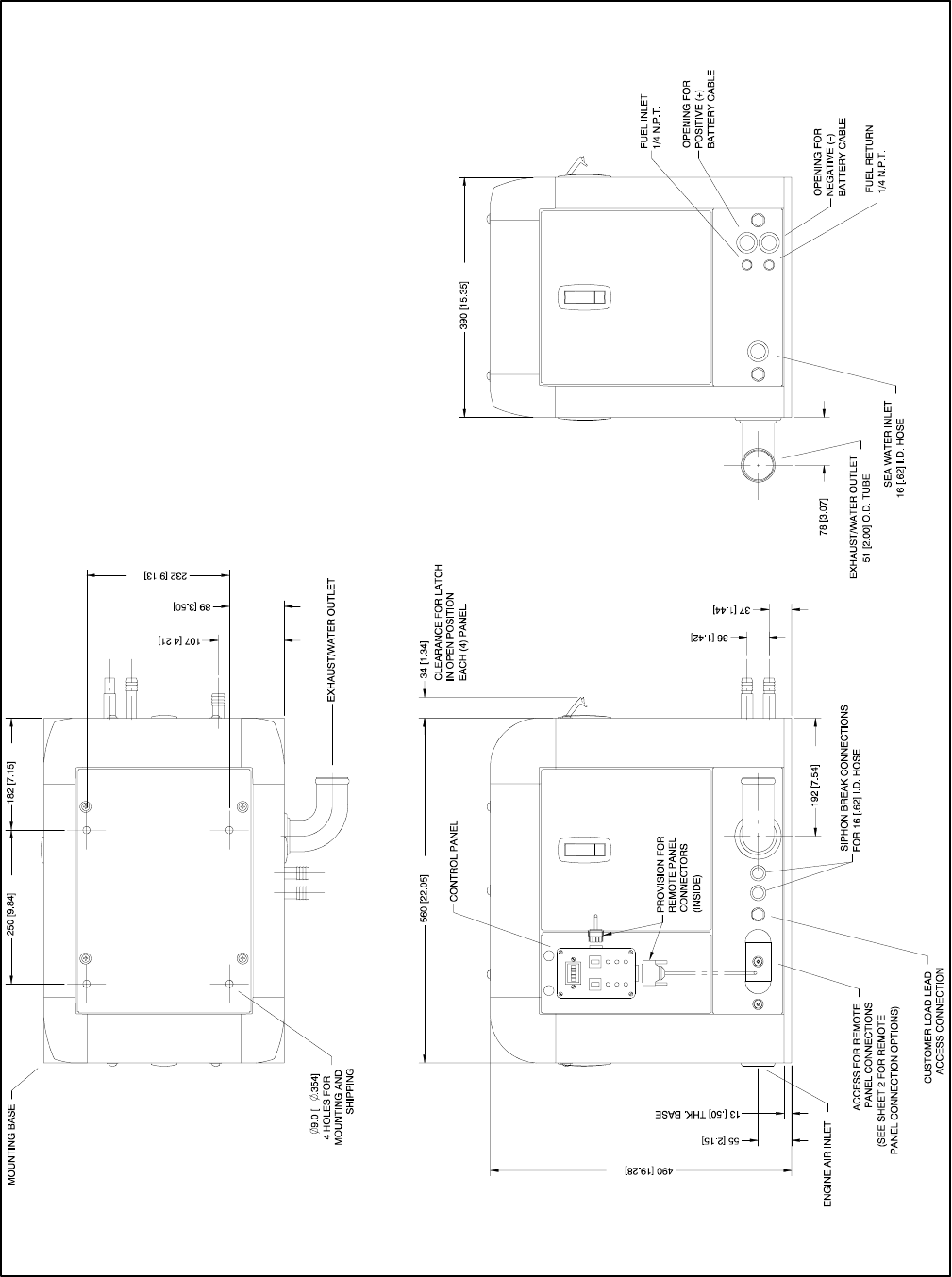
TP-6069 6/0330 Section 7 Installation Drawings
ADV-6652A-B
NOTE: Dimensions in [ ] are inch equivalents.
Figure 7-2 Dimension Drawing, 3.5EFOZ/4EOZ

TP-6069 6/03 31Section 7 Installation Drawings
ADV-6652B-B
Figure 7-3 Remote Options, 3.5EFOZ/4EOZ
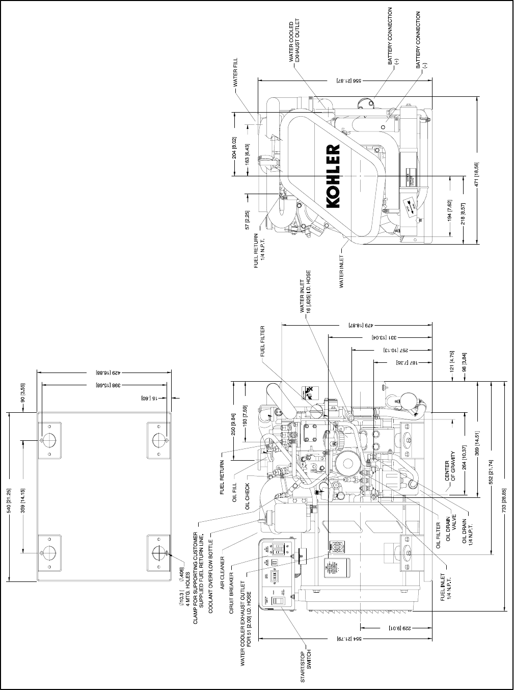
TP-6069 6/0332 Section 7 Installation Drawings
ADV-5850A-H
NOTE: Dimensions in [ ] are inch equivalents.
Figure 7-4 Dimension Drawing, 4EFOZ/5EOZ
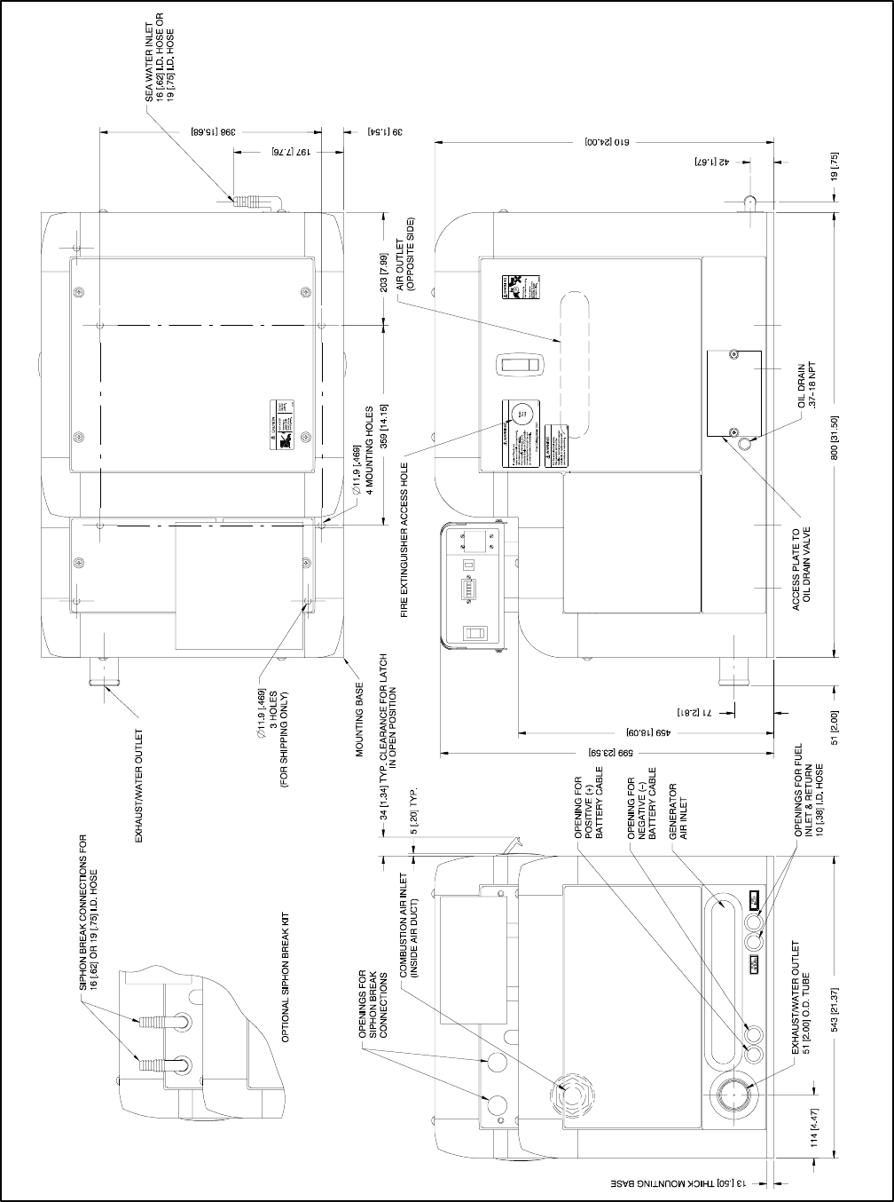
TP-6069 6/03 33Section 7 Installation Drawings
ADV-5850B-H
NOTE: Dimensions in [ ] are inch equivalents.
Figure 7-5 Dimension Drawing, 4EFOZ/5EOZ with Sound Shield
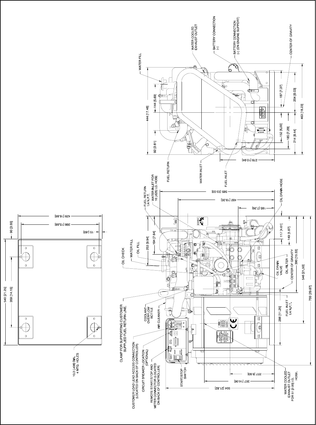
TP-6069 6/0334 Section 7 Installation Drawings
ADV-6284A-J
NOTE: Dimensions in [ ] are inch equivalents.
Figure 7-6 Dimension Drawing, 6.5EFOZ/8EOZ
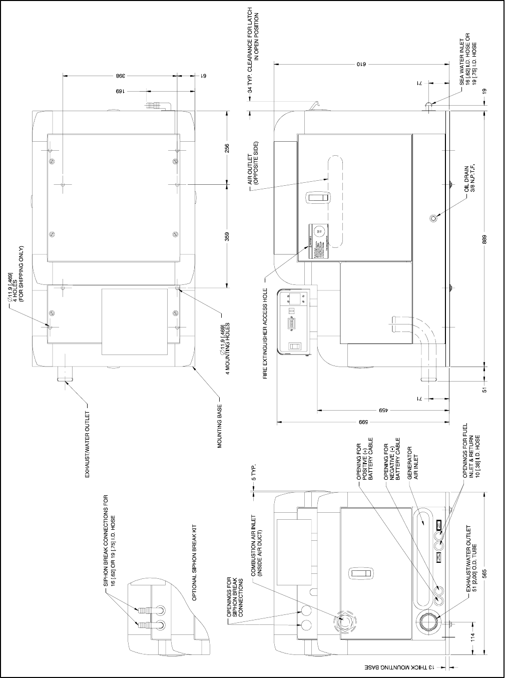
TP-6069 6/03 35Section 7 Installation Drawings
ADV-6284B-J
NOTE: Dimensions in [ ] are inch equivalents.
Figure 7-7 Dimension Drawing, 6.5EFOZ/8EOZ with Sound Shield
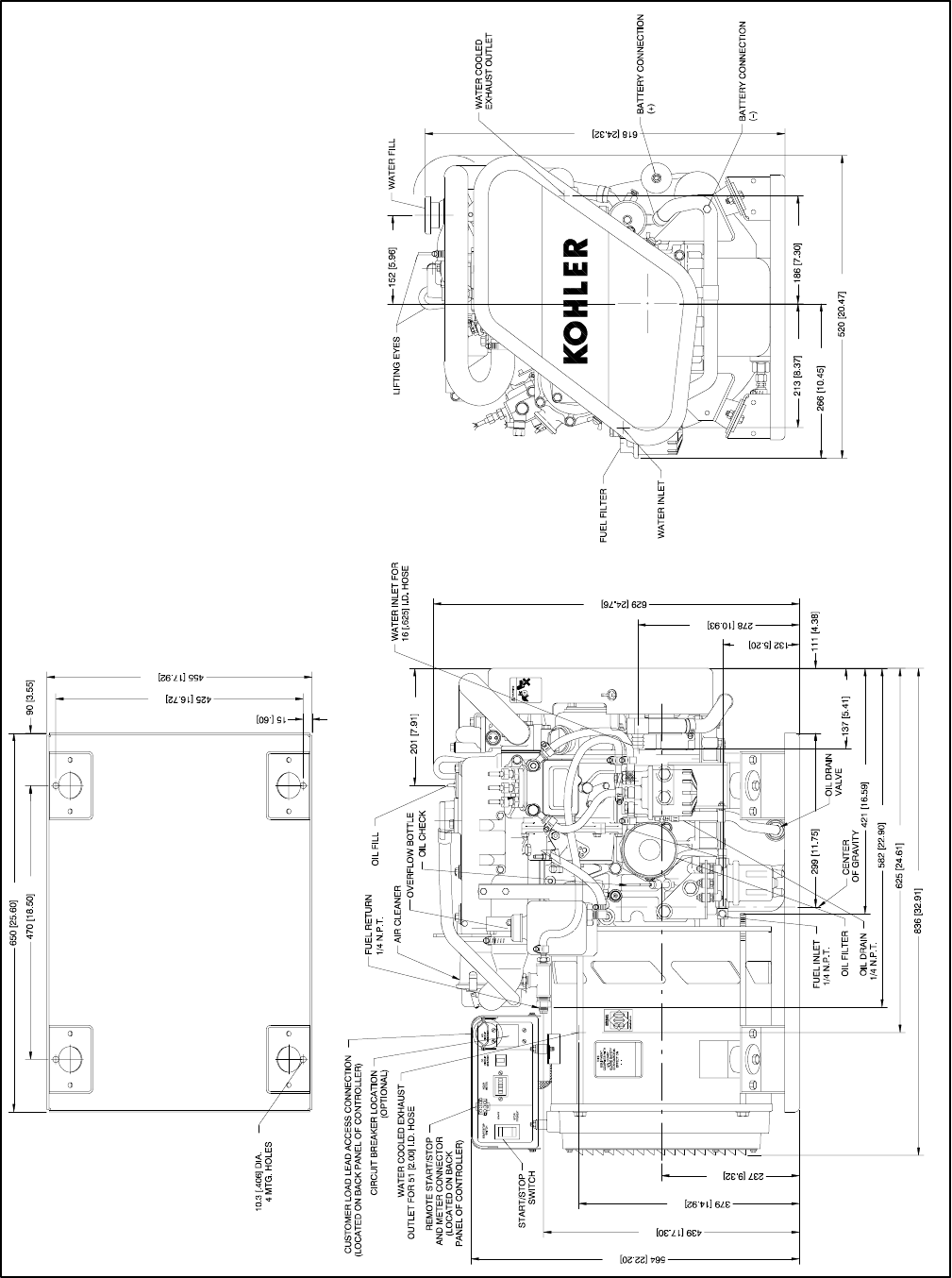
TP-6069 6/0336 Section 7 Installation Drawings
ADV-6026A-K
NOTE: Dimensions in [ ] are inch equivalents.
Figure 7-8 Dimension Drawing, 8.5/9EFOZ and 10EOZ
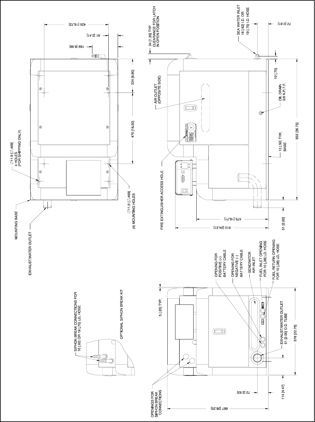
TP-6069 6/03 37Section 7 Installation Drawings
ADV-6026B-K
NOTE: Dimensions in [ ] are inch equivalents.
Figure 7-9 Dimension Drawing, 8.5/9EFOZ and 10EOZ with Sound Shield
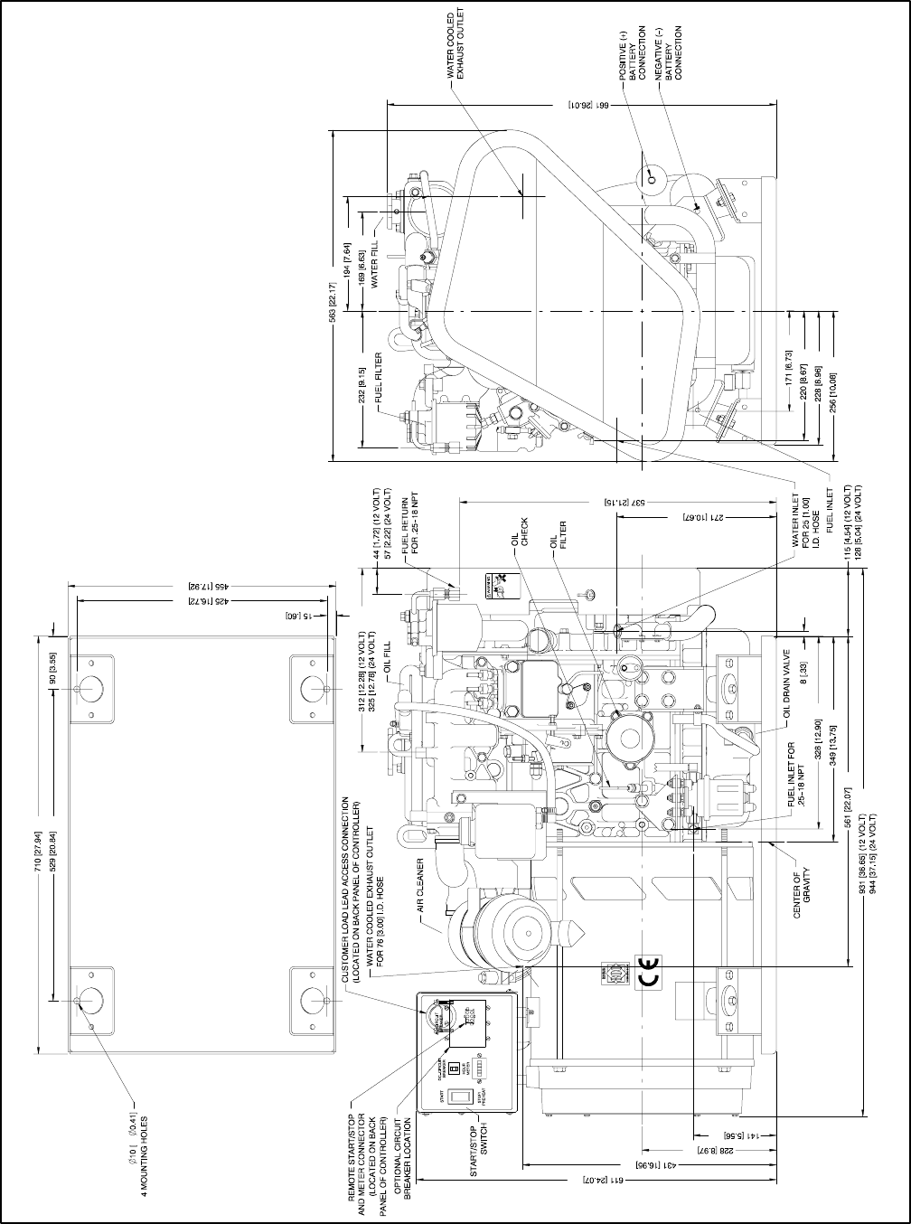
TP-6069 6/0338 Section 7 Installation Drawings
ADV-6512A-D
NOTE: Dimensions in [ ] are inch equivalents.
Figure 7-10 Dimension Drawing, 11EFOZ/13EOZ

TP-6069 6/03 39Section 7 Installation Drawings
ADV-6512B-D
NOTE: Dimensions in [ ] are inch equivalents.
Figure 7-11 Dimension Drawing, 11EFOZ/13EOZ with Sound Shield
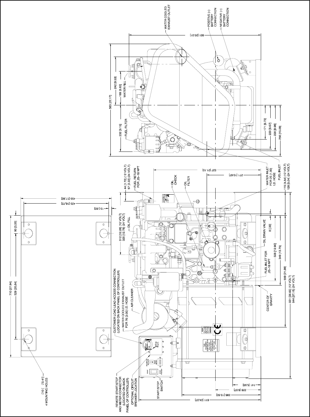
TP-6069 6/0340 Section 7 Installation Drawings
ADV-6513A-C
NOTE: Dimensions in [ ] are inch equivalents.
Figure 7-12 Dimension Drawing, 11.5/13EFOZ and 14/15.5EOZ
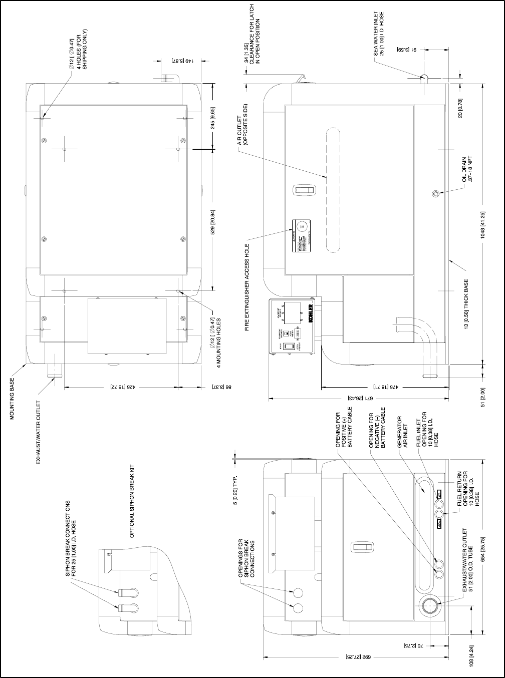
TP-6069 6/03 41Section 7 Installation Drawings
ADV-6513B-C
NOTE: Dimensions in [ ] are inch equivalents.
Figure 7-13 Dimension Drawing, 11.5/13EFOZ and 14/15.5EOZ with Sound Shield
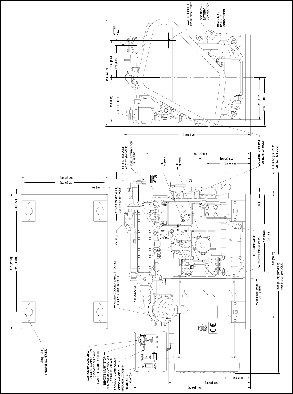
TP-6069 6/0342 Section 7 Installation Drawings
ADV-6481A-D
NOTE: Dimensions in [ ] are inch equivalents.
Figure 7-14 Dimension Drawing, 16/17.5EFOZ and 20EOZ
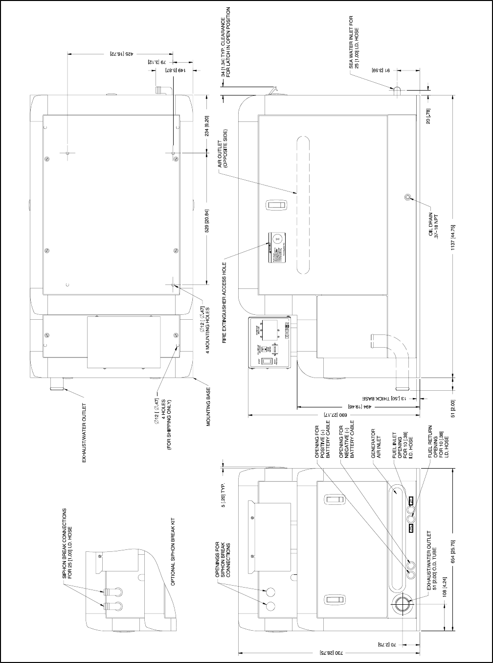
TP-6069 6/03 43Section 7 Installation Drawings
ADV-6481B-D
NOTE: Dimensions in [ ] are inch equivalents.
Figure 7-15 Dimension Drawing, 16/17.5EFOZ and 20EOZ with Sound Shield
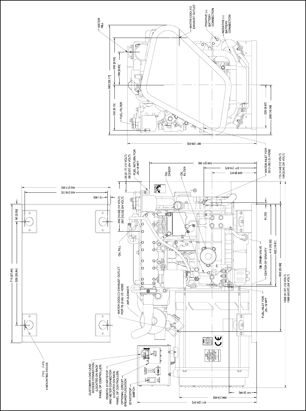
TP-6069 6/0344 Section 7 Installation Drawings
ADV-6494A-C
NOTE: Dimensions in [ ] are inch equivalents.
Figure 7-16 Dimension Drawing, 19/20EFOZ and 23/24EOZ
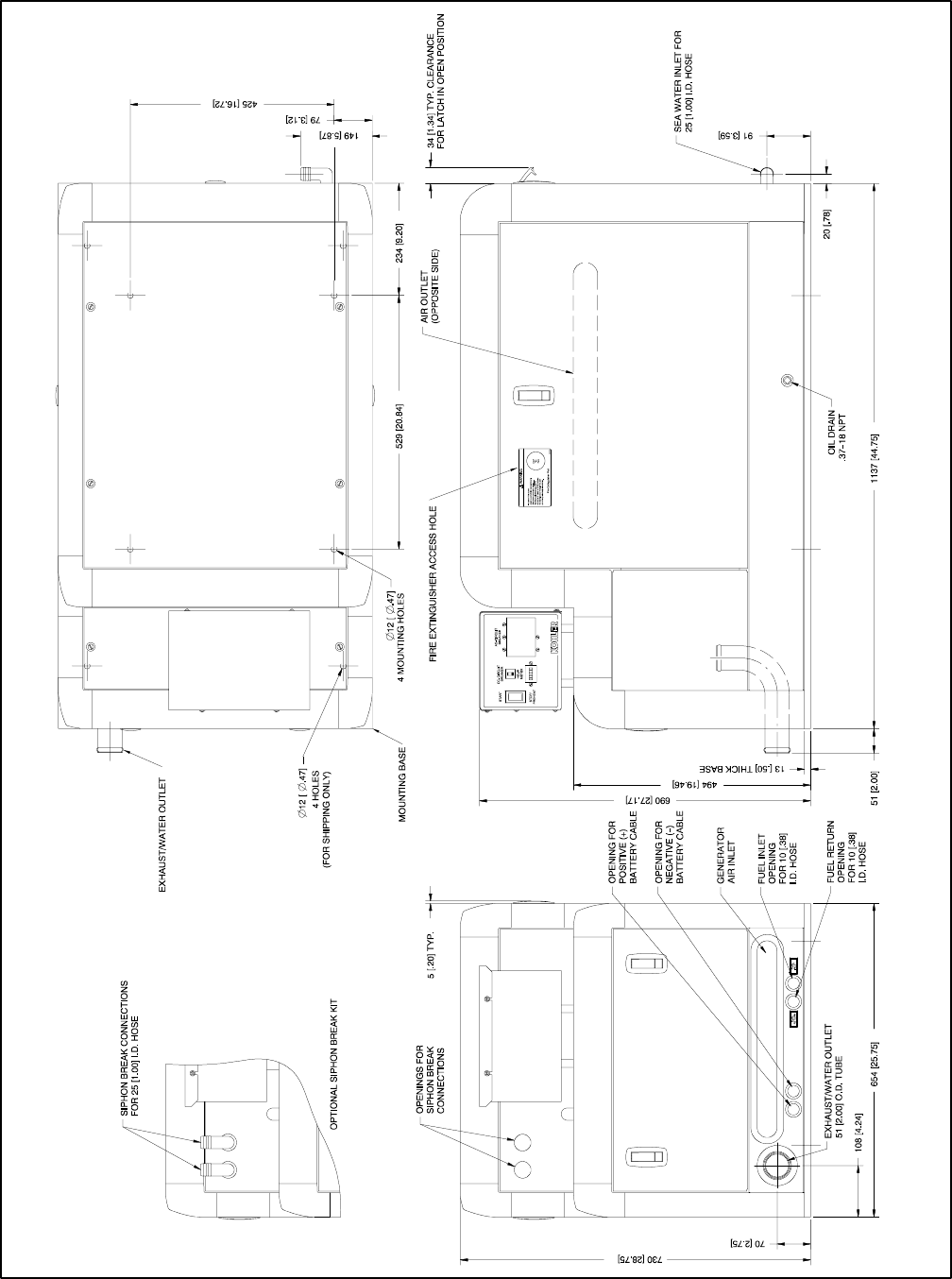
TP-6069 6/03 45Section 7 Installation Drawings
ADV-6494B-C
NOTE: Dimensions in [ ] are inch equivalents.
Figure 7-17 Dimension Drawing, 19/20EFOZ and 23/24EOZ with Sound Shield
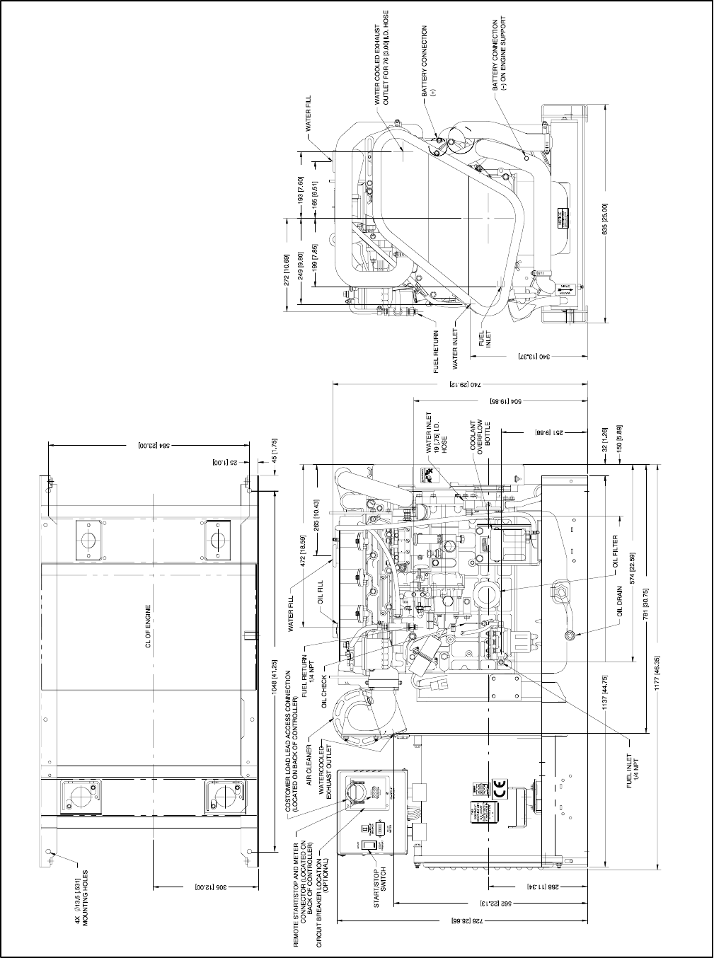
TP-6069 6/0346 Section 7 Installation Drawings
ADV-6285A-F
NOTE: Dimensions in [ ] are inch equivalents.
Figure 7-18 Dimension Drawing, 23/27EFOZ and 28/32EOZ
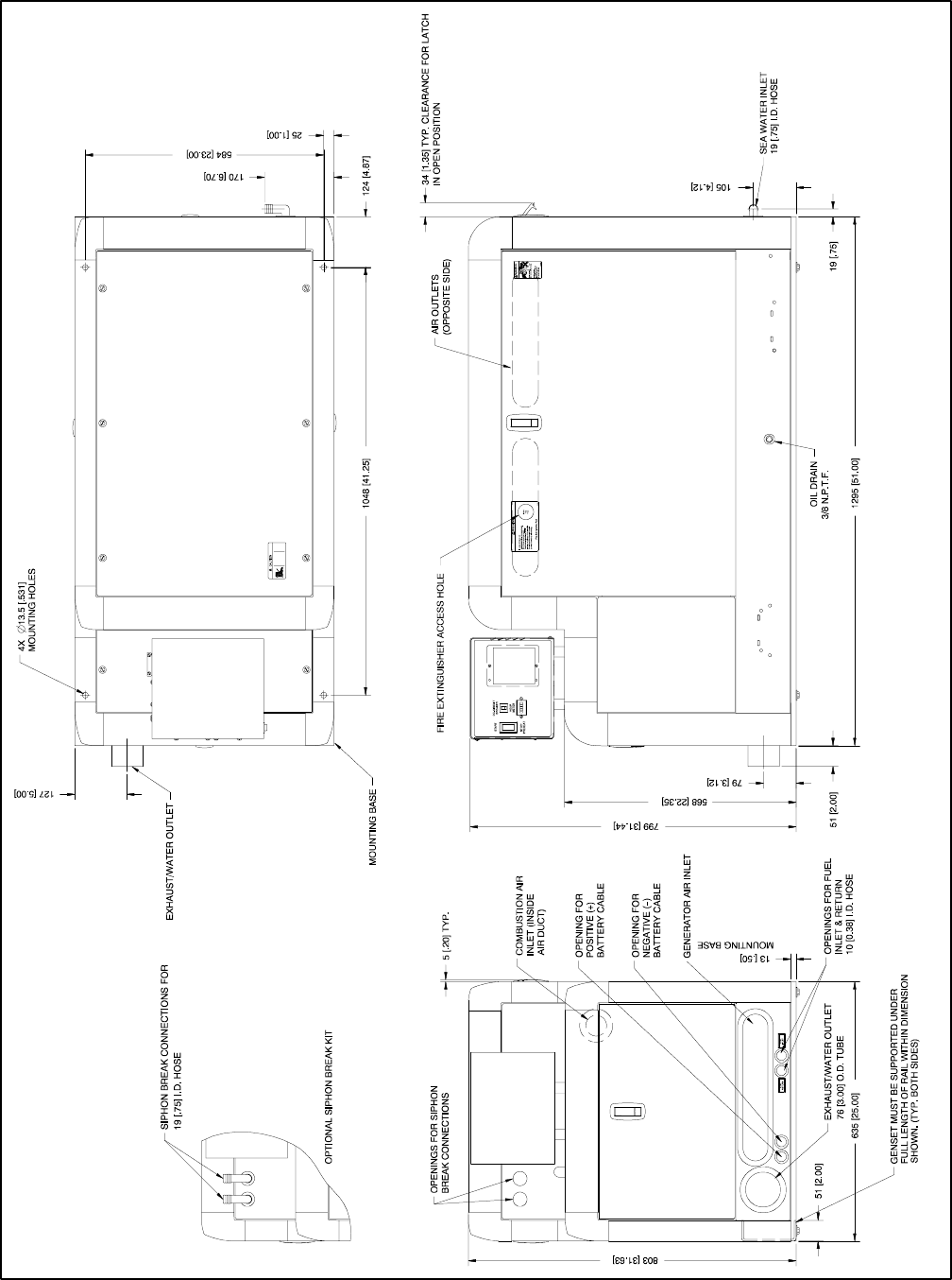
TP-6069 6/03 47Section 7 Installation Drawings
ADV-6285B-F
NOTE: Dimensions in [ ] are inch equivalents.
Figure 7-19 Dimension Drawing, 23/27EFOZ and 28/32EOZ with Sound Shield
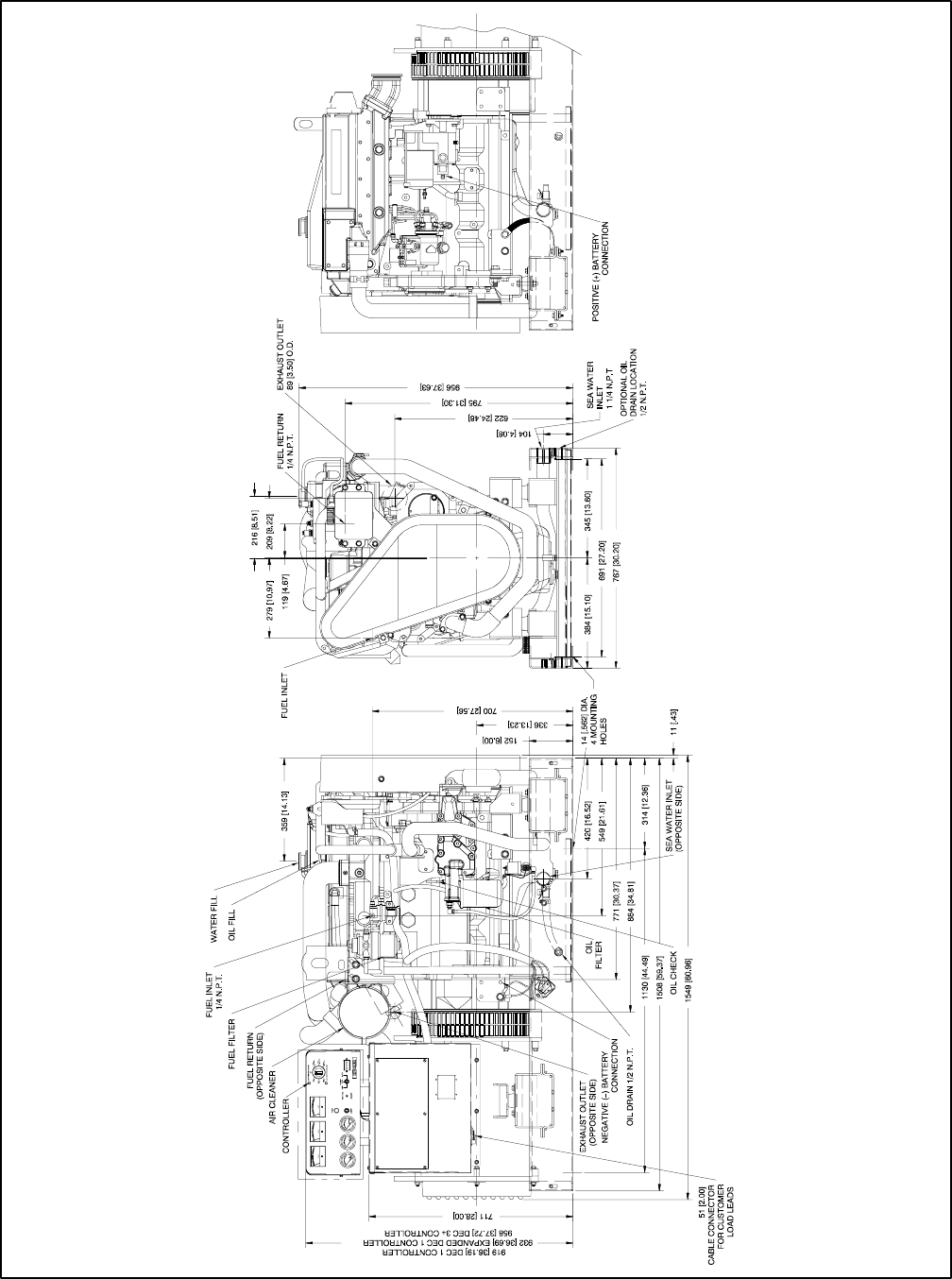
TP-6069 6/0348 Section 7 Installation Drawings
ADV-6581A-E
NOTE: Dimensions in [ ] are inch equivalents.
Figure 7-20 Dimension Drawing, 33EFOZ/40EOZ
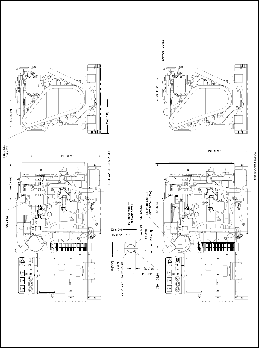
TP-6069 6/03 49Section 7 Installation Drawings
ADV-6581B-E
NOTE: Dimensions in [ ] are inch equivalents.
Figure 7-21 Dimension Drawing, 33EFOZ/40EOZ with Fuel/Water Separator and Dry Exhaust Elbow
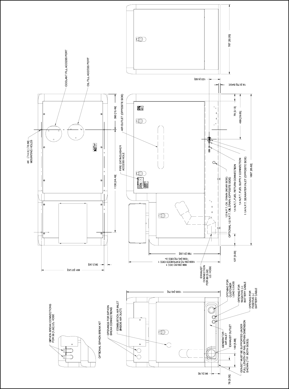
TP-6069 6/0350 Section 7 Installation Drawings
ADV-6581C-E
NOTE: Dimensions in [ ] are inch equivalents.
Figure 7-22 Dimension Drawing, 33EFOZ/40EOZ with Sound Shield
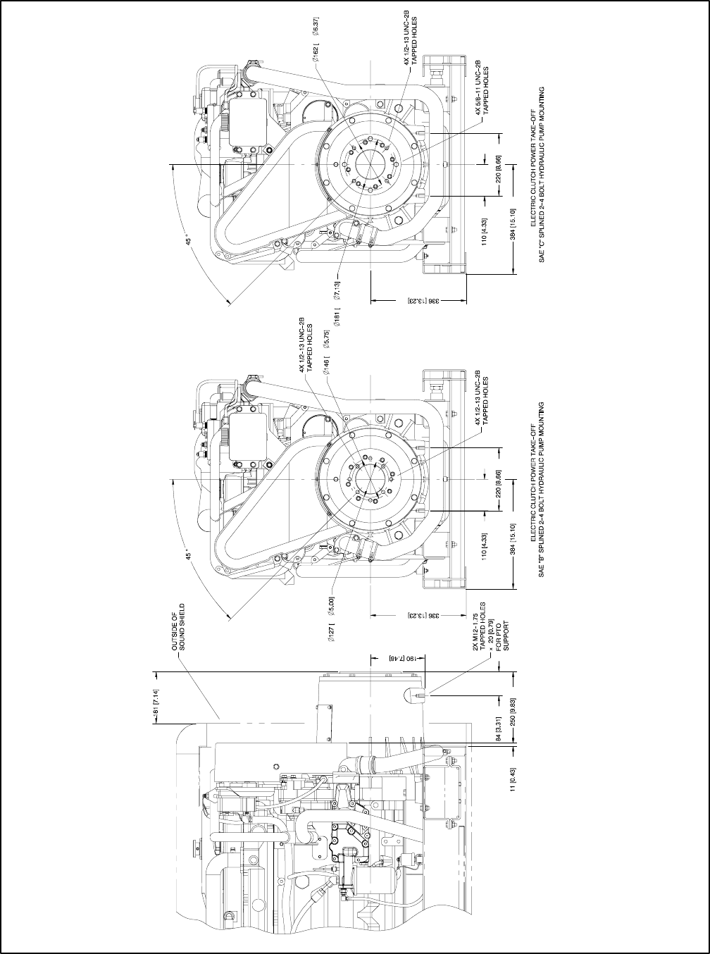
TP-6069 6/03 51Section 7 Installation Drawings
ADV-6581D-E
NOTE: Dimensions in [ ] are inch equivalents.
Figure 7-23 Dimension Drawing, 33EFOZ/40EOZ with Electric Clutch
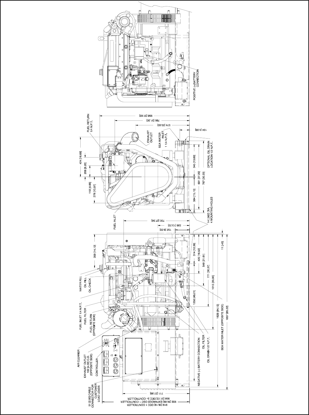
TP-6069 6/0352 Section 7 Installation Drawings
ADV-6582A-E
NOTE: Dimensions in [ ] are inch equivalents.
Figure 7-24 Dimension Drawing, 40EFOZ/50EOZ
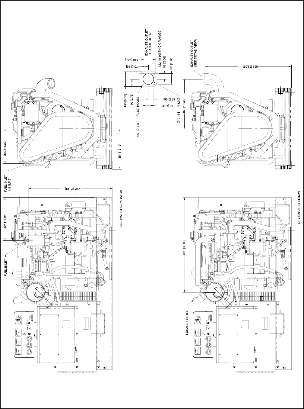
TP-6069 6/03 53Section 7 Installation Drawings
ADV-6582B-E
NOTE: Dimensions in [ ] are inch equivalents.
Figure 7-25 Dimension Drawing, 40EFOZ/50EOZ with Fuel/Water Separator and Dry Exhaust Elbow
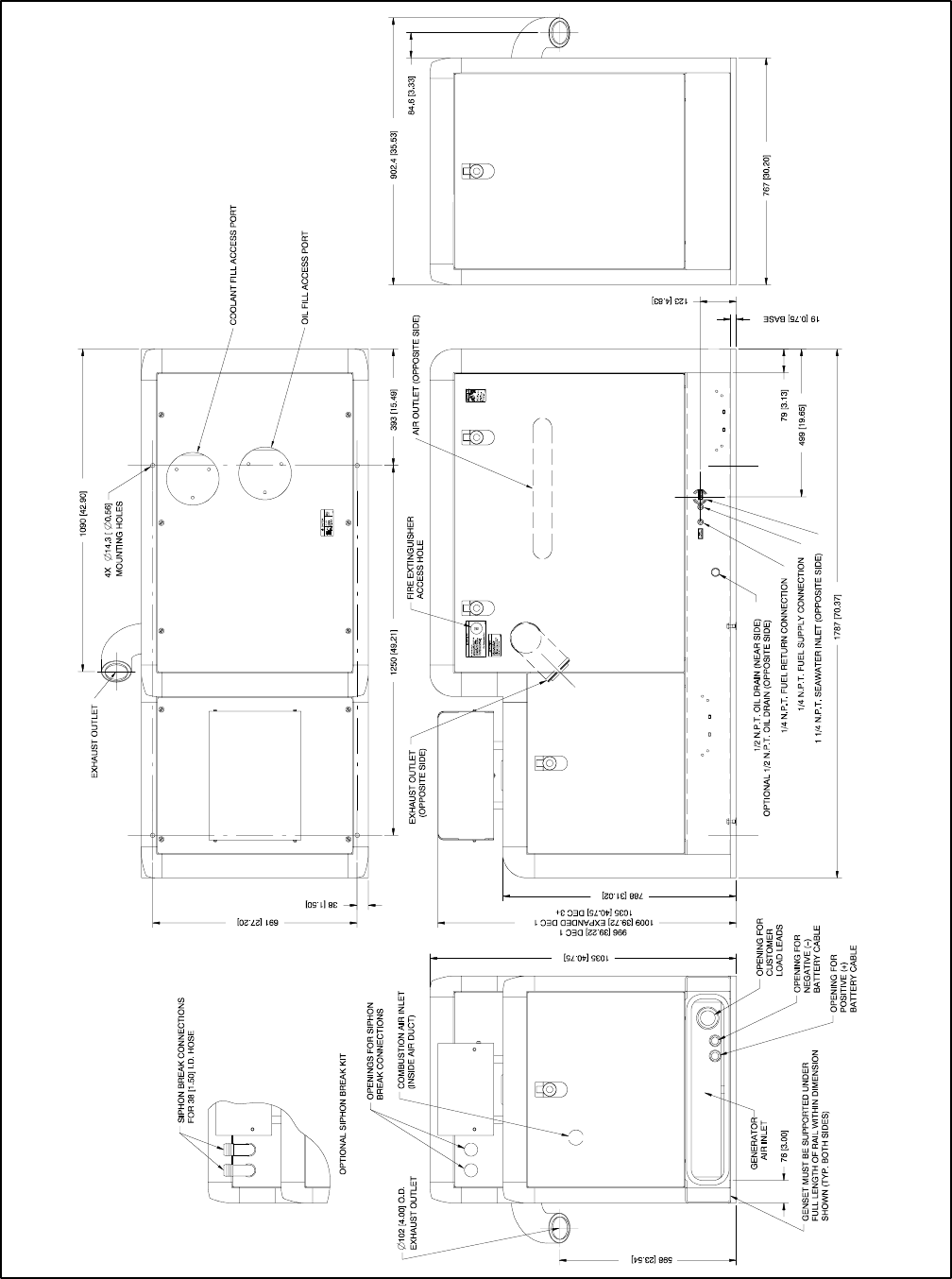
TP-6069 6/0354 Section 7 Installation Drawings
ADV-6582C-E
NOTE: Dimensions in [ ] are inch equivalents.
Figure 7-26 Dimension Drawing, 40EFOZ/50EOZ with Sound Shield
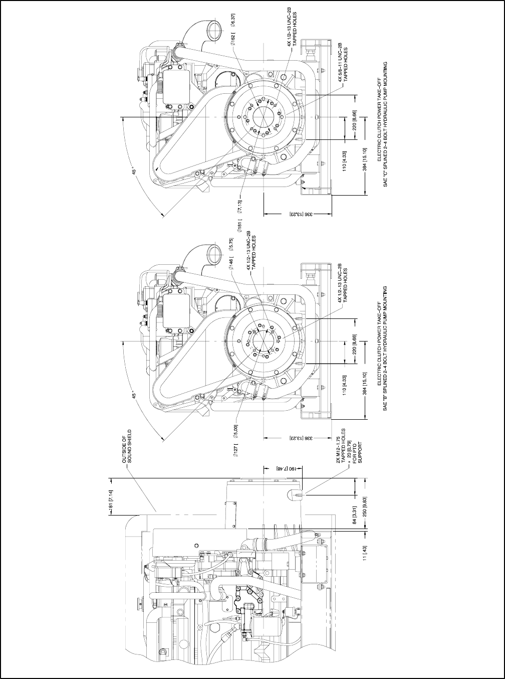
TP-6069 6/03 55Section 7 Installation Drawings
ADV-6582D-E
NOTE: Dimensions in [ ] are inch equivalents.
Figure 7-27 Dimension Drawing, 40EFOZ/50EOZ with Electric Clutch
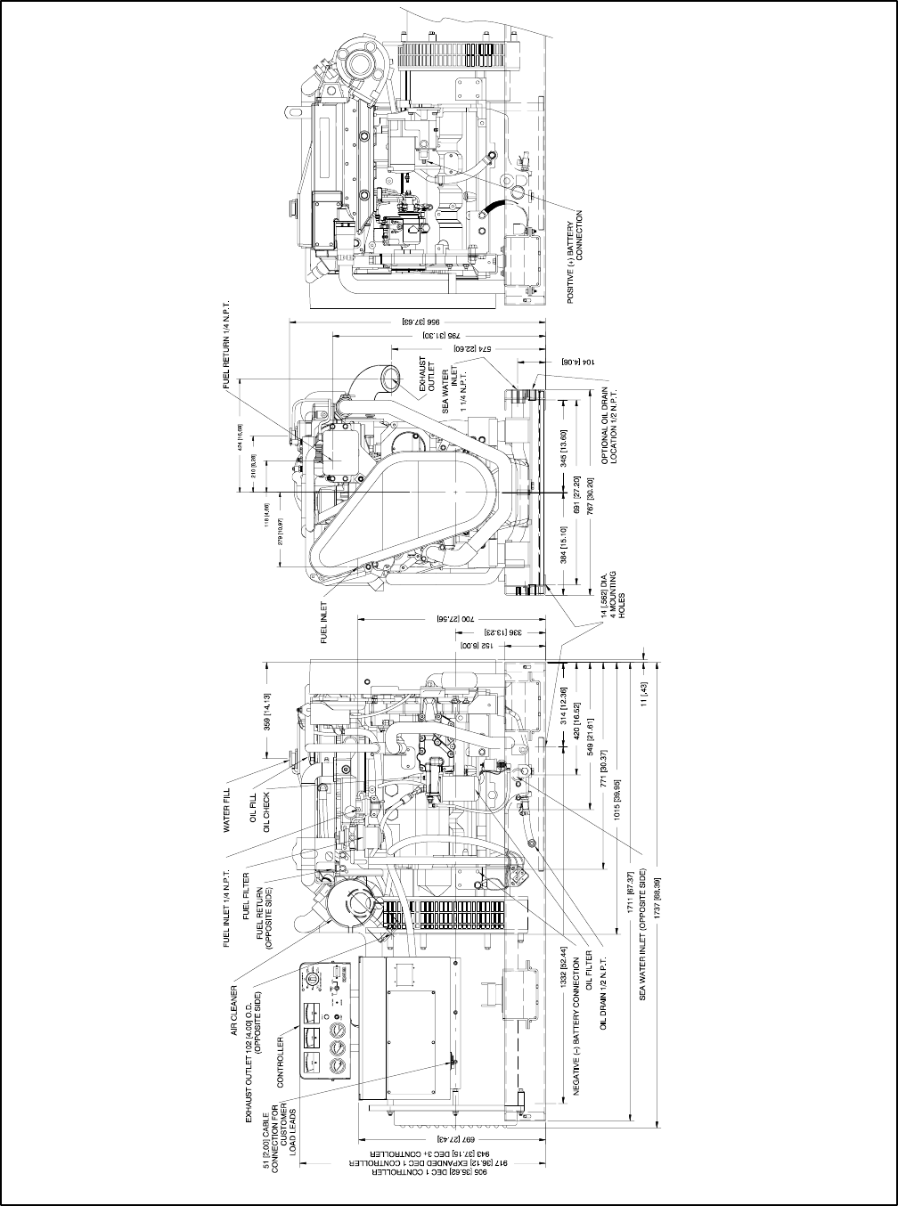
TP-6069 6/0356 Section 7 Installation Drawings
ADV-6583A-E
NOTE: Dimensions in [ ] are inch equivalents.
Figure 7-28 Dimension Drawing, 55EFOZ/65EOZ
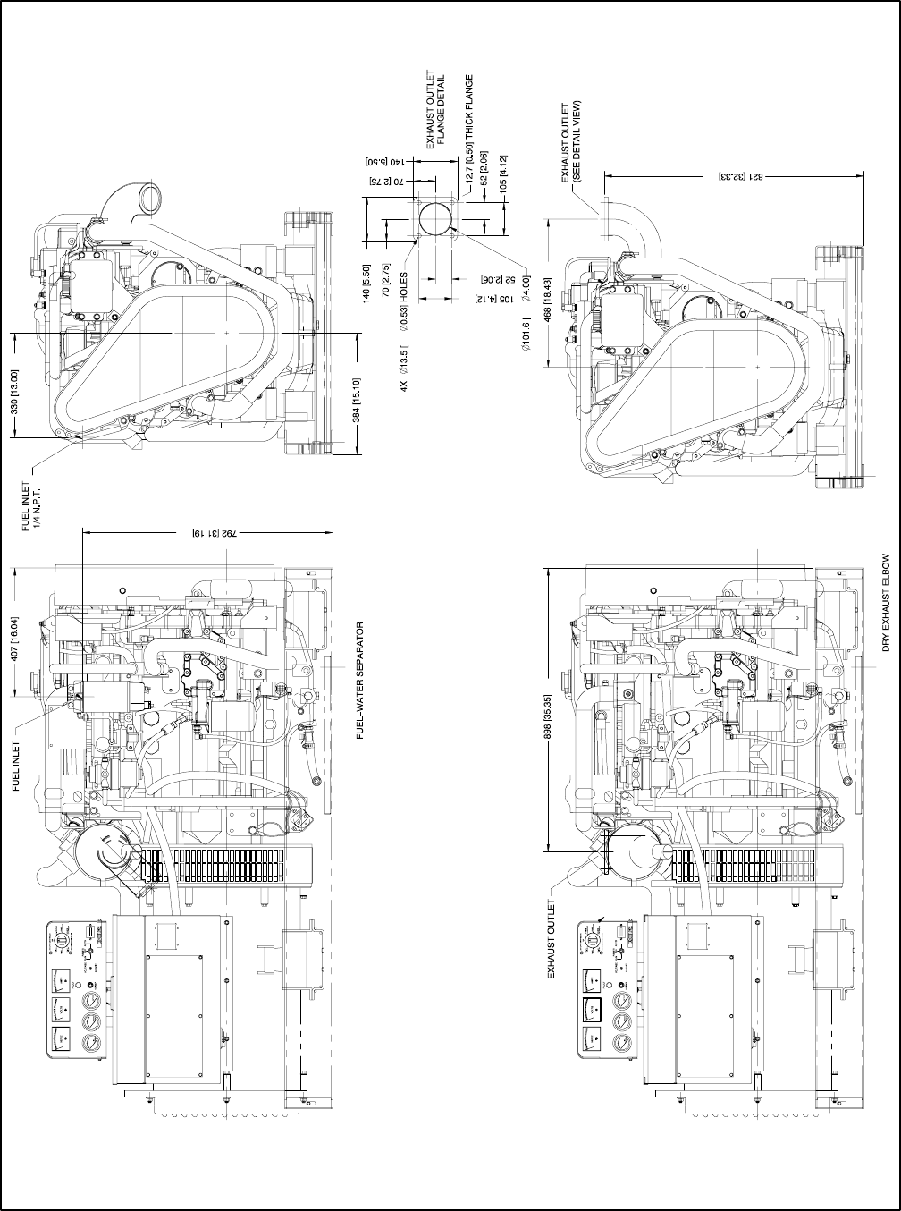
TP-6069 6/03 57Section 7 Installation Drawings
ADV-6583B-E
NOTE: Dimensions in [ ] are inch equivalents.
Figure 7-29 Dimension Drawing, 55EFOZ/65EOZ with Fuel/Water Separator and Dry Exhaust Elbow
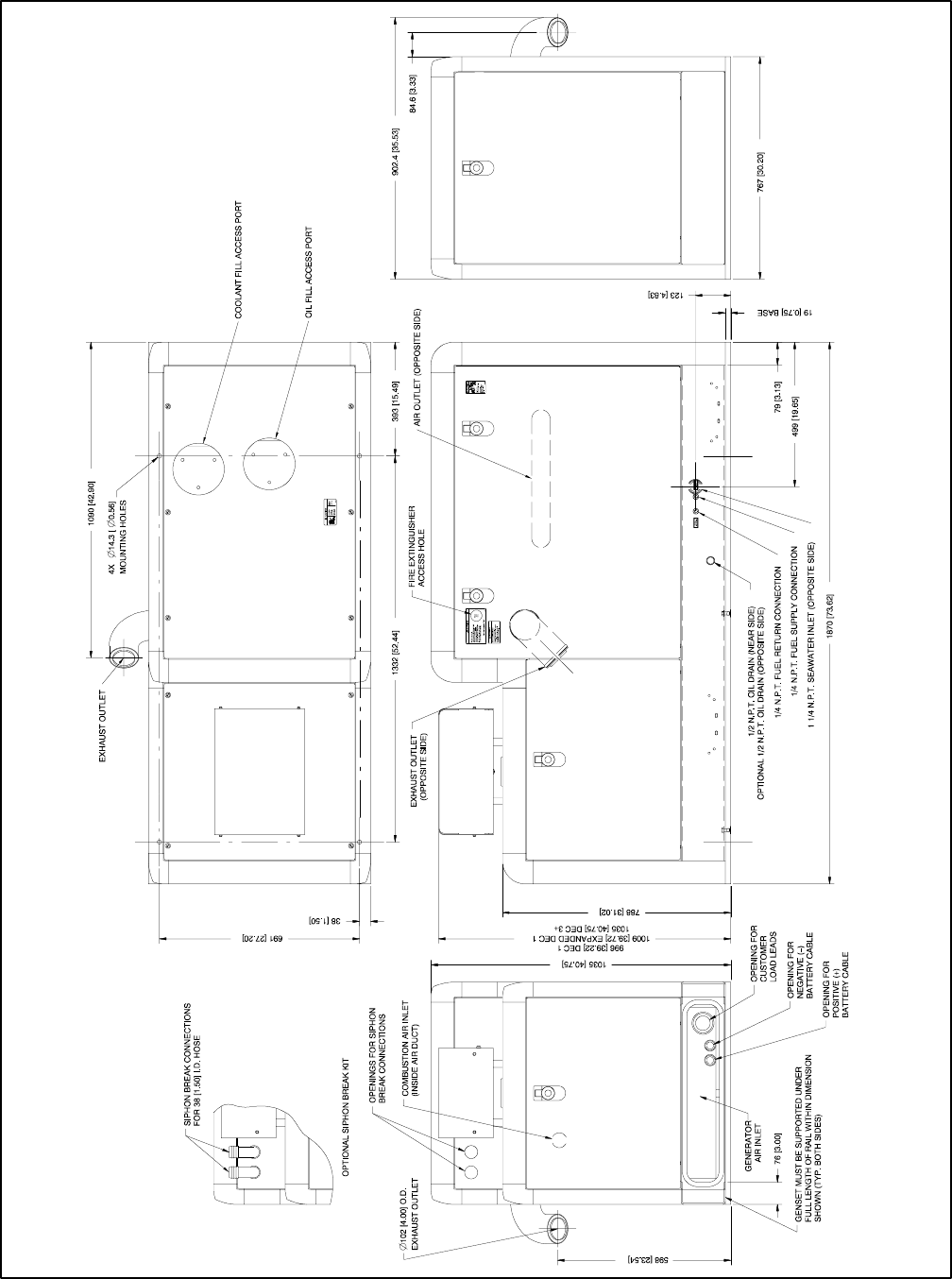
TP-6069 6/0358 Section 7 Installation Drawings
ADV-6583C-E
NOTE: Dimensions in [ ] are inch equivalents.
Figure 7-30 Dimension Drawing, 55EFOZ/65EOZ with Sound Shield
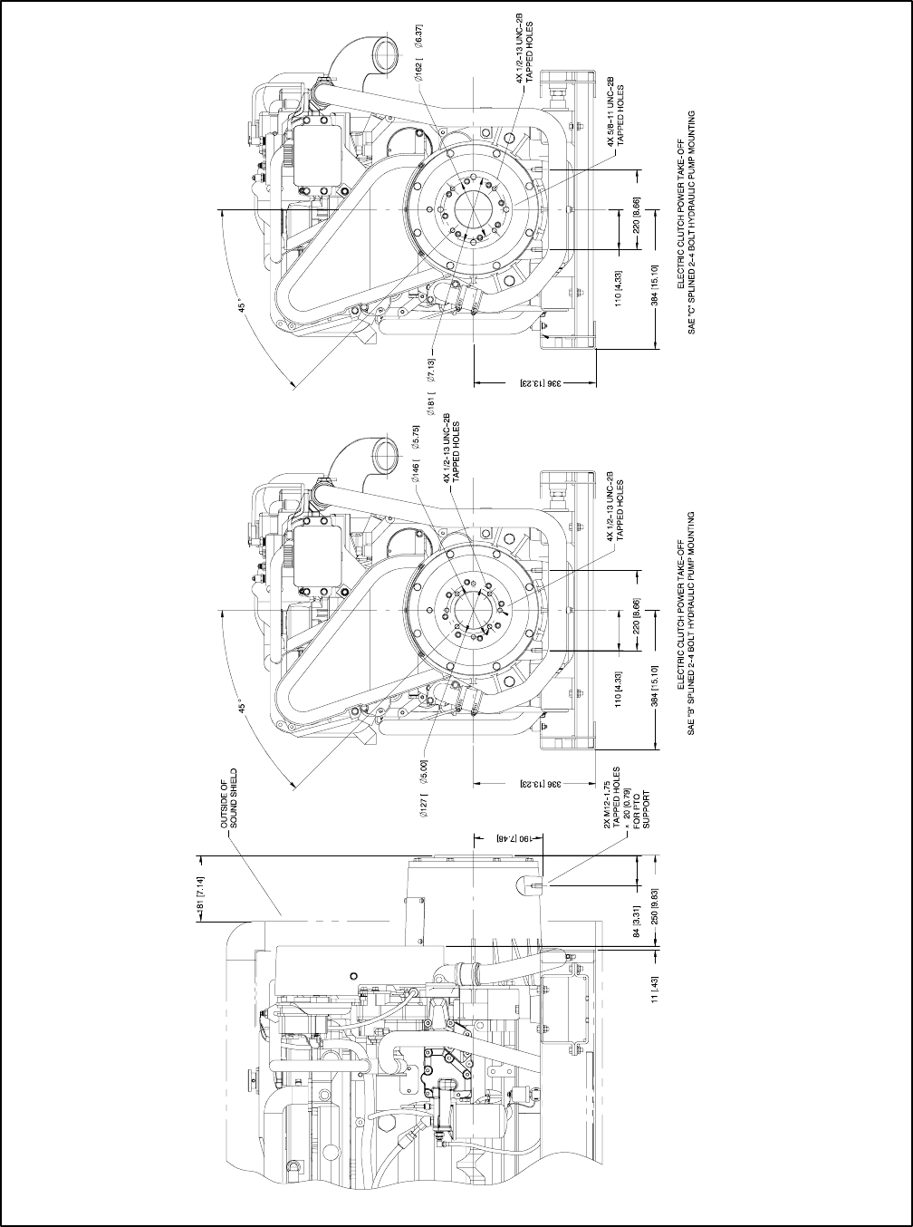
TP-6069 6/03 59Section 7 Installation Drawings
ADV-6583D-E
NOTE: Dimensions in [ ] are inch equivalents.
Figure 7-31 Dimension Drawing, 55EFOZ/65EOZ with Electric Clutch
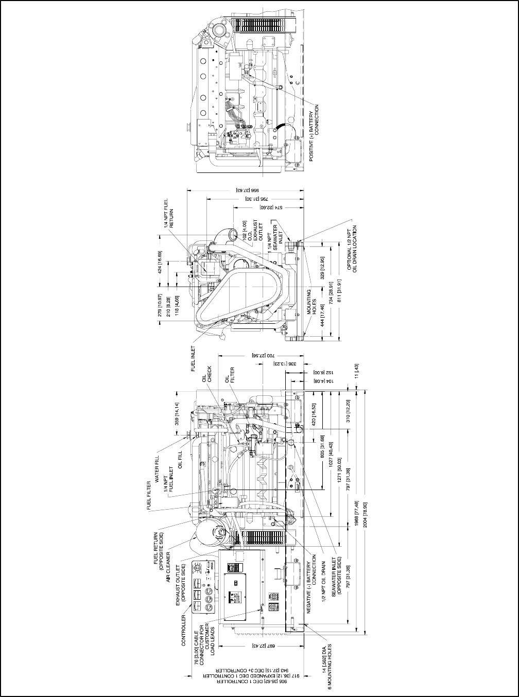
TP-6069 6/0360 Section 7 Installation Drawings
ADV-6603A-D
NOTE: Dimensions in [ ] are inch equivalents.
Figure 7-32 Dimension Drawing, 70/80EFOZ and 80/99EOZ
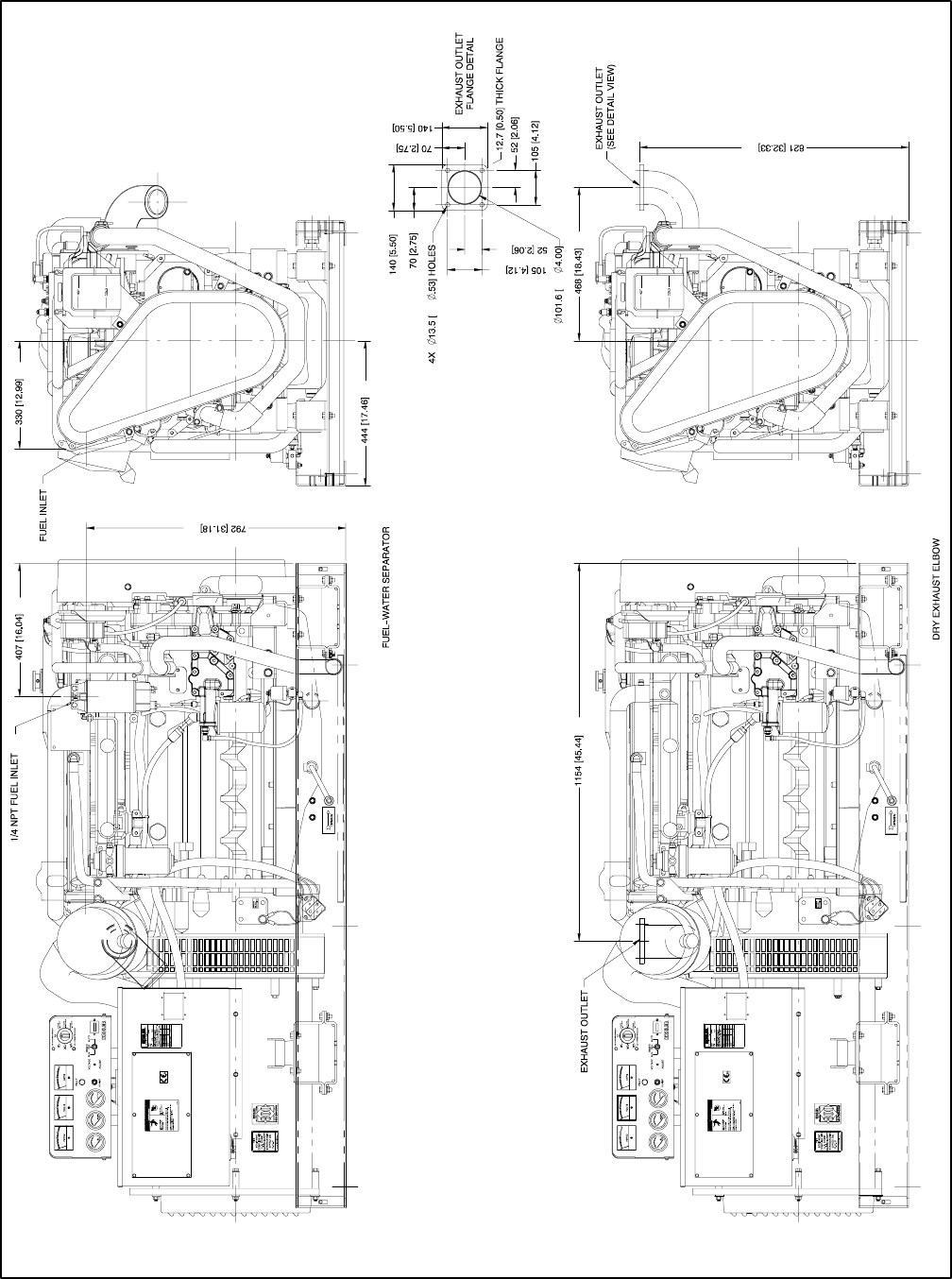
TP-6069 6/03 61Section 7 Installation Drawings
ADV-6603B-D
NOTE: Dimensions in [ ] are inch equivalents.
Figure 7-33 Dimension Drawing, 70/80EFOZ and 80/99EOZ with Fuel/Water Separator and Dry Exhaust Elbow
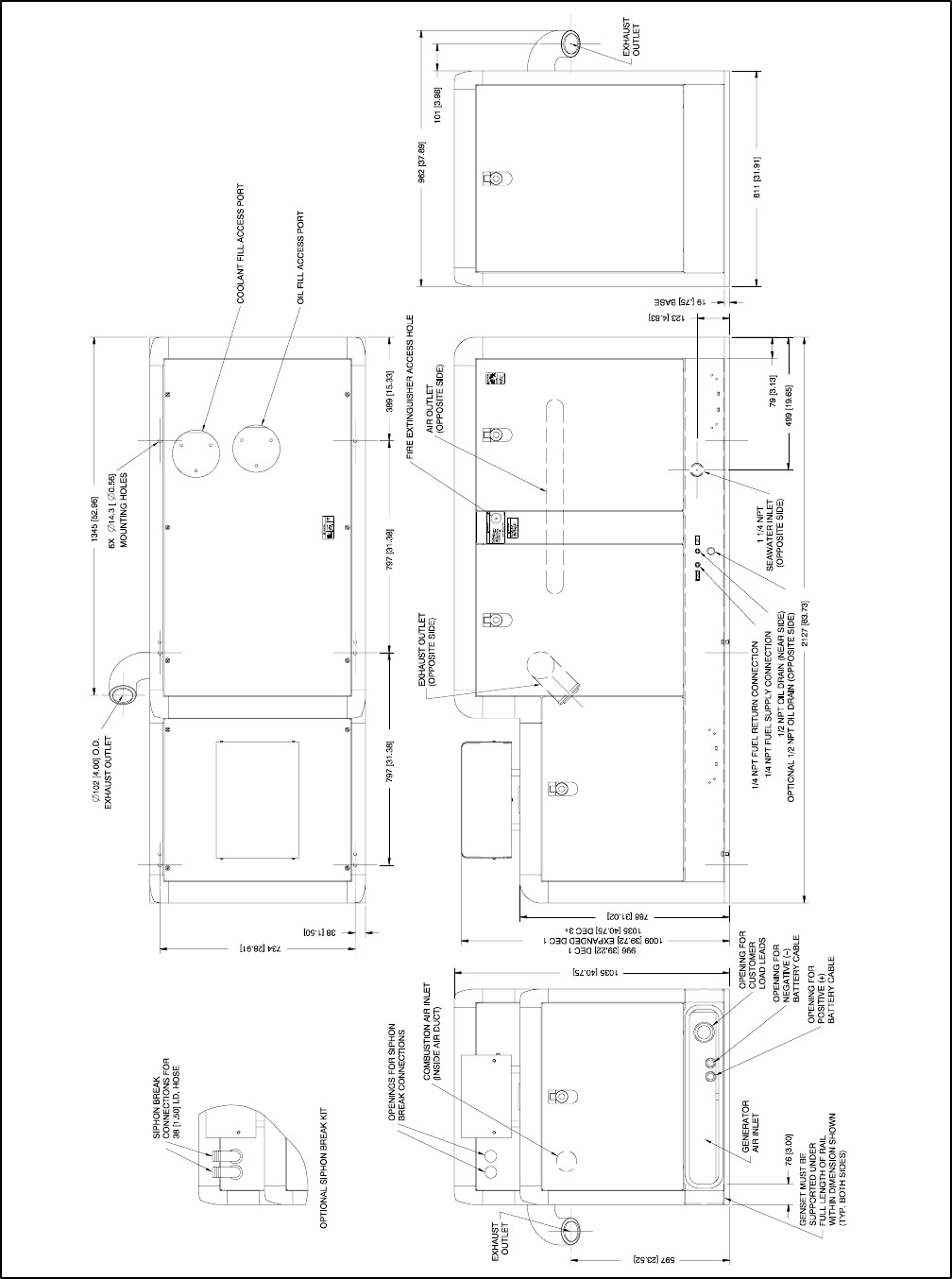
TP-6069 6/0362 Section 7 Installation Drawings
ADV-6603C-D
NOTE: Dimensions in [ ] are inch equivalents.
Figure 7-34 Dimension Drawing, 70/80EFOZ and 80/99EOZ with Sound Shield
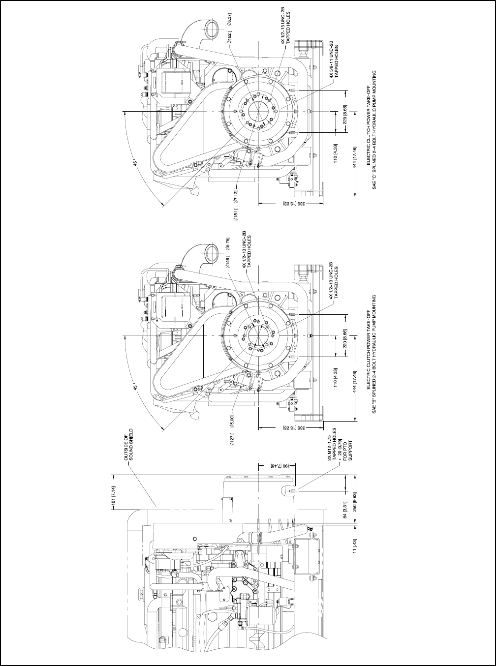
TP-6069 6/03 63Section 7 Installation Drawings
ADV-6603D-D
NOTE: Dimensions in [ ] are inch equivalents.
Figure 7-35 Dimension Drawing, 70/80EFOZ and 80/99EOZ with Electric Clutch
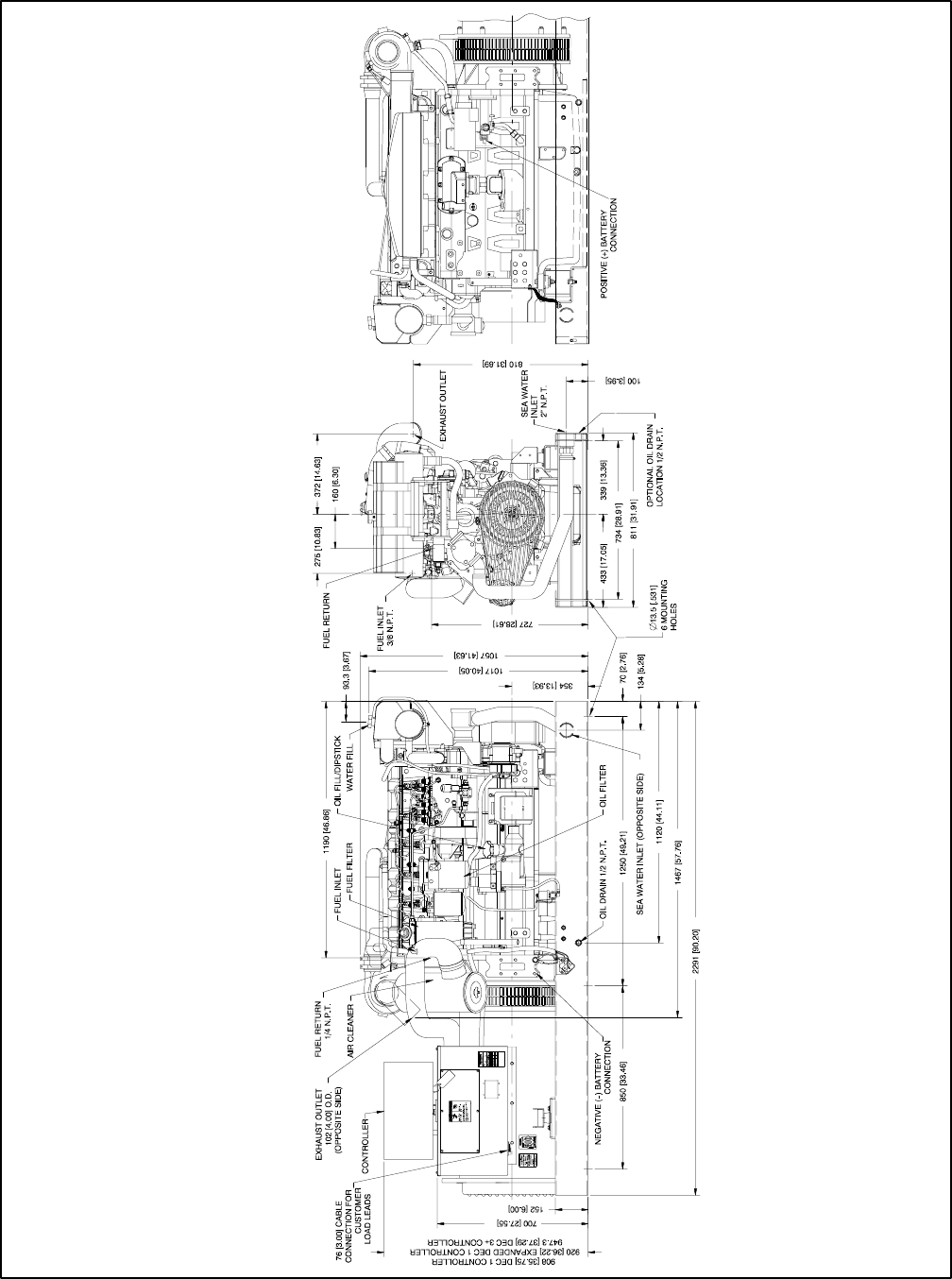
TP-6069 6/0364 Section 7 Installation Drawings
ADV-6594A-D
NOTE: Dimensions in [ ] are inch equivalents.
Figure 7-36 Dimension Drawing, 100/125EFOZ and 125/150EOZ
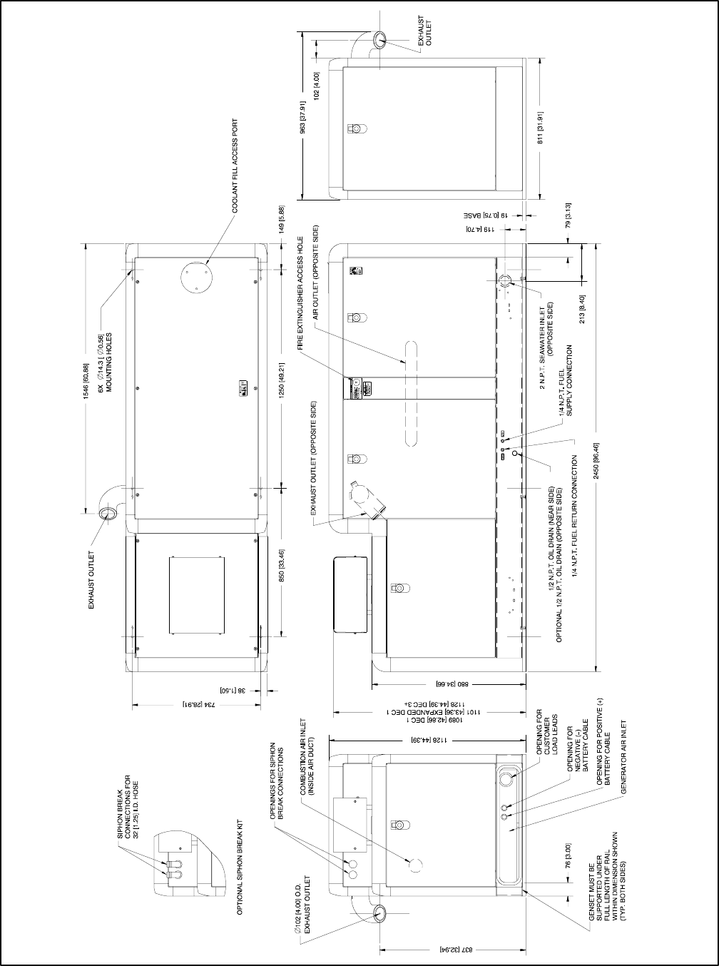
TP-6069 6/03 65Section 7 Installation Drawings
ADV-6594B-D
NOTE: Dimensions in [ ] are inch equivalents.
Figure 7-37 Dimension Drawing, 100/125EFOZ and 125/150EOZ with Sound Shield
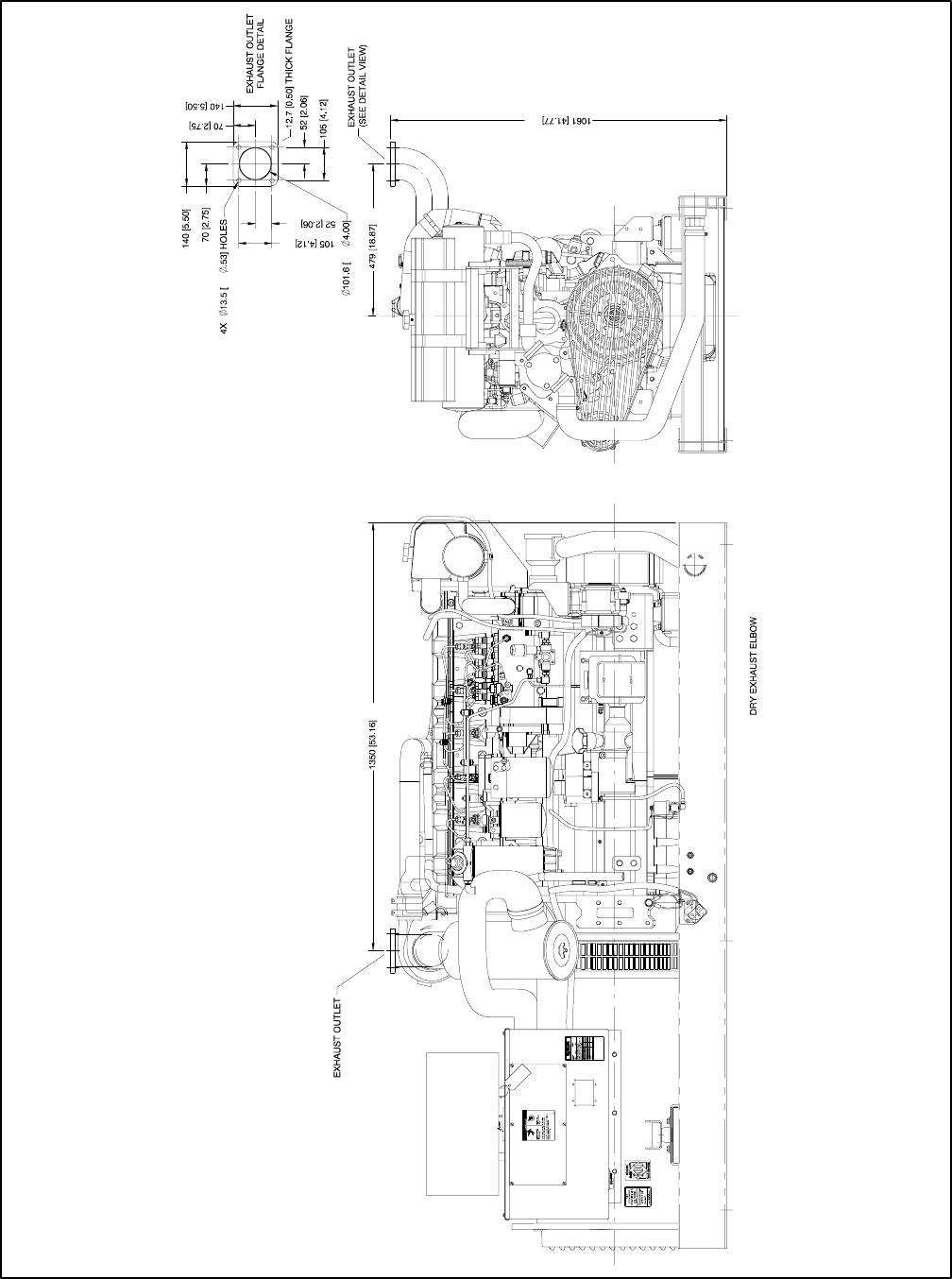
TP-6069 6/0366 Section 7 Installation Drawings
ADV-6594C-D
NOTE: Dimensions in [ ] are inch equivalents.
Figure 7-38 Dimension Drawing, 100/125EFOZ and 125/150EOZ with Dry Exhaust Elbow
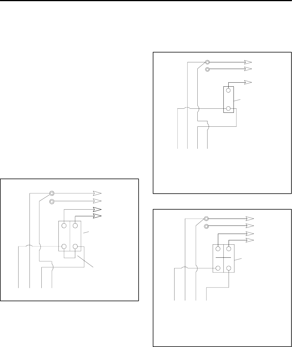
TP-6069 6/03 67Section 8 Reconnection/Adjustments
Section 8 Reconnection/Adjustments
8.1 Four-Lead Reconnection
The following information illustrates the reconnection of
four-lead generator sets. In all cases, conform to the
National Electrical Code (NEC).
NOTICE
Voltage reconnection. Affix a notice to the generator set after
reconnecting the set to a voltage different from the voltage on
the nameplate. Order voltage reconnection decal 246242
from an authorized service distributor/dealer.
8.1.1 100--120-Volt Configurations
If the installation requires a factory two-pole circuit
breaker, do not connect the load-side terminals of the
circuit breaker together; see Figure 8-1. If the
installation requires a 100--120-volt, 2-wire system, use
a single-pole circuit breaker. See Figure 8-2. When
connecting stator phase leads together, size the output
lead (L1) to handle the amperage. Use a jumper lead on
the line side of the circuit breaker to balance the load of
the generator set.
GRD.
L1
L2
4321
L0 (Neutral) L0
Ground
Load
Side
Line
Side
Two-Pole
Circuit
Breaker
Jumper
lead
Figure 8-1 100--120-Volt, 3-Wire Configuration
8.1.2 100--120/200--240-Volt
Configurations
The 100--120/200--240-volt configuration does not use
a jumper lead. If the unit was originally wired for straight
100--120 volt, 3-wire, remove the jumper lead (see
Figure 8-1 for location). Select a two-pole circuit
breaker. Application of two single-pole circuit breakers
does not conform to NEC requirements for supplying a
200--240-volt load, even if the breakers are
mechanically attached together. Leads L1 and L2 are
for different phases; never connect them together.
4321
Stator Leads
L0
GRD.
L1
L0 (Neutral)
Line
Side
Single-Pole
Circuit
Breaker
Ground
Load
Side
60 Hz 50 Hz
L0--L1 100--120 Volt 100--120 Volt
L0--L2 100--120 Volt 100--120 Volt
Figure 8-2 100--120-Volt, 2-Wire Configuration
4321
Stator Leads
L0
GRD.
L2
L1
L0 (Neutral)
Line
Side
Factory
Two-Pole
Circuit
Breaker
Ground
Load
Side
100--120/200--240-Volt,
3-Wire
60 Hz 50 Hz
L0--L1 100--120 Volt 100--120 Volt
L0--L2 100--120 Volt 100--120 Volt
L1--L2 200--240 Volt 200--240 Volt
Figure 8-3 100--120/200--240-Volt, 3-Wire
Configuration
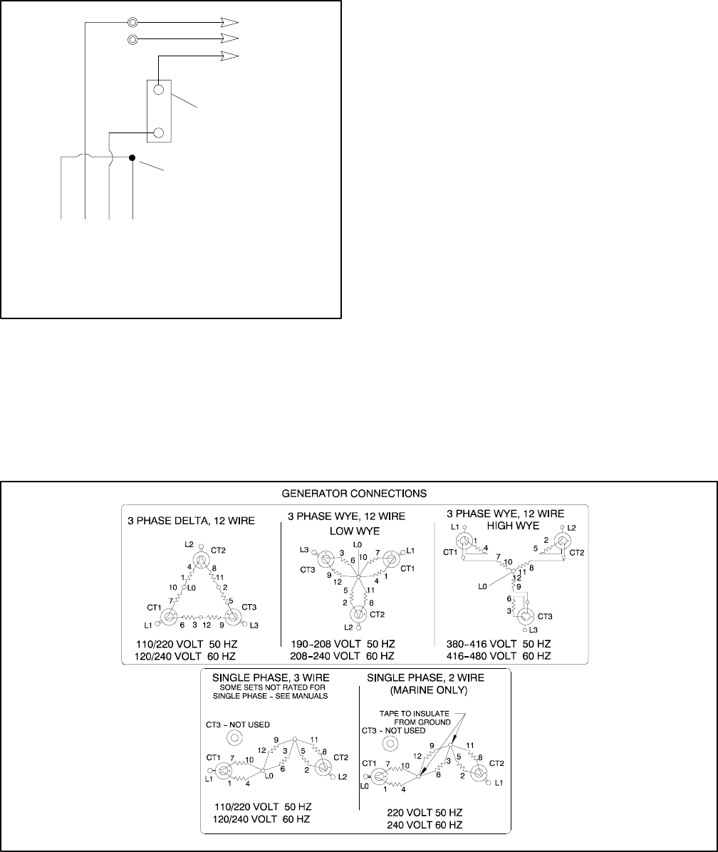
TP-6069 6/0368 Section 8 Reconnection/Adjustments
8.1.3 200--240-Volt Configurations
The 200--240-volt configuration does not use a jumper
lead. If the unit was originally wired for straight 100--120
volt, 3-wire, remove the jumper lead (see Figure 8-1 for
location).
4321
Stator Leads
L0
GRD.
L1
L0 (Neutral)
Line
Side
Single-Pole
Circuit
Breaker
Ground
Load
Side
200--220--240 Volt
2 Wire
Tape to insulate
from ground
60 Hz
L0--L1 200-240 Volt 200--220--240 Volt
50 Hz
Figure 8-4 200--220--240-Volt, 2-Wire Configuration
8.2 Twelve-Lead Reconnection
The reconnection procedure details voltage
reconnections only. If the generator set requires
frequency changes, adjust the governor and voltage
regulator. See the generator set service manual for
information regarding frequency adjustment.
The following information illustrates the reconnection of
twelve-lead generator sets. In all cases, conform to the
National Electrical Code (NEC).
Reconnect the stator leads of the generator set to
change output phase or voltage. Refer to the following
procedure and connection schematics. Follow all safety
precautions at the front of this manual and in the text
during the reconnection procedure.
NOTICE
Voltage reconnection. Affix a notice to the generator set after
reconnecting the set to a voltage different from the voltage on
the nameplate. Order voltage reconnection decal 246242
from an authorized service distributor/dealer.
Twelve-Lead Reconnection Procedure
1. Place the generator start/stop switch in the STOP
position.
2. Disconnect generator set engine starting battery,
negative (--) lead first.
3. Disconnect power to battery charger, if equipped.
4. Use Figure 8-5 to determine the generator set
voltage configuration. Note the original voltage
and reconnect the generator set as needed. Route
leads through current transformers (CTs) and
connect the leads according to the diagram for the
desired phase and voltage.
EM-250000-E
Note: Current Transformers (CTs) are not used on all sets. CT dot or “HI” toward generator.
Figure 8-5 Generator Reconnection
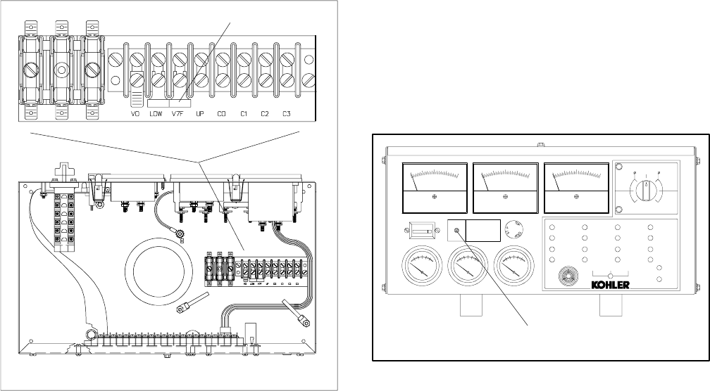
TP-6069 6/03 69Section 8 Reconnection/Adjustments
Note: Position the current transformers with the
dot or HI side CT marking toward the
generator set.
Note: Only generator sets equipped with AC meter
controllers and/or safeguard circuit
breakers require CTs.
5. If the controller has meters, remove the controller
cover and reposition the meter scale lamp jumper
(see Figure 8-6) matching the position of the
desired voltage (shown in Figure 8-5).
TP-5353-6
1
1. Lamp Jumper
Figure 8-6 Meter Scale Lamp Jumper
6. The overvoltage shutdown is standard on
Decision-Makert3+ controllers. The
139/240-volt (low wye) and 277/480-volt (high
wye), 3-phase, 4-wire, 60 Hz configurations use
different overvoltage shutdown settings than all
other configurations. Recalibrate the overvoltage
shutdown if the reconnection changes the voltage
to or from one of these configurations. See
Section 8.3, Decision-Maker 3+ Controller,
Overvoltage Shutdown Adjustment. Do not
recalibrate the overvoltage adjustment for other
voltage changes.
7. If the controller has meters, set the phase selector
switch to the L1-L2 position (1-phase or 3-phase
configuration depending on generator set
connection). Connect a voltmeter across leads L1
and L2 if the controller has no meters.
Note: Equipment damage. Verify that the voltage
ratings of the transfer switch, line circuit
breakers, and other accessories match the
desired line voltage.
8. Reconnect the starting battery, negative (--) lead
last. Place the generator set master switch in the
RUN position to start the generator set. Observe
the voltmeter and verify that the unit has the
desired line voltage connection.
Adjust the voltage using the voltage adjustment
potentiometer on the generator controller front
panel. See Figure 8-7.
9. Stop the generator set after completing the voltage
adjustment.
10. Disconnect the external voltmeter if used. Replace
the controller cover.
ADV-5849A-
1
1. Output voltage adjustment potentiometer
EMERGENCY
STOP
ONLY
OFF/RESET
PREALARM
HIGH ENGINE
TEMPERATURE
PREALARM
LOW OIL
PRESSURE
LOW WATER
TEMPERATURE
LOW FUEL
HIGH ENGINE
TEMPERATURE
LOW OIL
PRESSURE
EMERGENCY
STOP
OVERSPEED
AUXILIARY
FAULT
BATTERY
CHARGER FAULT
LOW BATTERY
VOLTAGE
OVERCRANK
AUXILIARY
PREALARM
AIR
DAMPER
SYSTEM
READY
GENERATOR
SWITCH
NOT IN AUTO
NORMALSILENCE
LAMP TEST
ALARM
AUTORUN
HERTZ A--C VOLTS A --C AMPERES
BATTERY
WATER
TEMP
OIL
PRESS
00000
TOTAL HOURS
LOWER METER SCALES
3
OFF
1
UPPER METER SCALES
AMPS
VOLTS
L0--L1
L3
L3--L1
L2
L1--L2 L1
L1--L2
L1
L1--L2 L2
L2--L3
S
VOLTAGE
ADJUST
O
Figure 8-7 Voltage Adjustment
This is bpid
8.3 Decision-Maker 3+ Controller,
Overvoltage Shutdown
Adjustment
Disconnecting the electrical load. Hazardous voltage can
cause severe injury or death. Disconnect the generator set
from the load by opening the line circuit breaker or by
disconnecting the generator set output leads from the transfer
switch and heavily taping the ends of the leads. High voltage
transferred to the load during testing may cause personal
injury and equipment damage. Do not use the safeguard
circuit breaker in place of the line circuit breaker. The
safeguard circuit breaker does not disconnect the generator
set from the load.
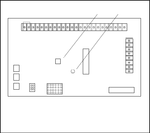
TP-6069 6/0370 Section 8 Reconnection/Adjustments
Short circuits. Hazardous voltage/current can cause
severe injury or death. Short circuits can cause bodily injury
and/or equipment damage.Do not contact electrical
connections with tools or jewelry while making adjustments or
repairs. Remove all jewelry before servicing the equipment.
Overvoltage Shutdown Adjustment Procedure
1. Disconnect the generator set engine starting
battery, negative (--) lead first. Disconnect power to
the battery charger (if equipped).
2. With the generator set shut down, open the output
line circuit breaker to disconnect the load from the
generator set.
3. Remove the controller cover.
4. Wrap the shaft of an insulated-handle screwdriver
with electrical tape to insulate the metal shaft. Turn
the overvoltage potentiometer (R41) on the main
circuit board fully clockwise. See Figure 8-8.
5. Connect a digital AC voltmeter (or other 1%
minimum accuracy voltmeter) to terminals V0 and
V7 on the controller terminal block. See
Figure 8-6.
6. Reconnect the battery, negative (--) lead last.
7. Start the generator set by placing the generator set
master switch in the RUN position.
8. Adjust the output voltage to 115% of the nominal
output voltage using the voltage adjustment
potentiometer. If the voltage configuration is
139/240 volts (low wye) or 277/480 volts (high
wye), 3-phase, 4-wire, 60 Hz, adjust output voltage
to 160 volts across terminals V0 and V7. For all
other voltages, adjust the output to 140 volts
across terminals V0 and V7.
Adjust the voltage using the voltage adjustment
potentiometer on the generator controller front
panel. See Figure 8-7.
9. Use the insulated screwdriver to slowly rotate the
overvoltage adjustment potentiometer (R41)
counterclockwise until red LED4 lights. See
Figure 8-8. The generator set should shut down on
an overvoltage fault in approximately 2 seconds.
P1
P2
A-336415-A
2
R41
LED4
1. Overvoltage adjustment potentiometer (R41)
2. LED4 (red)
1
Figure 8-8 Overvoltage Shutdown Adjustment on
Main Circuit Board
10. Turn the voltage adjustment potentiometer
counterclockwise to prevent overvoltage shutdown
upon restart. Restart the generator set. Slowly
increase the voltage by turning the voltage
adjustment potentiometer clockwise. Verify the
shutdown voltage point (115% of the nominal
output voltage) by observing the voltmeter and
noting when LED4 lights. The generator set should
shut down on overvoltage fault in approximately
2 seconds. If the shutdown voltage point is not
115% of nominal voltage, repeat the calibration
output procedure; otherwise, continue to step 11.
11. Turn the voltage adjustment potentiometer
counterclockwise to prevent overvoltage shutdown
upon restart. Restart the generator set. Readjust
the generator set output to the nominal voltage
using the voltage adjustment potentiometer.
12. Stop the generator set by placing the generator set
master switch in the OFF/RESET position. Seal
the overvoltage adjustment potentiometer (R41)
with RTV sealant or equivalent. Replace the
controller cover.
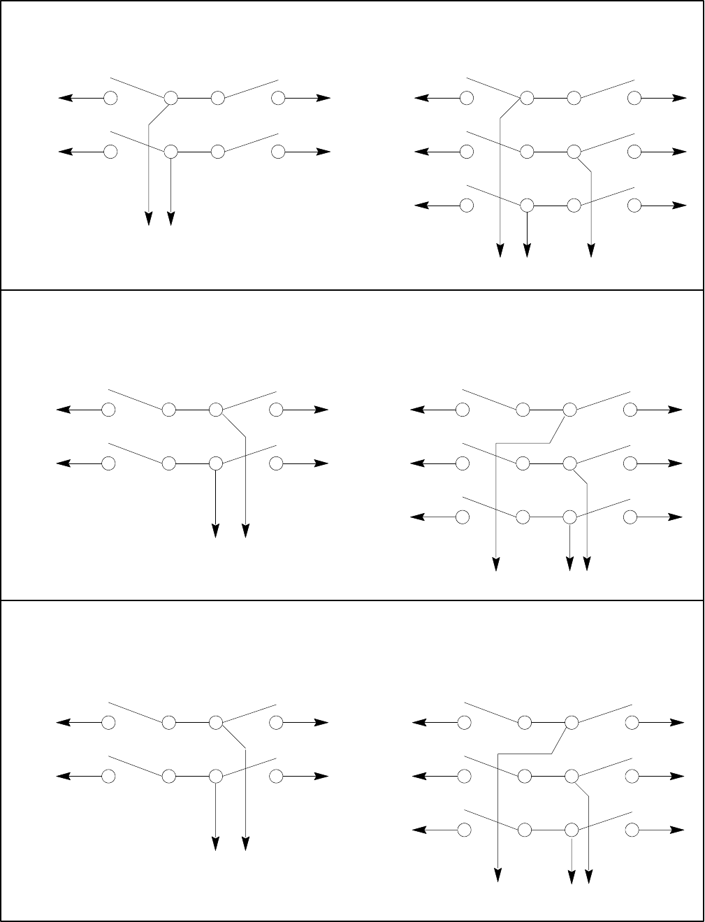
TP-6069 6/03 71Section 8 Reconnection/Adjustments
Electroswitch
L1
L2
To Generator
Set
To Shore
Power
To Load
2-Wire Generator Sets
L1
L2
To Generator
Set
To Shore
Power
To Load
2-Wire Generator Sets
2-Wire Generator Sets
Kraus Naimler/American Solenoid
(Early Rectangular Design)
Kraus Naimler/American Solenoid
(Newer Round Design)
2134
6578
1265
348 7
L1
L2
To Generator
Set
To Shore
Power
To Load
3241
768 5
L1
L2
To Generator
Set
To Shore
Power
To Load
3-Wire Generator Sets
2134
657 8
L0
10 9 11 12
1265
348 7
91014 13
L1
L2
To Generator
Set
To Shore
Power
To Load
3-Wire Generator Sets
L0
3241
768 5
11 10 12 9
L1
L2
To Generator
Set
To Shore
Power
To Load
3-Wire Generator Sets
L0
TP-5399-5
Figure 8-9 Marine Manual (Ship-to-Shore) Transfer Switch
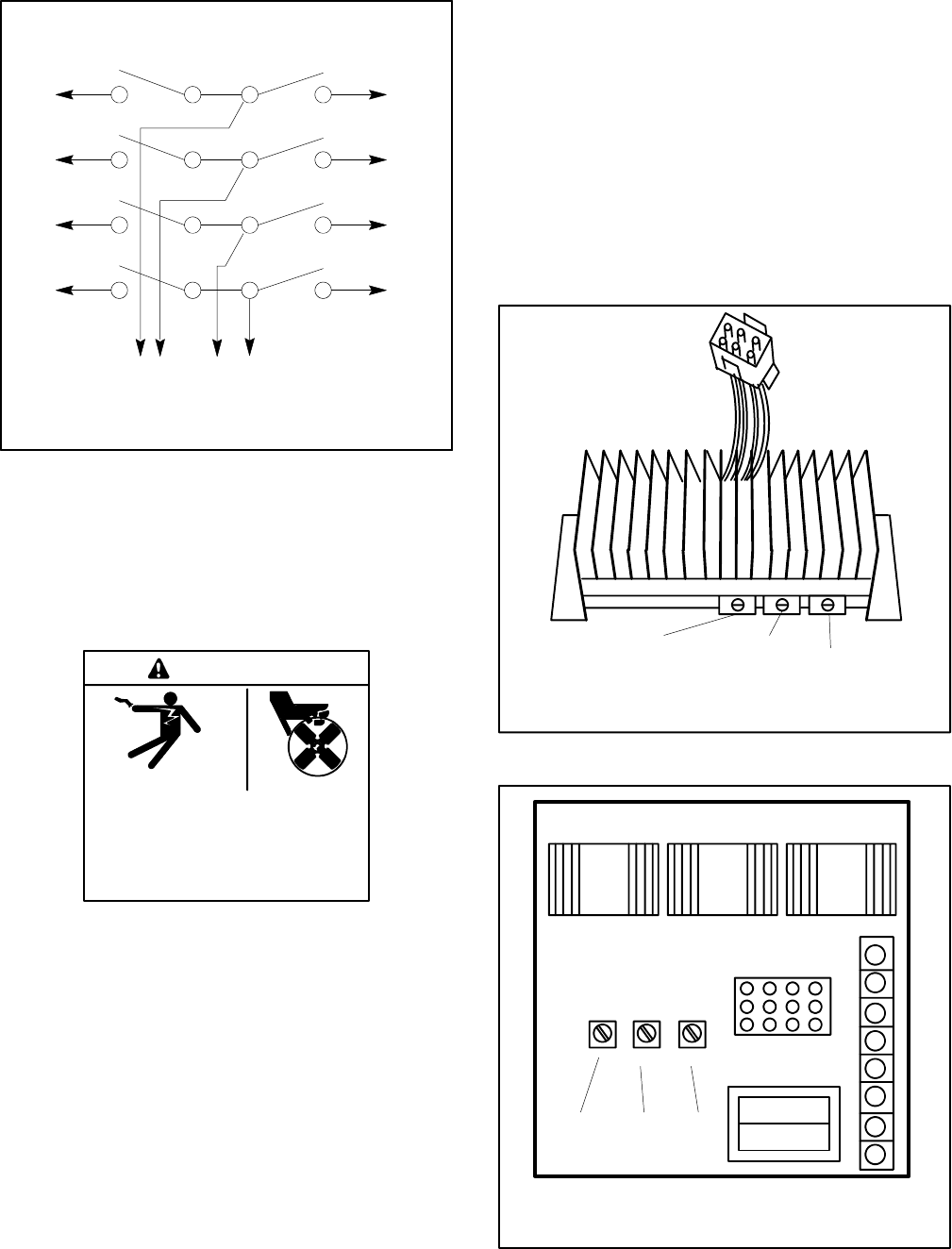
TP-6069 6/0372 Section 8 Reconnection/Adjustments
7685
11 10 12 9
15 14 16 13
L2
L3
To Generator
Set
To Shore
Power
To Load
4-Wire, 3-Phase Generator Sets
L0
3241
L1
L2
L3
L0
L1
L2 L3 L0L1
Kraus Naimler/American Solenoid
I-940
Figure 8-10 Marine Manual (Ship-to-Shore) Transfer
Switch, continued
8.4 Voltage Regulator Adjustment
(4--27EFOZ and 5--32EOZ
Models)
Hazardous voltage.
Can cause severe injury or death.
Operate the generator set only when
all guards and electrical enclosures
areinplace.
Moving rotor.
WARNING
Testing the voltage regulator. Hazardous voltage can
cause severe injury or death. High voltage is present at the
voltage regulator heat sink. To prevent electrical shock do not
touch the voltage regulator heat sink when testing the voltage
regulator.
(PowerBoostt, PowerBoosttIII, and PowerBoosttV
voltage regulator models only)
The voltage regulator is typically located in the
controller. Adjustments are possible without removing
the voltage regulator. The voltage regulator adjustment
procedure applies to both the PowerBoostIIIE
(Figure 8-11) and PowerBoostV (Figure 8-12) voltage
regulators.
Note: Broadrange generator sets. The following
adjustment procedure is for readjustment of the
voltage regulator and governor for broadrange
generator sets with mechanical governors.
Note: Special tool. Frequency meter 50/60 Hz.
Note: Rheostat connection. Connect a
customer-provided rheostat across regulator
leads/terminals 33 and 66 to adjust the generator
output voltage from a location remote from the
generator set. The rheostat (10 kOhms, 1/2 watt
minimum) provides a 5-volt adjustment range.
TT-875-11
123
1. Voltage adjustment potentiometer
2. Stability adjustment potentiometer
3. Volts/Hz adjustment potentiometer
Figure 8-11 PowerBoostIIIE Voltage Regulator
8
7
6
5
4
3
2
1
VOLTSV/HZ
STAB
TT-875-11
231
1. Voltage adjustment potentiometer
2. Stability adjustment potentiometer
3. Volts/Hz adjustment potentiometer
Figure 8-12 PowerBoostV Voltage Regulator
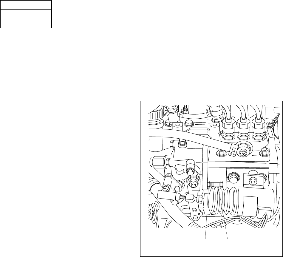
TP-6069 6/03 73Section 8 Reconnection/Adjustments
Stabilizer Potentiometer (Pot) fine tunes the regulator
circuitry to reduce light flicker.
Voltage Adjustment Pot adjusts the generator voltage
output within the range of approximately 100 to 130
volts.
Volts/Hz Pot determines the engine speed (Hz) at
which the generator output voltage begins to drop.
Note: The volts/Hz adjustment does not apply to the
following models:
Model
4/6.5/8/8.5/9EFOZ
5/8/9/10EOZ
Note: On these models, turn the volts/Hz adjustment
pot full counterclockwise to stop and seal. No
further volts/Hz adjustments are required.
Note: For optimum results, apply full load for voltage
regulator adjustment.
Voltage Regulator Adjustment Procedure
1. With the generator set off, turn the remote
rheostat, if equipped, to the midpoint.
2. Turn the voltage, volts/Hz, and stability pots fully
counterclockwise.
3. Connect the voltmeter and frequency meter to the
AC circuit or an electrical outlet.
4. Start the generator set.
5. Rotate the voltage adjustment pot clockwise to
increase the voltage (counterclockwise to
decrease voltage) to achieve the desired output
voltage.
6. Rotate the stability pot clockwise to minimize light
flicker.
7. Readjust the voltage adjustment pot if necessary.
8. Adjust the engine speed to the desired cut-in
frequency (factory setting 57.5–58 Hz for 60 Hz
models or 47.5–48 Hz for 50 Hz models) as
measured on frequency meter. To change engine
speed adjust the governor arm. Loosen the
locknut and turn it clockwise or counterclockwise
to achieve the desired frequency. See
Figure 8-13. If a second screw holds the governor
arm, loosen the locknut and back out the screw.
9. If applicable, rotate the volts/Hz adjustment pot
clockwise until the voltage level begins to drop (as
measured on the voltmeter). When set to these
specifications, the generator attempts to maintain
normal output until the engine speed drops below
the frequency set in step 8 as load is applied.
10. Readjust the engine speed to normal (63 Hz/
1890 rpm for 60 Hz or 52.5 Hz/1575 rpm for
50 Hz). Tighten the locknut when the adjustments
are complete. Turn the second screw, if used, to
lock the governor arm in place and tighten the
locknut.
11. Readjust the voltage adjustment pot if necessary.
12. Readjust the stability pot if necessary.
13. Use the remote rheostat, if equipped, to make final
voltage adjustments.
14. Stop the generator set.
1-929
1 2
1. Locknut
2. Speed adjusting screw
Figure 8-13 Governor Adjustment (4EFOZ/5EOZ
shown)
TP-6069 6/0374 Section 8 Reconnection/Adjustments
Notes
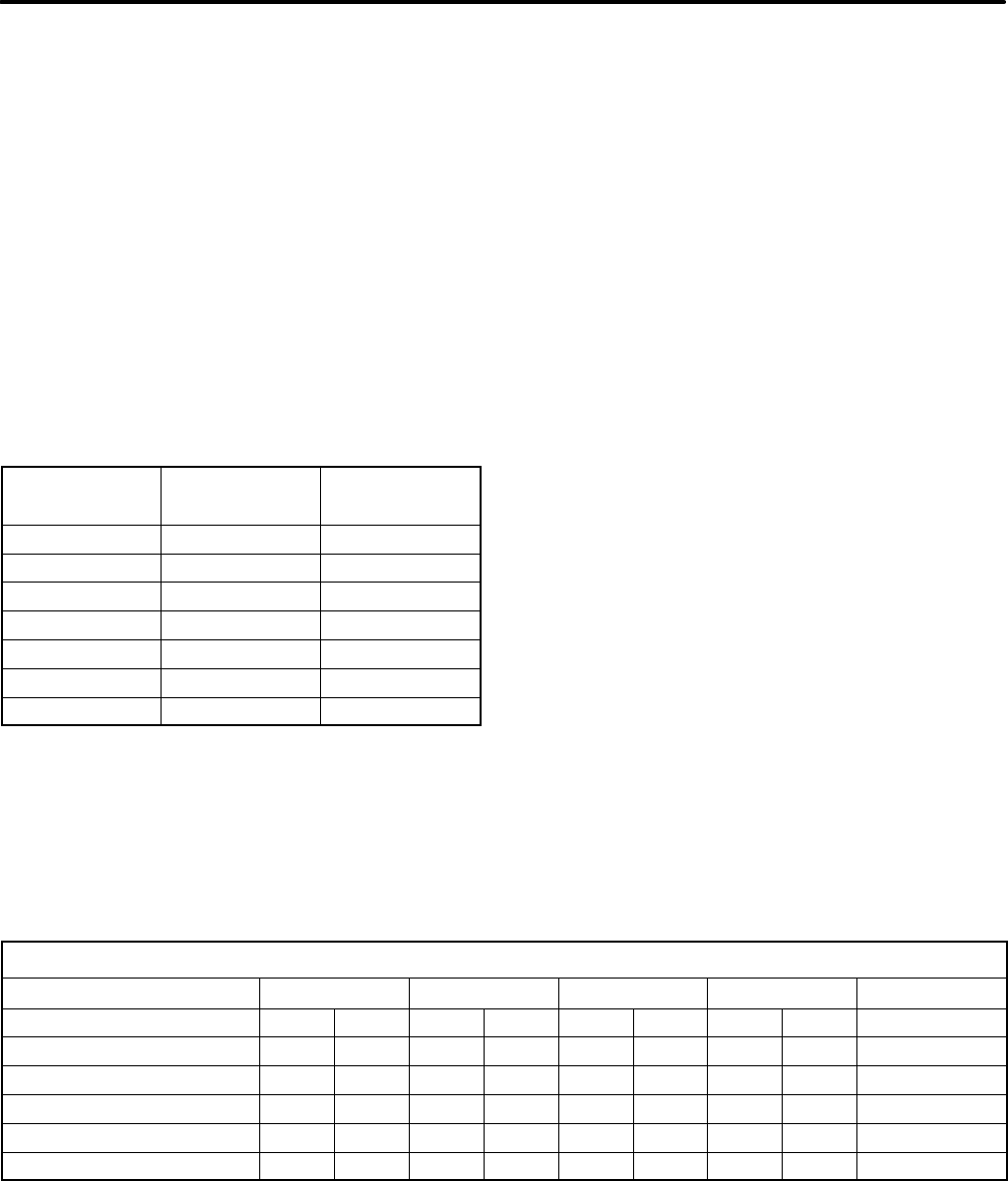
TP-6069 6/03 A-1Appendix
Appendix A Generator Selection and Wattage Requirements
Consider total wattage requirements (lights, motors,
appliances) when selecting a generator set or when
sizing wattage usage in which available space and
construction limit the size of the generator set.
Motors
When figuring generator set capacity requirements for
loads that include electric motors, consider the high
current demanded by the motors during startup. The
inrush or starting current is typically 2--3 times higher
than that required when the motor reaches normal
operating speed. Allow reserve for inrush demands plus
other loads which could be on the line as the electric
motor starts. Use Figure 1 as a guide when selecting
generator set capacity requirements involving motor
loads.
Motor
HP
Starting (Inrush)
Watts
Running
Watts
1/4 750 330
1/3 1000 400
1/2 1500 600
3/4 2000 750
13300 1100
24000 2000
35000 3000
Figure 1 Motor Requirements
Lighting
To calculate lighting load, add the wattage of each
generator set-operated lamp. Note that not all of the
lights or lamps are on the generator set AC circuit; some
are DC powered by a 12-volt battery. Make sure the
calculated total wattage includes only lights actually on
the generator set AC circuit.
Air Conditioners
The starting characteristics of air conditioners vary
greatly; one 12,000 Btu unit has, for example, lower
starting requirements than a 10,000 Btu unit of another
variety. When using only one unit, there is usually no
starting problem, provided the lighting and appliance
load is not too high when starting the unit.
Simultaneous starting of two air conditioning units,
however, can present problems if the generator set
capacity is marginal. Because of the variation in starting
characteristics among air conditioners, this publication
makes no statements regarding multiple-motor starting
capabilities of the generator set covered. Consider
delayed starting or use of easy-starting devices on air
conditioner units whenever simultaneously starting
more than one motor.
See Figure 2 for typical air conditioner requirements.
Information will vary with manufacturer.
Appliances
Generator sets often furnish AC for appliances such as
TV, stereo, electric water heater, etc. With the exception
of the resistance-type loads such as the water heater,
requirements for appliances are usually low. Do not
overlook such loads when figuring total requirements.
Allow reserve capacity for anticipated appliance loads to
avoid overloading a generator set.
Air Conditioner Size (Btu/Hr.)
7,000 9,000 12,000 16,000 24,000
Voltage 115 230 115 230 115 230 115 230 230
Full load amps 9.3 4.8 9.9 5.0 11.8 6.3 16.3 8.0 11.6
Rated load amps 7.7 4.0 7.0 3.5 8.9 4.8 13.0 6.2 10.2
Locked rotor amps 34.0 20.0 40.0 20.0 50.0 31.0 75.0 36.0 56.0
Starting (inrush) watts 3910 4600 4600 4600 5750 7130 8630 8280 12,900
Running watts 886 920 805 805 1020 1100 1500 1430 2350
Figure 2 Typical Marine Air Conditioner Requirements, 60 Hz

TP-6069 6/03A-2 Appendix
Appendix B Abbreviations
The following list contains abbreviations that may appear in this publication.
A, amp ampere
ABDC after bottom dead center
AC alternating current
A/D analog to digital
ADC analog to digital converter
adj. adjust, adjustment
ADV advertising dimensional
drawing
AHWT anticipatory high water
temperature
AISI American Iron and Steel
Institute
ALOP anticipatory low oil pressure
alt. alternator
Al aluminum
ANSI American National Standards
Institute
(formerly American Standards
Association, ASA)
AO anticipatory only
API American Petroleum Institute
approx. approximate, approximately
AR as required, as requested
AS as supplied, as stated, as
suggested
ASE American Society of Engineers
ASME American Society of
Mechanical Engineers
assy. assembly
ASTM American Society for Testing
Materials
ATDC after top dead center
ATS automatic transfer switch
auto. automatic
aux. auxiliary
A/V audiovisual
avg. average
AVR automatic voltage regulator
AWG American Wire Gauge
AWM appliance wiring material
bat. battery
BBDC before bottom dead center
BC battery charger, battery
charging
BCA battery charging alternator
BCI Battery Council International
BDC before dead center
BHP brake horsepower
blk. black (paint color), block
(engine)
blk. htr. block heater
BMEP brake mean effective pressure
bps bits per second
br. brass
BTDC before top dead center
Btu British thermal unit
Btu/min. British thermal units per minute
C Celsius, centigrade
cal. calorie
CARB California Air Resources Board
CB circuit breaker
cc cubic centimeter
CCA cold cranking amps
ccw. counterclockwise
CEC Canadian Electrical Code
cfh cubic feet per hour
cfm cubic feet per minute
CG center of gravity
CID cubic inch displacement
CL centerline
cm centimeter
CMOS complementary metal oxide
substrate (semiconductor)
cogen. cogeneration
Com communications (port)
conn. connection
cont. continued
CPVC chlorinated polyvinyl chloride
crit. critical
CRT cathode ray tube
CSA Canadian Standards
Association
CT current transformer
Cu copper
cu. in. cubic inch
cw. clockwise
CWC city water-cooled
cyl. cylinder
D/A digital to analog
DAC digital to analog converter
dB decibel
dBA decibel (A weighted)
DC direct current
DCR direct current resistance
deg., °degree
dept. department
dia. diameter
DI/EO dual inlet/end outlet
DIN Deutsches Institut fur Normung
e. V.
(also Deutsche Industrie
Normenausschuss)
DIP dual inline package
DPDT double-pole, double-throw
DPST double-pole, single-throw
DS disconnect switch
DVR digital voltage regulator
E, emer. emergency (power source)
EDI electronic data interchange
EFR emergency frequency relay
e.g. for example (exempli gratia)
EG electronic governor
EGSA Electrical Generating Systems
Association
EIA Electronic Industries
Association
EI/EO end inlet/end outlet
EMI electromagnetic interference
emiss. emission
eng. engine
EPA Environmental Protection
Agency
EPS emergency power system
ER emergency relay
ES engineering special,
engineered special
ESD electrostatic discharge
est. estimated
E-Stop emergency stop
etc. et cetera (and so forth)
exh. exhaust
ext. external
F Fahrenheit, female
fglass. fiberglass
FHM flat head machine (screw)
fl. oz. fluid ounce
flex. flexible
freq. frequency
FS full scale
ft. foot, feet
ft. lbs. foot pounds (torque)
ft./min. feet per minute
ggram
ga. gauge (meters, wire size)
gal. gallon
gen. generator
genset generator set
GFI ground fault interrupter
GND, ground
gov. governor
gph gallons per hour
gpm gallons per minute
gr. grade, gross
GRD equipment ground
gr. wt. gross weight
H x W x D height by width by depth
HC hex cap
HCHT high cylinder head temperature
HD heavy duty
HET high exhaust temperature
hex hexagon
Hg mercury (element)
HH hex head
HHC hex head cap
HP horsepower
hr. hour
HS heat shrink
hsg. housing
HVAC heating, ventilation, and air
conditioning
HWT high water temperature
Hz hertz (cycles per second)
IC integrated circuit
ID inside diameter, identification
IEC International Electrotechnical
Commission
IEEE Institute of Electrical and
Electronics Engineers
IMS improved motor starting
in. inch
in. H2O inches of water
in. Hg inches of mercury
in. lbs. inch pounds
Inc. incorporated
ind. industrial
int. internal
int./ext. internal/external
I/O input/output
IP iron pipe
ISO International Organization for
Standardization
J joule
JIS Japanese Industry Standard
k kilo (1000)
K kelvin
kA kiloampere
KB kilobyte (210 bytes)
TP-6069 6/03 Appendix A-3
kg kilogram
kg/cm2kilograms per square
centimeter
kgm kilogram-meter
kg/m3kilograms per cubic meter
kHz kilohertz
kJ kilojoule
km kilometer
kOhm, kΩkilo-ohm
kPa kilopascal
kph kilometers per hour
kV kilovolt
kVA kilovolt ampere
kVAR kilovolt ampere reactive
kW kilowatt
kWh kilowatt-hour
kWm kilowatt mechanical
L liter
LAN local area network
L x W x H length by width by height
lb. pound, pounds
lbm/ft3pounds mass per cubic feet
LCB line circuit breaker
LCD liquid crystal display
ld. shd. load shed
LED light emitting diode
Lph liters per hour
Lpm liters per minute
LOP low oil pressure
LP liquefied petroleum
LPG liquefied petroleum gas
LS left side
Lwa sound power level, A weighted
LWL low water level
LWT low water temperature
m meter, milli (1/1000)
M mega (106when used with SI
units), male
m3cubic meter
m3/min. cubic meters per minute
mA milliampere
man. manual
max. maximum
MB megabyte (220 bytes)
MCM one thousand circular mils
MCCB molded-case circuit breaker
meggar megohmmeter
MHz megahertz
mi. mile
mil one one-thousandth of an inch
min. minimum, minute
misc. miscellaneous
MJ megajoule
mJ millijoule
mm millimeter
mOhm, mΩ
milliohm
MOhm, MΩ
megohm
MOV metal oxide varistor
MPa megapascal
mpg miles per gallon
mph miles per hour
MS military standard
m/sec. meters per second
MTBF mean time between failure
MTBO mean time between overhauls
mtg. mounting
MW megawatt
mW milliwatt
µF microfarad
N, norm. normal (power source)
NA not available, not applicable
nat. gas natural gas
NBS National Bureau of Standards
NC normally closed
NEC National Electrical Code
NEMA National Electrical
Manufacturers Association
NFPA National Fire Protection
Association
Nm newton meter
NO normally open
no., nos. number, numbers
NPS National Pipe, Straight
NPSC National Pipe, Straight-coupling
NPT National Standard taper pipe
thread per general use
NPTF National Pipe, Taper-Fine
NR not required, normal relay
ns nanosecond
OC overcrank
OD outside diameter
OEM original equipment
manufacturer
OF overfrequency
opt. option, optional
OS oversize, overspeed
OSHA Occupational Safety and Health
Administration
OV overvoltage
oz. ounce
p., pp. page, pages
PC personal computer
PCB printed circuit board
pF picofarad
PF power factor
ph., ∅phase
PHC Phillips head crimptite (screw)
PHH Phillips hex head (screw)
PHM pan head machine (screw)
PLC programmable logic control
PMG permanent-magnet generator
pot potentiometer, potential
ppm parts per million
PROM programmable read-only
memory
psi pounds per square inch
pt. pint
PTC positive temperature coefficient
PTO power takeoff
PVC polyvinyl chloride
qt. quart
qty. quantity
R replacement (emergency)
power source
rad. radiator, radius
RAM random access memory
RDO relay driver output
ref. reference
rem. remote
RFI radio frequency interference
RH round head
RHM round head machine (screw)
rly. relay
rms root mean square
rnd. round
ROM read only memory
rot. rotate, rotating
rpm revolutions per minute
RS right side
RTV room temperature vulcanization
SAE Society of Automotive
Engineers
scfm standard cubic feet per minute
SCR silicon controlled rectifier
s, sec. second
SI Systeme international d’unites,
International System of Units
SI/EO side in/end out
sil. silencer
SN serial number
SPDT single--pole, double--throw
SPST single--pole, single--throw
spec, specs
specification(s)
sq. square
sq. cm square centimeter
sq. in. square inch
SS stainless steel
std. standard
stl. steel
tach. tachometer
TD time delay
TDC top dead center
TDEC time delay engine cooldown
TDEN time delay emergency to
normal
TDES time delay engine start
TDNE time delay normal to
emergency
TDOE time delay off to emergency
TDON time delay off to normal
temp. temperature
term. terminal
TIF telephone influence factor
TIR total indicator reading
tol. tolerance
turbo. turbocharger
typ. typical (same in multiple
locations)
UF underfrequency
UHF ultrahigh frequency
UL Underwriter’s Laboratories, Inc.
UNC unified coarse thread (was NC)
UNF unified fine thread (was NF)
univ. universal
US undersize, underspeed
UV ultraviolet, undervoltage
V volt
VAC volts alternating current
VAR voltampere reactive
VDC volts direct current
VFD vacuum fluorescent display
VGA video graphics adapter
VHF very high frequency
W watt
WCR withstand and closing rating
w/ with
w/o without
wt. weight
xfmr transformer
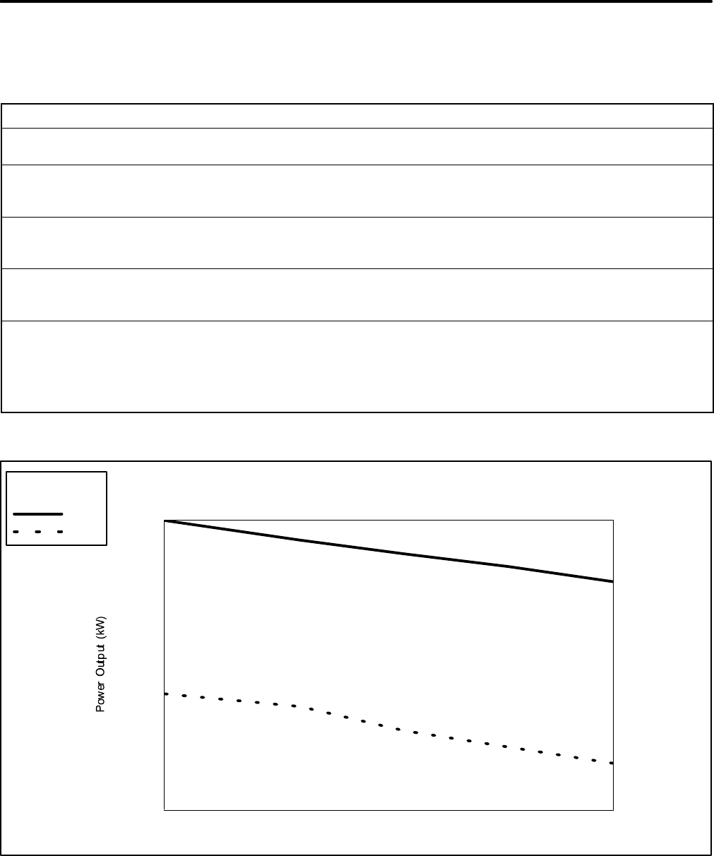
TP-6069 6/03A-4 Appendix
Appendix C Generator Set Output Ratings Procedure
Kohler Co. develops the kilowatt output rating of a Kohlerr
marine generator set based upon the calculations
specified in ISO 3046 and ISO 8528-1. The calculations
correct for environmental variables encountered in a
generator set installation. Figure 1 outlines the
calculations. Figure 2 contains examples of how heat
variables affect generator set ratings.
Generator Output corrected = Generator Output observed x Correction Factor
Output power is expected to be within ±5% of the specified rating when corrected to reference conditions.
Correction factors are determined using the following formulas:
1. For naturally aspirated compression-ignition engines (power limited by excess air):
C.F. = [1.175 (29.2 / Dry Barometer in. Hg)1(Temperature _F + 460/537).75 -- .175]
x Alternator Efficiency Reference / Alternator Efficiency Observed
2. For turbocharged compression ignition engines:
C.F. = [1.175 (29.2 / Barometer Observed in. Hg).7 (Temperature _F + 460/537)2-- .175]
x Alternator Efficiency Reference / Alternator Efficiency Observed
3. For turbocharged and intercooled compression ignition engines:
C.F. = [1.175 (29.2 / Barometer Observed in. Hg).7 (Temperature _F + 460/537)1.2 -- .175]
x Alternator Efficiency Reference / Alternator Efficiency Observed
Reference conditions:
Temperature: 77_F; Pressure: 29.2 in. Hg dry barometer.
Kohler sound shield increases ambient intake air approx. 12_F
Approximate derates:
Temperature: approximately 1% per 10_F (turbocharged engines have a greater derate);
Pressure (altitude): approximately 4% per 1000 ft. (1 in. Hg)
Figure 1 Generator Output
5.5
5.6
5.7
5.8
5.9
6.0
6.1
6.2
6.3
6.4
6.5
6.6
6.7
6.8
6.9
7.0
7.1
7.2
7.3
7.4
7.5
7.6
7.7
7.8
7.9
8.0
75 80 85 90 95 100 105 110 115 120
Temperature (_F)
77
60 Hz
50 Hz
KEY
Figure 2 Example: 6.5EFOZ/8EOZ kW Derates (ISO 3046/ISO 8258-1)

E2000, 2001, 2002, and 2003 by Kohler Co. All rights reserved.
TP-6069 6/03d
KOHLER CO. Kohler, Wisconsin 53044
Phone 920-565-3381, Fax 920-459-1646
For the nearest sales/service outlet in the
US and Canada, phone 1-800-544-2444
KohlerPowerSystems.com
Kohler Power Systems
Asia Pacific Headquarters
7 Jurong Pier Road
Singapore 619159
Phone (65)264-6422, Fax (65)264-6455
