Kongsberg Seatex AS AIS Seatex AIS 100/Simrad AI 70 User Manual Seatex AIS 100 Instruction Manual
Kongsberg Seatex AS Seatex AIS 100/Simrad AI 70 Seatex AIS 100 Instruction Manual
UserManual.wiki
>
Kongsberg Seatex AS
>
AIS User Manual
Seatex AIS 100 Instruction Manual
Navigation menu
Upload a User Manual
Namespaces
Wiki Guide
HTML
PDF
Info
Views
User Manual
Discussion / Help
Navigation


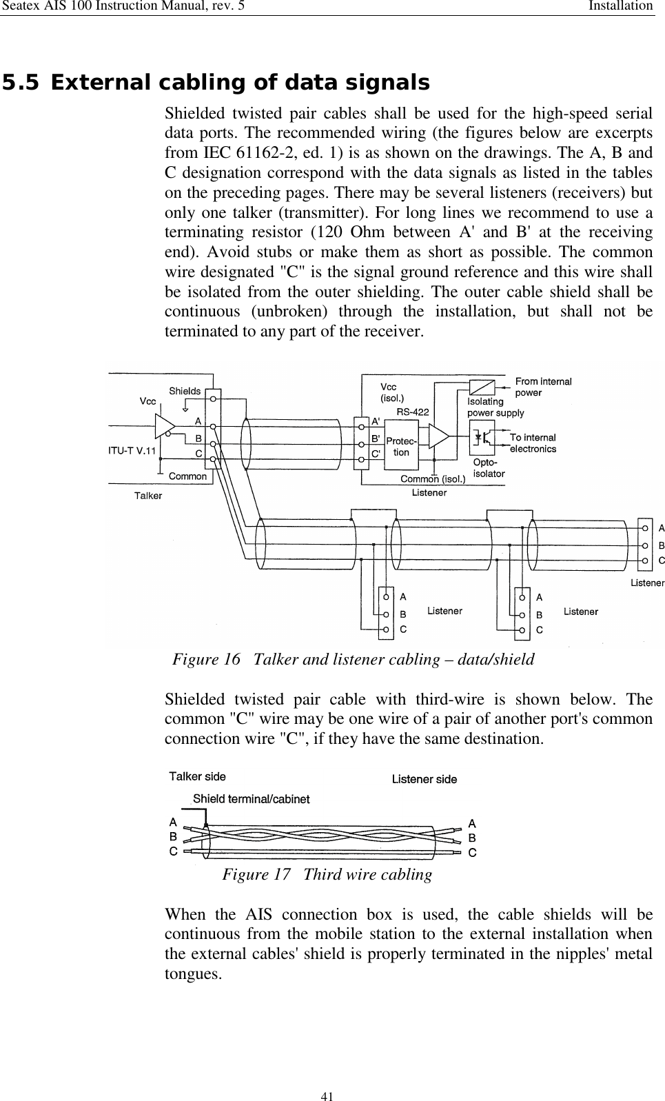
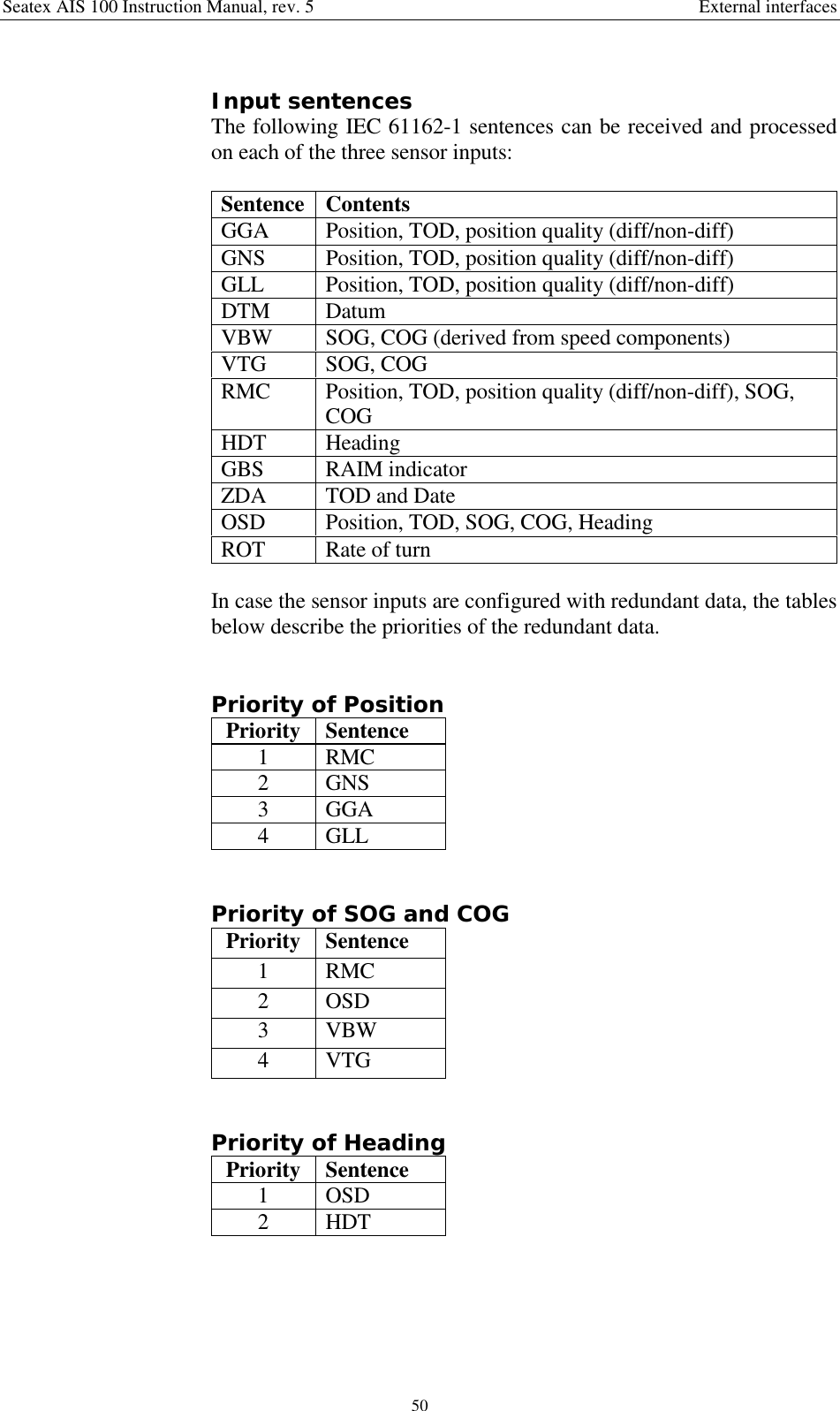
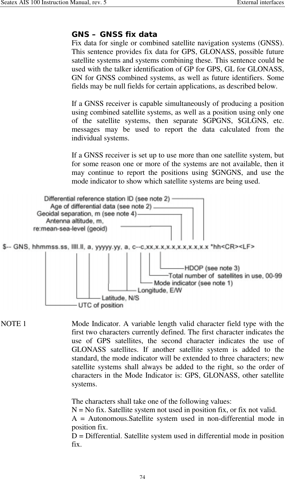
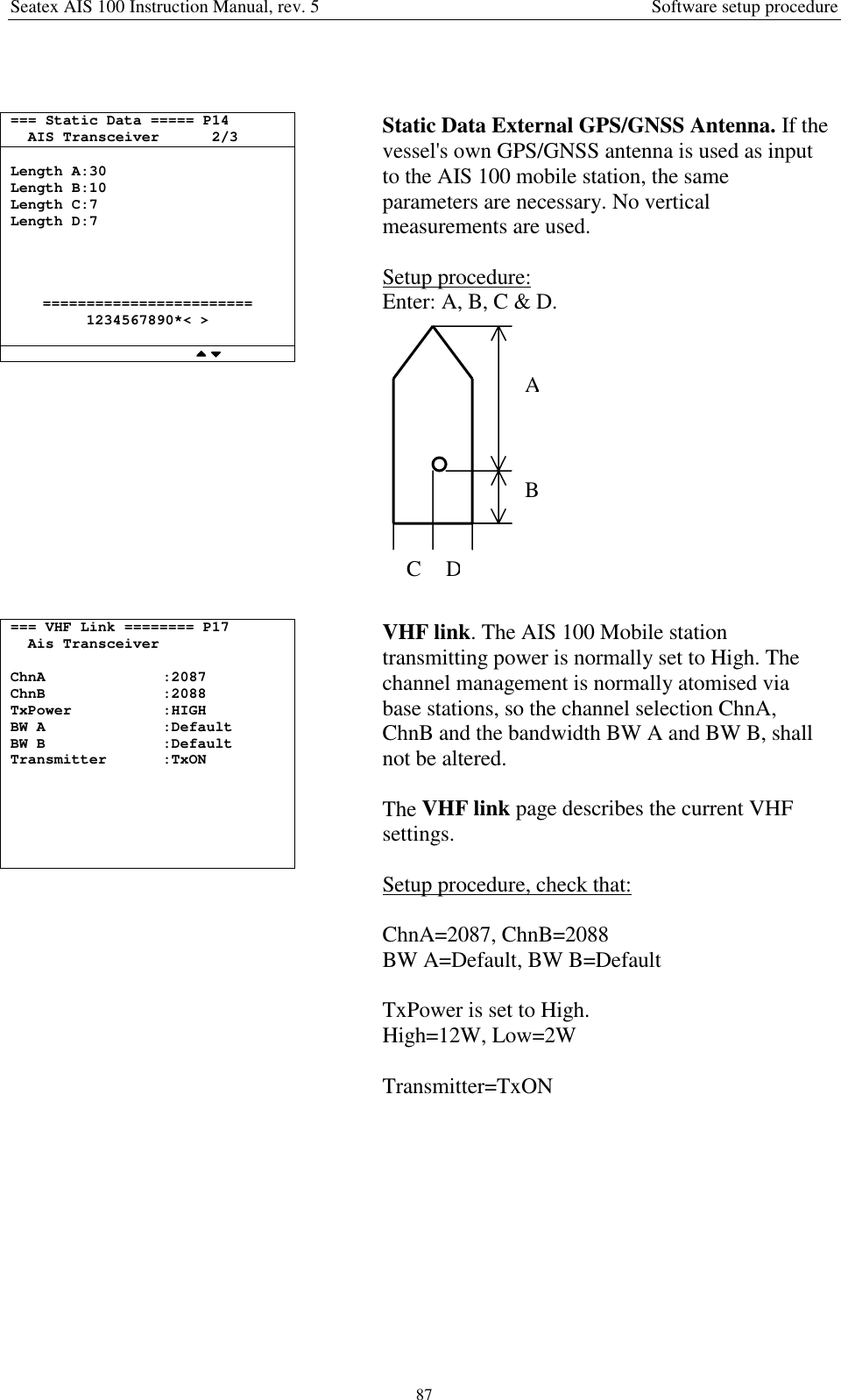
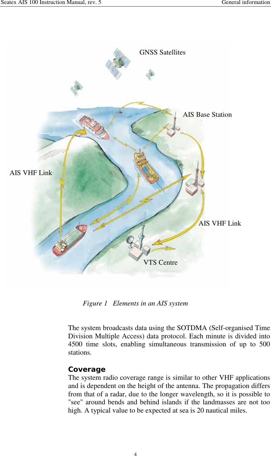
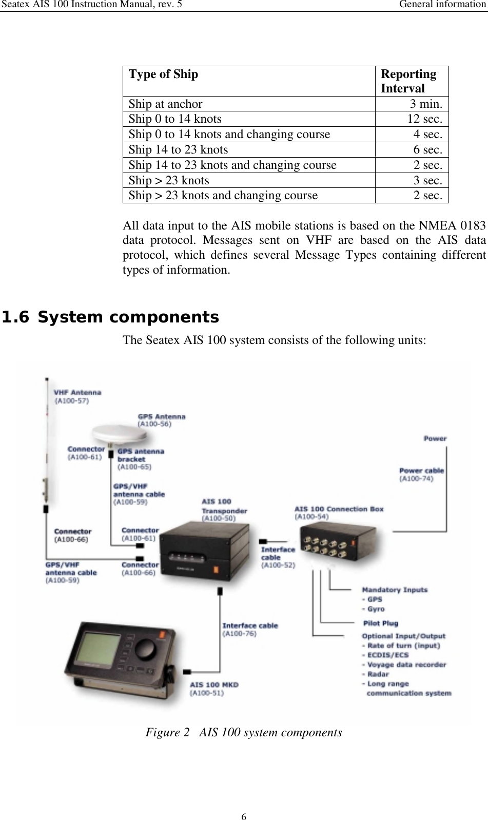
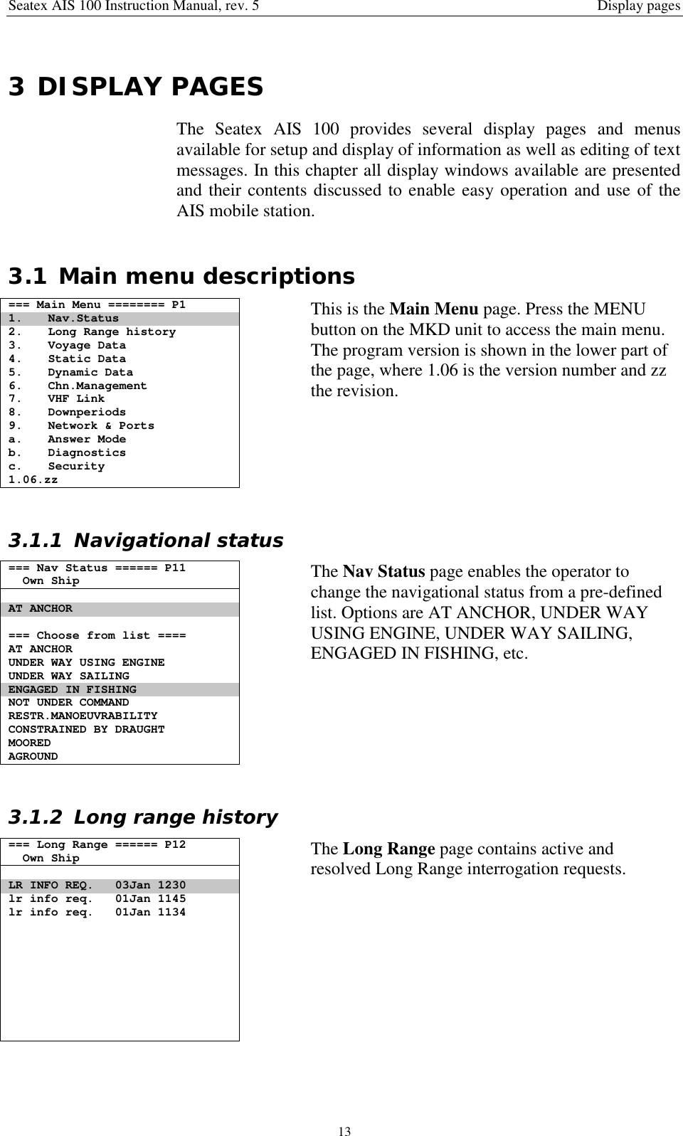
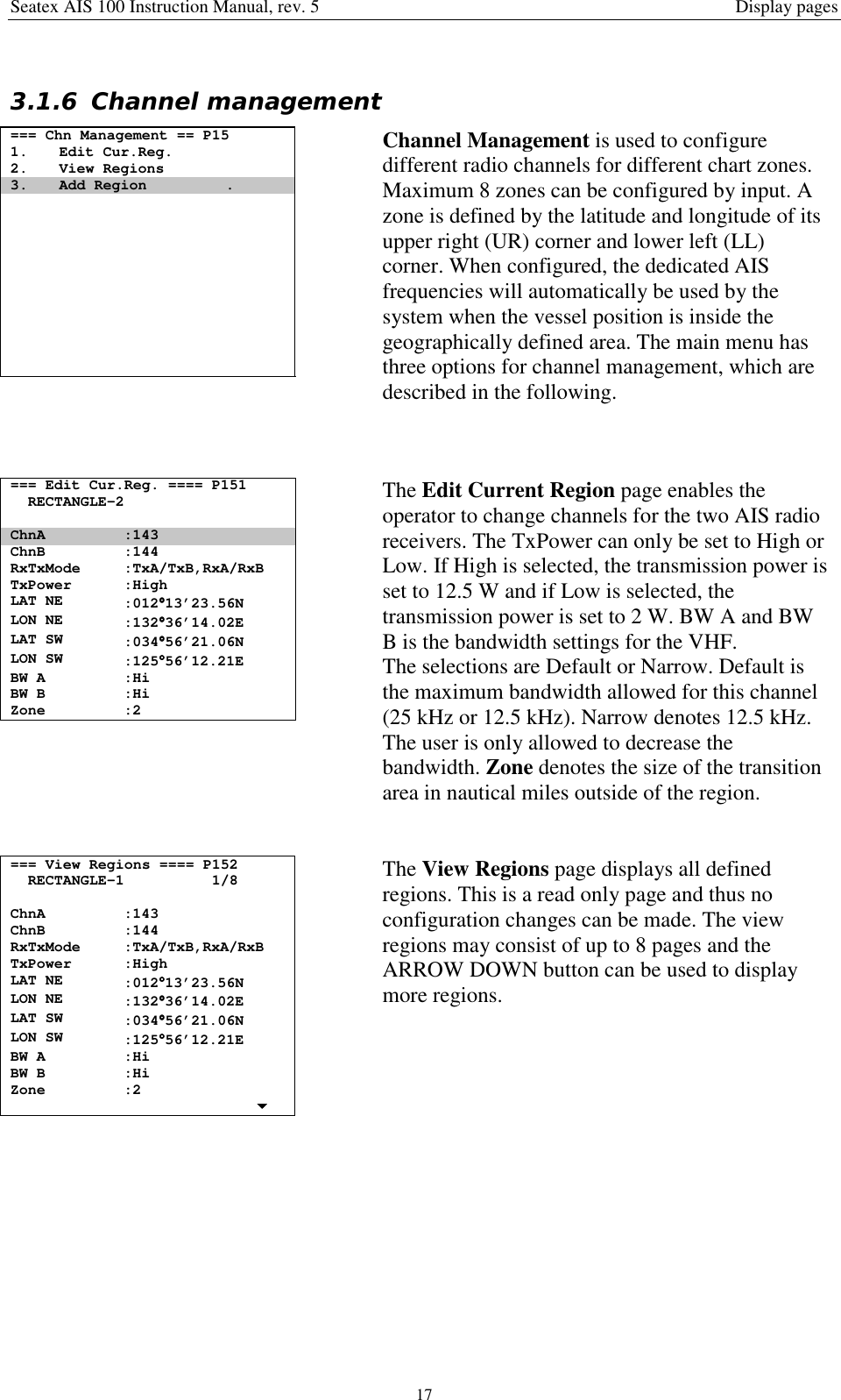
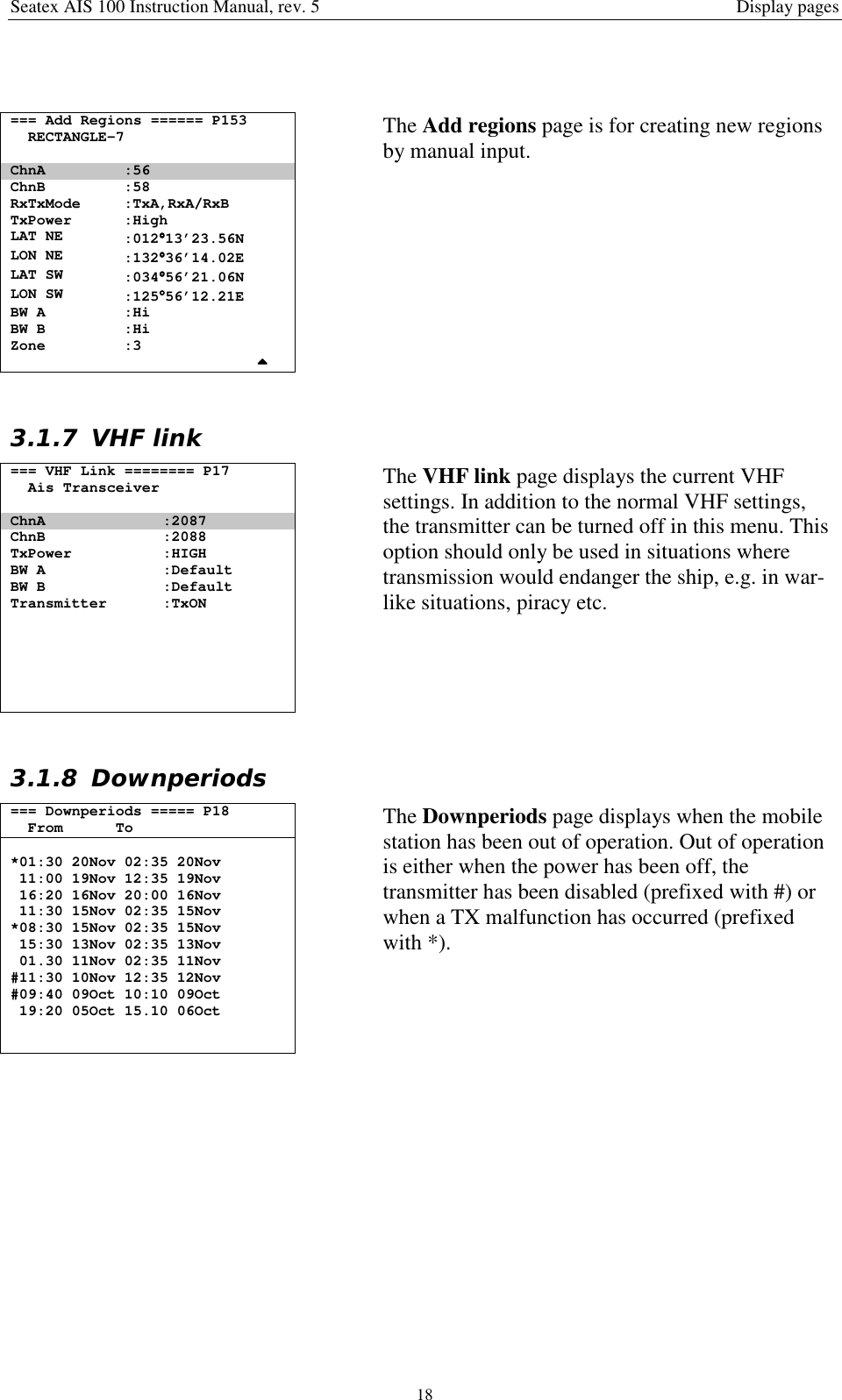
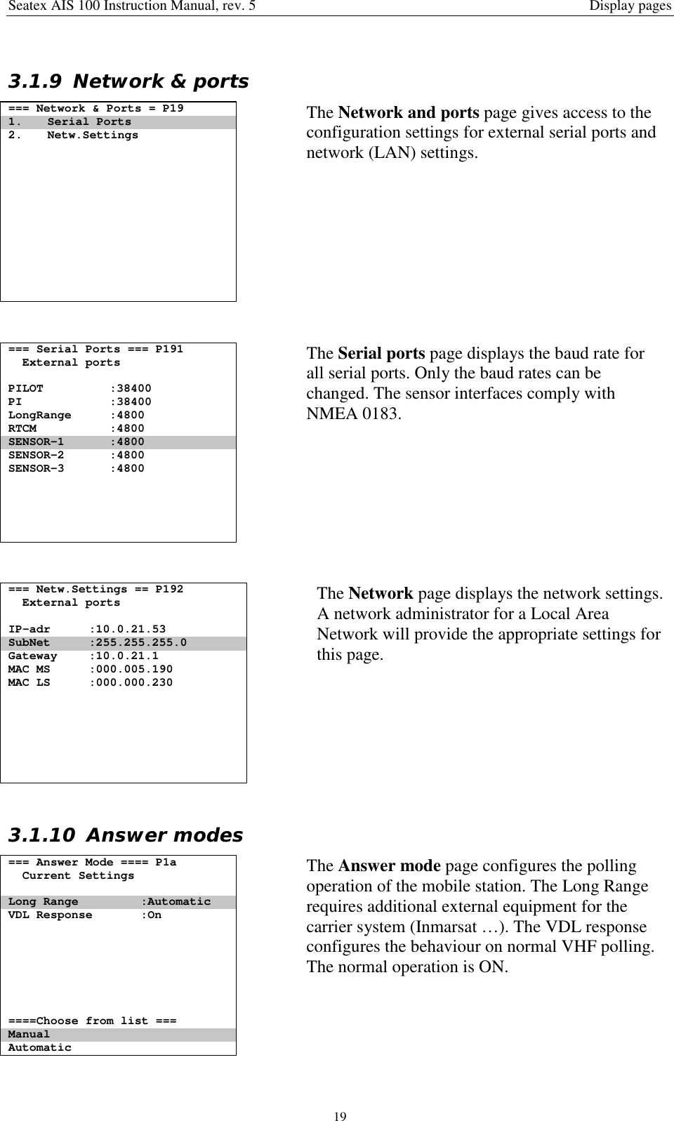
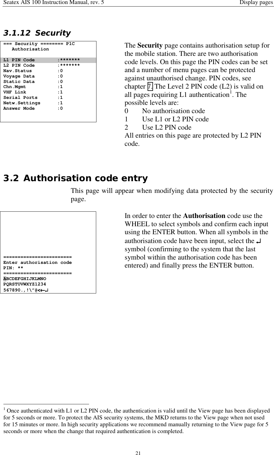
![Seatex AIS 100 Instruction Manual, rev. 5 General information11 GENERAL INFORMATION1.1 IntroductionCongratulations on the purchase of your new Seatex AIS 100 andthank you for selecting what is one of the best AIS systems availableon the market today.Kongsberg Seatex AS manufactures several positioning andnavigation products for all types of vessels, from fishery and merchantmarine vessels to advanced offshore and research vessels. KongsbergSeatex AS is located in Trondheim in the central part of Norway. Thecompany's involvements in positioning and navigation products beganin 1984 with equipment for offshore and research vessels. Professionalmariners around the world acknowledge the Seatex brand names asthe "leading edge" in advanced, accurate and reliable navigation andpositioning products.1.2 How to use this manualThis manual is intended as a reference guide for operation, installationand maintenance of the Seatex AIS 100 system. Great care has beentaken to simplify the setup and operation of the system.Please take the time to read this manual to get a thoroughunderstanding of the Seatex AIS 100's components and operation, aswell as their relationship to other sensors interfaced to the system.Before going into details about the Seatex AIS 100 a shortintroduction to AIS – Automatic Identification system is presented.The mobile station will also be referred to as a transponder.1.3 References [1] IEC 61993-2. MARITIME NAVIGATION ANDRADIOCOMMUNICATION EQUIPMENT AND SYSTEMS -Automatic Identification Systems (AIS) Part 2: Class A Shipborneequipment of the Universal Automatic Identification System (AIS) -Operational and performance requirements, methods of test andrequired test results. Committee draft for vote 2001-02-16. [2] RECOMMENDATION ITU-R M.1371. TECHNICALCHARACTERISTICS FOR A UNIVERSAL SHIPBORNEAUTOMATIC IDENTIFICATION SYSTEM USING TIME DIVISIONMULTIPLE ACCESS IN THE VHF MARITIME MOBILE BAND.Draft Revision.](https://usermanual.wiki/Kongsberg-Seatex-AS/AIS/User-Guide-331865-Page-9.png)
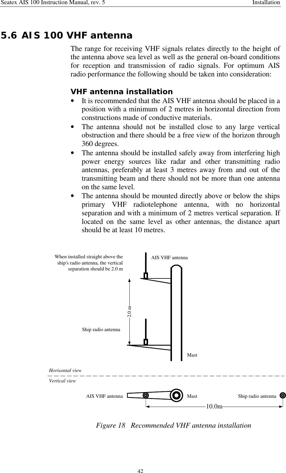
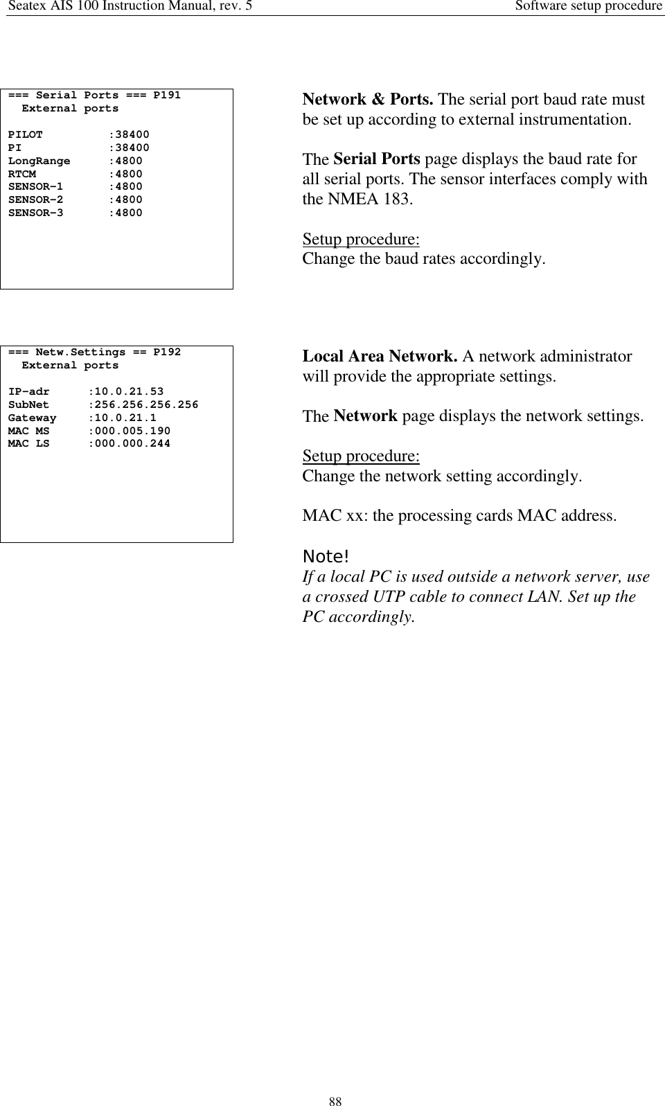
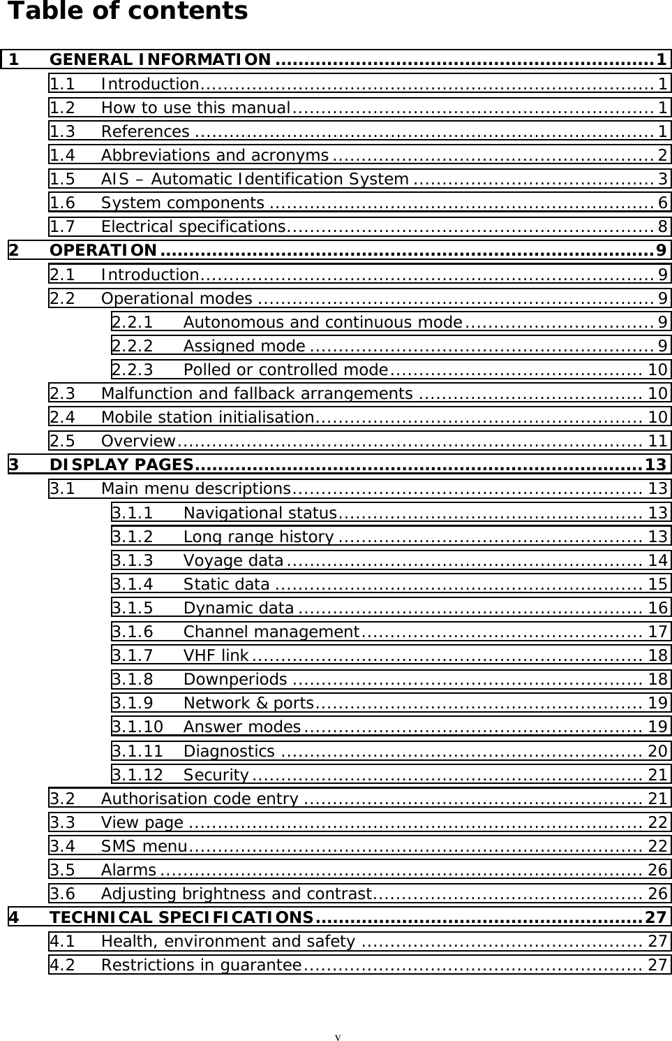
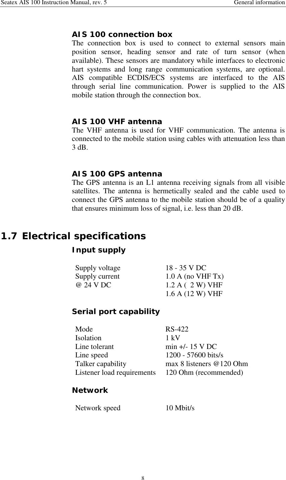
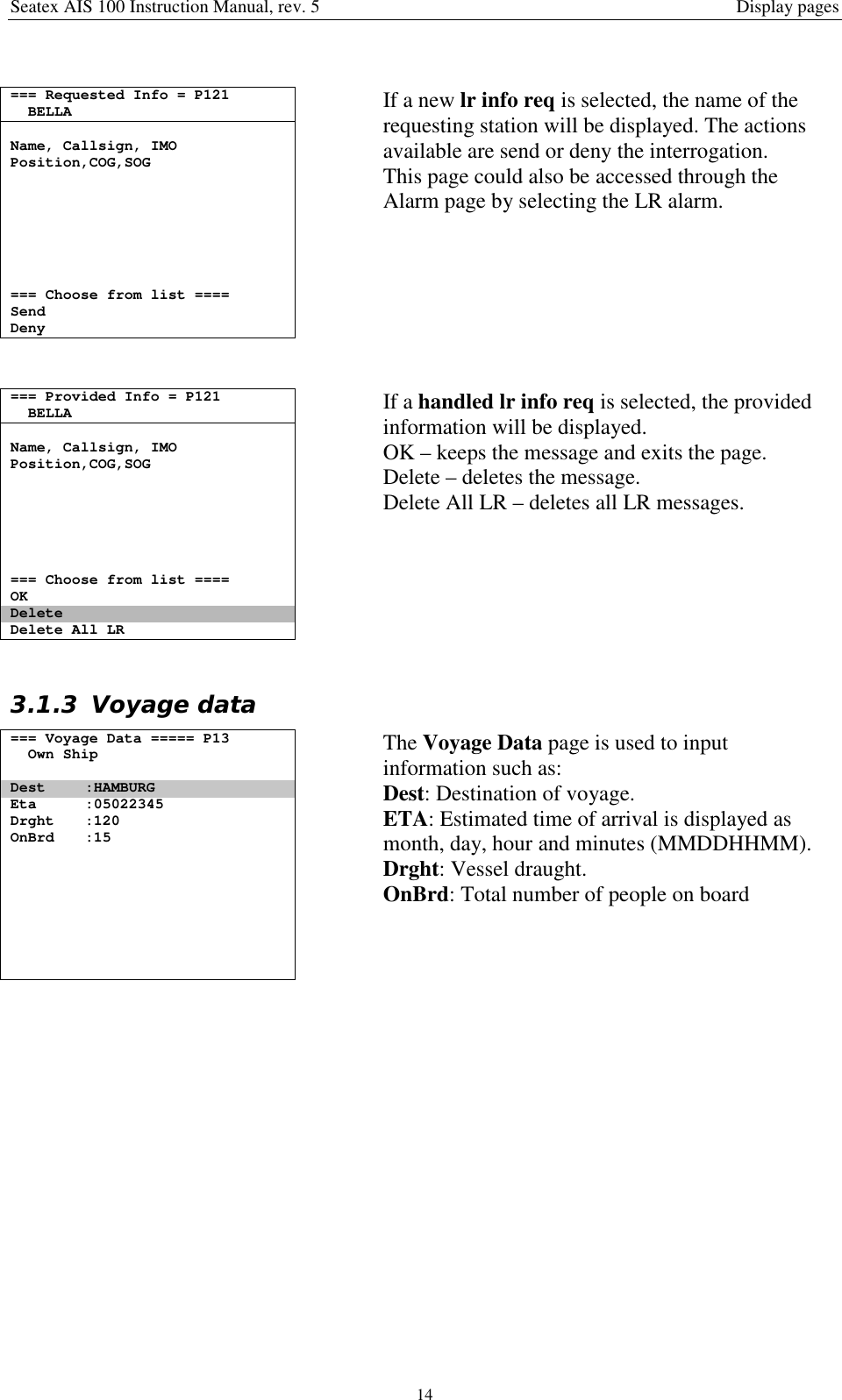
![Seatex AIS 100 Instruction Manual, rev. 5 General information2 [3] IEC 60945 Maritime navigation and radio communication equipmentand systems -General requirements - Methods of testing and requiredtest results. Third edition. [4] IEC 60950 Safety of information technology equipment. Edition 3.0,1999-04. [5] IEC 61162-1 Ed. 2.0 (2000-07) Maritime navigation and radiocommunication equipment and systems - Digital interfaces - Part 1:Single talker and multiple listeners. [6] IEC 61162-2 Ed. 1.0 (1998-09) Maritime navigation and radiocommunication equipment and systems - Digital interfaces - Part 2:Single talker and multiple listeners, high-speed transmission.1.4 Abbreviations and acronymsABK Addressed and Binary Broadcast AcknowledgementABM Addressed Binary and Safety Related MessageACA AIS Regional Channel AssignmentAIS Automatic Identification SystemALR AlarmBIIT Built In Integrity TestsBS Base StationCOG Course Over GroundDGPS Differential GPSDSC Digital Selective CallingECDIS Electronic Chart Display and Information SystemECS Electronic Chart SystemEMC Electromagnetic CompatibilityETA Estimated Time of ArrivalFATDMA Fixed Allocation TDMAGNSS Global Navigation Satellite SystemGPS Global Positioning SystemHDG HeadingIALA International Association of Lighthouse AuthoritiesIEC International Electrotechnical CommissionIMO International Maritime OrganisationLAN Local Area NetworkLED Light Emitting DiodeLR Long RangeMKD Minimum Keyboard DisplayMMSI Maritime Mobile Service IdentityMSG MessageN/A Not ApplicableNMEA National Marine Electronics AssociationPI Presentation InterfacePPS Pulse-per-secondPWR PowerROT Rate of TurnRTCM Radio Technical Commission of Maritime Service](https://usermanual.wiki/Kongsberg-Seatex-AS/AIS/User-Guide-331865-Page-10.png)
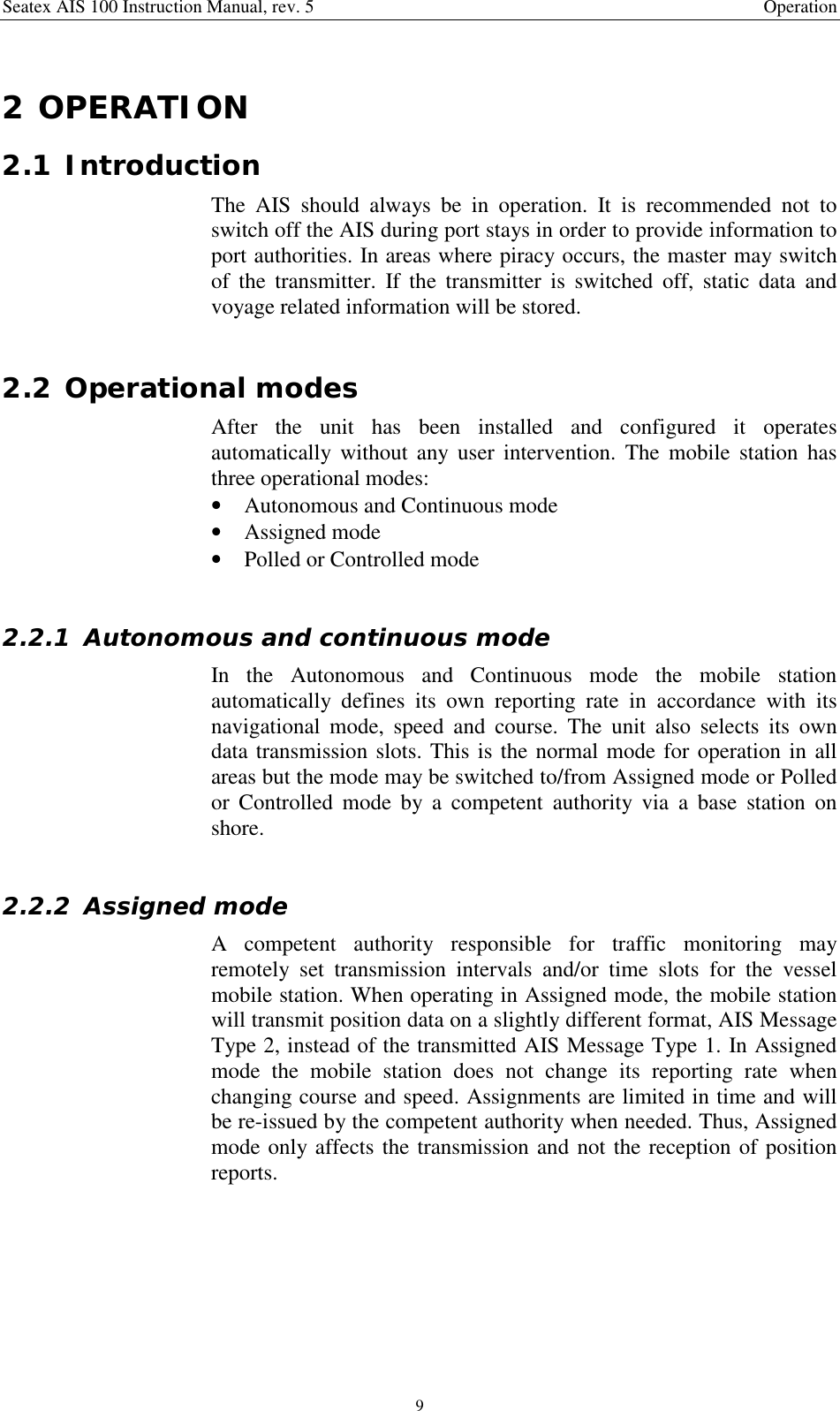
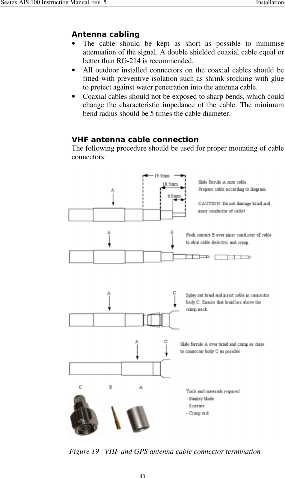
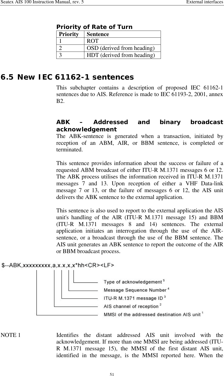
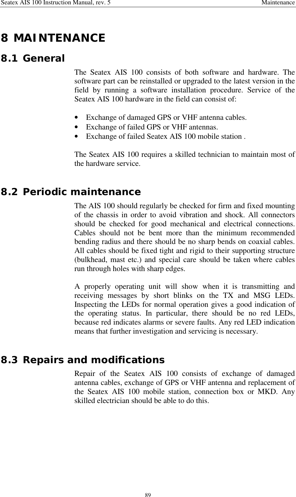
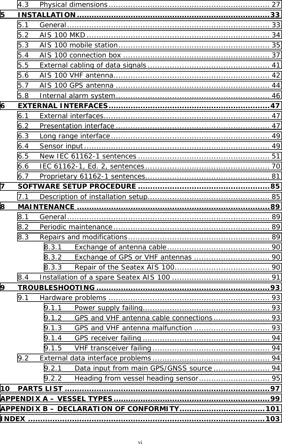
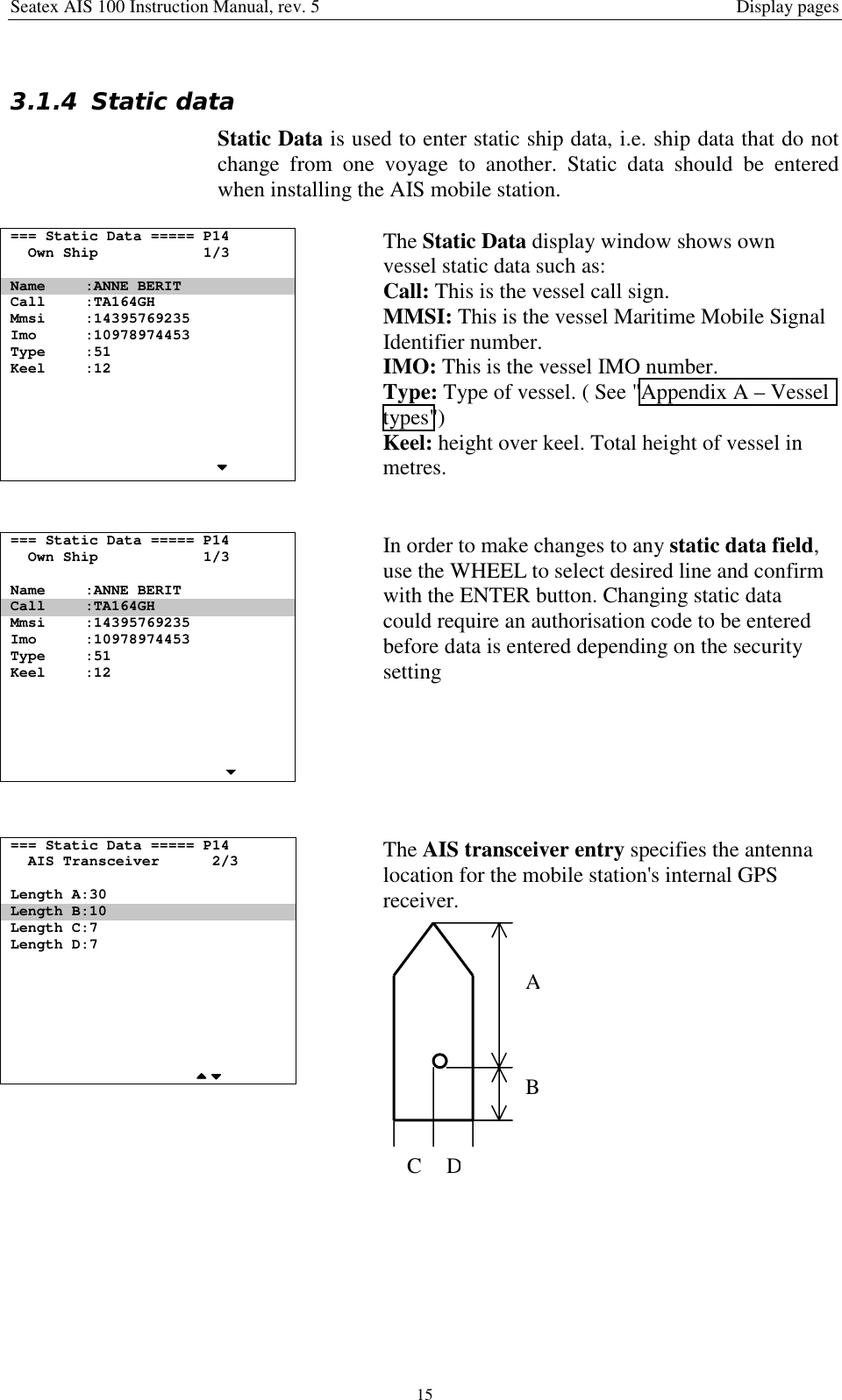
![Seatex AIS 100 Instruction Manual, rev. 5 Operation112.5 OverviewThe default view of the display shows vessel own position along withcourse (degrees) and speed (knots) over ground. Other vessels areshown in ascending order relative to own vessel position.Figure 3 Front display MKD unitButtons [Condition] Action FunctionVIEW [Always] Pressed once Displays the View page[Always] Pressed once Displays the Alarms pageALR [Always] Pressed more than once Displays the Long Range pageSMS [Always] Pressed Displays the SMS Menu pageMENU [Always] Pressed Displays the Main Menu pageBACK [Always] Pressed Displays the previous page[When present in lower right corner]Pressed Displays previous subpage[When writing/editing] Moves highlighting up[When choice is highlighted] Pressed Selects highlighted choiceENTER[When nothing is highlighted] Pressed No action[When present in lower right corner]Pressed Displays next subpage[When writing/editing] Pressed Moves highlighting down[When choice is highlighted] Rotated eitherway Moves highlighting](https://usermanual.wiki/Kongsberg-Seatex-AS/AIS/User-Guide-331865-Page-19.png)

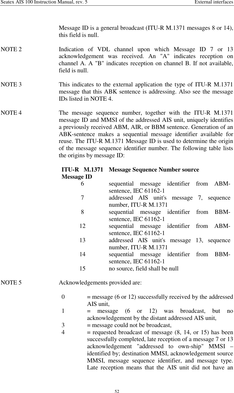
![Seatex AIS 100 Instruction Manual, rev. 5 Display pages203.1.11 Diagnostics=== Diagnostics ===== P1b1. Chn.Activity2. Port Activity3. SWR LevelsThe Diagnostics page gives additional technicaland operational information about the system.This is for service purposes by qualifiedpersonnel.=== Chn.Activity === P1b1Last Activity On ChnVDL TxA: Msg1 00:25VDL TxB: Msg1 00:25VDL RxA: Msg1 00:10VDL RxB: Msg5 00:30DSC Tx : Msg4 59:59DSC Rx : Msg4 59:59Displays the various messages received andtransmitted on VHF. The timestamp gives theelapsed time, in minutes and seconds, since thelast event on the channel.=== Port Activity == P1b2Last Activity On PortPI In : VDM 00:05PI Out: VDO 00:03LR In : LRI 01:00LR Out: LR2 00:35RTCM In : MSG 00:23RTCM Out: MSG 00:10SOR1 In : GGA 00:01SOR2 In : HDT 00:05SOR3 In : ROT 00:02Displays the messages on the serial interfacestimestamped as above.=== SWR Levels ===== P1b3Radio MeasurementsForward [W] : 2Reflected [W] : 0.003SWR : 1.1This is for service purposes by qualifiedpersonnel.](https://usermanual.wiki/Kongsberg-Seatex-AS/AIS/User-Guide-331865-Page-28.png)
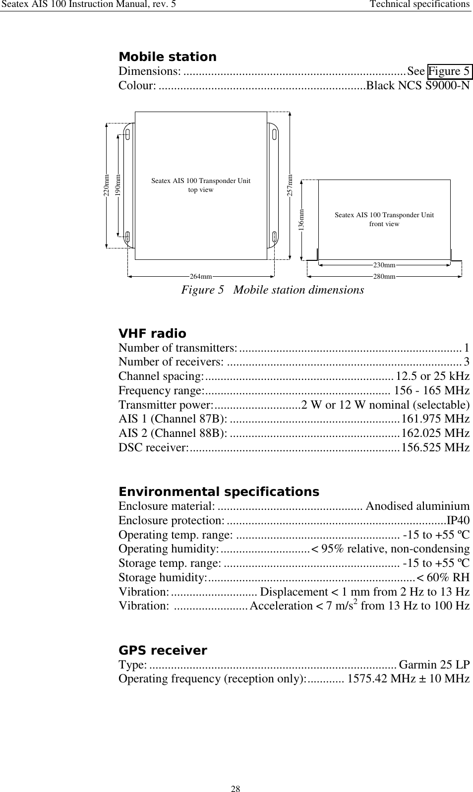
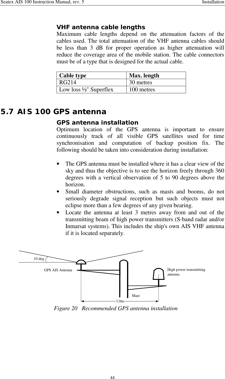
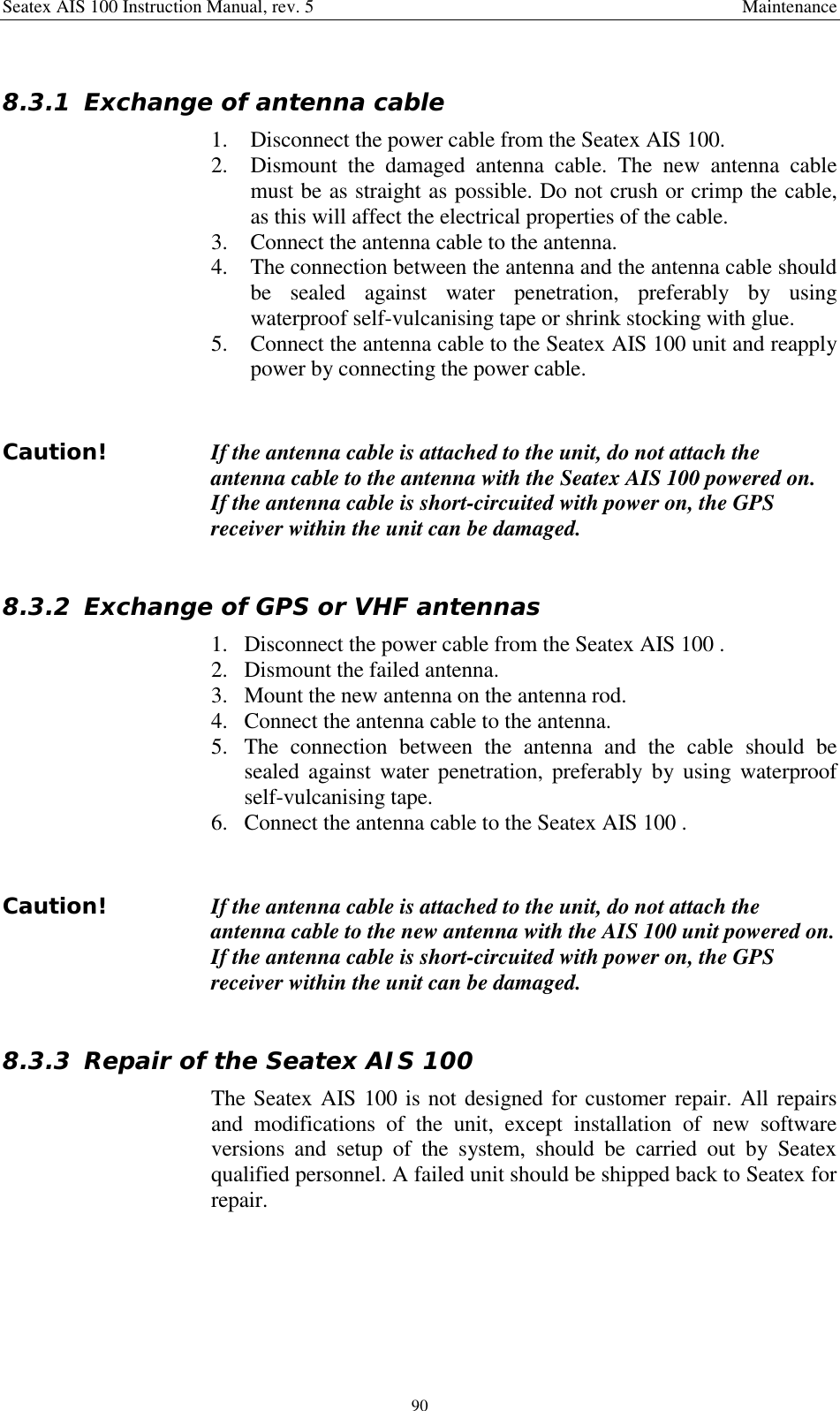
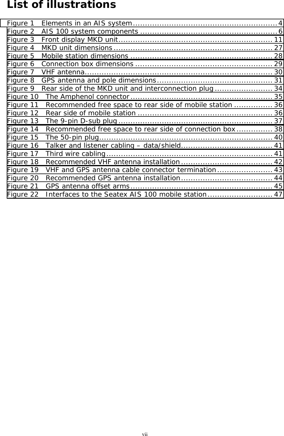
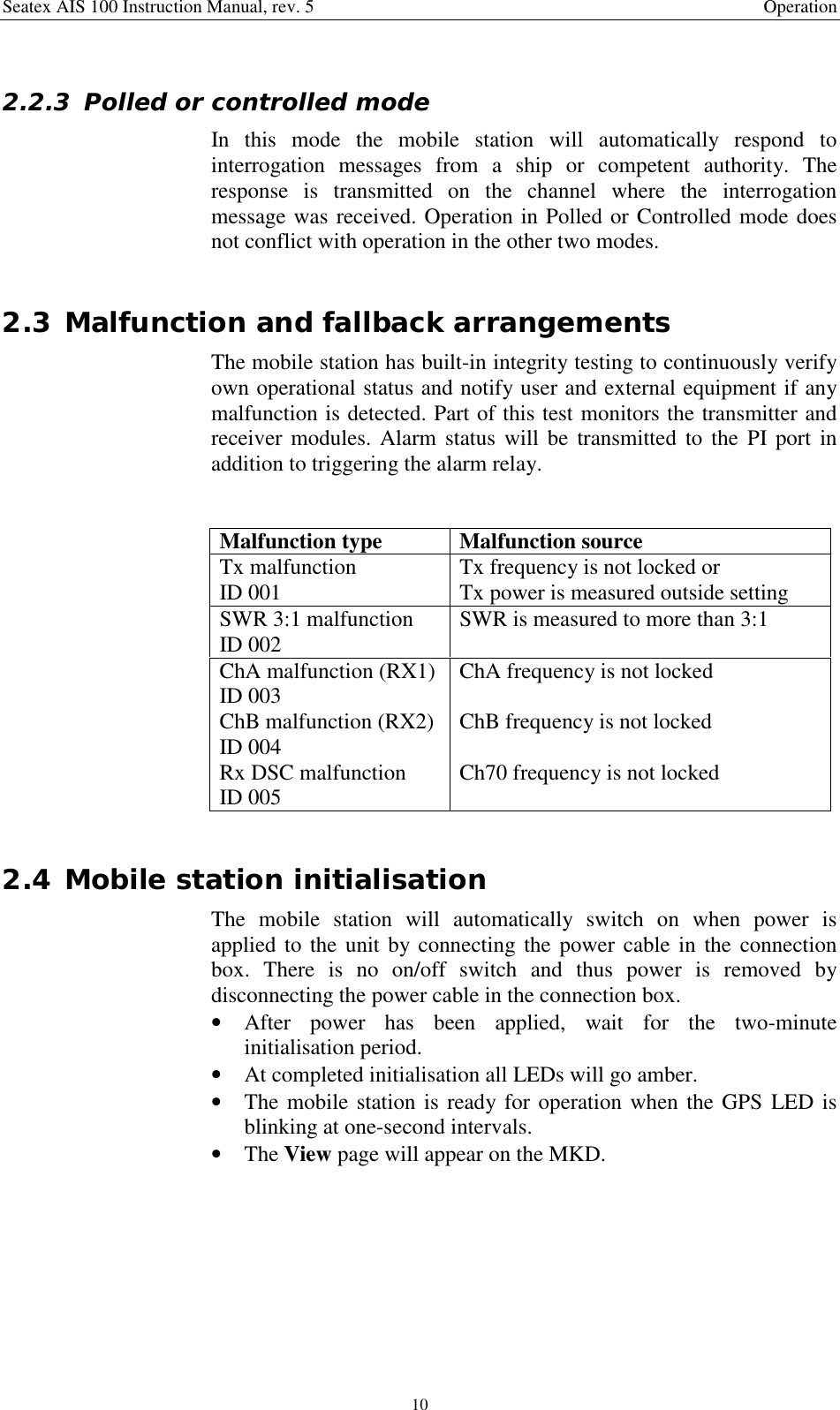
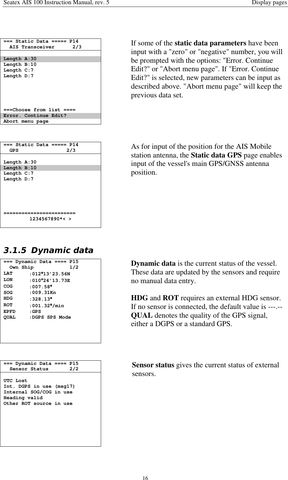
![Seatex AIS 100 Instruction Manual, rev. 5 Technical specifications274 TECHNICAL SPECIFICATIONS4.1 Health, environment and safetyOperation or troubleshooting of Seatex AIS 100 equipment will notimply any risk for high voltages, explosions or exposure to gas. TheSeatex AIS 100 is compliant with IEC 60950/EN60950 standardsregarding product safety (low voltage) and IEC 60945/EN60945standards on electromagnetic compatibility (immunity/radiation),vibration and climatic conditions.4.2 Restrictions in guaranteeThe liability of the manufacturer is limited to repair of the Seatex AIS100 only under the terms and conditions stated in reference [1], andexcludes consequential damages such as customer's loss of profit ordamage to other systems traceable back to Seatex AIS 100malfunction. The warranty does not cover malfunctions of the SeatexAIS 100 resulting from the following conditions:a) The customer has opened the mobile station.b) Over-voltage or incorrect power connection.4.3 Physical dimensionsAIS 100 MKD unitDimensions: ........................................................................See Figure 4Type:..............................................................Integrated keypad/displayBacklit display and keys:.......................................................AdjustableSeatex AIS 100 MKD Unitfront view144mm252mm238mm130mm37mmFigure 4 MKD unit dimensions](https://usermanual.wiki/Kongsberg-Seatex-AS/AIS/User-Guide-331865-Page-35.png)