Kongsberg Seatex AS AIS Seatex AIS 100/Simrad AI 70 User Manual Seatex AIS 100 Instruction Manual
Kongsberg Seatex AS Seatex AIS 100/Simrad AI 70 Seatex AIS 100 Instruction Manual
Seatex AIS 100 Instruction Manual
Seatex AIS 100
Instruction Manual
Blank page

iii
Document revisions
Document ID Rev. Date Reason for revision
0 - 3 Draft versions
4 2003-03-03 Updated NMEA descriptions
Man_instr_ais100_r5 5 2003-03-31 Minor update after internal revision
Software versions
This Instruction Manual applies to software version 1.06 and newer.
iv
Blank page
v
Table of contents
1 GENERAL INFORMATION ..................................................................1
1.1 Introduction...............................................................................1
1.2 How to use this manual...............................................................1
1.3 References ................................................................................1
1.4 Abbreviations and acronyms ........................................................2
1.5 AIS – Automatic Identification System ..........................................3
1.6 System components ...................................................................6
1.7 Electrical specifications................................................................8
2 OPERATION......................................................................................9
2.1 Introduction...............................................................................9
2.2 Operational modes .....................................................................9
2.2.1 Autonomous and continuous mode.................................9
2.2.2 Assigned mode ............................................................9
2.2.3 Polled or controlled mode............................................ 10
2.3 Malfunction and fallback arrangements ....................................... 10
2.4 Mobile station initialisation......................................................... 10
2.5 Overview................................................................................. 11
3 DISPLAY PAGES..............................................................................13
3.1 Main menu descriptions............................................................. 13
3.1.1 Navigational status..................................................... 13
3.1.2 Long range history ..................................................... 13
3.1.3 Voyage data.............................................................. 14
3.1.4 Static data ................................................................ 15
3.1.5 Dynamic data ............................................................ 16
3.1.6 Channel management................................................. 17
3.1.7 VHF link.................................................................... 18
3.1.8 Downperiods ............................................................. 18
3.1.9 Network & ports......................................................... 19
3.1.10 Answer modes........................................................... 19
3.1.11 Diagnostics ............................................................... 20
3.1.12 Security.................................................................... 21
3.2 Authorisation code entry ........................................................... 21
3.3 View page ............................................................................... 22
3.4 SMS menu............................................................................... 22
3.5 Alarms .................................................................................... 26
3.6 Adjusting brightness and contrast............................................... 26
4 TECHNICAL SPECIFICATIONS.........................................................27
4.1 Health, environment and safety ................................................. 27
4.2 Restrictions in guarantee........................................................... 27
vi
4.3 Physical dimensions.................................................................. 27
5 INSTALLATION...............................................................................33
5.1 General................................................................................... 33
5.2 AIS 100 MKD ........................................................................... 34
5.3 AIS 100 mobile station.............................................................. 35
5.4 AIS 100 connection box ............................................................ 37
5.5 External cabling of data signals .................................................. 41
5.6 AIS 100 VHF antenna................................................................ 42
5.7 AIS 100 GPS antenna ............................................................... 44
5.8 Internal alarm system............................................................... 46
6 EXTERNAL INTERFACES..................................................................47
6.1 External interfaces.................................................................... 47
6.2 Presentation interface ............................................................... 47
6.3 Long range interface................................................................. 49
6.4 Sensor input............................................................................ 49
6.5 New IEC 61162-1 sentences ...................................................... 51
6.6 IEC 61162-1, Ed. 2, sentences................................................... 70
6.7 Proprietary 61162-1 sentences................................................... 81
7 SOFTWARE SETUP PROCEDURE ......................................................85
7.1 Description of installation setup.................................................. 85
8 MAINTENANCE ...............................................................................89
8.1 General................................................................................... 89
8.2 Periodic maintenance................................................................ 89
8.3 Repairs and modifications.......................................................... 89
8.3.1 Exchange of antenna cable.......................................... 90
8.3.2 Exchange of GPS or VHF antennas ............................... 90
8.3.3 Repair of the Seatex AIS 100....................................... 90
8.4 Installation of a spare Seatex AIS 100 ........................................ 91
9 TROUBLESHOOTING .......................................................................93
9.1 Hardware problems .................................................................. 93
9.1.1 Power supply failing.................................................... 93
9.1.2 GPS and VHF antenna cable connections....................... 93
9.1.3 GPS and VHF antenna malfunction ............................... 93
9.1.4 GPS receiver failing .................................................... 94
9.1.5 VHF transceiver failing................................................ 94
9.2 External data interface problems................................................ 94
9.2.1 Data input from main GPS/GNSS source ....................... 94
9.2.2 Heading from vessel heading sensor............................. 95
10 PARTS LIST ....................................................................................97
APPENDIX A – VESSEL TYPES................................................................99
APPENDIX B – DECLARATION OF CONFORMITY...................................101
INDEX .................................................................................................103
vii
List of illustrations
Figure 1 Elements in an AIS system............................................................4
Figure 2 AIS 100 system components .........................................................6
Figure 3 Front display MKD unit................................................................11
Figure 4 MKD unit dimensions..................................................................27
Figure 5 Mobile station dimensions ...........................................................28
Figure 6 Connection box dimensions .........................................................29
Figure 7 VHF antenna..............................................................................30
Figure 8 GPS antenna and pole dimensions................................................31
Figure 9 Rear side of the MKD unit and interconnection plug........................34
Figure 10 The Amphenol connector...........................................................35
Figure 11 Recommended free space to rear side of mobile station ................36
Figure 12 Rear side of mobile station ........................................................ 36
Figure 13 The 9-pin D-sub plug................................................................37
Figure 14 Recommended free space to rear side of connection box...............38
Figure 15 The 50-pin plug........................................................................40
Figure 16 Talker and listener cabling – data/shield......................................41
Figure 17 Third wire cabling..................................................................... 41
Figure 18 Recommended VHF antenna installation......................................42
Figure 19 VHF and GPS antenna cable connector termination.......................43
Figure 20 Recommended GPS antenna installation......................................44
Figure 21 GPS antenna offset arms...........................................................45
Figure 22 Interfaces to the Seatex AIS 100 mobile station...........................47
viii
Blank page

Seatex AIS 100 Instruction Manual, rev. 5 General information
1
1 GENERAL INFORMATION
1.1 Introduction
Congratulations on the purchase of your new Seatex AIS 100 and
thank you for selecting what is one of the best AIS systems available
on the market today.
Kongsberg Seatex AS manufactures several positioning and
navigation products for all types of vessels, from fishery and merchant
marine vessels to advanced offshore and research vessels. Kongsberg
Seatex AS is located in Trondheim in the central part of Norway. The
company's involvements in positioning and navigation products began
in 1984 with equipment for offshore and research vessels. Professional
mariners around the world acknowledge the Seatex brand names as
the "leading edge" in advanced, accurate and reliable navigation and
positioning products.
1.2 How to use this manual
This manual is intended as a reference guide for operation, installation
and maintenance of the Seatex AIS 100 system. Great care has been
taken to simplify the setup and operation of the system.
Please take the time to read this manual to get a thorough
understanding of the Seatex AIS 100's components and operation, as
well as their relationship to other sensors interfaced to the system.
Before going into details about the Seatex AIS 100 a short
introduction to AIS – Automatic Identification system is presented.
The mobile station will also be referred to as a transponder.
1.3 References
[1] IEC 61993-2. MARITIME NAVIGATION AND
RADIOCOMMUNICATION EQUIPMENT AND SYSTEMS -
Automatic Identification Systems (AIS) Part 2: Class A Shipborne
equipment of the Universal Automatic Identification System (AIS) -
Operational and performance requirements, methods of test and
required test results. Committee draft for vote 2001-02-16.
[2] RECOMMENDATION ITU-R M.1371. TECHNICAL
CHARACTERISTICS FOR A UNIVERSAL SHIPBORNE
AUTOMATIC IDENTIFICATION SYSTEM USING TIME DIVISION
MULTIPLE ACCESS IN THE VHF MARITIME MOBILE BAND.
Draft Revision.

Seatex AIS 100 Instruction Manual, rev. 5 General information
2
[3] IEC 60945 Maritime navigation and radio communication equipment
and systems -General requirements - Methods of testing and required
test results. Third edition.
[4] IEC 60950 Safety of information technology equipment. Edition 3.0,
1999-04.
[5] IEC 61162-1 Ed. 2.0 (2000-07) Maritime navigation and radio
communication equipment and systems - Digital interfaces - Part 1:
Single talker and multiple listeners.
[6] IEC 61162-2 Ed. 1.0 (1998-09) Maritime navigation and radio
communication equipment and systems - Digital interfaces - Part 2:
Single talker and multiple listeners, high-speed transmission.
1.4 Abbreviations and acronyms
ABK Addressed and Binary Broadcast Acknowledgement
ABM Addressed Binary and Safety Related Message
ACA AIS Regional Channel Assignment
AIS Automatic Identification System
ALR Alarm
BIIT Built In Integrity Tests
BS Base Station
COG Course Over Ground
DGPS Differential GPS
DSC Digital Selective Calling
ECDIS Electronic Chart Display and Information System
ECS Electronic Chart System
EMC Electromagnetic Compatibility
ETA Estimated Time of Arrival
FATDMA Fixed Allocation TDMA
GNSS Global Navigation Satellite System
GPS Global Positioning System
HDG Heading
IALA International Association of Lighthouse Authorities
IEC International Electrotechnical Commission
IMO International Maritime Organisation
LAN Local Area Network
LED Light Emitting Diode
LR Long Range
MKD Minimum Keyboard Display
MMSI Maritime Mobile Service Identity
MSG Message
N/A Not Applicable
NMEA National Marine Electronics Association
PI Presentation Interface
PPS Pulse-per-second
PWR Power
ROT Rate of Turn
RTCM Radio Technical Commission of Maritime Service

Seatex AIS 100 Instruction Manual, rev. 5 General information
3
RX Receive
Seatex Kongsberg Seatex AS
SOG Speed Over Ground
SOTDMA Self Organising TDMA
SWR Standing Wave Ratio
TBD To Be Defined
TDMA Time Division Multiple Access
TX Transmit
TXT Text Message
UTC Universal Co-ordinated Time
VDL VHF Data Link
VDM VHF Data Link Message
VDO VHF Data Link Own Vessel Message
VHF Very High Frequency
VTS Vessel Traffic Service
1.5 AIS – Automatic Identification System
AIS is an identification system that uses VHF communication to
transmit and receive AIS data. AIS operates primarily on two
dedicated VHF channels, AIS 1 – 161,975 MHz and AIS 2 – 162,025
MHz. Where these channels are not available regionally, the AIS can
be set to alternate designated channels.
The AIS mobile station broadcasts the vessel's position, speed and
course over ground as well as static and voyage related information.
Short safety related text messages can be sent between vessels or
broadcast from shore based AIS stations or Aids to Navigation like
buoys and lighthouses. The on-board installed mobile station is
designed to operate automatically and as a stand-alone unit. When not
transmitting, the mobile station listens for position information from
other vessels or shore based stations.
Seatex AIS 100 Instruction Manual, rev. 5 General information
4
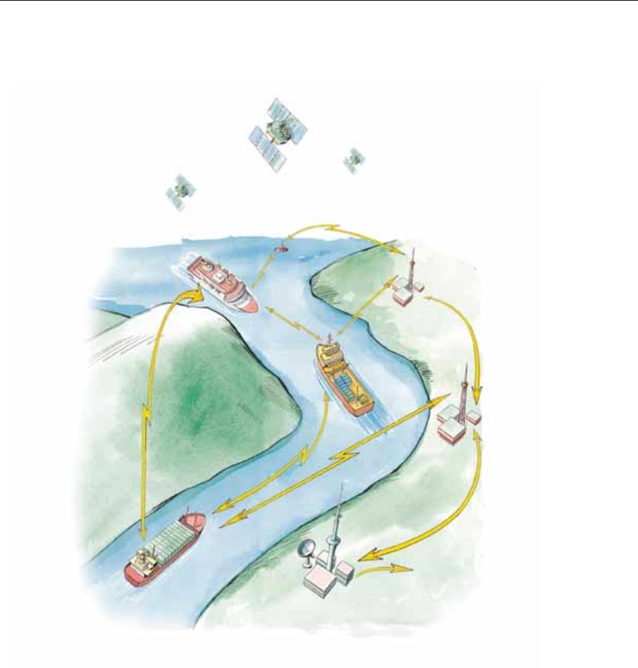
Figure 1 Elements in an AIS system
The system broadcasts data using the SOTDMA (Self-organised Time
Division Multiple Access) data protocol. Each minute is divided into
4500 time slots, enabling simultaneous transmission of up to 500
stations.
Coverage
The system radio coverage range is similar to other VHF applications
and is dependent on the height of the antenna. The propagation differs
from that of a radar, due to the longer wavelength, so it is possible to
"see" around bends and behind islands if the landmasses are not too
high. A typical value to be expected at sea is 20 nautical miles.
AIS Base Station
VTS Centre
GNSS Satellites
AIS VHF Lin
k
AIS VHF Lin
k

Seatex AIS 100 Instruction Manual, rev. 5 General information
5
AIS information content
AIS type of information is exchanged automatically between vessels,
vessels and shore based stations and vessel and Aids to Navigation
like buoys and lighthouses. The information transmitted by the AIS
mobile stations is grouped in four categories:
Static Data
• MMSI (Maritime Mobile Service Identity) number
• Call sign and name
• IMO number
• Length and beam
• Type of ship
• Location of position fixing antennas on the ship
Voyage Related Data
• Ship's draught
• Hazardous cargo type
• Destination and ETA (at Master's discretion)
Dynamic Data
• Position with accuracy indication and integrity status
• Time in UTC
• COG (Course over ground)
• SOG (Speed over ground)
• Heading
• Navigational status
• Rate of turn
Safety-related Messages
• Reading and writing short safety related messages
Data reporting and transmission rates
AIS data as stated above is autonomously sent at different update rates
and thus reporting rates are dependent on the ship's navigational
mode. Dynamic information is dependent on speed and course
alteration while static and voyage related data are transmitted every 6
minutes or on request. Thus fast ferries will report their navigational
data at a higher update rate than ships at anchor.
Seatex AIS 100 Instruction Manual, rev. 5 General information
6
Type of Ship Reporting
Interval
Ship at anchor 3 min.
Ship 0 to 14 knots 12 sec.
Ship 0 to 14 knots and changing course 4 sec.
Ship 14 to 23 knots 6 sec.
Ship 14 to 23 knots and changing course 2 sec.
Ship > 23 knots 3 sec.
Ship > 23 knots and changing course 2 sec.
All data input to the AIS mobile stations is based on the NMEA 0183
data protocol. Messages sent on VHF are based on the AIS data
protocol, which defines several Message Types containing different
types of information.
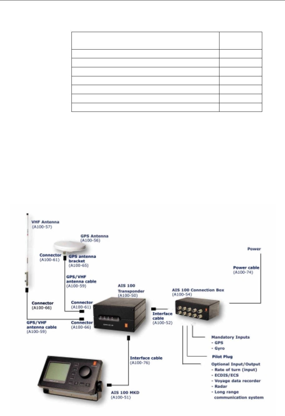
1.6 System components
The Seatex AIS 100 system consists of the following units:
Figure 2 AIS 100 system components

Seatex AIS 100 Instruction Manual, rev. 5 General information
7
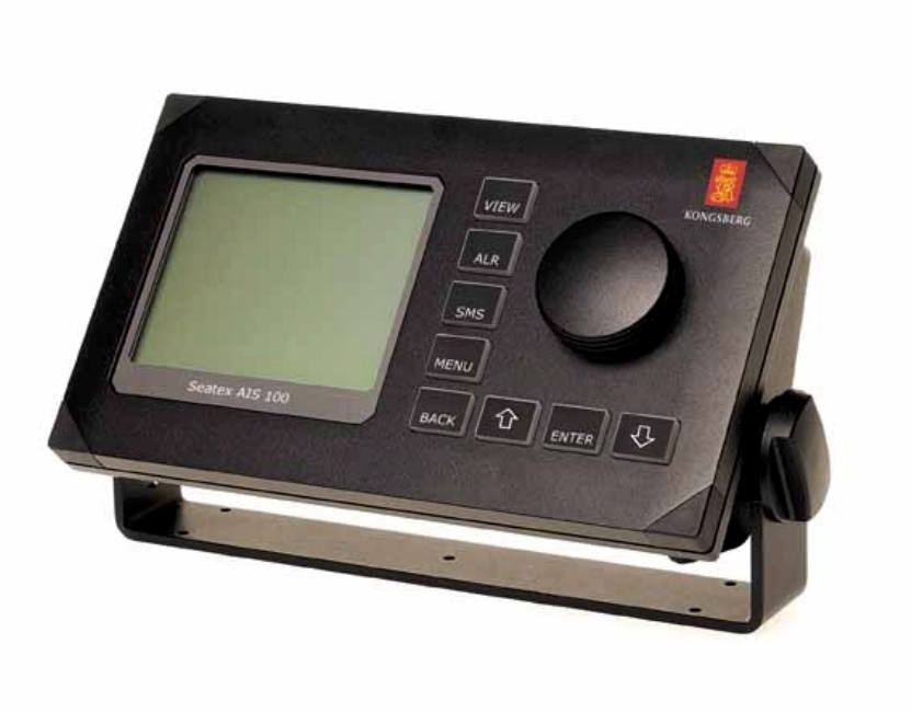
AIS 100 Minimum Keyboard and Display (MKD)
The MKD unit provides a simple user interface to the mobile station.
The keypads on the MKD can be used to navigate between dedicated
menus used for configuration and display of vessel navigation data.
Text messages can also be entered into the MKD and transmitted to
other vessels or shore based AIS stations providing warnings or other
relevant navigation information. Thus the MKD provides basic
presentation of configuration data, position data and text messages. If
the AIS has been interfaced to the on-board ECDIS system or radar
the information displayed on the MKD can also be displayed on an
AIS compatible ECDIS or ECS systems.
AIS 100 mobile station
The mobile station incorporates two VHF receivers, configured to
operate on the predefined AIS frequencies for the region, one VHF
transmitter transmitting on all required frequencies and one DSC
receiver. The mobile station also incorporates a GPS receiver and a
processor. The internal GPS receiver, which is capable of receiving
differential corrections for increased position accuracy, is used for
time synchronisation and as a backup position sensor. For AIS data
transmission, the Self Organised Time Division Multiple Access
(SOTDMA) data protocol is used. SOTDMA enables a large number
of vessels to receive and transmit AIS data at the same time.
Front LED indicators
The LED indicators on the front of the mobile station can be used to
monitor status as well as data reception and transmission.
Led Colour Description
TX Off
Amber
Green
Red
Transmitter idle
Transmitting on AIS channel B
Transmitting on AIS channel A
Transmitter turned off
MSG Off
Amber
Green
No message/report being received
Message/report received on channel B
Message/report being received on channel A
GPS Amber
Green Indirect synchronisation free run
Internal GPS OK. GPS synch selected
ALM Off
Red No alarm
Alarm. Alarm relay activated
PWR Green Indicates powered unit

Seatex AIS 100 Instruction Manual, rev. 5 General information
8
AIS 100 connection box
The connection box is used to connect to external sensors main
position sensor, heading sensor and rate of turn sensor (when
available). These sensors are mandatory while interfaces to electronic
hart systems and long range communication systems, are optional.
AIS compatible ECDIS/ECS systems are interfaced to the AIS
through serial line communication. Power is supplied to the AIS
mobile station through the connection box.
AIS 100 VHF antenna
The VHF antenna is used for VHF communication. The antenna is
connected to the mobile station using cables with attenuation less than
3 dB.
AIS 100 GPS antenna
The GPS antenna is an L1 antenna receiving signals from all visible
satellites. The antenna is hermetically sealed and the cable used to
connect the GPS antenna to the mobile station should be of a quality
that ensures minimum loss of signal, i.e. less than 20 dB.
1.7 Electrical specifications
Input supply
Supply voltage 18 - 35 V DC
Supply current
@ 24 V DC 1.0 A (no VHF Tx)
1.2 A ( 2 W) VHF
1.6 A (12 W) VHF
Serial port capability
Mode RS-422
Isolation 1 kV
Line tolerant min +/- 15 V DC
Line speed 1200 - 57600 bits/s
Talker capability max 8 listeners @120 Ohm
Listener load requirements 120 Ohm (recommended)
Network
Network speed 10 Mbit/s

Seatex AIS 100 Instruction Manual, rev. 5 Operation
9
2 OPERATION
2.1 Introduction
The AIS should always be in operation. It is recommended not to
switch off the AIS during port stays in order to provide information to
port authorities. In areas where piracy occurs, the master may switch
of the transmitter. If the transmitter is switched off, static data and
voyage related information will be stored.
2.2 Operational modes
After the unit has been installed and configured it operates
automatically without any user intervention. The mobile station has
three operational modes:
• Autonomous and Continuous mode
• Assigned mode
• Polled or Controlled mode
2.2.1 Autonomous and continuous mode
In the Autonomous and Continuous mode the mobile station
automatically defines its own reporting rate in accordance with its
navigational mode, speed and course. The unit also selects its own
data transmission slots. This is the normal mode for operation in all
areas but the mode may be switched to/from Assigned mode or Polled
or Controlled mode by a competent authority via a base station on
shore.
2.2.2 Assigned mode
A competent authority responsible for traffic monitoring may
remotely set transmission intervals and/or time slots for the vessel
mobile station. When operating in Assigned mode, the mobile station
will transmit position data on a slightly different format, AIS Message
Type 2, instead of the transmitted AIS Message Type 1. In Assigned
mode the mobile station does not change its reporting rate when
changing course and speed. Assignments are limited in time and will
be re-issued by the competent authority when needed. Thus, Assigned
mode only affects the transmission and not the reception of position
reports.

Seatex AIS 100 Instruction Manual, rev. 5 Operation
10
2.2.3 Polled or controlled mode
In this mode the mobile station will automatically respond to
interrogation messages from a ship or competent authority. The
response is transmitted on the channel where the interrogation
message was received. Operation in Polled or Controlled mode does
not conflict with operation in the other two modes.
2.3 Malfunction and fallback arrangements
The mobile station has built-in integrity testing to continuously verify
own operational status and notify user and external equipment if any
malfunction is detected. Part of this test monitors the transmitter and
receiver modules. Alarm status will be transmitted to the PI port in
addition to triggering the alarm relay.
Malfunction type Malfunction source
Tx malfunction
ID 001 Tx frequency is not locked or
Tx power is measured outside setting
SWR 3:1 malfunction
ID 002 SWR is measured to more than 3:1
ChA malfunction (RX1)
ID 003 ChA frequency is not locked
ChB malfunction (RX2)
ID 004 ChB frequency is not locked
Rx DSC malfunction
ID 005 Ch70 frequency is not locked
2.4 Mobile station initialisation
The mobile station will automatically switch on when power is
applied to the unit by connecting the power cable in the connection
box. There is no on/off switch and thus power is removed by
disconnecting the power cable in the connection box.
• After power has been applied, wait for the two-minute
initialisation period.
• At completed initialisation all LEDs will go amber.
• The mobile station is ready for operation when the GPS LED is
blinking at one-second intervals.
• The View page will appear on the MKD.
Seatex AIS 100 Instruction Manual, rev. 5 Operation
11
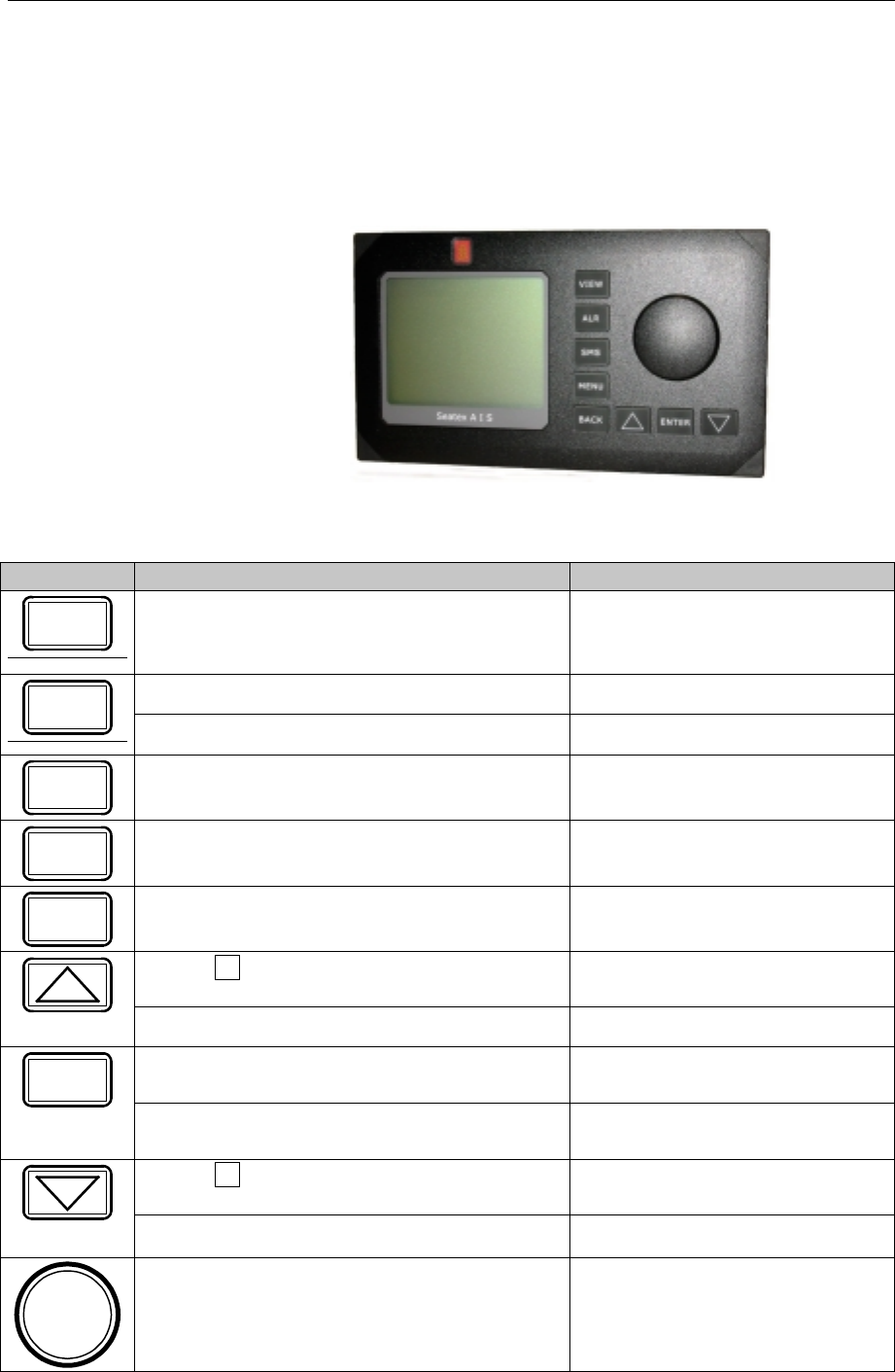
2.5 Overview
The default view of the display shows vessel own position along with
course (degrees) and speed (knots) over ground. Other vessels are
shown in ascending order relative to own vessel position.
Figure 3 Front display MKD unit
Buttons [Condition] Action Function
VIEW [Always] Pressed once Displays the View page
[Always] Pressed once Displays the Alarms page
ALR [Always] Pressed more than once Displays the Long Range page
SMS [Always] Pressed Displays the SMS Menu page
MENU [Always] Pressed Displays the Main Menu page
BACK [Always] Pressed Displays the previous page
[When present in lower right corner]
Pressed Displays previous subpage
[When writing/editing] Moves highlighting up
[When choice is highlighted] Pressed Selects highlighted choice
ENTER
[When nothing is highlighted] Pressed No action
[When present in lower right corner]
Pressed Displays next subpage
[When writing/editing] Pressed Moves highlighting down
[When choice is highlighted] Rotated either
way Moves highlighting

Seatex AIS 100 Instruction Manual, rev. 5 Operation
12
Blank page

Seatex AIS 100 Instruction Manual, rev. 5 Display pages
13
3 DISPLAY PAGES
The Seatex AIS 100 provides several display pages and menus
available for setup and display of information as well as editing of text
messages. In this chapter all display windows available are presented
and their contents discussed to enable easy operation and use of the
AIS mobile station.
3.1 Main menu descriptions
=== Main Menu ======== P1
1. Nav.Status
2. Long Range history
3. Voyage Data
4. Static Data
5. Dynamic Data
6. Chn.Management
7. VHF Link
8. Downperiods
9. Network & Ports
a. Answer Mode
b. Diagnostics
c. Security
1.06.zz
This is the Main Menu page. Press the MENU
button on the MKD unit to access the main menu.
The program version is shown in the lower part of
the page, where 1.06 is the version number and zz
the revision.
3.1.1 Navigational status
=== Nav Status ====== P11
Own Ship
AT ANCHOR
=== Choose from list ====
AT ANCHOR
UNDER WAY USING ENGINE
UNDER WAY SAILING
ENGAGED IN FISHING
NOT UNDER COMMAND
RESTR.MANOEUVRABILITY
CONSTRAINED BY DRAUGHT
MOORED
AGROUND
The Nav Status page enables the operator to
change the navigational status from a pre-defined
list. Options are AT ANCHOR, UNDER WAY
USING ENGINE, UNDER WAY SAILING,
ENGAGED IN FISHING, etc.
3.1.2 Long range history
=== Long Range ====== P12
Own Ship
LR INFO REQ. 03Jan 1230
lr info req. 01Jan 1145
lr info req. 01Jan 1134
The Long Range page contains active and
resolved Long Range interrogation requests.

Seatex AIS 100 Instruction Manual, rev. 5 Display pages
14
=== Requested Info = P121
BELLA
Name, Callsign, IMO
Position,COG,SOG
=== Choose from list ====
Send
Deny
If a new lr info req is selected, the name of the
requesting station will be displayed. The actions
available are send or deny the interrogation.
This page could also be accessed through the
Alarm page by selecting the LR alarm.
=== Provided Info = P121
BELLA
Name, Callsign, IMO
Position,COG,SOG
=== Choose from list ====
OK
Delete
Delete All LR
If a handled lr info req is selected, the provided
information will be displayed.
OK – keeps the message and exits the page.
Delete – deletes the message.
Delete All LR – deletes all LR messages.
3.1.3 Voyage data
=== Voyage Data ===== P13
Own Ship
Dest :HAMBURG
Eta :05022345
Drght :120
OnBrd :15
The Voyage Data page is used to input
information such as:
Dest: Destination of voyage.
ETA: Estimated time of arrival is displayed as
month, day, hour and minutes (MMDDHHMM).
Drght: Vessel draught.
OnBrd: Total number of people on board

Seatex AIS 100 Instruction Manual, rev. 5 Display pages
15
3.1.4 Static data
Static Data is used to enter static ship data, i.e. ship data that do not
change from one voyage to another. Static data should be entered
when installing the AIS mobile station.
=== Static Data ===== P14
Own Ship 1/3
Name :ANNE BERIT
Call :TA164GH
Mmsi :14395769235
Imo :10978974453
Type :51
Keel :12
The Static Data display window shows own
vessel static data such as:
Call: This is the vessel call sign.
MMSI: This is the vessel Maritime Mobile Signal
Identifier number.
IMO: This is the vessel IMO number.
Type: Type of vessel. ( See "Appendix A – Vessel
types")
Keel: height over keel. Total height of vessel in
metres.
=== Static Data ===== P14
Own Ship 1/3
Name :ANNE BERIT
Call :TA164GH
Mmsi :14395769235
Imo :10978974453
Type :51
Keel :12
In order to make changes to any static data field,
use the WHEEL to select desired line and confirm
with the ENTER button. Changing static data
could require an authorisation code to be entered
before data is entered depending on the security
setting
=== Static Data ===== P14
AIS Transceiver 2/3
Length A:30
Length B:10
Length C:7
Length D:7
The AIS transceiver entry specifies the antenna
location for the mobile station's internal GPS
receiver.
A
B
C
D

Seatex AIS 100 Instruction Manual, rev. 5 Display pages
16
=== Static Data ===== P14
AIS Transceiver 2/3
Length A:30
Length B:10
Length C:7
Length D:7
===Choose from list ====
Error. Continue Edit?
Abort menu page
If some of the static data parameters have been
input with a "zero" or "negative" number, you will
be prompted with the options: "Error. Continue
Edit?" or "Abort menu page". If "Error. Continue
Edit?" is selected, new parameters can be input as
described above. "Abort menu page" will keep the
previous data set.
=== Static Data ===== P14
GPS 2/3
Length A:30
Length B:10
Length C:7
Length D:7
========================
1234567890*< >
As for input of the position for the AIS Mobile
station antenna, the Static data GPS page enables
input of the vessel's main GPS/GNSS antenna
position.
3.1.5 Dynamic data
=== Dynamic Data ==== P15
Own Ship 1/2
LAT :012°
°°
°13’23.56N
LON :010°
°°
°24’13.73E
COG :007.58°
°°
°
SOG :009.31Kn
HDG :328.13°
°°
°
ROT :001.32°
°°
°/min
EPFD :GPS
QUAL :DGPS SPS Mode
Dynamic data is the current status of the vessel.
These data are updated by the sensors and require
no manual data entry.
HDG and ROT requires an external HDG sensor.
If no sensor is connected, the default value is ---.--
QUAL denotes the quality of the GPS signal,
either a DGPS or a standard GPS.
=== Dynamic Data ==== P15
Sensor Status 2/2
UTC Lost
Int. DGPS in use (msg17)
Internal SOG/COG in use
Heading valid
Other ROT source in use
Sensor status gives the current status of external
sensors.

Seatex AIS 100 Instruction Manual, rev. 5 Display pages
17
3.1.6 Channel management
=== Chn Management == P15
1. Edit Cur.Reg.
2. View Regions
3. Add Region .
Channel Management is used to configure
different radio channels for different chart zones.
Maximum 8 zones can be configured by input. A
zone is defined by the latitude and longitude of its
upper right (UR) corner and lower left (LL)
corner. When configured, the dedicated AIS
frequencies will automatically be used by the
system when the vessel position is inside the
geographically defined area. The main menu has
three options for channel management, which are
described in the following.
=== Edit Cur.Reg. ==== P151
RECTANGLE-2
ChnA :143
ChnB :144
RxTxMode :TxA/TxB,RxA/RxB
TxPower :High
LAT NE :012°
°°
°13’23.56N
LON NE :132°
°°
°36’14.02E
LAT SW :034°
°°
°56’21.06N
LON SW :125°
°°
°56’12.21E
BW A :Hi
BW B :Hi
Zone :2
The Edit Current Region page enables the
operator to change channels for the two AIS radio
receivers. The TxPower can only be set to High or
Low. If High is selected, the transmission power is
set to 12.5 W and if Low is selected, the
transmission power is set to 2 W. BW A and BW
B is the bandwidth settings for the VHF.
The selections are Default or Narrow. Default is
the maximum bandwidth allowed for this channel
(25 kHz or 12.5 kHz). Narrow denotes 12.5 kHz.
The user is only allowed to decrease the
bandwidth. Zone denotes the size of the transition
area in nautical miles outside of the region.
=== View Regions ==== P152
RECTANGLE-1 1/8
ChnA :143
ChnB :144
RxTxMode :TxA/TxB,RxA/RxB
TxPower :High
LAT NE :012°
°°
°13’23.56N
LON NE :132°
°°
°36’14.02E
LAT SW :034°
°°
°56’21.06N
LON SW :125°
°°
°56’12.21E
BW A :Hi
BW B :Hi
Zone :2
The View Regions page displays all defined
regions. This is a read only page and thus no
configuration changes can be made. The view
regions may consist of up to 8 pages and the
ARROW DOWN button can be used to display
more regions.

Seatex AIS 100 Instruction Manual, rev. 5 Display pages
18
=== Add Regions ====== P153
RECTANGLE-7
ChnA :56
ChnB :58
RxTxMode :TxA,RxA/RxB
TxPower :High
LAT NE :012°
°°
°13’23.56N
LON NE :132°
°°
°36’14.02E
LAT SW :034°
°°
°56’21.06N
LON SW :125°
°°
°56’12.21E
BW A :Hi
BW B :Hi
Zone :3
The Add regions page is for creating new regions
by manual input.
3.1.7 VHF link
=== VHF Link ======== P17
Ais Transceiver
ChnA :2087
ChnB :2088
TxPower :HIGH
BW A :Default
BW B :Default
Transmitter :TxON
The VHF link page displays the current VHF
settings. In addition to the normal VHF settings,
the transmitter can be turned off in this menu. This
option should only be used in situations where
transmission would endanger the ship, e.g. in war-
like situations, piracy etc.
3.1.8 Downperiods
=== Downperiods ===== P18
From To
*01:30 20Nov 02:35 20Nov
11:00 19Nov 12:35 19Nov
16:20 16Nov 20:00 16Nov
11:30 15Nov 02:35 15Nov
*08:30 15Nov 02:35 15Nov
15:30 13Nov 02:35 13Nov
01.30 11Nov 02:35 11Nov
#11:30 10Nov 12:35 12Nov
#09:40 09Oct 10:10 09Oct
19:20 05Oct 15.10 06Oct
The Downperiods page displays when the mobile
station has been out of operation. Out of operation
is either when the power has been off, the
transmitter has been disabled (prefixed with #) or
when a TX malfunction has occurred (prefixed
with *).

Seatex AIS 100 Instruction Manual, rev. 5 Display pages
19
3.1.9 Network & ports
=== Network & Ports = P19
1. Serial Ports
2. Netw.Settings
The Network and ports page gives access to the
configuration settings for external serial ports and
network (LAN) settings.
=== Serial Ports === P191
External ports
PILOT :38400
PI :38400
LongRange :4800
RTCM :4800
SENSOR-1 :4800
SENSOR-2 :4800
SENSOR-3 :4800
The Serial ports page displays the baud rate for
all serial ports. Only the baud rates can be
changed. The sensor interfaces comply with
NMEA 0183.
=== Netw.Settings == P192
External ports
IP-adr :10.0.21.53
SubNet :255.255.255.0
Gateway :10.0.21.1
MAC MS :000.005.190
MAC LS :000.000.230
The Network page displays the network settings.
A network administrator for a Local Area
Network will provide the appropriate settings for
this page.
3.1.10 Answer modes
=== Answer Mode ==== P1a
Current Settings
Long Range :Automatic
VDL Response :On
====Choose from list ===
Manual
Automatic
The Answer mode page configures the polling
operation of the mobile station. The Long Range
requires additional external equipment for the
carrier system (Inmarsat …). The VDL response
configures the behaviour on normal VHF polling.
The normal operation is ON.

Seatex AIS 100 Instruction Manual, rev. 5 Display pages
20
3.1.11 Diagnostics
=== Diagnostics ===== P1b
1. Chn.Activity
2. Port Activity
3. SWR Levels
The Diagnostics page gives additional technical
and operational information about the system.
This is for service purposes by qualified
personnel.
=== Chn.Activity === P1b1
Last Activity On Chn
VDL TxA: Msg1 00:25
VDL TxB: Msg1 00:25
VDL RxA: Msg1 00:10
VDL RxB: Msg5 00:30
DSC Tx : Msg4 59:59
DSC Rx : Msg4 59:59
Displays the various messages received and
transmitted on VHF. The timestamp gives the
elapsed time, in minutes and seconds, since the
last event on the channel.
=== Port Activity == P1b2
Last Activity On Port
PI In : VDM 00:05
PI Out: VDO 00:03
LR In : LRI 01:00
LR Out: LR2 00:35
RTCM In : MSG 00:23
RTCM Out: MSG 00:10
SOR1 In : GGA 00:01
SOR2 In : HDT 00:05
SOR3 In : ROT 00:02
Displays the messages on the serial interfaces
timestamped as above.
=== SWR Levels ===== P1b3
Radio Measurements
Forward [W] : 2
Reflected [W] : 0.003
SWR : 1.1
This is for service purposes by qualified
personnel.

Seatex AIS 100 Instruction Manual, rev. 5 Display pages
21
3.1.12 Security
=== Security ======== P1C
Authorisation
L1 PIN Code :*******
L2 PIN Code :*******
Nav.Status :0
Voyage Data :0
Static Data :0
Chn.Mgmt :1
VHF Link :1
Serial Ports :1
Netw.Settings :1
Answer Mode :0
The Security page contains authorisation setup for
the mobile station. There are two authorisation
code levels. On this page the PIN codes can be set
and a number of menu pages can be protected
against unauthorised change. PIN codes, see
chapter 7. The Level 2 PIN code (L2) is valid on
all pages requiring L1 authentication1. The
possible levels are:
0 No authorisation code
1 Use L1 or L2 PIN code
2 Use L2 PIN code
All entries on this page are protected by L2 PIN
code.
3.2 Authorisation code entry
This page will appear when modifying data protected by the security
page.
========================
Enter authorisation code
PIN: **
========================
ABCDEFGHIJKLMNO
PQRSTUVWXYZ1234
567890.,!\”@<
<<
<←
←←
←↵
↵↵
↵
In order to enter the Authorisation code use the
WHEEL to select symbols and confirm each input
using the ENTER button. When all symbols in the
authorisation code have been input, select the ↵
↵↵
↵
symbol (confirming to the system that the last
symbol within the authorisation code has been
entered) and finally press the ENTER button.
1 Once authenticated with L1 or L2 PIN code, the authentication is valid until the View page has been displayed
for 5 seconds or more. To protect the AIS security systems, the MKD returns to the View page when not used
for 15 minutes or more. In high security applications we recommend manually returning to the View page for 5
seconds or more when the change that required authentication is completed.

Seatex AIS 100 Instruction Manual, rev. 5 Display pages
22
3.3 View page
RANGE BRG NAME 1/2
00.12 123.1 ORION
00.12 123.1 ANDREAS
01.23 134.2 BERIT
03.34 145.3 SANANTONIO
05.45 156.4 HORNET
10.56 230.5 TORGEIR
30.67 023.6 HENNINSVÆR
40.78 302.7 STORFJORD
52.89 010.8 PANFISH
LAT: 63 26’31.20N TXOFF
LON:010 24’13.78E ALARM
SOG:024 COG:156 SMS
The View page is the default view on the MKD.
The View button will display this page.
Depending on the number of other vessels within
range, the number of pages will change
dynamically.
The lower part of the screen contains own vessel
information in addition to status of alarms and
events.
Name could be either MMSI number or name.
MMSI number is transmitted more frequently than
names.
Base stations use the MMSI prefixed with *.
RANGE BRG NAME 2/2
90.12 123.1 VIKTOR
98.12 123.1 DALSUND
99.99 134.2 ANKRABAD
99.99 145.3 OTTAR
99.99 156.4 VIKERSUND
LAT: 63 26’31.20N
LON:010 24’13.78E ALARM
SOG:024 COG:156 SMS
View page continued.
3.4 SMS menu
=== SMS Menu ========= P2
1. Inbox
2. Outbox
3. Predefined
4. Write Msg
5. Write SR Msg
6. Write BrcSR Msg
7. Write Pred. Msg
8. Clear Message Box
The SMS menu system contains the actions
related to the Short Messages System in the AIS.

Seatex AIS 100 Instruction Manual, rev. 5 Display pages
23
=== Inbox ============ P21
Received Messages 1/2
SANDPIPER 28/05 2300
JON ARVID 28/05 2210
#Andreas 28/05 1030
*Viktor 28/05 0700
Jenny 27/05 2230
Per Oddvar 27/05 2000
*Hansemann 27/05 1440
Nordstjerna 27/05 1000
Hulken 27/05 0900
Lofoten 27/05 0800
Nord Norge 26/05 2300
The Inbox contains the received massages from
other AIS systems, either base stations or other
mobile stations.
Broadcast messages are prefixed with #. Security
related messages are prefixed with *.
Unread messages are identified by capital letters
in the sender's name
=== Inbox ========== P211
SANDPIPER 1/20
PLEASE BE AWARE OF THE
SUNKEN VESSEL PIER II
IN THE STRAUME STRAIT.
A message is displayed by selecting the sender
and pressing the ENTER button.
=== Inbox ========== P211
SANDPIPER 1/20
PLEASE BE AWARE OF THE
SUNKEN VESSEL PIER II
IN THE STRAUME STRAIT.
====Choose from list ===
Delete
Reply
Reply SR
Reply BrCast SR
When pressing ENTER again, a list of choices
appears.
Delete – deletes the message.
Replay – replay as text message.
Reply SR – reply as safety related text message.
Reply BrCast SR – reply as broadcasted safety
related message.
=== Outbox ========== P22
Sent Messages 1/2
LITTLE JON 29/05 1224
San Quinn 29/05 1000
*Pan Fish 29/05 0630
Nor Cargo 28/05 2200
#Andreas 28/05 1030
*Viktor 28/05 0700
*Hansemann 27/05 1440
Nordstjerna 27/05 1000
Hulken 27/05 0900
Lofoten 27/05 0800
Nord Norge 26/05 2300
The Outbox page displays sent messages and
messages waiting to be transmitted.

Seatex AIS 100 Instruction Manual, rev. 5 Display pages
24
=== Outbox ========= P221
*Pan Fixh 3/16
PLEASE BE AWARE OF THE
SUNKEN VESSEL PIER II
IN THE STRAUME STRAIT.
Similar to the inbox, messages in the outbox can
be selected and inspected.
=== Outbox ========= P221
*Pan Fish 3/16
PLEASE BE AWARE OF THE
SUNKEN VESSEL PIER II
IN THE STRAUME STRAIT.
====Choose from list ===
Delete
Send
Send SR
Send BrCast SR
By pressing ENTER again, an outbox message
can be deleted or re-sent. If deleted, the next
message will be displayed.
=== Predefined ====== P23
Predefined Messages
Departure
Service request
A predefined message can be entered in the Write
Pred.Msg. A list of such messages will appear in
the Predefined Messages page.
=== Write Msg ======= P24
Use Chn:_
====Choose from list ===
Default
A only
B only
Both
The Write Msg page contains the parameters
which should be set in order to define and send a
text message. This includes on the channel on
which the message should be transmitted and the
destination of the message.
A message destination must be selected among the
vessels within reach, i.e. vessels present in the
View page.

Seatex AIS 100 Instruction Manual, rev. 5 Display pages
25
=== Write SR Msg ==== P25
Use Chn:Both
SHIP LITTLE JON.YOUR
STBRD LIGHT IS NOT
WORKING. REGAR_
========================
ABCDEFGHIJKLMNO
PQRSTUVWXYZ1234
567890.,!”@- *<>
Safety related messages will be transmitted with
higher priority than normal messages. A safety
related message will be transmitted before any
other pending normal SMS messages.
=== Write BrcSR Msg = P26
Use Chn:B only 68
SHIP LITTLE JON.YOUR
STBRD LIGHT IS NOT
WORKING. REGARD CPT.
JENSEN_
========================
ABCDEFGHIJKLMNO
PQRSTUVWXYZ1234
567890.,!”@- *<>
Broadcast messages must be safety related. Entry
is similar to all other message entry with one
exception: For Broadcast messages, no destination
is selected.
=== Write Pred.Msg == P27
Departure
READY FOR DEPARTURE.
ANY FINAL ISSUES?
========================
ABCDEFGHIJKLMNO
PQRSTUVWXYZ1234
567890.,!”@- *<>
Predefined messages must be supplied with a
descriptive text, in addition to the message text
itself. This in order to be able to navigate among
the predefined messages. No destination is given.
=== SMS Menu ======== P28
1. Open Inbox
2. Open Outbox
3. Open Canned
4. Write Message
5. Write SR Message
6. Write SR BrCast Msg
7. Write Canned Message
8. Clear Message box
====Choose from list ===
Cancel
Clear Inbox
Clear Outbox
Clear Predef.box
The Clear message box supports deletion of all
messages in the Inbox, the Outbox or the
Predefined Messages box.

Seatex AIS 100 Instruction Manual, rev. 5 Display pages
26
3.5 Alarms
=== ALARMS =========== P3
Own Ship
CHANGED NAVST 1230
Utc Lost 1200
The Alarm page displays the active alarms in the
system. Active, not acknowledged alarms are
displayed in capital letters. Acknowledged alarms
are displayed in lowercase. When the alarm
condition ceases to exist, the alarm is removed
from the list.
=== ALARMS =========== P3
Own Ship
CHANGED NAVST 1230
utc lost 1200
====Choose from list ===
Acknowledge
Acknowledge ALL
When an alarm is selected, the selected or all
alarms can be acknowledged.
=== ALARMS =========== P3
Own Ship3
ACK LR MSG 15/5 1230
Utc Lost 15/5 1200
Long Range messages will appear in the LR
alarm list. Selecting this item will display the
Long Range page described under Long Range
history.
3.6 Adjusting brightness and contrast
Press BACK and ENTER buttons simultaneously to adjust brightness
and contrast. This will display a service menu. Use the buttons to
select function and the wheel to adjust the settings. Press BACK to
exit and keep changes.

Seatex AIS 100 Instruction Manual, rev. 5 Technical specifications
27
4 TECHNICAL SPECIFICATIONS
4.1 Health, environment and safety
Operation or troubleshooting of Seatex AIS 100 equipment will not
imply any risk for high voltages, explosions or exposure to gas. The
Seatex AIS 100 is compliant with IEC 60950/EN60950 standards
regarding product safety (low voltage) and IEC 60945/EN60945
standards on electromagnetic compatibility (immunity/radiation),
vibration and climatic conditions.
4.2 Restrictions in guarantee
The liability of the manufacturer is limited to repair of the Seatex AIS
100 only under the terms and conditions stated in reference [1], and
excludes consequential damages such as customer's loss of profit or
damage to other systems traceable back to Seatex AIS 100
malfunction. The warranty does not cover malfunctions of the Seatex
AIS 100 resulting from the following conditions:
a) The customer has opened the mobile station.
b) Over-voltage or incorrect power connection.
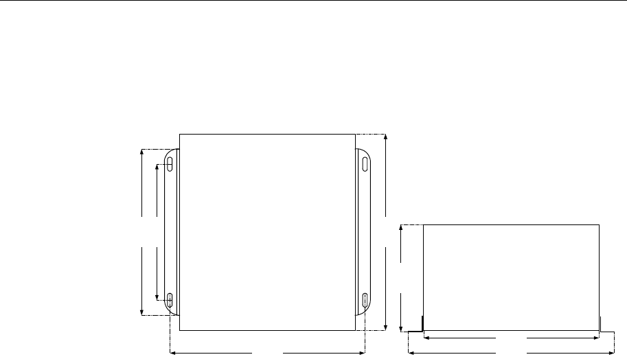
4.3 Physical dimensions
AIS 100 MKD unit
Dimensions: ........................................................................See Figure 4
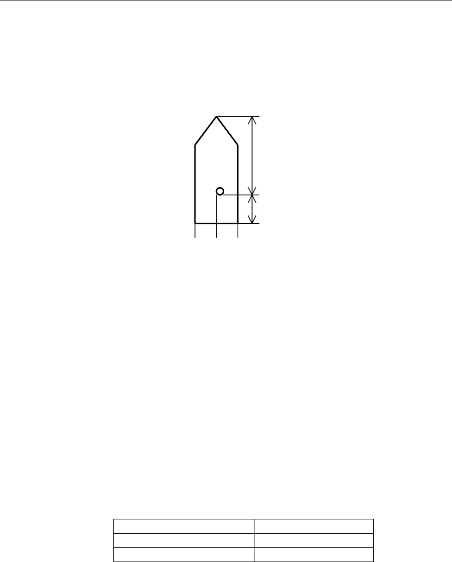
Type:..............................................................Integrated keypad/display
Backlit display and keys:.......................................................Adjustable
Seatex AIS 100 MKD Unit
front view
144mm
252mm
238mm
130mm
37mm
Figure 4 MKD unit dimensions
Seatex AIS 100 Instruction Manual, rev. 5 Technical specifications
28
Mobile station
Dimensions: ........................................................................See Figure 5
Colour: ...................................................................Black NCS S9000-N
Seatex AIS 100 Transponder Unit
front view
Seatex AIS 100 Transponder Unit
top view
190mm
220mm
264mm
230mm
280mm
136mm
257mm
Figure 5 Mobile station dimensions
VHF radio
Number of transmitters:........................................................................1
Number of receivers: ............................................................................3
Channel spacing:.............................................................12.5 or 25 kHz
Frequency range:............................................................ 156 - 165 MHz
Transmitter power:............................2 W or 12 W nominal (selectable)
AIS 1 (Channel 87B): .......................................................161.975 MHz
AIS 2 (Channel 88B): .......................................................162.025 MHz
DSC receiver:....................................................................156.525 MHz
Environmental specifications
Enclosure material: ............................................... Anodised aluminium
Enclosure protection:.......................................................................IP40
Operating temp. range: ..................................................... -15 to +55 ºC
Operating humidity:.............................< 95% relative, non-condensing
Storage temp. range: ......................................................... -15 to +55 ºC
Storage humidity:...................................................................< 60% RH
Vibration:............................ Displacement < 1 mm from 2 Hz to 13 Hz
Vibration: ........................Acceleration < 7 m/s2 from 13 Hz to 100 Hz
GPS receiver
Type:................................................................................ Garmin 25 LP
Operating frequency (reception only):............ 1575.42 MHz ± 10 MHz

Seatex AIS 100 Instruction Manual, rev. 5 Technical specifications
29
AIS 100 connection box
Dimensions: ........................................................................See Figure 6
Voltage input: ............................... 24 V DC (nominal) range 18 – 35 V
Seatex AIS 100 Connection Box
top view
168mm
268mm
110mm
240mm
Ø 6.5mm
100mm
Figure 6 Connection box dimensions
Power
Voltage input: ............................... 24 V DC (nominal) range 18 – 35 V
Power consumption: ................... 50 W peak, approx. 30 W continuous
Batteries:................................................................ No internal batteries
Seatex AIS 100 Instruction Manual, rev. 5 Technical specifications
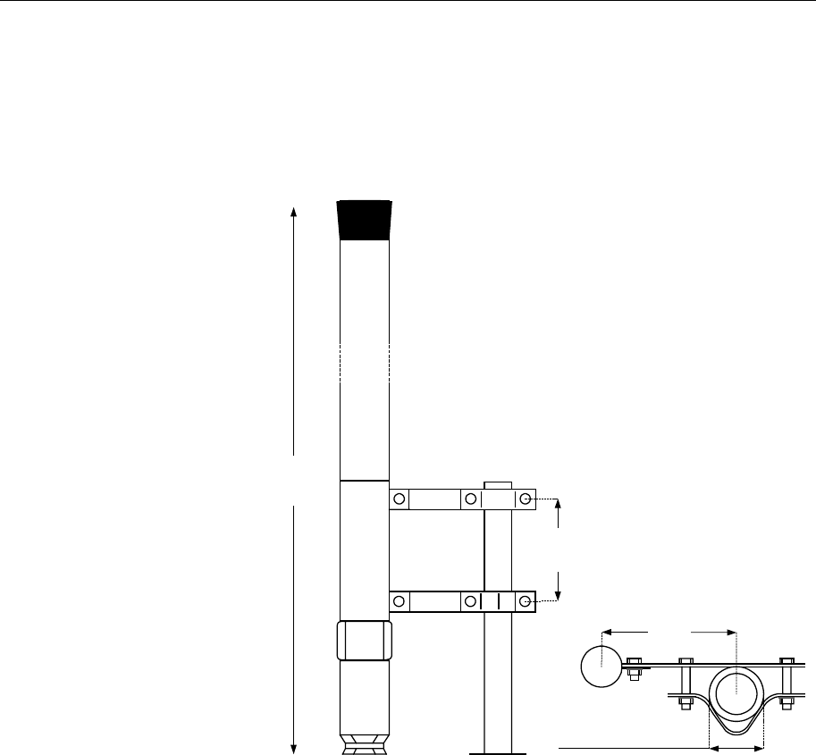
30
VHF antenna
Height: .....................................................................................1400 mm
Weight:....................................................2.2 kg with clamping brackets
Colour: ....................................................... Polyurethane lacquer, white
1400mm
140mm
175mm
Max ø50mm, min ø30mm
Figure 7 VHF antenna
Seatex AIS 100 Instruction Manual, rev. 5 Technical specifications
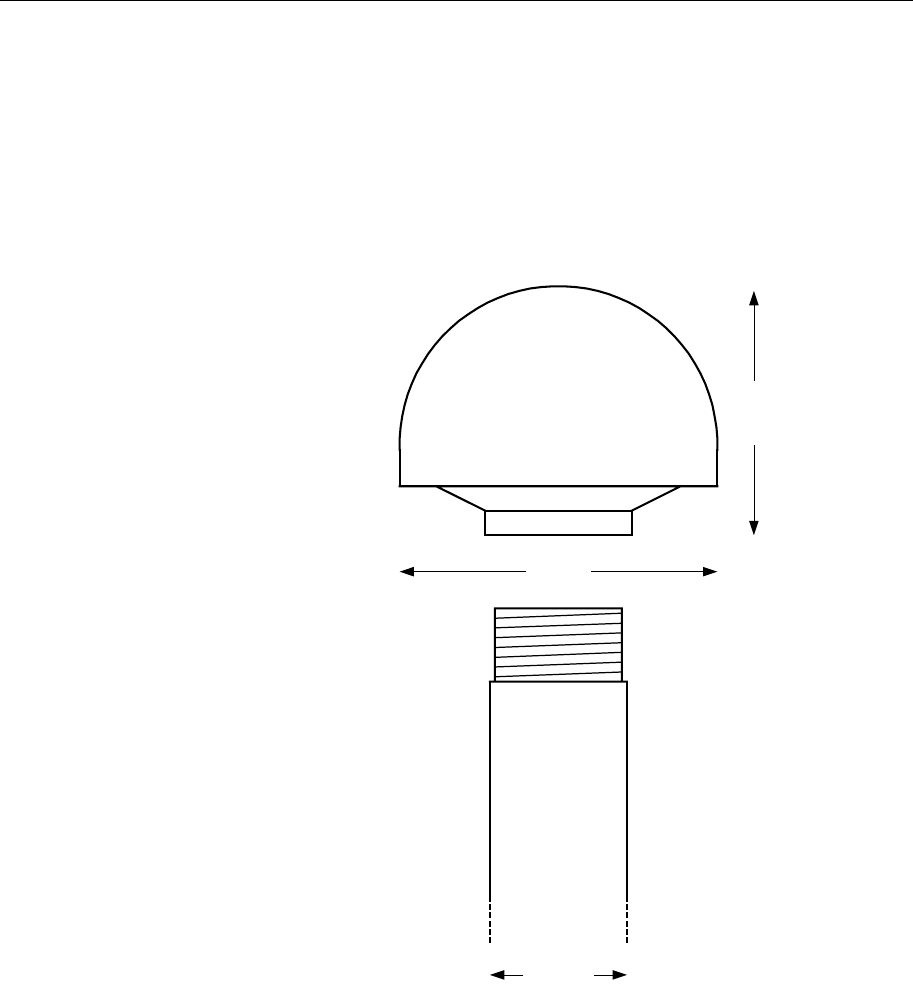
31
GPS antenna
Height: .........................................................................................70 mm
Diameter: .....................................................................................78 mm
Weight:...........................................................................................400 g
Voltage input: ...................................... 5 V DC from the mobile station
24mm
78mm
70mm
Figure 8 GPS antenna and pole dimensions

Seatex AIS 100 Instruction Manual, rev. 5 Technical specifications
32
Blank page

Seatex AIS 100 Instruction Manual, rev. 5 Installation
33
5 INSTALLATION
5.1 General
This section provides detailed information required to install the
Seatex AIS 100 system properly. The installation of the Seatex AIS
100 comprises installation of the components, cable pulling and
termination of interface cables. After connecting the different
components and applying power, the unit needs to be configured
before final tests in order to ensure proper operation of the system.
Unpacking and handling
Care should be taken when unpacking and handling the equipment. A
visual inspection should be made to ensure that the equipment has not
been damaged during shipment and that all parts are present according
to the packing list. A standard scope of supply for a basic Seatex AIS
100 system includes:
• MKD
• Mobile station with cable for connection to the MKD
• Connection box with cable for connection to the mobile station
• GPS antenna
• VHF antenna
Installation distribution
As installation costs may exceed the costs of the mobile station itself,
we recommend that most of the installation is carried out by the vessel
crew. This manual contains detailed installation instructions.
Installations that can be carried out by the vessel
crew:
• Mounting the AIS VHF antenna
• Pulling the VHF cable from the VHF antenna to the mobile station
• Applying connectors to the VHF antenna cable and connecting to
the VHF antenna
• Mounting the AIS GPS antenna
• Pulling the GPS cable from the GPS antenna to the mobile station
• Applying connectors to the GPS antenna cable and connecting to
the GPS antenna
• Mounting the AIS mobile station, the MKD unit and the
connection box
• Connecting the MKD unit to the mobile station using the supplied
cable
• Connecting the connection box to the mobile station using the
supplied cable
• Preparing cable for pilot plug from junction box to pilot location

Seatex AIS 100 Instruction Manual, rev. 5 Installation
34
• Preparing power cable from power source to the connection box
Installations that should be carried out by
authorised personnel:
• Connecting power to the connection box and applying power to
the mobile station
• Providing position interface from the vessel main GPS/GNSS
sensor to the AIS mobile station
• Providing heading interface from the vessel main heading sensor
to the AIS mobile station
• Termination of pilot plug cable in junction box
• Installation of pilot plug
• Providing other interfaces from external sensors to the AIS mobile
station
• Configuring the AIS mobile station
• Verifying that the unit works satisfactory in accordance with the
IMO requirements
In the following you will find detailed descriptions on how to install
the Seatex AIS 100.
5.2 AIS 100 MKD
Typically the MKD unit is installed in a dedicated hole in one of the
bridge consoles or fitted to the bulkhead at a place where the
information easily can be monitored by the navigator. For the physical
installation, screws can be mounted in the four holes hidden behind
the cover on each corner of the unit or used to fasten the bracket
following the MKD. Ensure enough space behind the MKD unit for
connecting the Amphenol connector properly without bending the
cable.
Figure 9 Rear side of the MKD unit and interconnection plug
Seatex AIS 100 Instruction Manual, rev. 5 Installation
35
The connector can be connected to any of the two inputs on the MKD.
The table below gives the pin layout on the display side of the MKD
connector. Amphenol connector type is C091 11H006 801 2 (Male
Crimp contacts are: Amphenol type ZN01 015 0005 (2)).
Signal name D-sub 9-pin ref
(male, crimp) Pair Wire
colour Display
connector
(MKD)
Bus- 7 2 Brown 1
Bus+ 2 2 White 2
V System - 1 1 Black 4
V System + 6 1 White 5
Note! The colour codes are according to Seatex supplied cable.
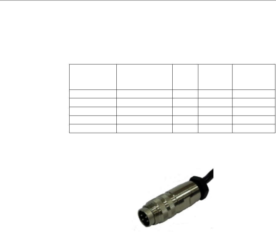
Figure 10 The Amphenol connector
CAUTION! Short circuit on the MKD connector may cause permanent damage
to the mobile station.
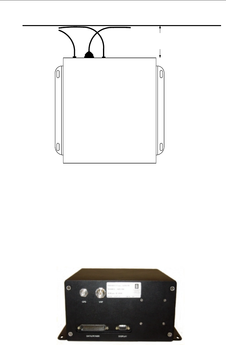
5.3 AIS 100 mobile station
Before installing the mobile station, ensure that the unit will have
proper ventilation and that there is sufficient space at the rear side for
GPS and VHF cable termination as well as the interconnection cable
from the connection box.
Seatex AIS 100 Instruction Manual, rev. 5 Installation
36
Seatex AIS 100 Transponder Unit
Top View
220mm
Recommended minimum
distance from rear side of
connection box to wall.
Interconnection cable
from Connection Box
Bulkhead
GPS and VHF
cable connection
Figure 11 Recommended free space to rear side of mobile station
When installing the mobile station in a rack or onto the
deck/bulkhead, ensure that the unit is properly secured. Clamps are
recommended to be used to secure antenna, power and data cables
connected to the mobile station.
Internal interface connectors
The mobile station interfaces both the MKD and the connection box.
The GPS antenna cable is connected to the rear side of the mobile
station for signal reception to the internal GPS receiver. The VHF
antenna is also connected to the mobile station for VHF signal
reception and transmission.
Figure 12 Rear side of mobile station
Seatex AIS 100 Instruction Manual, rev. 5 Installation
37
The rear panel contains the connectors for interfacing to external
sensors. The table below describes the type and use of the different
connectors.
Connector Type Connected To
Display 9-pin D-Sub male MKD
Data/power 50-pin D-Sub Data/power, internal use
GPS TNC-connector female GPS antenna
VHF N-connector female VHF antenna
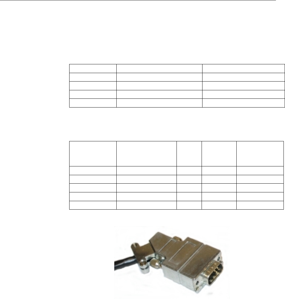
For connecting the MKD unit to the mobile station a D-sub 9 pin
connector is used. The table below shows the wiring of the connector.
Signal name D-sub 9-pin ref
(male, crimp) Pair Wire
colour Display
connector
(MKD)
Bus- 7 1 Brown 1
Bus+ 2 1 White 2
V System - 1 2 Black 4
V System + 6 2 White 5
Figure 13 The 9-pin D-sub plug
5.4 AIS 100 connection box
When installing the connection box, ensure that there is sufficient
space behind the unit so that cable termination from the mobile station
as well as external sensors can be done properly. Fasten the
connection box to the deck or bulkhead.
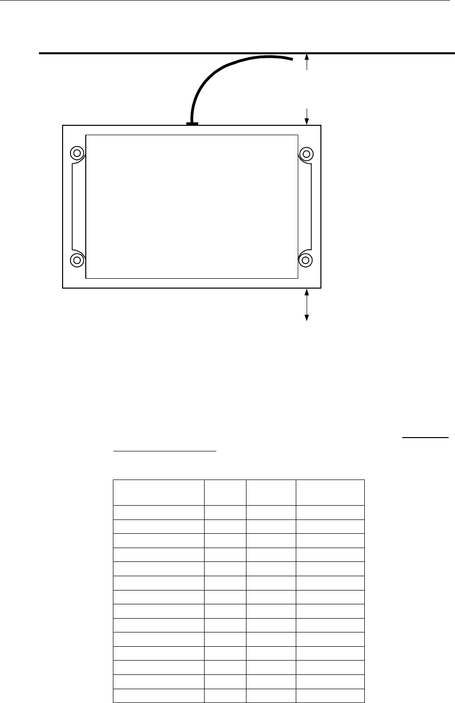
Seatex AIS 100 Instruction Manual, rev. 5 Installation
38
Seatex AIS 100 Connection Box
Top View
125mm
Recommended minimum
distance from rear side of
connection box to wall.
Interconnection cable from
transponder unit.
Ensure sufficient space for external
system interfaces.
Bulkhead
Figure 14 Recommended free space to rear side of connection box
Connection box screw terminals
In the connection box, pins 37 and 38 are connected together, and pins
39 and 40 are connected together with a connection bridge (please
note that the + and GND are paired, so the numbering in the last row:
37, 39, 38 and 40 is correct!). If the power conductors are minimum
one square millimetre, they can be connected to pins 38 and 40 only.
Signal name Pair Wire
colour Connection
box
Pilot_RD(B) 1 Black 1
Pilot_RD(A) 1 Brown 2
Pilot_TD(B) 2 Black 3
Pilot_TD(A) 2 Green 4
Pilot_C 3 Black 5
PI_RD(B) 4 Blue 6
PI_RD(A) 4 Black 7
PI_TD(B) 5 Grey 8
PI_TD(A) 5 Red 9
PI_C 3 Orange 10
LR_RD(B) 6 Brown 11
LR_RD(A) 6 Red 12

Seatex AIS 100 Instruction Manual, rev. 5 Installation
39
Signal name Pair Wire
colour Connection
box
LR_TD(B) 7 Green 13
LR_TD(A) 7 Red 14
LR_C 8 Green 15
Chassis 8 Yellow 36
SENS4_RD(B) 9 Orange 16
SENS4_RD(A) 9 Yellow 17
SENS4_C 10 Blue 18
SENS3_RD(B) 11 Black 19
SENS3_RD(A) 11 Grey 20
SENS3_C 10 Yellow 21
SENS2_RD(B) 12 White 22
SENS2_RD(A) 12 Grey 23
SENS2_C 13 White 24
SENS1_RD(B) 14 Green 25
SENS1_RD(A) 14 White 26
SENS1_C 13 Brown 27
ALM_NC 15 Orange 28
ALM_C 15 White 29
LAN_RX- 16 Blue 30
LAN_RX+ 16 White 31
LAN_TX- 17 Red 32
LAN_TX+ 17 Orange 33
COM1_RXD 18 Red 34
COM1_TXD 18 Blue 35
EXT_GND 19 Brown 37
EXT _24V+ 19 Yellow 39
EXT_GND 20 Black 38
EXT_24V+ 20 Red 40
Seatex AIS 100 Instruction Manual, rev. 5 Installation
40
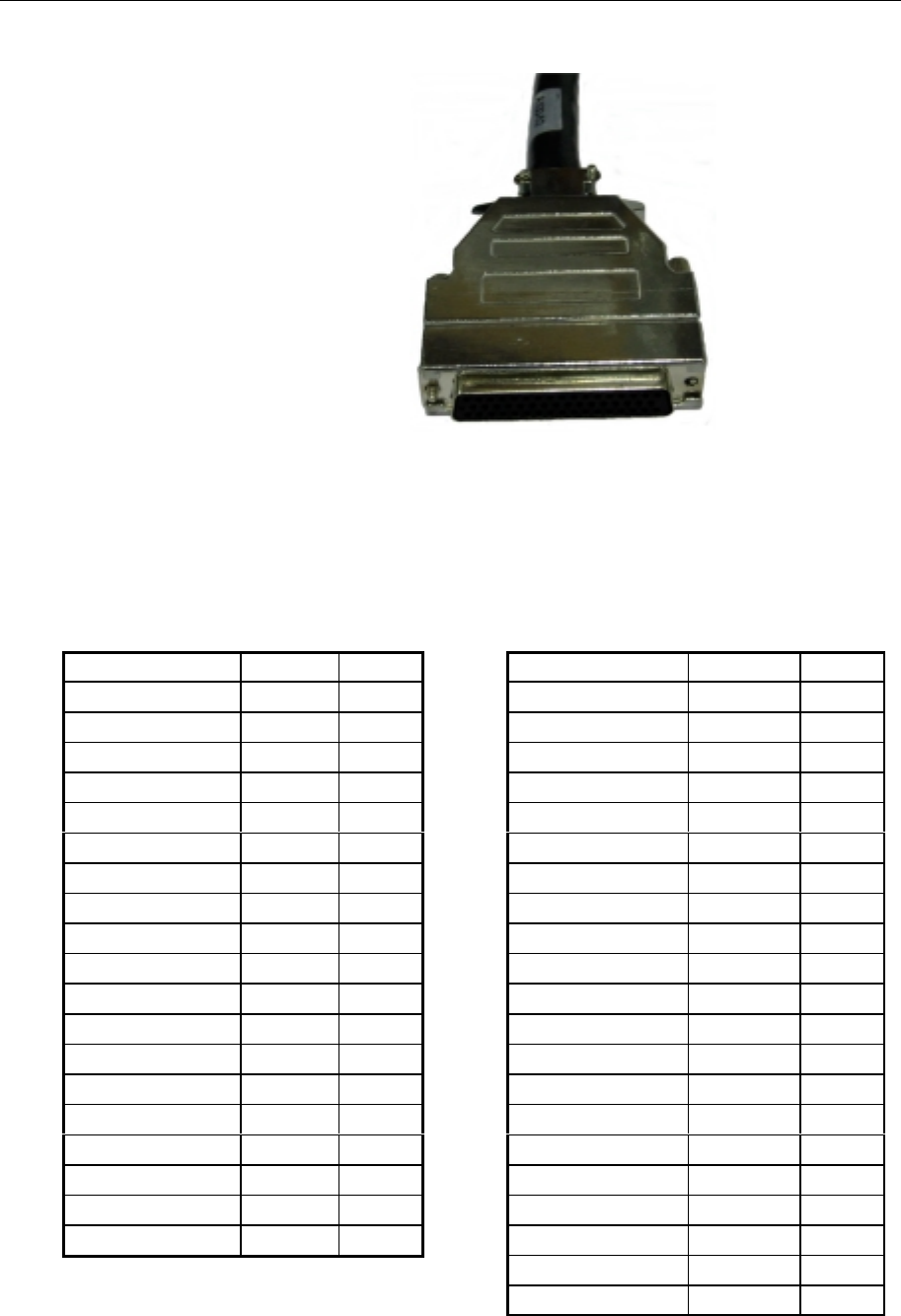
Figure 15 The 50-pin plug
50-pin D-Sub
The data/power connector, which connects to the rear of the AIS 100
Mobile station, is a 50 pin D-Sub female. The pin layout is given in
the table below.
Signal Pin no. Pair Signal Pin no. Pair
Pilot_RD(A) 18 1 SENS3_RD(A) 24 11
Pilot_RD(B) 1 1 SENS3_RD(B) 7 11
Pilot_TD(A) 2 2 SENS3_C 40 10
Pilot_TD(B) 34 2 SENS2_RD(A) 25 12
Pilot_C 19 3 SENS2_RD(B) 8 12
PI_RD(A) 3 4 SENS2_C 41 13
PI_RD(B) 35 4 SENS1_RD(A) 26 14
PI_TD(A) 36 5 SENS1_RD(B) 9 14
PI_TD(B) 20 5 SENS1_C 42 13
PI_C 4 3 ALM_N1 48 15
LR_RD(A) 37 6 ALM_N2 49 15
LR_RD(B) 21 6 LAN_RX- 17 16
LR_TD(A) 22 7 LAN_RX+ 50 16
LR_TD(B) 5 7 LAN_TX- 16 17
LR_C 38 8 LAN_TX+ 33 17
Chassis 10 8 COM1_RXD 27 18
SENS4_RD(A) 23 9 COM1_TXD 43 18
SENS4_RD(B) 6 9 EXT_GND 13 19
SENS4_C 39 10 EXT_24V+ 46 19
EXT_GND 12 20
EXT_24V+ 45 20
Note! RD(A) is low relative to RD(B) when idle.
TD(A) is low relative to TD(B) when idle.
Seatex AIS 100 Instruction Manual, rev. 5 Installation
41
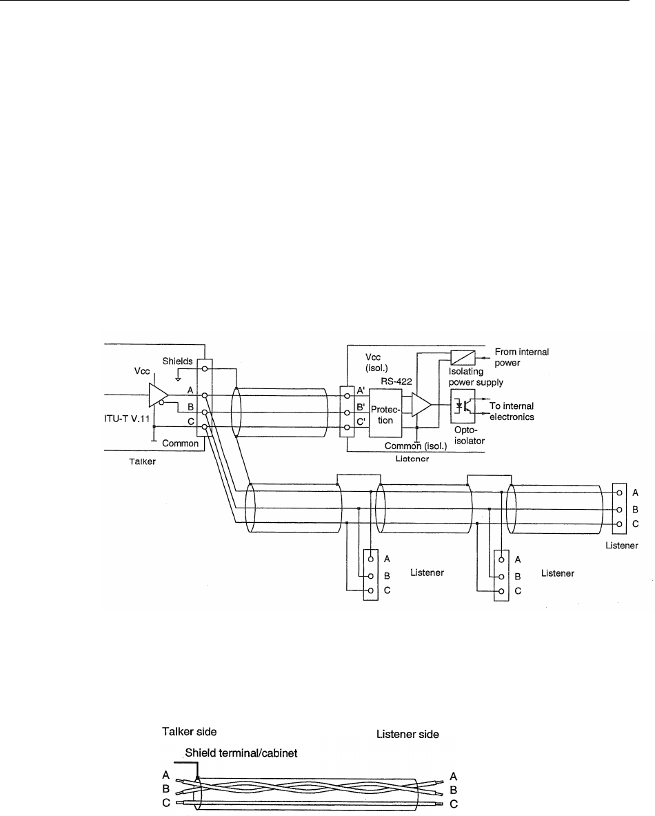
5.5 External cabling of data signals
Shielded twisted pair cables shall be used for the high-speed serial
data ports. The recommended wiring (the figures below are excerpts
from IEC 61162-2, ed. 1) is as shown on the drawings. The A, B and
C designation correspond with the data signals as listed in the tables
on the preceding pages. There may be several listeners (receivers) but
only one talker (transmitter). For long lines we recommend to use a
terminating resistor (120 Ohm between A' and B' at the receiving
end). Avoid stubs or make them as short as possible. The common
wire designated "C" is the signal ground reference and this wire shall
be isolated from the outer shielding. The outer cable shield shall be
continuous (unbroken) through the installation, but shall not be
terminated to any part of the receiver.
Figure 16 Talker and listener cabling – data/shield
Shielded twisted pair cable with third-wire is shown below. The
common "C" wire may be one wire of a pair of another port's common
connection wire "C", if they have the same destination.
Figure 17 Third wire cabling
When the AIS connection box is used, the cable shields will be
continuous from the mobile station to the external installation when
the external cables' shield is properly terminated in the nipples' metal
tongues.
Seatex AIS 100 Instruction Manual, rev. 5 Installation
42
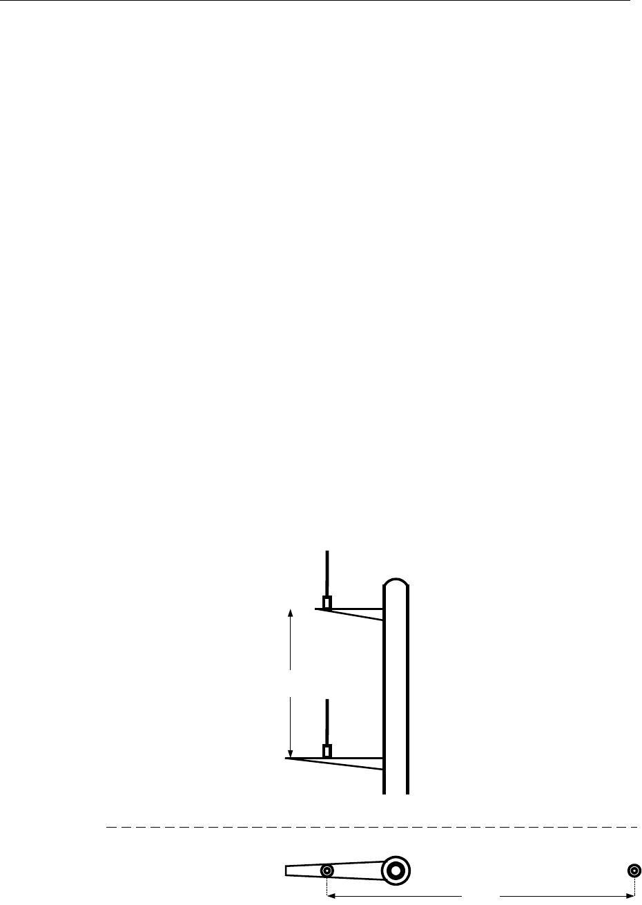
5.6 AIS 100 VHF antenna
The range for receiving VHF signals relates directly to the height of
the antenna above sea level as well as the general on-board conditions
for reception and transmission of radio signals. For optimum AIS
radio performance the following should be taken into consideration:
VHF antenna installation
• It is recommended that the AIS VHF antenna should be placed in a
position with a minimum of 2 metres in horizontal direction from
constructions made of conductive materials.
• The antenna should not be installed close to any large vertical
obstruction and there should be a free view of the horizon through
360 degrees.
• The antenna should be installed safely away from interfering high
power energy sources like radar and other transmitting radio
antennas, preferably at least 3 metres away from and out of the
transmitting beam and there should not be more than one antenna
on the same level.
• The antenna should be mounted directly above or below the ships
primary VHF radiotelephone antenna, with no horizontal
separation and with a minimum of 2 metres vertical separation. If
located on the same level as other antennas, the distance apart
should be at least 10 metres.
Ship radio antenna
AIS VHF antenna
2.0 m
When installed straight above the
ship's radio antenna, the vertical
separation should be 2.0 m
10.0m
Mast
Vertical view
Horisontal view
MastAIS VHF antenna Ship radio antenna
Figure 18 Recommended VHF antenna installation
Seatex AIS 100 Instruction Manual, rev. 5 Installation
43
Antenna cabling
• The cable should be kept as short as possible to minimise
attenuation of the signal. A double shielded coaxial cable equal or
better than RG-214 is recommended.
• All outdoor installed connectors on the coaxial cables should be
fitted with preventive isolation such as shrink stocking with glue
to protect against water penetration into the antenna cable.
• Coaxial cables should not be exposed to sharp bends, which could
change the characteristic impedance of the cable. The minimum
bend radius should be 5 times the cable diameter.
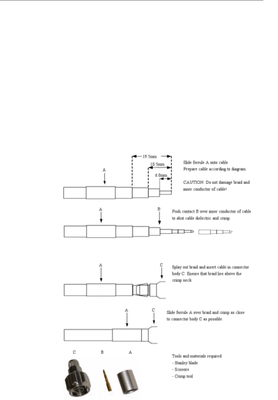
VHF antenna cable connection
The following procedure should be used for proper mounting of cable
connectors:
Figure 19 VHF and GPS antenna cable connector termination
Seatex AIS 100 Instruction Manual, rev. 5 Installation
44
VHF antenna cable lengths
Maximum cable lengths depend on the attenuation factors of the
cables used. The total attenuation of the VHF antenna cables should
be less than 3 dB for proper operation as higher attenuation will
reduce the coverage area of the mobile station. The cable connectors
must be of a type that is designed for the actual cable.
Cable type Max. length
RG214 30 metres
Low loss ½" Superflex 100 metres
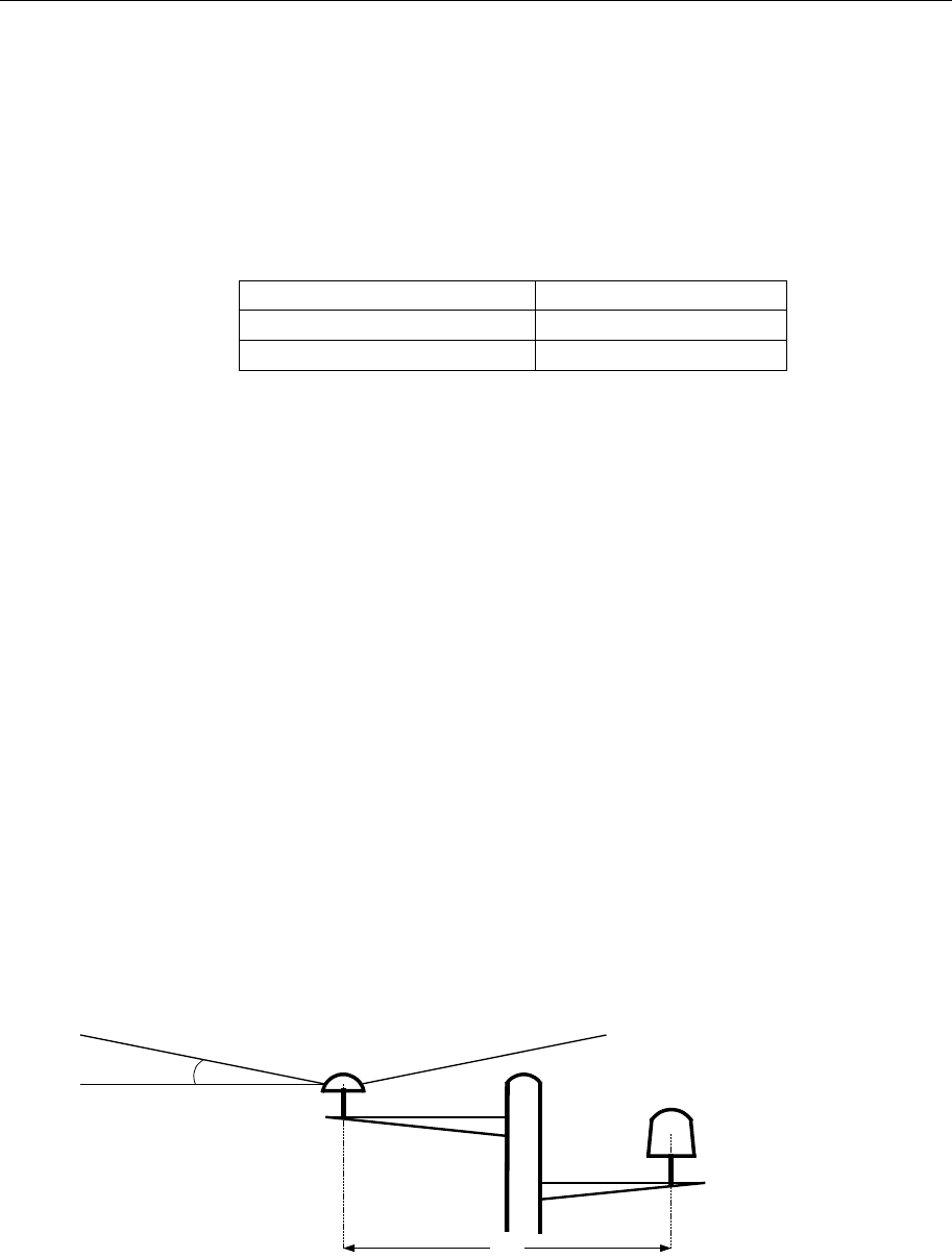
5.7 AIS 100 GPS antenna
GPS antenna installation
Optimum location of the GPS antenna is important to ensure
continuously track of all visible GPS satellites used for time
synchronisation and computation of backup position fix. The
following should be taken into consideration during installation:
• The GPS antenna must be installed where it has a clear view of the
sky and thus the objective is to see the horizon freely through 360
degrees with a vertical observation of 5 to 90 degrees above the
horizon.
• Small diameter obstructions, such as masts and booms, do not
seriously degrade signal reception but such objects must not
eclipse more than a few degrees of any given bearing.
• Locate the antenna at least 3 metres away from and out of the
transmitting beam of high power transmitters (S-band radar and/or
Inmarsat systems). This includes the ship's own AIS VHF antenna
if it is located separately.
High power transmitting
antenna
3.0m
GPS AIS Antenna
10 deg.
Mast
Figure 20 Recommended GPS antenna installation
Seatex AIS 100 Instruction Manual, rev. 5 Installation
45
GPS antenna offset arms
Position data for the GPS antenna needs to be input to the AIS as a
part of the configuration settings. The figure below shows the offset
arms to be configured.
Figure 21 GPS antenna offset arms
GPS antenna cabling
• To achieve optimum performance, the gain of the antenna pre-
amplifier should match the cable attenuation. The resulting
installation gain (pre-amplifier gain – cable attenuation) should be
within 0 to 10 dB.
• The coaxial cable between the antenna and the AIS mobile station
should be routed directly in order to reduce electromagnetic
interference effects.
GPS antenna cable lengths
The GPS antenna cable should have a total attenuation of less than 10
dB as higher attenuation may degrade the quality and accuracy of the
position data.
Cable type Max. length
RG214 30 metres
Low loss ½" Superflex 100 metres
Applying power
After the mechanical and electrical installation is completed the
coaxial cables should be checked for short circuit between centre
conductor and shield (ground) with the antenna disconnected. If not
short-circuited, power could be applied to the mobile station.
A
B
C
D

Seatex AIS 100 Instruction Manual, rev. 5 Installation
46
Sealing of GPS and VHF antenna connectors
• Ensure that the outdoor antenna connectors are wrapped with
waterproof self-vulcanising tape.
• Stretch the tape to double length and start wrapping a bit down on
the cable.
• Wrap the tape all over the connectors and, if possible, seal it with
electric coating.
• An alternate way of waterproofing is to use heat shrinkable hose
with glue.
• The hose should cover the whole connector and part of the cable
and finally it should be sealed with electric coating.
5.8 Internal alarm system
The Seatex AIS 100 has a built-in alarm functionality. The alarm is
generated in different ways:
• Alarm generated by the BIIT.
• Alarm generated by the sensor part.
• Alarm generated by the MKD.
An alarm could cause different actions taken by the system, depending
on the nature of the alarm. An alarm generated by the BIIT could stop
transmission of messages. An alarm will open the alarm relay, which
can be used to trigger an external alarm. There will also be generated
an alarm message on the PI port which can be read on an MKD, if
connected, or on an external interfaced system.
There are two types of alarm messages, which can be output on the PI
and LAN port. An ALM message, e.g. $AIALM, is output when an
error situation arises. A TXT message, e.g. $AITXT, is output when
there is an indicator message. An error situation may arise if there is a
TX malfunction, while an indicator message may arise when
differential corrections are lost. The ALM LED in the front of the AIS
100 will be lit if an error situation arises.
Seatex AIS 100 Instruction Manual, rev. 5 External interfaces
47
6 EXTERNAL INTERFACES
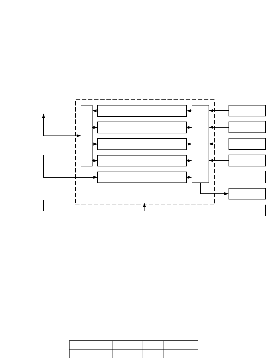
6.1 External interfaces
Increased navigational performance can be achieved by interfacing the
Seatex AIS 100 to an ECDIS, ECS, radar, gyro or heading sensor. All
sensors are connected through the AIS 100 connection box using
serial line communication. This is normally done during installation.
VHF-transmitter
VHF-receive ch. 70
VHF-receive ch. AIS 1
VHF-receive ch. AIS 2
GPS receiver
Interface board
VHF switch
AIS Transponder
GNSS/DGNSS
Antenna
VHF Antenna Heading
GNSS
Rate of Turn
Speed
ECDIS
MKD unit
Figure 22 Interfaces to the Seatex AIS 100 mobile station
6.2 Presentation interface
The presentation interface consists of two physical ports, called PI and
pilot port. The PI port provides a primary port for connection to
onboard equipment such as ECDIS, radar etc. The pilot port provides
a port for connection to the ship's pilot equipment, service equipment,
etc. Both ports are functionally equivalent.
Port configuration
The PI and pilot port have the following default settings:
Baud Rate Parity Bits Stop Bit
38400 N 8 1
The baud rate is configurable to 57600.

Seatex AIS 100 Instruction Manual, rev. 5 External interfaces
48
Input sentences
The AIS is capable of receiving and processing the following IEC
61162-1 sentences on the presentation interface:
Sentence Content
VSD Voyage static data
SSD Ship static data
ABM Addressed binary message
BBM Broadcast binary message
AIR AIS interrogation message
ACA AIS channel assignment command
ACK Acknowledgement message
Proprietary input sentences
The AIS is capable of receiving and processing the following
proprietary IEC 61162-1 sentences on the presentation interface:
Sentence Content
MMSI MMSI number
IMO IMO number
PORT Serial port configuration parameters
Output sentences
The AIS is capable of generating and sending the IEC 61162-1
sentences on the presentation interface:
Sentence Content Transmission interval
ABK Acknowledgement
message Upon reception of
messages 7 and 13, and
when sending message 15
VDO VHF Data link own
message 1 Hz nominal
ALR Alarm messages 30 seconds/1 min.
TXT Indication messages When change of status
ACA AIS channel assignment
command When change of status
VDM VHF Data link message When receiving on VDL
LRI Long-range interrogation When LR request received
& when LR response sent
LRF Long-range function
identification When LR request received
& when LR response sent
LR1 Long-range response When LR response sent
LR2 Long-range response When LR response sent
LR3 Long-range response When LR response sent
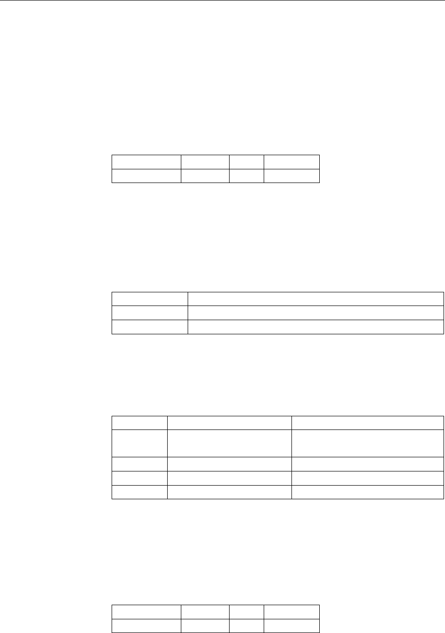
Seatex AIS 100 Instruction Manual, rev. 5 External interfaces
49
6.3 Long range interface
The Long Range interface provides a two-way interface for equipment
that provides for long-range communications, such as Inmarsat.
Port configuration
The Long Range port has the following default settings:
Baud Rate Parity Bits Stop Bit
4800 N 8 1
The baud rate is configurable from 1200 to 57600.
Input sentences
Long Range interrogation of the AIS unit can be accomplished
through use of two IEC 61162-1 sentences.
Sentence Content
LRI Long-range interrogation
LRF Long-range function identification
Output sentences
The Long Range reply from the AIS is accomplished through the use
of four IEC 61162-1 sentences.
Sentence Content Transmission interval
LRF Long-range function
identification When LR response sent
LR1 Long-range response When LR response sent
LR2 Long-range response When LR response sent
LR3 Long-range response When LR response sent
6.4 Sensor input
Port configuration
The sensor inputs Sensor1, Sensor2 and Sensor3 are equivalent and
the default settings are as follows:
Baud Rate Parity Bits Stop Bit
4800 N 8 1
The baud rate is configurable from 1200 to 57600.

Seatex AIS 100 Instruction Manual, rev. 5 External interfaces
50
Input sentences
The following IEC 61162-1 sentences can be received and processed
on each of the three sensor inputs:
Sentence Contents
GGA Position, TOD, position quality (diff/non-diff)
GNS Position, TOD, position quality (diff/non-diff)
GLL Position, TOD, position quality (diff/non-diff)
DTM Datum
VBW SOG, COG (derived from speed components)
VTG SOG, COG
RMC Position, TOD, position quality (diff/non-diff), SOG,
COG
HDT Heading
GBS RAIM indicator
ZDA TOD and Date
OSD Position, TOD, SOG, COG, Heading
ROT Rate of turn
In case the sensor inputs are configured with redundant data, the tables
below describe the priorities of the redundant data.
Priority of Position
Priority Sentence
1RMC
2 GNS
3 GGA
4GLL
Priority of SOG and COG
Priority Sentence
1RMC
2OSD
3VBW
4VTG
Priority of Heading
Priority Sentence
1OSD
2 HDT
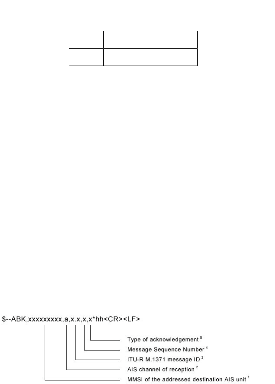
Seatex AIS 100 Instruction Manual, rev. 5 External interfaces
51
Priority of Rate of Turn
Priority Sentence
1ROT
2 OSD (derived from heading)
3 HDT (derived from heading)
6.5 New IEC 61162-1 sentences
This subchapter contains a description of proposed IEC 61162-1
sentences due to AIS. Reference is made to IEC 61193-2, 2001, annex
B2.
ABK – Addressed and binary broadcast
acknowledgement
The ABK-sentence is generated when a transaction, initiated by
reception of an ABM, AIR, or BBM sentence, is completed or
terminated.
This sentence provides information about the success or failure of a
requested ABM broadcast of either ITU-R M.1371 messages 6 or 12.
The ABK process utilises the information received in ITU-R M.1371
messages 7 and 13. Upon reception of either a VHF Data-link
message 7 or 13, or the failure of messages 6 or 12, the AIS unit
delivers the ABK sentence to the external application.
This sentence is also used to report to the external application the AIS
unit's handling of the AIR (ITU-R M.1371 message 15) and BBM
(ITU-R M.1371 messages 8 and 14) sentences. The external
application initiates an interrogation through the use of the AIR-
sentence, or a broadcast through the use of the BBM sentence. The
AIS unit generates an ABK sentence to report the outcome of the AIR
or BBM broadcast process.
NOTE 1 Identifies the distant addressed AIS unit involved with the
acknowledgement. If more than one MMSI are being addressed (ITU-
R M.1371 message 15), the MMSI of the first distant AIS unit,
identified in the message, is the MMSI reported here. When the

Seatex AIS 100 Instruction Manual, rev. 5 External interfaces
52
Message ID is a general broadcast (ITU-R M.1371 messages 8 or 14),
this field is null.
NOTE 2 Indication of VDL channel upon which Message ID 7 or 13
acknowledgement was received. An "A" indicates reception on
channel A. A "B" indicates reception on channel B. If not available,
field is null.
NOTE 3 This indicates to the external application the type of ITU-R M.1371
message that this ABK sentence is addressing. Also see the message
IDs listed in NOTE 4.
NOTE 4 The message sequence number, together with the ITU-R M.1371
message ID and MMSI of the addressed AIS unit, uniquely identifies
a previously received ABM, AIR, or BBM sentence. Generation of an
ABK-sentence makes a sequential message identifier available for
reuse. The ITU-R M.1371 Message ID is used to determine the origin
of the message sequence identifier number. The following table lists
the origins by message ID:
ITU-R M.1371
Message ID Message Sequence Number source
6 sequential message identifier from ABM-
sentence, IEC 61162-1
7 addressed AIS unit's message 7, sequence
number, ITU-R M.1371
8 sequential message identifier from BBM-
sentence, IEC 61162-1
12 sequential message identifier from ABM-
sentence, IEC 61162-1
13 addressed AIS unit's message 13, sequence
number, ITU-R M.1371
14 sequential message identifier from BBM-
sentence, IEC 61162-1
15 no source, field shall be null
NOTE 5 Acknowledgements provided are:
0 = message (6 or 12) successfully received by the addressed
AIS unit,
1 = message (6 or 12) was broadcast, but no
acknowledgement by the distant addressed AIS unit,
3 = message could not be broadcast,
4 = requested broadcast of message (8, 14, or 15) has been
successfully completed, late reception of a message 7 or 13
acknowledgement "addressed to own-ship" MMSI –
identified by; destination MMSI, acknowledgement source
MMSI, message sequence identifier, and message type.
Late reception means that the AIS unit did not have an
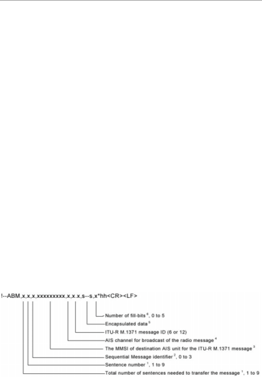
Seatex AIS 100 Instruction Manual, rev. 5 External interfaces
53
acknowledgement process active for the acknowledgement
that was received.
ABM – Addressed Binary and safety related
message
This sentence supports ITU-R M.1371 messages 6 and 12. It provides
an external application with a means to exchange data using an AIS.
The message data is defined by the application only – not the AIS.
This message offers great flexibility for implementing system
functions that use the AIS like a communications device. After
receiving this sentence, the AIS initiates a radio broadcast on the VHF
Data Link (VDL) of either message 6 or 12. The AIS will make up to
four broadcasts of the message. The actual number will depend on the
reception of an acknowledgement from the addressed "destination"
AIS. The default time between retries is 4 s. Retries will not be
attempted more frequently than 4 s. Retries stop when the appropriate
acknowledgement (See ITU-R M.1371 messages 7 and 13.) is
received. The AIS will make up to 4 broadcasts, original broadcast
plus three retires. This process could take 32 s to complete.
The success or failure of the reception of this broadcast by the
intended AIS unit is confirmed through the use of the "Addressed and
binary Broadcast Acknowledgement (ABK)" sentence formatter, and
the processes that support the generation of an ABK-sentence. The
AIS is also limited in the amount of encapsulated data that can be sent
in each slot and frame. If the length of the message would exceed five
slots, or the AIS broadcast would exceed the limit of 20 RATDMA
slot transmissions for the current frame, the AIS will return an ABK-
sentence with an acknowledgement of "2" – message could not be
broadcast.
NOTE 1 The total number of sentences required to transfer the binary message
data to the AIS unit. The first field specifies the total number of
sentences used for a message, minimum value 1. The second field

Seatex AIS 100 Instruction Manual, rev. 5 External interfaces
54
identifies the order of this sentence in the message, minimum value 1.
All sentences contain the same number of fields. Successive sentences
may use null fields for fields that have not changed, such as fields 4,
5, and 6.
NOTE 2 This sequential message identifier serves two purposes. It is both an
IEC 61162-1 "sequential message identifier field," and it is the
"sequence number" utilised by the ITU-R M.1371 in message types 6
and 12. The range of this field is restricted by ITU-R M.1371 to the
range of 0 to 3. This sequential message identifier and the destination
MMSI uniquely identifies a message. The sequential message
identifier may be reused after the "ABK" acknowledgement for that
sequence number is provided by the destination AIS unit. (See the
ABK-sentence formatter.)
NOTE 3 The MMSI of the AIS unit which is the destination of the message.
NOTE 4 The AIS channel that shall be used for the broadcast: 0 = no broadcast
channel preference, 1 = Broadcast on AIS channel A, 2 = Broadcast
on AIS channel B, 3 = Broadcast two copies of the message – one
copy sent on channel A and another copy sent on channel B.
NOTE 5 This is the content of the "binary data" parameter for ITU-R M.1371
message 6, or the "Safety related Text" parameter for message 12. The
first sentence may contain up to 48 "6-bit" symbols (288 bits).
Following sentences may contain up to 60 valid "6-bit" symbols (360
bits), if fields 4, 5, and 6 are unchanged from the first sentence and set
to null. The actual number of "6-bit" symbols in a sentence must be
adjusted so that the total number of characters in a sentence does not
exceed the "82-character" limit.
NOTE 6 To encapsulate, the number of binary bits must be a multiple of six. If
it is not, one to five "fill bits" are added. This parameter indicates the
number of bits that were added to the last 6-bit coded character. This
value shall be set to zero when no "fill bits" have been added. This
cannot be a null field.
ACA – AIS regional channel assignment message
An AIS unit can receive regional channel management information
four ways: ITU-R M.1371 message 22, DSC telecommand received
on channel 70, manual operator input, and an ACA-sentence. The AIS
unit may store channel management information for future use.
Channel management information is applied based upon the actual
location of the AIS unit. An AIS unit is "using" channel management
information when the information is being used to manage the
operation of the VHF receivers and/or transmitter inside the AIS unit.
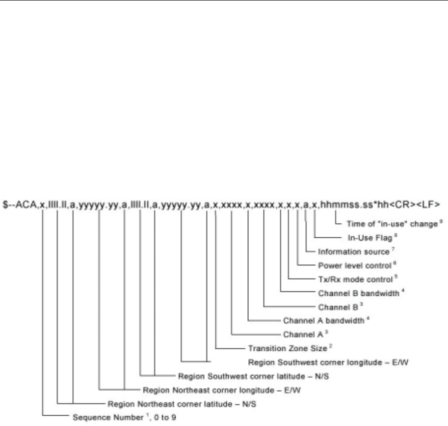
Seatex AIS 100 Instruction Manual, rev. 5 External interfaces
55
This sentence is used to both enter and obtain channel management
information. When sent to an AIS unit, the ACA-sentence provides
regional information that the unit stores and uses to manage the
internal VHF radio. When sent from an AIS unit, the ACA-sentence
provides the current channel management information retained by the
AIS unit. The information contained in this sentence is similar to the
information contained in an ITU-R M.1371 message 22. The
information contained in this sentence directly relates to the
"Initialisation Phase" and "Dual Channel operation and Channel
management" of the AIS unit as described in ITU-R M.1371.
NOTE 1 This is used to bind the contents of the ACA and ACS sentences
together. If provided by the AIS, the ACS sentence shall immediately
follow the related ACA sentence, and both sentences shall contain the
same sequence number. The AIS generating ACA and ACS sentences
shall increment the sequence number by one each time an ACA/ACS
pair is created. After "9" is used, the sequence numbering process
shall begin again from "0". If the sequence numbers do not match, the
information contained in an ACS sentence is not related to the
information in an ACA sentence. The ACS sentence may be used to
respond to an "ACA Query-sentence" (See IEC 61162-1, § 5.3.2.).
The AIS shall respond by providing ACA/ACS pairs for each of the
stored regional operating settings. At any given time, the maximum
number of pairs is eight. When an ACS sentence is not sent following
an ACA sentence, the sequence number may be null.
NOTE 2 Value of 1 nautical mile to a value of 8 nautical miles (with a
resolution of 1 nautical mile)
NOTE 3 VHF channel number, see ITU-R M.1084, Annex 4

Seatex AIS 100 Instruction Manual, rev. 5 External interfaces
56
NOTE 4 Value of 0, bandwidth is specified by channel number, see ITU-R
M.1084, Annex 4
Value of 1, bandwidth is 12,5 kHz.
NOTE 5 Value of 0, transmit on channels A and B, receive on channels A and B
Value of 1, transmit on channel A, receive on channels A and B
Value of 2, transmit on channel B, receive on channels A and B
Value of 3, do not transmit, receive on channels A and B
Value of 4, do not transmit, receive on channel A
Value of 5, do not transmit, receive on channel B
NOTE 6 Value of 0, high power
Value of 1, low power
NOTE 7 Source identifiers:
A, ITU-R M.1371 message 22: Channel Management addressed
message,
B, ITU-R M.1371 message 22: Channel Management broadcast
geographical area message,
C, IEC 61162-1 AIS Channel Assignment sentence,
D, DSC Channel 70 telecommand, and
M, operator manual input.
This field should be null when the sentence is sent to an AIS.
NOTE 8 This value is set to indicate that the other parameters in the sentence
are "in-use" by an AIS unit at the time that the AIS unit sends this
sentence. A value of "0" indicates that the parameters are not "in-use,"
and a value of "1" indicates that the parameters are "in-use." This field
should be null when the sentence is sent to an AIS.
NOTE 9 This is the UTC time that the "in-use" flag changed to the indicated
state. This field should be null when the sentence is sent to an AIS.
AIR – AIS interrogation request
This sentence supports ITU-R M.1371 message 15. It provides an
external application with the means to initiate a request for specific
ITU-R M.1371 messages from distant mobile or base AIS stations. A
single sentence can be used to request, as many as, two messages from
one AIS unit and one message from a second AIS unit. The message
types that can be requested are limited. The complete list of messages
that can be requested can be found within the message 15 description
in ITU-R M.1371. Improper requests may be ignored.
The external application initiates the interrogation. The external
application is responsible for assessing the success or failure of the
interrogation. After receiving this sentence, the AIS initiates a radio
broadcast (on the VHF Data Link) of a message 15 – Interrogation.
The success or failure of the interrogation broadcast is determined by
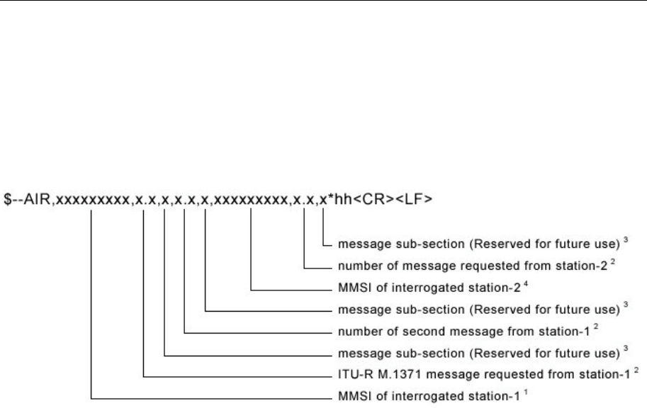
Seatex AIS 100 Instruction Manual, rev. 5 External interfaces
57
the external application's assessment of the combined reception of the
ABK-sentence and future VDM-sentences provided by the AIS via the
Presentation Interface. After receiving this AIR-sentence, the AIS
should broadcast a message 15 within 4 s, and the addressed AIS
should take no more than an additional 4 s to respond – a total of 8 s.
NOTE 1 Identifies the first distant AIS being interrogated. Two messages can
be requested from the first AIS.
NOTE 2 Examples of messages that may be requested from a distant mobile
AIS station include:
Message 3, Position Report,
Message 5, Ship Static and Voyage related data,
Message 9, Standard SAR Aircraft Position Report,
Message 18, Standard Class B Equipment Position Report,
Message 19, Extended Class B Equipment Position Report, and
Message 21, Aids-to-Navigation Report.
Examples of messages that may be requested from a distant AIS base
station include:
Message 4, Base Station Report,
Message 17, GNSS Broadcast Binary Message, (all available
corrections are requested),
Message 20, Data Link Management Message,
Message 22, Channel Management.
NOTE 3 This field is used to request a message that has been further sub-
divided into alternative data structures. When requesting messages
with alternative data structures, this message subsection identifier
must be provided, so that the correct sub-division of the message data
is provided. If the message structure is not sub-divided into different
structures, this field should be null.
NOTE 4 This identifies the second distant AIS being interrogated. Only one
message may be requested from the second AIS. The MMSI of the
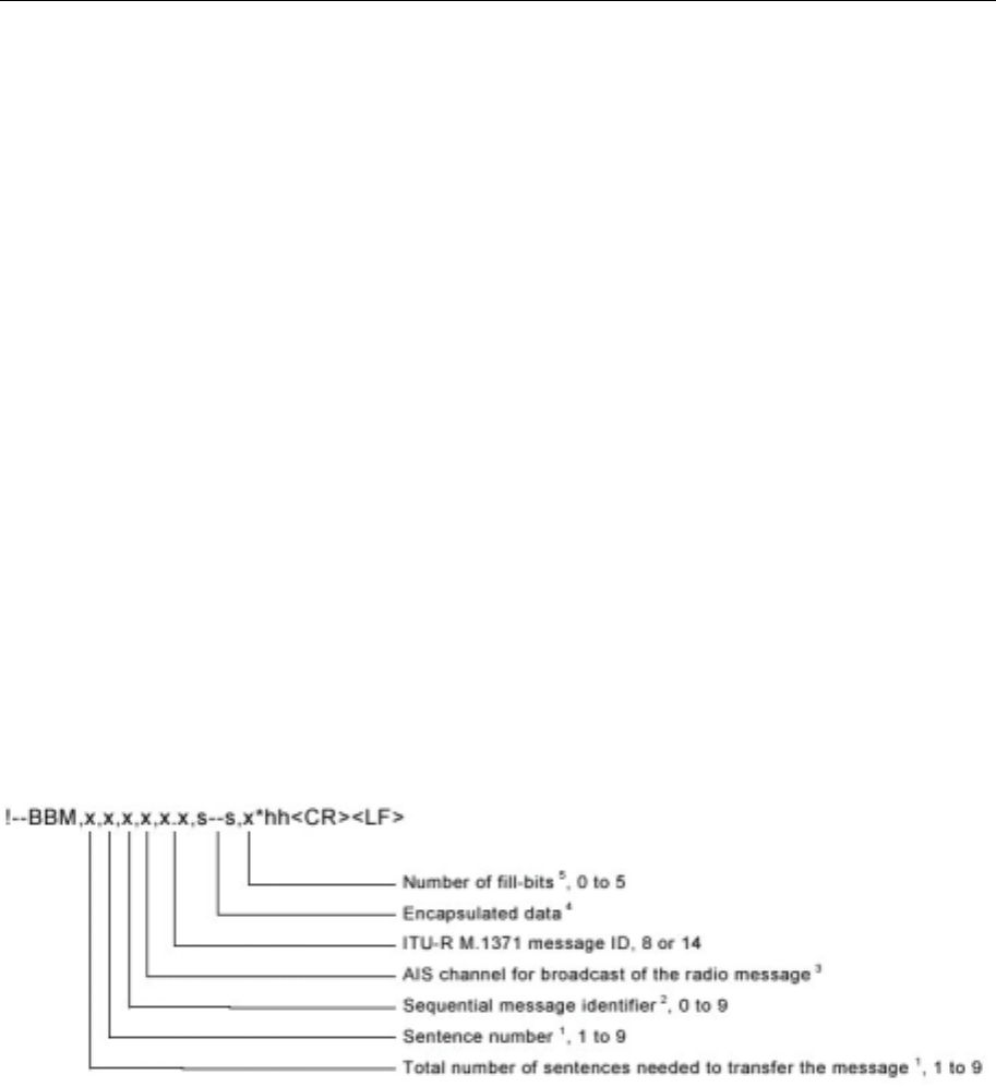
Seatex AIS 100 Instruction Manual, rev. 5 External interfaces
58
second AIS may be the same MMSI as the first AIS. This technique
can be used to request a third message from station-1.
BBM – Broadcast binary message
This sentence supports generation of an ITU-R M.1371 Binary
Broadcast Message (message 8) or Safety Related Broadcast Message
(message 14). It provides an external application with a means to
broadcast data, as defined by the application only – not the AIS. This
message offers great flexibility for implementing system functions
that use the AIS like a digital broadcast device. After receiving this
sentence, the AIS initiates a VHF broadcast of either message 8 or 14
within 4 s. (Also, see the ABK-sentence.)
The success or failure of the broadcast confirmed through the use of
the "Addressed and binary Broadcast Acknowledgement (ABK)"
sentence formatter, and the processes that support the generation of an
ABK-sentence. The AIS is limited in the amount of encapsulated data
that can be sent in each slot and frame. If the length of the message
would exceed five slots, or the AIS broadcast would exceed the limit
of 20 RATDMA slot transmissions for the current frame, the AIS will
return an ABK-sentence
NOTE 1 The total number of IEC 61162-1 sentences needed to transfer the
contents of the binary message to the AIS. The first field specifies the
total number of sentences used for a message, minimum value 1. The
second field identifies the order of this sentence in the message,
minimum value 1. All sentences contain the same number of fields.
Successive sentences may use null fields for fields that do not change
– such as fields 4 and 5.
NOTE 2 The Sequential Message Identifier provides a message identification
number from 0 to 9 that is sequentially assigned as needed. Note that
this is only a sequential message identifier. This is used differently
than the "Message sequence identifier" of an ABM sentence. This
identifier is incremented for each new multi-sentence message. The
count resets to 0, after 9 is used. For the contents of a message 8 or 14
requiring multiple sentences, each sentence of the message contains

Seatex AIS 100 Instruction Manual, rev. 5 External interfaces
59
the same Sequential Message Identification number. This number is
used to link the separate sentences containing portions of the same
encapsulated data. This allows for the possibility that other sentences
might be interleaved with the message sentences that, taken
collectively, contain a single message 8 or 14. This number also links
a future ABK-sentence acknowledgement to the appropriate BBM-
sentence. (See ABK, NOTE 4.)
NOTE 3 The AIS channel that shall be used for the broadcast: 0 = no broadcast
channel preference, 1 = Broadcast on AIS channel A, 2 = Broadcast
on AIS channel B, 3 = Broadcast two copies of the message – one on
channel A and another sent on channel B.
NOTE 4 This is the content of the "binary data" parameter for ITU-R M.1371
message 8 or the "Safety related Text" parameter for message 14. The
first sentence may contain up to 58 "6-bit" symbols (348 bits). The
following sentences may contain up to 60 "6-bit" symbols (360 bits),
if fields 4 and 5 are unchanged from the first sentence and set to null.
The actual number of "6-bit" symbols in a sentence must be adjusted
so that the total number of characters in a sentence does not exceed
the "82-character" limit.
NOTE 5 To encapsulate, the number of binary bits must be a multiple of six. If
it is not, one to five "fill bits" are added. This parameter indicates the
number of bits that were added to the last 6-bit coded character. This
value shall be set to zero when no "fill bits" have been added. This
cannot be a null field.
LRI – Long-Range Interrogation
The long-range interrogation of the AIS is accomplished through the
use of two sentences. The pair of interrogation sentences, a LRI-
sentence followed by a LRF-sentence, provides the information
needed by an AIS to determine if it must construct and provide the
reply sentences (LRF, LR1, LR2, and LR3). The LRI-sentence
contains the information that the AIS needs in order to determine if
the reply sentences need to be constructed. The LRF-sentence
identifies the information that needs to be in the reply sentences.
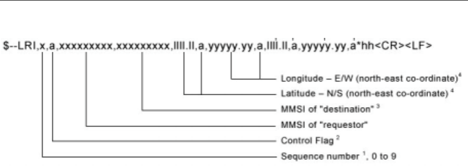
Seatex AIS 100 Instruction Manual, rev. 5 External interfaces
60
NOTE 1 This is used to bind the contents of the LRI and LRF sentences
together. The LRF sentence shall immediately follow the LRI
sentence and use the same sequence number. The requestor process
shall increment the sequence number each time a LRI/LRF pair is
created. The sequencing process shall continuously increment. After
"9" is used, the process shall begin again at "0". If the LRI and LRF
sequence numbers are different, the Long-range interrogation is not
valid.
NOTE 2 The control flag is a single character that qualifies the request for
information. The control flag affects the AIS unit's reply logic. The
control flag cannot be a null field. When the Control Flag is "0", the
AIS responds if either:
The AIS is within the geographic rectangle provided, and
The AIS has not responded to the requesting MMSI in the last
24 hours, and
The MMSI "destination" field is null.
or
The AIS unit's MMSI appears in the MMSI "destination" field
in the LRI sentence.
When the Control Flag is "1", the AIS responds if:
The AIS is within the geographic rectangle provided.
NOTE 3 This is the nine-digit number that uniquely identifies the specific AIS
that should respond. This field is null when the interrogation is for a
geographic region. When addressing a specific AIS, it is not necessary
to provide the geographic co-ordinates of the region.
NOTE 4 The geographic region being interrogated is a "rectangular" area
defined by the latitude and longitude of the north-east and south-west
corners. These fields should be null when interrogating a specific AIS.
(See note 2.)
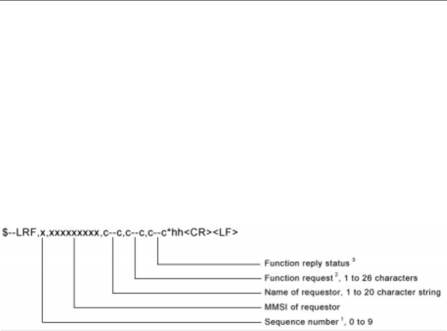
Seatex AIS 100 Instruction Manual, rev. 5 External interfaces
61
LRF – Long Range Function
This sentence is used in both long-range interrogation requests and
long-range interrogation replies. The LRF-sentence is the second
sentence of the long-range interrogation request pair, LRI and LRF
(See the LRI-sentence.). The LRF-sentence is also the first sentence of
the long-range interrogation reply. The minimum reply consists of a
LRF-sentence followed by a LR1-sentence. The LR2-sentence and/or
the LR3-sentence follow the LR1-sentence, if information provided in
these sentences is requested in the interrogation. When the AIS creates
the LRF-sentence for the long-range interrogation reply, fields 1, 2, 3,
and 4 should remain as received in the interrogation; and field 5
(Function Reply Status) and a new checksum are added to the LRF
reply sentence.
NOTE 1 This is used to bind the contents of the LRI and LRF sentences
together. The LRF sentence shall immediately follow the LRI
sentence and use the same sequence number. The requestor process
shall increment the sequence number each time a LRI/LRF pair is
created. After 9 is used, the process shall begin again from 0. The
Long-range interrogation is not valid if the LRI and LRF sequence
numbers are different.
NOTE 2 The Function request field uses alphabetic characters based upon IMO
Resolution A.851(20) to request specific information items. Specific
information items are requested by including their function
identification character in this string of characters. The order in which
the characters appear in the string is not important. All characters are
upper case. Information items will not be provided if they are not
specifically requested – even if available to the AIS. The IMO
Resolution defines the use of all characters from A to Z, but not all of
the defined information is available from the AIS. The following is a
list of the function identification characters with the information they
request:
A = Ship's: name, call sign, and IMO number
B = Date and time of message composition
C = Position
E = Course over ground
F = Speed over ground
I = Destination and Estimated Time of Arrival (ETA)
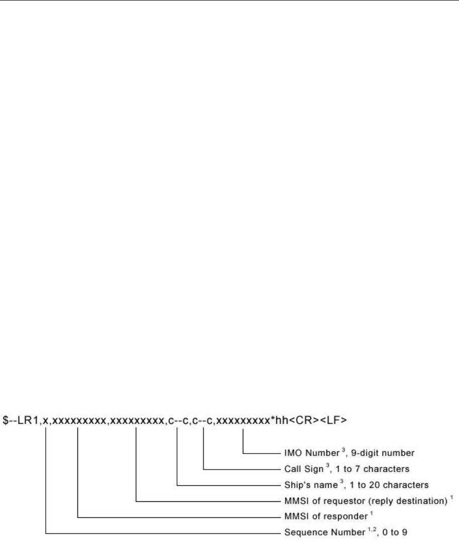
Seatex AIS 100 Instruction Manual, rev. 5 External interfaces
62
O = Draught
P = Ship/Cargo
U = Ship's: length, breadth, type
W = Persons on board
NOTE 3 The "Function Reply Status" field provides the status characters for
the "Function Request" information. When a long-range interrogation
request is originated, the "Function Reply Status" field should be null.
The "Function Reply Status" characters are organised in the same
order as the corresponding function identification characters in the
"Function Request" field. The following is a list of the "Function
Reply Status" characters with the status they represent:
2 = Information available and provided in the following LR1, LR2, or
LR3 sentence,
3 = Information not available from AIS unit,
4 = Information is available but not provided (i.e. restricted access
determined by ship's master),
LR1 – Long-range Reply with destination for
function request "A"
The LR1-sentence identifies the destination for the reply and contains
the information requested by the "A" function identification character.
(See the LRF-sentence.)
NOTE 1 The three fields, sequence number, MMSI of responder, and MMSI of
requestor are always provided.
NOTE 2 The sequence number should be the same number as the sequence
number of the LRI and LRF sentences that initiated this reply.
NOTE 3 The characters that can be used are listed in IEC 61162-1, table 2.
Some characters in this table are the reserved characters listed in IEC
61162-1, table 1. Reserved characters may be used, but they must be
represented using the "^-method" (See IEC 61162-1, § 5.1.3.). The
individual information items shall be a null field, if any one of the
following three conditions exist:

Seatex AIS 100 Instruction Manual, rev. 5 External interfaces
63
The information item was not requested.
The information item was requested, but it is not available.
The information item was requested, but it is not being provided.
LR2 – Long-range Reply for function requests "B,
C, E, and F"
The LR2-sentence contains the information requested by the "B, C, E,
and F" function identification characters. (See the LRF-sentence.)
NOTE 1 If the sentence is used, the two fields, Sequence Number and MMSI of
responder, are always provided.
NOTE 2 The sequence number should be the same number as the sequence
number of the LRI and LRF sentences that initiated this reply.
NOTE 3 The individual information items shall be a null field if any of the
following three conditions exist:
The information item was not requested.
The information item was requested, but it is not available.
The information item was requested, but it is not being provided.
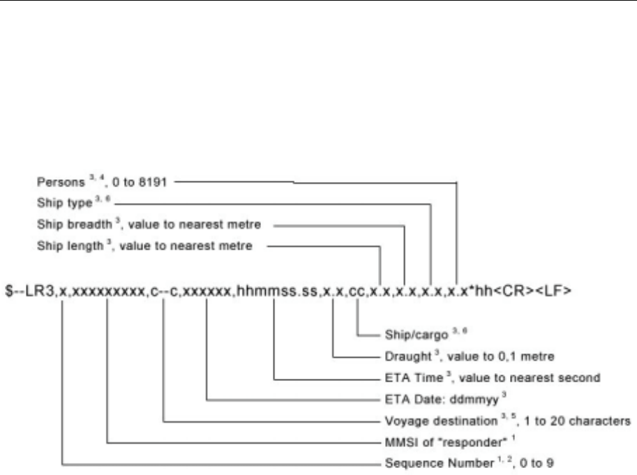
Seatex AIS 100 Instruction Manual, rev. 5 External interfaces
64
LR3 – Long-range Reply for function requests "I,
O, P, U and W"
The LR3-sentence contains the information requested by the "I, O, P,
U, and W" function identification characters (see the LRF-sentence).
NOTE 1 If the sentence is used, the two fields, Sequence Number and MMSI of
responder, are always provided.
NOTE 2 The sequence number should be the same number as the sequence
number of the LRI and LRF sentences that initiated this reply.
NOTE 3 The individual information items shall be a null field if any of the
following three conditions exist:
The information item was not requested,
The information item was requested but is not available, or
The information item was requested but is not being provided.
NOTE 4 Current number of persons on-board, including crew members: 0 to
8191.
0 = default (not available), 8191 = 8191 or more people.
NOTE 5 The characters that can be used are listed in IEC 61162-1, table 2.
Some characters in this table are the reserved characters listed in IEC
61162-1, table 1. Reserved characters may be used, but they must be
represented using the "^-method" (See IEC 61162-1, § 5.1.3.).
NOTE 6 See ITU-R M.1371:2000, table 17, parameter "Type of ship and cargo
type" for the range of valid values available for this field.
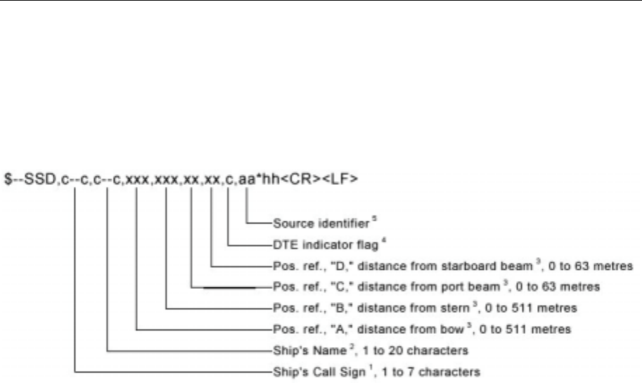
Seatex AIS 100 Instruction Manual, rev. 5 External interfaces
65
SSD – Ship Static Data
This sentence is used to enter static parameters into a shipboard AIS.
The parameters in this sentence support a number of the ITU-R
M.1371 messages.
NOTE 1 Ship call sign. A null field indicates that the previously entered call
sign is unchanged. The string of characters "@@@@@@@" are used
to indicate that the call sign is not available.
NOTE 2 The characters that can be used in the name are listed in the ITU-R
M.1371, table 14 (6-bit ASCII). Some of the acceptable characters in
this 6-bit ASCII table are reserved characters under IEC 61162-1.
They must be represented using the "^-method" (See IEC 61162-1,
section 5.1.3.). A null field indicates that the previously entered name
is unchanged. The string of characters
"@@@@@@@@@@@@@@@@@@@@" are used to indicate
that the ship's name is not available.
NOTE 3 These are the four dimensions from the bow, stern, port beam, and
starboard beam to the horizontal reference point on the ship for which
the current "position reports" are valid. The sum of A + B is the length
of the ship in metres, and the sum of C + D is the width of the ship in
metres (See ITU-R M.1371, message 5, "Reference Point for reported
position and Dimensions of Ship."). If the reference point of "reported
position" is not available, but the dimensions of the ship are available:
A = C = 0 and B > 0 and D > 0. If neither the reference point for the
reported position nor the dimensions of the ship are available: A = B =
C = D = 0 (default). Use of a null field for A, B, C, and/or D indicates
that the previously entered dimension for that parameter is unchanged.
In many cases, the ship's reference point for "reported position" will
be the location of the positioning antenna.
NOTE 4 The DTE indicator is an abbreviation for Data Terminal Equipment
indicator. The purpose of the DTE indicator is to inform distant
receiving applications that, if set to "available" the transmitting station
conforms, at least, to the minimum keyboard and display
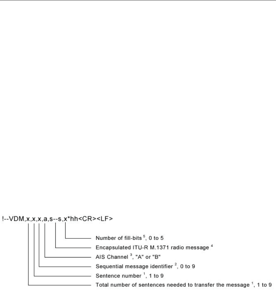
Seatex AIS 100 Instruction Manual, rev. 5 External interfaces
66
requirements. The DTE indicator is only used as information provided
to the application layer – indicating that the transmitting station is
available for communications. On the transmitting side, the DTE
indicator may be set by an external application using this sentence.
DTE indicator flag values are:
0 = Keyboard and display are a standard configuration, and
communication is supported.
1 = Keyboard and display are either unknown or unable to support
communication (default setting).
NOTE 5 The source identifier contains the "Talker ID" of the equipment at this
location. The AIS may use the "Talker ID" to identify multiple
sources of position data and to detect a change to the reference point
on the ship.
VDM – VHF Data-link Message
This sentence is used to transfer the entire contents of a received AIS
message packet, as defined in ITU-R M.1371 and as received on the
VHF Data Link (VDL), using the "6-bit" field type. The structure
provides for the transfer of long binary messages by using multiple
sentences.
NOTE 1 The length of an ITU-R M.1371 message may be long and may
require the use of multiple sentences. The first field specifies the total
number of sentences used for a message, minimum value 1. The
second field identifies the order of this sentence in the message,
minimum value 1. These cannot be null fields.
NOTE 2 The Sequential message identifier provides a message identification
number from 0 to 9 that is sequentially assigned and is incremented
for each new multi-sentence message. The count resets to 0 after 9 is
used. For a message requiring multiple sentences, each sentence of the
message contains the same sequential message identification number.
It is used to identify the sentences containing portions of the same
message. This allows for the possibility that other sentences might be
interleaved with the message sentences that, taken collectively,
contain a single message. This field shall be a null field when
messages fit into one sentence.
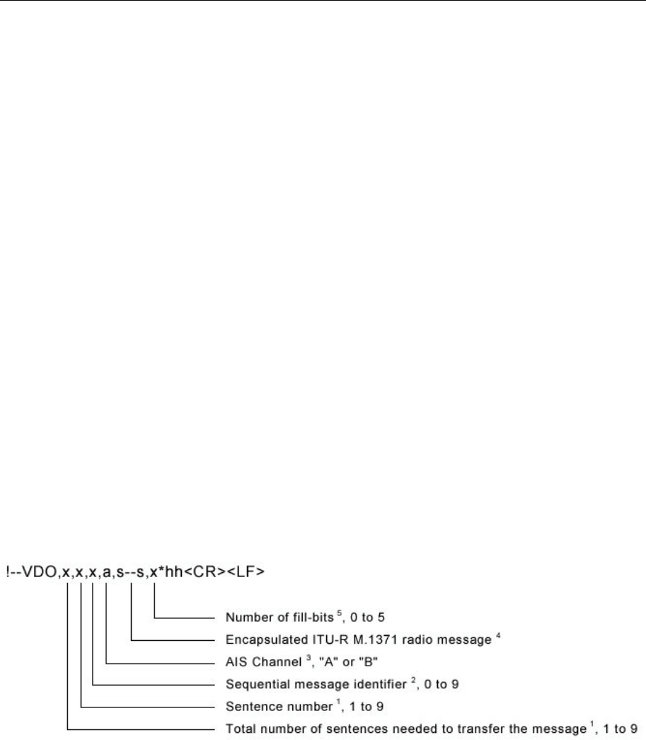
Seatex AIS 100 Instruction Manual, rev. 5 External interfaces
67
NOTE 3 The AIS message reception channel is indicated as either "A" or "B."
This channel indication is relative to the operating conditions of the
AIS when the packet is received. This field shall be null when the
channel identification is not provided. The VHF channel numbers for
channels "A" and "B" are obtained by using an ACA-sentence "query"
of the AIS.
NOTE 4 The maximum string length of encapsulation is limited such that the
total number of sentence characters does not exceed 82. This field
supports a maximum of 62 valid characters for a message transferred
using multiple sentences, and 63 valid characters for a message using
a single sentence.
NOTE 5 To encapsulate, the number of binary bits must be a multiple of six. If
it is not, one to five "fill bits" are added. This parameter indicates the
number of bits that were added to the last 6-bit coded character. This
value shall be set to zero when no "fill bits" have been added. This
cannot be a null field.
VDO – VHF Data-link Own-vessel message
This sentence is used to provide the information assembled for
broadcast by the AIS. It uses the six-bit field type for encapsulation.
The sentence uses the same structure as the VDM sentence formatter.
NOTE 1 The length of an ITU-R M.1371 message may be long and may
require the use of multiple sentences. The first field specifies the total
number of sentences used for a message, minimum value 1. The
second field identifies the order of this sentence in the message,
minimum value 1. These cannot be null fields.
NOTE 2 The Sequential message identifier provides a message identification
number from 0 to 9 that is sequentially assigned and is incremented
for each new multi-sentence message. The count resets to 0 after 9 is
used. For a message requiring multiple sentences, each sentence of the
message contains the same sequential message identification number.
It is used to identify the sentences containing portions of the same
message. This allows for the possibility that other sentences might be
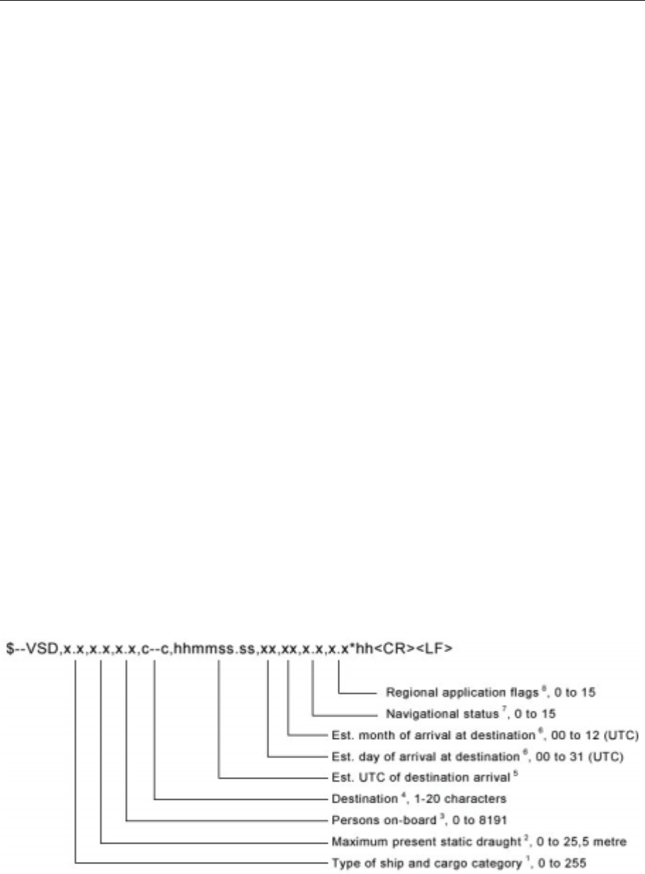
Seatex AIS 100 Instruction Manual, rev. 5 External interfaces
68
interleaved with the message sentences that, taken collectively,
contain a single message. This field shall be a null field when a
message fits into one sentence.
NOTE 3 This is the channel used to broadcast the AIS message. The AIS
channel field, set to either "A" or "B", indicates that the message was
broadcast. If the message is not broadcast, the "AIS Channel" field
shall be null. The VHF channel numbers for channels "A" and "B" are
obtained by using an ACA-sentence "query" of the AIS.
NOTE 4 The maximum string length of encapsulation is limited such that the
total number of sentence characters does not exceed 82. This field
supports a maximum of 62 valid characters for a message transferred
using multiple sentences, and 63 valid characters for a message using
a single sentence.
NOTE 5 To encapsulate, the number of binary bits must be a multiple of six. If
it is not, one to five "fill bits" are added. This parameter indicates the
number of bits that were added to the last 6-bit coded character. This
value shall be set to zero when no "fill bits" have been added. This
cannot be a null field.
VSD – Voyage Static Data
This sentence is used to enter information about a ship's voyage. This
information remains relatively static during the voyage. However, the
information will frequently change from voyage to voyage. The
parameters in this sentence support a number of the ITU-R M.1371
messages.
NOTE 1 Type of ship and cargo category are defined in ITU-R M.1371. The
description of ship and cargo are indicated by a number. The values
are defined in ITU-R M.1371, message 5. A null field indicates that
this is unchanged.

Seatex AIS 100 Instruction Manual, rev. 5 External interfaces
69
NOTE 2 Draught is reported in the range of 0 to 25,5 metres. The value 0 = not
available (default), and the value 25,5 indicates that the draught is
25,5 metres or more. Only values from 0 to 25,5 shall be accepted by
the AIS. A null field indicates that this is unchanged.
NOTE 3 Number of persons on-board includes the crew. The value 0 = not
available (default). The value 8191 = 8191 or more people. Only
values from 0 to 8191 shall be accepted by the AIS. A null field
indicates that this is unchanged.
NOTE 4 The characters that can be used in the destination are listed in the ITU-
R M.1371, table 14 (6-bit ASCII). Some of the acceptable characters
in this 6-bit ASCII table are reserved characters under IEC 61162-1.
They must be represented using the "^-method" (See IEC 61162-1,
section 5.1.3.). A null field indicates that the previously entered
destination is unchanged. The string of characters
"@@@@@@@@@@@@@@@@@@@@" are used to indicate
that the ship's destination is not available.
NOTE 5 The UTC time of arrival field follows the "TIME" field type described
in table 6 (IEC 61162-1). The two fixed digits of seconds are not
broadcast by the AIS and should be set to "00". The optional decimal
point and associated decimal fraction shall not be provided. The
resulting time is a number with six fixed digits, "hhmm00". Leading
zeros are always included for the hours and minutes. If the hour of
arrival is not available, "hh" shall be set to 24. If the minute of arrival
is not available, "mm" shall be set to 60. A null field indicates that this
is unchanged.
NOTE 6 The day and month of arrival are in UTC. The day is a two-digit fixed
number requiring leading zeros. The month is a two-digit fixed
number requiring leading zeros. If the day of arrival is not available,
"00" shall be the number for day. If the month of arrival is not
available, "00" shall be the number for the month. A null field
indicates that this is unchanged.
NOTE 7 The Navigational status is indicated using the following values, a null
field indicates the status is unchanged (ref. ITU-R M.1371, Message
1, Navigational status parameter):
0 = under way using engine
1 = at anchor
2 = not under command
3 = restricted manoeuvrability
4 = constrained by draught
5 = moored
6 = aground
7 = engaged in fishing
8 = under way sailing
9 = reserved for High Speed Craft
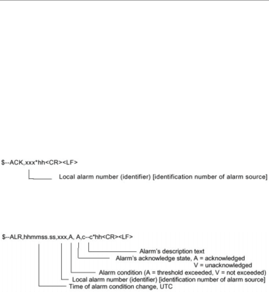
Seatex AIS 100 Instruction Manual, rev. 5 External interfaces
70
10 = reserved for Wing In Ground
11 to 14 = reserved for future use
15 = not defined (default)
NOTE 8 Definition of values 1 to 15 provided by a competent regional
authority. Value shall be set to zero (0), if not used for any regional
application. Regional applications shall not use zero. A null field
indicates that this is unchanged (ref. ITU-R M.1371, Message 1,
Reserved for regional applications parameter).
6.6 IEC 61162-1, Ed. 2, sentences
ACK – Acknowledge alarm
Acknowledge device alarm. This sentence is used to acknowledge an
alarm condition reported by a device.
ALR – Set alarm state
Local alarm condition and status. This sentence is used to report an
alarm condition on a device and its current state of acknowledgement.
DTM - Datum reference
Local geodetic datum and datum offsets from a reference datum. This
sentence is used to define the datum to which a position location, and
geographic locations in subsequent sentences, are referenced.
Latitude, longitude and altitude offsets from the reference datum, and
the selection of the reference datum, are also provided.
Cautionary notes: The datum sentence should be transmitted
immediately prior to every positional sentence (e.g. GLL, BWC, WPL)
which is referenced to a datum other than WGS84, the datum
recommended by IMO.
For all datums the DTM sentence should be transmitted prior to any
datum change and periodically at intervals of not greater than 30 s.
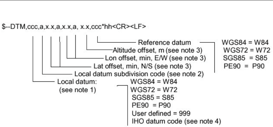
Seatex AIS 100 Instruction Manual, rev. 5 External interfaces
71
NOTE 1 Three character alpha code for local datum. If not one of the listed
earth-centred datums, or 999 for user defined datums, use IHO datum
code from International Hydrographic Organisation Publication S-60,
Appendices B and C. Null field if unknown.
NOTE 2 One character subdivision datum code when available or user defined
reference character for user defined datums, null field otherwise.
Subdivision character from IHO Publication S-60, Appendices B and
C.
NOTE 3 Latitude and longitude offsets are positive numbers, the altitude offset
may be negative. Offsets change with position: position in the local
datum is offset from the position in the reference datum in the
directions indicated:
Plocal datum = Pref datum + offset
NOTE 4 Users should be aware that chart transformations based on IHO S60
parameters may result in significant positional errors when applied to
chart data.
Only the local datum is required and used by the AIS.
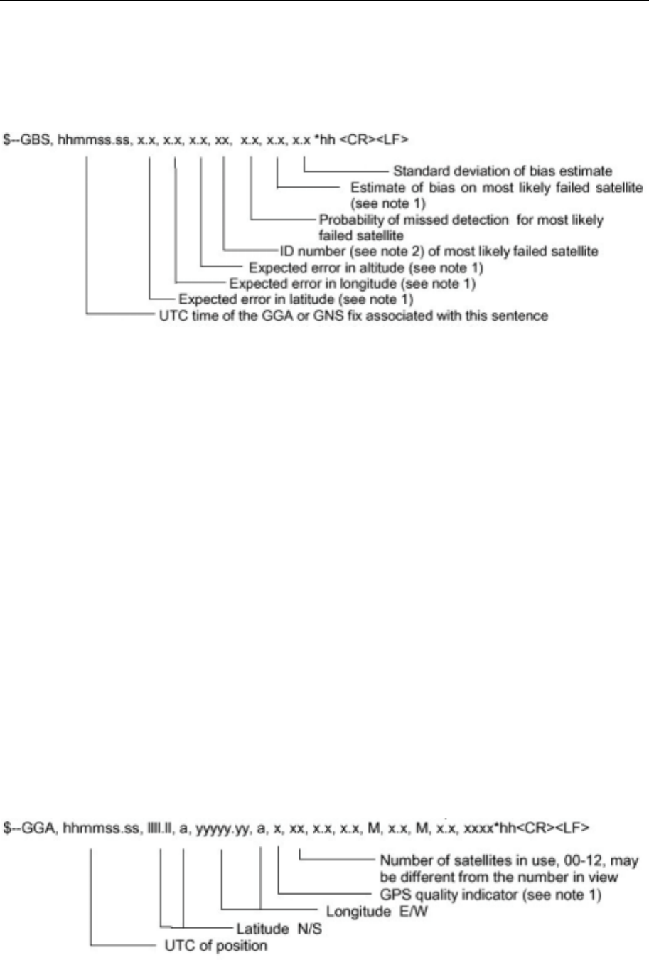
Seatex AIS 100 Instruction Manual, rev. 5 External interfaces
72
GBS – GNSS satellite fault detection
This message is used for setting the RAIM flag in the position reports
sent by the AIS.
NOTE 1 Expected error in metres due to bias, with noise = 0.
NOTE 2 Satellite ID numbers. To avoid possible confusion caused by
repetition of satellite ID numbers when using multiple satellite
systems, the following convention has been adopted:
a) GPS satellites are identified by their PRN numbers, which range
from 1 to 32.
b) The WAAS system has reserved numbers 33 – 64 to identify its
satellites.
c) The numbers 65 – 96 are reserved for GLONASS satellites.
GLONASS satellites are identified by 64+ satellite slot numbers.
The slot numbers are 1 through 24 for the full GLONASS
constellation of 24 satellites, thus giving a range of 65 through 88.
The numbers 89 through 96 are available if slot numbers above 24
are allocated to on-orbit spares.
Only Expected error in latitude and Expected error in longitude is
required and used by the AIS.
GGA – Global positioning system (GPS) fix data
Time, position and fix-related data for a GPS receiver.
NOTE 1 GPS quality indicator:
0 = fix not available or invalid
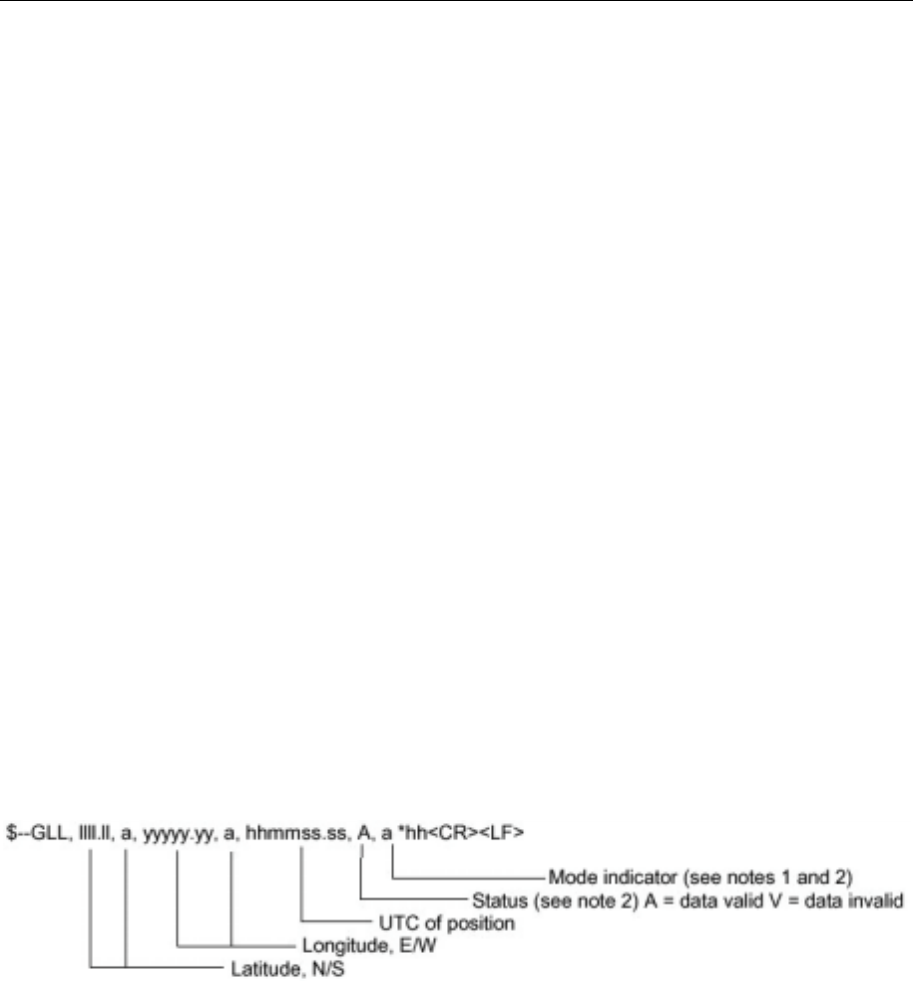
Seatex AIS 100 Instruction Manual, rev. 5 External interfaces
73
1 = GPS SPS mode, fix valid
2 = differential GPS, SPS mode, fix valid
3 = GPS PPS mode, fix valid
4 = Real Time Kinematic. Satellite system used in RTK mode with
fixed integers
5 = Float RTK. Satellite system used in RTK mode with floating
integers
6 = Estimated (dead reckoning) mode
7 = Manual input mode
8 = Simulator mode
The GPS Quality Indicator shall not be a null field.
NOTE 2 Time in seconds since last SC104 type 1 or 9 update, null field when
DGPS is not used.
NOTE 3 Geoidal separation: the difference between the WGS-84 earth
ellipsoid surface and mean sea level (geoid) surface, " – " = mean sea
level surface below the WGS-84 ellipsoid surface.
Utc of position, Latitude, Longitude and GPS quality is the only fields
that are used by the AIS.
GLL – Geographic position – latitude/longitude
Latitude and longitude of vessel position, time of position fix and
status.
NOTE 1 Positioning system Mode indicator:
A = Autonomous
D = Differential
E = Estimated (dead reckoning)
M = Manual input
S = Simulator
N = Data not valid
NOTE 2 The Mode Indicator field supplements the Status field (field 6). The
Status field shall be set to V = invalid for all values of Operating
Mode except for A = Autonomous and D = Differential. The
positioning system Mode indicator and Status fields shall not be null
fields.
All fields are used by the AIS.
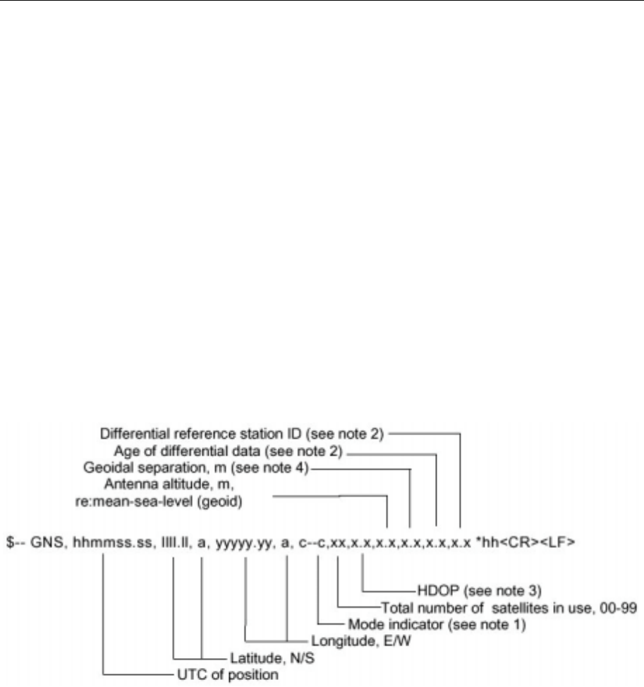
Seatex AIS 100 Instruction Manual, rev. 5 External interfaces
74
GNS – GNSS fix data
Fix data for single or combined satellite navigation systems (GNSS).
This sentence provides fix data for GPS, GLONASS, possible future
satellite systems and systems combining these. This sentence could be
used with the talker identification of GP for GPS, GL for GLONASS,
GN for GNSS combined systems, as well as future identifiers. Some
fields may be null fields for certain applications, as described below.
If a GNSS receiver is capable simultaneously of producing a position
using combined satellite systems, as well as a position using only one
of the satellite systems, then separate $GPGNS, $GLGNS, etc.
messages may be used to report the data calculated from the
individual systems.
If a GNSS receiver is set up to use more than one satellite system, but
for some reason one or more of the systems are not available, then it
may continue to report the positions using $GNGNS, and use the
mode indicator to show which satellite systems are being used.
NOTE 1 Mode Indicator. A variable length valid character field type with the
first two characters currently defined. The first character indicates the
use of GPS satellites, the second character indicates the use of
GLONASS satellites. If another satellite system is added to the
standard, the mode indicator will be extended to three characters; new
satellite systems shall always be added to the right, so the order of
characters in the Mode Indicator is: GPS, GLONASS, other satellite
systems.
The characters shall take one of the following values:
N = No fix. Satellite system not used in position fix, or fix not valid.
A = Autonomous.Satellite system used in non-differential mode in
position fix.
D = Differential. Satellite system used in differential mode in position
fix.

Seatex AIS 100 Instruction Manual, rev. 5 External interfaces
75
P = Precise. Satellite system used in precision mode. Precision mode
is defined as: no deliberate degradation (such as Selective
Availability), and higher resolution code (P-code) is used to compute
position fix.
R = Real Time Kinematic. Satellite system used in RTK mode with
fixed integers.
F = Float RTK. Satellite system used in real time kinematic mode with
floating integers.
E = Estimated (dead reckoning) Mode.
M = Manual Input Mode.
S = Simulator Mode.
The Mode indicator shall not be a null field.
NOTE 2 Age of differential data and Differential reference station ID
a) When the talker is GN and more than one of the satellite systems
are used in differential mode, then the "Age of differential data"
and "Differential reference station ID" fields shall be null. In this
case, the "Age of differential data" and "Differential reference
station ID" fields shall be provided in following GNS messages
with talker IDs of GP,GL, etc. These following GNS messages
shall have the latitude, N/S, longitude, E/W, altitude, geoidal
separation, mode and HDOP fields null. This indicates to the
listener that the field is supporting a previous $GNGNS message
with the same time tag. The "Number of satellites" field may be
used in these following messages to denote the number of
satellites used from that satellite system.
Example: A combined GPS/GLONASS receiver using only GPS differential
corrections has the following GNS sentence sent:
$GNGNS,122310.2,3722.425671,N,12258.856215,W,DA,14,0.9,1005
.543,6.5,5.2,23*59<CR><LF>
Example: A combined GPS/GLONASS receiver using both GPS differential
corrections and GLONASS differential corrections may have the
following three GNS sentences sent in a group:
$GNGNS,122310.2,3722.425671,N,12258.856215,W,DD,14,0.9,1005
.543,6.5,,*74<CR><LF>
$GPGNS,122310.2, , , , , , 7, , , ,5.2,23*4D<CR><LF>
$GLGNS,122310.2, , , , , , 7, , , ,3.0,23*55<CR><LF>
The Differential Reference station ID may be the same or different for
the different satellite systems
b) Age of Differential Data

Seatex AIS 100 Instruction Manual, rev. 5 External interfaces
76
For GPS differential data: This value is the average of the most
recent differential corrections in use. When only RTCM SC104 Type
1 corrections are used, the age is that of the most recent Type 1
correction. When RTCM SC104 Type 9 corrections are used solely, or
in combination with Type 1 corrections, the age is the average of the
most recent corrections for the satellites used. Null field when
Differential GPS is not used.
For GLONASS differential data: This value is the average age of
the most recent differential corrections in use. When only RTCM
SC104 Type 31 corrections are used, the age is that of the most recent
Type 31 correction. When RTCM SC104 Type 34 corrections are
used solely, or in combination with Type 31 corrections, the age is the
average of the most recent corrections for the satellites used. Null field
when differential GLONASS is not used.
NOTE 3 HDOP calculated using all the satellites (GPS, GLONASS and any
future satellites) used in computing the solution reported in each GNS
sentence.
NOTE 4 Geoidal separation is the difference between the earth ellipsoid
surface and mean-sea-level (geoid) surface defined by the reference
datum used in the position solution, "-" = mean-sea-level surface
below ellipsoid surface. The reference datum may be specified in the
DTM sentence.
UTC of position, Latitude, Longitude and Mode indicator, are the only
fields used by the AIS.
HDT – Heading true
IMO Resolutions A.424 and A.821. Actual vessel heading in degrees
true produced by any device or system producing true heading.
All fields are used by the AIS.
OSD Own ship data
IMO Resolution A.477 and MSC 64(67), Annex 1 and Annex 3.
Heading, course, speed, set and drift summary. Useful for, but not
limited to radar/ARPA applications. OSD gives the movement vector
of the ship based on the sensors and parameters in use.
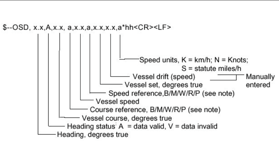
Seatex AIS 100 Instruction Manual, rev. 5 External interfaces
77
NOTE Reference systems on which the calculation of vessel course and
speed is based. The values of course and speed are derived directly
from the referenced system and do not additionally include the effects
of data in the set and drift fields.
B = bottom tracking log
M = manually entered
W = water referenced
R = radar tracking (of fixed target)
P = positioning system ground reference.
Heading, Heading status, Vessel course, Vessel speed and Speed
units, are used by the AIS.
RMC - Recommended minimum specific GNSS
data
Time, date, position, course and speed data provided by a GNSS
navigation receiver. This sentence is transmitted at intervals not
exceeding 2 s and is always accompanied by RMB when a destination
waypoint is active. RMC and RMB are the recommended minimum
data to be provided by a GNSS receiver. All data fields must be
provided null fields used only when data is temporarily unavailable.
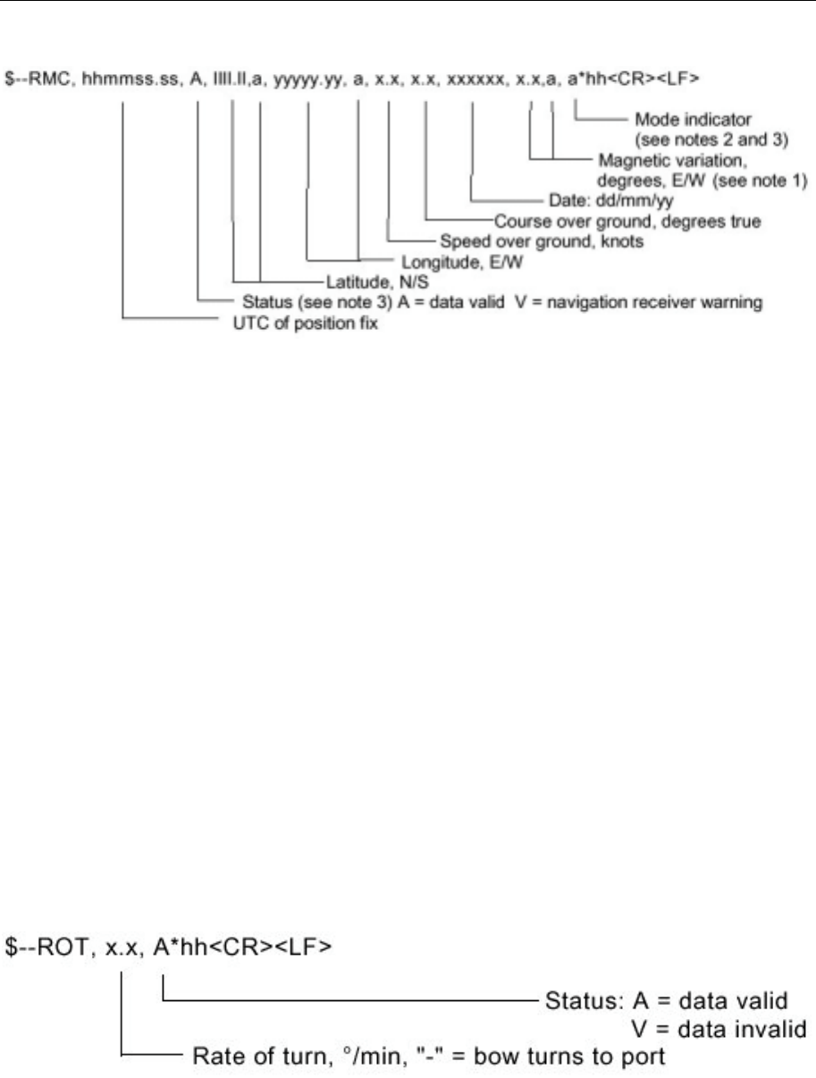
Seatex AIS 100 Instruction Manual, rev. 5 External interfaces
78
NOTE 1 Easterly variation (E) subtracts from true course. Westerly variation
(W) adds to true course.
NOTE 2 Positioning system Mode indicator:
A = Autonomous mode
D = Differential mode
E = Estimated (dead reckoning) mode
M = Manual input mode
S = Simulator mode
N = Data not valid
NOTE 3 The positioning system Mode indicator field supplements the
positioning system Status field (field No. 2) which shall be set to V =
invalid for all values of Mode indicator except for A = Autonomous
and D = Differential. The positioning system Mode indicator and
Status fields shall not be null fields.
All fields, except Magnetic variation is used by the AIS.
ROT – Rate of turn
IMO Resolution A.526. Rate of turn and direction of turn.
All fields are used by the AIS.
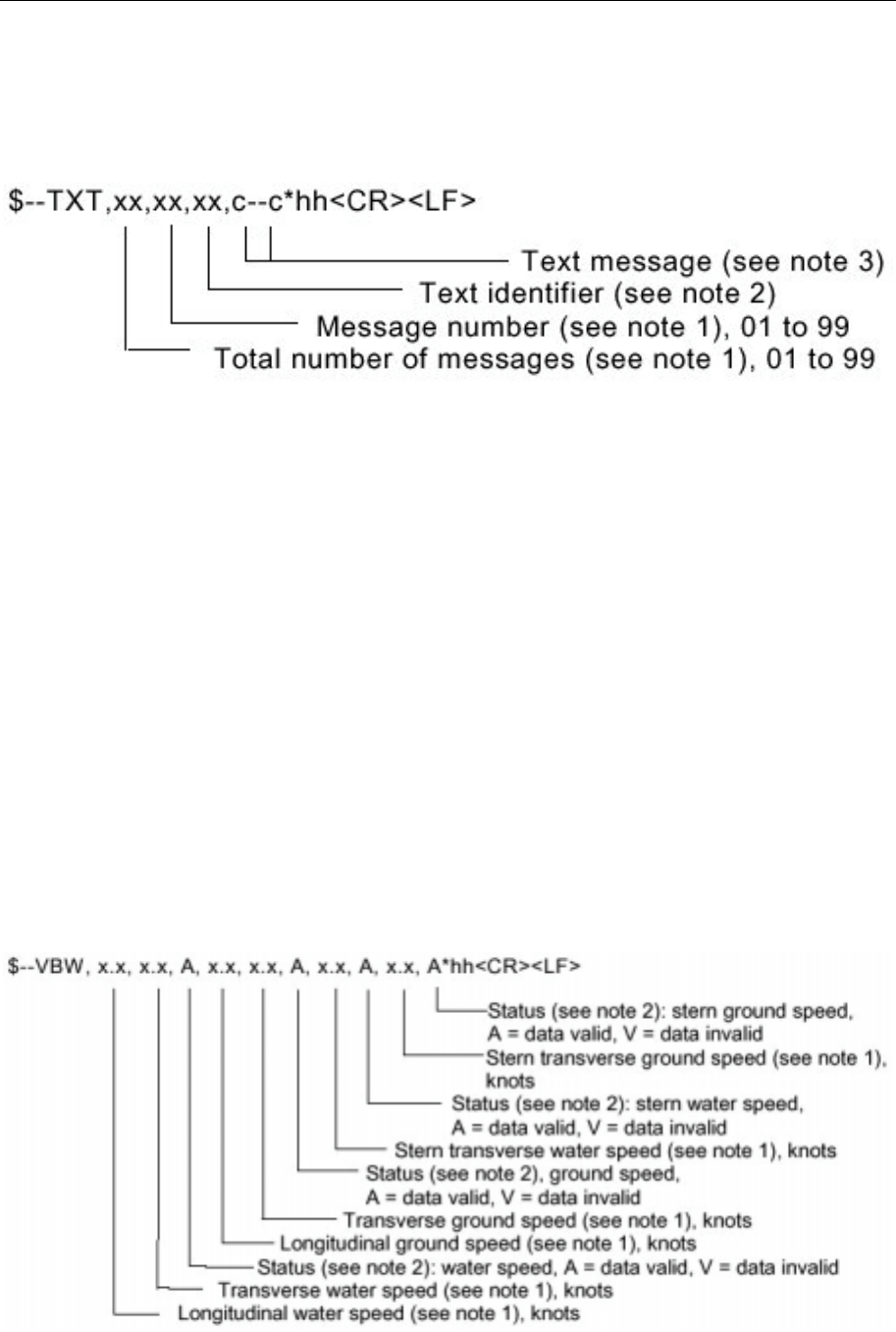
Seatex AIS 100 Instruction Manual, rev. 5 External interfaces
79
TXT – Text transmission
For the transmission of short text messages. Longer text messages
may be transmitted by using multiple sentences.
NOTE 1 Text messages may consist of the transmission of multiple messages
all containing identical field formats. The first field specifies the total
number of messages, minimum value = 1. The second field identifies
the order of this message (message number), minimum value = 1. For
efficiency, it is recommended that null fields be used in the additional
sentences, otherwise data is unchanged from the first sentence.
NOTE 2 The text identifier is a number, 01 to 99, used to identify different text
messages.
NOTE 3 ASCII characters, and code delimiters if needed, up to the maximum
permitted sentence length (i.e. up to 61 characters including any code
delimiters).
All fields are used by the AIS.
VBW – Dual ground/water speed
Water-referenced and ground-referenced speed data.
NOTE 1 Transverse speed: "-" = port, Longitudinal speed: "-" = astern.
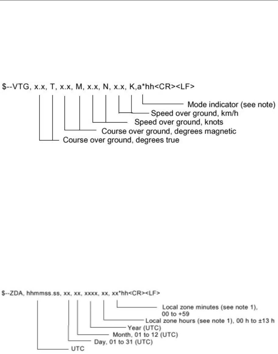
Seatex AIS 100 Instruction Manual, rev. 5 External interfaces
80
NOTE 2 The status field shall not be a null field.
All fields are used by the AIS except Stern speed.
VTG – Course over ground and ground speed
The actual course and speed relative to the ground.
NOTE Positioning system Mode indicator:
A = Autonomous mode
D = Differential mode
E = Estimated (dead reckoning) mode
M = Manual input mode
S = Simulator mode
N = Data not valid
The positioning system Mode indicator field shall not be a null field.
Course over ground, degrees magnetic and Speed over ground km/h
are not used by the 'AIS
ZDA – Time and date
UTC, day, month, year and local time zone.
NOTE 1 Local time zone is the magnitude of hours plus the magnitude of
minutes added, with the sign of local zone hours, to local time to
obtain UTC. Local zone is generally negative for East longitudes with
local exceptions near the International Date Line.
Example: At Chatham Is. (New Zealand) at 1230 (noon) local time on June 10,
1995:
$GPZDA,234500,09,06,1995,-12,45*6C<CR><LF>

Seatex AIS 100 Instruction Manual, rev. 5 External interfaces
81
In the Cook Islands at 1500 local time on June 10, 1995:
$GPZDA,013000,11,06,1995,10,30*4A<CR><LF>
All fields except Local zone, are used by the AIS.
6.7 Proprietary 61162-1 sentences
General
In order to configure and service the AIS mobile station there are
some proprietary messages that can be used. The AIS mobile station
uses the NMEA registered "STX" manufacturer’s code. When setting
parameters in the AIS mobile station use the $PSTXS command. To
query the AIS mobile station for information, use the $PSTXQ
command. Responses from the AIS mobile station uses the $PSTXR
command. The proprietary messages comply with IEC 61162-1 and
have the following structure:
$P STX S, <Msg ID> DATA * <FCS> <CR> <LF>
Field Definition
$ or ! Hex 24 or Hex 21 - Start of sentence
P Hex 50 – Proprietary sentence ID
STX Kongsberg Seatex mnemonic code
S or R or Q S = Set, R = Response, Q = Query
<Msg ID> Message ID identifying a specific sentence
DATA Data portion, unique for each Message ID.
* Checksum delimiter
<FCS> Checksum
<CR><LF> End of message
MSI number
To request the current MMSI number from the AIS mobile station, use
the command:
$PSTXQ,MMSI*<FCS><CR><LF>
The AIS mobile station response message has the format:
$PSTXR,MMSI,<nnnn>*<FCS><CR><LF>
To set or change the MMSI number, use the command:
$PSTXS,MMSI,<nnnn>*<FCS><CR><LF>
Seatex AIS 100 Instruction Manual, rev. 5 External interfaces
82
Field Description Range
MMSI Message ID identifying this sentence NA
<nnnn> MMSI number 0 to 1073741823
All fields are required and used.
IMO number
To request the current IMO number from the AIS mobile station, use
the command:
$PSTXQ,IMO*<FCS><CR><LF>
The AIS mobile station response message has the format:
$PSTXR,IMO,<nnnn>*<FCS><CR><LF>
To set or change the IMO number, use the command:
$PSTXS,IMO,<nnnn>*<FCS><CR><LF>
Field Description Range
IMO Message ID identifying this sentence NA
<nnnn> IMO number 0 to 1073741823
All fields are required and used.
Serial port communication parameters
To request the current communication parameters of the serial ports,
and to retrieve all available serial ports, use the command:
$PSTXQ,PORT*<FCS><CR><LF>
The AIS mobile station response message has the format (one
message per port):
$PSTXR,PORT,CCCC,<bbbb>,<p>,<d>,<s>*<FCS><CR><LF>
To set or change the communication parameters, use the command:
$PSTXS,PORT,CCCC,<bbbb>,<p>,<d>,<s>*<FCS><CR><LF>

Seatex AIS 100 Instruction Manual, rev. 5 External interfaces
83
Field Description Range
PORT Message ID identifying this
sentence NA
CCCC Name of serial port COM1 to COM32
<bbbb> Baud rate 1200 to 38400
<p> Parity, 'N' = None, 'E' = Even,
'O' = Odd 'N', 'E', 'O'
<d> Data bits 5-8
<s> Stop bits 1, 2
All fields are required and used.

Seatex AIS 100 Instruction Manual, rev. 5 External interfaces
84
Blank page

Seatex AIS 100 Instruction Manual, rev. 5 Software setup procedure
85
7 SOFTWARE SETUP PROCEDURE
7.1 Description of installation setup
The AIS 100 mobile station is set up with factory settings during
testing. The installation setup must be performed as a part of the AIS
100 system installation.
The installation setup is found in the highlighted sub-menus (4, 7, 9 &
c) in the Main Menu.
=== Main Menu ======== P1
1. Nav.Status
2. Long Range history
3. Voyage Data
4. Static Data
5. Dynamic Data
6. Chn.Management
7. VHF Link
8. Downperiods
9. Network & Ports
a. Answer Mode
b. Diagnostics
c. Security
x.yy.zz
This is the Main Menu page for the Seatex AIS
100 with sub-menus. Press the MENU button on
the MKD unit to access the sub-menus.
In order to make changes to any data field, use the
WHEEL to select desired line and confirm with
the ENTER button. Edit the data field by selecting
the symbol (arrow with bar) and (enter) in the end
of the bottom line. Type new data entry and
confirm with ENTER.
=== Security ======== P1C
Authorisation
L1 PIN Code :*******
L2 PIN Code :*******
Nav.Status :1
Route Plan :2
Voyage Data :0
Static Data :0
Chn.Mgmt :1
VHF Link :1
Serial Ports :0
Netw.Settings :1
Answer Mode :0
Security
A default authorisation code is used for altering
the data fields in the authorisation page. The
level 1 and 2 PIN codes control access to the listed
sub-groups. The lower level (0) gives limited
access and needs no access code. The higher level
(2) gives unrestricted access to all of the AIS 100
mobile station parameters.
All entries on this page are protected by level 2
PIN code.
Setup procedure:
Enter new PIN codes and choose suitable access
levels for the group data.
The Default PIN code 1 & 2 and a Master
Password can be handled out from Kongsberg
Seatex Custom Support.
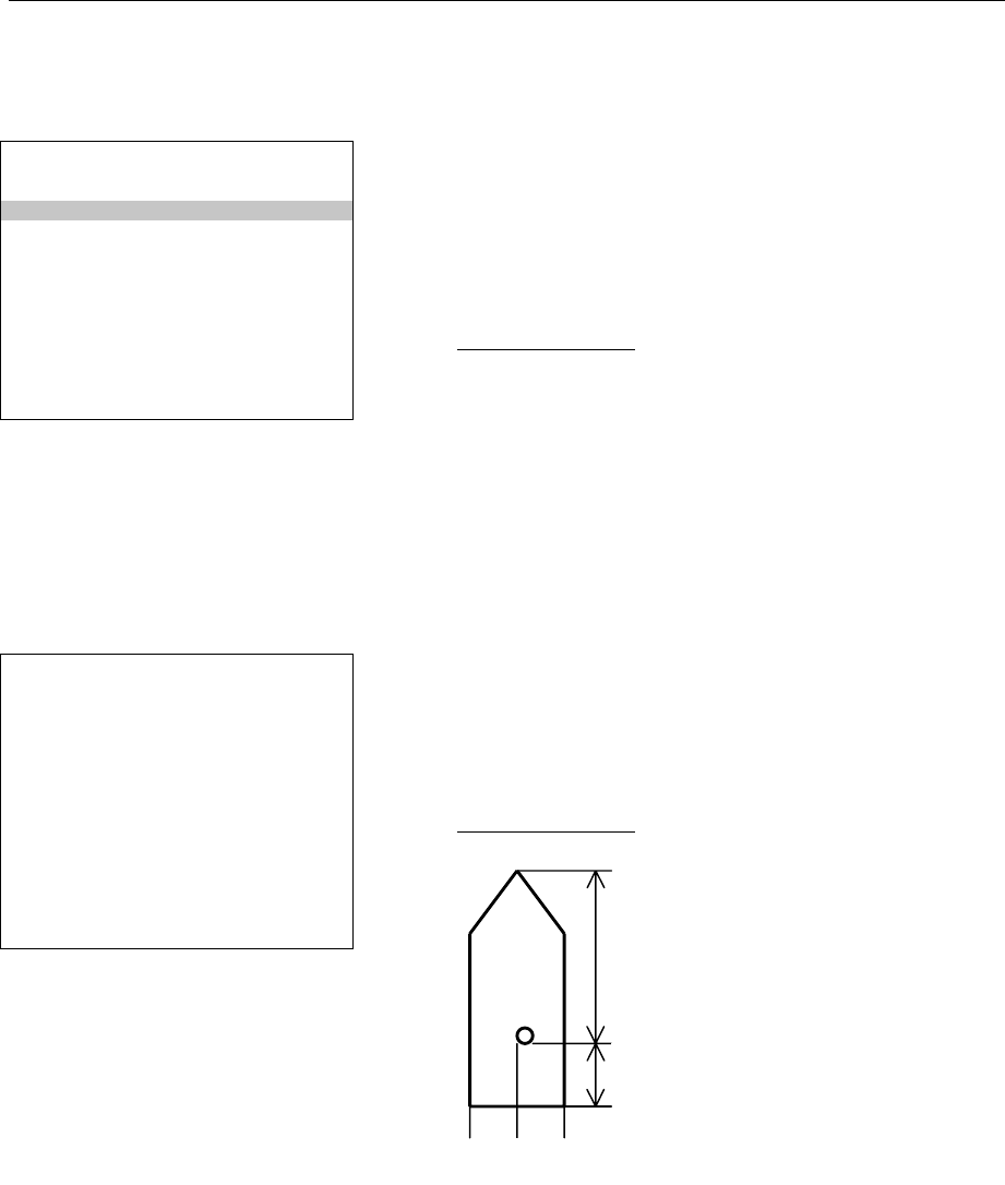
Seatex AIS 100 Instruction Manual, rev. 5 Software setup procedure
86
Static Data is divided into three groups.
=== Static Data ===== P14
Own Ship 1/3
Name :ANNE BERIT
Call :TA164GH
Mmsi :14395769235
Imo :10978974453
Type :51
Keel :12
Static Data Own Ship is used for entering the
vessel's own static data, i.e. ship data that does not
change from one voyage to another
The parameters necessary to customise are:
Setup procedure:
Name: The vessel name.
Call: The vessel call sign.
MMSI: The Maritime Mobile Signal Identifier
number.
IMO: The vessel IMO number.
Type: Type of vessel.
Keel: Height over keel. Total height of vessel in
metres.
=== Static Data ===== P14
AIS Transceiver 2/3
Length A:30
Length B:10
Length C:7
Length D:7
========================
1234567890*< >
Static Data Internal GPS antenna. It is
necessary to specify the exact position of the AIS
100's internal GPS antenna. No vertical
measurements are used.
Setup procedure:
Enter: A, B, C & D.
A
B
C
D
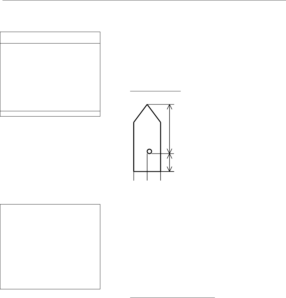
Seatex AIS 100 Instruction Manual, rev. 5 Software setup procedure
87
=== Static Data ===== P14
AIS Transceiver 2/3
Length A:30
Length B:10
Length C:7
Length D:7
========================
1234567890*< >
Static Data External GPS/GNSS Antenna. If the
vessel's own GPS/GNSS antenna is used as input
to the AIS 100 mobile station, the same
parameters are necessary. No vertical
measurements are used.
Setup procedure:
Enter: A, B, C & D.
=== VHF Link ======== P17
Ais Transceiver
ChnA :2087
ChnB :2088
TxPower :HIGH
BW A :Default
BW B :Default
Transmitter :TxON
VHF link. The AIS 100 Mobile station
transmitting power is normally set to High. The
channel management is normally atomised via
base stations, so the channel selection ChnA,
ChnB and the bandwidth BW A and BW B, shall
not be altered.
The VHF link page describes the current VHF
settings.
Setup procedure, check that:
ChnA=2087, ChnB=2088
BW A=Default, BW B=Default
TxPower is set to High.
High=12W, Low=2W
Transmitter=TxON
A
B
C
D

Seatex AIS 100 Instruction Manual, rev. 5 Software setup procedure
88
=== Serial Ports === P191
External ports
PILOT :38400
PI :38400
LongRange :4800
RTCM :4800
SENSOR-1 :4800
SENSOR-2 :4800
SENSOR-3 :4800
Network & Ports. The serial port baud rate must
be set up according to external instrumentation.
The Serial Ports page displays the baud rate for
all serial ports. The sensor interfaces comply with
the NMEA 183.
Setup procedure:
Change the baud rates accordingly.
=== Netw.Settings == P192
External ports
IP-adr :10.0.21.53
SubNet :256.256.256.256
Gateway :10.0.21.1
MAC MS :000.005.190
MAC LS :000.000.244
Local Area Network. A network administrator
will provide the appropriate settings.
The Network page displays the network settings.
Setup procedure:
Change the network setting accordingly.
MAC xx: the processing cards MAC address.
Note!
If a local PC is used outside a network server, use
a crossed UTP cable to connect LAN. Set up the
PC accordingly.

Seatex AIS 100 Instruction Manual, rev. 5 Maintenance
89
8 MAINTENANCE
8.1 General
The Seatex AIS 100 consists of both software and hardware. The
software part can be reinstalled or upgraded to the latest version in the
field by running a software installation procedure. Service of the
Seatex AIS 100 hardware in the field can consist of:
• Exchange of damaged GPS or VHF antenna cables.
• Exchange of failed GPS or VHF antennas.
• Exchange of failed Seatex AIS 100 mobile station .
The Seatex AIS 100 requires a skilled technician to maintain most of
the hardware service.
8.2 Periodic maintenance
The AIS 100 should regularly be checked for firm and fixed mounting
of the chassis in order to avoid vibration and shock. All connectors
should be checked for good mechanical and electrical connections.
Cables should not be bent more than the minimum recommended
bending radius and there should be no sharp bends on coaxial cables.
All cables should be fixed tight and rigid to their supporting structure
(bulkhead, mast etc.) and special care should be taken where cables
run through holes with sharp edges.
A properly operating unit will show when it is transmitting and
receiving messages by short blinks on the TX and MSG LEDs.
Inspecting the LEDs for normal operation gives a good indication of
the operating status. In particular, there should be no red LEDs,
because red indicates alarms or severe faults. Any red LED indication
means that further investigation and servicing is necessary.
8.3 Repairs and modifications
Repair of the Seatex AIS 100 consists of exchange of damaged
antenna cables, exchange of GPS or VHF antenna and replacement of
the Seatex AIS 100 mobile station, connection box or MKD. Any
skilled electrician should be able to do this.

Seatex AIS 100 Instruction Manual, rev. 5 Maintenance
90
8.3.1 Exchange of antenna cable
1. Disconnect the power cable from the Seatex AIS 100.
2. Dismount the damaged antenna cable. The new antenna cable
must be as straight as possible. Do not crush or crimp the cable,
as this will affect the electrical properties of the cable.
3. Connect the antenna cable to the antenna.
4. The connection between the antenna and the antenna cable should
be sealed against water penetration, preferably by using
waterproof self-vulcanising tape or shrink stocking with glue.
5. Connect the antenna cable to the Seatex AIS 100 unit and reapply
power by connecting the power cable.
Caution! If the antenna cable is attached to the unit, do not attach the
antenna cable to the antenna with the Seatex AIS 100 powered on.
If the antenna cable is short-circuited with power on, the GPS
receiver within the unit can be damaged.
8.3.2 Exchange of GPS or VHF antennas
1. Disconnect the power cable from the Seatex AIS 100 .
2. Dismount the failed antenna.
3. Mount the new antenna on the antenna rod.
4. Connect the antenna cable to the antenna.
5. The connection between the antenna and the cable should be
sealed against water penetration, preferably by using waterproof
self-vulcanising tape.
6. Connect the antenna cable to the Seatex AIS 100 .
Caution! If the antenna cable is attached to the unit, do not attach the
antenna cable to the new antenna with the AIS 100 unit powered on.
If the antenna cable is short-circuited with power on, the GPS
receiver within the unit can be damaged.
8.3.3 Repair of the Seatex AIS 100
The Seatex AIS 100 is not designed for customer repair. All repairs
and modifications of the unit, except installation of new software
versions and setup of the system, should be carried out by Seatex
qualified personnel. A failed unit should be shipped back to Seatex for
repair.

Seatex AIS 100 Instruction Manual, rev. 5 Maintenance
91
8.4 Installation of a spare Seatex AIS 100
1. Disconnect the power cable from the AIS 100.
2. Disconnect the unit to be repaired from its cables and the rack, and
replace it with the spare unit.
3. Connect all cables as they were on the original unit.
4. Connect the power cable.
5. Configure the new unit as described in chapter 7.

Seatex AIS 100 Instruction Manual, rev. 5 Maintenance
92
Blank page

Seatex AIS 100 Instruction Manual, rev. 5 Troubleshooting
93
9 TROUBLESHOOTING
If the initialisation process fails, the alarm LED will turn red. Mobile
station failure can be divided into two categories:
• Hardware problems
• External interface problems
9.1 Hardware problems
Hardware problems can be divided into the following categories:
• Power supply failing
• GPS receiver failing
• VHF transceiver failing
• GPS and VHF antennas and cables
• Interface cables
9.1.1 Power supply failing
If the lamp PWR on the front of the mobile station does not light
green, the unit does not receive power. First check the fuse in the
connection box. If the fuse is OK, check that external power has been
connected to terminal screws 37 to 40 in the AIS 100 connection box
as stated in section 5.4 and that the supplied power is in accordance
with technical power specifications, section 4.3. If the transponder
outputs an alarm, the alarm condition can be read from the display.
9.1.2 GPS and VHF antenna cable connections
Typical problems when no GPS signal is received is that the GPS
antenna cable and/or connectors are damaged as well as loose or that
the cables are not properly connected. In order to check for antenna
cable problems, ensure that the GPS antenna is disconnected. The
Ohm reading between the centre and the shelf should be infinite if
there is no short-circuit in the cable. Make a short-circuit in the
opposite end of the cable and measure the resistance. Now the reading
should be approximately 0 Ohm.
9.1.3 GPS and VHF antenna malfunction
Disconnect the GPS antenna cable at the rear side of the mobile
station. Measure the resistance between the centre pin and shield in
the cable (with the antenna connected). The GPS antenna does not
have a defined resistance that can be measured. Therefore, before
measurements can be carried out, the antenna end of the cable needs

Seatex AIS 100 Instruction Manual, rev. 5 Troubleshooting
94
to be short-circuited. Measure between centre conductor and shield.
Resistance should be close to 0 Ohm.
Note! Switch off the power before disconnecting the antenna.
9.1.4 GPS receiver failing
If the mobile station does not compute position data and the GPS lamp
on the front of the mobile station does not light green, the GPS PPS
pulse is not being received and the GPS receiver inside the mobile
station should be checked. Disconnect the antenna cable at the rear
side of the hardware unit. The voltage output on the GPS antenna
connector should be approximately 4.8 – 5.0 V and indicates that the
GPS receiver supplies voltage to the antenna. If not, this indicates
problems with the GPS receiver. Disconnect and connect power (a
few times) and see if the mobile station starts up as normal. If not,
consult Seatex for advice.
9.1.5 VHF transceiver failing
If the VHF antenna and antenna cabling is OK and the MSG lamp on
the front of the mobile station does not light green and amber vice
versa, this indicates incorrect data reception on AIS channel 1 and 2.
Disconnect and connect power (a few times) and see if the mobile
station starts up as expected. If not, consult Seatex for advice.
9.2 External data interface problems
External data connections may be incorrect:
• Data input from main GPS source
• Heading from vessel heading sensor
9.2.1 Data input from main GPS/GNSS source
Position data output from the AIS mobile station is generated from the
vessel main GPS/GNSS receiver and received into the AIS unit using
serial line communication. If data is missing into the AIS mobile
station, the following steps should be taken in order to check for
missing position data:
• Check that cable connections are correctly terminated in the
connection box (terminal screws 19 to 27).
• If properly connected, check the serial line communication (baud
rate, parity, number of bytes transmitted, number of stop bits)

Seatex AIS 100 Instruction Manual, rev. 5 Troubleshooting
95
between transmitting (vessel GPS/GNSS receiver) and receiving
(parameters to be checked from the MKD unit) end.
• If OK, check that the position output format from the GPS/GNSS
receiver is in accordance with the expected input position format.
• If the mobile station still does not receive position data, consult
Seatex for advice.
9.2.2 Heading from vessel heading sensor
Heading data is received from the vessel gyro or magnetic compass. If
input data is missing, the following steps should be taken in order to
check for missing heading data:
• Check that cable connections are correctly terminated in the
connection box (terminal screws 19 to 27).
• If correctly connected, check the serial line communication (baud
rate, parity, number of bytes transmitted, number of stop bits)
between transmitting (vessel heading sensor) and receiving
(parameters to be checked from the MKD unit) end.
• If OK, check that the heading output format from the compass is
in accordance with the expected input heading format.
• If the mobile station still does not receive heading data, consult
Seatex for advice.
If the mobile station fails to operate properly, remove power by
removing the + 24 V power supply cable and then reapply power. The
mobile station should now initialise from start.

Seatex AIS 100 Instruction Manual, rev. 5 Troubleshooting
96
Blank page

Seatex AIS 100 Instruction Manual, rev. 5 Parts list
97
10 PARTS LIST
The standard Seatex AIS 100 consists of:
Part No No Description
A120-01 This package consists of a complete Seatex AIS
100, with all necessary parts except for antenna
brackets and power cable. GPS and VHF
antenna cables have to be ordered separately.
The transponder is supplied for table mounting.
The MKD is delivered for console mounting.
The package consists of the following items:
A100-50 Seatex AIS 100 mobile station
A100-51 Seatex AIS 100 MKD (Minimum Keyboard
Display)
A100-54 Seatex AIS 100 connection box including 3 m
interface cable
A100-56 GPS antenna
A100-61 Connector kit for GPS antenna cable (RG214),
two connectors
A100-81 Adapter cable set for GPS antenna cable, two
cables length 0,5 m
A100-57 VHF antenna
A100-66 Connector kit for VHF antenna cable (RG214),
two connectors
A100-65 GPS antenna mounting rod, 0,5 m
A100-76 Interface cable to MKD 100, length 7 m,
connectors mounted
A100-82 Manual set for Seatex AIS 100

Seatex AIS 100 Instruction Manual, rev. 5 Parts list
98
Blank page

Seatex AIS 100 Instruction Manual, rev. 5 Appendix A – Vessel types
99
Appendix A – Vessel types
Identifiers to be used by ships to report their type
Identifier No. Special craft
50 Pilot vessel
51 Search and rescue vessels
52 Tugs
53 Port tenders
54 Vessels with anti-pollution facilities or equipment
55 Law enforcement vessels
56 Spare – for assignments to local vessels
57 Spare – for assignments to local vessels
58 Medical transports (as defined in the 1949 Genova Conventions and
Additional Protocols)
59 Shops according to RR Resolution No. 18 (Mob-83)
Other Ships
First digit1) Second digit1) First digit1) Second digit1)
1 – reserved for
future use 0– All ships of this type - 0 – Fishing
2 – WIG 1 – Carrying DG, HS or
MP, IMO hazard or
pollutant category A
- 1 – Towing
3 – see right
column 2 – Carrying DG, HS, or
MP, IMO hazard or
pollutant category B
3– Vessel 2 – Towing and length
of the tow exceeds
200 m or breadth
exceeds 25 m
4 – HSC 3 – Carrying DG, HS, or
MP, IMO hazard or
pollutant category C
- 3 – Engaged in
dredging or
underwater
operations
5 – See above 4 – Carrying DG, HS, or
MP, IMO hazard or
pollutant category D
- 4 – Engaged in diving
operations
5 – Reserved for future
use - 5 – Engaged in military
operations
1 The identifier should be constructed by selecting the appropriate first and second digits

Seatex AIS 100 Instruction Manual, rev. 5 Appendix A – Vessel types
100
Identifiers to be used by ships to report their type
Other ships
First digit Second digit First digit Second digit
6 – Passenger
ships 6 – Reserved for future
use - 6 – Sailing
7 – Cargo ships 7 – Reserved for future
use - 7 – Pleasure craft
8 – Tanker(s) 8 – Reserved for future
use - 8 – Reserved for future
use
9 - Other types of
ship 9 – No additional
information - 9 – Reserved for future
use
DG: dangerous goods
HS: harmful substances
MP: marine pollutants
Seatex AIS 100 Instruction Manual, rev. 5 Appendix B – Declaration of conformity
101
Appendix B – Declaration of Conformity

Seatex AIS 100 Instruction Manual, rev. 5 Appendix B – Declaration of conformity
102
Blank page

Seatex AIS 100 Instruction Manual, rev. 5 Index
103
Index
A
ABK · 2
ABM · 2
ACA · 2
Add Regions · 18
AIS · 1, 2
AIS frequencies · 7, 17
AIS message type · 9
AIS mobile station · 3, 5, 6, 8, 13, 15, 33, 34, 45, 81, 82,
94
AIS transceiver entry · 15
Alarm · 26
ALM LED · 46
ALR · 2
Answer mode · 19
antenna cable length · 44, 45
antenna cabling · 45, 94
assigned mode · 9
attenuation · 43, 44, 45
authorisation · 21, 85
autonomous · 9, 73, 74, 78, 80
B
BIIT · 2
brightness · 26
Broadcast messages · 23, 25
BS · 2
built-in alarm · 46
C
Channel Management · 17, 56, 57
Clear message · 25
climatic conditions · 27
COG · 2
connection box · 8, 10, 29, 33, 34, 35, 37, 38, 41, 89
connector data/power · 40
connectors · 37
contrast · 26
D
Data reporting · 5
data/power connector · 40
datum · 70
DGPS · 2
Diagnostics · 13, 20, 85
differential corrections · 7, 46, 75, 76
differential data · 76
Downperiods · 13, 18, 85
DSC · 2
Dynamic data · 16
E
ECDIS · 2
ECS · 2
Edit Current Region · 17
electromagnetic compatibility · 27
EMC · 2
EN60945 · 27
EN60950 · 27
ETA · 2, 5, 14, 61
F
factory settings · 85
FATDMA · 2
G
GLONASS · 72, 74, 75, 76
GNSS · 2
GPS · 2
GPS antenna · 8, 31, 33, 36, 37, 44, 45, 86, 93, 94
GPS antenna installation · 44
GPS antenna offset · 45
GPS/GNSS · 16, 34, 87, 94, 95
H
handled long range (lr) · 14
hardware · 89, 94
HDG · 2
heading data · 95
high speed serial data · 41
I
IALA · 2
IEC · 2
IMO · 2, 5, 14, 15, 34, 48, 61, 70, 76, 78, 82, 86, 99
IMO number · 5, 15, 48, 61, 82, 86
Inbox · 22, 23, 25
input sentences · 48, 49, 50
installation · 33
Installation
Set-up · 85
interface – Long Range · 49
interface – presentation · 47, 48
internal alarm · 46
internal interface · 36
ITU-R M.1371 · 51, 52, 53, 54, 55, 56, 58, 59, 64, 65, 66,
67, 68, 69, 70

Seatex AIS 100 Instruction Manual, rev. 5 Index
104
L
LAN · 2
LED · 2
LED indicators · 7
listener · 2, 8, 41
Local area network · 2, 19, 88
Long Range · 2, 11, 13, 19, 26, 49, 61, 85
long range (lr) · 13, 14
Long Range interface · 49
Long Range messages · 26
LR · 2
M
main GPS/GNSS receiver · 94
Main menu · 11, 13, 85
maintenance · 1, 89
malfunction · 10
message Clear · 25
message Long Range · 26
messages Broadcast · 23, 25
messages Predefined · 25
messages Safety related · 25
MKD · 2
MKD unit · 7, 11, 13, 27, 33, 34, 37, 85, 95
MMSI · 2, 5, 15, 22, 48, 51, 52, 54, 57, 60, 62, 63, 64, 81,
82, 86
mobile station · 7, 8, 31, 33, 35, 36, 37, 90, 93, 94
mobile station · 89
MSG · 2
MSI number · 81
N
N/A · 2
Nav Status · 13
network · 2, 8, 13, 19, 85, 88
Network · 2, 8, 13, 19, 85, 88
Network and ports · 19
NMEA · 2
NMEA 0183 · 6, 19
O
Outbox · 22, 23, 24, 25
P
PI · 2
pin layout data/power connector · 40
polled · 9, 10
polled mode · 10
Port configuration · 47, 49
PPS · 2
Predefined messages · 25
presentation interface · 47, 48
product safety · 27
PWR · 2
R
range · 4, 8, 13, 22, 28, 29, 42, 49, 54, 64, 69, 72
Rate of Turn · 2, 51
Real Time Kinematic · 73, 75
ROT · 2
RS · 3
RTCM · 2
S
Safety related messages · 25
screw terminals · 38
Security · 21
serial interface · 20
Serial ports · 19
setup · 21, 85, 90
shielded twisted pair · 41
SMS · 22
SOG · 3
SOTDMA · 3, 4
Static Data · 5, 13, 15, 16, 21, 65, 68, 85, 86, 87
static data field · 15
static data GPS · 16
Static Data Internal GPS antenna · 86
Static Data Own Ship · 86
SWR · 3
T
talker · 8, 41, 66
TBD · 3
TDMA · 3
third wire · 41
twisted pair - shielded · 41
TX · 3
TXT · 3
U
unpacking and handling · 33
UTC · 3
V
VDL · 3
VDM · 3
VDO · 3
VHF · 3
VHF antenna · 8, 30, 33, 36, 37, 42, 43, 44, 46, 89, 90,
93, 94
VHF communication · 3, 8
VHF coverage · 4
VHF link · 18, 87
VHF receiver · 7, 54
VHF signals · 42
vibration · 27, 89
View · 11, 22
View Regions · 17

Seatex AIS 100 Instruction Manual, rev. 5 Index
105
Voyage Data · 13, 14, 21, 85
VTS · 3
W
warranty · 27
Z
Zone · 17, 18