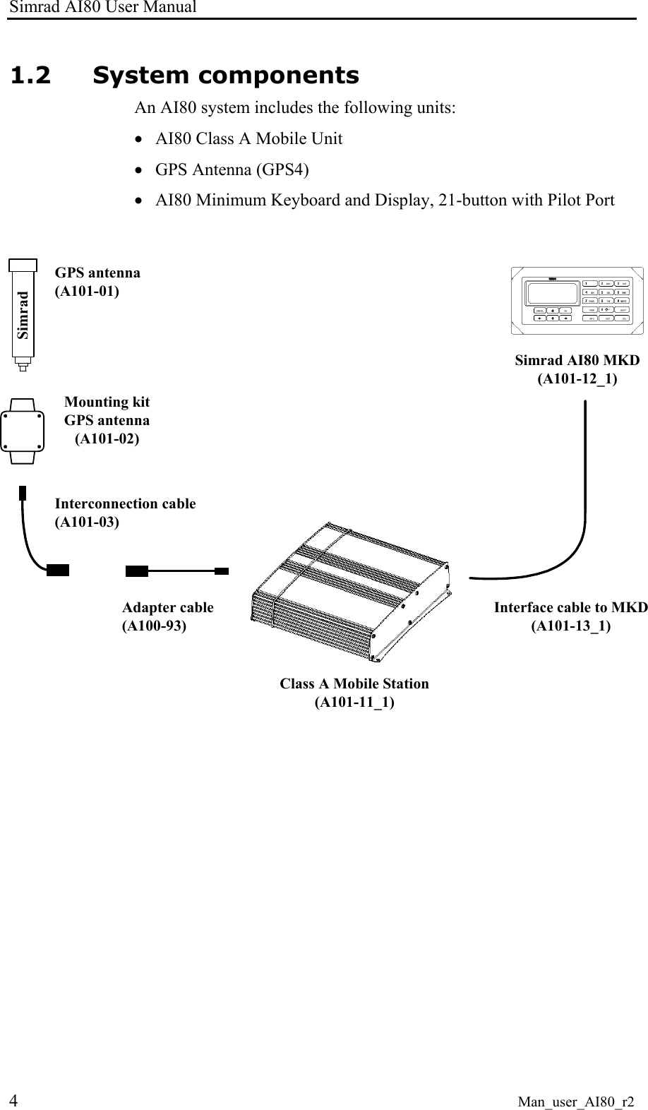
Kongsberg Seatex AS AIS200AI80 AIS200 Simrad AI80 User Manual Man user ai80 r2 not finished
Kongsberg Seatex AS AIS200 Simrad AI80 Man user ai80 r2 not finished
UserManual.wiki
>
Kongsberg Seatex AS
>
AIS200AI80 User Manual
>
Exhibit 8 User Manual
Contents
1.
Exhibit 8 User Manual
2.
Exhibit 8 Installation Guide
Exhibit 8 User Manual
Navigation menu
Upload a User Manual
Namespaces
Wiki Guide
HTML
PDF
Info
Views
User Manual
Discussion / Help
Navigation
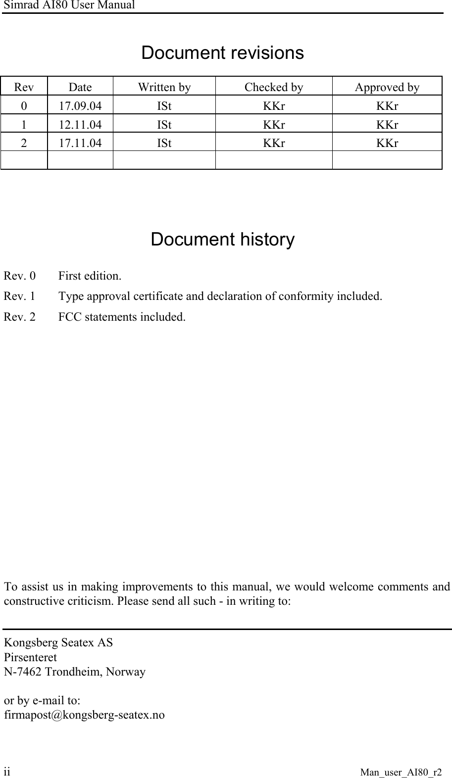
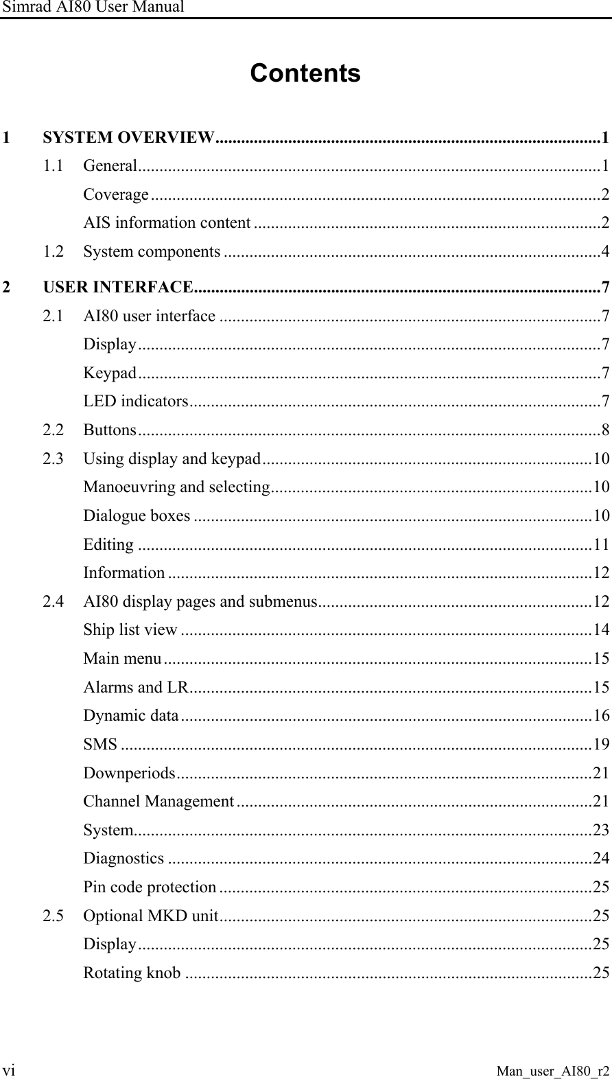
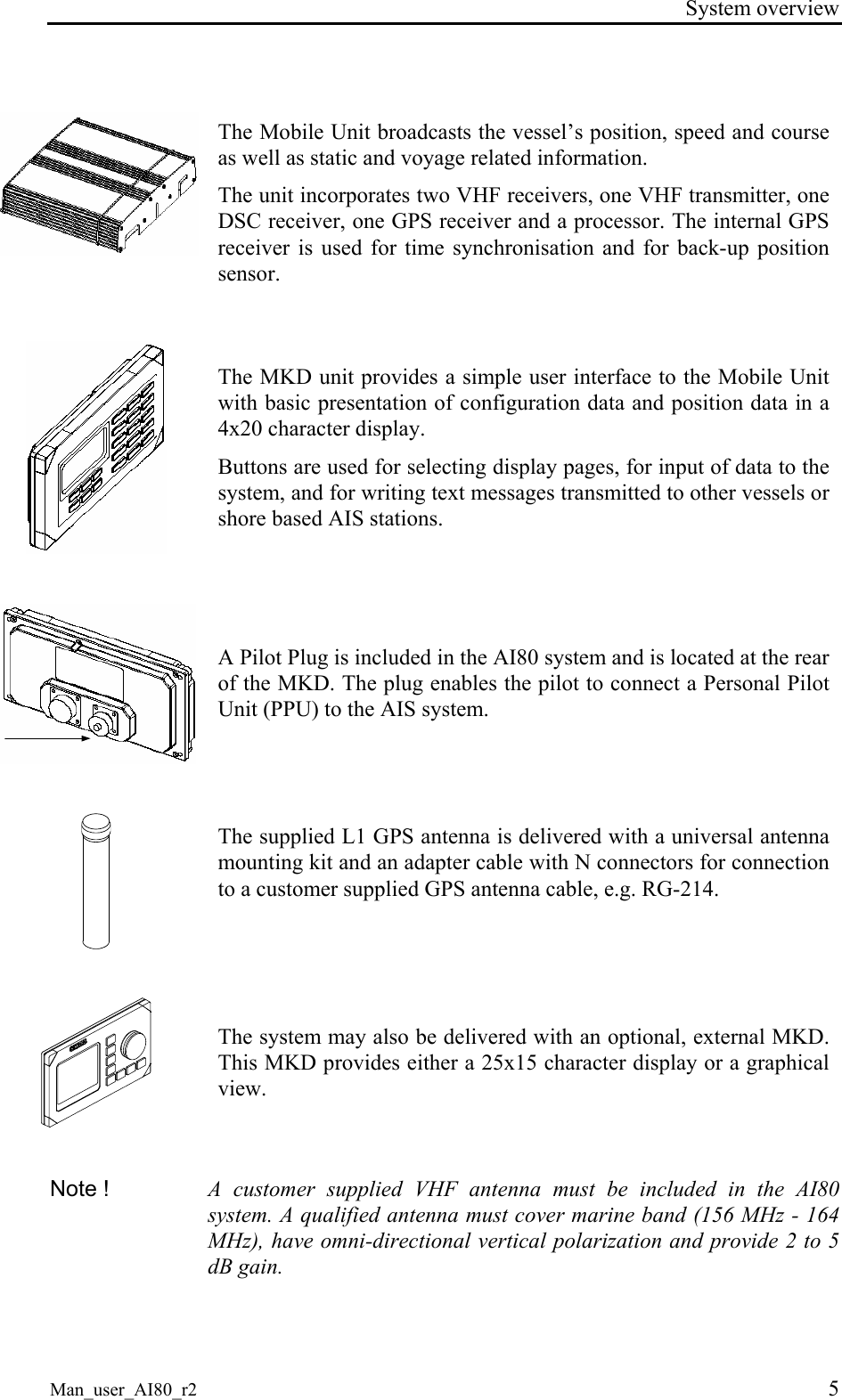
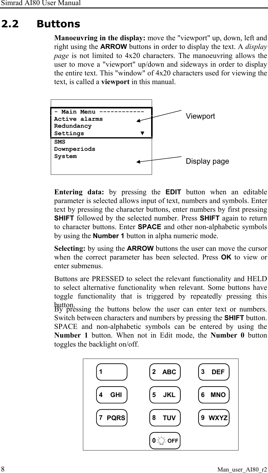
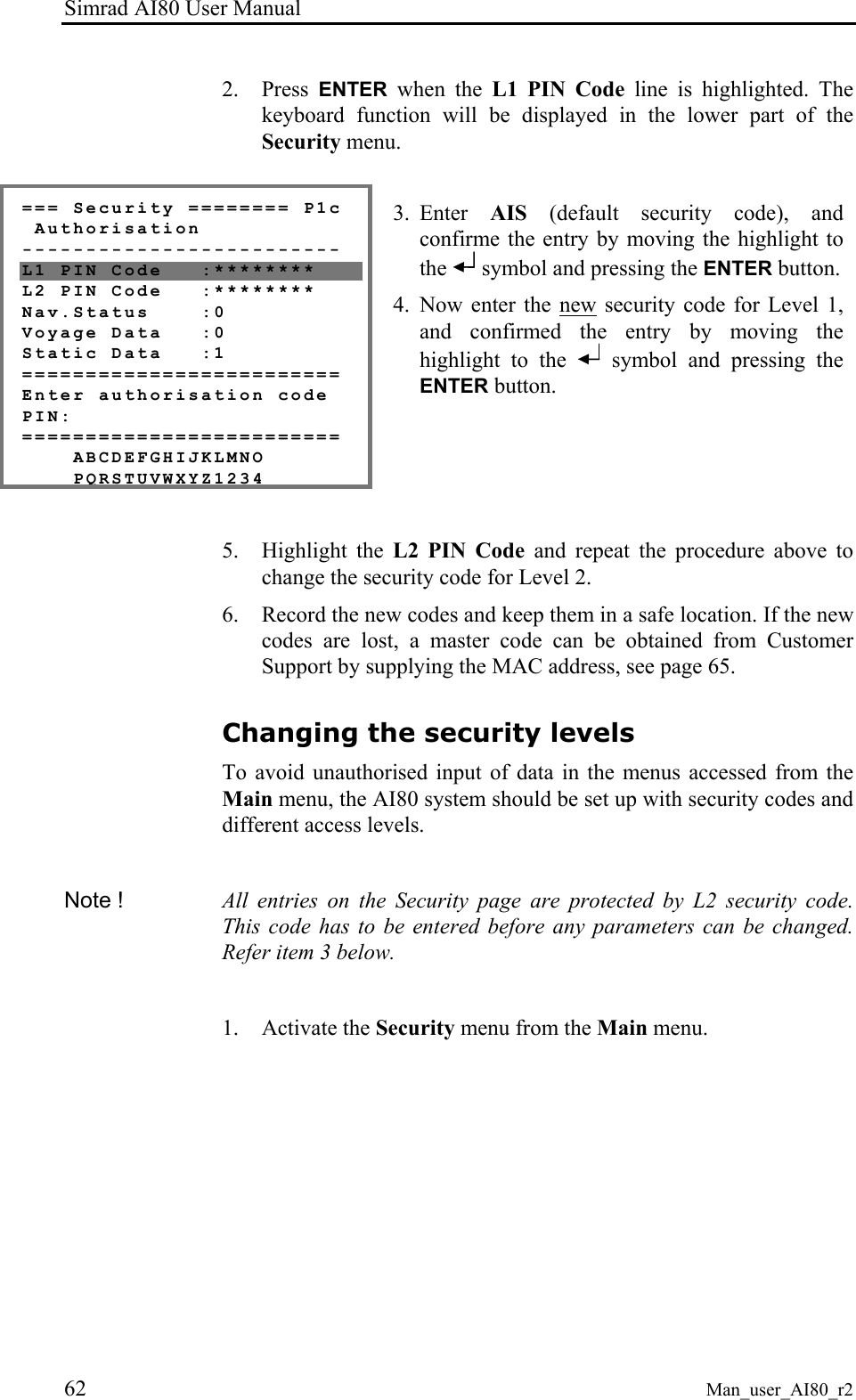
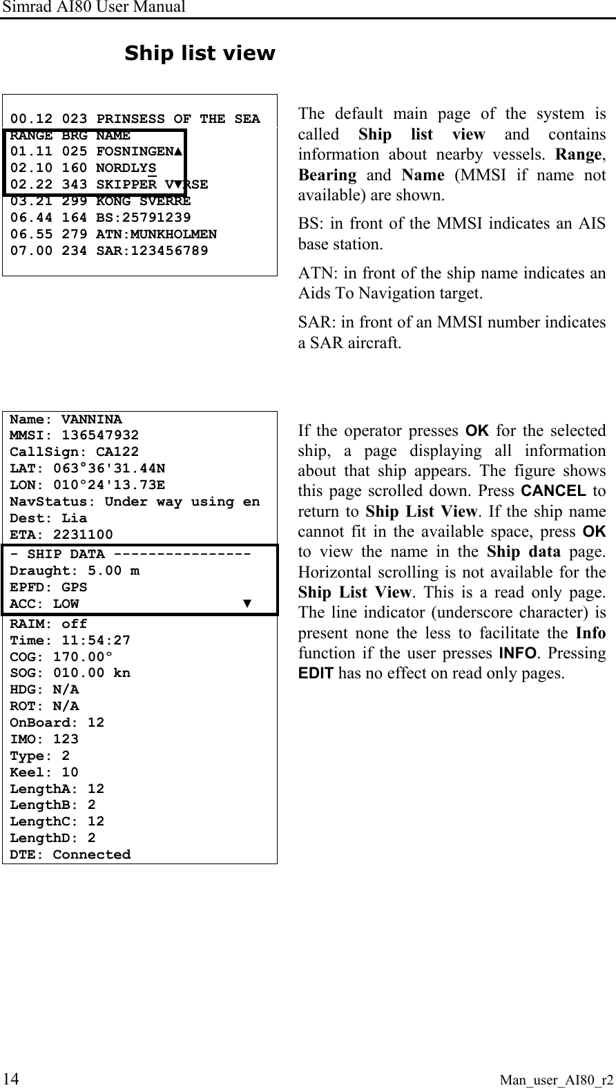
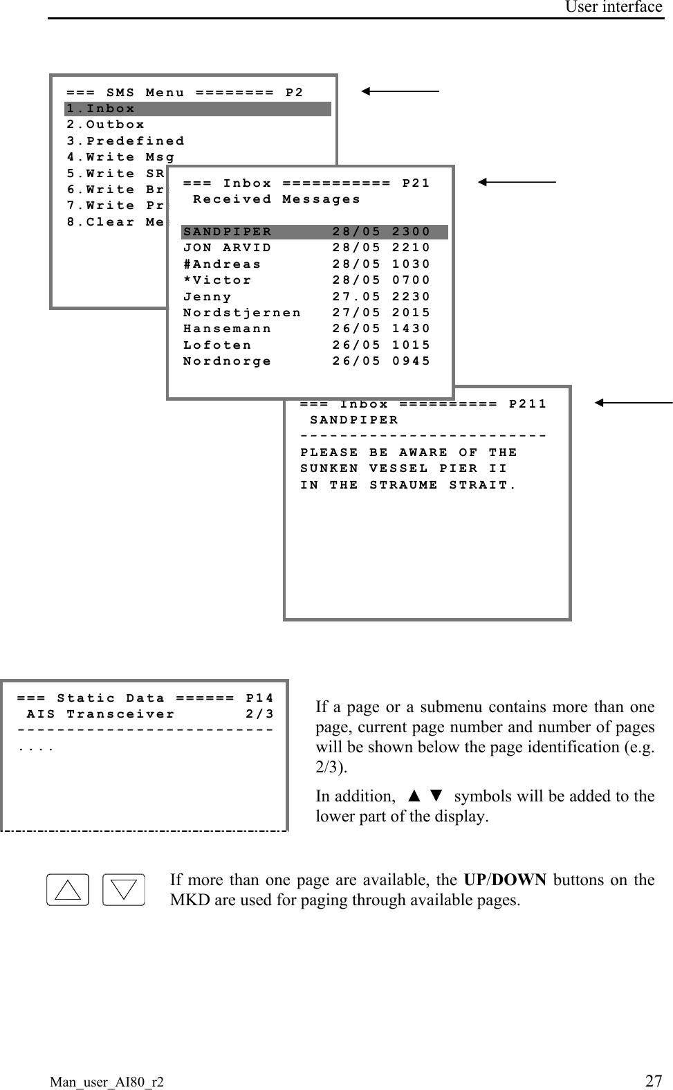
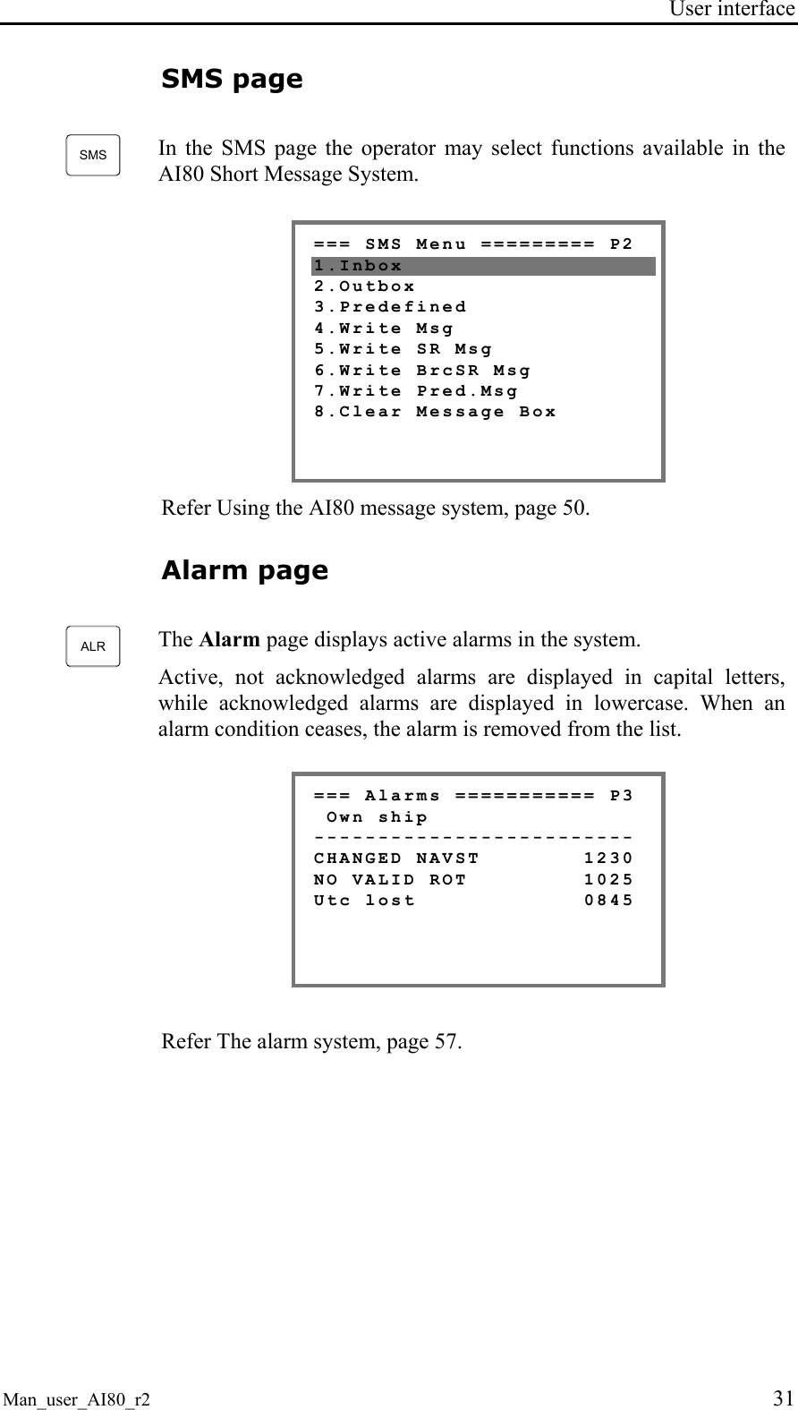
![User interface Man_user_AI80_r2 11 To facilitate recognition, the uppermost line on a dialogue box is composed of a start pattern of three * signs, and a post fixed pattern of * until the end of the line. A dialogue box prompting for PIN code appears like the figure below. *** PIN Code *********** *B [Cancel] [OK] Editing The user can edit a variable by pressing EDIT when highlighted. The value of the current variable is stored and the user can start editing the data. The user selects characters by repeatedly pressing numeric buttons, - Static data ---------- - Static data ---------- MMSI: 000000001 MMSI: 000000002 Pos Source: Internal Pos Source: Internal SurveyedLat: 00°00'▼ 1 x 2ABC SurveyedLat: 00°00'▼ or, in cases were there are predefined variables, chooses from a list of these by using the UP or DOWN ARROW buttons. - Serial -------------- - SETTINGS ------------- Sensor 1: 4800 Sensor 1: 4800 RTCM : 9600! RTCM : 4800! PI : 38400 ▼ 1 x 2ABC PI : 38400 ▼ The button between the displays indicates that pressing this button when in the screen to the left, will result in the changes seen in the screen to the right. After editing, press OK to confirm changes and exit Edit mode, or press CANCEL to discard changes. If the input exceeds the horizontal length of the display (20 chars), it automatically scrolls. When editing is completed and OK is pressed, it scrolls back. Values are saved by holding the OK button pressed.](https://usermanual.wiki/Kongsberg-Seatex-AS/AIS200AI80.Exhibit-8-User-Manual/User-Guide-492481-Page-21.png)
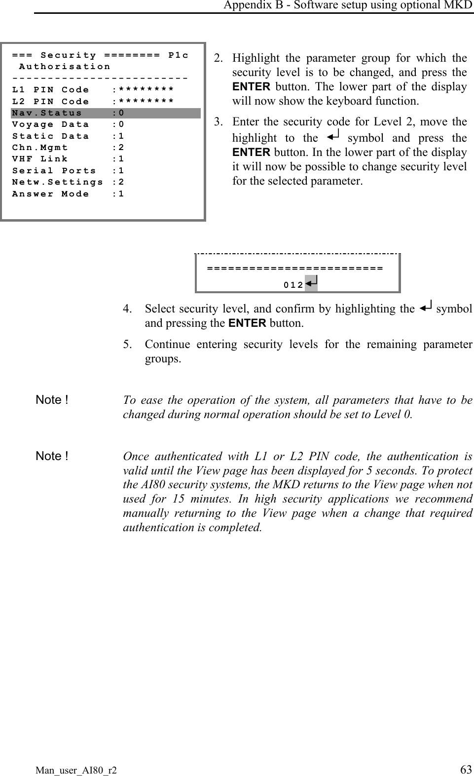
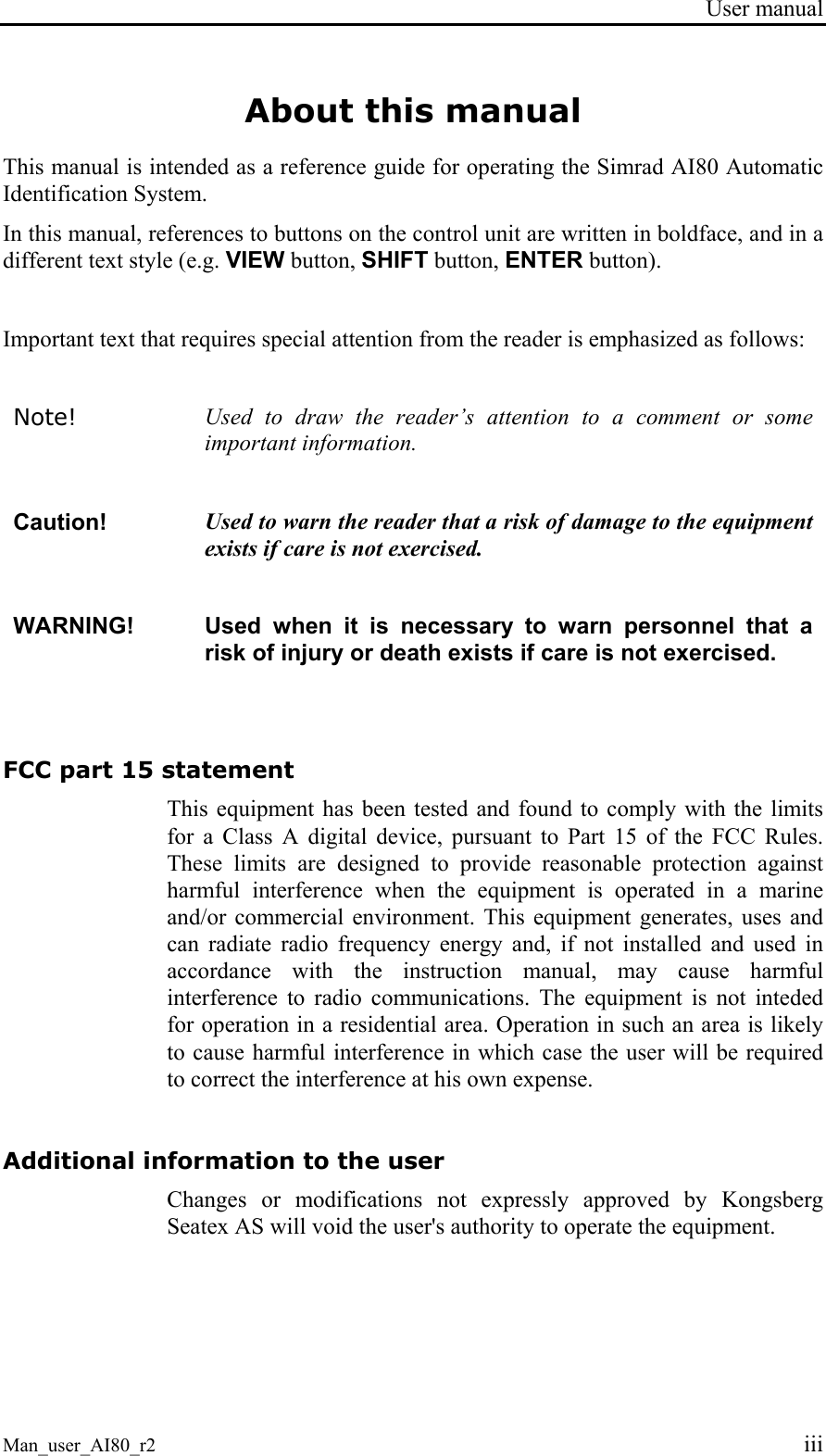
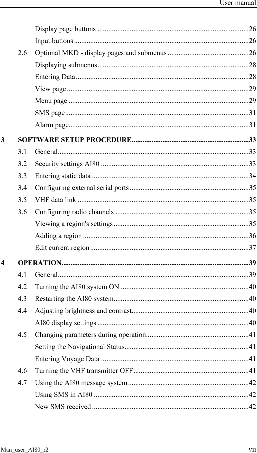
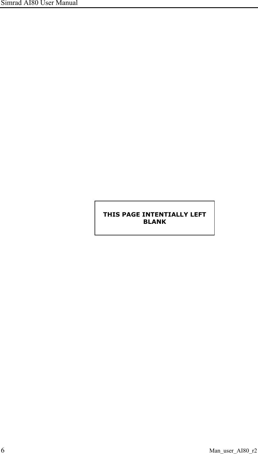
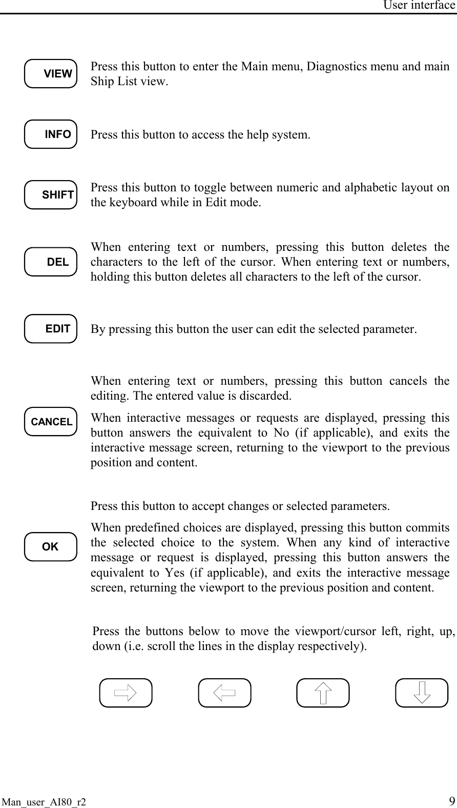
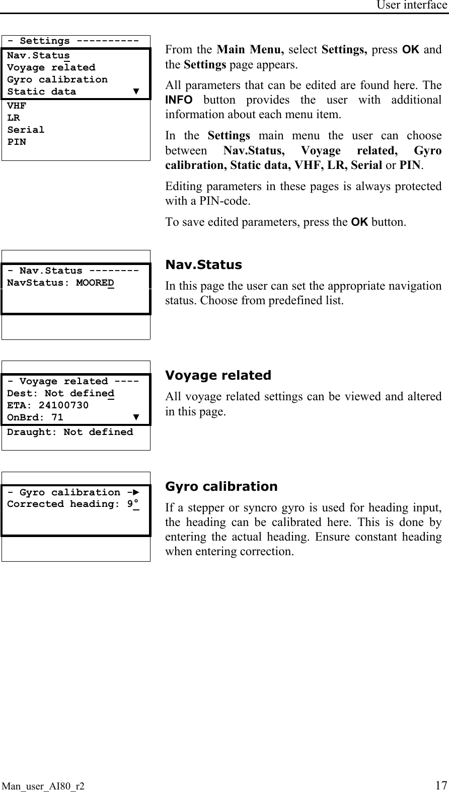
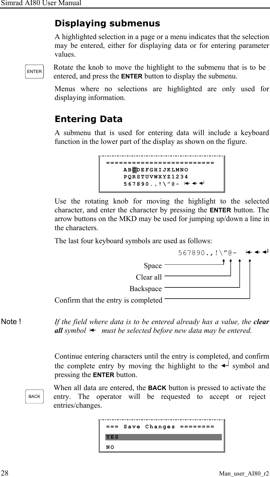
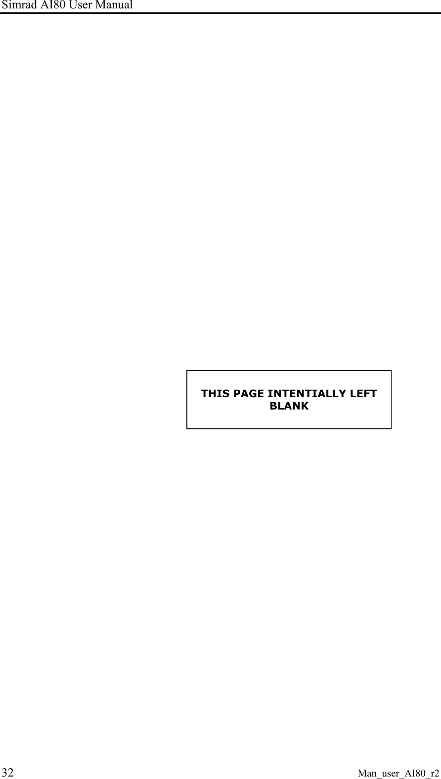
![Simrad AI80 User Manual 12 Man_user_AI80_r2 Information The Info functionality provides the user with information about the highlighted menu. A dialogue box with help text is provided if such a text is existent for the menu. If not, a default text is displayed. A user help dialogue box may look like this: *** User Help ****** Persons on board, Crew and passengers included [OK] 2.4 AI80 display pages and submenus The table below shows the menu hierarchy. The ARROW buttons, OK and CANCEL buttons are used to navigate in the menu tree. Navigation between Ship List, Main Menu and Diagnostics is done by pressing the VIEW button. This chapter describes all the menu pages in the system. Note ! If optional MKD is connected to the AI80, the menus for optional MKD will also apply to the AI80.](https://usermanual.wiki/Kongsberg-Seatex-AS/AIS200AI80.Exhibit-8-User-Manual/User-Guide-492481-Page-22.png)
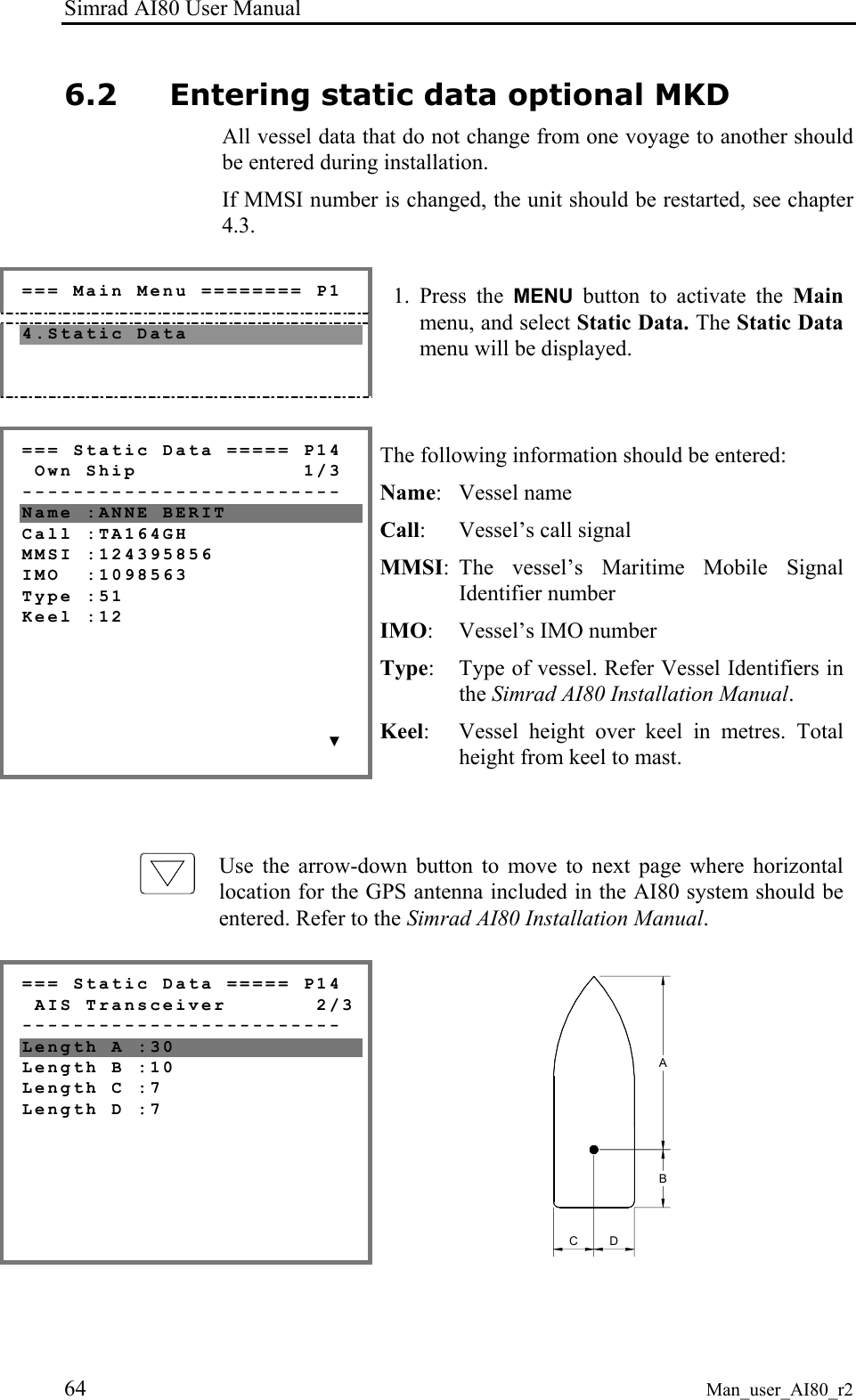
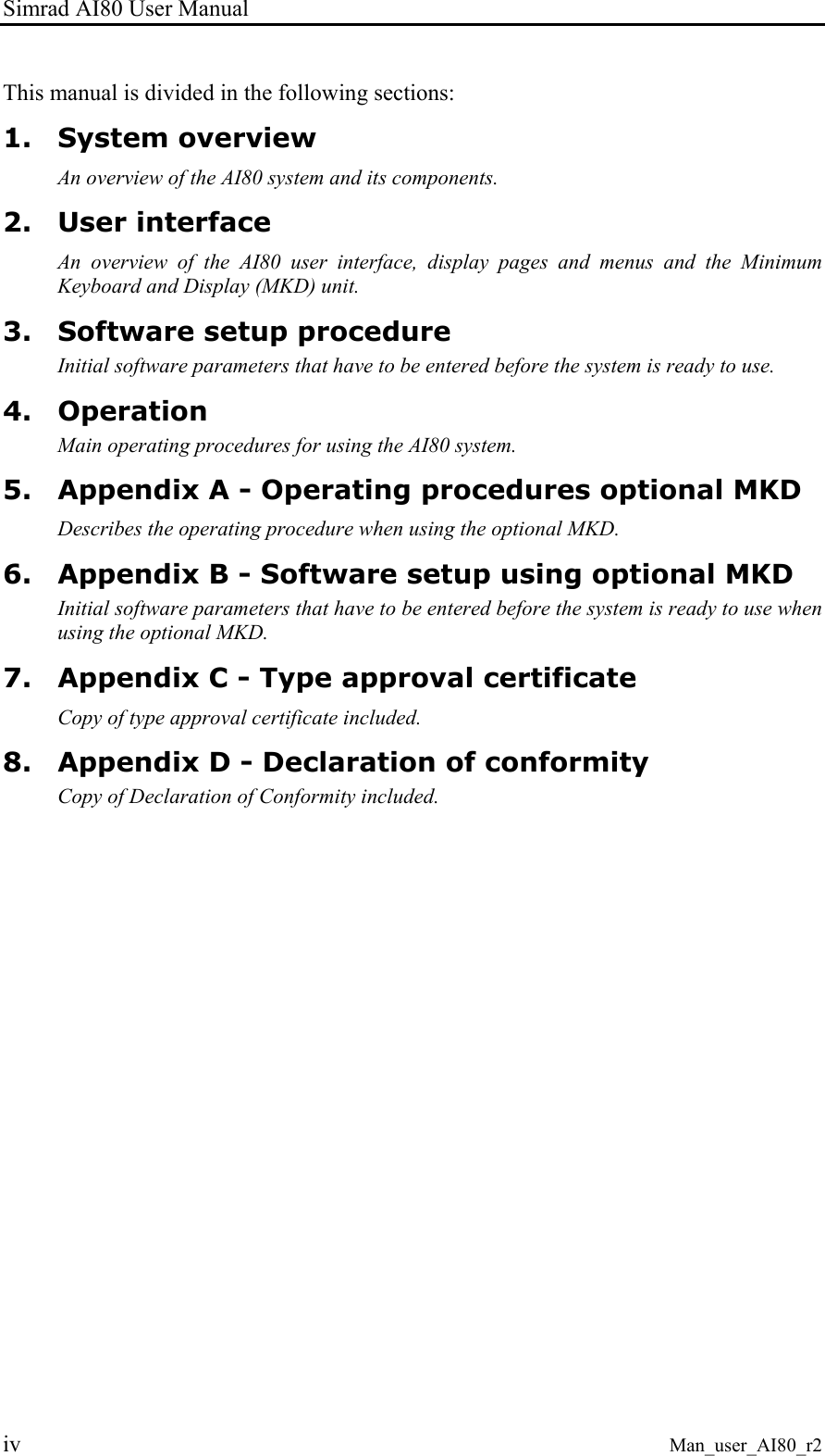
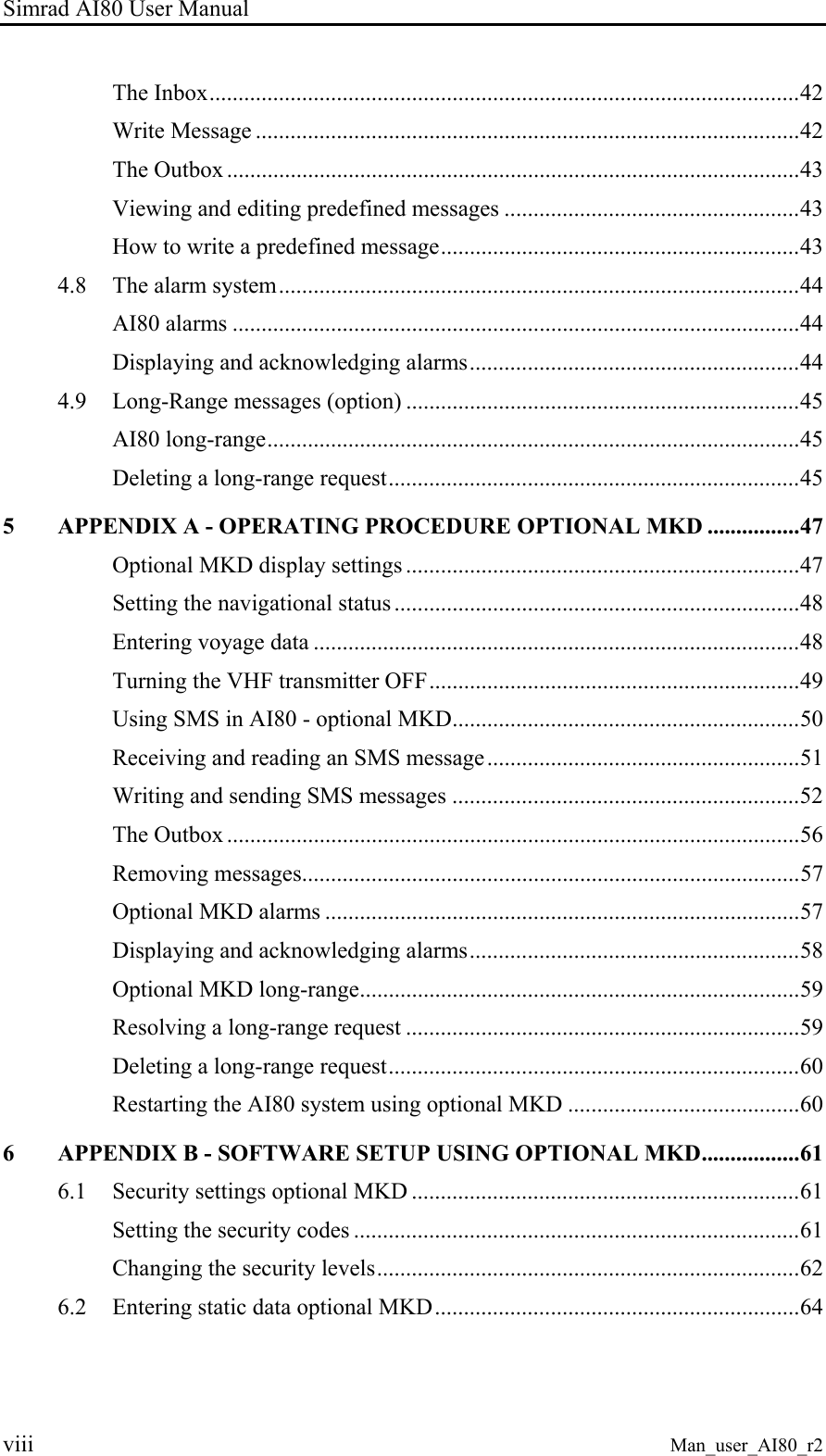
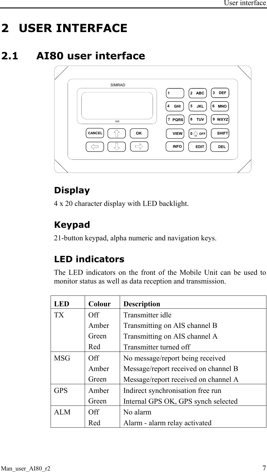
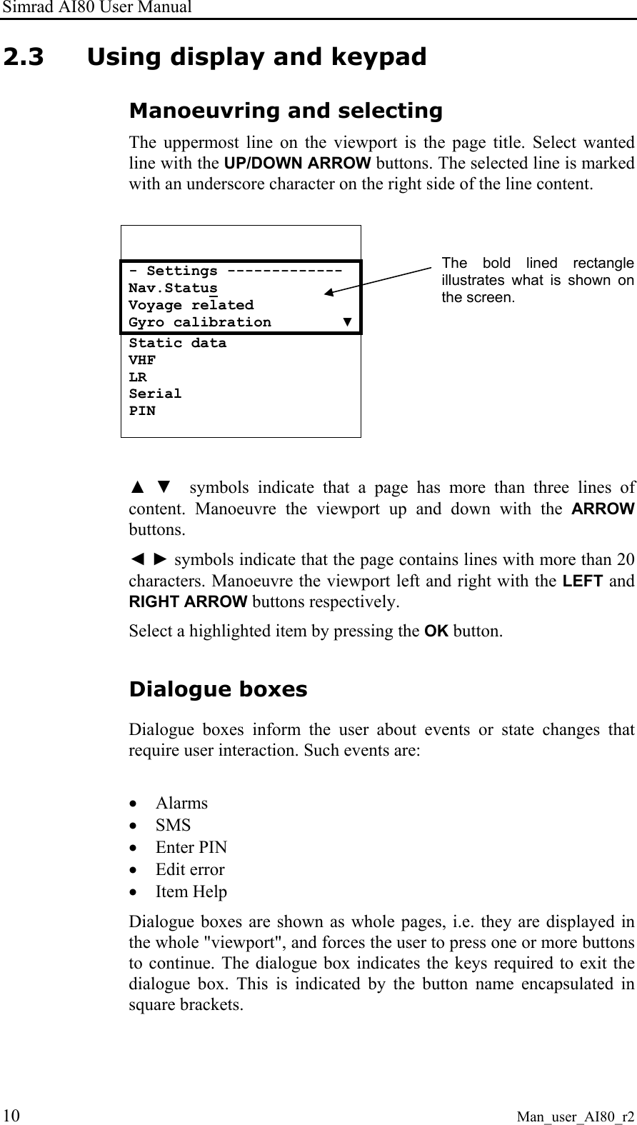
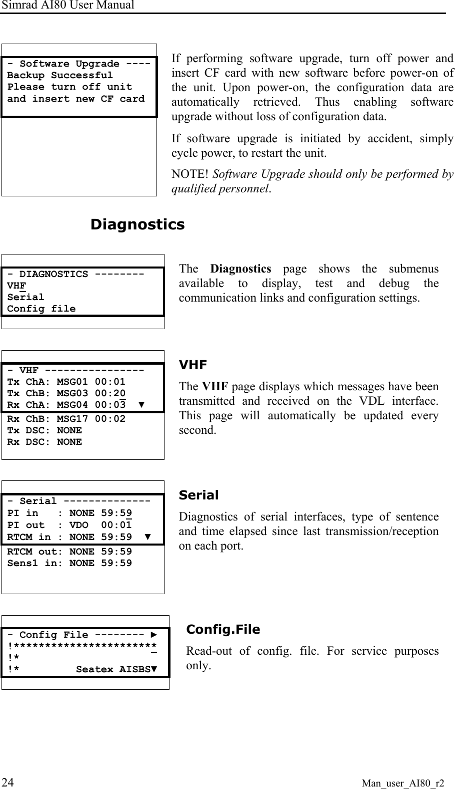
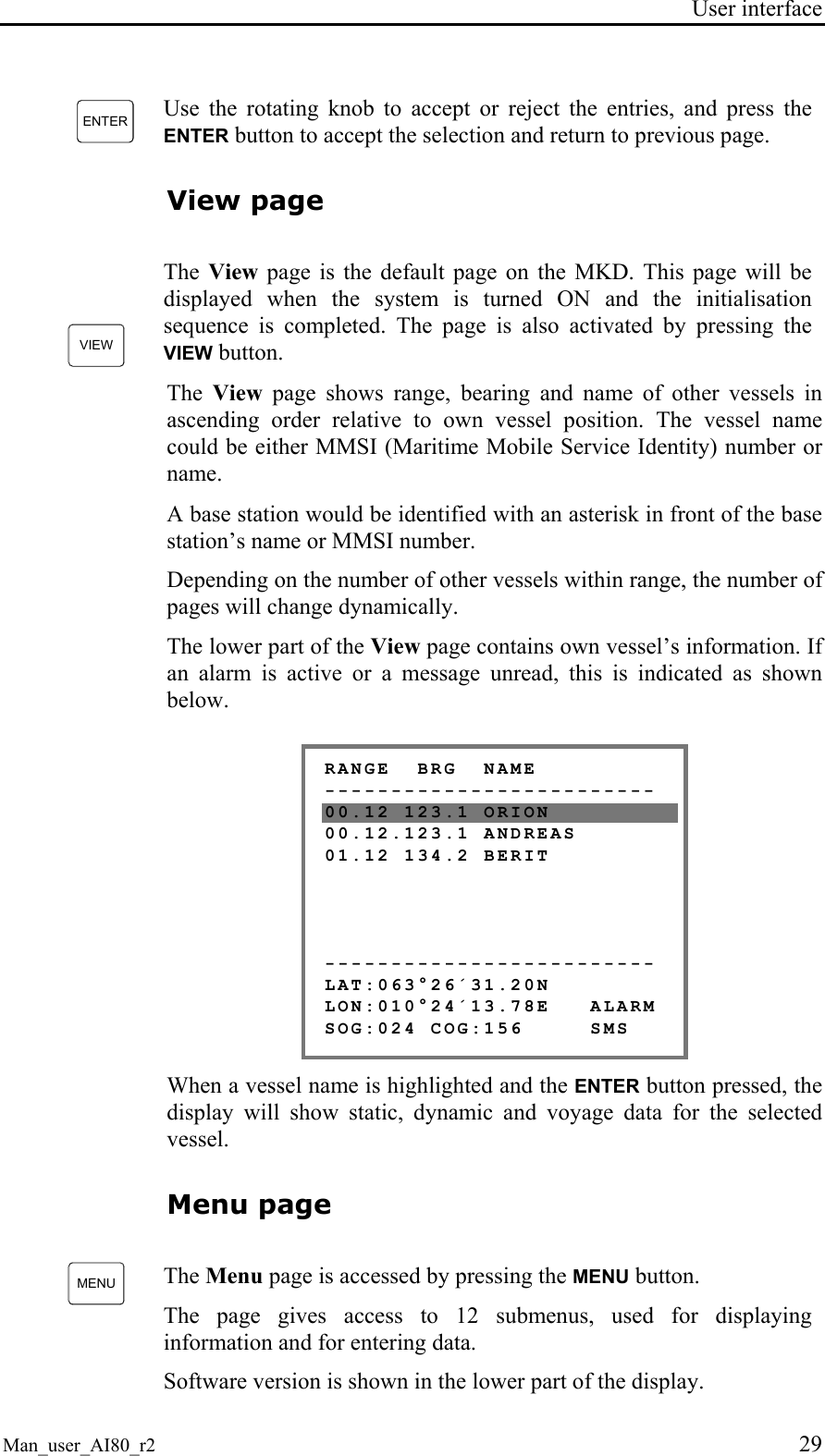
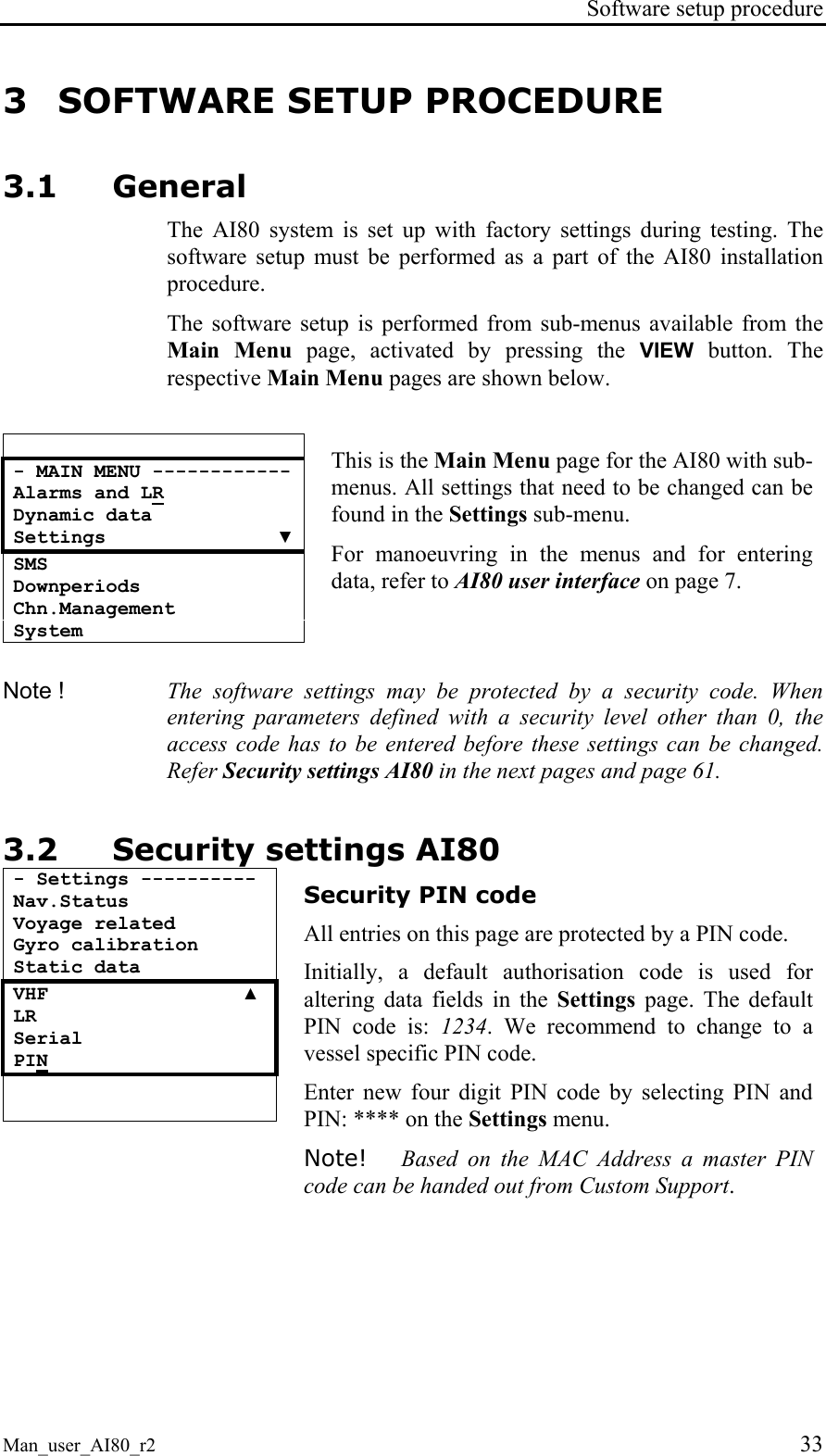
![User interface Man_user_AI80_r2 15 Main menu - MAIN MENU ------------ Alarms and LR Dynamic data Settings ▼ SMS Downperiods Chn.Management System Press VIEW to enter the Main menu. The user can select between Alarms and LR, Dynamic data, Settings, SMS, Downperiods, Chn.Management or System. Select menu with UP and DOWN ARROW buttons and enter the menu with OK. Alarms and LR Alarms and LR involves two different modes: • New Alarm/LR received • List of Alarms and List of LR *** Alarm *********** Tx Malfunction [OK] to ack New alarm When a new alarm is received, a dialogue box will appear. Press OK to acknowledge the alarm. If the alarm condition disappears before it is acknowledged, the dialogue page and the viewport is relocated to the previous page and line. As long as an alarm is active, it can be viewed by navigating to the Active alarms page. - Alarms & LR ------- Active alarms LR requests Active alarm All active alarms can be viewed under the Alarms and LR menu by selecting them and pressing OK. - Active alarms ----- Tx malfunction 11:00 VSWR exceeds 10:49 RX Chn1 malf. 10:3▼ RX Chn2 malf. 09:01 Heading Lost 08:33 No ROT info 03:42 Active alarms are listed with the latest alarm on top. This is a read only page.](https://usermanual.wiki/Kongsberg-Seatex-AS/AIS200AI80.Exhibit-8-User-Manual/User-Guide-492481-Page-25.png)
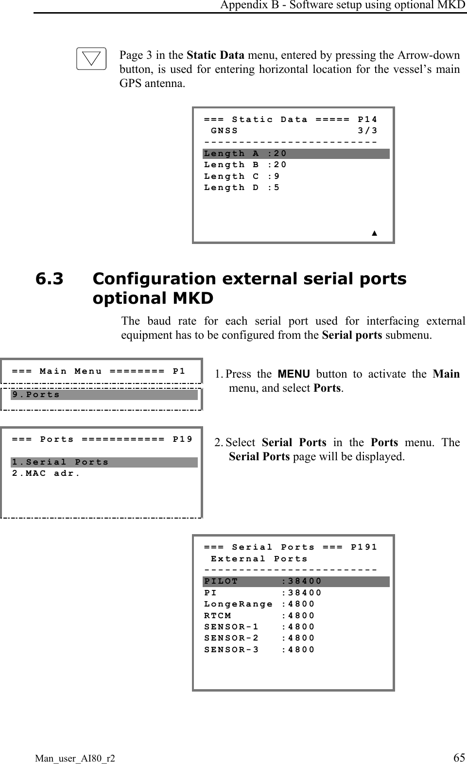
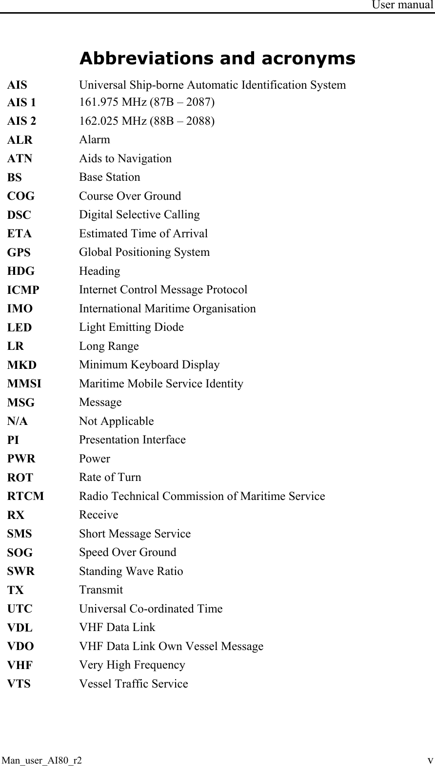
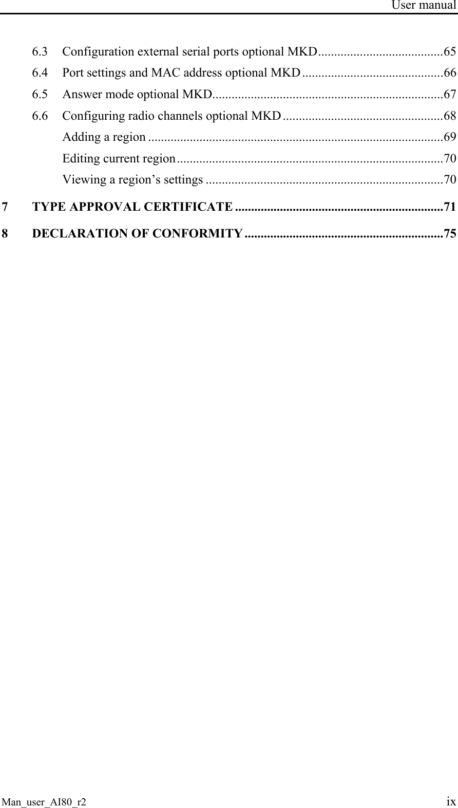
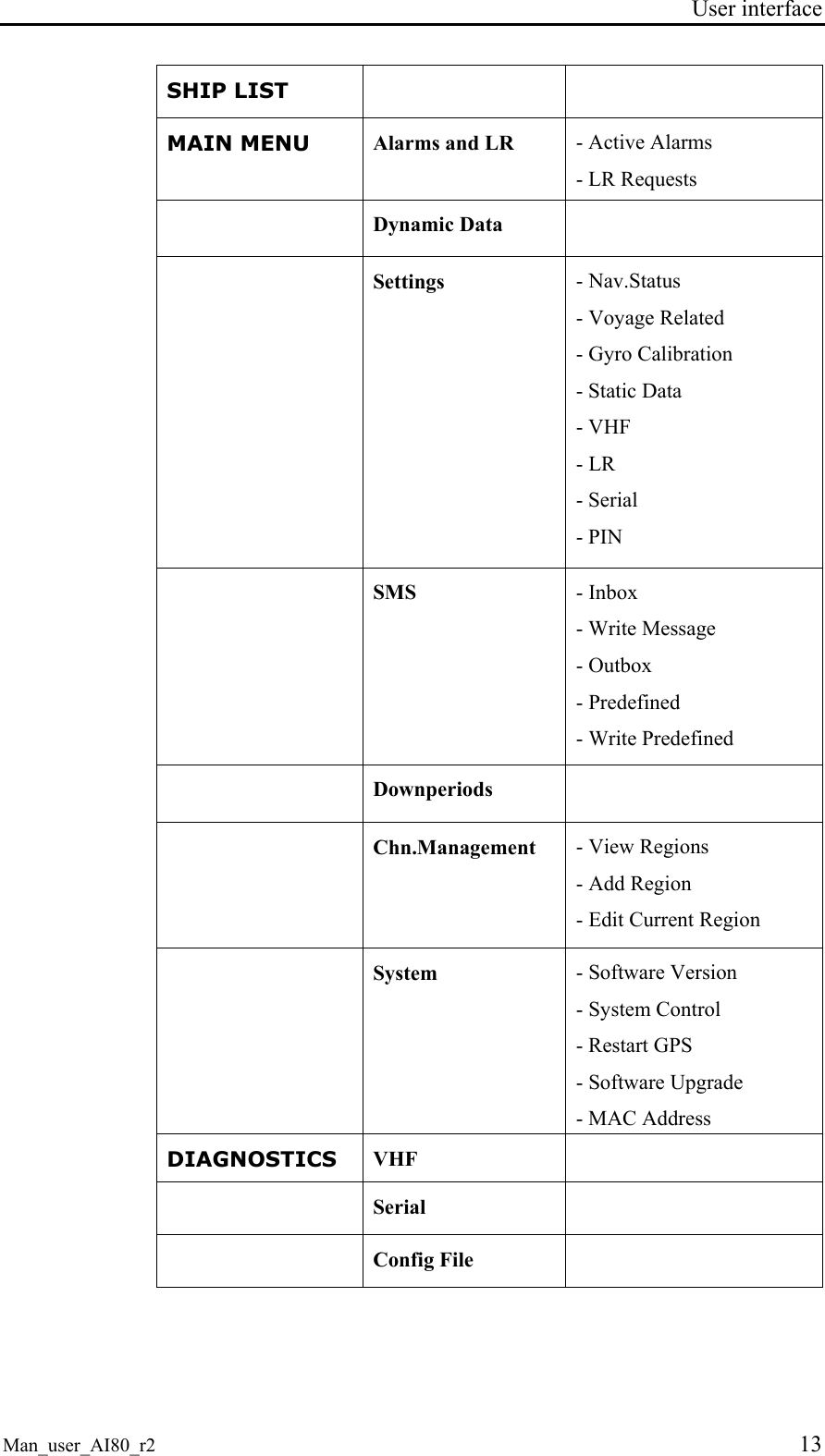
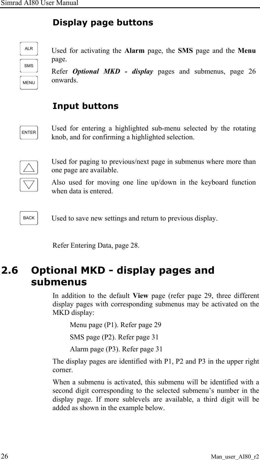
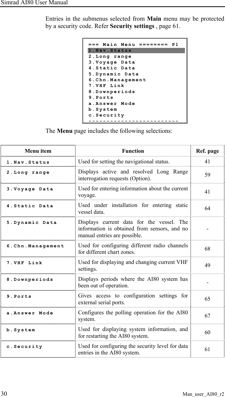
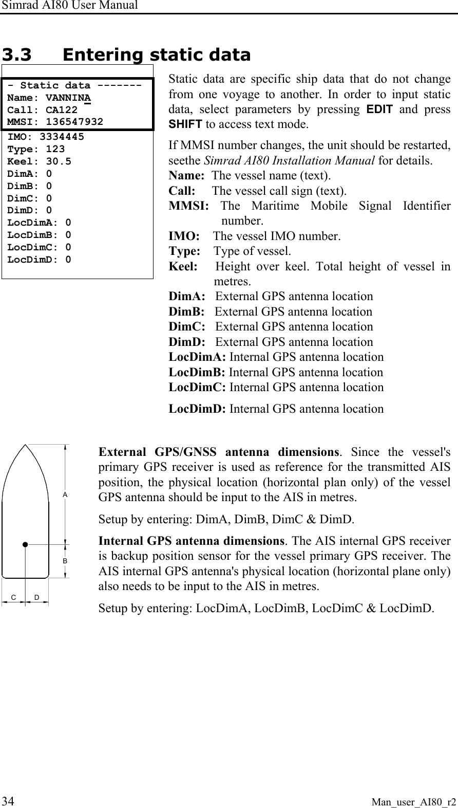
![Simrad AI80 User Manual 16 Man_user_AI80_r2 *** LR Req 123456789:ABCEFIOPUW [OK] to send [Cancel] to deny New LR When an LR request arrives, a dialogue box prompts the user to send or deny the requested information. The dialogue box provides information about requester's MMSI and the codes for requested information (e.g. C means Position). The Info functionality can describe this upon request. If the user does not respond within the given timeout, the information is denied to the requester. All LR requests are also stored in LR history. Press OK to send the information or CANCEL to reject the information. 123456789:ab - LR requests ------- 111111111: abcef ▲ 222222222: ABCEFIOPUW 333333333: a ▼ 444444444: ce 555555555: abc 666666666: ABCE 777777777: puw LR requests LR requests contains history of the last 30 requests. This is also a read only page. The figure shows a list with eight requests. First the MMSI of the requestor followed by the information requested. If the requested information is displayed with small letters, the information is provided, otherwise denied. Dynamic data - Dynamic Data ------ LAT: 063°36'31.44N LON: 010°24'13.73E COG: 000.00° ▼ SOG: 000.00kn HDG: N/A ROT: N/A EPFD: GPS The Dynamic Data page shows sensor readings. This is a read only page. Press CANCEL to return to Main Menu.](https://usermanual.wiki/Kongsberg-Seatex-AS/AIS200AI80.Exhibit-8-User-Manual/User-Guide-492481-Page-26.png)
![Simrad AI80 User Manual 18 Man_user_AI80_r2 - Static data ------- Name: VANNINA Call: CA122 MMSI: 136547932 IMO: 3334445 Type: 123 Keel: 30.5 DimA: 0 DimB: 0 DimC: 0 DimD: 0 LocDimA: 0 LocDimB: 0 LocDimC: 0 LocDimD: 0 Static data All static ship data can be viewed and altered here. If MMSI number is changed, the unit should be restarted, see chapter 4.3. - VHF --------------- TX: On VDL: Off Hold [OK] to save VHF In this page the transmission (TX) can be turned ON/OFF, and also the VDL answer mode can be set. - LR ---------------- LR Mode: MANUAL Hold [OK] to save LR In this page the LR mode can be set. Choose between Manual and Automatic. - Serial ------------ Sensor 1: 4800 Sensor 2: 4800 Sensor 3: 4800 ▼ RTCM : 4800 PI : 38400 Pilot : 38400 LR : 4800 Serial In this page the baud rate for the serial ports can be set. - PIN ---------------- PIN: **** Hold [OK] to save PIN In this page the PIN code can be changed.](https://usermanual.wiki/Kongsberg-Seatex-AS/AIS200AI80.Exhibit-8-User-Manual/User-Guide-492481-Page-28.png)
![User interface Man_user_AI80_r2 19 SMS - SMS --------------- Inbox Write Message Outbox ▼ Predefined Write Predefined In the SMS main menu the user can choose between Inbox, Write Message, Outbox, Predefined or Write Predefined. Select with UP/DOWN ARROW buttons and enter page with OK. - Inbox ------------- 122121211 29.Dec 12:39 Rasken 28.Dec 12:39 √ Tuppa 27.Dec 1▼:39 √ Bella 27.Dec 12:39 √ Joey 27.Dec 12:39 √ Elli 27.Dec 12:39 √ Barbie 27.Dec 12:39 Inbox Inbox contains received messages (max 30) with the most recent message at the top. * Message ********* This message is an inbox message [DEL] to delete ▼ [OK] for next msg [CANCEL] to close [EDIT] to reply Press UP/DOWN ARROW to select message. OK displays the message to the user. If the message is previously read, a check-sign is shown in front of that line. If the message is more than four lines, UP and DOWN are used to scroll lines. Press DEL to delete the message. Press OK to see next message without deleting. Pressing CANCEL takes the user back to the Inbox without deleting the message. - Write message ----- Channel: Default Type: Addressed Send to:----------- ▼ Predef.: NONE Message: Hold [OK] to send Write message Select Write message in the SMS menu to write a message and the following screen appears.](https://usermanual.wiki/Kongsberg-Seatex-AS/AIS200AI80.Exhibit-8-User-Manual/User-Guide-492481-Page-29.png)
![Simrad AI80 User Manual 20 Man_user_AI80_r2 Channel: Default Type: Addr SR Send to: 257999429 Predef.: NONE Message: This message is sent to the vessel - Write message ----- chosen when press ing enter ▲ Hold [OK] to send Select channel (A, B, Both, Default), type of message to send (Addressed, Addressed Safety related, Broadcast Safety related) and receiver (from list of available stations). In addition the user can choose a predefined message to appear. When all data are entered, press OK to send message as configured. - Outbox ------------- 122121211 29.Dec 12:39 √ Rasken 28.Dec 12:39 √ Tuppa 27.Dec 1▼:39 √ Bella 27.Dec 12:39 √ Joey 27.Dec 12:39 √ Elli 27.Dec 12:39 √ Barbie 27.Dec 12:39 Outbox Outbox contains all sent messages. If the receiver acknowledged the message, a check-sign is shown in front of that line. The latest message is on top. If the user wants to re-send or read a message, select message with UP/DOWN and press OK. The page shown in the figure is displayed. - Message ------------ This message is an outbox message [DEL] to delete ▼ [OK] for next msg [CANCEL] to close [EDIT] to resend Selecting EDIT resends the message with the same parameters as last time. - Predefined --------- Happy Day Happy Easter Merry Christmas ▼ Happy New Year Happy Holiday Predefined messages In this page the user can edit, view or delete a previously defined message. Press OK to view or edit a message, press DEL to delete a message. Reading a predefined message has the same functionality as reading a message in Inbox, except that EDIT allows the user to edit the predefined message.](https://usermanual.wiki/Kongsberg-Seatex-AS/AIS200AI80.Exhibit-8-User-Manual/User-Guide-492481-Page-30.png)
![User interface Man_user_AI80_r2 21 - Write predef. ------- Name: Message: Hold [OK] to save Write predefined In the Write predefined page only the required data are available for entry, e.g. the name of the predefined message and the message text. *** NEW SMS *********** 4 unread messages [OK] go to Inbox [CANCEL] later New SMS received When an SMS is received, the user is notified through a dialogue box that appears on the screen. Press OK to read the message immediately or LEFT ARROW to delete the dialogue box. The message can be found in Inbox. Downperiods - Downperiods ---- ► 23.May 08:00 - 23.May 08:30 23.May 09:00 - 23.May 09:30 23.May 10:00 - 23.M▼y 10:30 23.May 11:00 - 23.May 11:30 23.May 12:00 - 23.May 12:30 This page shows the last ten downtimes (start and stop) for the Base Station on the format DD/MM hh:mm - DD/MM hh:mm. It is a read only page. Press CANCEL to return to Main Menu. Channel Management - Chn.Mngt --------- View Regions Add Region Edit Current region In the Chn. management menu the user can choose between editing current region, viewing all regions or adding a new region. - Regions ----------- REGION 1 REGION 2 REGION 3 ▼ REGION 4 View regions In this page all regions (max 8) are shown. This is a read only page. Use UP/DOWN ARROW to select the region of interest. The figure shows a list with three regions.](https://usermanual.wiki/Kongsberg-Seatex-AS/AIS200AI80.Exhibit-8-User-Manual/User-Guide-492481-Page-31.png)
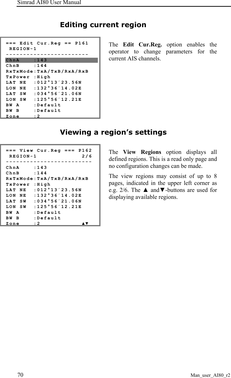
![Simrad AI80 User Manual 22 Man_user_AI80_r2 - Region 2 ---------- ChnA: 2087 ChnB: 2088 RxTx: TxA/TxB, RxA/Rx▼ TxPower: LOW LAT NE: 64°00'00.00N LON NE: 011°00'00.00E LAT SW: 00°00'00.00N LON SW: 000°00'00.00E BW A: Default BW B: Default Zone: 0 Hold [OK] to save Region In this page the selected region is displayed. This page is read only and shows each region's parameters. - Add region --------- ChnA: 0 ChnB: 0 RxTx: TxA/TxB, RxA/Rx▼ TxPower: LOW LAT NE: 00°00'00.00N LON NE: 000°00'00.00E LAT SW: 00°00'00.00N LON SW: 000°00'00.00E BW A: Default BW B: Default Zone: 0 Hold [OK] to save Add region In this page the user can add a region manually. Refer chapter 3.6. - Default Values ---- ChnA: 0 ChnB: 0 TxPower: HIGH ▼ BW A: Default BW B: Default Hold [OK] to save Edit Current region In this page the user can edit current region settings. Select parameter with UP/DOWN, press EDIT to start editing and OK when finished. Hold OK button to save changes to region. If the user presses CANCEL, he is informed that cancelling will delete his entered region. If the region entered is not a valid region, the user is notified about this through a dialogue box.](https://usermanual.wiki/Kongsberg-Seatex-AS/AIS200AI80.Exhibit-8-User-Manual/User-Guide-492481-Page-32.png)
![User interface Man_user_AI80_r2 23 System - System ------------ Software version System control Reset GPS ▼ Software Upgrade MAC Address From the System page the user can see the current software version, restart the unit, reset the internal GPS receiver, upgrade the software and view the MAC Address. - SW version---------- Version: 4.00.00 This is a read only page for information purposes only. - System control------ Restart unit If a system restart is required, select Restart unit and press OK. The unit will now initiate the restarting process. - Restart GPS -------- Restart GPS If GPS tracking problems are experienced, restarting the GPS may solve these problems. - MAC Address -------- MSB: 000.005.190 LSB: 000.005.200 In this page the MAC Address is viewed. This is a read only page. - Software Upgrade ---- Start Upgrade Hold [OK] to start When pressing OK on this page, the configuration data are stored for later retrieval. The unit enters an SW upgrade mode where no other activities are performed until power is cycled.](https://usermanual.wiki/Kongsberg-Seatex-AS/AIS200AI80.Exhibit-8-User-Manual/User-Guide-492481-Page-33.png)
![User interface Man_user_AI80_r2 25 Pin code protection The functionality in the mobile unit is protected by a PIN code. If the user wants to edit a protected variable, e.g. Tx On/Off, he is presented with a dialogue box. The default pin code for AI80 is 1234. *** PIN CODE ******** ** [Cancel] [OK] Use numeric buttons to write PIN code, press OK to confirm. If the PIN code is correct, the user can start editing the variable. If incorrect code is entered, a dialogue box prompting the user to retry, is presented. *** Wrong PIN ******* [OK] to try again [Cancel] to cancel Press OK to retry or CANCEL to cancel. 2.5 Optional MKD unit The MKD unit includes the following elements: VIEWALRSMSMENUBACK ENTERSIMRAD AI70 Display The display presents information pages and menus used for data input. Refer Optional MKD - display pages and submenus, page 26. Rotating knob The rotating knob is used for highlighting the different menu items on the display. ROTATING KNOB INPUT BUTTONS DISPLAY DISPLAY PAGE BUTTONS](https://usermanual.wiki/Kongsberg-Seatex-AS/AIS200AI80.Exhibit-8-User-Manual/User-Guide-492481-Page-35.png)
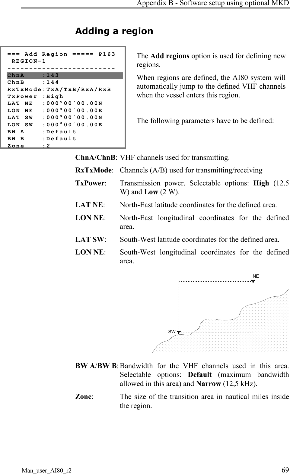
![Simrad AI80 User Manual 36 Man_user_AI80_r2 Adding a region - Add region --------- ChnA: 0 ChnB: 0 RxTx: TxA/TxB, RxA/Rx▼ TxPower: LOW LAT NE: 00°00'00.00N LON NE: 000°00'00.00E LAT SW: 00°00'00.00N LON SW: 000°00'00.00E BW A: Default BW B: Default Zone: 0 Hold [OK] to save To edit these parameters, use the ARROW buttons to manoeuvre to the parameter of interest and press EDIT. Use the DEL button if necessary, and enter the new value. If non-digits are required, press the SHIFT button to change to alpha mode. Press the SHIFT button again to return to digit mode. While in alpha mode, letters and special characters can be entered (e.g. the degree symbol °). Note ! If the user tries to enter a region which parameters locates the region more than 500 nautical miles away from the vessel, the region will automatically be discarded. Also when the vessel position is further than 500 nautical miles from the region, this region is automatically discarded by the AIS unit. ChA: The radio channel to be used as channel A. ChB: The radio channel to be used as channel B. RxTx: Transmission/reception mode. This parameter indicates whether or not the AIS should transmit and receive on both channels, or on only a subset of these. TxPower: The transmission power of the radio. Low equals 2W, and High equals 12W. Lat/Lon: The rectangular area to which the radio parameters apply. The area is specified by entering the coordinates for the north-east corner and the south-west corner. BW A: Bandwidth for the selected channel A. BW B: Bandwidth for the selected channel B. Zone: Transition zone for the region. This parameter is given in nautical miles, and provides information about the transition zone of the region in which the AIS should change radio parameters to the ones specified for the region.](https://usermanual.wiki/Kongsberg-Seatex-AS/AIS200AI80.Exhibit-8-User-Manual/User-Guide-492481-Page-46.png)

![Simrad AI80 User Manual 42 Man_user_AI80_r2 4.7 Using the AI80 message system The AI80 system includes an SMS function, making it possible to send text message to other vessels or to shore based stations. Using SMS in AI80 All SMS functions are selected from the SMS page, activated by selecting SMS in the Main Menu. New SMS received *** NEW SMS ********* 4 unread messages [OK] go to Inbox [CANCEL] later When an SMS is received, the user is notified through a dialogue box that appears on the screen. Press OK to read the message immediately or LEFT ARROW to delete the dialogue box. The message can be found in the Inbox. See page 19 onwards for more SMS dialogue boxes. The Inbox The user can enter the Inbox by pressing OK on the New SMS received dialogue or by entering the SMS menu under Main Menu and selecting Inbox. Press UP/DOWN ARROW to select message. OK displays the message to the user. If the message is previously read, a check-sign is shown in front of that line. If the message is more than four lines, UP and DOWN are used to scroll lines. Press DEL to delete the message. Press OK to see next message without deleting. Pressing CANCEL takes the user back to Inbox without deleting the message. Write Message Select Write Message in the SMS menu and press OK. This allows the user to prepare a message for transmission to another vessel. Select channel for transmission (A, B, Both, Default), type of message to send (Addressed, Addressed Safety related, Broadcast Safety related) and receiver (from list of available stations). In addition the user can choose a predefined message to appear. If a predefined message is not used, the user can enter a specific message after Message. Enter a message by pressing EDIT and the cursor starts to](https://usermanual.wiki/Kongsberg-Seatex-AS/AIS200AI80.Exhibit-8-User-Manual/User-Guide-492481-Page-52.png)
![Simrad AI80 User Manual 44 Man_user_AI80_r2 4.8 The alarm system The AI80 system does not include an internal acoustic alarm. It is, however, possible to connect an external alarm to the system. See the Simrad AI80 Installation Manual for details. AI80 alarms *** Alarm *********** AIS: external EPFS Lost [OK] to ack If an alarm situation occurs, the Alarm menu will appear and display the latest alarm. This alarm will be displayed until it is acknowledged by pressing the OK button or the alarm condition ceases to exist. If further alarms exist, they will be displayed in turn, starting with the latest. As long as there are unacknowledged alarms, the ALM LED will be red and the alarm relay will engage, see the Simrad AI80 Installation Manual. Displaying and acknowledging alarms - Alarms & LR ------- Active Alarms LR requests In the Main Menu there is an entry for Alarms & LR. By selecting it, the user can select between viewing active alarms and LR requests. - Active Alarms Ext.epfs lost √ Heading lost √ No valid rot √ By selecting the Active Alarms entry, the user can view all active alarms registered in the AIS unit. A check mark after the alarm indicates that the alarm has been acknowledged.](https://usermanual.wiki/Kongsberg-Seatex-AS/AIS200AI80.Exhibit-8-User-Manual/User-Guide-492481-Page-54.png)
![Operation Man_user_AI80_r2 45 4.9 Long-Range messages (option) The AI80 contains a long-range interface for connection to an external communication system like Inmarsat. If long-range equipment is included in the system, it is possible to poll AIS system data from anywhere within the Inmarsat coverage area. AI80 long-range *** LR-inquiry ****** VTS: ABCEFIOPW [OK] to send [CANCEL] to reject Upon a reception of an LR inquiry, the LR inquiry menu appears. It contains the name of the inquirer and the function request string. By pressing the OK button the AIS unit responds to the inquiry and by pressing CANCEL the AIS unit sends a rejection message to the inquirer. - Alarms & LR ------ Active Alarms LR requests To view a list of all the long-range inquiries that have been received, access the Main Menu and enter the Alarms & LR option. - LR Answers -------- √ VTS: ABCEFIOPW √ HECTOR: ABC √ VTS: ABCEF ▼ [Hold OK] Clear all Under LR requests there is a complete list of all LR requests (inquiries). The check mark before the name of the inquirer indicates that the request has been processed. Deleting a long-range request By holding the OK button pressed, the LR list will be cleared.](https://usermanual.wiki/Kongsberg-Seatex-AS/AIS200AI80.Exhibit-8-User-Manual/User-Guide-492481-Page-55.png)
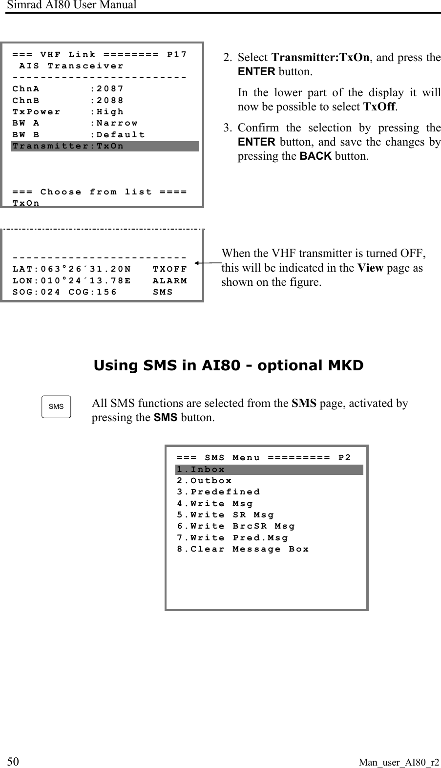
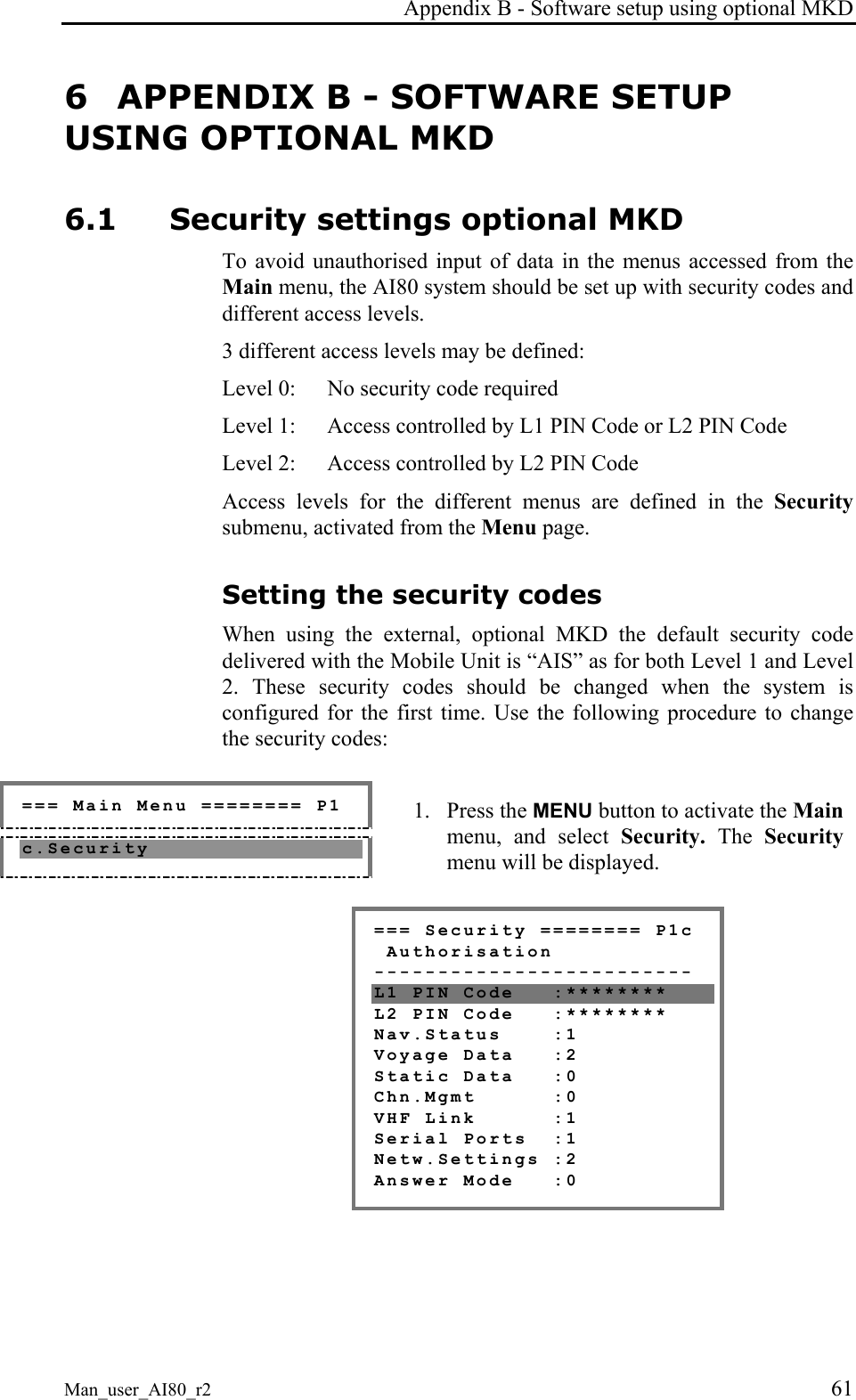
![Appendix A - Operating procedure optional MKD Man_user_AI80_r2 49 === Voyage Data ===== P13 Own Ship ------------------------- Dest :STAVANGER ETA :05172245 Drght :120 OnBrd :15 The following information should be entered: Dest: Voyage destination ETA: Estimated time of arrival, entered as month, day, hour and minutes (MMDDHHmm) Drght: Vessel draught [1/10 m] OnBrd: Total number of people on board Enter voyage data as described in Entering Data, page 28. Activate the setting by pressing the BACK button. Turning the VHF transmitter OFF === Main Menu ======== P1 7.VHF Link 1. Press the MENU button to activate the Main menu, select VHF Link and press the ENTER button. The VHF Link page will be displayed, showing current VHF settings.](https://usermanual.wiki/Kongsberg-Seatex-AS/AIS200AI80.Exhibit-8-User-Manual/User-Guide-492481-Page-59.png)