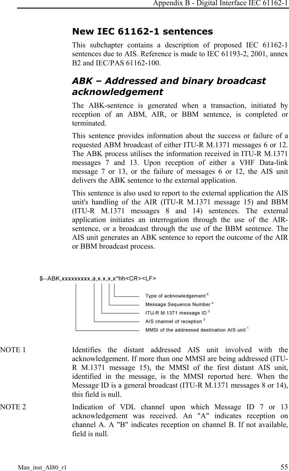
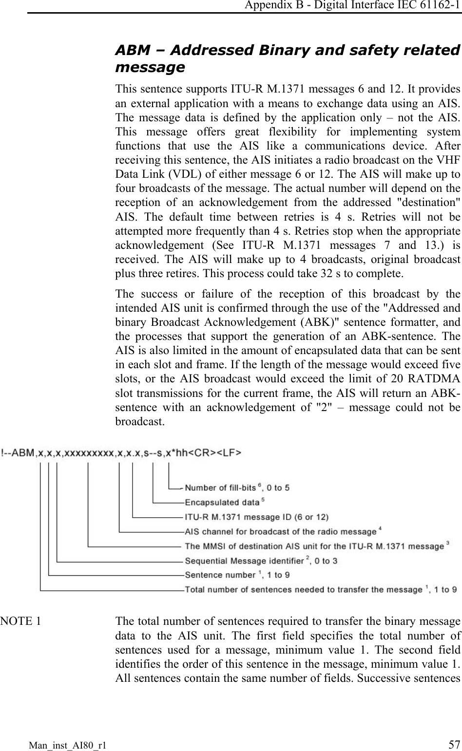
Kongsberg Seatex AS AIS200AI80 AIS200 Simrad AI80 User Manual Man inst ai80 r1 not finished

Kongsberg Seatex AS AIS200 Simrad AI80 Man inst ai80 r1 not finished

Contents

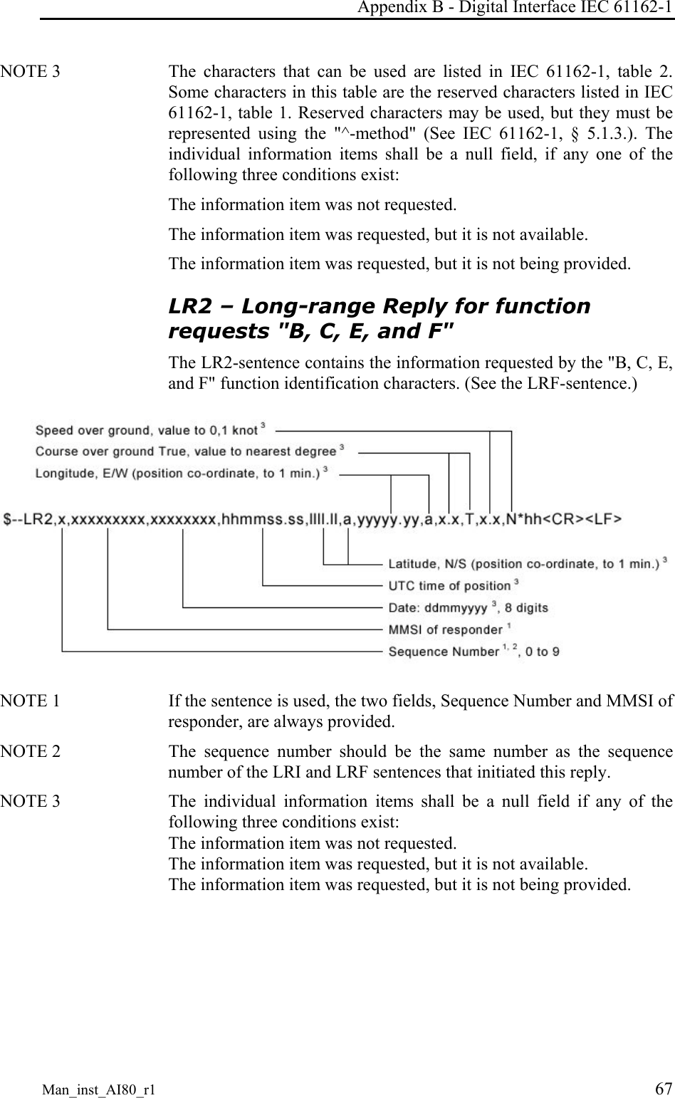
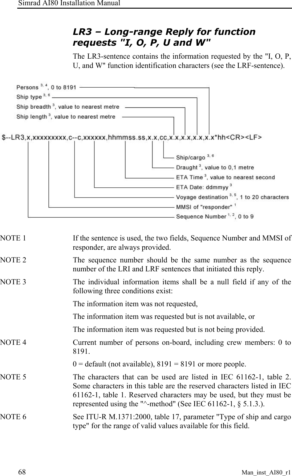
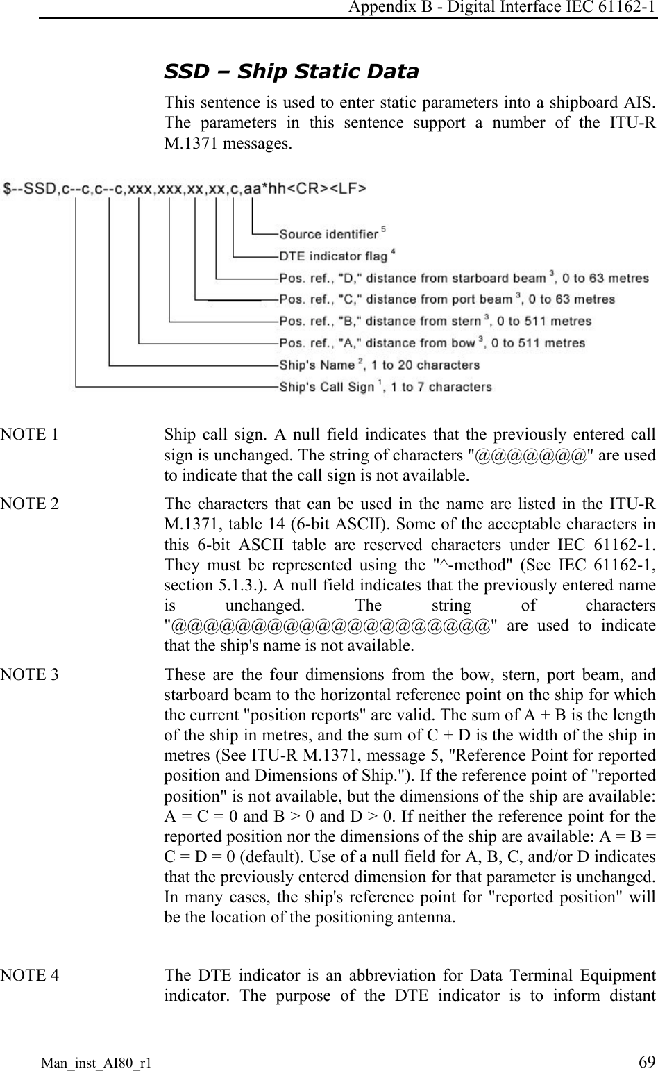
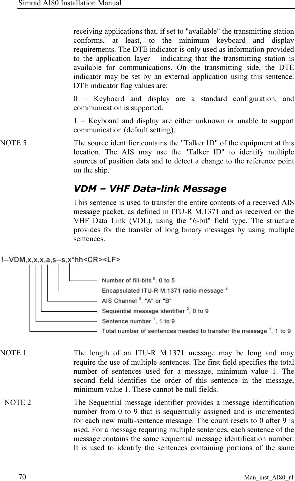
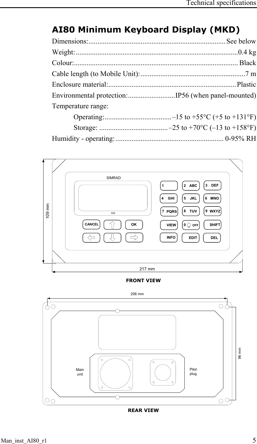
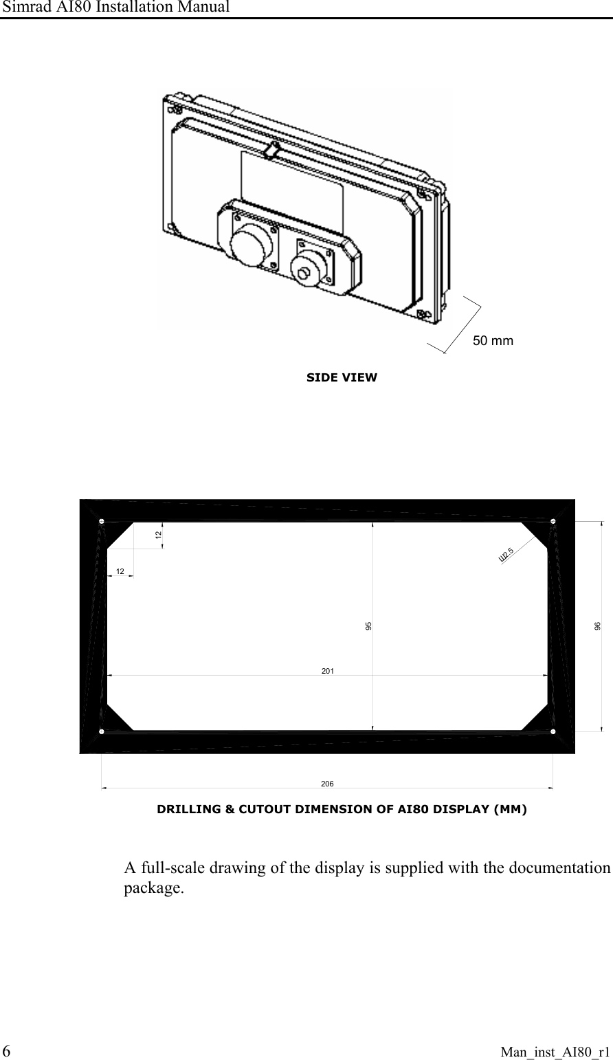
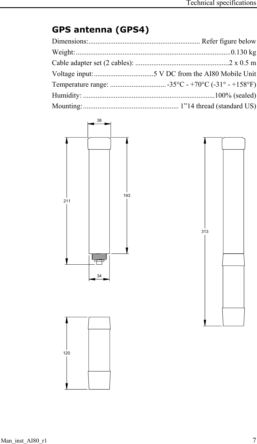
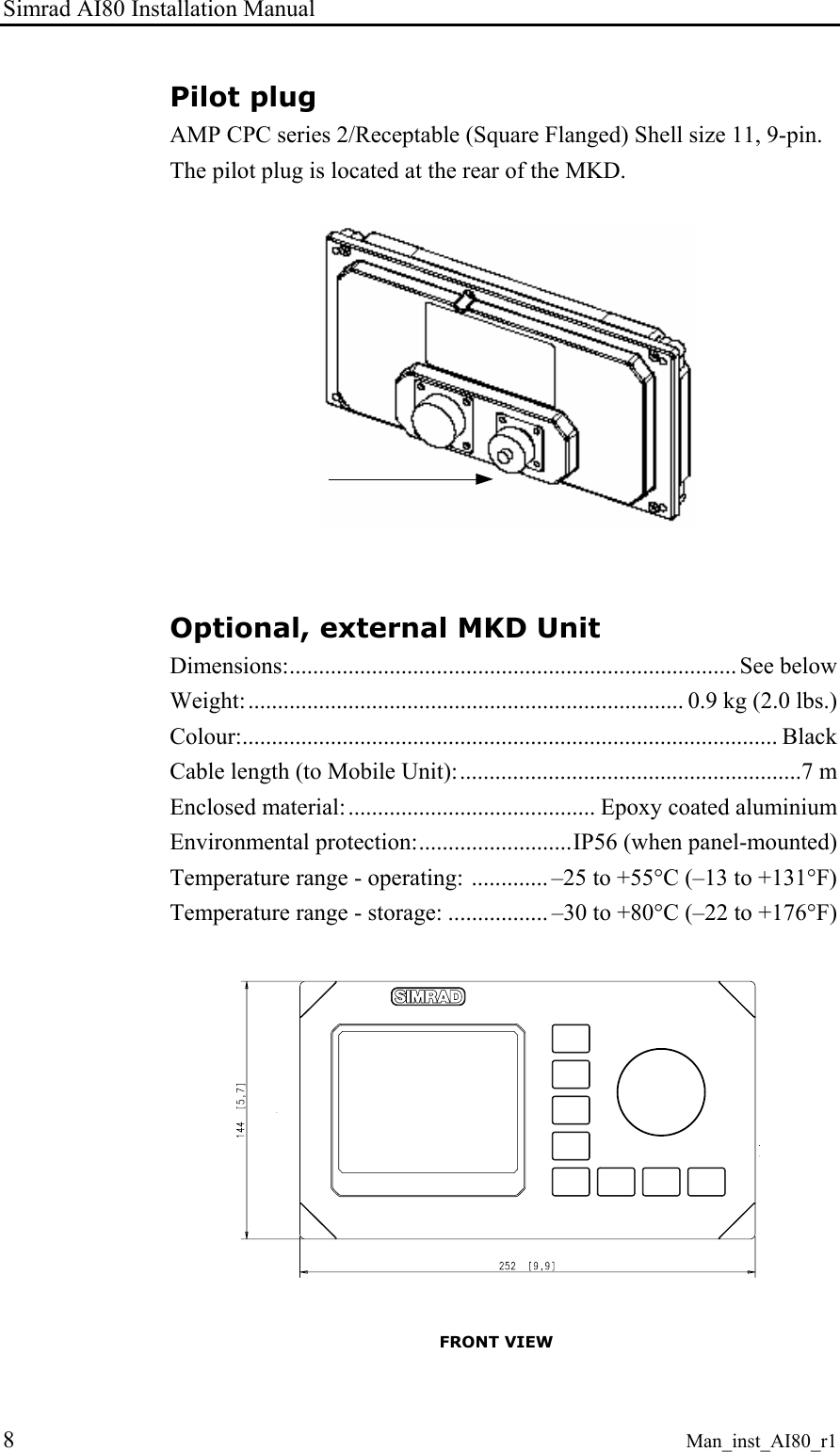
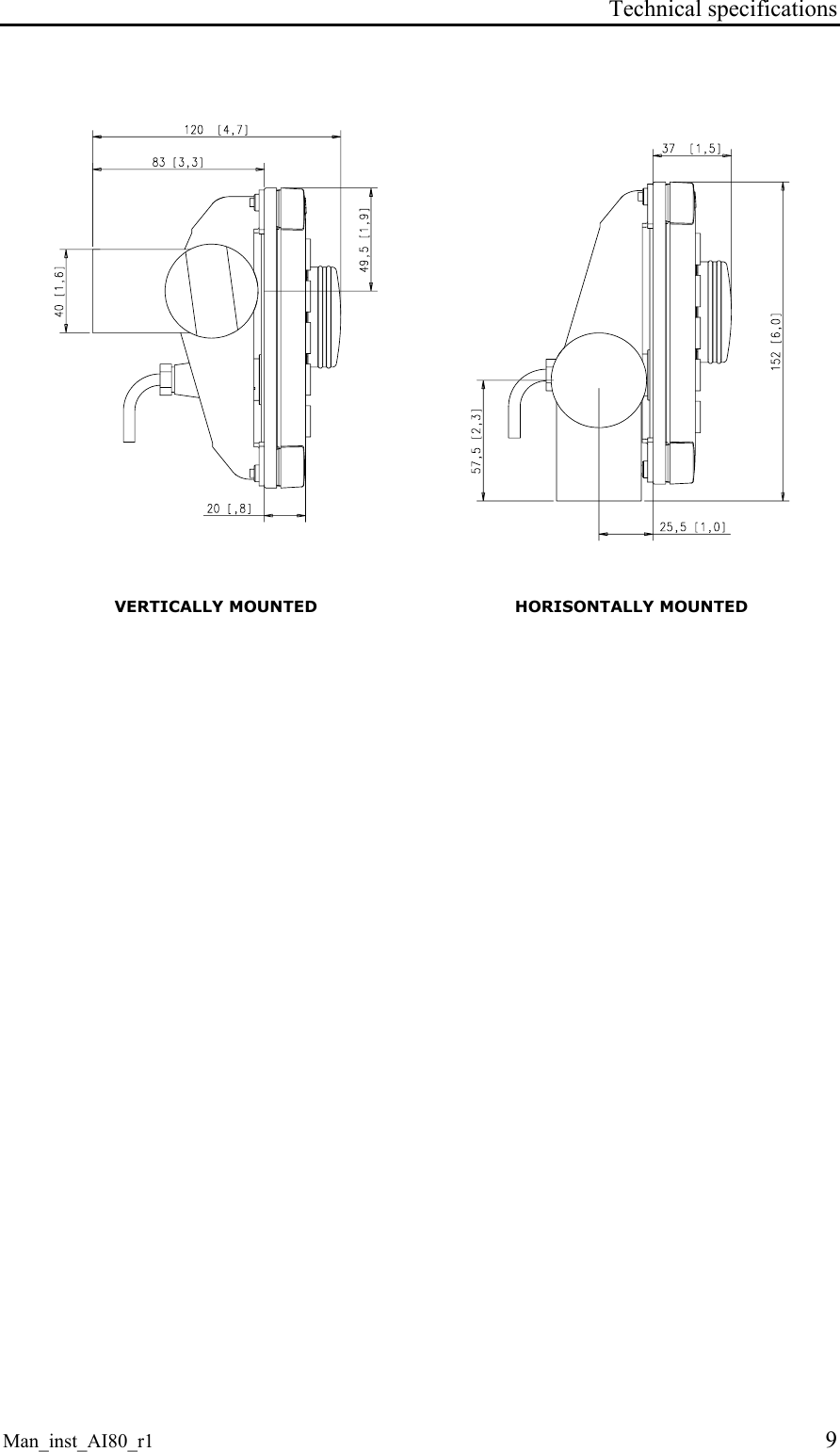
Exhibit 8 Installation Guide
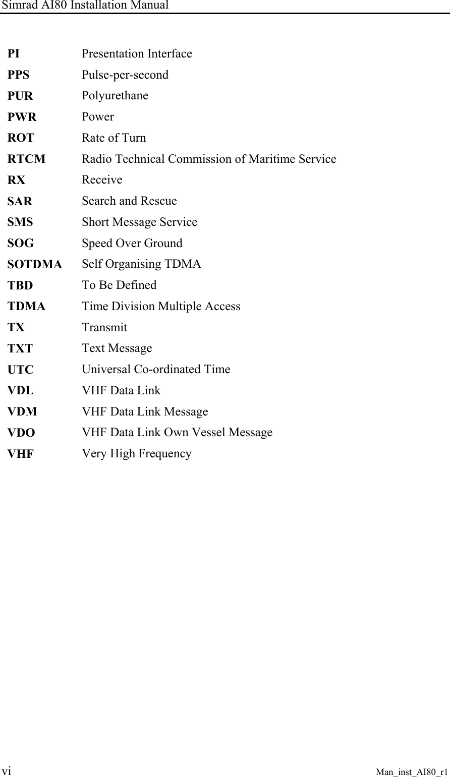
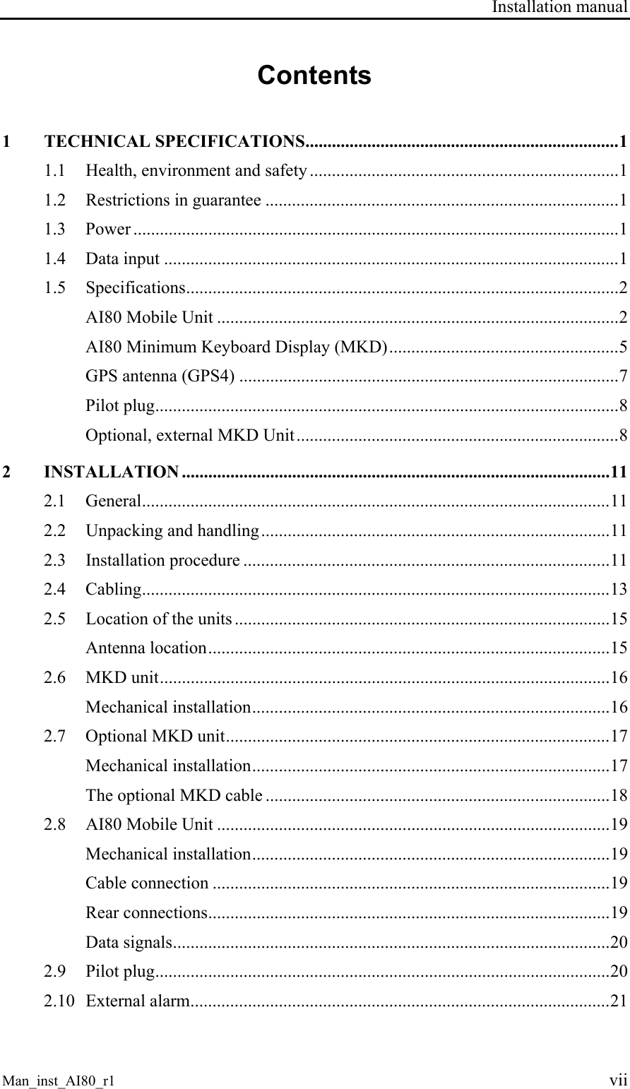
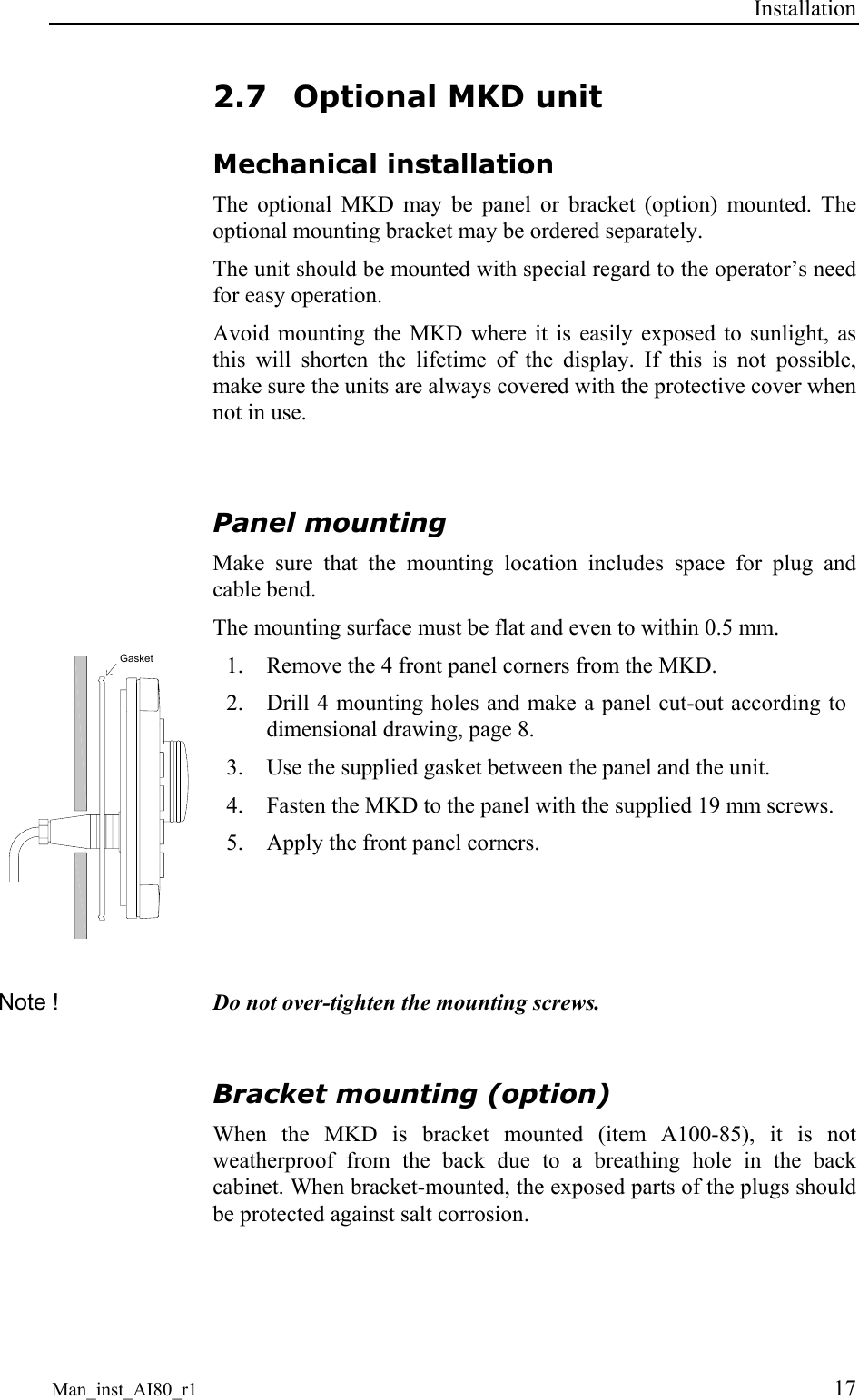
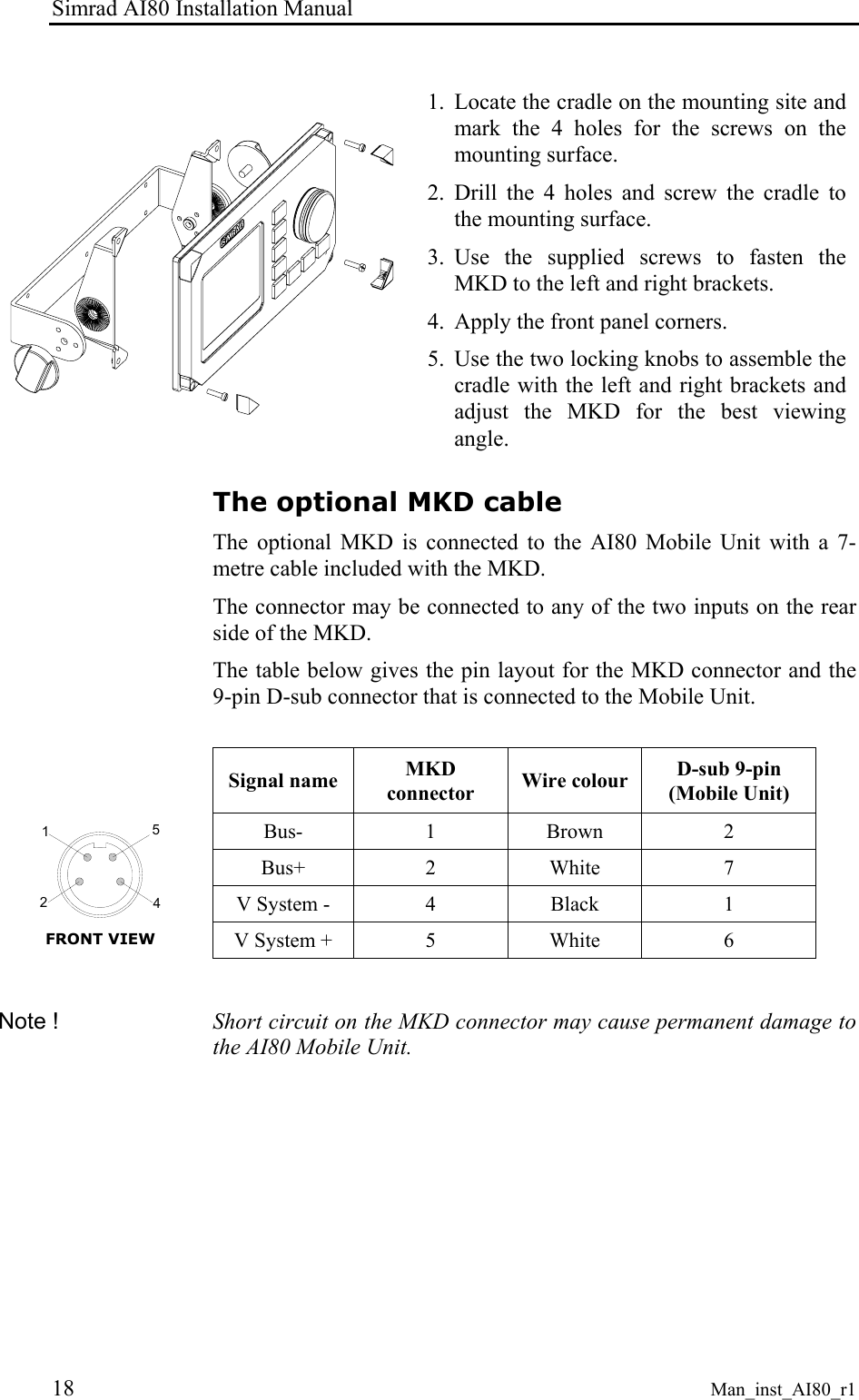
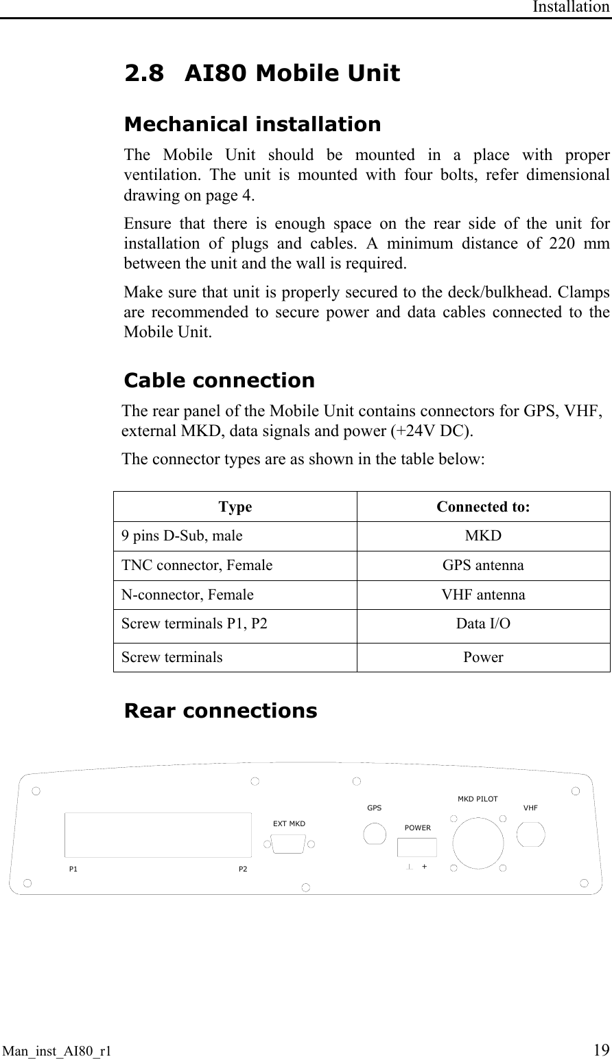
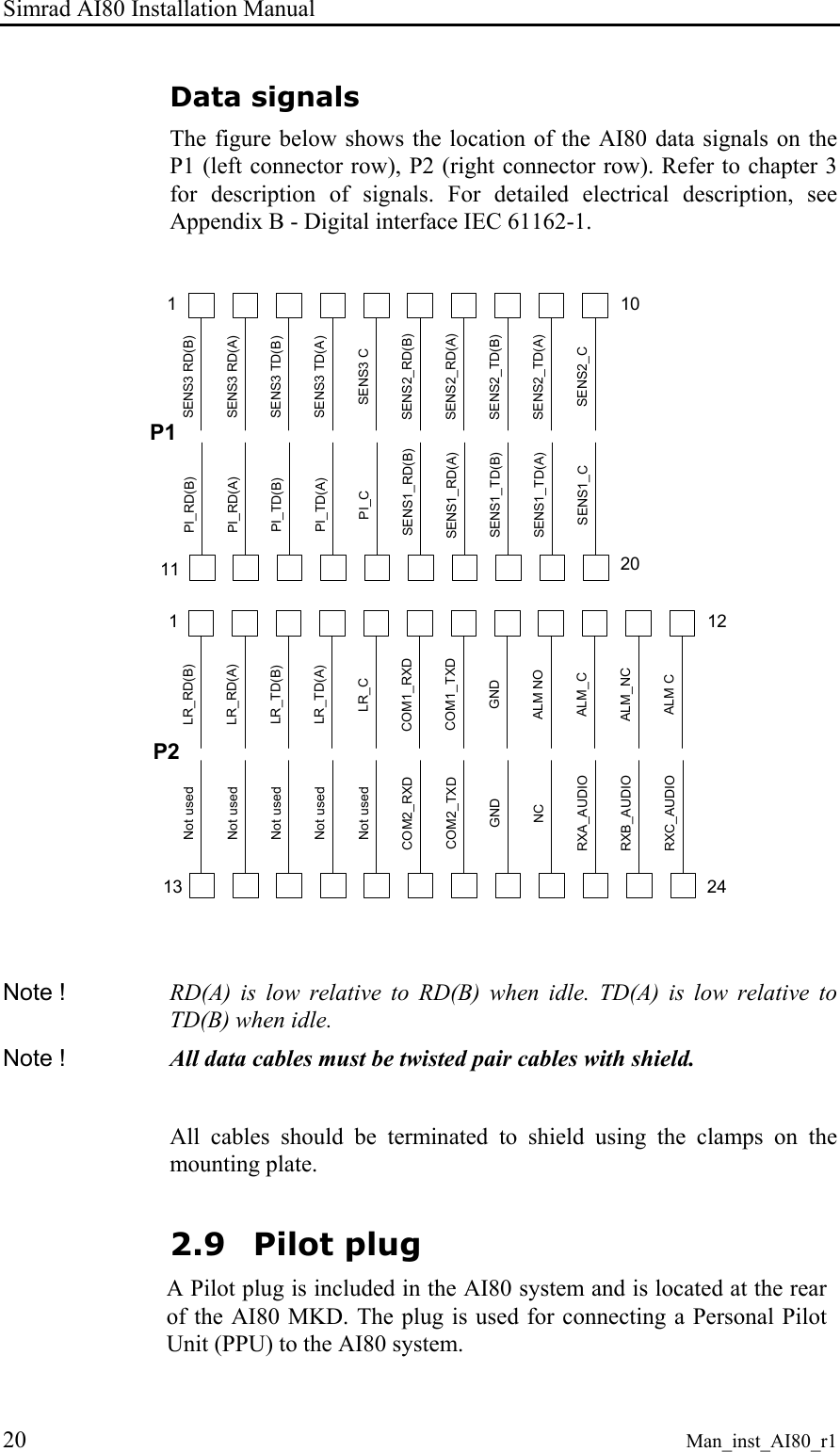
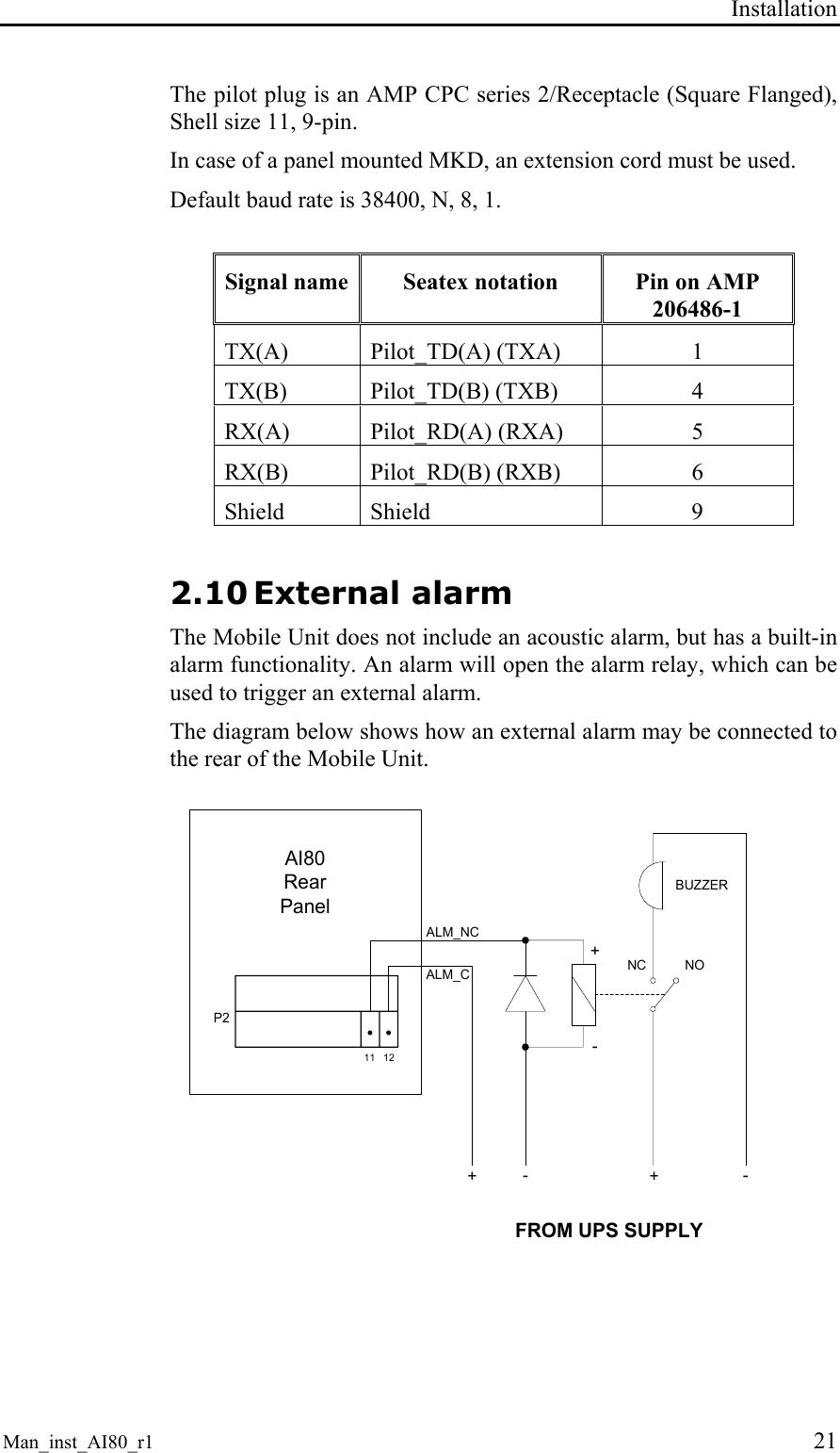
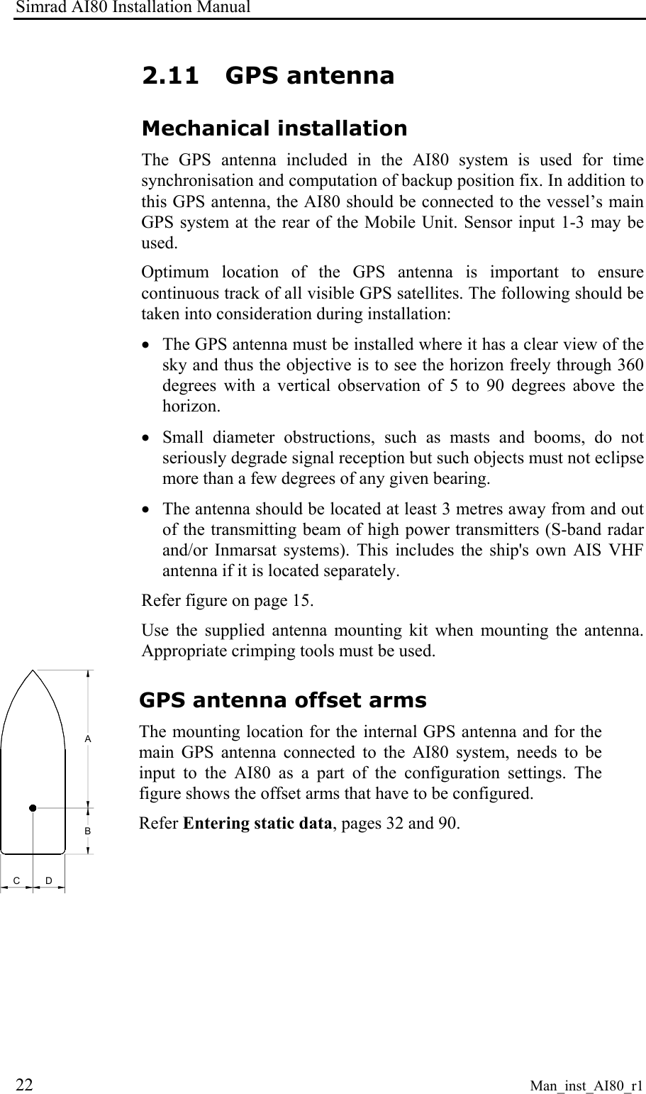
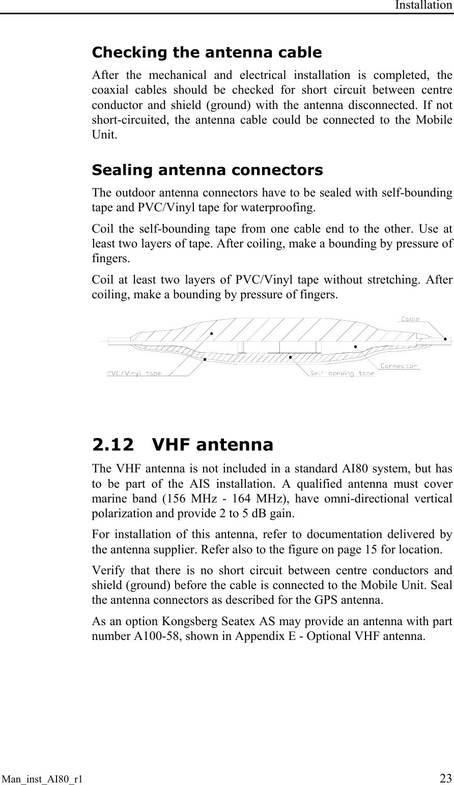
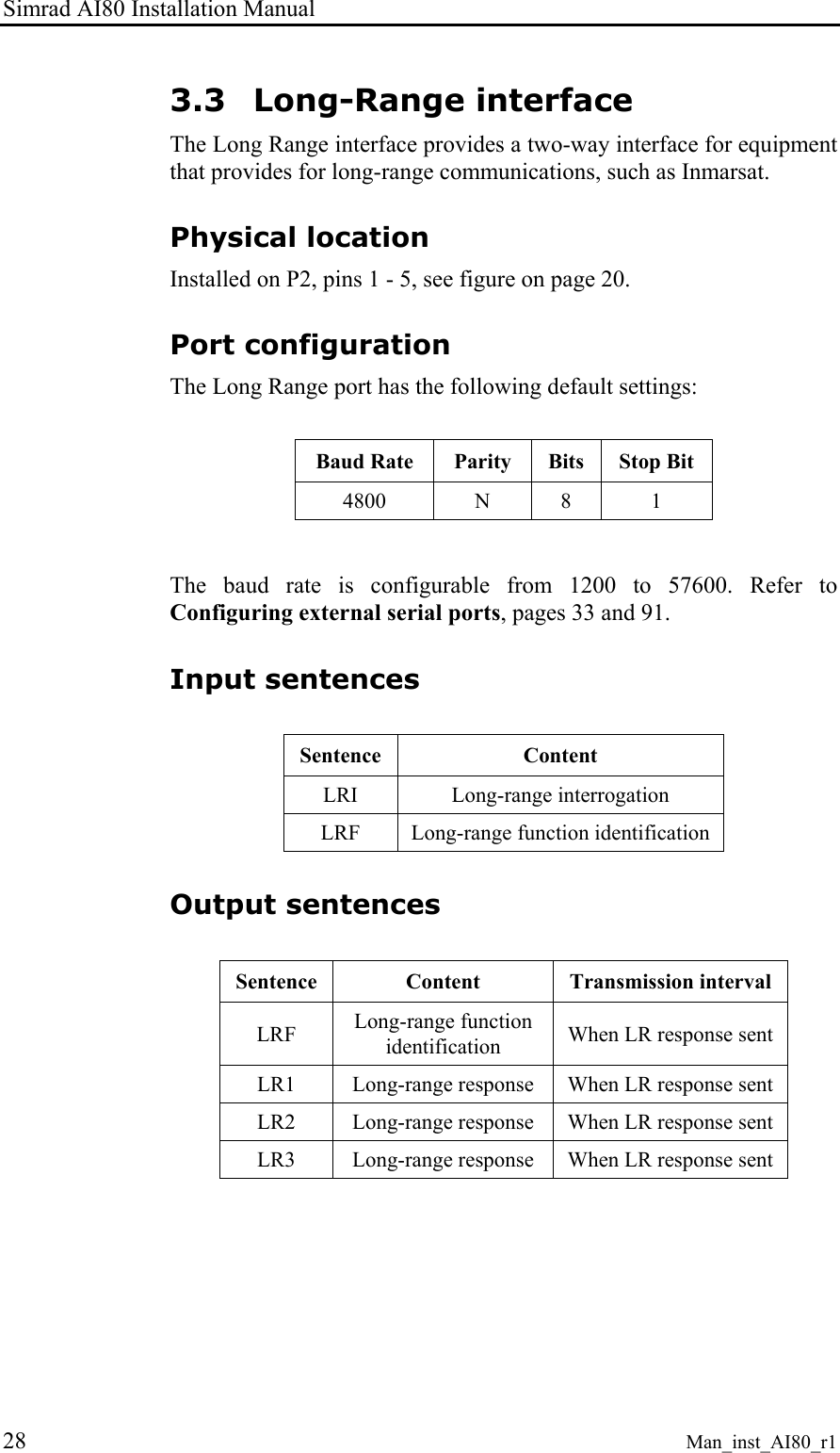
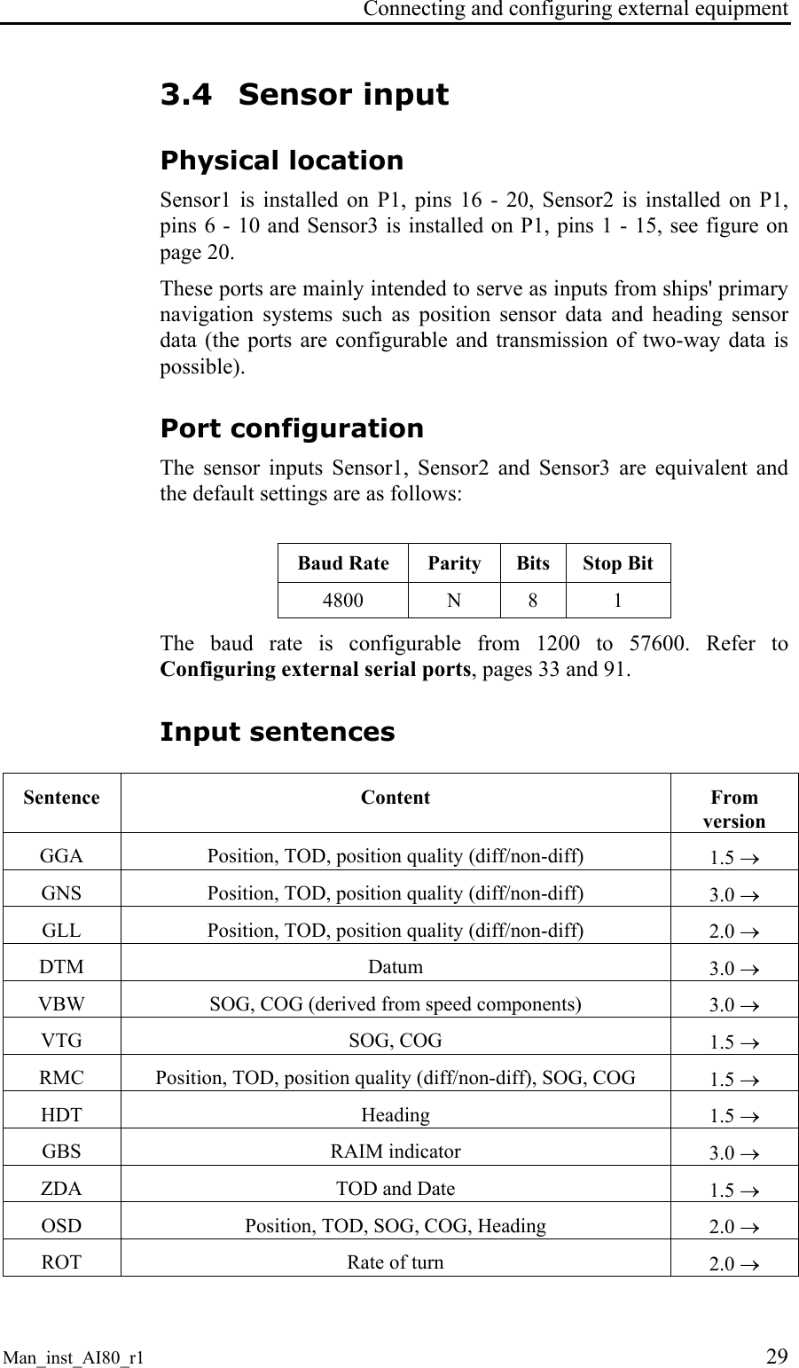
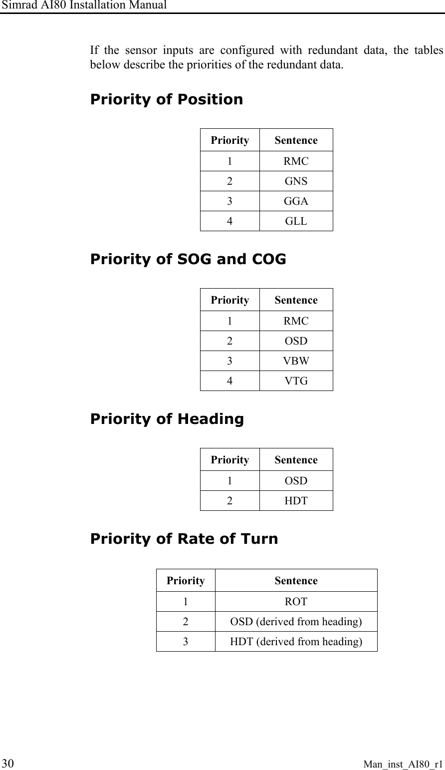
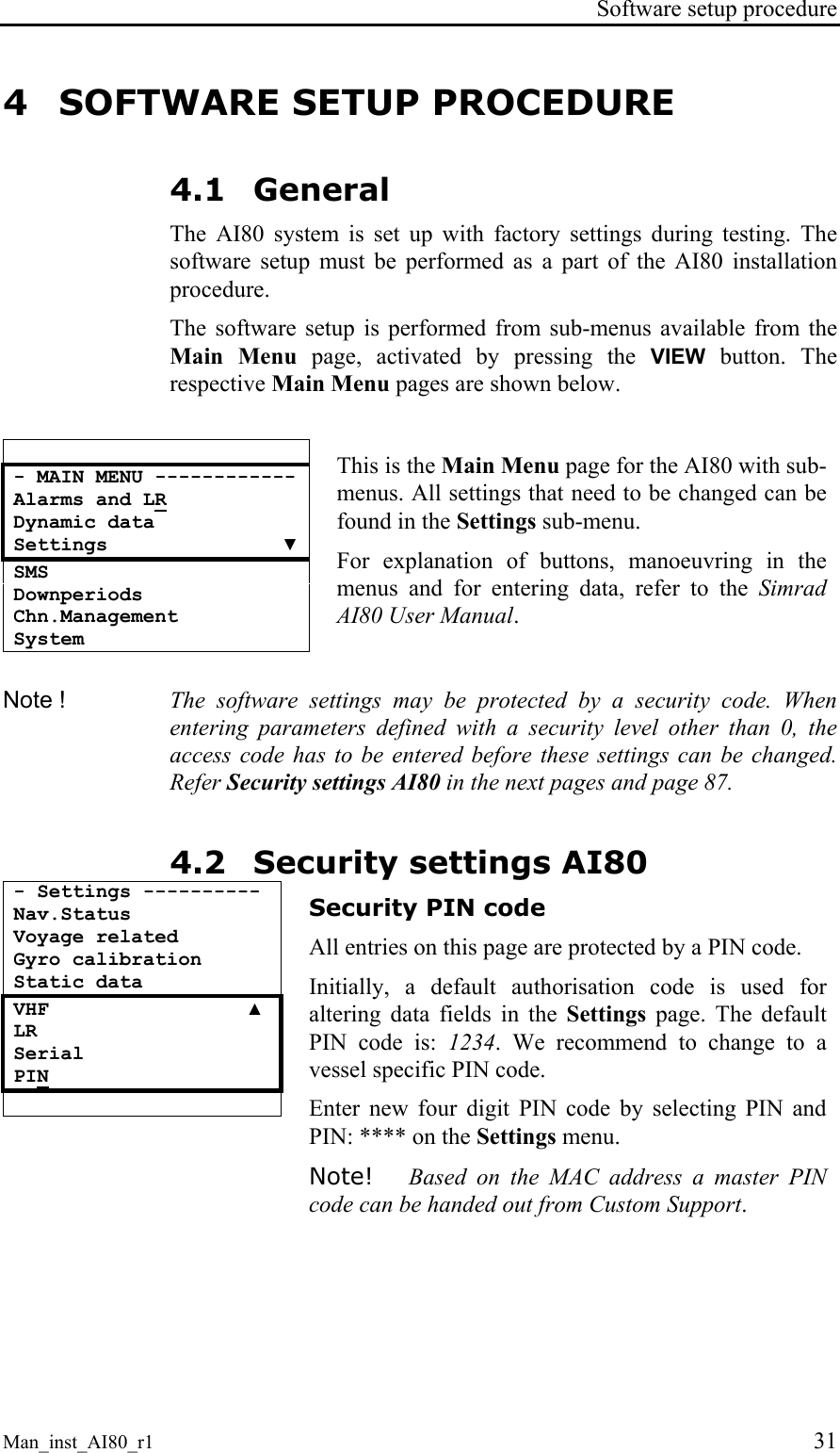
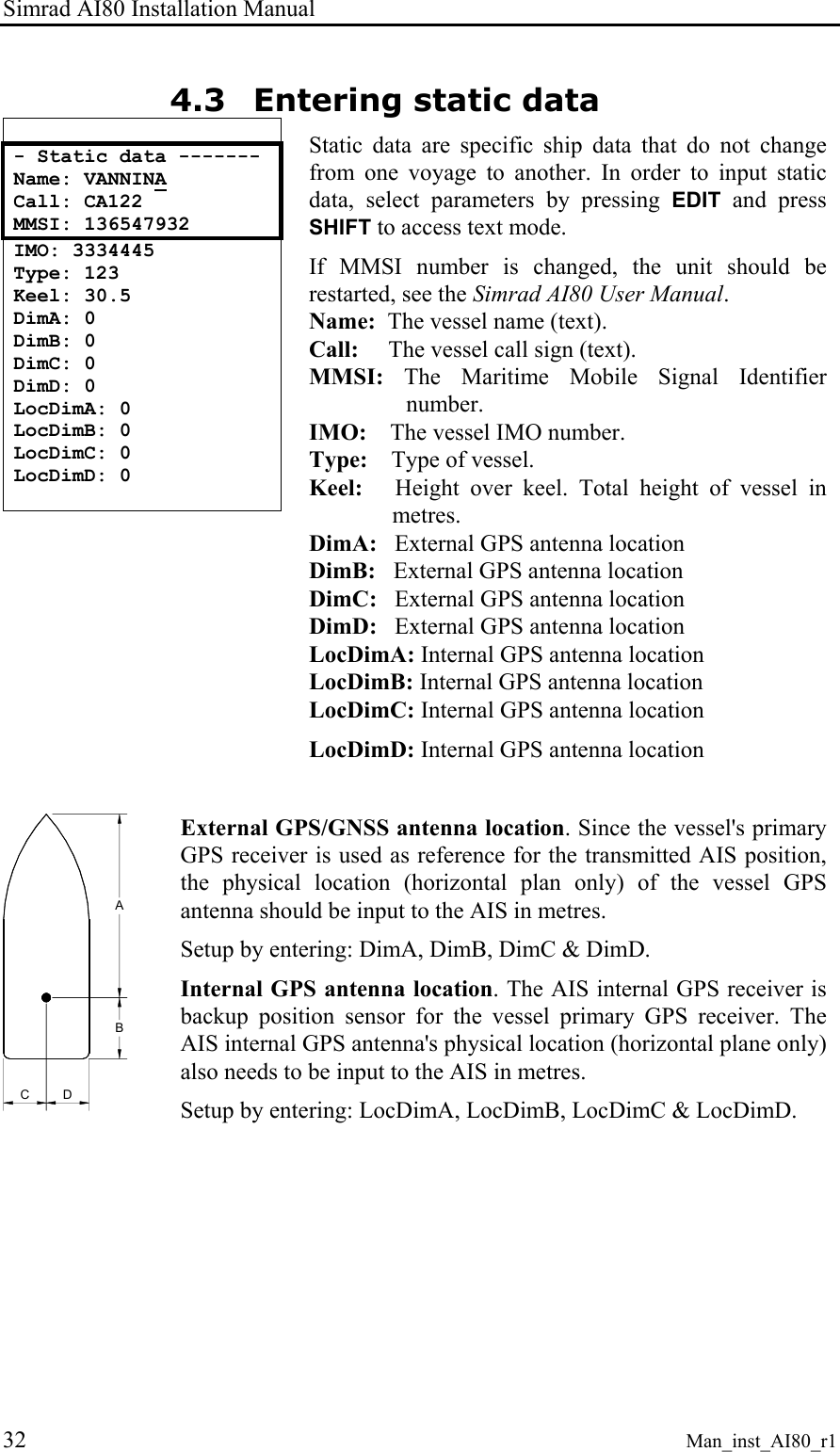
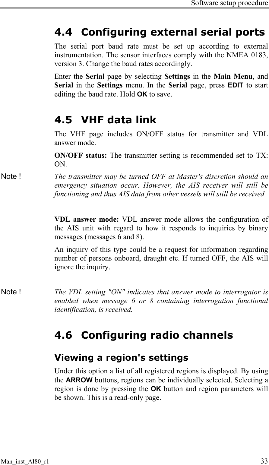
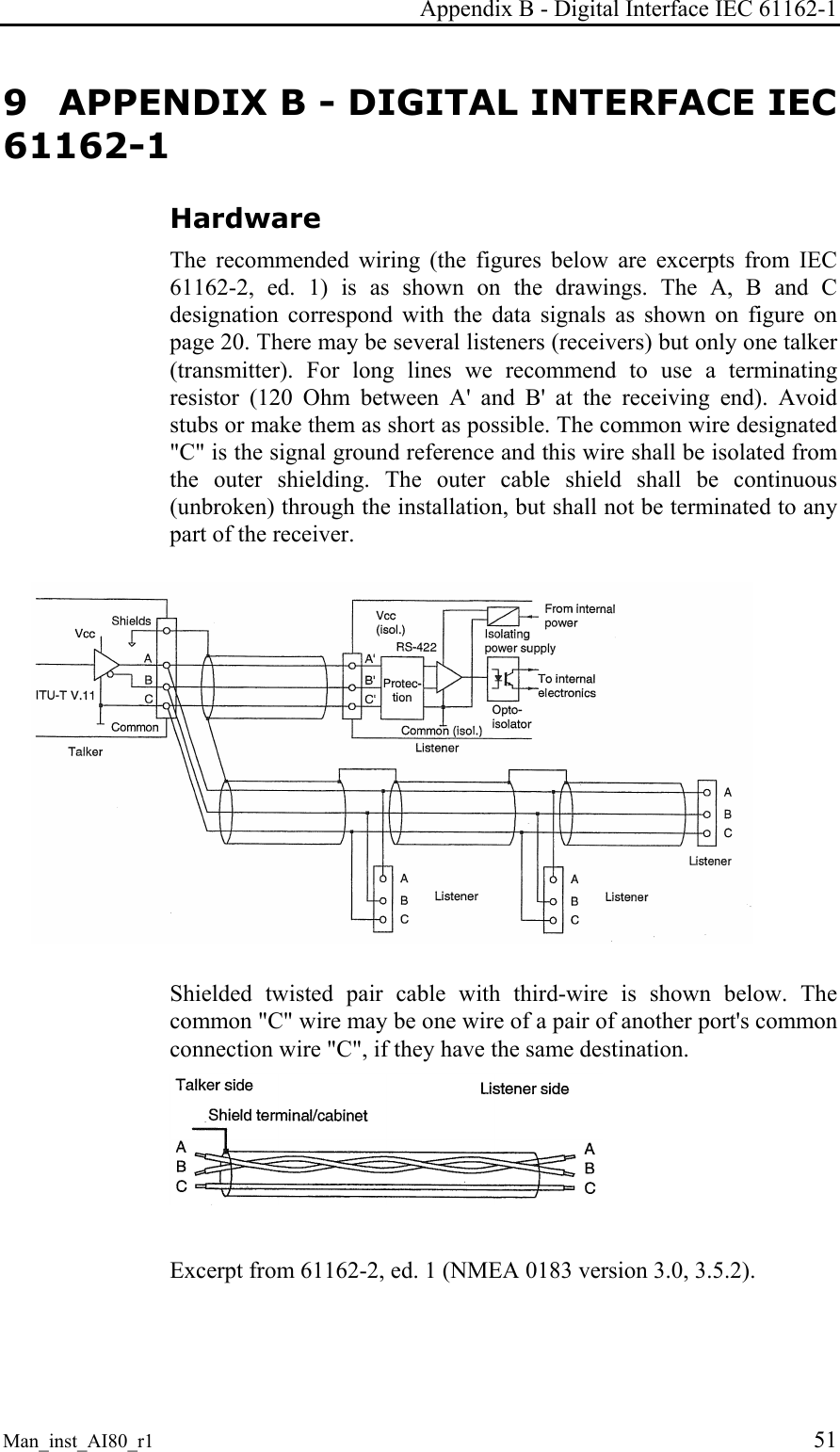
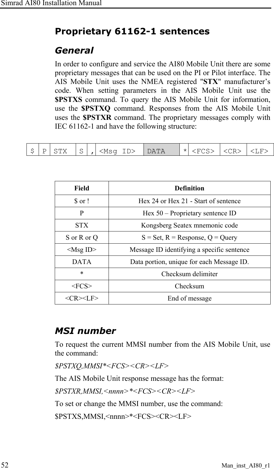
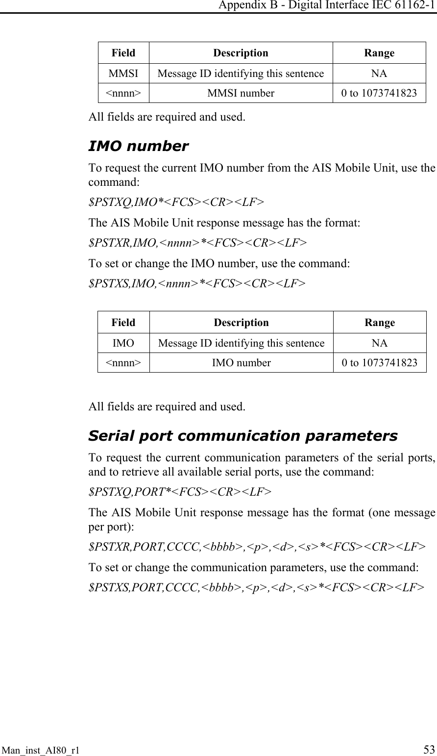
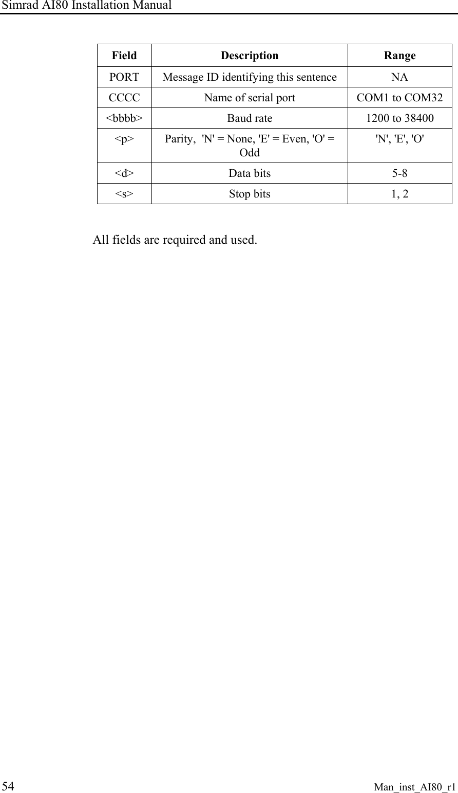
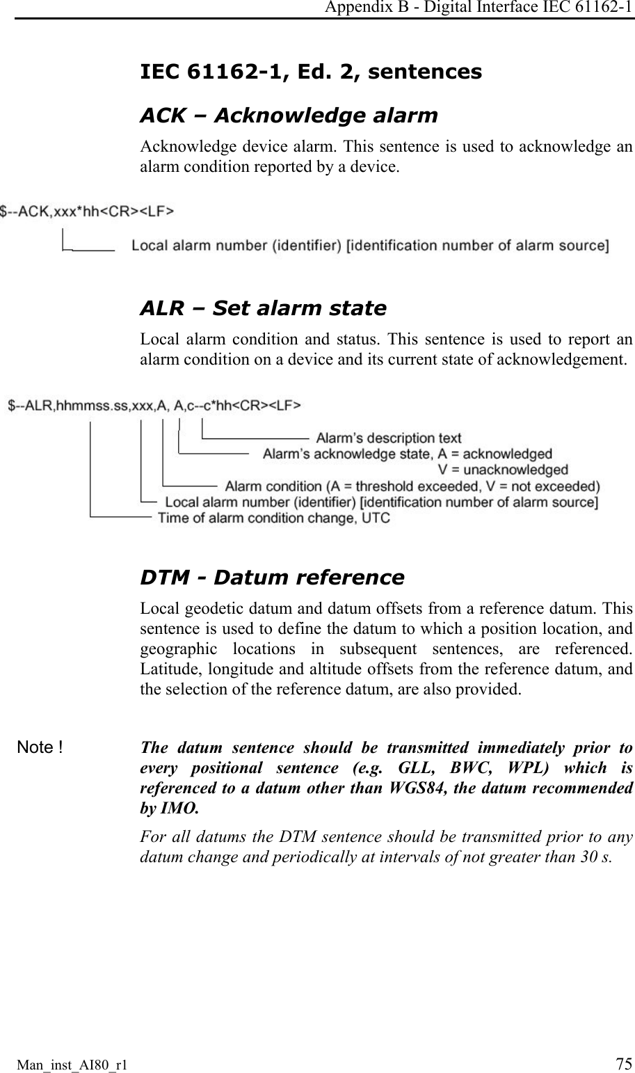
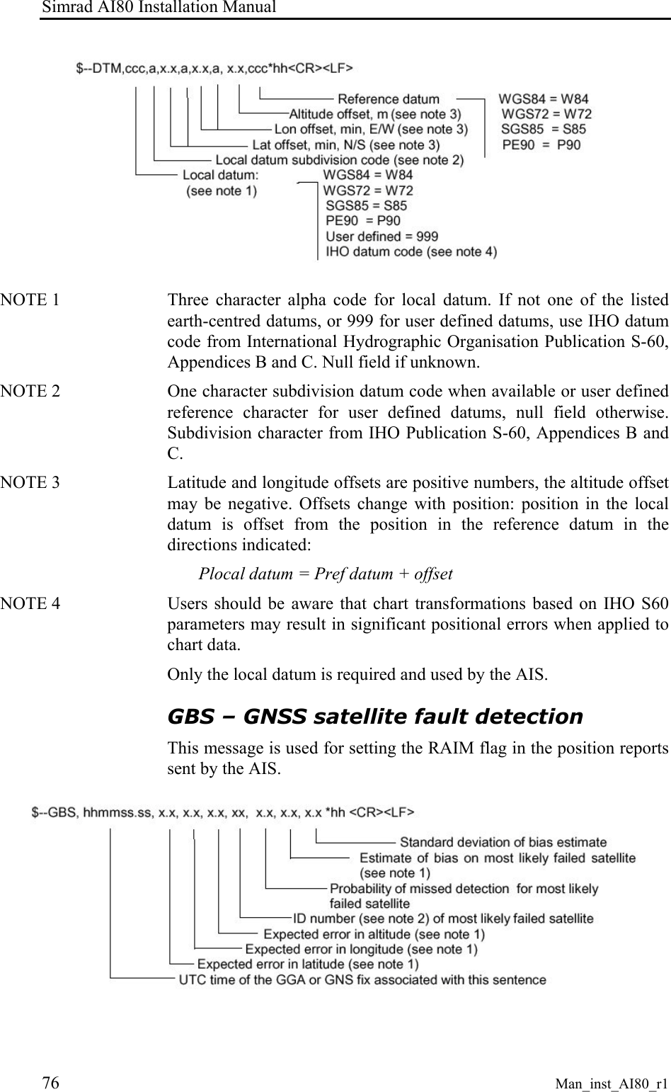
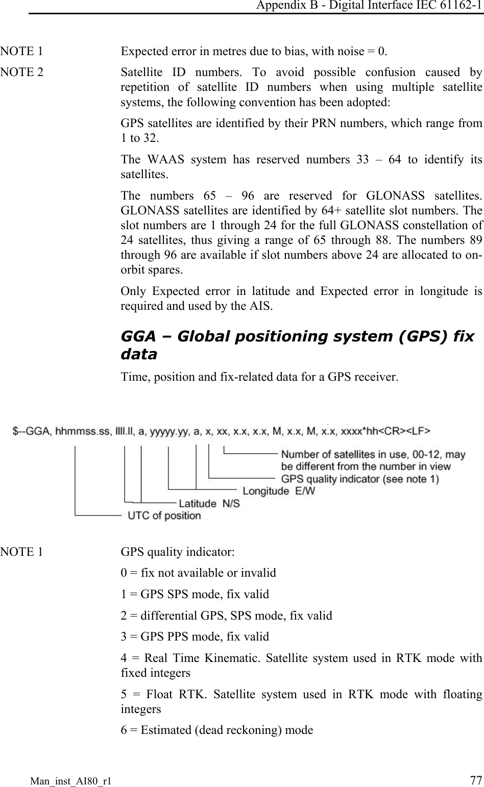
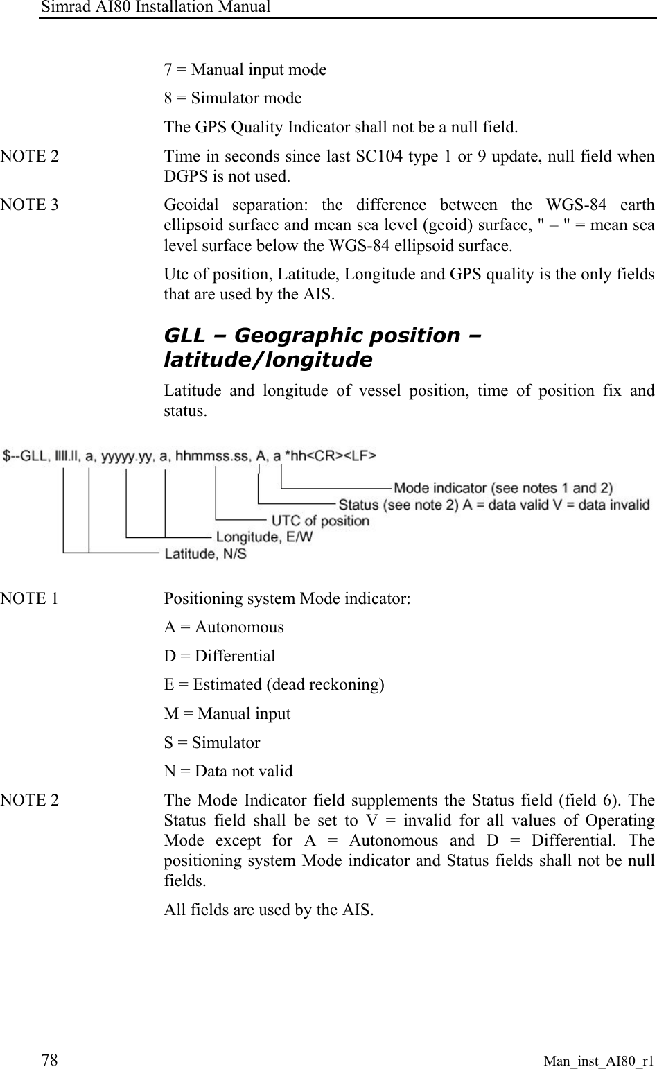
Installation manual Man_inst_AI80_r1 i  Installation Manual AI80 Automatic Identification System  This manual is intended as a reference guide for installing and maintaining the Simrad AI80 Automatic Identification System.
Simrad AI80 Installation Manual ii  Man_inst_AI80_r1 Document revisions Rev  Date  Written by  Checked by  Approved by 0 17.09.04  ISt  KKr  KKr 1 17.11.04  ISt  KKr  KKr                Document history Rev. 0  First edition. Rev. 1  FCC statements included.  To assist us in making improvements to this manual, we would welcome comments and constructive criticism. Please send all such - in writing to:  Kongsberg Seatex AS Pirsenteret N-7462 Trondheim, Norway  or by e-mail to: firmapost@kongsberg-seatex.no
Installation manual Man_inst_AI80_r1 iii About this manual This manual is intended as a reference guide for installing and maintaining the Simrad AI80 Automatic Identification System. In this manual, references to buttons on the control unit are written in boldface, and in a different text style (e.g. VIEW button, SHIFT button, ENTER button).  Important text that requires special attention from the reader is emphasized as follows:  Note!  Used to draw the reader’s attention to a comment or some important information.  Caution!  Used to warn the reader that a risk of damage to the equipment exists if care is not exercised.  WARNING!  Used when it is necessary to warn personnel that a risk of injury or death exists if care is not exercised.   FCC part 15 statement This equipment has been tested and found to comply with the limits for a Class A digital device, pursuant to Part 15 of the FCC Rules.  These limits are designed to provide reasonable protection against harmful interference when the equipment is operated in a marine and/or commercial environment. This equipment generates, uses and can radiate radio frequency energy and, if not installed and used in accordance with the instruction manual, may cause harmful interference to radio communications. The equipment is not inteded for operation in a residential area. Operation in such an area is likely to cause harmful interference in which case the user will be required to correct the interference at his own expense.  Additional information to the user Changes or modifications not expressly approved by Kongsberg Seatex AS will void the user's authority to operate the equipment.
Simrad AI80 Installation Manual iv  Man_inst_AI80_r1 This manual is divided in the following sections: 1. Technical specifications Specifications for the system and for all separate units in the AI80 system.. 2. Installation Reference guide for correct installation of the AI80 system. 3. Connecting and configuring external equipment Describes how external equipment is connected to the AI80 system. 4. Software setup procedure Reference guide for correct configuration of the AI80 system. 5. Maintenance Reference guide for correct configuration of the AI80 system. 6. Troubleshooting Troubleshooting procedures that could be performed for checking hardware and external interface. 7. Spare parts list Part numbers for all standard and optional units that may be included in the AI80 system. 8. Appendix A Vessel identifiers. 9. Appendix B IEC 61162-1, IEC/PAS 6162-100 sentence description. 10. Appendix C Software setup procedure using external, optional MKD. 11. Appendix D AIS troubleshooting form. 12. Appendix E Optional VHF antenna.
Installation manual Man_inst_AI80_r1 v Abbreviations and acronyms ABK  Addressed and Binary Broadcast Acknowledgement ABM  Addressed Binary and Safety Related Message ACA  AIS Regional Channel Assignment AIS  Universal Ship-borne Automatic Identification System AIS 1  161.975 MHz (87B – 2087) AIS 2  162.025 MHz (88B – 2088) ALR  Alarm ARPA  Automatic Radar Plotting Aid ASCII  American Standard Code for Information Interchange ATN  Aids to Navigation BIIT  Built In Integrity Tests COG  Course Over Ground DGPS  Differential GPS DGNSS  Differential Global Navigation Satellite System DSC  Digital Selective Calling ECDIS  Electronic Chart Display and Information System ECS  Electronic Chart System EMC  Electromagnetic Compatibility ETA  Estimated Time of Arrival FATDMA  Fixed Allocation TDMA GNSS  Global Navigation Satellite System GPS  Global Positioning System IALA  International Association of Lighthouse Authorities IEC  International Electrotechnical Commission IMO  International Maritime Organisation LR  Long Range MKD  Minimum Keyboard Display MMSI  Maritime Mobile Service Identity MSG  Message N/A  Not Applicable NMEA  National Marine Electronics Association
Simrad AI80 Installation Manual vi  Man_inst_AI80_r1 PI  Presentation Interface PPS  Pulse-per-second PUR  Polyurethane PWR  Power ROT  Rate of Turn RTCM  Radio Technical Commission of Maritime Service RX  Receive SAR  Search and Rescue SMS  Short Message Service SOG  Speed Over Ground SOTDMA  Self Organising TDMA TBD  To Be Defined TDMA  Time Division Multiple Access TX  Transmit TXT  Text Message UTC  Universal Co-ordinated Time VDL  VHF Data Link VDM  VHF Data Link Message VDO  VHF Data Link Own Vessel Message VHF  Very High Frequency
Installation manual Man_inst_AI80_r1 vii Contents 1 TECHNICAL SPECIFICATIONS.......................................................................1 1.1  Health, environment and safety ......................................................................1 1.2  Restrictions in guarantee ................................................................................1 1.3 Power ..............................................................................................................1 1.4 Data input .......................................................................................................1 1.5 Specifications..................................................................................................2 AI80 Mobile Unit ...........................................................................................2 AI80 Minimum Keyboard Display (MKD)....................................................5 GPS antenna (GPS4) ......................................................................................7 Pilot plug.........................................................................................................8 Optional, external MKD Unit.........................................................................8 2 INSTALLATION .................................................................................................11 2.1 General..........................................................................................................11 2.2  Unpacking and handling...............................................................................11 2.3 Installation procedure ...................................................................................11 2.4 Cabling..........................................................................................................13 2.5  Location of the units .....................................................................................15 Antenna location...........................................................................................15 2.6 MKD unit......................................................................................................16 Mechanical installation.................................................................................16 2.7  Optional MKD unit.......................................................................................17 Mechanical installation.................................................................................17 The optional MKD cable ..............................................................................18 2.8  AI80 Mobile Unit .........................................................................................19 Mechanical installation.................................................................................19 Cable connection ..........................................................................................19 Rear connections...........................................................................................19 Data signals...................................................................................................20 2.9 Pilot plug.......................................................................................................20 2.10 External alarm...............................................................................................21
Simrad AI80 Installation Manual viii  Man_inst_AI80_r1 2.11 GPS antenna .................................................................................................22 Mechanical installation.................................................................................22 GPS antenna offset arms...............................................................................22 Checking the antenna cable ..........................................................................23 Sealing antenna connectors ..........................................................................23 2.12 VHF antenna.................................................................................................23 3 CONNECTING AND CONFIGURING EXTERNAL EQUIPMENT ...........25 3.1 General..........................................................................................................25 3.2 Presentation interface ...................................................................................26 Physical location...........................................................................................26 Port configuration .........................................................................................26 Input sentences .............................................................................................26 Proprietary input sentences...........................................................................27 Output sentences...........................................................................................27 3.3 Long-Range interface ...................................................................................28 Physical location...........................................................................................28 Port configuration .........................................................................................28 Input sentences .............................................................................................28 Output sentences...........................................................................................28 3.4 Sensor input ..................................................................................................29 Physical location...........................................................................................29 Port configuration .........................................................................................29 Input sentences .............................................................................................29 Priority of Position........................................................................................30 Priority of SOG and COG.............................................................................30 Priority of Heading .......................................................................................30 Priority of Rate of Turn ................................................................................30 4 SOFTWARE SETUP PROCEDURE.................................................................31 4.1 General..........................................................................................................31 4.2  Security settings AI80 ..................................................................................31 4.3  Entering static data .......................................................................................32 4.4  Configuring external serial ports ..................................................................33
Installation manual Man_inst_AI80_r1 ix 4.5  VHF data link ...............................................................................................33 4.6  Configuring radio channels ..........................................................................33 Viewing a region's settings...........................................................................33 Adding a region ............................................................................................34 Edit current region ........................................................................................35 5 MAINTENANCE .................................................................................................37 5.1 General..........................................................................................................37 5.2 Periodic maintenance....................................................................................37 MKD Units ...................................................................................................37 Mobile Unit...................................................................................................37 5.3  Repair and modifications..............................................................................38 Exchanging antenna cables...........................................................................38 Exchanging GPS or VHF antennas ..............................................................38 5.4 Software updates...........................................................................................39 6 TROUBLESHOOTING ......................................................................................41 6.1 General..........................................................................................................41 6.2 Hardware problems.......................................................................................41 Power supply failure.....................................................................................42 GPS and VHF antenna cable connections ....................................................42 GPS and VHF antenna malfunction .............................................................42 GPS receiver failure......................................................................................42 VHF transceiver failure ................................................................................43 6.3  External data interface problems ..................................................................43 Data input from main GPS/GNSS source.....................................................43 Heading from vessel heading sensor ............................................................44 AIS unit restarts ............................................................................................44 7 SPARE PART LIST.............................................................................................45 7.1 Simrad AI80..................................................................................................45 8 APPENDIX A - VESSEL IDENTIFIERS..........................................................47 9 APPENDIX B - DIGITAL INTERFACE IEC 61162-1....................................51 Hardware ......................................................................................................51
Simrad AI80 Installation Manual x  Man_inst_AI80_r1 Proprietary 61162-1 sentences......................................................................52 New IEC 61162-1 sentences.........................................................................55 IEC 61162-1, Ed. 2, sentences......................................................................75 10 APPENDIX C - SOFTWARE SETUP USING OPTIONAL MKD ................87 10.1  Security settings optional MKD ...................................................................87 Setting the security codes .............................................................................87 Changing the security levels.........................................................................88 10.2  Entering static data optional MKD...............................................................90 10.3  Configuration external serial ports optional MKD.......................................91 10.4  Port settings and MAC address optional MKD............................................92 10.5  Answer mode optional MKD........................................................................93 10.6  Configuring radio channels optional MKD ..................................................94 Adding a region ............................................................................................95 Editing current region...................................................................................96 Viewing a region’s settings ..........................................................................96 11 APPENDIX D - TROUBLESHOOTING FORM .............................................97 12 APPENDIX E - OPTIONAL VHF ANTENNA.................................................99
Technical specifications Man_inst_AI80_r1 1 1 TECHNICAL SPECIFICATIONS 1.1 Health, environment and safety Operation or troubleshooting of Simrad AI80 equipment will not imply any risk for high voltages, explosions or exposure to gas. The AI80 is compliant with IEC 60950/EN60950 standards regarding product safety (low voltage) and IEC 60945/EN60945 standards on electromagnetic compatibility (immunity/radiation), vibration and climatic conditions. 1.2 Restrictions in guarantee The liability of the manufacturer is limited to repair of the AI80 only, and excludes consequential damages such as customer's loss of profit or damage to other systems traceable back to AI80 malfunction. The warranty does not cover malfunctions of the AI80 resulting from the following conditions: a)  The customer has opened the Mobile Unit b)  Over-voltage or incorrect power connection 1.3 Power Voltage input:................................24 V DC (nominal) range 18 – 35 V Power consumption:....................50 W peak, approx. 30 W continuous 1.4 Data input Gyro compass:................................................. NMEA 0183 version 3.0 GPS Main source: ........................................... NMEA 0183 version 3.0 DGPS corrections:......................................RTCM – SC104 version 2.1
Simrad AI80 Installation Manual 2 Man_inst_AI80_r1 1.5 Specifications AI80 Mobile Unit Dimensions:........................................................................ Refer page 3 Weight:..........................................................................................3.4 kg Colour:........................................................................................... Black Enclosure material:...............................................Varnished aluminium Environmental protection:............................................................... IP40 Temperature range: Operating:................................... –15 to +55°C (+5° to +131°F) Storage: ..................................... –25 to +60°C (-13° to +140°F) Humidity - operating:............................................................ 0-95% RH Vibration test: Displacement:..................................   1 mm from 2 Hz to 13 Hz Acceleration: ............................... 7 m/s2 from 13 Hz to 100 Hz Compass safe distance..................................................................0.35 m VHF radio: Number of transmitters: ............................................................1 Number of receivers:.................................................................3 Channel spacing: .................................................12.5 or 25 kHz Frequency range:................................................ 156 - 165 MHz Transmitter power: ............ 2 W or 12.5 W nominal (selectable) AIS 1 (Channel 87B):........................................... 161.975 MHz AIS 2 (Channel 88B):........................................... 162.025 MHz DSC receiver: ....................................................... 156.525 MHz GPS receiver: Type: ......................................................................Ashtech A12 Operating frequency (reception only): .................................. 1575.42 MHz ± 10 MHz
Technical specifications Man_inst_AI80_r1 3  TOP VIEW   TX MSG GPS ALM FRONT VIEW  REAR VIEW  SIDE VIEW EXPLODED
Simrad AI80 Installation Manual 4 Man_inst_AI80_r1   BOTTOM VIEW - EXPLODED  ISO VIEW
Technical specifications Man_inst_AI80_r1 5 AI80 Minimum Keyboard Display (MKD) Dimensions:............................................................................ See below Weight:..........................................................................................0.4 kg Colour:........................................................................................... Black Cable length (to Mobile Unit):..........................................................7 m Enclosure material:.......................................................................Plastic Environmental protection:..........................IP56 (when panel-mounted) Temperature range: Operating:.....................................–15 to +55°C (+5 to +131°F) Storage: ...................................... –25 to +70°C (–13 to +158°F) Humidity - operating:............................................................ 0-95% RH  OKCANCEL1 2 ABC 3DEF4GHI 5JKL 6MNO7PQRS 8TUV 9WXYZVIEW 0OFFDELEDITINFOSHIFTAISSIMRAD217 mm109 mm FRONT VIEW PilotplugMainunit96 mm206 mm REAR VIEW
Simrad AI80 Installation Manual 6 Man_inst_AI80_r1  50 mm SIDE VIEW  20120696951212Ш2.5 DRILLING & CUTOUT DIMENSION OF AI80 DISPLAY (MM)  A full-scale drawing of the display is supplied with the documentation package.
Technical specifications Man_inst_AI80_r1 7 GPS antenna (GPS4) Dimensions:.............................................................. Refer figure below Weight:......................................................................................0.130 kg Cable adapter set (2 cables): ....................................................2 x 0.5 m Voltage input:.................................5 V DC from the AI80 Mobile Unit Temperature range: ............................... -35°C - +70°C (-31° - +158°F) Humidity: .........................................................................100% (sealed) Mounting:..................................................... 1”14 thread (standard US) 2113131203834193
Simrad AI80 Installation Manual 8 Man_inst_AI80_r1 Pilot plug AMP CPC series 2/Receptable (Square Flanged) Shell size 11, 9-pin. The pilot plug is located at the rear of the MKD.  Optional, external MKD Unit Dimensions:............................................................................ See below Weight:.......................................................................... 0.9 kg (2.0 lbs.) Colour:........................................................................................... Black Cable length (to Mobile Unit):..........................................................7 m Enclosed material:.......................................... Epoxy coated aluminium Environmental protection:..........................IP56 (when panel-mounted) Temperature range - operating: ............. –25 to +55°C (–13 to +131°F) Temperature range - storage: ................. –30 to +80°C (–22 to +176°F)    FRONT VIEW
Technical specifications Man_inst_AI80_r1 9    VERTICALLY MOUNTED  HORISONTALLY MOUNTED
Simrad AI80 Installation Manual 10 Man_inst_AI80_r1    THIS PAGE INTENTIALLY LEFT BLANK
Installation Man_inst_AI80_r1 11 2 INSTALLATION 2.1 General To reduce the installation cost, crew members (Crew) qualified to perform electrical installations can perform part of the installation. However, qualified service personnel (SP) should carry out the final commissioning. 2.2 Unpacking and handling Care should be taken when unpacking and handling the equipment. A visual inspection should be made to ensure that the equipment has not been damaged during shipment, and that all parts are present.  A standard AI80 delivery includes: • AI80 Mobile Unit • AI80 MKD • GPS4 GPS antenna including mounting kit and cable adapter set • Documentation, including User and Installation manual 2.3 Installation procedure The table on the following pages describes a recommended installation procedure. It also describes items that could be performed by the vessel crew and items that must be carried out by qualified personnel. The table also includes page references to the various items' installation description in this manual.
Simrad AI80 Installation Manual  12 Man_inst_AI80_r1 Performed by Description Crew SP Ref page 1. Mount the GPS4 antenna included in the AI80 system and the third party VHF antenna.  x    2. Connect the adapter cable to the GPS4 antenna.  x     3. Pull cables from the antennas to the AI80 Mobile Unit.  x     4. Check the GPS and VHF cables for short circuit between the centre conductors and shield (ground).  x  23 5. Mount the AI80 Mobile Unit -  mount the MKD.  x  16 onwards 6. Connect the GPS adapter cable to antenna cable.  x     7. Connect the GPS4 antenna and the VHF antenna to the plugs on the rear of the Mobile Unit (connectors to be mounted by SP).  x  19 8. Connect the MKD unit to the Mobile Unit using the supplied cables.  x  19      9. Connect the external main GPS sensor to Sensor port 1, 2 or 3 on the Mobile Unit.   x   10. Connect the vessel’s main heading sensor to Sensor port 1, 2 or 3 on the Mobile Unit.   x   11. Provide other interface from external sensors to the Mobile Unit.    x   12. Connect the Power to the Mobile Unit. Make sure the power supply is from the vessel's emergency supply.   x   13. Apply power to the AI80 system.    x   14. Check that the indication on the LED indicators on the Mobile Unit is as follows: GPS LED:  blinks green once each second TX LED:  blinks green and amber, at the most 10 seconds between each blink MSG LED:  blinks green and amber, at the most 10 seconds between each blink   x  15. Perform the software setup procedure.    x
Installation Man_inst_AI80_r1 13 2.4 Cabling Double shielded coaxial cables equal or better than RG-214 are recommended when connecting the GPS and VHF antennas to the AI80 system. Coaxial cables should be installed in separate signal cable channels/tubes and at least 10 cm away from power supply cables. All outdoor installed connectors on the coaxial cables should be fitted with preventive isolation such as shrink-stocking with silicone to protect against water penetration. Avoid sharp bends of the cables. A bend may change the characteristic impedance of the cable.  CABLE NO.  DESCRIPTION  CABLE LENGTH  PART NO. 1  Interface cable to MKD/Pilot Plug  7 m  A101-13_1 2  Adapter cable GPS  0.5 m  A100-93 3  Interconnection cable GPS4  0.5 m  A101-03 4  Mounting kit, GPS antenna    A101-02 The figure below shows cables and cable length in a standard AI80 system. 1243 Note !  Shaded items and cables are not part of a standard AI80 scope of supply.
Simrad AI80 Installation Manual  14 Man_inst_AI80_r1 Antenna cables The antenna cables should be as short as possible to minimise attenuation of the signal. The cables should be located at least  10 cm away from power supply cables. The table below shows the maximum cable length (VHF) for the different antenna cable types.  Cable type  Max. length at 160 MHz RG58 10 metres “PUR” 58 * 10 metres RG213 30 metres RG214 * 30 metres LowLoss ½” * 100 metres * Recommended cable types.  Power cables Use minimum 2 x 2.5 mm2 cables to avoid voltage drop.
Installation Man_inst_AI80_r1 15 2.5 Location of the units The units included in the AI80 system should be mounted with special regard to the units’ environmental protection, temperature range and cable length. Refer Technical specifications, page 1 onwards. Antenna location The AIS equipment, like any other ship borne transceiver operating in the VHF maritime band, may cause interference to a ship’s VHF radiotelephone. This interference may occur as a periodic (e.g. every 20 s) soft clicking sound on a ship’s radiotelephone.  This affect may become more noticeable when the VHF radiotelephone antenna is located near the AIS VHF antenna, and when the radiotelephone is operating on channels near the AIS operating channels (e.g. channels 27, 28 and 86). The figure below shows recommended location and distance between the different antennas.
Simrad AI80 Installation Manual  16 Man_inst_AI80_r1 2.6 MKD unit Mechanical installation The MKD may be panel or bracket (option) mounted. The optional mounting bracket may be ordered separately. The unit should be mounted with special regard to the operator’s need for easy operation. Avoid mounting the MKD where it is easily exposed to sunlight, as this will shorten the lifetime of the display. If this is not possible, make sure the units are always covered with a protective cover when not in use. Panel mounting Make sure that the mounting location includes space for plug and cable bend. The mounting surface must be flat and even to within 0.5 mm. 1. Remove the 4 front panel corners from the MKD. 2. Drill 4 mounting holes and make a panel cut-out according to dimensional drawing, pages 5 and 6. 3. Fasten the MKD to the panel with the supplied 19 mm screws. 4. Apply the front panel corners.  Note !  Do not over-tighten the mounting screws.  Bracket mounting (option) When the MKD is bracket mounted (item A100-85), it is not weatherproof from the back. When bracket-mounted, the exposed parts of the plugs should be protected against salt corrosion. 1. Locate the cradle on the mounting site and mark the 4 holes for the screws on the mounting surface. 2. Drill the 4 holes and screw the cradle to the mounting surface. 3. Use the supplied screws to fasten the MKD to the left and right brackets. 4. Apply the front panel corners. Use the two locking knobs to assemble the cradle with the left and right brackets and adjust the MKD for the best viewing angle.
Installation Man_inst_AI80_r1 17 2.7 Optional MKD unit Mechanical installation The optional MKD may be panel or bracket (option) mounted. The optional mounting bracket may be ordered separately. The unit should be mounted with special regard to the operator’s need for easy operation. Avoid mounting the MKD where it is easily exposed to sunlight, as this will shorten the lifetime of the display. If this is not possible, make sure the units are always covered with the protective cover when not in use.  Panel mounting Make sure that the mounting location includes space for plug and cable bend. The mounting surface must be flat and even to within 0.5 mm. Gasket 1. Remove the 4 front panel corners from the MKD. 2. Drill 4 mounting holes and make a panel cut-out according to dimensional drawing, page 8. 3. Use the supplied gasket between the panel and the unit. 4. Fasten the MKD to the panel with the supplied 19 mm screws. 5. Apply the front panel corners.  Note !  Do not over-tighten the mounting screws.  Bracket mounting (option) When the MKD is bracket mounted (item A100-85), it is not weatherproof from the back due to a breathing hole in the back cabinet. When bracket-mounted, the exposed parts of the plugs should be protected against salt corrosion.
Simrad AI80 Installation Manual  18 Man_inst_AI80_r1  1. Locate the cradle on the mounting site and mark the 4 holes for the screws on the mounting surface. 2. Drill the 4 holes and screw the cradle to the mounting surface. 3. Use the supplied screws to fasten the MKD to the left and right brackets. 4. Apply the front panel corners. 5. Use the two locking knobs to assemble the cradle with the left and right brackets and adjust the MKD for the best viewing angle. The optional MKD cable The optional MKD is connected to the AI80 Mobile Unit with a 7-metre cable included with the MKD. The connector may be connected to any of the two inputs on the rear side of the MKD. The table below gives the pin layout for the MKD connector and the 9-pin D-sub connector that is connected to the Mobile Unit.   Signal name  MKD connector  Wire colour  D-sub 9-pin (Mobile Unit) Bus- 1 Brown 2 Bus+ 2 White  7 V System -  4  Black  1 2415 FRONT VIEW  V System +  5  White  6  Note !  Short circuit on the MKD connector may cause permanent damage to the AI80 Mobile Unit.
Installation Man_inst_AI80_r1 19 2.8 AI80 Mobile Unit Mechanical installation The Mobile Unit should be mounted in a place with proper ventilation. The unit is mounted with four bolts, refer dimensional drawing on page 4. Ensure that there is enough space on the rear side of the unit for installation of plugs and cables. A minimum distance of 220 mm between the unit and the wall is required. Make sure that unit is properly secured to the deck/bulkhead. Clamps are recommended to secure power and data cables connected to the Mobile Unit. Cable connection The rear panel of the Mobile Unit contains connectors for GPS, VHF, external MKD, data signals and power (+24V DC). The connector types are as shown in the table below:   Type  Connected to:  9 pins D-Sub, male  MKD  TNC connector, Female  GPS antenna  N-connector, Female  VHF antenna  Screw terminals P1, P2  Data I/O  Screw terminals  Power Rear connections  GPS VHF+POWEREXT MKDMKD PILOTP1 P2
Simrad AI80 Installation Manual  20 Man_inst_AI80_r1 Data signals The figure below shows the location of the AI80 data signals on the P1 (left connector row), P2 (right connector row). Refer to chapter 3 for description of signals. For detailed electrical description, see Appendix B - Digital interface IEC 61162-1.  P2P1111PI_RD(B) SENS3 RD(B)PI_RD(A) SENS3 RD(A)PI_TD(B) SENS3 TD(B)PI_TD(A) SENS3 TD(A)PI_C SENS3 CSENS1_RD(B) SENS2_RD(B)SENS1_RD(A) SENS2_RD(A)SENS1_TD(B) SENS2_TD(B)SENS1_TD(A) SENS2_TD(A)SENS1_C SENS2_C1020NC ALM NORXA_AUDIO ALM_CRXB_AUDIO ALM_NCRXC_AUDIO ALM CNot used LR_CCOM2_RXD COM1_RXDCOM2_TXD COM1_TXDGND GNDNot used LR_RD(B)Not used LR_RD(A)Not used LR_TD(B)Not used LR_TD(A)113 2412  Note !  RD(A) is low relative to RD(B) when idle. TD(A) is low relative to TD(B) when idle. Note !  All data cables must be twisted pair cables with shield.  All cables should be terminated to shield using the clamps on the mounting plate. 2.9 Pilot plug   A Pilot plug is included in the AI80 system and is located at the rear of the AI80 MKD. The plug is used for connecting a Personal Pilot Unit (PPU) to the AI80 system.
Installation Man_inst_AI80_r1 21 The pilot plug is an AMP CPC series 2/Receptacle (Square Flanged), Shell size 11, 9-pin. In case of a panel mounted MKD, an extension cord must be used. Default baud rate is 38400, N, 8, 1.  Signal name Seatex notation  Pin on AMP 206486-1 TX(A) Pilot_TD(A) (TXA)  1 TX(B) Pilot_TD(B) (TXB)  4 RX(A) Pilot_RD(A) (RXA)  5 RX(B) Pilot_RD(B) (RXB)  6 Shield Shield  9 2.10 External alarm The Mobile Unit does not include an acoustic alarm, but has a built-in alarm functionality. An alarm will open the alarm relay, which can be used to trigger an external alarm. The diagram below shows how an external alarm may be connected to the rear of the Mobile Unit.  AI80RearPanel11   12P2+-+-BUZZERNC NO+-ALM_CALM_NCFROM UPS SUPPLY
Simrad AI80 Installation Manual  22 Man_inst_AI80_r1 2.11 GPS antenna Mechanical installation The GPS antenna included in the AI80 system is used for time synchronisation and computation of backup position fix. In addition to this GPS antenna, the AI80 should be connected to the vessel’s main GPS system at the rear of the Mobile Unit. Sensor input 1-3 may be used. Optimum location of the GPS antenna is important to ensure continuous track of all visible GPS satellites. The following should be taken into consideration during installation: • The GPS antenna must be installed where it has a clear view of the sky and thus the objective is to see the horizon freely through 360 degrees with a vertical observation of 5 to 90 degrees above the horizon. • Small diameter obstructions, such as masts and booms, do not seriously degrade signal reception but such objects must not eclipse more than a few degrees of any given bearing. • The antenna should be located at least 3 metres away from and out of the transmitting beam of high power transmitters (S-band radar and/or Inmarsat systems). This includes the ship's own AIS VHF antenna if it is located separately. Refer figure on page 15. Use the supplied antenna mounting kit when mounting the antenna. Appropriate crimping tools must be used. CDBA GPS antenna offset arms The mounting location for the internal GPS antenna and for the main GPS antenna connected to the AI80 system, needs to be input to the AI80 as a part of the configuration settings. The figure shows the offset arms that have to be configured. Refer Entering static data, pages 32 and 90.
Installation Man_inst_AI80_r1 23 Checking the antenna cable After the mechanical and electrical installation is completed, the coaxial cables should be checked for short circuit between centre conductor and shield (ground) with the antenna disconnected. If not short-circuited, the antenna cable could be connected to the Mobile Unit. Sealing antenna connectors The outdoor antenna connectors have to be sealed with self-bounding tape and PVC/Vinyl tape for waterproofing. Coil the self-bounding tape from one cable end to the other. Use at least two layers of tape. After coiling, make a bounding by pressure of fingers.  Coil at least two layers of PVC/Vinyl tape without stretching. After coiling, make a bounding by pressure of fingers.   2.12 VHF antenna The VHF antenna is not included in a standard AI80 system, but has to be part of the AIS installation. A qualified antenna must cover marine band (156 MHz - 164 MHz), have omni-directional vertical polarization and provide 2 to 5 dB gain. For installation of this antenna, refer to documentation delivered by the antenna supplier. Refer also to the figure on page 15 for location. Verify that there is no short circuit between centre conductors and shield (ground) before the cable is connected to the Mobile Unit. Seal the antenna connectors as described for the GPS antenna. As an option Kongsberg Seatex AS may provide an antenna with part number A100-58, shown in Appendix E - Optional VHF antenna.
Simrad AI80 Installation Manual  24 Man_inst_AI80_r1     THIS PAGE INTENTIALLY LEFT BLANK
Connecting and configuring external equipment Man_inst_AI80_r1 25 3 CONNECTING AND CONFIGURING EXTERNAL EQUIPMENT 3.1 General In general, all sensors installed in compliance with other carriage requirements of SOLAS Chapter V should be connected to the AI80 system. Increased navigational performance can be achieved by interfacing the AI80 to an ECDIS, ECS and/or radar.  All external equipment is connected to the AI80. For termination, refer Data signals, page 20. VHF-transmitterVHF-receive ch. 70VHF-receive ch. AIS 1VHF-receive ch. AIS 2GPS receiverInterface boardVHF switchAIS TransponderGNSS/DGNSSAntennaVHF Antenna HeadingGNSSRate of TurnECDISRadarMKD unit Note !  Shielded twisted pair cables shall be used for the high-speed serial data ports.  The following sections present the port configuration and IEC 61162-1 sentences that may be used when connecting external equipment to the AI80 system. Detailed description of the IEC 61162-1 sentences are found in Appendix B - Digital interface IEC 61162-1, page 51. For terminal location, refer to the figure on page 20.
Simrad AI80 Installation Manual 26 Man_inst_AI80_r1 3.2 Presentation interface The presentation interface consists of two physical ports: PI and Pilot port. Both ports are functionally equivalent. The  PI port provides a primary port for connecting onboard equipment such as ECDIS, radar, Long Range AIS etc. The Pilot port is used for the Pilot Plug included in the AI80 system. This plug is intended for the ship's pilot equipment, service equipment, etc. Physical location Installed on P1, pins 11 - 15. See figure on page 20. Port configuration The PI and Pilot port have the following default settings:  Baud Rate  Parity  Bits  Stop Bit 38400 N 8 1  The baud rate is configurable to either 38400 or 57600. This due to the amount of data. Refer to Configuring external serial ports, pages 33 and 91. Input sentences  Sentence  Content VSD  Voyage static data SSD  Ship static data ABM  Addressed binary message BBM  Broadcast binary message AIR  AIS interrogation message ACA  AIS channel assignment command ACK Acknowledgement message LRF  Long range acknowledge
Connecting and configuring external equipment Man_inst_AI80_r1 27 Proprietary input sentences  Sentence  Content MMSI MMSI number IMO IMO number PORT  Serial port configuration parameters Output sentences  Sentence  Content  Transmission interval ABK Acknowledgement message Upon reception of messages 7 and 13, and when sending message 15 VDO  VHF Data link own message  1 Hz nominal ALR  Alarm messages  30 seconds/1 min. TXT  Indication messages  When change of status ACA  AIS channel assignment command  When change of status VDM  VHF Data link message  When receiving on VDL LRI Long-range interrogation When LR request received & when LR response sent LRF  Long-range function identification When LR request received & when LR response sent LR1  Long-range response  When LR response sent LR2  Long-range response  When LR response sent LR3  Long-range response  When LR response sent
Simrad AI80 Installation Manual 28 Man_inst_AI80_r1 3.3 Long-Range interface The Long Range interface provides a two-way interface for equipment that provides for long-range communications, such as Inmarsat. Physical location Installed on P2, pins 1 - 5, see figure on page 20. Port configuration The Long Range port has the following default settings:  Baud Rate  Parity  Bits  Stop Bit 4800 N 8 1  The baud rate is configurable from 1200 to 57600. Refer to Configuring external serial ports, pages 33 and 91. Input sentences  Sentence  Content LRI Long-range interrogation LRF  Long-range function identification Output sentences  Sentence  Content  Transmission interval LRF  Long-range function identification  When LR response sent LR1  Long-range response  When LR response sent LR2  Long-range response  When LR response sent LR3  Long-range response  When LR response sent
Connecting and configuring external equipment Man_inst_AI80_r1 29 3.4 Sensor input Physical location Sensor1 is installed on P1, pins 16 - 20, Sensor2 is installed on P1, pins 6 - 10 and Sensor3 is installed on P1, pins 1 - 15, see figure on page 20. These ports are mainly intended to serve as inputs from ships' primary navigation systems such as position sensor data and heading sensor data (the ports are configurable and transmission of two-way data is possible). Port configuration The sensor inputs Sensor1, Sensor2 and Sensor3 are equivalent and the default settings are as follows:  Baud Rate  Parity  Bits  Stop Bit 4800 N 8 1 The baud rate is configurable from 1200 to 57600. Refer to Configuring external serial ports, pages 33 and 91. Input sentences    Sentence Content  From version GGA  Position, TOD, position quality (diff/non-diff)  1.5 → GNS  Position, TOD, position quality (diff/non-diff)  3.0 → GLL  Position, TOD, position quality (diff/non-diff)  2.0 → DTM Datum 3.0 → VBW  SOG, COG (derived from speed components)  3.0 → VTG SOG, COG 1.5 → RMC  Position, TOD, position quality (diff/non-diff), SOG, COG  1.5 → HDT Heading 1.5 → GBS RAIM indicator 3.0 → ZDA  TOD and Date  1.5 → OSD  Position, TOD, SOG, COG, Heading  2.0 → ROT  Rate of turn  2.0 →
Simrad AI80 Installation Manual 30 Man_inst_AI80_r1 If the sensor inputs are configured with redundant data, the tables below describe the priorities of the redundant data. Priority of Position  Priority  Sentence 1 RMC 2 GNS 3 GGA 4 GLL Priority of SOG and COG  Priority  Sentence 1 RMC 2 OSD 3 VBW 4 VTG Priority of Heading  Priority  Sentence 1 OSD 2 HDT Priority of Rate of Turn  Priority  Sentence 1 ROT 2  OSD (derived from heading) 3  HDT (derived from heading)
Software setup procedure  Man_inst_AI80_r1 31 4 SOFTWARE SETUP PROCEDURE 4.1 General The AI80 system is set up with factory settings during testing. The software setup must be performed as a part of the AI80 installation procedure. The software setup is performed from sub-menus available from the Main Menu page, activated by pressing the VIEW button. The respective Main Menu pages are shown below.    - MAIN MENU ------------ Alarms and LR Dynamic data Settings               ▼ SMS Downperiods Chn.Management System  This is the Main Menu page for the AI80 with sub-menus. All settings that need to be changed can be found in the Settings sub-menu. For explanation of buttons, manoeuvring in the menus and for entering data, refer to the Simrad AI80 User Manual. Note !  The software settings may be protected by a security code. When entering parameters defined with a security level other than 0, the access code has to be entered before these settings can be changed. Refer Security settings AI80 in the next pages and page 87. 4.2 Security settings AI80 - Settings ---------- Nav.Status Voyage related Gyro calibration  Static data VHF                 ▲ LR Serial PIN    Security PIN code All entries on this page are protected by a PIN code. Initially, a default authorisation code is used for altering data fields in the Settings page. The default PIN code is: 1234. We recommend to change to a vessel specific PIN code. Enter new four digit PIN code by selecting PIN and PIN: **** on the Settings menu. Note!   Based on the MAC address a master PIN code can be handed out from Custom Support.
Simrad AI80 Installation Manual 32 Man_inst_AI80_r1 4.3 Entering static data  - Static data ------- Name: VANNINA Call: CA122 MMSI: 136547932 IMO: 3334445 Type: 123 Keel: 30.5 DimA: 0 DimB: 0 DimC: 0 DimD: 0 LocDimA: 0 LocDimB: 0 LocDimC: 0 LocDimD: 0   Static data are specific ship data that do not change from one voyage to another. In order to input static data, select parameters by pressing EDIT and press SHIFT to access text mode. If MMSI number is changed, the unit should be restarted, see the Simrad AI80 User Manual. Name:  The vessel name (text). Call:     The vessel call sign (text). MMSI: The Maritime Mobile Signal Identifier number. IMO:    The vessel IMO number. Type:    Type of vessel. Keel:   Height over keel. Total height of vessel in metres. DimA:   External GPS antenna location DimB:   External GPS antenna location DimC:   External GPS antenna location DimD:   External GPS antenna location LocDimA: Internal GPS antenna location LocDimB: Internal GPS antenna location LocDimC: Internal GPS antenna location LocDimD: Internal GPS antenna location  CDBA External GPS/GNSS antenna location. Since the vessel's primary GPS receiver is used as reference for the transmitted AIS position, the physical location (horizontal plan only) of the vessel GPS antenna should be input to the AIS in metres. Setup by entering: DimA, DimB, DimC & DimD. Internal GPS antenna location. The AIS internal GPS receiver is backup position sensor for the vessel primary GPS receiver. The AIS internal GPS antenna's physical location (horizontal plane only) also needs to be input to the AIS in metres. Setup by entering: LocDimA, LocDimB, LocDimC & LocDimD.
Software setup procedure  Man_inst_AI80_r1 33 4.4 Configuring external serial ports The serial port baud rate must be set up according to external instrumentation. The sensor interfaces comply with the NMEA 0183, version 3. Change the baud rates accordingly. Enter the Serial page by selecting Settings in the Main Menu, and Serial in the Settings menu. In the Serial page, press EDIT  to start editing the baud rate. Hold OK to save. 4.5 VHF data link The VHF page includes ON/OFF status for transmitter and VDL answer mode. ON/OFF status: The transmitter setting is recommended set to TX: ON. Note !  The transmitter may be turned OFF at Master's discretion should an emergency situation occur. However, the AIS receiver will still be functioning and thus AIS data from other vessels will still be received.  VDL answer mode: VDL answer mode allows the configuration of the AIS unit with regard to how it responds to inquiries by binary messages (messages 6 and 8).  An inquiry of this type could be a request for information regarding number of persons onboard, draught etc. If turned OFF, the AIS will ignore the inquiry.  Note !  The VDL setting "ON" indicates that answer mode to interrogator is enabled when message 6 or 8 containing interrogation functional identification, is received. 4.6 Configuring radio channels Viewing a region's settings Under this option a list of all registered regions is displayed. By using the ARROW buttons, regions can be individually selected. Selecting a region is done by pressing the OK button and region parameters will be shown. This is a read-only page.
Simrad AI80 Installation Manual 34 Man_inst_AI80_r1 Adding a region  - Add region --------- ChnA: 0 ChnB: 0 RxTx: TxA/TxB, RxA/Rx▼ TxPower: LOW LAT NE:  00°00'00.00N LON NE: 000°00'00.00E LAT SW:  00°00'00.00N LON SW: 000°00'00.00E BW A: Default BW B: Default Zone: 0 Hold [OK] to save  To edit these parameters, use the ARROW keys to manoeuvre to the parameter of interest and press EDIT. Use the DEL button if necessary, and enter the new value. If non-digits are required, press the SHIFT button to change to alpha mode. Press the SHIFT button again to return to digit mode.  While in alpha mode, letters and special characters can be entered (e.g. the degree  symbol °).  Note !  If the user tries to enter a region which parameters locates the region more than 500 nautical miles away from the vessel, the region will automatically be discarded. Also when the vessel position is further than 500 nautical miles from the region, this region is automatically discarded by the AIS unit.  ChA: The radio channel to be used as channel A. ChB: The radio channel to be used as channel B. RxTx: Transmission/reception mode. This parameter indicates whether or not the AIS should transmit and receive on both channels, or on only a subset of these. TxPower: The transmission power of the radio. Low equals 2W, and High equals 12W. Lat/Lon: The rectangular area to which the radio parameters apply. The area is specified by entering the coordinates for the north-east corner and the south-west corner. BW A: Bandwidth for the selected channel A. BW B: Bandwidth for the selected channel B. Zone: Transition zone for the region. This parameter is given in nautical miles, and provides information about the transition zone of the region in which the AIS should change radio parameters to the ones specified for the region.
Software setup procedure  Man_inst_AI80_r1 35 Edit current region This function is used to change the current radio parameters and is similar to Add Region, the only difference being that by changing these values the default parameters for the current region are altered and take effect immediately.  Note !  For software setup procedure using optional MKD see Appendix C - Software setup using optional MKD on page 87.
Simrad AI80 Installation Manual 36 Man_inst_AI80_r1   THIS PAGE INTENTIALLY LEFT BLANK
Maintenance Man_inst_AI80_r1 37 5 MAINTENANCE 5.1 General All units in the AI80 system are “repair by replacement” units, and the operator is therefore required to perform only a limited amount of preventive maintenance on the units. The service in the field is limited to: • Replacing damaged GPS or VHF antenna cables • Replacing failed AI80 system units A damaged unit that has to be shipped back to the supplier, should be sent in the original transportation box or another appropriate box. The return address is provided in the first pages of this manual. 5.2 Periodic maintenance The AI80 system should regularly be checked for firm and fixed mounting of the chassis in order to avoid excessive resonances. All connectors should be checked for good mechanical and electrical connections. Cables should not be bent more than the minimum recommended bending radius and there should be no sharp bends on coaxial cables. All cables should be fixed tight and rigid to their supporting structure (bulkhead, mast etc.) and special care should be taken where cables run through holes with sharp edges. MKD Units The MKD will under normal use require little maintenance. If the unit requires any form of cleaning, use fresh water and a mild soap solution (not a detergent). It is important to avoid using chemical cleaners and hydrocarbons such as diesel, petrol etc.  Mobile Unit A properly operating Mobile Unit will indicate transmitting and receiving messages by short blinks on the TX and MSG LEDs. Inspecting the LEDs for normal operation gives a good indication of the operating status. Any red LED indication means that further investigation and servicing is necessary, see chapter 6.1.
Simrad AI80 Installation Manual 38 Man_inst_AI80_r1 5.3 Repair and modifications The units in the AI80 system are not designed for customer repair. All repairs and modifications of the units should be carried out by qualified personnel. A failed unit should be shipped back to the supplier for repair. Exchanging antenna cables 1. Disconnect the power cable. 2. Dismount the damaged antenna cable. The new antenna cable must be as straight as possible. Do not crush or crimp the cable, as this will affect the electrical properties of the cable. 3. Connect the antenna cable to the antenna. 4. Seale the connection between the antenna and the antenna cable against water penetration as described in page 23. 5. Connect the antenna cable to the AI80 Mobile Unit and reapply power.  Note !  If the GPS antenna cable is attached to the Mobile Unit, do not attach the antenna cable to the antenna when the AI80 is powered. If the antenna cable is short-circuited with power on, the GPS receiver within the unit can be damaged. Exchanging GPS or VHF antennas 1. Disconnect the power cable. 2. Dismount the failed antenna. 3. Mount the new antenna on the antenna rod.  4. Connect the antenna cable to the antenna. 5. Seale the connection between the antenna and the antenna cable against water penetration as described in page 23. 6. Connect the antenna cable to the AI80 Mobile Unit and reapply power.  Note !  If the GPS antenna cable is attached to the Mobile unit, do not attach the antenna cable to the antenna when the AI80 is powered. If the antenna cable is short-circuited with power on, the GPS receiver within the unit can be damaged.
Maintenance Man_inst_AI80_r1 39 5.4 Software updates The software in the AI80 system can be upgraded to the latest version in the field by changing the compact flash inside the Mobile Unit. Do the following: 1. Enter the System  menu, select Software upgrade and  Start upgrade. Follow on-screen instructions. Power off the unit. 2. Open the front panel. 3. Locate the compact flash and gently remove it. 4. Insert new compact flash and close front panel. 5. Power on the unit.
Simrad AI80 Installation Manual 40 Man_inst_AI80_r1    THIS PAGE INTENTIALLY LEFT BLANK
Troubleshooting Man_inst_AI80_r1 41 6 TROUBLESHOOTING 6.1 General The LED indicators on the front of the Mobile Unit can be used to monitor status as well as data reception and transmission.  LED Colour Description TX  Off Amber Green Red Transmitter idle Transmitting on AIS channel B Transmitting on AIS channel A Transmitter turned off MSG  Off Amber Green No message/report being received Message/report received on channel B Message/report received on channel A GPS  Amber Green Indirect synchronisation free run Internal GPS OK, GPS synch selected ALM  Off Red No alarm Alarm - alarm relay activated  Prior to any troubleshooting, the system should be restarted to see if this resolves the problem.  • Restart the Mobile Unit as described in the Simrad AI80 User Manual. • Remove the + 24 V power supply cable and then reapply power. 6.2 Hardware problems Hardware problems can be divided into the following categories: • Power supply failure • GPS receiver failure • VHF transceiver failure • GPS and VHF antennas and cables • Interface cables
Simrad AI80 Installation Manual 42 Man_inst_AI80_r1 If the system outputs an alarm, the alarm condition can be read from the display. Power supply failure If the unit periodically restarts approximately every one minute, this could indicate a power supply failure.  Use the following procedure to check for power failure: 1.  Check that external power has been connected to the rear connectors.  2. Verify that supplied power is in accordance with technical power specifications, page 1. 3. Verify that power cable dimensions are minimum 2.5 mm2. GPS and VHF antenna cable connections Typical problems when no GPS signal is received are that the GPS antenna cable and/or connectors are damaged, or that the cables are not properly connected. In order to check for antenna cable problems, ensure that the GPS antenna is disconnected. The Ohm reading between the centre and the screen should normally be infinite if there is no short-circuit in the cable. Make a short-circuit in the opposite end of the cable and measure the resistance. Now the reading should be approximately 0 Ohm.  GPS and VHF antenna malfunction Disconnect the GPS antenna cable at the rear side of the Mobile Unit. Measure the resistance between the centre pin and shield in the cable (with the antenna connected). The GPS antenna does not have a defined resistance that can be measured. Therefore, before measurements can be carried out, the antenna end of the cable needs to be short-circuited. Measure between centre conductor and shield. Resistance should be close to 0 Ohm.  Caution! Switch off the power before disconnecting the antenna! GPS receiver failure During normal operation the GPS LED blinks green once each second. If the GPS LED on the front of the unit blinks amber, the AI80 system computes no position data, the GPS receiver inside the Mobile Unit should be checked.
Troubleshooting Man_inst_AI80_r1 43 Disconnect the antenna cable at the rear side of the Mobile Unit. The voltage output on the GPS antenna connector should be approximately 4.8 – 5.0 V if the GPS receiver supplies voltage to the antenna. If not, this indicates problems with the GPS receiver. Disconnect and reconnect power to see if the Mobile Unit starts up as normal. If not, consult Customer Support for advice. VHF transceiver failure If there is no activity on the TX and/or the MSG LED on the front of the unit, this indicates a transmitter or receiver problem. Disconnect and reconnect power to see if the Mobile Unit starts up as expected. If not, consult Customer Support for advice. 6.3 External data interface problems External data connections may have incorrect: • Data input from main GPS source • Data input from vessel heading sensor Check NMEA version, see table on page 29. Data input from main GPS/GNSS source Position data input to the AI80 system is received from the vessel’s main GPS/GNSS receiver using an RS-422 serial line communication. If data are not received in the AI80 Mobile Unit, the following steps should be taken in order to check for missing position data: 1. Check that corresponding cable connections are correctly terminated, refer chapter 3.4 and note on page 20. 2. If properly connected, check the serial line communication (baud rate, parity, number of bytes transmitted, number of stop bits) between transmitting (vessel GPS/GNSS receiver) and receiving (parameters to be checked from display) end. 3. If OK, check that the position output format from the GPS/GNSS receiver is in accordance with the expected input position format, see page 29 and Appendix B - Digital interface IEC 61162-1. If the Mobile Unit still does not receive position data, consult Customer Support for advice. For details on electrical interface, see page 51.
Simrad AI80 Installation Manual 44 Man_inst_AI80_r1 Heading from vessel heading sensor Heading data is received from the vessel’s gyro. If input data is missing, the following steps should be taken in order to check for missing heading data: 1. Check that corresponding cable connections are correctly terminated, refer chapter 3.4 and note on page 20. 2. If correctly connected, check the serial line communication (baud rate, parity, number of bytes transmitted, number of stop bits) between transmitting (vessel heading sensor) and receiving (parameters to be checked from the MKD unit) end. 3. If OK, check that the heading output format from the compass is in accordance with the expected input heading format, see page 28 and Appendix B - Digital interface IEC 61162-1. If the Mobile Unit still does not receive heading data, consult Customer Support for advice. AIS unit restarts If the AIS unit frequently restarts, please note that the AIS is dependent upon 24 V DC/50 W, see Power supply failure on page 42. 1. Check that external power source has sufficient current rating (recommended 4 A) and that 2. power cables are within specifications for such a power consumption.
Spare part list Man_inst_AI80_r1 45 7 SPARE PART LIST 7.1 Simrad AI80 A120-14  Simrad AI80 including Part No  Description A101-11_1  Simrad AI80 Class A Mobile Station A101-12_1  Simrad AI80 MKD, including interface cable to MKD/ pilot plug (A101-13_1) length 7 m A101-01  GPS antenna, GPS4 A101-02  Mounting kit for GPS4 A101-03  Interconnection cable for GPS4 A100-93  Adapter cable set for GPS antenna cable, one cable, length 0.5 m A101-17  AI80 terminals for data and power A101-15  AI80 Installation Manual A101-16  AI80 User's Manual  Optional supplied equipment Part No  GPS/VHF antenna cables and connectors A100-59  GPS/VHF antenna cable (RG 214), price per m, max. length 30 m* A100-61  Connector kit for GPS antenna cable (RG214), two connectors A100-66  Connector kit for VHF antenna cable (RG214), two connectors A100-60  GPS/VHF antenna cable (low loss), price per m, max. length 100 m* A100-71  Connector kit for GPS antenna cable (low loss), two connectors A100-73  Connector kit for VHF antenna cable (low loss), two connectors B200-12  Adapter cable set for VHF antenna cable, two cables length 0.5 m
Simrad AI80 Installation Manual  46 Man_inst_AI80_r1 Part No  Optional MKD, MKD bracket, VHF antenna and cablesA101-07_3  Simrad AIS MKD, incl. interface cable to MKD, length 7 m A100-76  Interface cable to MKD, length 7 m A100-77  Interface cable to MKD, length 15 m A101-13_1  Interface cable to AI80 MKD, length 7 m A101-13_2  Interface cable to AI80 MKD, length 15 m A100-85  MKD bracket for table, bulkhead or overhead mounting  A101-14  AI80 MKD bracket for table, bulkhead or overhead mounting A100-58  VHF antenna, AV7N A100-88  AIS power cable (Belden 8471 NH), price per metre  A100-96  Connection cable (GPS, Gyro, ECDIS), price per metre   Part No  Gyro converter and power supply A900-60  GI51 Gyro Interface Unit including manual A900-20  Power Supply (110/230 V AC / 24 V DC)   *) For GPS or VHF antenna cable lengths between 30 and 100 meters, we recommend to select A100-60 with connectors A100-71 and A100-73.
Appendix A- Vessel identifiers Man_inst_AI80_r1 47 8 APPENDIX A - VESSEL IDENTIFIERS The table on the following pages holds an overview of all vessel identifiers that should be used in an AIS system. The following abbreviations are used in the table: WIG:  Wing In Ground HSC:  High Speed Craft DG: Dangerous Goods HS:   Harmful Substances MP: Marine Pollutants  No.  First digit  Second digit 10  Reserved for future use  All ships of this type 11  Reserved for future use  Carrying DG, HS or MP, IMO hazard or pollutant category A 12  Reserved for future use  Carrying DG, HS, or MP, IMO hazard or pollutant category B 13  Reserved for future use  Carrying DG, HS, or MP, IMO hazard or pollutant category C 14  Reserved for future use  Carrying DG, HS, or MP, IMO hazard or pollutant category D 15  Reserved for future use  Reserved for future use 16  Reserved for future use  Reserved for future use 17  Reserved for future use  Reserved for future use 18  Reserved for future use  Reserved for future use 19  Reserved for future use  Reserved for future use 20  WIG  All ships of this type 21 WIG  Carrying DG, HS or MP, IMO hazard or pollutant category A 22 WIG  Carrying DG, HS, or MP, IMO hazard or pollutant category B 23 WIG  Carrying DG, HS, or MP, IMO hazard or pollutant category C 24 WIG  Carrying DG, HS, or MP, IMO hazard or pollutant category D 25  WIG  Reserved for future use 26  WIG  Reserved for future use
Simrad AI80 Installation Manual  48 Man_inst_AI80_r1 No.  First digit  Second digit 27  WIG  Reserved for future use 28  WIG  Reserved for future use 29  WIG  Reserved for future use 30 Vessel  Fishing 31 Vessel  Towing 32 Vessel  Towing and length of the tow exceeds 200 m or breadth exceeds 25 m 33 Vessel  Engaged in dredging or underwater operations 34  Vessel  Engaged in diving operations 35  Vessel  Engaged in military operations 36 Vessel  Sailing 37 Vessel  Pleasure craft 38 Vessel 39 Vessel  Reserved for future use 40  HSC  Reserved for future use 41 HSC  Carrying DG, HS or MP, IMO hazard or pollutant category A 42 HSC  Carrying DG, HS, or MP, IMO hazard or pollutant category B 43 HSC  Carrying DG, HS, or MP, IMO hazard or pollutant category C 44 HSC  Carrying DG, HS, or MP, IMO hazard or pollutant category D 45  HSC  Reserved for future use 46  HSC  Reserved for future use 47  HSC  Reserved for future use 48  HSC  Reserved for future use 49  HSC  Reserved for future use 50 Pilot vessel 51  Search and rescue vessels 52 Tugs 53 Port tenders 54  Vessels with anti-pollution facilities or equipment
Appendix A- Vessel identifiers Man_inst_AI80_r1 49 No.  First digit  Second digit 55  Law enforcement vessels 56  Spare – for assignments to local vessels 57  Spare – for assignments to local vessels 58  Medical transports (as defined in the 1949 Genova Conventions and Additional Protocols) 59  Shops according to RR Resolution No. 18 (Mob-83) 60  Passenger ships  Reserved for future use 61 Passenger ships  Carrying DG, HS or MP, IMO hazard or pollutant category A 62 Passenger ships  Carrying DG, HS, or MP, IMO hazard or pollutant category B 63 Passenger ships  Carrying DG, HS, or MP, IMO hazard or pollutant category C 64 Passenger ships  Carrying DG, HS, or MP, IMO hazard or pollutant category D 65  Passenger ships  Reserved for future use 66  Passenger ships  Reserved for future use 67  Passenger ships  Reserved for future use 68  Passenger ships  Reserved for future use 69  Passenger ships  Reserved for future use 70  Cargo ships  Reserved for future use 71 Cargo ships  Carrying DG, HS or MP, IMO hazard or pollutant category A 72 Cargo ships  Carrying DG, HS, or MP, IMO hazard or pollutant category B 73 Cargo ships  Carrying DG, HS, or MP, IMO hazard or pollutant category C 74 Cargo ships  Carrying DG, HS, or MP, IMO hazard or pollutant category D 75  Cargo ships  Reserved for future use 76  Cargo ships  Reserved for future use 77  Cargo ships  Reserved for future use 78  Cargo ships  Reserved for future use 79  Cargo ships  Reserved for future use 80  Tankers  Reserved for future use
Simrad AI80 Installation Manual  50 Man_inst_AI80_r1 No.  First digit  Second digit 81 Tankers  Carrying DG, HS or MP, IMO hazard or pollutant category A 82 Tankers  Carrying DG, HS, or MP, IMO hazard or pollutant category B 83 Tankers  Carrying DG, HS, or MP, IMO hazard or pollutant category C 84 Tankers  Carrying DG, HS, or MP, IMO hazard or pollutant category D 85  Tankers  Reserved for future use 86  Tankers  Reserved for future use 87  Tankers  Reserved for future use 88  Tankers  Reserved for future use 89  Tankers  Reserved for future use 90  Other types of ship  Reserved for future use 91  Other types of ship  Carrying DG, HS or MP, IMO hazard or pollutant category A 92  Other types of ship  Carrying DG, HS, or MP, IMO hazard or pollutant category B 93  Other types of ship  Carrying DG, HS, or MP, IMO hazard or pollutant category C 94  Other types of ship  Carrying DG, HS, or MP, IMO hazard or pollutant category D 95  Other types of ship  Reserved for future use 96  Other types of ship  Reserved for future use 97  Other types of ship  Reserved for future use 98  Other types of ship  Reserved for future use 99  Other types of ship  Reserved for future use
Appendix B - Digital Interface IEC 61162-1 Man_inst_AI80_r1 51 9 APPENDIX B - DIGITAL INTERFACE IEC 61162-1 Hardware The recommended wiring (the figures below are excerpts from IEC 61162-2, ed. 1) is as shown on the drawings. The A, B and C designation correspond with the data signals as shown on figure on page 20. There may be several listeners (receivers) but only one talker (transmitter). For long lines we recommend to use a terminating resistor (120 Ohm between A' and B' at the receiving end). Avoid stubs or make them as short as possible. The common wire designated "C" is the signal ground reference and this wire shall be isolated from the outer shielding. The outer cable shield shall be continuous (unbroken) through the installation, but shall not be terminated to any part of the receiver.  Shielded twisted pair cable with third-wire is shown below. The common "C" wire may be one wire of a pair of another port's common connection wire "C", if they have the same destination.   Excerpt from 61162-2, ed. 1 (NMEA 0183 version 3.0, 3.5.2).
Simrad AI80 Installation Manual 52 Man_inst_AI80_r1 Proprietary 61162-1 sentences General In order to configure and service the AI80 Mobile Unit there are some proprietary messages that can be used on the PI or Pilot interface. The AIS Mobile Unit uses the NMEA registered "STX" manufacturer’s code. When setting parameters in the AIS Mobile Unit use the $PSTXS command. To query the AIS Mobile Unit for information, use the $PSTXQ command. Responses from the AIS Mobile Unit uses the $PSTXR command. The proprietary messages comply with IEC 61162-1 and have the following structure:  $ P STX  S , <Msg ID>  DATA  * <FCS> <CR> <LF>   Field  Definition $ or !  Hex 24 or Hex 21 - Start of sentence P  Hex 50 – Proprietary sentence ID STX  Kongsberg Seatex mnemonic code S or R or Q  S = Set, R = Response, Q = Query <Msg ID>  Message ID identifying a specific sentence DATA  Data portion, unique for each Message ID. * Checksum delimiter <FCS> Checksum <CR><LF>  End of message  MSI number To request the current MMSI number from the AIS Mobile Unit, use the command: $PSTXQ,MMSI*<FCS><CR><LF> The AIS Mobile Unit response message has the format: $PSTXR,MMSI,<nnnn>*<FCS><CR><LF> To set or change the MMSI number, use the command: $PSTXS,MMSI,<nnnn>*<FCS><CR><LF>
Appendix B - Digital Interface IEC 61162-1 Man_inst_AI80_r1 53 Field  Description  Range MMSI  Message ID identifying this sentence  NA <nnnn>  MMSI number  0 to 1073741823 All fields are required and used. IMO number To request the current IMO number from the AIS Mobile Unit, use the command: $PSTXQ,IMO*<FCS><CR><LF> The AIS Mobile Unit response message has the format: $PSTXR,IMO,<nnnn>*<FCS><CR><LF> To set or change the IMO number, use the command: $PSTXS,IMO,<nnnn>*<FCS><CR><LF>  Field  Description  Range IMO  Message ID identifying this sentence  NA <nnnn>  IMO number  0 to 1073741823  All fields are required and used. Serial port communication parameters To request the current communication parameters of the serial ports, and to retrieve all available serial ports, use the command: $PSTXQ,PORT*<FCS><CR><LF> The AIS Mobile Unit response message has the format (one message per port): $PSTXR,PORT,CCCC,<bbbb>,<p>,<d>,<s>*<FCS><CR><LF> To set or change the communication parameters, use the command: $PSTXS,PORT,CCCC,<bbbb>,<p>,<d>,<s>*<FCS><CR><LF>
Simrad AI80 Installation Manual 54 Man_inst_AI80_r1 Field  Description  Range PORT  Message ID identifying this sentence  NA CCCC  Name of serial port   COM1 to COM32 <bbbb>  Baud rate  1200 to 38400 <p>  Parity,  'N' = None, 'E' = Even, 'O' = Odd 'N', 'E', 'O' <d> Data bits  5-8 <s>  Stop bits  1, 2  All fields are required and used.
Appendix B - Digital Interface IEC 61162-1 Man_inst_AI80_r1 55 New IEC 61162-1 sentences This subchapter contains a description of proposed IEC 61162-1 sentences due to AIS. Reference is made to IEC 61193-2, 2001, annex B2 and IEC/PAS 61162-100. ABK – Addressed and binary broadcast acknowledgement The ABK-sentence is generated when a transaction, initiated by reception of an ABM, AIR, or BBM sentence, is completed or terminated.  This sentence provides information about the success or failure of a requested ABM broadcast of either ITU-R M.1371 messages 6 or 12. The ABK process utilises the information received in ITU-R M.1371 messages 7 and 13. Upon reception of either a VHF Data-link message 7 or 13, or the failure of messages 6 or 12, the AIS unit delivers the ABK sentence to the external application.  This sentence is also used to report to the external application the AIS unit's handling of the AIR (ITU-R M.1371 message 15) and BBM (ITU-R M.1371 messages 8 and 14) sentences. The external application initiates an interrogation through the use of the AIR-sentence, or a broadcast through the use of the BBM sentence. The AIS unit generates an ABK sentence to report the outcome of the AIR or BBM broadcast process.   NOTE 1   Identifies the distant addressed AIS unit involved with the acknowledgement. If more than one MMSI are being addressed (ITU-R M.1371 message 15), the MMSI of the first distant AIS unit, identified in the message, is the MMSI reported here. When the Message ID is a general broadcast (ITU-R M.1371 messages 8 or 14), this field is null. NOTE 2   Indication of VDL channel upon which Message ID 7 or 13 acknowledgement was received. An "A" indicates reception on channel A. A "B" indicates reception on channel B. If not available, field is null.
Simrad AI80 Installation Manual 56 Man_inst_AI80_r1 NOTE 3   This indicates to the external application the type of ITU-R M.1371 message that this ABK sentence is addressing. Also see the message IDs listed in NOTE 4. NOTE 4   The message sequence number, together with the ITU-R M.1371 message ID and MMSI of the addressed AIS unit, uniquely identifies a previously received ABM, AIR, or BBM sentence. Generation of an ABK-sentence makes a sequential message identifier available for reuse. The ITU-R M.1371 Message ID is used to determine the origin of the message sequence identifier number. The following table lists the origins by message ID:  ITU-R M.1371 Message ID  Message Sequence Number source 6  sequential message identifier from ABM-sentence, IEC 61162-1 7  addressed AIS unit's message 7, sequence number, ITU-R M.1371 8  sequential message identifier from BBM-sentence, IEC 61162-1 12  sequential message identifier from ABM-sentence, IEC 61162-1 13  addressed AIS unit's message 13, sequence number, ITU-R M.1371 14  sequential message identifier from BBM-sentence, IEC 61162-1 15  no source, field shall be null NOTE 5   Acknowledgements provided are:  0  = message (6 or 12) successfully received by the addressed AIS unit, 1  = message (6 or 12) was broadcast, but no acknowledgement by the distant addressed AIS unit, 3  = message could not be broadcast, 4  = requested broadcast of message (8, 14, or 15) has been successfully completed, late reception of a message 7 or 13 acknowledgement "addressed to own-ship" MMSI – identified by; destination MMSI, acknowledgement source MMSI, message sequence identifier, and message type. Late reception means that the AIS unit did not have an acknowledgement process active for the acknowledgement that was received.
Appendix B - Digital Interface IEC 61162-1 Man_inst_AI80_r1 57 ABM – Addressed Binary and safety related message This sentence supports ITU-R M.1371 messages 6 and 12. It provides an external application with a means to exchange data using an AIS. The message data is defined by the application only – not the AIS. This message offers great flexibility for implementing system functions that use the AIS like a communications device. After receiving this sentence, the AIS initiates a radio broadcast on the VHF Data Link (VDL) of either message 6 or 12. The AIS will make up to four broadcasts of the message. The actual number will depend on the reception of an acknowledgement from the addressed "destination" AIS. The default time between retries is 4 s. Retries will not be attempted more frequently than 4 s. Retries stop when the appropriate acknowledgement (See ITU-R M.1371 messages 7 and 13.) is received. The AIS will make up to 4 broadcasts, original broadcast plus three retires. This process could take 32 s to complete. The success or failure of the reception of this broadcast by the intended AIS unit is confirmed through the use of the "Addressed and binary Broadcast Acknowledgement (ABK)" sentence formatter, and the processes that support the generation of an ABK-sentence. The AIS is also limited in the amount of encapsulated data that can be sent in each slot and frame. If the length of the message would exceed five slots, or the AIS broadcast would exceed the limit of 20 RATDMA slot transmissions for the current frame, the AIS will return an ABK-sentence with an acknowledgement of "2" – message could not be broadcast.  NOTE 1   The total number of sentences required to transfer the binary message data to the AIS unit. The first field specifies the total number of sentences used for a message, minimum value 1. The second field identifies the order of this sentence in the message, minimum value 1. All sentences contain the same number of fields. Successive sentences
Simrad AI80 Installation Manual 58 Man_inst_AI80_r1 may use null fields for fields that have not changed, such as fields 4, 5, and 6. NOTE 2   This sequential message identifier serves two purposes. It is both an IEC 61162-1 "sequential message identifier field," and it is the "sequence number" utilised by the ITU-R M.1371 in message types 6 and 12. The range of this field is restricted by ITU-R M.1371 to the range of 0 to 3. This sequential message identifier and the destination MMSI uniquely identifies a message. The sequential message identifier may be reused after the "ABK" acknowledgement for that sequence number is provided by the destination AIS unit. (See the ABK-sentence formatter.) NOTE 3   The MMSI of the AIS unit which is the destination of the message. NOTE 4   The AIS channel that shall be used for the broadcast: 0 = no broadcast channel preference, 1 = Broadcast on AIS channel A, 2 = Broadcast on AIS channel B, 3 = Broadcast two copies of the message – one copy sent on channel A and another copy sent on channel B. NOTE 5   This is the content of the "binary data" parameter for ITU-R M.1371 message 6, or the "Safety related Text" parameter for message 12. The first sentence may contain up to 48 "6-bit" symbols (288 bits). Following sentences may contain up to 60 valid "6-bit" symbols (360 bits), if fields 4, 5, and 6 are unchanged from the first sentence and set to null. The actual number of "6-bit" symbols in a sentence must be adjusted so that the total number of characters in a sentence does not exceed the "82-character" limit. NOTE 6   To encapsulate, the number of binary bits must be a multiple of six. If it is not, one to five "fill bits" are added. This parameter indicates the number of bits that were added to the last 6-bit coded character. This value shall be set to zero when no "fill bits" have been added. This cannot be a null field. ACA – AIS regional channel assignment message An AIS unit can receive regional channel management information four ways: ITU-R M.1371 message 22, DSC telecommand received on channel 70, manual operator input, and an ACA-sentence. The AIS unit may store channel management information for future use. Channel management information is applied based upon the actual location of the AIS unit. An AIS unit is "using" channel management information when the information is being used to manage the operation of the VHF receivers and/or transmitter inside the AIS unit.  This sentence is used to both enter and obtain channel management information. When sent to an AIS unit, the ACA-sentence provides regional information that the unit stores and uses to manage the internal VHF radio. When sent from an AIS unit, the ACA-sentence
Appendix B - Digital Interface IEC 61162-1 Man_inst_AI80_r1 59 provides the current channel management information retained by the AIS unit. The information contained in this sentence is similar to the information contained in an ITU-R M.1371 message 22. The information contained in this sentence directly relates to the "Initialisation Phase" and "Dual Channel operation and Channel management" of the AIS unit as described in ITU-R M.1371.  NOTE 1   This is used to bind the contents of the ACA and ACS sentences together. If provided by the AIS, the ACS sentence shall immediately follow the related ACA sentence, and both sentences shall contain the same sequence number. The AIS generating ACA and ACS sentences shall increment the sequence number by one each time an ACA/ACS pair is created. After "9" is used, the sequence numbering process shall begin again from "0". If the sequence numbers do not match, the information contained in an ACS sentence is not related to the information in an ACA sentence. The ACS sentence may be used to respond to an "ACA Query-sentence" (See IEC 61162-1, § 5.3.2.). The AIS shall respond by providing ACA/ACS pairs for each of the stored regional operating settings. At any given time, the maximum number of pairs is eight. When an ACS sentence is not sent following an ACA sentence, the sequence number may be null. NOTE 2   Value of 1 nautical mile to a value of 8 nautical miles (with a resolution of 1 nautical mile) NOTE 3   VHF channel number, see ITU-R M.1084, Annex 4 NOTE 4   Value of 0, bandwidth is specified by channel number, see ITU-R M.1084, Annex 4 Value of 1, bandwidth is 12,5 kHz.
Simrad AI80 Installation Manual 60 Man_inst_AI80_r1 NOTE 5   Value of 0, transmit on channels A and B, receive on channels A and B Value of 1, transmit on channel A, receive on channels A and B Value of 2, transmit on channel B, receive on channels A and B Value of 3, do not transmit, receive on channels A and B Value of 4, do not transmit, receive on channel A Value of 5, do not transmit, receive on channel B NOTE 6   Value of 0, high power Value of 1, low power NOTE 7   Source identifiers: A, ITU-R M.1371 message 22: Channel Management addressed message, B, ITU-R M.1371 message 22: Channel Management broadcast geographical area message, C, IEC 61162-1 AIS Channel Assignment sentence, D, DSC Channel 70 telecommand, and M, operator manual input. This field should be null when the sentence is sent to an AIS. NOTE 8   This value is set to indicate that the other parameters in the sentence are "in-use" by an AIS unit at the time that the AIS unit sends this sentence. A value of "0" indicates that the parameters are not "in-use," and a value of "1" indicates that the parameters are "in-use." This field should be null when the sentence is sent to an AIS. NOTE 9   This is the UTC time that the "in-use" flag changed to the indicated state. This field should be null when the sentence is sent to an AIS. AIR – AIS interrogation request This sentence supports ITU-R M.1371 message 15. It provides an external application with the means to initiate a request for specific ITU-R M.1371 messages from distant mobile or base AIS stations. A single sentence can be used to request, as many as, two messages from one AIS unit and one message from a second AIS unit. The message types that can be requested are limited. The complete list of messages that can be requested can be found within the message 15 description in ITU-R M.1371. Improper requests may be ignored. The external application initiates the interrogation. The external application is responsible for assessing the success or failure of the interrogation. After receiving this sentence, the AIS initiates a radio broadcast (on the VHF Data Link) of a message 15 – Interrogation.
Appendix B - Digital Interface IEC 61162-1 Man_inst_AI80_r1 61 The success or failure of the interrogation broadcast is determined by the external application's assessment of the combined reception of the ABK-sentence and future VDM-sentences provided by the AIS via the Presentation Interface. After receiving this AIR-sentence, the AIS should broadcast a message 15 within 4 s, and the addressed AIS should take no more than an additional 4 s to respond – a total of 8 s.   NOTE 1   Identifies the first distant AIS being interrogated. Two messages can be requested from the first AIS. NOTE 2   Examples of messages that may be requested from a distant mobile AIS station include: Message 3, Position Report, Message 5, Ship Static and Voyage related data, Message 9, Standard SAR Aircraft Position Report, Message 18, Standard Class B Equipment Position Report, Message 19, Extended Class B Equipment Position Report, and Message 21, Aids-to-Navigation Report.  Examples of messages that may be requested from a distant AIS base station include: Message 4, Base Station Report, Message 17, GNSS Broadcast Binary Message, (all available corrections are requested), Message 20, Data Link Management Message, Message 22, Channel Management. NOTE 3   This field is used to request a message that has been further sub-divided into alternative data structures. When requesting messages
Simrad AI80 Installation Manual 62 Man_inst_AI80_r1 with alternative data structures, this message subsection identifier must be provided, so that the correct sub-division of the message data is provided. If the message structure is not sub-divided into different structures, this field should be null. NOTE 4   This identifies the second distant AIS being interrogated. Only one message may be requested from the second AIS. The MMSI of the second AIS may be the same MMSI as the first AIS. This technique can be used to request a third message from station-1. BBM – Broadcast binary message This sentence supports generation of an ITU-R M.1371 Binary Broadcast Message (message 8) or Safety Related Broadcast Message (message 14). It provides an external application with a means to broadcast data, as defined by the application only – not the AIS. This message offers great flexibility for implementing system functions that use the AIS like a digital broadcast device. After receiving this sentence, the AIS initiates a VHF broadcast of either message 8 or 14 within 4 s. (Also, see the ABK-sentence.)  The success or failure of the broadcast confirmed through the use of the "Addressed and binary Broadcast Acknowledgement (ABK)" sentence formatter, and the processes that support the generation of an ABK-sentence. The AIS is limited in the amount of encapsulated data that can be sent in each slot and frame. If the length of the message would exceed five slots, or the AIS broadcast would exceed the limit of 20 RATDMA slot transmissions for the current frame, the AIS will return an ABK-sentence   NOTE 1   The total number of IEC 61162-1 sentences needed to transfer the contents of the binary message to the AIS. The first field specifies the total number of sentences used for a message, minimum value 1. The second field identifies the order of this sentence in the message, minimum value 1. All sentences contain the same number of fields. Successive sentences may use null fields for fields that do not change – such as fields 4 and 5.
Appendix B - Digital Interface IEC 61162-1 Man_inst_AI80_r1 63 NOTE 2   The  Sequential  Message  Identifier provides a message identification number from 0 to 9 that is sequentially assigned as needed. Note that this is only a sequential message identifier. This is used differently than the "Message sequence identifier" of an ABM sentence. This identifier is incremented for each new multi-sentence message. The count resets to 0, after 9 is used. For the contents of a message 8 or 14 requiring multiple sentences, each sentence of the message contains the same Sequential Message Identification number. This number is used to link the separate sentences containing portions of the same encapsulated data. This allows for the possibility that other sentences might be interleaved with the message sentences that, taken collectively, contain a single message 8 or 14. This number also links a future ABK-sentence acknowledgement to the appropriate BBM-sentence. (See ABK, NOTE 4.) NOTE 3   The AIS channel that shall be used for the broadcast: 0 = no broadcast channel preference, 1 = Broadcast on AIS channel A, 2 = Broadcast on AIS channel B, 3 = Broadcast two copies of the message – one on channel A and another sent on channel B. NOTE 4   This is the content of the "binary data" parameter for ITU-R M.1371 message 8 or the "Safety related Text" parameter for message 14. The first sentence may contain up to 58 "6-bit" symbols (348 bits). The following sentences may contain up to 60 "6-bit" symbols (360 bits), if fields 4 and 5 are unchanged from the first sentence and set to null. The actual number of "6-bit" symbols in a sentence must be adjusted so that the total number of characters in a sentence does not exceed the "82-character" limit. NOTE 5   To encapsulate, the number of binary bits must be a multiple of six. If it is not, one to five "fill bits" are added. This parameter indicates the number of bits that were added to the last 6-bit coded character. This value shall be set to zero when no "fill bits" have been added. This cannot be a null field. LRI – Long-Range Interrogation The long-range interrogation of the AIS is accomplished through the use of two sentences. The pair of interrogation sentences, a LRI-sentence followed by a LRF-sentence, provides the information needed by an AIS to determine if it must construct and provide the reply sentences (LRF, LR1, LR2, and LR3). The LRI-sentence contains the information that the AIS needs in order to determine if the reply sentences need to be constructed. The LRF-sentence identifies the information that needs to be in the reply sentences.
Simrad AI80 Installation Manual 64 Man_inst_AI80_r1  NOTE 1   This is used to bind the contents of the LRI and LRF sentences together. The LRF sentence shall immediately follow the LRI sentence and use the same sequence number. The requestor process shall increment the sequence number each time a LRI/LRF pair is created. The sequencing process shall continuously increment. After "9" is used, the process shall begin again at "0". If the LRI and LRF sequence numbers are different, the Long-range interrogation is not valid. NOTE 2   The control flag is a single character that qualifies the request for information. The control flag affects the AIS unit's reply logic. The control flag cannot be a null field. When the Control Flag is "0", the AIS responds if either: The AIS is within the geographic rectangle provided, and The AIS has not responded to the requesting MMSI in the last 24 hours, and The MMSI "destination" field is null. or The AIS unit's MMSI appears in the MMSI "destination" field in the LRI sentence. When the Control Flag is "1", the AIS responds if: The AIS is within the geographic rectangle provided. NOTE 3   This is the nine-digit number that uniquely identifies the specific AIS that should respond. This field is null when the interrogation is for a geographic region. When addressing a specific AIS, it is not necessary to provide the geographic co-ordinates of the region. NOTE 4   The geographic region being interrogated is a "rectangular" area defined by the latitude and longitude of the north-east and south-west corners. These fields should be null when interrogating a specific AIS. (See note 2.)
Appendix B - Digital Interface IEC 61162-1 Man_inst_AI80_r1 65 LRF – Long Range Function This sentence is used in both long-range interrogation requests and long-range interrogation replies. The LRF-sentence is the second sentence of the long-range interrogation request pair, LRI and LRF (See the LRI-sentence.). The LRF-sentence is also the first sentence of the long-range interrogation reply. The minimum reply consists of a LRF-sentence followed by a LR1-sentence. The LR2-sentence and/or the LR3-sentence follow the LR1-sentence, if information provided in these sentences is requested in the interrogation. When the AIS creates the LRF-sentence for the long-range interrogation reply, fields 1, 2, 3, and 4 should remain as received in the interrogation; and field 5 (Function Reply Status) and a new checksum are added to the LRF reply sentence.  NOTE 1   This is used to bind the contents of the LRI and LRF sentences together. The LRF sentence shall immediately follow the LRI sentence and use the same sequence number. The requestor process shall increment the sequence number each time a LRI/LRF pair is created. After 9 is used, the process shall begin again from 0. The Long-range interrogation is not valid if the LRI and LRF sequence numbers are different. NOTE 2   The Function request field uses alphabetic characters based upon IMO Resolution A.851(20) to request specific information items. Specific information items are requested by including their function identification character in this string of characters. The order in which the characters appear in the string is not important. All characters are upper case. Information items will not be provided if they are not specifically requested – even if available to the AIS. The IMO Resolution defines the use of all characters from A to Z, but not all of the defined information is available from the AIS. The following is a list of the function identification characters with the information they request: A = Ship's: name, call sign, and IMO number B = Date and time of message composition C = Position
Simrad AI80 Installation Manual 66 Man_inst_AI80_r1 E = Course over ground F = Speed over ground I = Destination and Estimated Time of Arrival (ETA) O = Draught P = Ship/Cargo U = Ship's: length, breadth, type W = Persons on board NOTE 3   The "Function Reply Status" field provides the status characters for the "Function Request" information. When a long-range interrogation request is originated, the "Function Reply Status" field should be null. The "Function Reply Status" characters are organised in the same order as the corresponding function identification characters in the "Function Request" field. The following is a list of the "Function Reply Status" characters with the status they represent: 2 = Information available and provided in the following LR1, LR2, or LR3 sentence, 3 = Information not available from AIS unit, 4 = Information is available but not provided (i.e. restricted access determined by ship's master), LR1 – Long-range Reply with destination for function request "A" The LR1-sentence identifies the destination for the reply and contains the information requested by the "A" function identification character. (See the LRF-sentence.)  NOTE 1   The three fields, sequence number, MMSI of responder, and MMSI of requestor are always provided. NOTE 2   The sequence number should be the same number as the sequence number of the LRI and LRF sentences that initiated this reply.
Appendix B - Digital Interface IEC 61162-1 Man_inst_AI80_r1 67 NOTE 3   The characters that can be used are listed in IEC 61162-1, table 2. Some characters in this table are the reserved characters listed in IEC 61162-1, table 1. Reserved characters may be used, but they must be represented using the "^-method" (See IEC 61162-1, § 5.1.3.). The individual information items shall be a null field, if any one of the following three conditions exist: The information item was not requested. The information item was requested, but it is not available. The information item was requested, but it is not being provided. LR2 – Long-range Reply for function requests "B, C, E, and F" The LR2-sentence contains the information requested by the "B, C, E, and F" function identification characters. (See the LRF-sentence.)  NOTE 1   If the sentence is used, the two fields, Sequence Number and MMSI of responder, are always provided. NOTE 2   The sequence number should be the same number as the sequence number of the LRI and LRF sentences that initiated this reply. NOTE 3   The individual information items shall be a null field if any of the following three conditions exist: The information item was not requested. The information item was requested, but it is not available. The information item was requested, but it is not being provided.
Simrad AI80 Installation Manual 68 Man_inst_AI80_r1 LR3 – Long-range Reply for function requests "I, O, P, U and W" The LR3-sentence contains the information requested by the "I, O, P, U, and W" function identification characters (see the LRF-sentence).  NOTE 1   If the sentence is used, the two fields, Sequence Number and MMSI of responder, are always provided. NOTE 2   The sequence number should be the same number as the sequence number of the LRI and LRF sentences that initiated this reply. NOTE 3   The individual information items shall be a null field if any of the following three conditions exist: The information item was not requested, The information item was requested but is not available, or The information item was requested but is not being provided. NOTE 4   Current number of persons on-board, including crew members: 0 to 8191. 0 = default (not available), 8191 = 8191 or more people. NOTE 5   The characters that can be used are listed in IEC 61162-1, table 2. Some characters in this table are the reserved characters listed in IEC 61162-1, table 1. Reserved characters may be used, but they must be represented using the "^-method" (See IEC 61162-1, § 5.1.3.). NOTE 6   See ITU-R M.1371:2000, table 17, parameter "Type of ship and cargo type" for the range of valid values available for this field.
Appendix B - Digital Interface IEC 61162-1 Man_inst_AI80_r1 69 SSD – Ship Static Data This sentence is used to enter static parameters into a shipboard AIS. The parameters in this sentence support a number of the ITU-R M.1371 messages.  NOTE 1   Ship call sign. A null field indicates that the previously entered call sign is unchanged. The string of characters "@@@@@@@" are used to indicate that the call sign is not available. NOTE 2   The characters that can be used in the name are listed in the ITU-R M.1371, table 14 (6-bit ASCII). Some of the acceptable characters in this 6-bit ASCII table are reserved characters under IEC 61162-1. They must be represented using the "^-method" (See IEC 61162-1, section 5.1.3.). A null field indicates that the previously entered name is unchanged. The string of characters "@@@@@@@@@@@@@@@@@@@@" are used to indicate that the ship's name is not available. NOTE 3   These are the four dimensions from the bow, stern, port beam, and starboard beam to the horizontal reference point on the ship for which the current "position reports" are valid. The sum of A + B is the length of the ship in metres, and the sum of C + D is the width of the ship in metres (See ITU-R M.1371, message 5, "Reference Point for reported position and Dimensions of Ship."). If the reference point of "reported position" is not available, but the dimensions of the ship are available: A = C = 0 and B > 0 and D > 0. If neither the reference point for the reported position nor the dimensions of the ship are available: A = B = C = D = 0 (default). Use of a null field for A, B, C, and/or D indicates that the previously entered dimension for that parameter is unchanged. In many cases, the ship's reference point for "reported position" will be the location of the positioning antenna.  NOTE 4   The DTE indicator is an abbreviation for Data Terminal Equipment indicator. The purpose of the DTE indicator is to inform distant
Simrad AI80 Installation Manual 70 Man_inst_AI80_r1 receiving applications that, if set to "available" the transmitting station conforms, at least, to the minimum keyboard and display requirements. The DTE indicator is only used as information provided to the application layer – indicating that the transmitting station is available for communications. On the transmitting side, the DTE indicator may be set by an external application using this sentence. DTE indicator flag values are: 0 = Keyboard and display are a standard configuration, and communication is supported. 1 = Keyboard and display are either unknown or unable to support communication (default setting). NOTE 5   The source identifier contains the "Talker ID" of the equipment at this location. The AIS may use the "Talker ID" to identify multiple sources of position data and to detect a change to the reference point on the ship. VDM – VHF Data-link Message This sentence is used to transfer the entire contents of a received AIS message packet, as defined in ITU-R M.1371 and as received on the VHF Data Link (VDL), using the "6-bit" field type. The structure provides for the transfer of long binary messages by using multiple sentences.  NOTE 1   The length of an ITU-R M.1371 message may be long and may require the use of multiple sentences. The first field specifies the total number of sentences used for a message, minimum value 1. The second field identifies the order of this sentence in the message, minimum value 1. These cannot be null fields. NOTE 2   The Sequential message identifier provides a message identification number from 0 to 9 that is sequentially assigned and is incremented for each new multi-sentence message. The count resets to 0 after 9 is used. For a message requiring multiple sentences, each sentence of the message contains the same sequential message identification number. It is used to identify the sentences containing portions of the same
Appendix B - Digital Interface IEC 61162-1 Man_inst_AI80_r1 71 message. This allows for the possibility that other sentences might be interleaved with the message sentences that, taken collectively, contain a single message. This field shall be a null field when messages fit into one sentence. NOTE 3   The AIS message reception channel is indicated as either "A" or "B." This channel indication is relative to the operating conditions of the AIS when the packet is received. This field shall be null when the channel identification is not provided. The VHF channel numbers for channels "A" and "B" are obtained by using an ACA-sentence "query" of the AIS. NOTE 4   The maximum string length of encapsulation is limited such that the total number of sentence characters does not exceed 82. This field supports a maximum of 62 valid characters for a message transferred using multiple sentences, and 63 valid characters for a message using a single sentence. NOTE 5   To encapsulate, the number of binary bits must be a multiple of six. If it is not, one to five "fill bits" are added. This parameter indicates the number of bits that were added to the last 6-bit coded character. This value shall be set to zero when no "fill bits" have been added. This cannot be a null field. VDO – VHF Data-link Own-vessel message This sentence is used to provide the information assembled for broadcast by the AIS. It uses the six-bit field type for encapsulation. The sentence uses the same structure as the VDM sentence formatter.  NOTE 1   The length of an ITU-R M.1371 message may be long and may require the use of multiple sentences. The first field specifies the total number of sentences used for a message, minimum value 1. The second field identifies the order of this sentence in the message, minimum value 1. These cannot be null fields. NOTE 2   The Sequential message identifier provides a message identification number from 0 to 9 that is sequentially assigned and is incremented for each new multi-sentence message. The count resets to 0 after 9 is
Simrad AI80 Installation Manual 72 Man_inst_AI80_r1 used. For a message requiring multiple sentences, each sentence of the message contains the same sequential message identification number. It is used to identify the sentences containing portions of the same message. This allows for the possibility that other sentences might be interleaved with the message sentences that, taken collectively, contain a single message. This field shall be a null field when a message fits into one sentence. NOTE 3   This is the channel used to broadcast the AIS message. The AIS channel field, set to either "A" or "B", indicates that the message was broadcast. If the message is not broadcast, the "AIS Channel" field shall be null. The VHF channel numbers for channels "A" and "B" are obtained by using an ACA-sentence "query" of the AIS. NOTE 4   The maximum string length of encapsulation is limited such that the total number of sentence characters does not exceed 82. This field supports a maximum of 62 valid characters for a message transferred using multiple sentences, and 63 valid characters for a message using a single sentence. NOTE 5   To encapsulate, the number of binary bits must be a multiple of six. If it is not, one to five "fill bits" are added. This parameter indicates the number of bits that were added to the last 6-bit coded character. This value shall be set to zero when no "fill bits" have been added. This cannot be a null field. VSD – Voyage Static Data This sentence is used to enter information about a ship's voyage. This information remains relatively static during the voyage. However, the information will frequently change from voyage to voyage. The parameters in this sentence support a number of the ITU-R M.1371 messages.
Appendix B - Digital Interface IEC 61162-1 Man_inst_AI80_r1 73 NOTE 1   Type of ship and cargo category are defined in ITU-R M.1371. The description of ship and cargo are indicated by a number. The values are defined in ITU-R M.1371, message 5. A null field indicates that this is unchanged. NOTE 2   Draught is reported in the range of 0 to 25,5 metres. The value 0 = not available (default), and the value 25,5 indicates that the draught is 25,5 metres or more. Only values from 0 to 25,5 shall be accepted by the AIS. A null field indicates that this is unchanged. NOTE 3   Number of persons on-board includes the crew. The value 0 = not available (default). The value 8191 = 8191 or more people. Only values from 0 to 8191 shall be accepted by the AIS. A null field indicates that this is unchanged. NOTE 4   The characters that can be used in the destination are listed in the ITU-R M.1371, table 14 (6-bit ASCII). Some of the acceptable characters in this 6-bit ASCII table are reserved characters under IEC 61162-1. They must be represented using the "^-method" (See IEC 61162-1, section 5.1.3.). A null field indicates that the previously entered destination is unchanged. The string of characters "@@@@@@@@@@@@@@@@@@@@" are used to indicate that the ship's destination is not available. NOTE 5   The UTC time of arrival field follows the "TIME" field type described in table 6 (IEC 61162-1). The two fixed digits of seconds are not broadcast by the AIS and should be set to "00". The optional decimal point and associated decimal fraction shall not be provided. The resulting time is a number with six fixed digits, "hhmm00". Leading zeros are always included for the hours and minutes. If the hour of arrival is not available, "hh" shall be set to 24. If the minute of arrival is not available, "mm" shall be set to 60. A null field indicates that this is unchanged. NOTE 6   The day and month of arrival are in UTC. The day is a two-digit fixed number requiring leading zeros. The month is a two-digit fixed number requiring leading zeros. If the day of arrival is not available, "00" shall be the number for day. If the month of arrival is not available, "00" shall be the number for the month. A null field indicates that this is unchanged. NOTE 7   The Navigational status is indicated using the following values, a null field indicates the status is unchanged (ref. ITU-R M.1371, Message 1, Navigational status parameter): 0 = under way using engine  1 = at anchor  2 = not under command  3 = restricted manoeuvrability
Simrad AI80 Installation Manual 74 Man_inst_AI80_r1 4 = constrained by draught  5 = moored  6 = aground  7 = engaged in fishing 8 = under way sailing 9 = reserved for High Speed Craft  10 = reserved for Wing In Ground 11 to 14 = reserved for future use 15 = not defined (default) NOTE 8   Definition  of  values  1  to 15 provided by a competent regional authority. Value shall be set to zero (0), if not used for any regional application. Regional applications shall not use zero. A null field indicates that this is unchanged (ref. ITU-R M.1371, Message 1, Reserved for regional applications parameter).
Appendix B - Digital Interface IEC 61162-1 Man_inst_AI80_r1 75 IEC 61162-1, Ed. 2, sentences ACK – Acknowledge alarm Acknowledge device alarm. This sentence is used to acknowledge an alarm condition reported by a device.  ALR – Set alarm state Local alarm condition and status. This sentence is used to report an alarm condition on a device and its current state of acknowledgement.  DTM - Datum reference Local geodetic datum and datum offsets from a reference datum. This sentence is used to define the datum to which a position location, and geographic locations in subsequent sentences, are referenced. Latitude, longitude and altitude offsets from the reference datum, and the selection of the reference datum, are also provided.  Note !  The datum sentence should be transmitted immediately prior to every positional sentence (e.g. GLL, BWC, WPL) which is referenced to a datum other than WGS84, the datum recommended by IMO. For all datums the DTM sentence should be transmitted prior to any datum change and periodically at intervals of not greater than 30 s.
Simrad AI80 Installation Manual 76 Man_inst_AI80_r1  NOTE 1   Three character alpha code for local datum. If not one of the listed earth-centred datums, or 999 for user defined datums, use IHO datum code from International Hydrographic Organisation Publication S-60, Appendices B and C. Null field if unknown. NOTE 2   One character subdivision datum code when available or user defined reference character for user defined datums, null field otherwise. Subdivision character from IHO Publication S-60, Appendices B and C. NOTE 3   Latitude and longitude offsets are positive numbers, the altitude offset may be negative. Offsets change with position: position in the local datum is offset from the position in the reference datum in the directions indicated:  Plocal datum = Pref datum + offset NOTE 4   Users should be aware that chart transformations based on IHO S60 parameters may result in significant positional errors when applied to chart data. Only the local datum is required and used by the AIS. GBS – GNSS satellite fault detection This message is used for setting the RAIM flag in the position reports sent by the AIS.
Appendix B - Digital Interface IEC 61162-1 Man_inst_AI80_r1 77 NOTE 1   Expected error in metres due to bias, with noise = 0. NOTE 2   Satellite ID numbers. To avoid possible confusion caused by repetition of satellite ID numbers when using multiple satellite systems, the following convention has been adopted: GPS satellites are identified by their PRN numbers, which range from 1 to 32. The WAAS system has reserved numbers 33 – 64 to identify its satellites. The numbers 65 – 96 are reserved for GLONASS satellites. GLONASS satellites are identified by 64+ satellite slot numbers. The slot numbers are 1 through 24 for the full GLONASS constellation of 24 satellites, thus giving a range of 65 through 88. The numbers 89 through 96 are available if slot numbers above 24 are allocated to on-orbit spares. Only Expected error in latitude and Expected error in longitude is required and used by the AIS. GGA – Global positioning system (GPS) fix data Time, position and fix-related data for a GPS receiver.   NOTE 1   GPS quality indicator: 0 = fix not available or invalid 1 = GPS SPS mode, fix valid 2 = differential GPS, SPS mode, fix valid 3 = GPS PPS mode, fix valid 4 = Real Time Kinematic. Satellite system used in RTK mode with fixed integers 5 = Float RTK. Satellite system used in RTK mode with floating integers 6 = Estimated (dead reckoning) mode
Simrad AI80 Installation Manual 78 Man_inst_AI80_r1 7 = Manual input mode 8 = Simulator mode The GPS Quality Indicator shall not be a null field. NOTE 2   Time in seconds since last SC104 type 1 or 9 update, null field when DGPS is not used. NOTE 3   Geoidal separation: the difference between the WGS-84 earth ellipsoid surface and mean sea level (geoid) surface, " – " = mean sea level surface below the WGS-84 ellipsoid surface. Utc of position, Latitude, Longitude and GPS quality is the only fields that are used by the AIS. GLL – Geographic position – latitude/longitude Latitude and longitude of vessel position, time of position fix and status.  NOTE 1   Positioning system Mode indicator: A = Autonomous D = Differential E = Estimated (dead reckoning) M = Manual input S = Simulator N = Data not valid NOTE 2   The Mode Indicator field supplements the Status field (field 6). The Status field shall be set to V = invalid for all values of Operating Mode except for A = Autonomous and D = Differential. The positioning system Mode indicator and Status fields shall not be null fields. All fields are used by the AIS.
Appendix B - Digital Interface IEC 61162-1 Man_inst_AI80_r1 79 GNS – GNSS fix data Fix data for single or combined satellite navigation systems (GNSS). This sentence provides fix data for GPS, GLONASS, possible future satellite systems and systems combining these. This sentence could be used with the talker identification of GP for GPS, GL for GLONASS, GN for GNSS combined systems, as well as future identifiers. Some fields may be null fields for certain applications, as described below. If a GNSS receiver is capable simultaneously of producing a position using combined satellite systems, as well as a position using only one of the satellite systems, then separate $GPGNS, $GLGNS, etc. messages may be used to report the data calculated from the individual systems. If a GNSS receiver is set up to use more than one satellite system, but for some reason one or more of the systems are not available, then it may continue to report the positions using $GNGNS, and use the mode indicator to show which satellite systems are being used.  NOTE 1   Mode Indicator. A variable length valid character field type with the first two characters currently defined. The first character indicates the use of GPS satellites, the second character indicates the use of GLONASS satellites. If another satellite system is added to the standard, the mode indicator will be extended to three characters; new satellite systems shall always be added to the right, so the order of characters in the Mode Indicator is: GPS, GLONASS, other satellite systems.    The characters shall take one of the following values: N = No fix. Satellite system not used in position fix, or fix not valid. A = Autonomous.Satellite system used in non-differential mode in position fix.
Simrad AI80 Installation Manual 80 Man_inst_AI80_r1 D = Differential. Satellite system used in differential mode in position fix. P = Precise. Satellite system used in precision mode. Precision mode is defined as: no deliberate degradation (such as Selective Availability), and higher resolution code (P-code) is used to compute position fix. R = Real Time Kinematic. Satellite system used in RTK mode with fixed integers. F = Float RTK. Satellite system used in real time kinematic mode with floating integers. E = Estimated (dead reckoning) Mode. M = Manual Input Mode. S = Simulator Mode. The Mode indicator shall not be a null field. NOTE 2   Age of differential data and Differential reference station ID When the talker is GN and more than one of the satellite systems are used in differential mode, then the "Age of differential data" and "Differential reference station ID" fields shall be null. In this case, the "Age of differential data" and "Differential reference station ID" fields shall be provided in following GNS messages with talker IDs of GP,GL, etc. These following GNS messages shall have the latitude, N/S, longitude, E/W, altitude, geoidal separation, mode and HDOP fields null. This indicates to the listener that the field is supporting a previous $GNGNS message with the same time tag. The "Number of satellites" field may be used in these following messages to denote the number of satellites used from that satellite system. Example:   A combined GPS/GLONASS receiver using only GPS differential corrections has the following GNS sentence sent:  $GNGNS,122310.2,3722.425671,N,12258.856215,W,DA,14,0.9,1005.543,6.5,5.2,23*59<CR><LF> Example:   A combined GPS/GLONASS receiver using both GPS differential corrections and GLONASS differential corrections may have the following three GNS sentences sent in a group: $GNGNS,122310.2,3722.425671,N,12258.856215,W,DD,14,0.9,1005.543,6.5,,*74<CR><LF>  $GPGNS,122310.2, , , , , , 7, , , ,5.2,23*4D<CR><LF> $GLGNS,122310.2, , , , , , 7, , , ,3.0,23*55<CR><LF> The Differential Reference station ID may be the same or different for the different satellite systems
Appendix B - Digital Interface IEC 61162-1 Man_inst_AI80_r1 81   b) Age of Differential Data   For GPS differential data: This value is the average of the most recent differential corrections in use. When only RTCM SC104 Type 1 corrections are used, the age is that of the most recent Type 1 correction. When RTCM SC104 Type 9 corrections are used solely, or in combination with Type 1 corrections, the age is the average of the most recent corrections for the satellites used. Null field when Differential GPS is not used.   For GLONASS differential data: This value is the average age of the most recent differential corrections in use. When only RTCM SC104 Type 31 corrections are used, the age is that of the most recent Type 31 correction. When RTCM SC104 Type 34 corrections are used solely, or in combination with Type 31 corrections, the age is the average of the most recent corrections for the satellites used. Null field when differential GLONASS is not used. NOTE 3   HDOP calculated using all the satellites (GPS, GLONASS and any future satellites) used in computing the solution reported in each GNS sentence. NOTE 4   Geoidal separation is the difference between the earth ellipsoid surface and mean-sea-level (geoid) surface defined by the reference datum used in the position solution, "-" = mean-sea-level surface below ellipsoid surface. The reference datum may be specified in the DTM sentence. UTC of position, Latitude, Longitude and Mode indicator, are the only fields used by the AIS. HDT – Heading true IMO Resolutions A.424 and A.821. Actual vessel heading in degrees true produced by any device or system producing true heading.  All fields are used by the AIS.
Simrad AI80 Installation Manual 82 Man_inst_AI80_r1 OSD Own ship data IMO Resolution A.477 and MSC 64(67), Annex 1 and Annex 3. Heading, course, speed, set and drift summary. Useful for, but not limited to radar/ARPA applications. OSD gives the movement vector of the ship based on the sensors and parameters in use.  NOTE   Reference systems on which the calculation of vessel course and speed is based. The values of course and speed are derived directly from the referenced system and do not additionally include the effects of data in the set and drift fields. B = bottom tracking log M = manually entered W = water referenced R = radar tracking (of fixed target) P = positioning system ground reference. Heading, Heading status, Vessel course, Vessel speed and Speed units, are used by the AIS. RMC - Recommended minimum specific GNSS data Time, date, position, course and speed data provided by a GNSS navigation receiver. This sentence is transmitted at intervals not exceeding 2 s and is always accompanied by RMB when a destination waypoint is active. RMC and RMB are the recommended minimum data to be provided by a GNSS receiver. All data fields must be provided null fields used only when data is temporarily unavailable.
Appendix B - Digital Interface IEC 61162-1 Man_inst_AI80_r1 83  NOTE 1   Easterly variation (E) subtracts from true course. Westerly variation (W) adds to true course. NOTE 2   Positioning system Mode indicator: A = Autonomous mode D = Differential mode E = Estimated (dead reckoning) mode M = Manual input mode S = Simulator mode N = Data not valid NOTE 3   The positioning system Mode indicator field supplements the positioning system Status field (field No. 2) which shall be set to V = invalid for all values of Mode indicator except for A = Autonomous and D = Differential. The positioning system Mode indicator and Status fields shall not be null fields. All fields, except Magnetic variation is used by the AIS. ROT – Rate of turn IMO Resolution A.526. Rate of turn and direction of turn.  All fields are used by the AIS. TXT – Text transmission For the transmission of short text messages. Longer text messages may be transmitted by using multiple sentences.
Simrad AI80 Installation Manual 84 Man_inst_AI80_r1  NOTE 1   Text messages may consist of the transmission of multiple messages all containing identical field formats. The first field specifies the total number of messages, minimum value = 1. The second field identifies the order of this message (message number), minimum value = 1. For efficiency, it is recommended that null fields be used in the additional sentences, otherwise data is unchanged from the first sentence. NOTE 2   The text identifier is a number, 01 to 99, used to identify different text messages. NOTE 3   ASCII characters, and code delimiters if needed, up to the maximum permitted sentence length (i.e. up to 61 characters including any code delimiters). All fields are used by the AIS. VBW – Dual ground/water speed Water-referenced and ground-referenced speed data.  NOTE 1   Transverse speed: "-" = port, Longitudinal speed: "-" = astern. NOTE 2   The status field shall not be a null field. All fields are used by the AIS except Stern speed.
Appendix B - Digital Interface IEC 61162-1 Man_inst_AI80_r1 85 VTG – Course over ground and ground speed The actual course and speed relative to the ground.  NOTE   Positioning system Mode indicator: A = Autonomous mode D = Differential mode E = Estimated (dead reckoning) mode M = Manual input mode S = Simulator mode N = Data not valid The positioning system Mode indicator field shall not be a null field. Course over ground, degrees magnetic and Speed over ground km/h are not used by the 'AIS ZDA – Time and date UTC, day, month, year and local time zone.  NOTE 1   Local time zone is the magnitude of hours plus the magnitude of minutes added, with the sign of local zone hours, to local time to obtain UTC. Local zone is generally negative for East longitudes with local exceptions near the International Date Line.
Simrad AI80 Installation Manual 86 Man_inst_AI80_r1 Example:   At Chatham Is. (New Zealand) at 1230 (noon) local time on June 10, 1995:  $GPZDA,234500,09,06,1995,-12,45*6C<CR><LF>     In the Cook Islands at 1500 local time on June 10, 1995:  $GPZDA,013000,11,06,1995,10,30*4A<CR><LF>  All fields except Local zone, are used by the AIS.
Appendix C - Software setup using optional MKD Man_inst_AI80_r1 87 10 APPENDIX C - SOFTWARE SETUP USING OPTIONAL MKD 10.1 Security settings optional MKD To avoid unauthorised input of data in the menus accessed from the Main menu, the AI80 system should be set up with security codes and different access levels. 3 different access levels may be defined: Level 0:  No security code required Level 1:  Access controlled by L1 PIN Code or L2 PIN Code Level 2:  Access controlled by L2 PIN Code Access levels for the different menus are defined in the Security submenu, activated from the Menu page.  Setting the security codes When using the external, optional MKD the default security code delivered with the Mobile Unit is “AIS” as for both Level 1 and Level 2. These security codes should be changed when the system is configured for the first time. Use the following procedure to change the security codes:  === Main Menu ======== P1 c.Security  1. Press the MENU button to activate the Main menu, and select Security. The Security menu will be displayed.  === Security ======== P1c  Authorisation ------------------------- L1 PIN Code   :******** L2 PIN Code   :******** Nav.Status    :1 Voyage Data   :2 Static Data   :0 Chn.Mgmt      :0 VHF Link      :1 Serial Ports  :1 Netw.Settings :2 Answer Mode   :0
Simrad AI80 Installation Manual 88 Man_inst_AI80_r1 2. Press  ENTER when the L1 PIN Code line is highlighted. The keyboard function will be displayed in the lower part of the Security menu.  === Security ======== P1c  Authorisation ------------------------- L1 PIN Code   :******** L2 PIN Code   :******** Nav.Status    :0 Voyage Data   :0 Static Data   :1 ========================= Enter authorisation code PIN: =========================     ABCDEFGHIJKLMNO     PQRSTUVWXYZ1234 3. Enter  AIS (default security code), and confirme the entry by moving the highlight to the   symbol and pressing the ENTER button. 4. Now enter the new security code for Level 1, and confirmed the entry by moving the highlight to the   symbol and pressing the ENTER button.   5. Highlight the L2 PIN Code and repeat the procedure above to change the security code for Level 2. 6. Record the new codes and keep them in a safe location. If the new codes are lost, a master code can be obtained from Customer Support by supplying the MAC address, see pages 91 and 92.  Changing the security levels To avoid unauthorised input of data in the menus accessed from the Main menu, the AI80 system should be set up with security codes and different access levels.  Note !  All entries on the Security page are protected by L2 security code. This code has to be entered before any parameters can be changed. Refer item 3 below.
Appendix C - Software setup using optional MKD Man_inst_AI80_r1 89 1. Activate the Security menu from the Main menu.  === Security ======== P1c  Authorisation ------------------------- L1 PIN Code   :******** L2 PIN Code   :******** Nav.Status    :0 Voyage Data   :0 Static Data   :1 Chn.Mgmt      :2 VHF Link      :1 Serial Ports  :1 Netw.Settings :2 Answer Mode   :1 2. Highlight the parameter group for which the security level is to be changed, and press the ENTER button. The lower part of the display will now show the keyboard function. 3. Enter the security code for Level 2, move the highlight to the   symbol and press the ENTER button. In the lower part of the display it will now be possible to change security level for the selected parameter.    ========================= 012  4. Select security level, and confirm by highlighting the   symbol and pressing the ENTER button. 5. Continue entering security levels for the remaining parameter groups.  Note !  To ease the operation of the system, all parameters that have to be changed during normal operation should be set to Level 0.  Note !  Once authenticated with L1 or L2 PIN code, the authentication is valid until the View page has been displayed for 5 seconds. To protect the AI80 security systems, the MKD returns to the View page when not used for 15 minutes. In high security applications we recommend manually returning to the View page when a change that required authentication is completed.
Simrad AI80 Installation Manual 90 Man_inst_AI80_r1 10.2 Entering static data optional MKD All vessel data that do not change from one voyage to another should be entered during installation. If MMSI number is changed, the unit should be restarted, see the Simrad AI80 User Manual for details.  === Main Menu ======== P1 4.Static Data  1. Press the MENU button to activate the Main menu, and select Static Data. The Static Data menu will be displayed.  === Static Data ===== P14  Own Ship             1/3 ------------------------- Name :ANNE BERIT Call :TA164GH MMSI :124395856 IMO  :1098563 Type :51 Keel :12                              ▼ The following information should be entered: Name: Vessel name Call:  Vessel’s call signal MMSI: The vessel’s Maritime Mobile Signal Identifier number IMO:  Vessel’s IMO number Type:  Type of vessel. Refer Appendix A - vessel identifiers, page 47. Keel:  Vessel height over keel in metres. Total height from keel to mast.   Use the arrow-down button to move to next page where horizontal location for the GPS antenna included in the AI80 system should be entered. Refer page 22.  === Static Data ===== P14  AIS Transceiver       2/3 ------------------------- Length A :30 Length B :10 Length C :7 Length D :7        CDBA
Appendix C - Software setup using optional MKD Man_inst_AI80_r1 91   Page 3 in the Static Data menu, entered by pressing the Arrow-down button, is used for entering horizontal location for the vessel’s main GPS antenna.  === Static Data ===== P14  GNSS                 3/3 ------------------------- Length A :20 Length B :20 Length C :9 Length D :5                            ▲ 10.3 Configuration external serial ports optional MKD The baud rate for each serial port used for interfacing external equipment has to be configured from the Serial ports submenu.  === Main Menu ======== P1 9.Network & Ports  1. Press the MENU button to activate the Main menu, and select Ports.  === Ports =========== P19  1.Serial Ports 2.MAC adr.  2. Select  Serial Ports in the Ports  menu. The Serial Ports page will be displayed.  === Serial Ports === P191  External Ports ------------------------- PILOT      :38400 PI         :38400 LongeRange :4800 RTCM       :4800 SENSOR-1   :4800 SENSOR-2   :4800 SENSOR-3   :4800
Simrad AI80 Installation Manual 92 Man_inst_AI80_r1  3. Highlight the port that is to be configured, and press the ENTER button. The lower part of the display will now show baud rates available for the selected port. Refer chapter 3. 10.4 Port settings and MAC address optional MKD The  Ports menu is used by the operator to change serial parameters and view the MAC address.   === Main Menu ======== P1 9.Ports  1. Press the MENU button to activate the Main menu, and select  Ports.  === Ports =========== P19  1.Serial Ports 2.MAC adr.  2. Select  MAC adr. in the Ports  menu. The MAC adr. page will be displayed.  === MAC adr. ======= P192  External Ports ------------------------- MAC MS  :000.005.190 MAC LS  :000.000.206
Appendix C - Software setup using optional MKD Man_inst_AI80_r1 93 10.5 Answer mode optional MKD The Answer mode page configures the polling operation for the AI80 system.   === Main Menu ======== P1 a.Answer Mode  1. Press the MENU button to activate the Main menu, and select Answer Mode.  === Answer Mode ===== P1a  Current Settings ------------------------- LongeRange   :Automatic VDL Response :On      The following parameters may be defined: LongRange  Configures the long-range polling. The following selections are available: Automatic:  The AI80 system will automatically reply to a long-range request. The request will however be listed in the Long Range view. Manual:  The operator will have to manually reply to a request. The long-range function is optional and requires additional external equipment. Refer the Simrad AI80 User Manual for details. VDL Response  Configures the normal VHF polling. Could be set to ON (default) or OFF.  Note !  The VDL setting "ON" indicates that answer mode to interrogator is enabled when message 6 or 8 containing interrogation functional identification, is received.
Simrad AI80 Installation Manual 94 Man_inst_AI80_r1 10.6 Configuring radio channels optional MKD AIS systems normally operate on two AIS channels: channel 2087 and channel 2088. Where these channels are not available regionally, other channels may be configured by using the Chn.Management submenu. Maximum 8 regions may be configured.  === Main Menu ======== P1 6.Chn.Management  Press the MENU button to activate the Main menu, and select Chn.Management.  The  Chn.Management  submenu has three options for channel management, described in the next pages.  === Chn.Management == P16 1.Edit Cur.Reg. 2.View Regions 3.Add Region
Appendix C - Software setup using optional MKD Man_inst_AI80_r1 95 Adding a region  === Add Region ===== P163  REGION-1           ------------------------- ChnA    :143 ChnB    :144 RxTxMode:TxA/TxB/RxA/RxB TxPower :High LAT NE  :000°00´00.00N LON NE  :000°00´00.00E LAT SW  :000°00´00.00N LON SW  :000°00´00.00E BW A    :Default BW B    :Default Zone    :2              The Add regions option is used for defining new regions. When regions are defined, the AI80 system will automatically jump to the defined VHF channels when the vessel enters this region.  The following parameters have to be defined:  ChnA/ChnB: VHF channels used for transmitting. RxTxMode:  Channels (A/B) used for transmitting/receiving TxPower:  Transmission power. Selectable options: High (12.5 W) and Low (2 W). LAT NE:  North-East latitude coordinates for the defined area. LON NE:  North-East longitudinal coordinates for the defined area. LAT SW:  South-West latitude coordinates for the defined area. LON NE:  South-West longitudinal coordinates for the defined area. NESW BW A/BW B: Bandwidth for the VHF channels used in this area. Selectable options: Default (maximum bandwidth allowed in this area) and Narrow (12,5 kHz). Zone:  The size of the transition area in nautical miles outside the region.
Simrad AI80 Installation Manual 96 Man_inst_AI80_r1 Editing current region  === Edit Cur.Reg == P161  REGION-1 ------------------------ ChnA    :143 ChnB    :144 RxTxMode:TxA/TxB/RxA/RxB TxPower :High LAT NE  :012°13´23.56N LON NE  :132°36´14.02E LAT SW  :034°56´21.06N LON SW  :125°56´12.21E BW A    :Default BW B    :Default Zone    :2 The  Edit Cur.Reg. option enables the operator to change parameters for the current AIS channels. Viewing a region’s settings  === View Cur.Reg === P162  REGION-1             2/6 ------------------------- ChnA    :143 ChnB    :144 RxTxMode:TxA/TxB/RxA/RxB TxPower :High LAT NE  :012°13´23.56N LON NE  :132°36´14.02E LAT SW  :034°56´21.06N LON SW  :125°56´12.21E BW A    :Default BW B    :Default Zone    :2            ▲▼ The  View Regions option displays all defined regions. This is a read only page and no configuration changes can be made. The view regions may consist of up to 8 pages, indicated in the upper left corner as e.g. 2/6. The ▲ and▼-buttons are used for displaying available regions.
Appendix D - Troubleshooting form Man_user_AI80_r1 97 11 APPENDIX D - TROUBLESHOOTING FORM When problems, verify that external cables and connectors are OK. Disconnect 24 volt power, wait 10 seconds and reconnect. If AIS is still experiencing problems, proceed by filling out the Troubleshooting form on the next page and sending it to Customer Support.
Simrad AI80 Installation Manual 98  Man_inst_AI80_r1 Fill in shaded fields when relevant, either by X or plain text.      Vessel name      Customer name      MMSI number      IMO number      Type/model of AIS (see label at the back of main AIS unit, not the keyboard/display unit)      Serial no. of AIS (see label at the back of main AIS unit, not the keyboard/display unit)      Software version in AIS unit (see Simrad AI80 User's Manual for SW version)        Enter X in front of the observation which matches the AIS behaviour.     Light/LED status    4 LEDs on front of AIS main unit (not the keyboard/display unit): TX, MSG, GPS, ALM  01 Normal operation TX and MSG will blink (green/orange) occasionally, GPS will blink steady (green) at 1-second intervals, ALM will stay off.  02 Fault  Like Normal operation except ALM light is red.     If alarm, write alarm message(s) here, press ALM button to acknowledge alarm.  03 Fault  Like Normal operation except GPS blinks orange.  04 Fault  All LEDs constantly orange.  05 Fault  All LEDs constantly off, except backlight in MKD is on.  06 Fault  All LEDs constantly off, also backlight in MKD - check 24 volt power supply into AIS: wires, fuses, connections.  07 Fault  Other LED observations, write explanation below.    MKD (keyboard/display) status  08 Normal operation  Range, bearing and vessel name in upper part. Buttons work OK.  09 Fault  Only Kongsberg logo in display, buttons and scroll wheel not working (optional MKD only).  10 Fault  Other MKD observations, write explanation below.        Other comments    If other observations or problems enter description below:
Appendix E - VHF antenna Man_user_AI80_r1 99 12 APPENDIX E - OPTIONAL VHF ANTENNA
Simrad AI80 Installation Manual 100  Man_inst_AI80_r1    THIS PAGE INTENTIALLY LEFT BLANK

Navigation menu