Kongsberg Seatex AS KSXRADIUS Short-Range Relative Positioning System User Manual
Kongsberg Seatex AS Short-Range Relative Positioning System
UserManual.wiki
>
Kongsberg Seatex AS
>
KSXRADIUS User Manual
User Manual
Navigation menu
Upload a User Manual
Namespaces
Wiki Guide
HTML
PDF
Info
Views
User Manual
Discussion / Help
Navigation


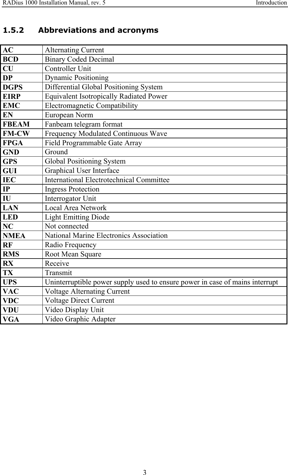
![RADius 1000 Installation Manual, rev. 5 Introduction 1 1. INTRODUCTION 1.1 About this manual This manual contains the information necessary to install the RADius 1000 on a vessel. For all other product information, please consult the RADius 1000 User's Manual, reference [2]. This manual is organised into the following chapters: Chapter 1 Introduction - A brief presentation of the RADius 1000 Installation Manual with references and abbreviations. Chapter 2 Specifications - Describes the physical dimensions, required power, environmental and cable specifications. Chapter 3 Installation - Presents procedures to be followed for a typical ship installation with recommendations on location of the different parts, mechanical and electrical installation and how to set up the product. Chapter 4 Installation drawings - Contains outline drawings showing the mechanical dimensions of the different parts of the RADius 1000. Chapter 5 Parts list - Lists the parts in the RADius 1000 system. In this manual the following notations are used: WARNING! Used when it is necessary to warn personnel that a risk of injury or death exists if care is not exercised. Caution! Used to warn the reader that a risk of damage to the equipment exists if care is not exercised. Note! Used to draw the reader's attention to a comment or some important information. 1.2 FCC part 15 statement This equipment has been tested and found to comply with the limits for a Class A digital device, pursuant to Part 15 of the FCC Rules. These limits are designed to provide reasonable protection against harmful interference when the equipment is operated in a marine and/or commercial environment. This equipment generates, uses and can radiate radio frequency energy and, if not installed and used in accordance with the instruction manual, may cause harmful interference to radio communications. The equipment is not intended for operation in](https://usermanual.wiki/Kongsberg-Seatex-AS/KSXRADIUS/User-Guide-789511-Page-11.png)
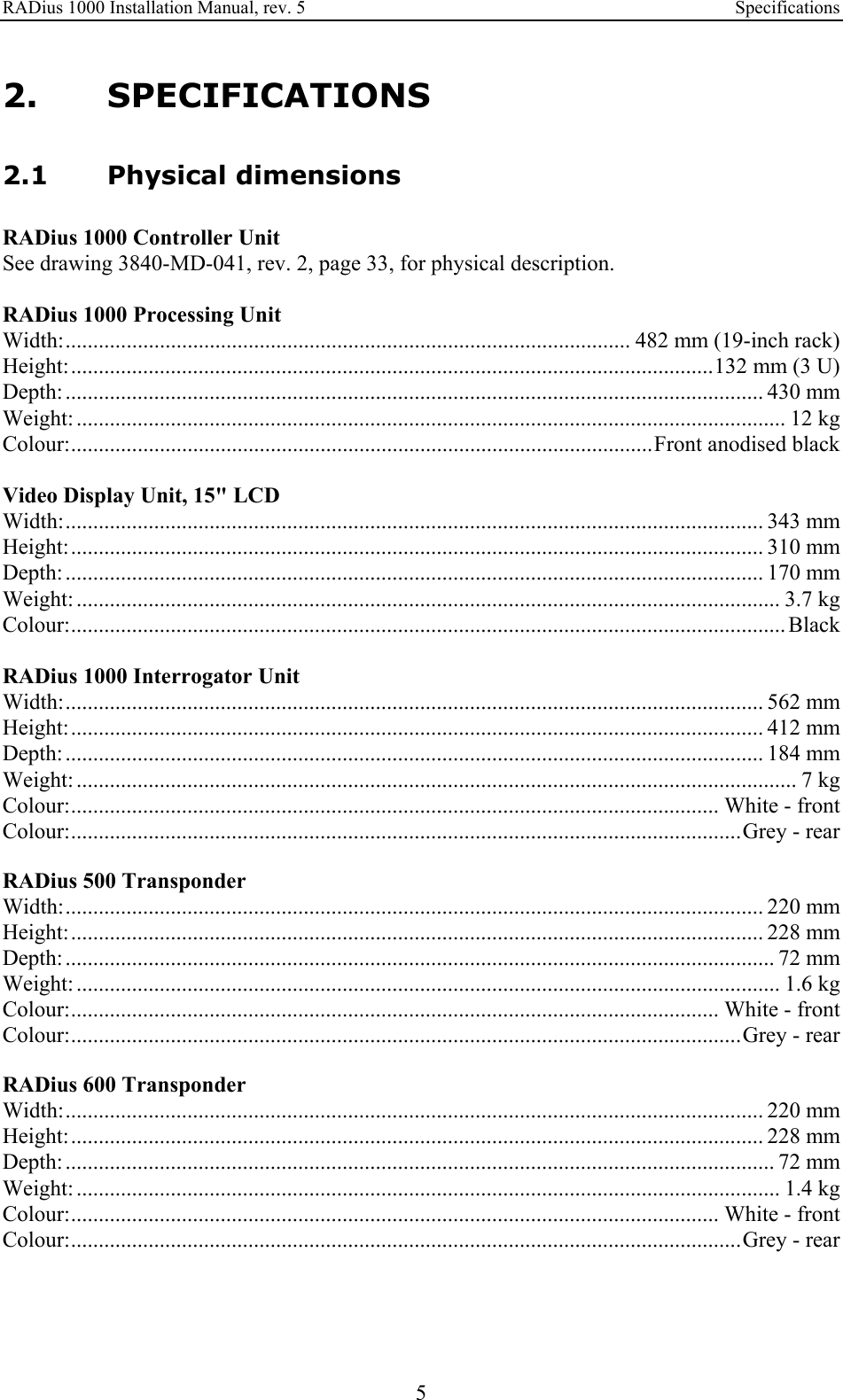
![RADius 1000 Installation Manual, rev. 5 Introduction 2 a residential area. Operation in such an area is likely to cause harmful interference in which case the user will be required to correct the interference at his own expense. Additional information to the user: Changes or modifications not expressly approved by Kongsberg Seatex AS will void the user's authority to operate the equipment. 1.3 FCC RF exposure compliance This device conforms with FCC RF radiation exposure limits set forth for an uncontrolled environment. The antenna used for this transmitter must be installed to provide a separation distance of at least 20 cm from all persons and must not be co-located or operating in conjunction with any other antenna or transmitter. WARNING! The RADius must be mounted with a separation distance of at least 20 cm from any humans. 1.4 References [1] NMEA 0183 Standard for interfacing marine electronic devices, Version 2.3 [2] RADius 1000 User's Manual [3] Man_inst_RADius_600X [4] Man_inst_RADius_500X 1.5 Definitions, abbreviations and acronyms 1.5.1 Definitions host system In this manual defined as Navigation computers, Dynamic Positioning Systems, etc, receiving data from RADius. Interrogator The Interrogator transmits signals and receives the reflected signals from the Transponder(s). Based on this, it calculates the distance and bearing to one or more transponders. Mounted on the DP vessel. Transponder The Transponder reflects the signals transmitted from the Interrogator. Mounted on the remote object/vessel. Latency The time it takes from the actual measurement is made until the telegram is transmitted on the serial port.](https://usermanual.wiki/Kongsberg-Seatex-AS/KSXRADIUS/User-Guide-789511-Page-12.png)

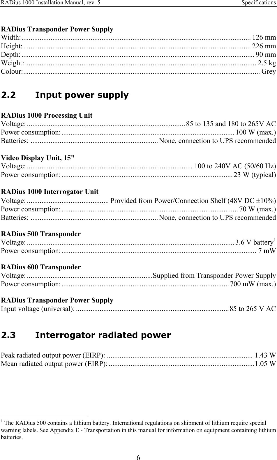


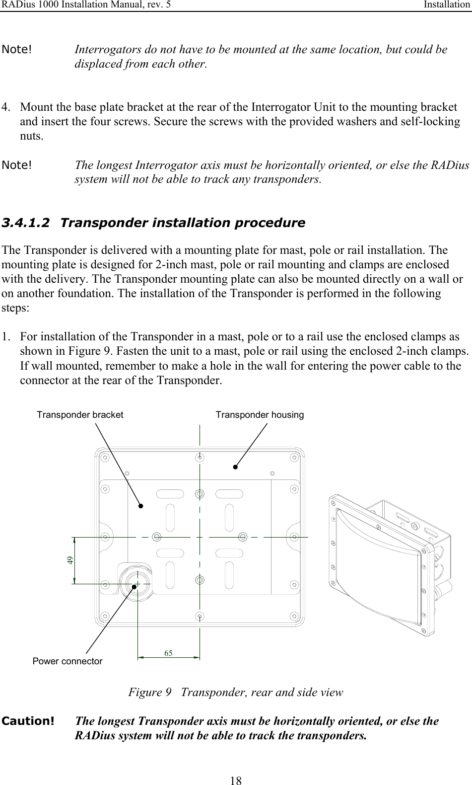
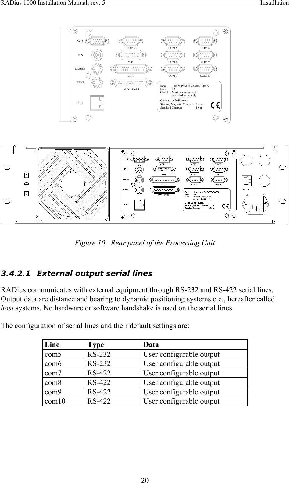
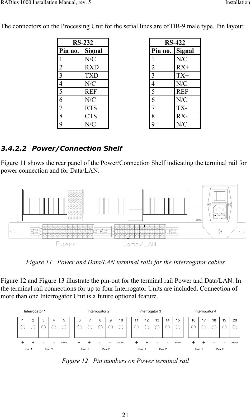
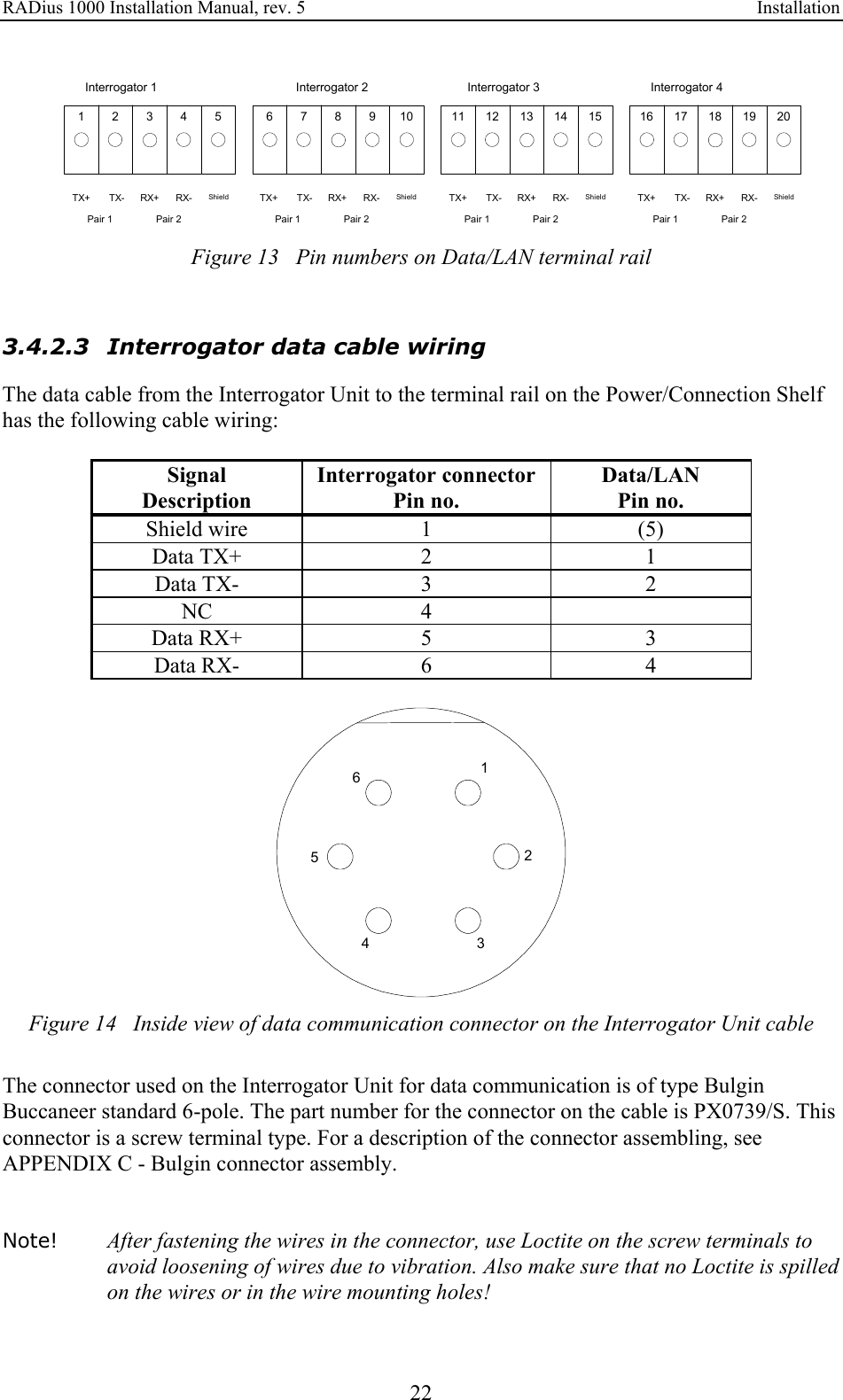
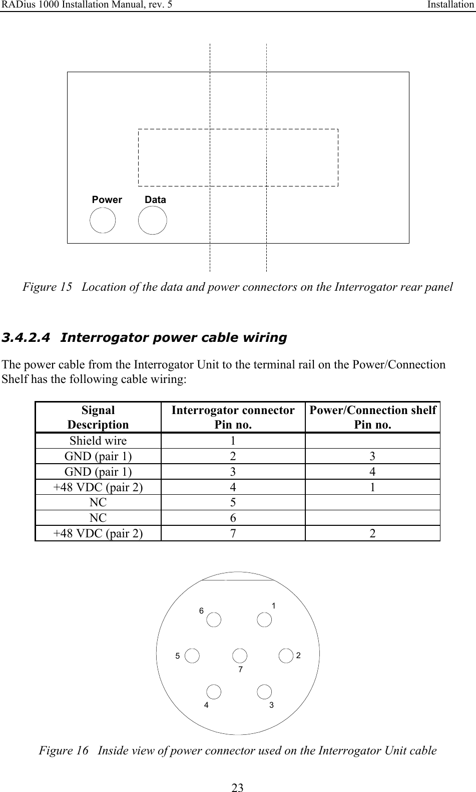
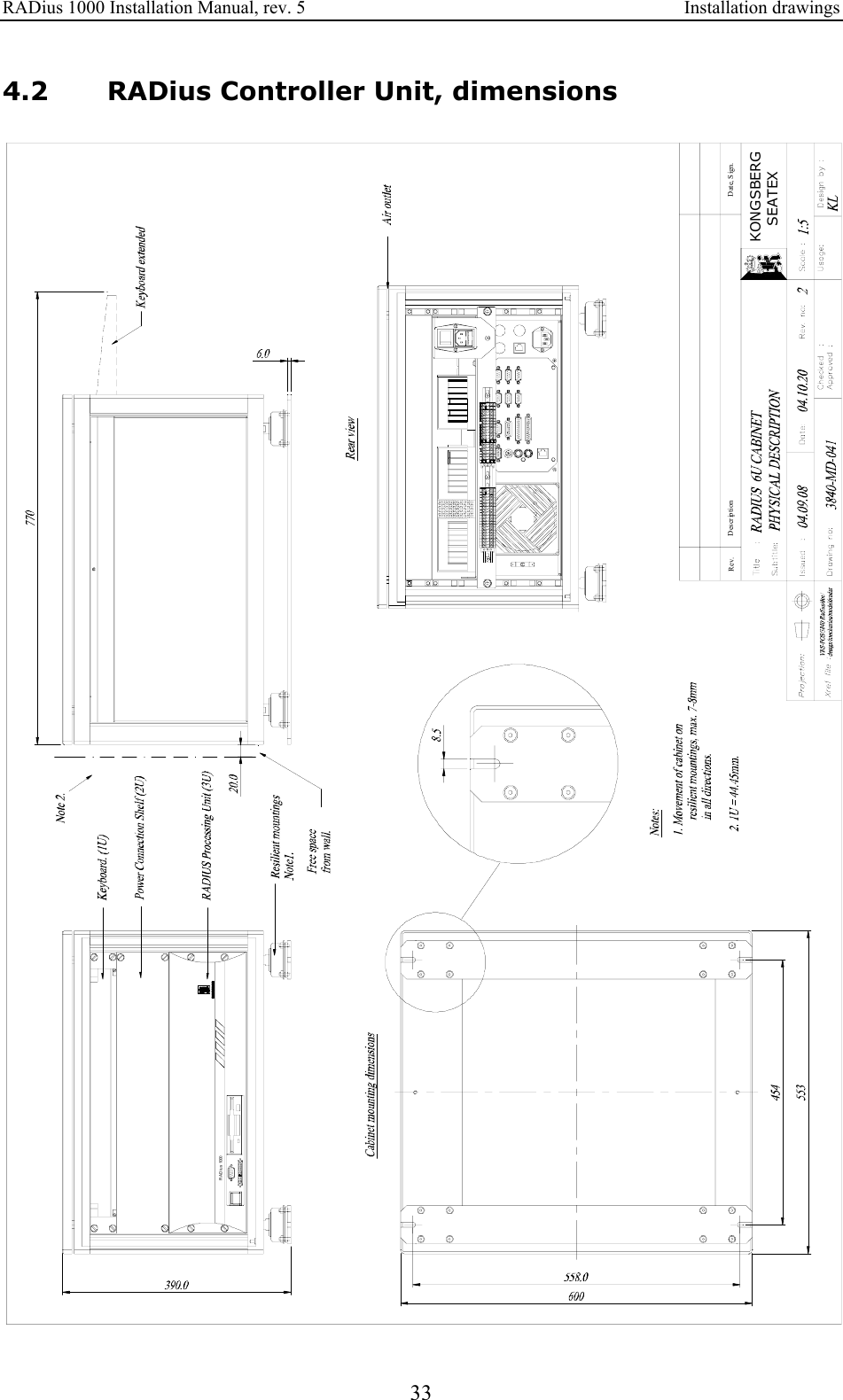
![RADius 1000 Installation Manual, rev. 5 Installation 19 3.4.1.3 Transponder Power Supply installation procedure The Transponder Power Supply must be securely mounted. Note! See References [3] and [4] for the installation of EX approved transponders. 3.4.1.4 Controller Unit installation procedure The cabinet must be securely mounted. Drilling plan for the resilient mounting is included in the attached drawing 3840-MD-041 on page 33. Caution! The power to the cabinet must be connected to a grounded mains outlet. This applies to both the Processing Unit and Power Connection Shelf. 3.4.1.5 VDU installation procedure Connect the VDU to the location labelled VGA at the rear panel of the Processing Unit. 3.4.2 Electrical installation The electrical installation consists of: • Connecting a power cable between the Interrogator Unit and the 48 VDC power located on the Power/Connection Shelf. • Connecting the data cable between the Interrogator Unit and Data/LAN connector on the Power/Connection Shelf. • Connecting cables with output data between the Processing Unit and external equipment (optional). • Connecting the Video Display Unit and the keyboard to the Processing Unit (optional). • Supplying 110/230 VAC power to the Processing Unit and the Video Display Unit. • Connecting 110/230VAC to the Power/Connection Shelf. • Connecting a power cable between the Transponder and the Transponder power supply.](https://usermanual.wiki/Kongsberg-Seatex-AS/KSXRADIUS/User-Guide-789511-Page-29.png)
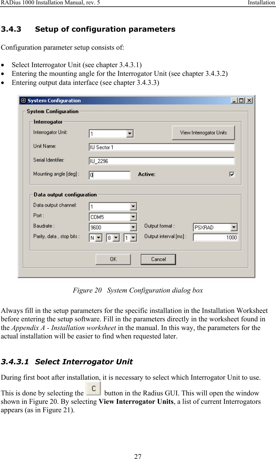
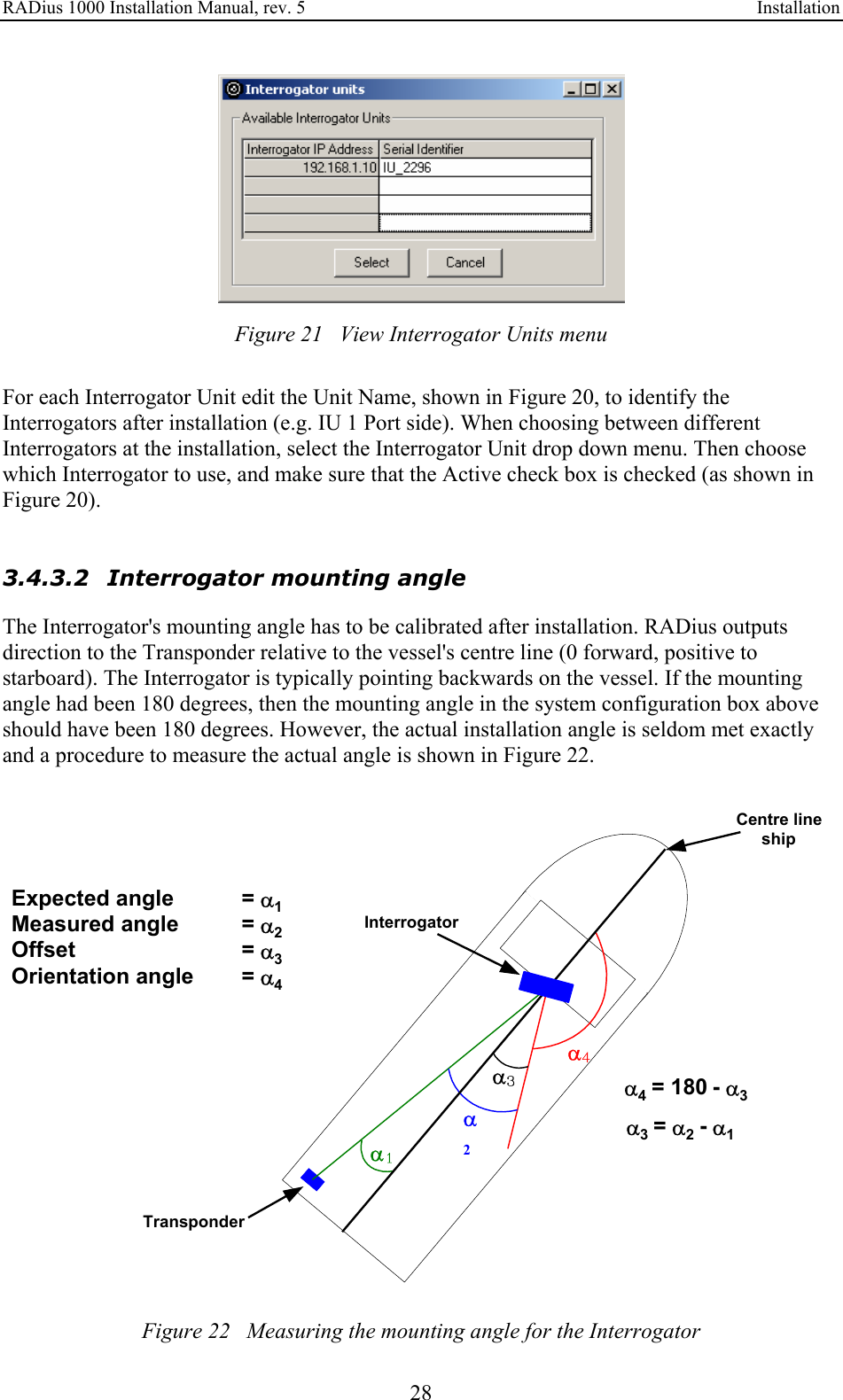
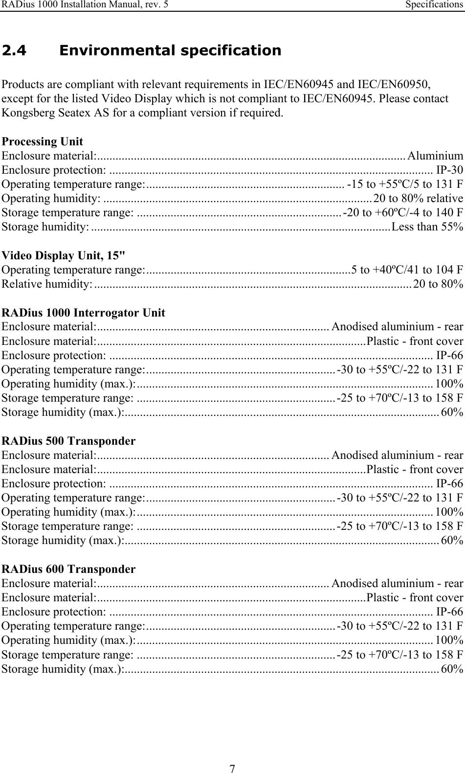
![RADius 1000 Installation Manual, rev. 5 Installation 29 In this example the Transponder is mounted at the stern of the vessel. 1. The location of the Transponder is measured relative to the centre line of the vessel and the Expected angle , α1, is calculated. 2. The system measures the angle to the Transponder, Measured angle: α2, and the offset from the expected angle, Offset angle: α3, is computed. 3. Then the Mounting angle, α4, can be computed based on the expected mounting angle (180° in the example above) and the computed installation Offset angle, α3. Figure 23 Interrogator mounting angle 3.4.3.3 Data output The Processing Unit has to be set up to output data to a DP system, following the procedure below: 1. Select which data output channel that is to be configured. This is usually channel 1. 2. Select which port that is going to be used. 3. Configure the port settings according to the settings on the host system. 4. Select the wanted output format. PSXRAD, FBEAM, ARTEMIS and ABB DP are available. For a description of the different formats, see Appendix B - Output Protocols. 5. Set the wanted output interval [ms]. The default value is 1000. This gives an output frequency of 1 Hz (one telegram per second). Figure 24 Data output configuration](https://usermanual.wiki/Kongsberg-Seatex-AS/KSXRADIUS/User-Guide-789511-Page-39.png)

![RADius 1000 Installation Manual, rev. 5 Appendix A - Installation worksheet 39 APPENDIX A - INSTALLATION WORKSHEET Vessel RADius serial no. IU serial no. Place Date Installed by Signature Vessel Geometry Vessel Dimension: Length [m] Width [m] Height [m] Centre of Gravity (CG) Location: From CG to AP (Aft Point) [m] (positive forward of CG) From CG to CL (Centre Line) [m] (positive to starboard of CG) From CG to the Keel [m] (positive below CG) Vessel Description Vessel Data: Vessel Type and Name Vessel Owner Country of Origin Management: Manager Phone Number RADius: RADius Owner RADius Manager Interrogator Mounting Angle Heading offset (Reference - Interrogator reading) [deg] Reference [deg] Interrogator [deg]] Data Output – Digital RS-232/422 Output Configuration Device Line (com) Electric 232/422 Baud rate Parity(st. n) Data bits(st. 8) Stop bits(st.1) Interval [s] Format Out Port #1](https://usermanual.wiki/Kongsberg-Seatex-AS/KSXRADIUS/User-Guide-789511-Page-49.png)

![RADius 1000 Installation Manual, rev. 5 Appendix B – Output Protocols 41 APPENDIX B - OUTPUT PROTOCOLS The available output data formats are as follows: Name Format no. Description PSXRAD 1 NMEA proprietary messages Fanbeam BCD telegram 2 Fanbeam binary format ARTEMIS 3 Pseudo Artemis, ASCII 17 bytes format ABB DP 4 Pseudo Fanbeam, ASCII 333 bytes adapted for ABB DP. 5.1 PSXRAD, NMEA proprietary format The NMEA format is an ASCII text format based on the NMEA 0183 standard defined in [1]. RADius utilises the proprietary PSXRAD format described below. Format: Note that this telegram is repeated for every Transponder tracked. The field marked ss is a sequence number indicating what telegram this is of a total of the number of transponders initiated for tracking (indicated by field nn). $PSXRAD,I,hhmmss.ss,nn,ss,tid,rrrr.rr,aa.a,bbb.bb,ss.s,±vv.vv,ff.f,±dd.dd,sn,S*cc<cr><lf> I ID for Interrogator, range 0-9 hhmmss.ss Time of position hour, minutes, seconds nn Number of transponders set up for tracking, range 0 – 99 ss Sequence number (multiple transponders), range 0 – (nn-1) tid Transponder ID, the number is the transponder frequency in 10KHz resolution. 150 is then 1.5 MHz transponder rrrr.rr Range in meters, decimal centimetres aa.a Range accuracy estimate (1 σ level in m) bbb.bb Bearing to transponder 0.00 to 360.00 degrees ss.s Bearing accuracy estimate (1 σ level in deg) ±vv.vv Vertical angle to transponder (-90.0 - +90.0), the + sign is omitted when positive. ff.f Vertical angle accuracy estimate (1 σ level in deg) ±dd.dd Velocity relative to transponder (doppler) m/s, the + sign is omitted when positive. sn Signal to noise in DB 0 – 90, less than10 is not good, 10 – 15 is week, > 15 is good S Status 0 – 9 (0 – No reply (not tracking transponder), 1 – Other error, do not use, 2 – Range only, 3 – 8 TBD, 9 – Valid Status) *cc Computed checksum <cr> Carriage Return <lf> Line Feed The telegram above is repeated for all Interrogators installed in the RADius system](https://usermanual.wiki/Kongsberg-Seatex-AS/KSXRADIUS/User-Guide-789511-Page-51.png)
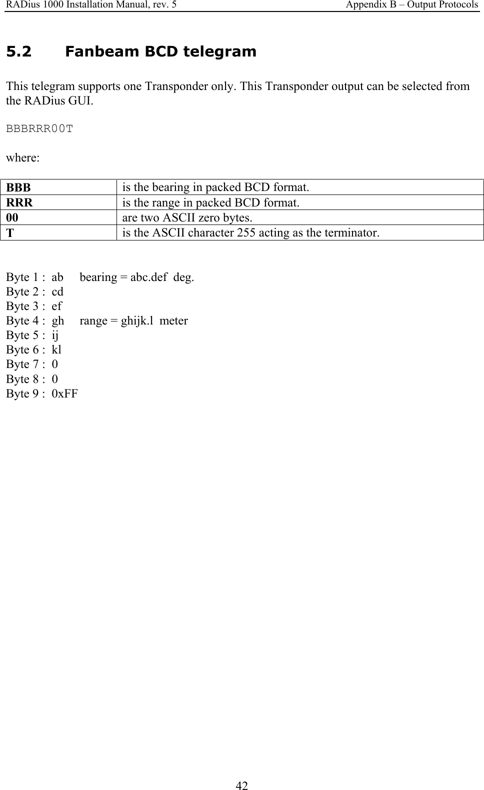
![RADius 1000 Installation Manual, rev. 5 Appendix B – Output Protocols 43 5.3 Pseudo Artemis telegram This telegram supports one Transponder only. This Transponder output can be selected from the RADius GUI. ABCDEF GHIJKL S[CR][LF] Where: ABCDEF is the range in decimeter, ASCII, ABCDE.F (m) GHIJKL is the bearing in degrees, ASCII, GHI.JKL (deg). S Status, '0' (0x30) is invalid data. '1' (0x31) is valid data Byte 1-6 : abcdef, Range in decimeter (abcde.f m). Byte 7 : Space Byte 8-13 : ghijkl, Bearing in degrees (ghi.jkl deg). Byte 14 : Space Byte 15 : s, Status flag, '0' (0x30) is invalid data, '1' (0x31) is valid data. Byte 16 : [CR], Carriage Return Byte 17 : [LF], Line Feed Note that this telegram differs from Artemis When it comes to bearing. Bearing in Artemis is relative to North. Bearing from RADius is relative to vessels heading.](https://usermanual.wiki/Kongsberg-Seatex-AS/KSXRADIUS/User-Guide-789511-Page-53.png)
![RADius 1000 Installation Manual, rev. 5 Appendix B – Output Protocols 44 5.4 ABB DP telegram This telegram supports one Transponder only. This Transponder output can be selected from the RADius GUI. SN,RRRR.R,BBB.BB,TTT,S,HH:MM:SS[CR][LF] Where: SN Signal to Noise Ratio (dBm), ASCII RRR.R Is the range in meters, ASCII BBB.BB Bearing in degrees, ASCII TTT Transponder ID, ASCII S Status, ASCII, 0 – 9 (0 – No reply (not tracking transponder), 1 – Other error, do not use, 2 – Range only, 3 – 8 TBD, 9 – Valid Status) HH:MM:SS Time, ASCII, Hour : Minutes : Seconds from system time. Byte 1-2 : SN. Byte 3 : Comma Character Byte 4-9 : RRR.R, Range (meters) Byte 10 : Comma Character Byte 11-16 : BBB.BB, Bearing (degrees) Byte 17 : Comma Character Byte 18-20 : TTT, Transponder ID (range 150 – 300) Byte 21 : Comma Character Byte 22 : Status, See above Byte 23 : Comma Character Byte 24-31 : Time Byte 32 : [CR], Carriage Return Byte 33 : [LF], Line Feed](https://usermanual.wiki/Kongsberg-Seatex-AS/KSXRADIUS/User-Guide-789511-Page-54.png)