Kongsberg Seatex AS KSXRADIUS Short-Range Relative Positioning System User Manual
Kongsberg Seatex AS Short-Range Relative Positioning System
User Manual
RADius 1000
Installation Manual
Issued: 2006-11-30
Blank page
III
Notice
• All rights reserved. Reproduction of any of this manual in any form whatsoever without
prior written permission from Kongsberg Seatex AS is forbidden.
• The content of this manual is subject to change without notice.
• All efforts have been made to ensure the accuracy of the contents of this manual.
However, should any errors be detected, Kongsberg Seatex AS would greatly appreciate
being informed of them.
Copyright 2006 by Kongsberg Seatex AS. All rights reserved.
Kongsberg Seatex AS
Pirsenteret, N-7462 Trondheim, Norway
Telephone: +47 73 54 55 00
Facsimile: +47 73 51 50 20
Duty phone: +47 73 50 21 11
E-mail: km.seatex@kongsberg.com
www.km.kongsberg.com/seatex
IV
Blank page

V
Revision log
Document ID Rev. Date Reason for revision Approved
(sign)
Man_inst_radius1000 0 2004-05-15 First version FOS
Man_inst_radius1000 1 2004-10-29 Issued after comments from
Kongsberg Maritime
TSW
Man_inst_radius1000 2 2004-12-06 Note on lithium battery TSW
Man_inst_radius1000 3 2005-02-07 Corrected cable part numbers TSW
Man_inst_radius1000 4 2006-02-20 Added new interface telegram
descriptions.
New installation cable part
number.
Added UPS recommendations
for transponders.
TSW
Man_inst_radius1000 5 2006-11-30 Updated manual to be
compatible with SW version
1.05.xx
FCC statement and RF
exposure info added, WEEE
note removed. Definitions
altered.
Transponder temperature range
adjusted and mean radiated
power inserted.
New Processing Unit front
view with LEDs
New and updated drawings
Change of note status from
Caution to Warning, page 25.
Dual interrogator information
added.
HR
VI
Blank page
VII
Table of contents
1. INTRODUCTION............................................................................................................... 1
1.1 About this manual ........................................................................................................ 1
1.2 FCC part 15 statement.................................................................................................. 1
1.3 FCC RF exposure compliance ..................................................................................... 2
1.4 References.................................................................................................................... 2
1.5 Definitions, abbreviations and acronyms..................................................................... 2
1.5.1 Definitions........................................................................................................ 2
1.5.2 Abbreviations and acronyms............................................................................ 3
2. SPECIFICATIONS............................................................................................................. 5
2.1 Physical dimensions..................................................................................................... 5
2.2 Input power supply....................................................................................................... 6
2.3 Interrogator radiated power.......................................................................................... 6
2.4 Environmental specification ........................................................................................ 7
2.5 Cables........................................................................................................................... 8
3. INSTALLATION ................................................................................................................ 9
3.1 General information ..................................................................................................... 9
3.2 Logistics ..................................................................................................................... 11
3.3 Location of the system parts ...................................................................................... 12
3.3.1 The Interrogator Unit ..................................................................................... 12
3.3.2 The Transponders........................................................................................... 14
3.3.3 Transponder Power Supply ............................................................................ 14
3.3.4 The Controller Unit ........................................................................................ 14
3.3.5 The Video Display Unit ................................................................................. 15
3.4 Installation procedures ............................................................................................... 15
3.4.1 Mechanical installation .................................................................................. 15
3.4.1.1 Interrogator installation procedure................................................... 16
3.4.1.2 Transponder installation procedure.................................................. 18
3.4.1.3 Transponder Power Supply installation procedure .......................... 19
3.4.1.4 Controller Unit installation procedure ............................................. 19
3.4.1.5 VDU installation procedure ............................................................. 19
3.4.2 Electrical installation...................................................................................... 19
3.4.2.1 External output serial lines............................................................... 20
3.4.2.2 Power/Connection Shelf .................................................................. 21
3.4.2.3 Interrogator data cable wiring.......................................................... 22
3.4.2.4 Interrogator power cable wiring....................................................... 23
3.4.2.5 High Gain Transponder power cable wiring and installation .......... 24
3.4.2.6 Low Power Transponder battery switch .......................................... 25
3.4.2.7 Interrogator Cable installation procedure ........................................ 25
VIII
3.4.3 Setup of configuration parameters ................................................................. 27
3.4.3.1 Select Interrogator Unit.................................................................... 27
3.4.3.2 Interrogator mounting angle............................................................. 28
3.4.3.3 Data output....................................................................................... 29
4. INSTALLATION DRAWINGS....................................................................................... 31
4.1 RADius Processing Unit, dimensions........................................................................ 32
4.2 RADius Controller Unit, dimensions......................................................................... 33
4.3 RADius Interrogator, dimensions .............................................................................. 34
4.4 RADius Transponder 500 Low Power, dimensions................................................... 35
4.5 RADius Transponder 600 High Gain, dimensions .................................................... 36
5. PARTS LIST ..................................................................................................................... 37
APPENDIX A - INSTALLATION WORKSHEET ............................................................ 39
APPENDIX B - OUTPUT PROTOCOLS............................................................................ 41
5.1 PSXRAD, NMEA proprietary format........................................................................ 41
5.2 Fanbeam BCD telegram............................................................................................. 42
5.3 Pseudo Artemis telegram ........................................................................................... 43
5.4 ABB DP telegram ...................................................................................................... 44
APPENDIX C - BULGIN CONNECTOR ASSEMBLY .................................................... 45
APPENDIX D - TRANSPONDER ID SETTINGS ............................................................. 47
APPENDIX E - TRANSPORTATION................................................................................. 49
Index ........................................................................................................................................ 51
Reader's comments ................................................................................................................ 53

IX
List of illustrations
Figure 1 RADius 1000 system, single Interrogator ................................................................. 9
Figure 2 RADius 1000 system, dual Interrogator .................................................................. 10
Figure 3 Typical operational scenario for a supply vessel operation, single Interrogator ...... 13
Figure 4 Typical operational scenario for a supply vessel operation, dual Interrogator......... 13
Figure 5 Interrogator mounting bracket ................................................................................. 16
Figure 6 Interrogator Unit mounted to mast or pole, top view .............................................. 16
Figure 7 Interrogator Unit mounted to rail, top view............................................................. 17
Figure 8 Dual Interrogator Unit mounted to mast or pole, top view...................................... 17
Figure 9 Transponder, rear and side view.............................................................................. 18
Figure 10 Rear panel of the Processing Unit ......................................................................... 20
Figure 11 Power and Data/LAN terminal rails for the Interrogator cables............................ 21
Figure 12 Pin numbers on Power terminal rail ...................................................................... 21
Figure 13 Pin numbers on Data/LAN terminal rail................................................................ 22
Figure 14 Inside view of data communication connector on the Interrogator Unit cable...... 22
Figure 15 Location of the data and power connectors on the Interrogator rear panel ........... 23
Figure 16 Inside view of power connector used on the Interrogator Unit cable.................... 23
Figure 17 Inside view of power connector on the Transponder cable ................................... 24
Figure 18 Transponder Power Supply cable connections ...................................................... 25
Figure 19 Processing Unit front view showing status LEDs ................................................. 26
Figure 20 System Configuration dialog box .......................................................................... 27
Figure 21 View Interrogator Units menu ............................................................................... 28
Figure 22 Measuring the mounting angle for the Interrogator............................................... 28
Figure 23 Interrogator mounting angle .................................................................................. 29
Figure 24 Data output configuration ...................................................................................... 29
Figure 25 Bulgin connector assembly.................................................................................... 45
Figure 26 Dangerous goods class 9 UN-3091........................................................................ 49
List of drawings
Drawing no. Title Revision No. of sheets
31438-MA-010 RADius Processing Unit, dimensions 4 1
3840-MD-041 RADius Controller Unit, dimensions 2 1
3840-MA-011 Interrogator, dimensions 3 1
3840-MA-020 Transponder, dimensions 1 1
3840-MA-026 Transponder dimensions, 600 High Gain 1 1
X
Blank page

RADius 1000 Installation Manual, rev. 5 Introduction
1
1. INTRODUCTION
1.1 About this manual
This manual contains the information necessary to install the RADius 1000 on a vessel. For
all other product information, please consult the RADius 1000 User's Manual, reference [2].
This manual is organised into the following chapters:
Chapter 1 Introduction - A brief presentation of the RADius 1000 Installation Manual with
references and abbreviations.
Chapter 2 Specifications - Describes the physical dimensions, required power,
environmental and cable specifications.
Chapter 3 Installation - Presents procedures to be followed for a typical ship installation
with recommendations on location of the different parts, mechanical and electrical
installation and how to set up the product.
Chapter 4 Installation drawings - Contains outline drawings showing the mechanical
dimensions of the different parts of the RADius 1000.
Chapter 5 Parts list - Lists the parts in the RADius 1000 system.
In this manual the following notations are used:
WARNING! Used when it is necessary to warn personnel that a risk of injury
or death exists if care is not exercised.
Caution! Used to warn the reader that a risk of damage to the equipment exists if
care is not exercised.
Note! Used to draw the reader's attention to a comment or some important
information.
1.2 FCC part 15 statement
This equipment has been tested and found to comply with the limits for a Class A digital
device, pursuant to Part 15 of the FCC Rules. These limits are designed to provide reasonable
protection against harmful interference when the equipment is operated in a marine and/or
commercial environment. This equipment generates, uses and can radiate radio frequency
energy and, if not installed and used in accordance with the instruction manual, may cause
harmful interference to radio communications. The equipment is not intended for operation in

RADius 1000 Installation Manual, rev. 5 Introduction
2
a residential area. Operation in such an area is likely to cause harmful interference in which
case the user will be required to correct the interference at his own expense.
Additional information to the user:
Changes or modifications not expressly approved by Kongsberg Seatex AS will void the
user's authority to operate the equipment.
1.3 FCC RF exposure compliance
This device conforms with FCC RF radiation exposure limits set forth for an uncontrolled
environment. The antenna used for this transmitter must be installed to provide a separation
distance of at least 20 cm from all persons and must not be co-located or operating in
conjunction with any other antenna or transmitter.
WARNING! The RADius must be mounted with a separation distance of at
least 20 cm from any humans.
1.4 References
[1] NMEA 0183 Standard for interfacing marine electronic devices, Version 2.3
[2] RADius 1000 User's Manual
[3] Man_inst_RADius_600X
[4] Man_inst_RADius_500X
1.5 Definitions, abbreviations and acronyms
1.5.1 Definitions
host system In this manual defined as Navigation computers, Dynamic
Positioning Systems, etc, receiving data from RADius.
Interrogator The Interrogator transmits signals and receives the reflected signals
from the Transponder(s). Based on this, it calculates the distance and
bearing to one or more transponders. Mounted on the DP vessel.
Transponder The Transponder reflects the signals transmitted from the
Interrogator. Mounted on the remote object/vessel.
Latency The time it takes from the actual measurement is made until the
telegram is transmitted on the serial port.

RADius 1000 Installation Manual, rev. 5 Introduction
3
1.5.2 Abbreviations and acronyms
AC Alternating Current
BCD Binary Coded Decimal
CU Controller Unit
DP Dynamic Positioning
DGPS Differential Global Positioning System
EIRP Equivalent Isotropically Radiated Power
EMC Electromagnetic Compatibility
EN European Norm
FBEAM Fanbeam telegram format
FM-CW Frequency Modulated Continuous Wave
FPGA Field Programmable Gate Array
GND Ground
GPS Global Positioning System
GUI Graphical User Interface
IEC International Electrotechnical Committee
IP Ingress Protection
IU Interrogator Unit
LAN Local Area Network
LED Light Emitting Diode
NC Not connected
NMEA National Marine Electronics Association
RF Radio Frequency
RMS Root Mean Square
RX Receive
TX Transmit
UPS Uninterruptible power supply used to ensure power in case of mains interrupt
VAC Voltage Alternating Current
VDC Voltage Direct Current
VDU Video Display Unit
VGA Video Graphic Adapter

RADius 1000 Installation Manual, rev. 5 Introduction
4
Blank page

RADius 1000 Installation Manual, rev. 5 Specifications
5
2. SPECIFICATIONS
2.1 Physical dimensions
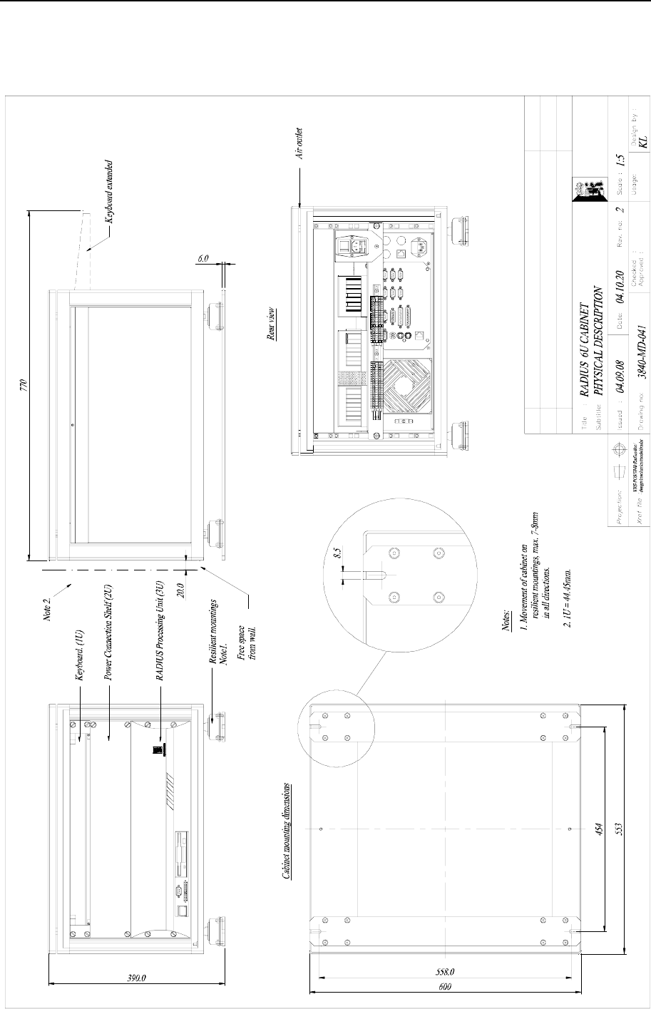
RADius 1000 Controller Unit
See drawing 3840-MD-041, rev. 2, page 33, for physical description.
RADius 1000 Processing Unit
Width:...................................................................................................... 482 mm (19-inch rack)
Height:....................................................................................................................132 mm (3 U)
Depth: .............................................................................................................................. 430 mm
Weight: ................................................................................................................................ 12 kg
Colour:.........................................................................................................Front anodised black
Video Display Unit, 15" LCD
Width:.............................................................................................................................. 343 mm
Height:............................................................................................................................. 310 mm
Depth: .............................................................................................................................. 170 mm
Weight: ............................................................................................................................... 3.7 kg
Colour:................................................................................................................................. Black
RADius 1000 Interrogator Unit
Width:.............................................................................................................................. 562 mm
Height:............................................................................................................................. 412 mm
Depth: .............................................................................................................................. 184 mm
Weight: .................................................................................................................................. 7 kg
Colour:..................................................................................................................... White - front
Colour:.........................................................................................................................Grey - rear
RADius 500 Transponder
Width:.............................................................................................................................. 220 mm
Height:............................................................................................................................. 228 mm
Depth: ................................................................................................................................ 72 mm
Weight: ............................................................................................................................... 1.6 kg
Colour:..................................................................................................................... White - front
Colour:.........................................................................................................................Grey - rear
RADius 600 Transponder
Width:.............................................................................................................................. 220 mm
Height:............................................................................................................................. 228 mm
Depth: ................................................................................................................................ 72 mm
Weight: ............................................................................................................................... 1.4 kg
Colour:..................................................................................................................... White - front
Colour:.........................................................................................................................Grey - rear

RADius 1000 Installation Manual, rev. 5 Specifications
6
RADius Transponder Power Supply
Width:.............................................................................................................................. 126 mm
Height:............................................................................................................................. 226 mm
Depth: ................................................................................................................................ 90 mm
Weight: ............................................................................................................................... 2.5 kg
Colour:.................................................................................................................................. Grey
2.2 Input power supply
RADius 1000 Processing Unit
Voltage: ....................................................................................... 85 to 135 and 180 to 265V AC
Power consumption:............................................................................................... 100 W (max.)
Batteries: ...................................................................... None, connection to UPS recommended
Video Display Unit, 15"
Voltage: ........................................................................................... 100 to 240V AC (50/60 Hz)
Power consumption:.............................................................................................. 23 W (typical)
RADius 1000 Interrogator Unit
Voltage: ............................................. Provided from Power/Connection Shelf (48V DC ±10%)
Power consumption:................................................................................................. 70 W (max.)
Batteries: ...................................................................... None, connection to UPS recommended
RADius 500 Transponder
Voltage: .................................................................................................................. 3.6 V battery1
Power consumption:........................................................................................................... 7 mW
RADius 600 Transponder
Voltage: .....................................................................Supplied from Transponder Power Supply
Power consumption:............................................................................................ 700 mW (max.)
RADius Transponder Power Supply
Input voltage (universal): ....................................................................................85 to 265 V AC
2.3 Interrogator radiated power
Peak radiated output power (EIRP): ................................................................................ 1.43 W
Mean radiated output power (EIRP): ................................................................................1.05 W
1 The RADius 500 contains a lithium battery. International regulations on shipment of lithium require special
warning labels. See Appendix E - Transportation in this manual for information on equipment containing lithium
batteries.

RADius 1000 Installation Manual, rev. 5 Specifications
7
2.4 Environmental specification
Products are compliant with relevant requirements in IEC/EN60945 and IEC/EN60950,
except for the listed Video Display which is not compliant to IEC/EN60945. Please contact
Kongsberg Seatex AS for a compliant version if required.
Processing Unit
Enclosure material:..................................................................................................... Aluminium
Enclosure protection: .......................................................................................................... IP-30
Operating temperature range:................................................................. -15 to +55ºC/5 to 131 F
Operating humidity: ........................................................................................20 to 80% relative
Storage temperature range: ...................................................................-20 to +60ºC/-4 to 140 F
Storage humidity: ..................................................................................................Less than 55%
Video Display Unit, 15"
Operating temperature range:...................................................................5 to +40ºC/41 to 104 F
Relative humidity:........................................................................................................20 to 80%
RADius 1000 Interrogator Unit
Enclosure material:............................................................................ Anodised aluminium - rear
Enclosure material:........................................................................................Plastic - front cover
Enclosure protection: .......................................................................................................... IP-66
Operating temperature range:..............................................................-30 to +55ºC/-22 to 131 F
Operating humidity (max.):................................................................................................. 100%
Storage temperature range: .................................................................-25 to +70ºC/-13 to 158 F
Storage humidity (max.):.......................................................................................................60%
RADius 500 Transponder
Enclosure material:............................................................................ Anodised aluminium - rear
Enclosure material:........................................................................................Plastic - front cover
Enclosure protection: .......................................................................................................... IP-66
Operating temperature range:..............................................................-30 to +55ºC/-22 to 131 F
Operating humidity (max.):................................................................................................. 100%
Storage temperature range: .................................................................-25 to +70ºC/-13 to 158 F
Storage humidity (max.):.......................................................................................................60%
RADius 600 Transponder
Enclosure material:............................................................................ Anodised aluminium - rear
Enclosure material:........................................................................................Plastic - front cover
Enclosure protection: .......................................................................................................... IP-66
Operating temperature range:..............................................................-30 to +55ºC/-22 to 131 F
Operating humidity (max.):................................................................................................. 100%
Storage temperature range: .................................................................-25 to +70ºC/-13 to 158 F
Storage humidity (max.):.......................................................................................................60%

RADius 1000 Installation Manual, rev. 5 Specifications
8
RADius Transponder Power Supply
Enclosure material:..................................................................................................... Aluminium
Enclosure protection: .......................................................................................................... IP-65
Operating temperature range:................................................................. -15 to +55ºC/5 to 131 F
Operating humidity (max.):................................................................................................. 100%
Storage temperature range: .................................................................-25 to +70ºC/-13 to 158 F
Storage humidity (max.):.......................................................................................................60%
2.5 Cables
Possible cable types:
Interrogator to Processing Unit Data Cable
Type 1:.....................................Draka type TI (C) 60 V, shipline, 2x2x0.5 mm2 (Halogen free)1
Draka part number:......................................................................... 839202, El-number 1045881
Type 2:.................................... Draka type TI (C) 250 V, shipline, 2x2x0.5 mm2 (Halogen free)
Draka part number:.......................................................................................................... 832002,
Cable resistance, Type1 and Type 2: ........................................................................ 40 Ohm/km
Diameter overall, Type 1:............................................................................................... 6.5 ± 0.5
Diameter overall, Type 2:.................................................................................................. 6 ± 0.5
Maximum length: ................................................................................................................. 60 m
Flame retardation: ................................................................................................ IEC 60332-1/3
Interrogator Power Cable
Type:.............................................................................................................................. As above
Maximum length: ................................................................................................................. 60 m
Transponder Power Cable
Type:.............................................................................................................................. As above
Maximum length: ............................................................................................................... 200 m
Note! The data cable must be twisted pair cable! If other cable types are used the
maximum diameter should not exceed 7.5
±
0.5 mm.
1 This type is likely to be obsolete in 2006
RADius 1000 Installation Manual, rev. 5 Installation
9
3. INSTALLATION
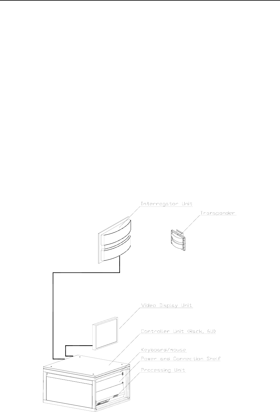
3.1 General information
This chapter describes a typical ship installation of the RADius system (EX approved
transponders are described in separate manuals). The standard system is supplied with the
following parts:
• A 19-inch rack (6U) (resiliently mounted)
• RADius 1000 Processing Unit (mounted in the rack)
• RADius 1000 Interrogator Unit
• RADius 500 Transponder
• VDU monitor for desktop mounting
• Keyboard with integrated mouse (1U)
• A power and connection shelf (2U) (mounted in the rack)
• Power and data cables between the Processing Unit and the Interrogator Unit
• Documentation
• Power supply - Transponder
Figure 1 RADius 1000 system, single Interrogator
RADius 1000 Installation Manual, rev. 5 Installation
10
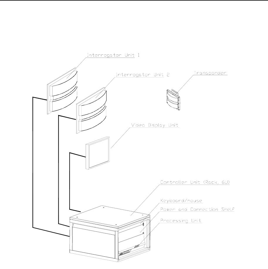
If a dual Interrogator system is needed, another RADius 1000 Interrogator Unit is added as
shown in Figure 2.
Figure 2 RADius 1000 system, dual Interrogator
In addition to the above delivered parts, the following is needed:
• Additional cables for output lines to external equipment
• Power cable to the Transponder
For external interfaces, electrical characteristics and data formats must be decided, and the
necessary cables and connectors made available. Mains cables for the Power/ Connection
Shelf and Processing Unit are also needed.

RADius 1000 Installation Manual, rev. 5 Installation
11
3.2 Logistics
WARNING! The RADius 500 contains a lithium battery inside the equipment
housing. The battery is completely covered by the transponder
housing and is watertight. Unless severe damage is made to the
housing there is no risk of explosion or fire. See Appendix E -
Transportation for labels and symbols on equipment package.
To avoid possible fire, explosion, leakage or burn hazard do not
open the sealed unit. Do not attempt to recharge, disassemble,
heat above +75° C / 167 F or incinerate.
Caution! The RADius 500 battery cannot be recharged and an attempt to do so
could result in a hazard. (Battery terminals are not accessible unless the
cover is destroyed or removed).
Inspect equipment for possible physical damage before installation. Make sure that no
damage is made to the cover of the RADius 1000 Interrogator unit, the RADius 600
Transponder and the RADius 500 low power.
WARNING! Defective cover, exposing battery, on RADius 500 may be
hazardous.
Safety: General safety guidelines to be followed when working in mast and on deck. See note
on battery in Appendix E - Transportation in this manual.
Personnel qualifications: Trained electrical workers.
Minimum number of personnel: 2, especially when mounting the Interrogator Unit to rail or mast.
Ship location: None.
Special tools required: None.
Note! Keep the original packaging (at least) for RADius 500. The package is equipped
with transport labels specific to content (lithium battery).

RADius 1000 Installation Manual, rev. 5 Installation
12
3.3 Location of the system parts
The following sections describe various procedures regarding mounting of the different
system parts:
3.3.1 The Interrogator Unit
For location of the Interrogator Unit, consider the following:
• The sector which the Interrogator is supposed to cover. The Interrogator has an operating
sector of 90 degrees in both vertical and horizontal direction.
• The longest Interrogator axis must be horizontally oriented.
• The Interrogator should be located high above sea level.
• The Interrogator should not be mounted close to the ship side, or other large metal
surfaces. This is to avoid multi path effects.
• The Interrogator needs free line of sight to the Transponders.
• The Interrogator should be mounted to a stiff mast, rail or wall to limit the risk of
mechanical resonances caused by vibration. Excessive (> 1 g rms) vibrations could affect
the quality of the measurements.
• During dual Interrogator installations, the two Interrogators should ideally be mounted
with a 90 degree difference as shown in Figure 8. This will make it possible to cover 180
degrees.
Note! The longest Interrogator axis must be horizontally oriented, or else the RADius
system will not be able to track any transponders.
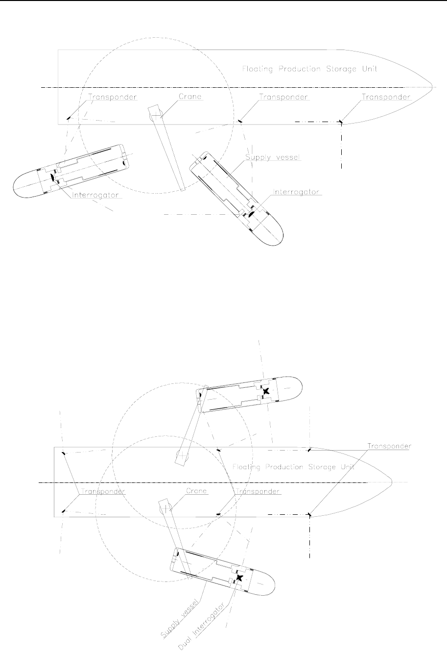
A typical operational scenario for a single Interrogator solution is shown in Figure 3. The
system will typically operate against several Transponders simultaneously and the
Interrogator should be installed in the direction where the vessel will see one or more
Transponders in the operational environment. For a supply vessel a good location for
installation can be outside railing on top of bridge roof, pointing aft. To avoid multi path
effects during operation, it is important not to locate the transponders close to the ship/rig
side.
RADius 1000 Installation Manual, rev. 5 Installation
13
Figure 3 Typical operational scenario for a supply vessel operation, single Interrogator
For supply vessels operating with different sides against an installation, it is highly
recommended to use a dual Interrogator system. A typical operational scenario for a dual
Interrogator solution is shown in Figure 3.
Figure 4 Typical operational scenario for a supply vessel operation, dual Interrogator

RADius 1000 Installation Manual, rev. 5 Installation
14
3.3.2 The Transponders
Please note that Transponders located at the same side of the vessel MUST have different
identification numbers (ID).
For location of the Transponders, consider the following:
• The Transponder is placed on a reference location, e.g. rail of rig, which is to be
positioned by an Interrogator.
• The orientation of the Transponder is optimised according to its 90-degree operating
sector (both vertical and horizontal) and to the operational location for the vessel(s)
containing the Interrogators.
• The longest Transponder axis must be horizontally oriented.
• The Transponder requires free line of sight to the Interrogators.
• The Transponder should be mounted to a stiff mast, rail or wall to limit the risk of
mechanical resonances caused by vibration.
• The RADius 600 High Gain Transponder shall preferably be mounted in a location not
too distant from its power supply (< 200 metres) in order to minimize cable resistance.
• The Transponder should not be mounted close to large metal surfaces (e.g. rig side) to
avoid multi path effects that could decrease accuracy.
Caution! The longest Transponder axis must be horizontally oriented or else the
RADius system will not be able to track the transponders.
3.3.3 Transponder Power Supply
Indoor mounting is recommended. Outdoor mounting may be allowed as the equipment is
ingress protected to IP65. The Transponder Power Supply shall preferably be mounted not too
distant from the Transponder (< 200 metres) in order to minimize cable resistance.
3.3.4 The Controller Unit
For location of the Controller Unit, consider the following:
• The Controller Unit must be resiliently mounted.
• The warranty will be void if the Processing Unit is removed from the cabinet.
• The unit is designed for indoor installation (protected environment) and should not be
exposed to heavy vibrations (exceeding 0,7 g RMS), transformers or similar.

RADius 1000 Installation Manual, rev. 5 Installation
15
• It is recommended that ventilation or air conditioning is provided in order to keep the
ambient operating temperature around +20°C. The best location is typically in the
instrument room or on the bridge, where good ventilation for the 19-inch rack can be
provided.
• It is recommended that the area around the unit is kept free from dust and static electricity.
• The air inlet and outlet on the unit must not be blocked. The unit has an internal fan and
requires free airflow from the rear and out to the sides of the unit.
• All connections to the unit are at the rear side and available space for cable connections
and service must be provided.
3.3.5 The Video Display Unit
For location of the table mounted Video Display Unit, consider the following:
• The unit is designed for installation in an indoor environment and for operation within the
temperature range. The best location is typically on a table in the instrument room or on
the bridge.
• The unit should be mounted close to the Controller Unit.
• The unit must be located and oriented in such a way that it is easy to see for the vessel
operator.
• It is recommended that the area around the unit is kept free from dust and static electricity.
3.4 Installation procedures
3.4.1 Mechanical installation
The mechanical installation consists of:
• Mounting the Interrogator(s) in a mast or to the rail.
• Mounting the Transponder at a suitable reference point.
• Mounting the Transponder Power Supply.
• Mounting the Controller Unit in the instrument room or bridge of the vessel.
• Mounting the VDU in a location easy to monitor for the vessel operator.
RADius 1000 Installation Manual, rev. 5 Installation
16
3.4.1.1 Interrogator installation procedure
The mechanical installation of the various parts is performed in the following steps:
1. Dismantle the mounting bracket shown in Figure 5 from the rear of the Interrogator Unit
if not already done.
Figure 5 Interrogator mounting bracket
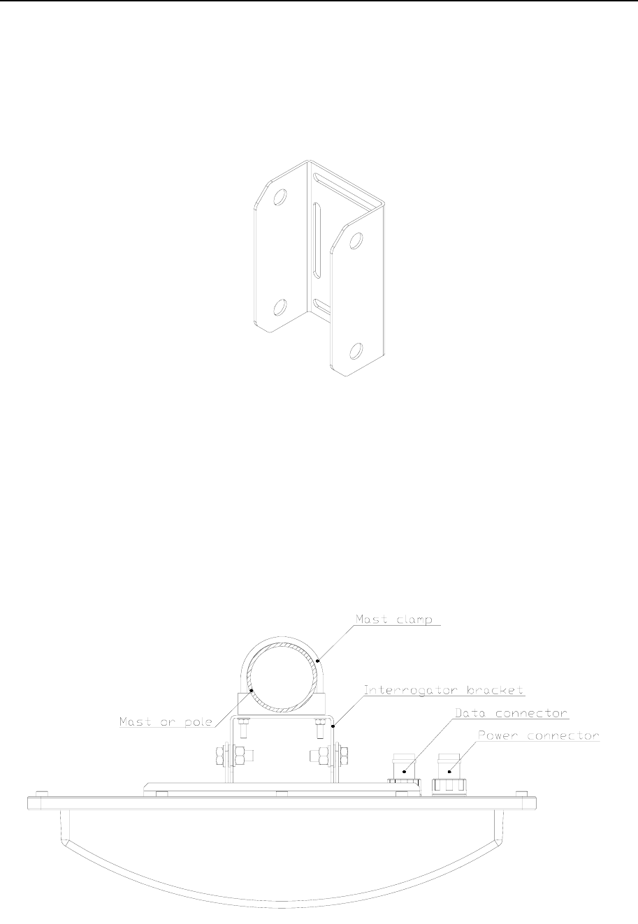
2. When the best mounting location for the Interrogator Unit has been identified, mount the
bracket to a mast, pole or rail with clamps as shown in Figure 6 and Figure 7. The
mounting plate is designed for 2-inch mast, pole or rail mounting and clamps are enclosed
with the delivery. The bracket can also be mounted on a wall. If wall mounted, remember
to make holes in the wall for entering the power and data cables to the connector at the
rear of the Interrogator Unit.
Figure 6 Interrogator Unit mounted to mast or pole, top view
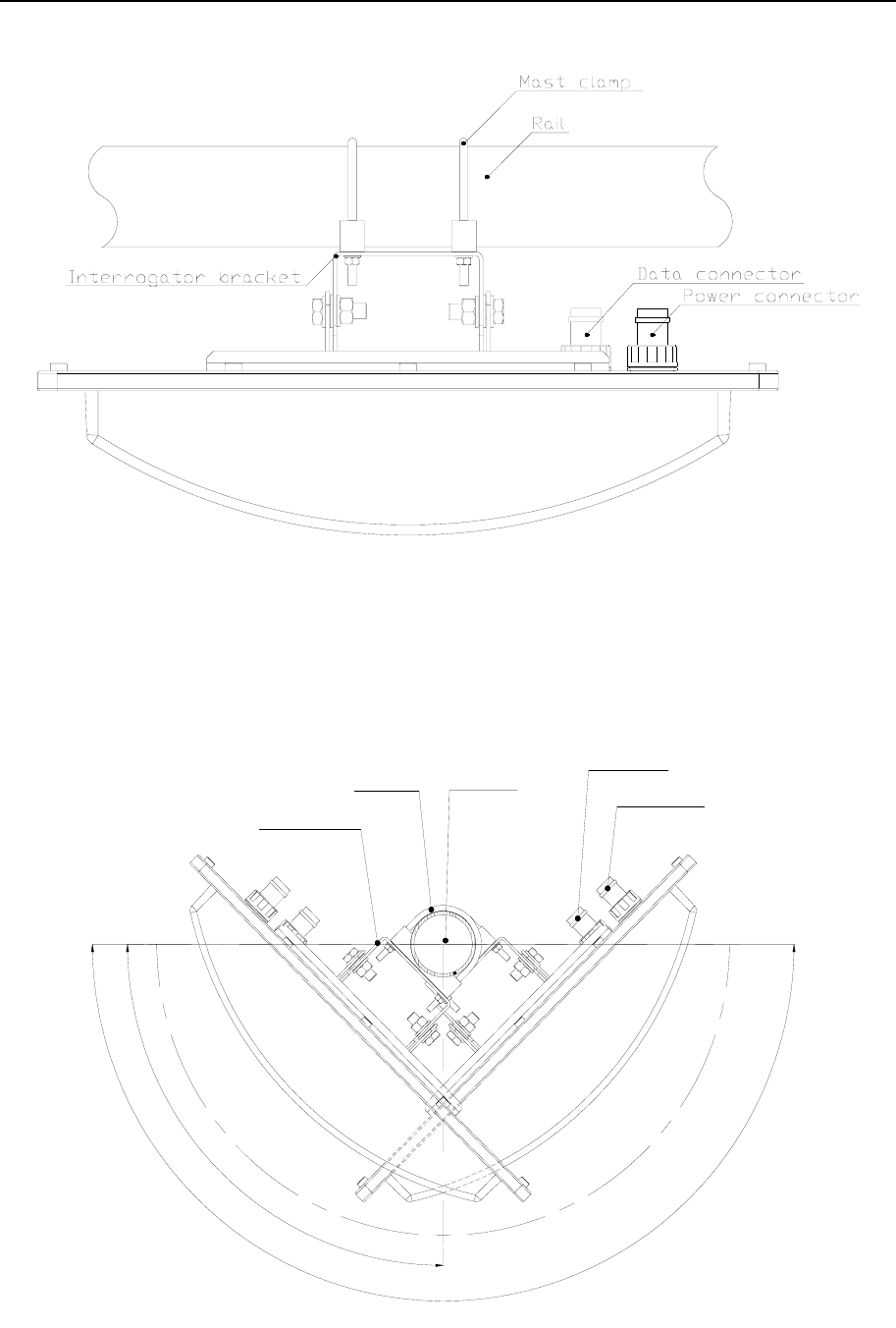
RADius 1000 Installation Manual, rev. 5 Installation
17
Figure 7 Interrogator Unit mounted to rail, top view
3. A typical dual Interrogator solution that will cover a 180 degree sector, is shown in Figure
8. Dual Interrogator mounting is done similar to single Interrogator solutions.
Power connector
Data connector
Interrogator bracket
Mast clamp Mast or pole
90°
180°
Figure 8 Dual Interrogator Unit mounted to mast or pole, top view
RADius 1000 Installation Manual, rev. 5 Installation
18
Note! Interrogators do not have to be mounted at the same location, but could be
displaced from each other.
4. Mount the base plate bracket at the rear of the Interrogator Unit to the mounting bracket
and insert the four screws. Secure the screws with the provided washers and self-locking
nuts.
Note! The longest Interrogator axis must be horizontally oriented, or else the RADius
system will not be able to track any transponders.
3.4.1.2 Transponder installation procedure
The Transponder is delivered with a mounting plate for mast, pole or rail installation. The
mounting plate is designed for 2-inch mast, pole or rail mounting and clamps are enclosed
with the delivery. The Transponder mounting plate can also be mounted directly on a wall or
on another foundation. The installation of the Transponder is performed in the following
steps:
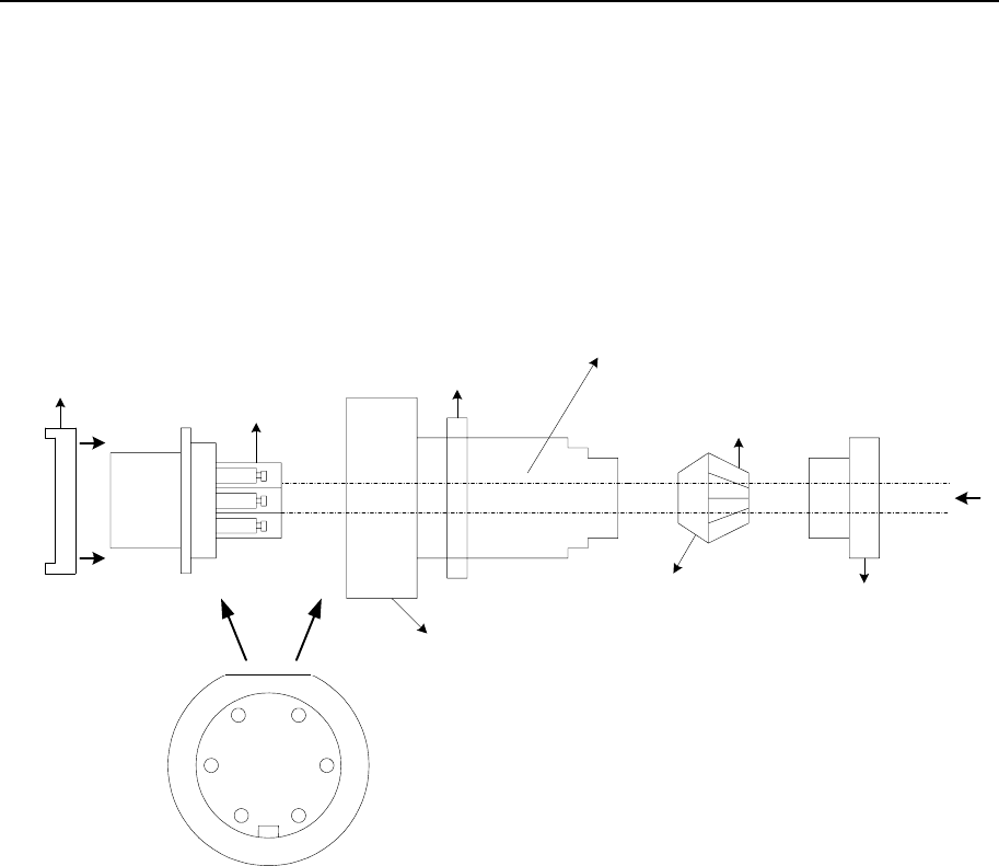
1. For installation of the Transponder in a mast, pole or to a rail use the enclosed clamps as
shown in Figure 9. Fasten the unit to a mast, pole or rail using the enclosed 2-inch clamps.
If wall mounted, remember to make a hole in the wall for entering the power cable to the
connector at the rear of the Transponder.
65
49
Power connector
Transponder bracket Transponder housing
Figure 9 Transponder, rear and side view
Caution! The longest Transponder axis must be horizontally oriented, or else the
RADius system will not be able to track the transponders.

RADius 1000 Installation Manual, rev. 5 Installation
19
3.4.1.3 Transponder Power Supply installation procedure
The Transponder Power Supply must be securely mounted.
Note! See References [3] and [4] for the installation of EX approved transponders.
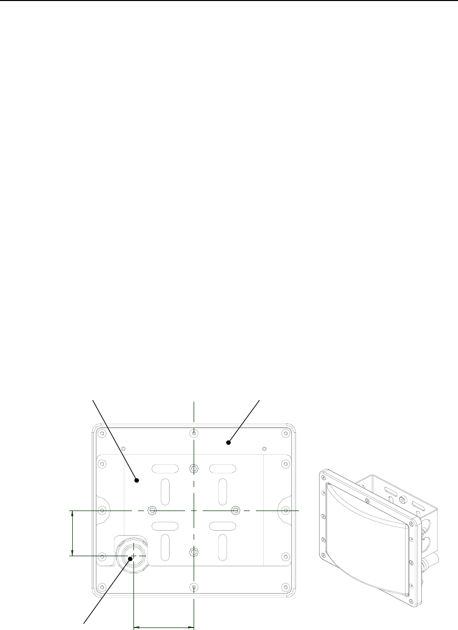
3.4.1.4 Controller Unit installation procedure
The cabinet must be securely mounted. Drilling plan for the resilient mounting is included in
the attached drawing 3840-MD-041 on page 33.
Caution! The power to the cabinet must be connected to a grounded mains outlet. This
applies to both the Processing Unit and Power Connection Shelf.
3.4.1.5 VDU installation procedure
Connect the VDU to the location labelled VGA at the rear panel of the Processing Unit.
3.4.2 Electrical installation
The electrical installation consists of:
• Connecting a power cable between the Interrogator Unit and the 48 VDC power located
on the Power/Connection Shelf.
• Connecting the data cable between the Interrogator Unit and Data/LAN connector on the
Power/Connection Shelf.
• Connecting cables with output data between the Processing Unit and external equipment
(optional).
• Connecting the Video Display Unit and the keyboard to the Processing Unit (optional).
• Supplying 110/230 VAC power to the Processing Unit and the Video Display Unit.
• Connecting 110/230VAC to the Power/Connection Shelf.
• Connecting a power cable between the Transponder and the Transponder power supply.
RADius 1000 Installation Manual, rev. 5 Installation
20
NET
MOUSE
KEYB
VGA
PPS
AUX - Serial
LPT1
MRU
grounded outlet only
Compass safe distance:
Steering Magnetic Compass : 1.1 m
Standard Compass : 1.9 m
: 100-240VAC/47-63Hz/100VA
: Must be connected to
: 2A
Input
Fuse
Class1
COM 6
COM 7 COM 10
COM 9
COM 2 COM 5 COM 8
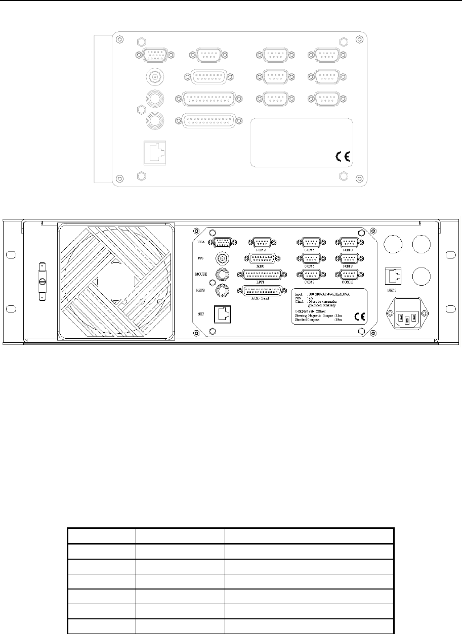
Figure 10 Rear panel of the Processing Unit
3.4.2.1 External output serial lines
RADius communicates with external equipment through RS-232 and RS-422 serial lines.
Output data are distance and bearing to dynamic positioning systems etc., hereafter called
host systems. No hardware or software handshake is used on the serial lines.
The configuration of serial lines and their default settings are:
Line Type Data
com5 RS-232 User configurable output
com6 RS-232 User configurable output
com7 RS-422 User configurable output
com8 RS-422 User configurable output
com9 RS-422 User configurable output
com10 RS-422 User configurable output
RADius 1000 Installation Manual, rev. 5 Installation
21
The connectors on the Processing Unit for the serial lines are of DB-9 male type. Pin layout:
RS-232 RS-422
Pin no. Signal Pin no. Signal
1 N/C 1 N/C
2 RXD 2 RX+
3 TXD 3 TX+
4 N/C 4 N/C
5 REF 5 REF
6 N/C 6 N/C
7 RTS 7 TX-
8 CTS 8 RX-
9 N/C 9 N/C
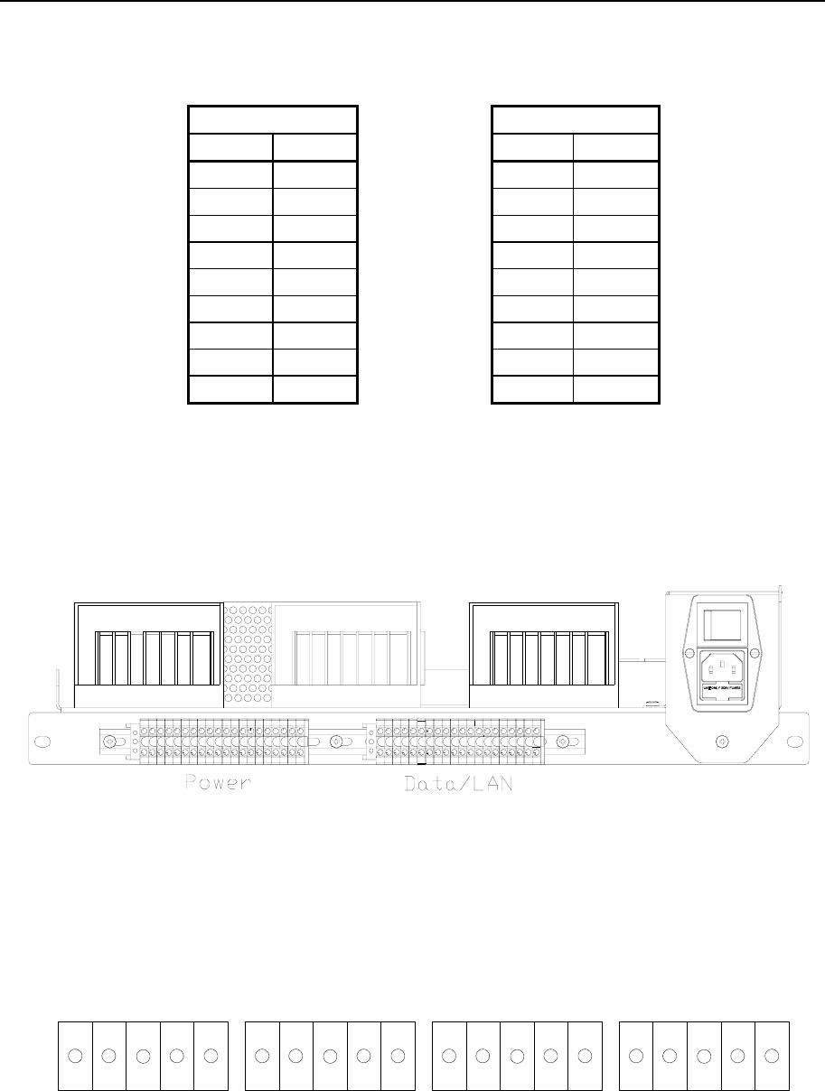
3.4.2.2 Power/Connection Shelf
Figure 11 shows the rear panel of the Power/Connection Shelf indicating the terminal rail for
power connection and for Data/LAN.
Figure 11 Power and Data/LAN terminal rails for the Interrogator cables
Figure 12 and Figure 13 illustrate the pin-out for the terminal rail Power and Data/LAN. In
the terminal rail connections for up to four Interrogator Units are included. Connection of
more than one Interrogator Unit is a future optional feature.
++ -
Shield
-++-
Shield
-++-
Shield
-++-
Shield
-
Interrogator 1 Interrogator 2 Interrogator 3 Interrogator 4
Pair 1 Pair 2 Pair 1 Pair 2 Pair 1 Pair 2 Pair 1 Pair 2
12345 678910 1112131415 1617181920
Figure 12 Pin numbers on Power terminal rail
RADius 1000 Installation Manual, rev. 5 Installation
22
Interrogator 1 Interrogator 2 Interrogator 3 Interrogator 4
TX+ TX- RX+ RX- Shield
Pair 1 Pair 2
TX+ TX- RX+ RX- Shield
Pair 1 Pair 2
TX+ TX- RX+ RX- Shield
Pair 1 Pair 2
TX+ TX- RX+ RX- Shield
Pair 1 Pair 2
1 2 3 4 5 6 7 8 9 10 11 12 13 14 15 16 17 18 19 20
Figure 13 Pin numbers on Data/LAN terminal rail
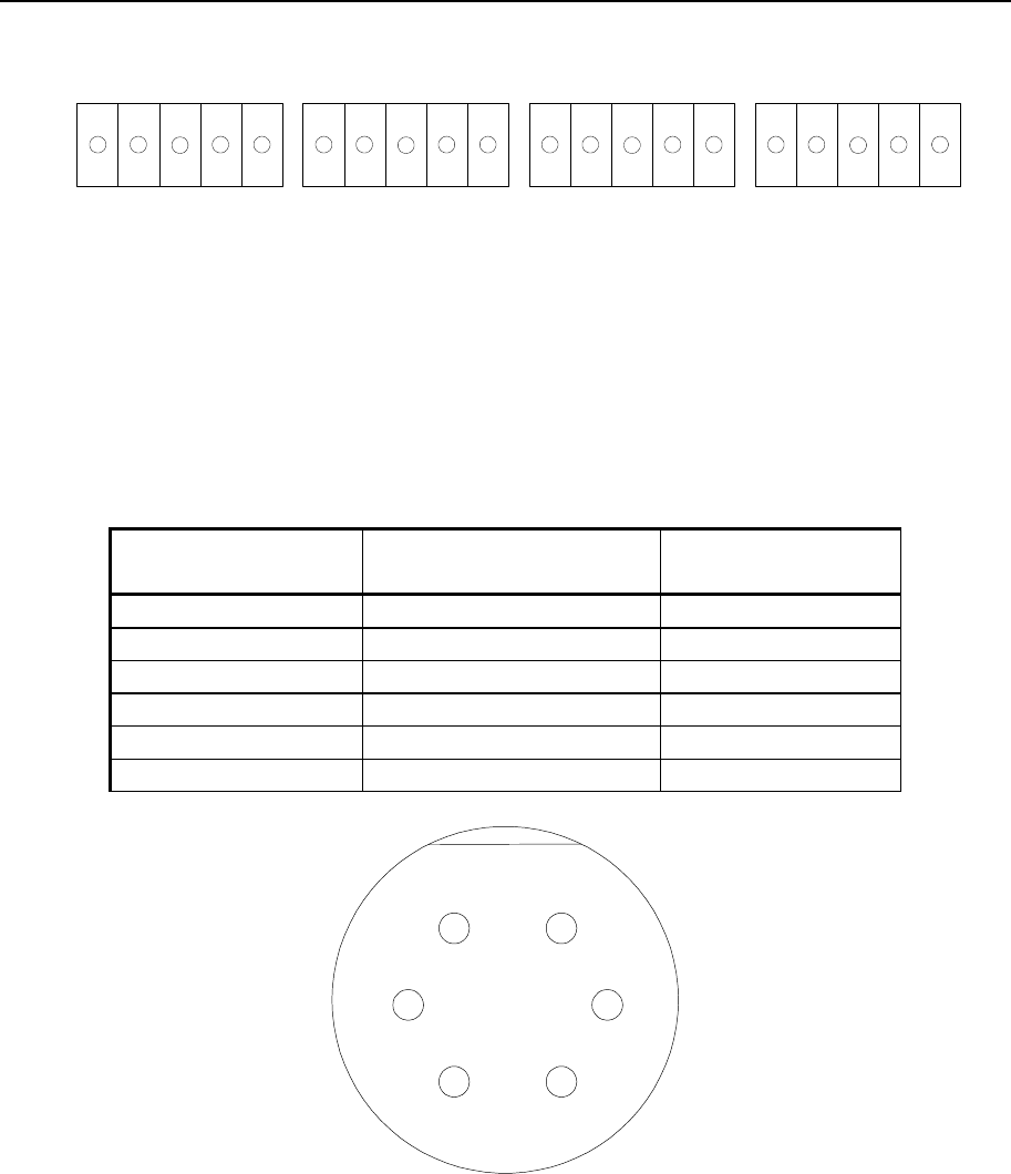
3.4.2.3 Interrogator data cable wiring
The data cable from the Interrogator Unit to the terminal rail on the Power/Connection Shelf
has the following cable wiring:
Signal Interrogator connector Data/LAN
Description Pin no. Pin no.
Shield wire 1 (5)
Data TX+ 2 1
Data TX- 3 2
NC 4
Data RX+ 5 3
Data RX- 6 4
1
4
6
3
52
Figure 14 Inside view of data communication connector on the Interrogator Unit cable
The connector used on the Interrogator Unit for data communication is of type Bulgin
Buccaneer standard 6-pole. The part number for the connector on the cable is PX0739/S. This
connector is a screw terminal type. For a description of the connector assembling, see
APPENDIX C - Bulgin connector assembly.
Note! After fastening the wires in the connector, use Loctite on the screw terminals to
avoid loosening of wires due to vibration. Also make sure that no Loctite is spilled
on the wires or in the wire mounting holes!
RADius 1000 Installation Manual, rev. 5 Installation
23
DataPower
Figure 15 Location of the data and power connectors on the Interrogator rear panel
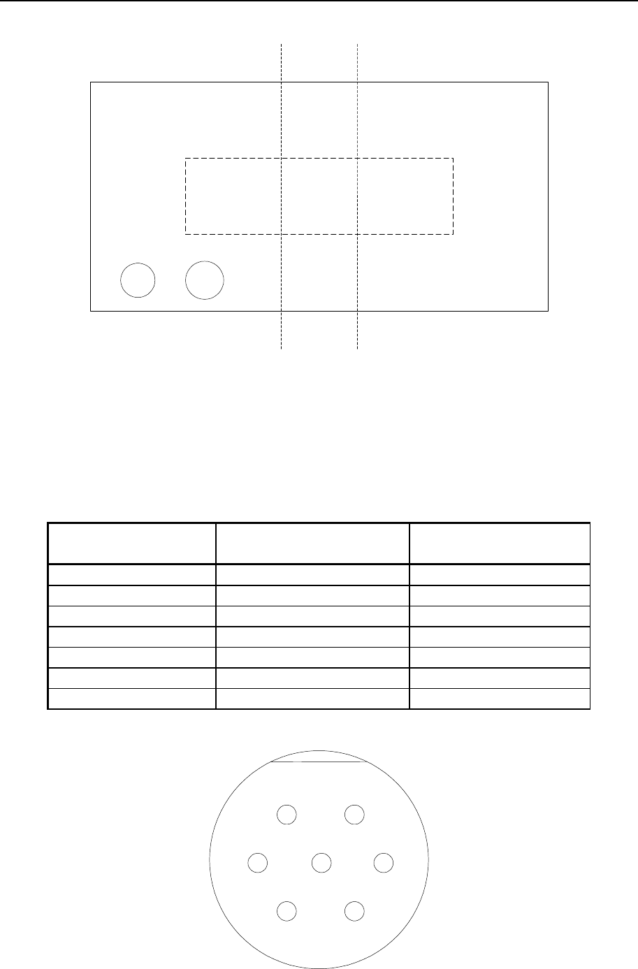
3.4.2.4 Interrogator power cable wiring
The power cable from the Interrogator Unit to the terminal rail on the Power/Connection
Shelf has the following cable wiring:
Signal Interrogator connector Power/Connection shelf
Description Pin no. Pin no.
Shield wire 1
GND (pair 1) 2 3
GND (pair 1) 3 4
+48 VDC (pair 2) 4 1
NC 5
NC 6
+48 VDC (pair 2) 7 2
1
4
6
3
52
7
Figure 16 Inside view of power connector used on the Interrogator Unit cable
RADius 1000 Installation Manual, rev. 5 Installation
24
The power connector used on the Interrogator is of type Bulgin Buccaneer standard 7-pole.
The part number for the connector on the cable is PX0745/S. This connector is a screw
terminal type. For a description of the connector assembling, see APPENDIX C - Bulgin
connector assembly.
Note! After fastening the wires in the connector, use Loctite on the screw terminals to
avoid loosening of wires due to vibration. Also make sure that no Loctite is spilled
on the wires or in the wire mounting holes!
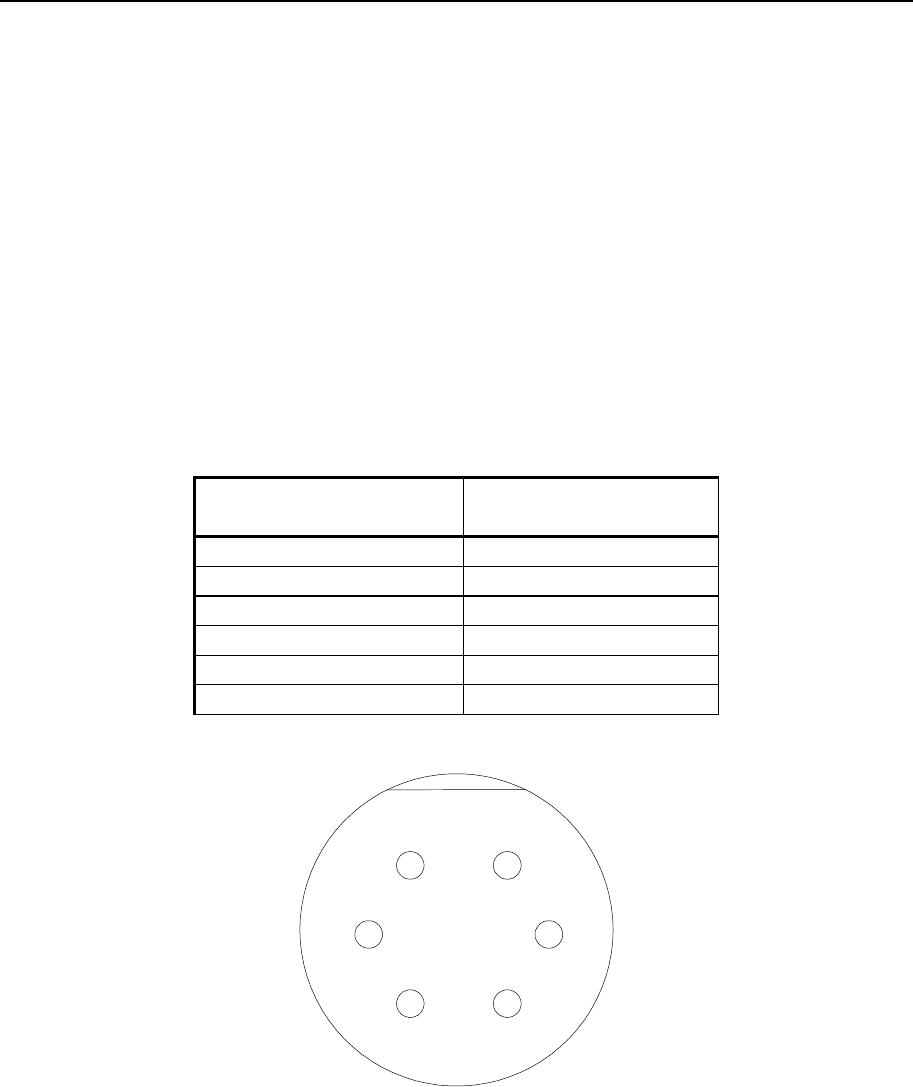
3.4.2.5 High Gain Transponder power cable wiring and installation
The cable wiring for the Transponder power cable is as follows:
Signal Connector
Description Pin no.
Shield 1
+ 6 VDC (pair 1) 2
+ 6 VDC (pair 1) 3
NC 4
GND (pair 2) 5
GND (pair 2) 6
1
4
6
3
52
Figure 17 Inside view of power connector on the Transponder cable
The power connector on the high gain Transponder is Bulgin 6-pole Buccaneer standard. The
part number for the connector on the cable is PX0739/S. This connector is a screw terminal
type. For a description of the connector assembling, see APPENDIX C - Bulgin connector
assembly.
Note! After fastening the wires in the connector, use Loctite on the screw terminals to
avoid loosening of wires due to vibration. Also make sure that no Loctite is spilled
on the wires or in the wire mounting holes!
RADius 1000 Installation Manual, rev. 5 Installation
25
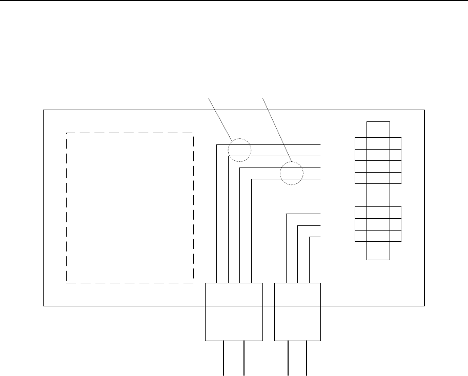
For the cable connections in the Transponder Power Supply, see the figure below. The cable
marked DC is the cable to the Transponder and the cable marked AC is the VAC input. The
shield wire to the Transponder is not connected in the Transponder Power Supply.
G
N
L
+6 V
+6 V
0 V
0 V
7
6
5
4
3
2
1
DC AC
Pair 1 Pair 2
Figure 18 Transponder Power Supply cable connections
WARNING! The power to the Transponder Power Supply is Class 1
equipment and must be properly connected to a grounded
mains outlet!
3.4.2.6 Low Power Transponder battery switch
Please note that the RADius 500 Transponder needs an LP-Transponder activate switch
installed in the connector position on the rear side for applying the battery power.
WARNING! NEVER connect other equipment than the supplied battery
switch to the rear connector. An attempt to connect other
sources to the connector pins may cause a hazard.
3.4.2.7 Interrogator Cable installation procedure
1. Connect the power cable connector to the rear of the Interrogator Unit and the other end
of the cable to the Power terminal list on the Power/Connection Shelf. Shields shall be
connected in the provided terminals. The shield terminals on the connection shelf are
floating. Shields are terminated inside the Interrogator Unit.

RADius 1000 Installation Manual, rev. 5 Installation
26
Use the required number of clips to fasten the cable to the mast, pole, rail or wall.
2. Connect the data cable connector to the rear of the Interrogator Unit and the other end of
the cable to the Data/LAN terminal list on the Power/Connection Shelf. Shields shall be
connected in the provided terminals. The shield terminals on the connection shelf are
floating. Shields are terminated inside the Interrogator Unit.
Use the required number of clips to fasten the cable to the mast, pole, rail or wall.
3. Connect the cables for output data from the Processing Unit to external equipment to the
ports com5, 6, 7 or com8 for serial communication. These are located on the rear panel of
the Processing Unit. An Ethernet connector (NET 2) is also available for future use.
4. Connect the 110/230V AC ship's power supply to the power connector at the rear of the
Power/Connection Shelf.
5. Connect the cable from the Video Display Unit and the keyboard to the corresponding
connectors at the rear of the Processing Unit.
6. Connect the Video Display Unit to 110/230V AC ship's power.
7. Connect the power cable connector to the rear of the Transponder and the other end of the
cable to the Transponder power supply. Use the required number of clips to fasten the
cable to the mast, pole, rail or wall.
8. When all cables are connected, power on the Processing Unit. The four LED indicators
located on the front panel of the Processing Unit blink red shortly before the left LED
turns green, indicating that the Processing Unit is powered and operational.
RADius 1000
LEDs
Figure 19 Processing Unit front view showing status LEDs
RADius 1000 Installation Manual, rev. 5 Installation
27
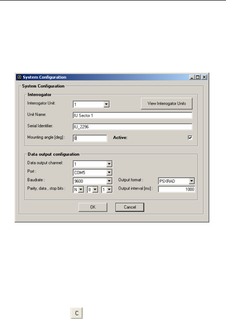
3.4.3 Setup of configuration parameters
Configuration parameter setup consists of:
• Select Interrogator Unit (see chapter 3.4.3.1)
• Entering the mounting angle for the Interrogator Unit (see chapter 3.4.3.2)
• Entering output data interface (see chapter 3.4.3.3)
Figure 20 System Configuration dialog box
Always fill in the setup parameters for the specific installation in the Installation Worksheet
before entering the setup software. Fill in the parameters directly in the worksheet found in
the Appendix A - Installation worksheet in the manual. In this way, the parameters for the
actual installation will be easier to find when requested later.
3.4.3.1 Select Interrogator Unit
During first boot after installation, it is necessary to select which Interrogator Unit to use.
This is done by selecting the button in the Radius GUI. This will open the window
shown in Figure 20. By selecting View Interrogator Units, a list of current Interrogators
appears (as in Figure 21).
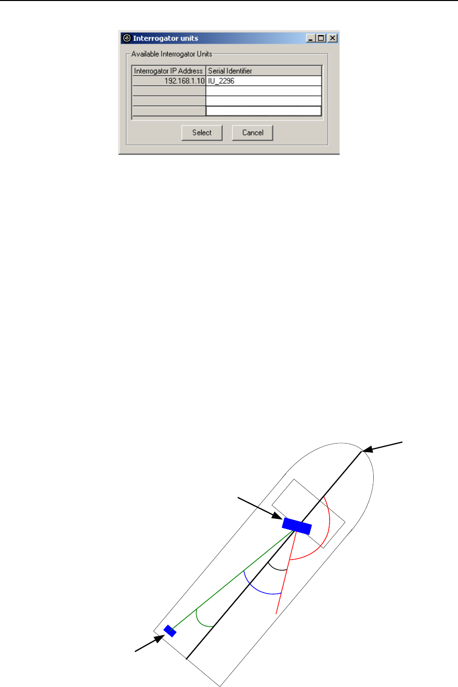
RADius 1000 Installation Manual, rev. 5 Installation
28
Figure 21 View Interrogator Units menu
For each Interrogator Unit edit the Unit Name, shown in Figure 20, to identify the
Interrogators after installation (e.g. IU 1 Port side). When choosing between different
Interrogators at the installation, select the Interrogator Unit drop down menu. Then choose
which Interrogator to use, and make sure that the Active check box is checked (as shown in
Figure 20).
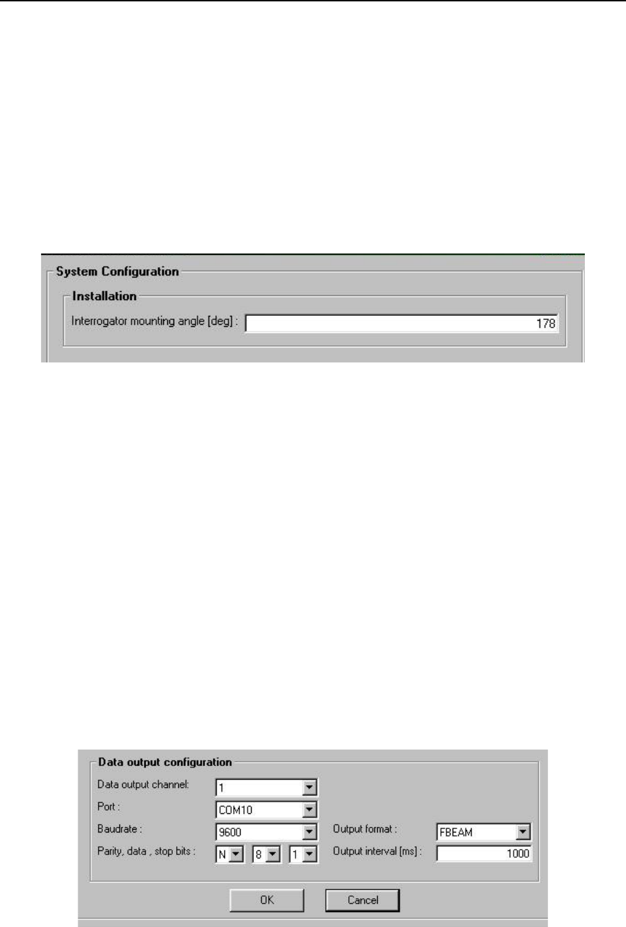
3.4.3.2 Interrogator mounting angle
The Interrogator's mounting angle has to be calibrated after installation. RADius outputs
direction to the Transponder relative to the vessel's centre line (0 forward, positive to
starboard). The Interrogator is typically pointing backwards on the vessel. If the mounting
angle had been 180 degrees, then the mounting angle in the system configuration box above
should have been 180 degrees. However, the actual installation angle is seldom met exactly
and a procedure to measure the actual angle is shown in Figure 22.
Figure 22 Measuring the mounting angle for the Interrogator
α1
α
2
Expected angle = α
1
Measured angle = α
2
Offset = α
3
Orientation angle = α
4
α3
α4
Centre line
ship
Interrogator
Transponder
α4= 180 - α
3
α3
= α
2
- α
1
RADius 1000 Installation Manual, rev. 5 Installation
29
In this example the Transponder is mounted at the stern of the vessel.
1. The location of the Transponder is measured relative to the centre line of the vessel and
the Expected angle , α1, is calculated.
2. The system measures the angle to the Transponder, Measured angle: α2, and the offset
from the expected angle, Offset angle: α3, is computed.
3. Then the Mounting angle, α4, can be computed based on the expected mounting angle
(180° in the example above) and the computed installation Offset angle, α3.
Figure 23 Interrogator mounting angle
3.4.3.3 Data output
The Processing Unit has to be set up to output data to a DP system, following the procedure
below:
1. Select which data output channel that is to be configured. This is usually channel 1.
2. Select which port that is going to be used.
3. Configure the port settings according to the settings on the host system.
4. Select the wanted output format. PSXRAD, FBEAM, ARTEMIS and ABB DP are
available. For a description of the different formats, see Appendix B - Output Protocols.
5. Set the wanted output interval [ms]. The default value is 1000. This gives an output
frequency of 1 Hz (one telegram per second).
Figure 24 Data output configuration

RADius 1000 Installation Manual, rev. 5 Installation
30
Blank page

RADius 1000 Installation Manual, rev. 5 Installation drawings
31
4. INSTALLATION DRAWINGS
This chapter contains the outline drawings showing the mechanical dimensions of the
Processing Unit, the Interrogator Unit and the Transponder.
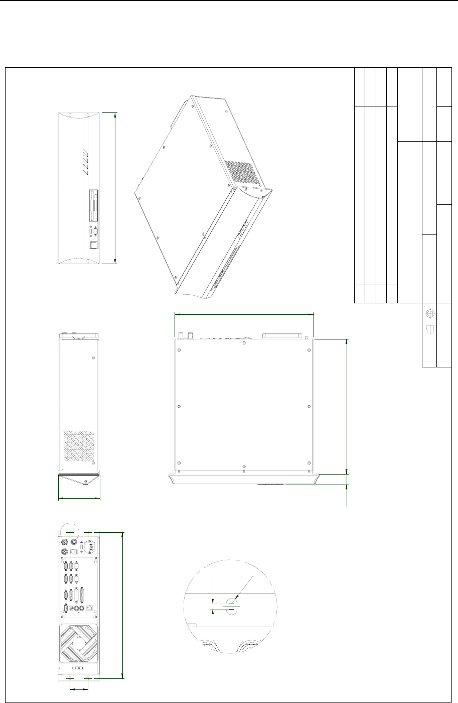
RADius 1000 Installation Manual, rev. 5 Installation drawings
32
4.1 RADius Processing Unit, dimensions
Approved :
Checked :
Subtitle:
Title :
Issued :
Drawing no:
Xref file :
Projection:
Rev. Description
Date:
Date, Sign.
Design by :
Usage:
Rev. no: Scale :
31438-MA-010
HW PLATTFORM
1:5
KL
99.05.03 04.11.25 4
Standard enclosure for mounting in 19" racks.
Basic material Aluminium.
Fits into slots with height 3 Units. ( 1U = 44.45mm )
ENCLOSURE DIMENSIONS
KONGSBERG
SEATEX
Assey
443
430
33,6
465
57,1
132,5 (3U)
482
DETAIL A
3,5
R3,5
A
RADius 1000 Installation Manual, rev. 5 Installation drawings
33
4.2 RADius Controller Unit, dimensions
Rev. Description Date, Sign.
R AD i us 1000
SEATEX
KONGSBERG
RADius 1000 Installation Manual, rev. 5 Installation drawings
34
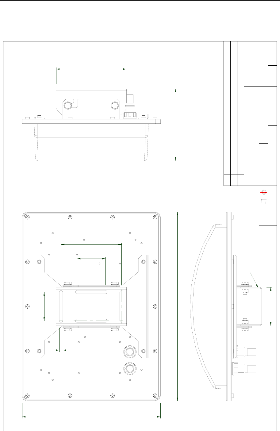
4.3 RADius Interrogator, dimensions
Approved :
Checked :
Subtitle:
Title :
Issued :
Drawing no:
Xref file :
Projection:
Rev. Description
Date:
Date, Sign.
Design by :
Usage:
Rev. no: Scale :
3
KL
KONGSBERG
SEATEX
INTERROGATOR DIMENSIONS
RADIUS
05.01.31 Not to scale
External
04.03.16
3840-MA-011
Bracket material : El.zn Steel, powder coated
Housing material : Aluminium
Cover : Plastic
Interogator Bracket
114
412
210
214
562
85
180
85
10 Typ.
RADius 1000 Installation Manual, rev. 5 Installation drawings
35
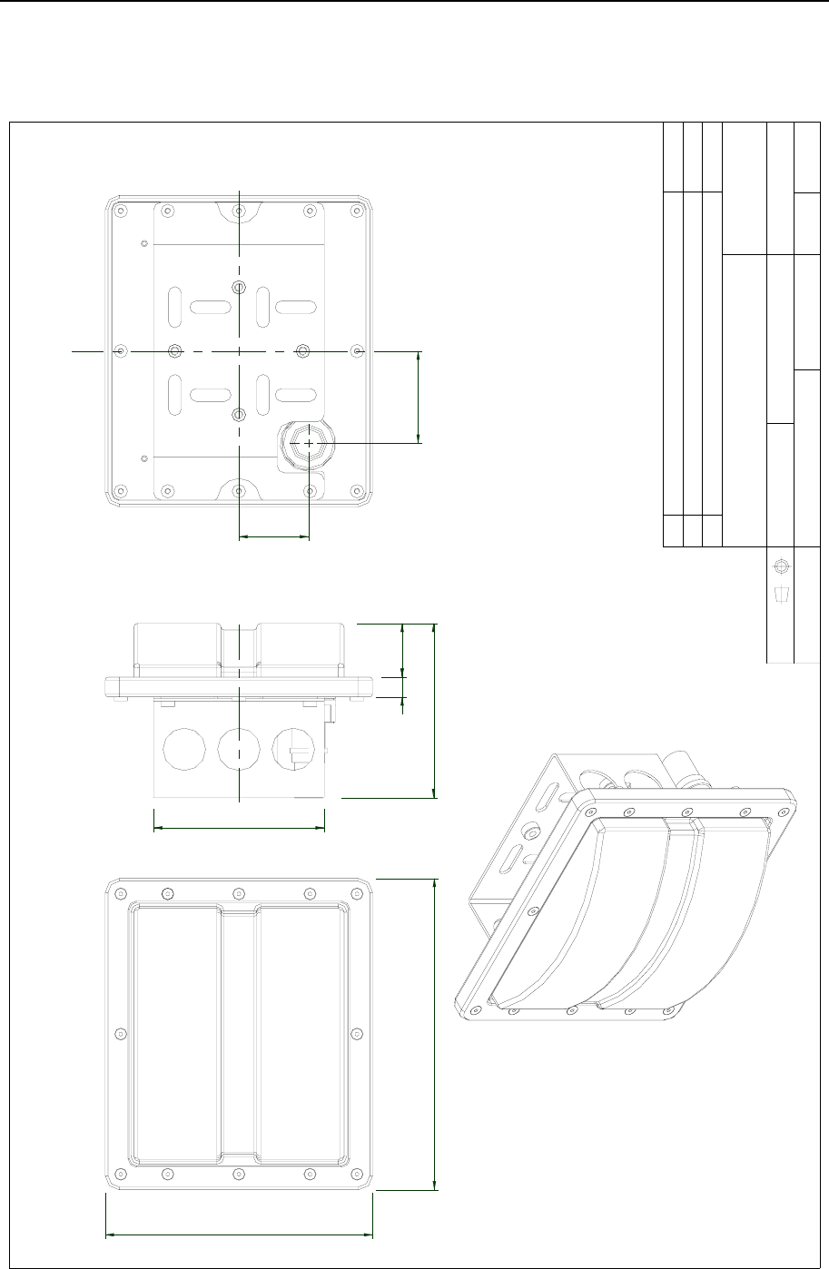
4.4 RADius Transponder 500 Low Power, dimensions
Approved :
Checked :
Subtitle:
Title :
Issued :
Drawing no:
Xref file :
Projection:
Rev. Description
Date:
Date, Sign.
Design by :
Usage:
Rev. no: Scale :
1
KL
KONGSBERG
SEATEX
3840-MA-020 External
Not to scale
RADIUS
TRANSPONDER DIMENSIONS
Bracket material : Stainless Steel AISI 316
Housing material : Aluminium
Cover : Plastic
04.08.12
04.03.15
188
220
3814
123
65
49
120
RADius 1000 Installation Manual, rev. 5 Installation drawings
36
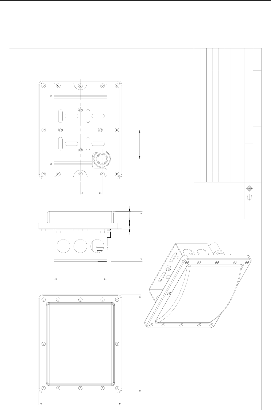
4.5 RADius Transponder 600 High Gain, dimensions
Approved :
Checked :
Subtitle:
Title :
Issued :
Drawing no:
Xref file :
Projection:
Rev. Description
Date:
Date, Sign.
Design by :
Usage:
Rev. no: Scale :
Description
Tolerance: ISO 2768-M if not specified on drawing
Material
KL
KONGSBERG
SEATEX
Detail
Bracket material : Stainless Steel AISI 316
Housing material : Aluminium
Cover : Plastic ABS/PMMA
TRANSPONDER DIMENSIONS
RADius 600 HIGH GAIN
06.11.27 006.11.27
Not to scale
3840-MA-026
220
188
112
120
14 26
65
49

RADius 1000 Installation Manual, rev. 5 Parts list
37
5. PARTS LIST
The RADius 1000 system consists of:
Part no. No. Description
RAD-S-SIN_00 RADius 1000 Single Interrogator
RAD-E-IU_00 1 RADius 1000 Interrogator Unit
RAD-E-PU_00 1 RADius 1000 Processing Unit
RAD-M-IUB_00 1 RADius Mounting Bracket Interrogator
RAD-E-PS1_00 1 RADius Power/Connection Shelf Single Interrogator
RAD-C-CAB_00 1 RADius IU & Transp. Cable
RAD-C-IUP_00 1 RADius Power Connector Interrogator 7 pole
RAD-C-IUN_00 1 RADius Net Connector Interrogator 6 pole
RAD-S-LPT_00 1 RADius 500 Low Power Transponder, including LP-
transponder activate switch
G071-21 1 Cabinet, Height 6U
G060-31 1 VGA monitor, LCD, office type, 15", including G071-28
power cable 1.5 m
G071-27 1 Keyboard with rollerball, 19" rack mounted
RAD-D-USR_00 1 RADius User Manual
RAD-D-IST_00 1 RADius Installation Manual
RAD-S-HGT_00 RADius 600 High Gain Transponder
RAD-C-CAB_00 1 RADius IU & Transp. Cable
RAD-E-HGT_00 1 RADius 600 High Gain Transponder
RAD-E-TPS_00 1 RADius Power Supply Transponder
RAD-C-TRP_00 1 RADius Power Conn. High Gain Transponder
RAD-M-TBW_00 1 RADius Mounting Bracket Wall Transponder
RAD-M-TBM_00 1 RADius Mounting Kit Mast Transponder
RAD-S-LPT_00 RADius 500 Low Power Transponder
RAD-E-LPT_00 1 RADius 500 Low Power Transponder
RAD-M-TBM_00 1 RADius Mounting Kit Mast Transponder
RAD-M-TBW_00 1 RADius Mounting Bracket Wall Transponder

RADius 1000 Installation Manual, rev. 5 Parts list
38
RAD-S-DIN_00 RADius 1000 Dual Interrogator
RAD-E-IU_00 2 RADius 1000 Interrogator Unit
RAD-E-PU_00 1 RADius 1000 Processing Unit
RAD-M-IUB_00 2 RADius Mounting Bracket Interrogator
RAD-E-PS2_00 1 RADius Power/Connection Shelf Dual Interrogator
RAD-C-CAB_00 2 RADius IU & Transp. Cable
RAD-C-IUP_00 2 RADius Power Connector Interrogator 7 pole
RAD-C-IUN_00 2 RADius Net Connector Interrogator 6 pole
RAD-S-LPT_00 1 RADius 500 Low Power Transponder, including LP-
transponder activate switch
G071-21 1 Cabinet, Height 6U
RAD-M-ITB_00 1 RADius Mounting Bracket Twin Interrogator
RAD-M-TBW_00 1 RADius Mounting Bracket Wall Transponder
G060-31 1 VGA monitor, LCD, office type, 15", including G071-28
power cable 1.5 m
G071-27 1 Keyboard with rollerball, 19" rack mounted
RAD-D-USR_00 1 RADius User Manual
RAD-D-IST_00 1 RADius Installation Manual
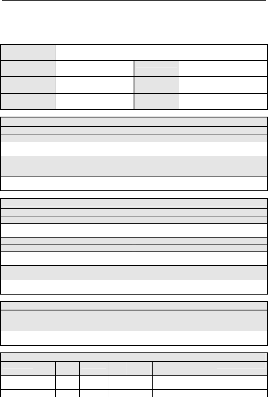
RADius 1000 Installation Manual, rev. 5 Appendix A - Installation worksheet
39
APPENDIX A - INSTALLATION WORKSHEET
Vessel
RADius serial no.
IU serial no.
Place
Date
Installed by
Signature
Vessel Geometry
Vessel Dimension:
Length [m] Width [m] Height [m]
Centre of Gravity (CG) Location:
From CG to AP (Aft Point) [m]
(positive forward of CG)
From CG to CL (Centre Line) [m]
(positive to starboard of CG)
From CG to the Keel [m]
(positive below CG)
Vessel Description
Vessel Data:
Vessel Type and Name Vessel Owner Country of Origin
Management:
Manager Phone Number
RADius:
RADius Owner RADius Manager
Interrogator Mounting Angle
Heading offset
(Reference - Interrogator reading)
[deg]
Reference [deg] Interrogator [deg]]
Data Output – Digital RS-232/422 Output Configuration
Device Line
(com)
Electric
232/422
Baud rate Parity
(st. n)
Data bits
(st. 8)
Stop bits
(st.1)
Interval
[s]
Format
Out Port #1

RADius 1000 Installation Manual, rev. 5 Appendix A - Installation worksheet
40
Blank page

RADius 1000 Installation Manual, rev. 5 Appendix B – Output Protocols
41
APPENDIX B - OUTPUT PROTOCOLS
The available output data formats are as follows:
Name Format no. Description
PSXRAD 1 NMEA proprietary messages
Fanbeam BCD telegram 2 Fanbeam binary format
ARTEMIS 3 Pseudo Artemis, ASCII 17 bytes format
ABB DP 4 Pseudo Fanbeam, ASCII 333 bytes adapted for ABB DP.
5.1 PSXRAD, NMEA proprietary format
The NMEA format is an ASCII text format based on the NMEA 0183 standard defined in [1].
RADius utilises the proprietary PSXRAD format described below.
Format:
Note that this telegram is repeated for every Transponder tracked. The field marked ss is a
sequence number indicating what telegram this is of a total of the number of transponders
initiated for tracking (indicated by field nn).
$PSXRAD,I,hhmmss.ss,nn,ss,tid,rrrr.rr,aa.a,bbb.bb,ss.s,±vv.vv,ff.f,±
dd.dd,sn,S*cc<cr><lf>
I ID for Interrogator, range 0-9
hhmmss.ss Time of position hour, minutes, seconds
nn Number of transponders set up for tracking, range 0 – 99
ss Sequence number (multiple transponders), range 0 – (nn-1)
tid Transponder ID, the number is the transponder frequency in 10KHz resolution.
150 is then 1.5 MHz transponder
rrrr.rr Range in meters, decimal centimetres
aa.a Range accuracy estimate (1 σ level in m)
bbb.bb Bearing to transponder 0.00 to 360.00 degrees
ss.s Bearing accuracy estimate (1 σ level in deg)
±vv.vv Vertical angle to transponder (-90.0 - +90.0), the + sign is omitted when
positive.
ff.f Vertical angle accuracy estimate (1 σ level in deg)
±dd.dd Velocity relative to transponder (doppler) m/s, the + sign is omitted when
positive.
sn Signal to noise in DB 0 – 90, less than10 is not good, 10 – 15 is week, > 15 is
good
S Status 0 – 9 (0 – No reply (not tracking transponder), 1 – Other error, do not
use, 2 – Range only, 3 – 8 TBD, 9 – Valid Status)
*cc Computed checksum
<cr> Carriage Return
<lf> Line Feed
The telegram above is repeated for all Interrogators installed in the RADius system

RADius 1000 Installation Manual, rev. 5 Appendix B – Output Protocols
42
5.2 Fanbeam BCD telegram
This telegram supports one Transponder only. This Transponder output can be selected from
the RADius GUI.
BBBRRR00T
where:
BBB is the bearing in packed BCD format.
RRR is the range in packed BCD format.
00 are two ASCII zero bytes.
T is the ASCII character 255 acting as the terminator.
Byte 1 : ab bearing = abc.def deg.
Byte 2 : cd
Byte 3 : ef
Byte 4 : gh range = ghijk.l meter
Byte 5 : ij
Byte 6 : kl
Byte 7 : 0
Byte 8 : 0
Byte 9 : 0xFF

RADius 1000 Installation Manual, rev. 5 Appendix B – Output Protocols
43
5.3 Pseudo Artemis telegram
This telegram supports one Transponder only. This Transponder output can be selected from
the RADius GUI.
ABCDEF GHIJKL S[CR][LF]
Where:
ABCDEF is the range in decimeter, ASCII, ABCDE.F (m)
GHIJKL is the bearing in degrees, ASCII, GHI.JKL (deg).
S Status, '0' (0x30) is invalid data. '1' (0x31) is valid data
Byte 1-6 : abcdef, Range in decimeter (abcde.f m).
Byte 7 : Space
Byte 8-13 : ghijkl, Bearing in degrees (ghi.jkl deg).
Byte 14 : Space
Byte 15 : s, Status flag, '0' (0x30) is invalid data, '1' (0x31) is valid data.
Byte 16 : [CR], Carriage Return
Byte 17 : [LF], Line Feed
Note that this telegram differs from Artemis When it comes to bearing. Bearing in Artemis is
relative to North. Bearing from RADius is relative to vessels heading.

RADius 1000 Installation Manual, rev. 5 Appendix B – Output Protocols
44
5.4 ABB DP telegram
This telegram supports one Transponder only. This Transponder output can be selected from
the RADius GUI.
SN,RRRR.R,BBB.BB,TTT,S,HH:MM:SS[CR][LF]
Where:
SN Signal to Noise Ratio (dBm), ASCII
RRR.R Is the range in meters, ASCII
BBB.BB Bearing in degrees, ASCII
TTT Transponder ID, ASCII
S Status, ASCII, 0 – 9 (0 – No reply (not tracking transponder), 1 –
Other error, do not use, 2 – Range only, 3 – 8 TBD, 9 – Valid Status)
HH:MM:SS Time, ASCII, Hour : Minutes : Seconds from system time.
Byte 1-2 : SN.
Byte 3 : Comma Character
Byte 4-9 : RRR.R, Range (meters)
Byte 10 : Comma Character
Byte 11-16 : BBB.BB, Bearing (degrees)
Byte 17 : Comma Character
Byte 18-20 : TTT, Transponder ID (range 150 – 300)
Byte 21 : Comma Character
Byte 22 : Status, See above
Byte 23 : Comma Character
Byte 24-31 : Time
Byte 32 : [CR], Carriage Return
Byte 33 : [LF], Line Feed
RADius 1000 Installation Manual, rev. 5 Appendix C - Bulgin connector assembly
45
APPENDIX C - BULGIN CONNECTOR
ASSEMBLY
It is very important that the Bulgin connector is correctly assembled to ensure that the
connectors are watertight. Follow the instructions below carefully.
Cable
Gland nut
Gland
Gland
cage
Sealing
cap clip
Screw
terminals
Locking
ring
Retaining
ring
Insert in correct position
PLEASE NOTE THAT THE FLAT PART OF THE
SCREW TERMINAL MUST MATCH THE
CORRESPONDING FLAT PART INSIDE THE
CONNECTOR MAIN BODY.
Connector
main body
Figure 25 Bulgin connector assembly
• The gland nut shown in the figure above should be replaced with the supplied gland nut
with strain relief.
• Insert the cable through the glands and the connector main body before connecting the
wires to the screw terminals.
Note! After fastening the wires in the connector, use Loctite on the screw terminals to
avoid loosening of wires due to vibration.
When inserting the screw terminal part into the connector main body, be sure to rotate the part
until it is locked before installing the retaining ring. The flat part of the screw terminal must
match the corresponding flat part inside the connector main body. A good way to ensure a
correct installation is to rotate the screw terminal body inside the connector main body until it
locks and can not be rotated more.
It is in addition recommended to vulcanize all outdoor connectors with self vulcanizing tape.

RADius 1000 Installation Manual, rev. 5 Appendix C - Bulgin connector assembly
46
Caution! If the screw terminal body is not correctly mounted in the connector main
body, the assembled connector will not be waterproof.
It is recommended to use self vulcanizing tape on the assembled connector.
RADius 1000 Installation Manual, rev. 5 Appendix C - Bulgin connector assembly
47
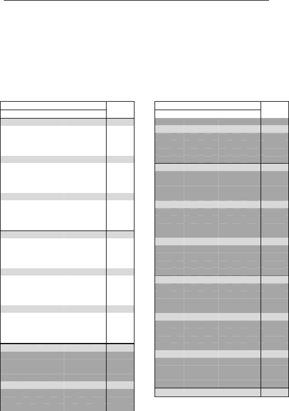
APPENDIX D - TRANSPONDER ID SETTINGS
The table below shows the possible DIP switch settings for setting the TID on the RADius
Transponders. Standard settings are 150, 160, 170 … up to 300. Note that the battery powered
RADius 500 Low Power Transponders has two jumpers close to the middle of the card that
has to be shifted from lower to upper position when the frequency identities is 210 or higher
(marked with different colour in the table).
Switch Setting TID
MSB LSB
0 0 0 0 0 0 0 150
0 0 0 0 0 0 1 152
0 0 0 0 0 1 0 154
0 0 0 0 0 1 1 156
0 0 0 0 1 0 0 158
0 0 0 0 1 0 1 160
0 0 0 0 1 1 0 162
0 0 0 0 1 1 1 164
0 0 0 1 0 0 0 166
0 0 0 1 0 0 1 168
0 0 0 1 0 1 0 170
0 0 0 1 0 1 1 172
0 0 0 1 1 0 0 174
0 0 0 1 1 0 1 176
0 0 0 1 1 1 0 178
0 0 0 1 1 1 1 180
0 0 1 0 0 0 0 182
0 0 1 0 0 0 1 184
0 0 1 0 0 1 0 186
0 0 1 0 0 1 1 188
0 0 1 0 1 0 0 190
0 0 1 0 1 0 1 192
0 0 1 0 1 1 0 194
0 0 1 0 1 1 1 196
0 0 1 1 0 0 0 198
0 0 1 1 0 0 1 200
0 0 1 1 0 1 0 202
0 0 1 1 0 1 1 204
0 0 1 1 1 0 0 206
0 0 1 1 1 0 1 208
0 0 1 1 1 1 0 210
0 0 1 1 1 1 1 212
0 1 0 0 0 0 0 214
0 1 0 0 0 0 1 216
0 1 0 0 0 1 0 218
0 1 0 0 0 1 1 220
0 1 0 0 1 0 0 222
0 1 0 0 1 0 1 224
0 1 0 0 1 1 0 226
Switch Setting TID
MSB LSB
0 1 0 0 1 1 1 228
0 1 0 1 0 0 0 230
0 1 0 1 0 0 1 232
0 1 0 1 0 1 0 234
0 1 0 1 0 1 1 236
0 1 0 1 1 0 0 238
0 1 0 1 1 0 1 240
0 1 0 1 1 1 0 242
0 1 0 1 1 1 1 244
0 1 1 0 0 0 0 246
0 1 1 0 0 0 1 248
0 1 1 0 0 1 0 250
0 1 1 0 0 1 1 252
0 1 1 0 1 0 0 254
0 1 1 0 1 0 1 256
0 1 1 0 1 1 0 258
0 1 1 0 1 1 1 260
0 1 1 1 0 0 0 262
0 1 1 1 0 0 1 264
0 1 1 1 0 1 0 266
0 1 1 1 0 1 1 268
0 1 1 1 1 0 0 270
0 1 1 1 1 0 1 272
0 1 1 1 1 1 0 274
0 1 1 1 1 1 1 276
1 0 0 0 0 0 0 278
1 0 0 0 0 0 1 280
1 0 0 0 0 1 0 282
1 0 0 0 0 1 1 284
1 0 0 0 1 0 0 286
1 0 0 0 1 0 1 288
1 0 0 0 1 1 0 290
1 0 0 0 1 1 1 292
1 0 0 1 0 0 0 294
1 0 0 1 0 0 1 296
1 0 0 1 0 1 0 298
1 0 0 1 0 1 1 300

RADius 1000 Installation Manual, rev. 5 Appendix C - Bulgin connector assembly
48
Blank page
RADius 1000 Installation Manual, rev. 5 Appendix E - Transportation
49
APPENDIX E - TRANSPORTATION
Information on transportation for RADius 500 containing lithium
battery
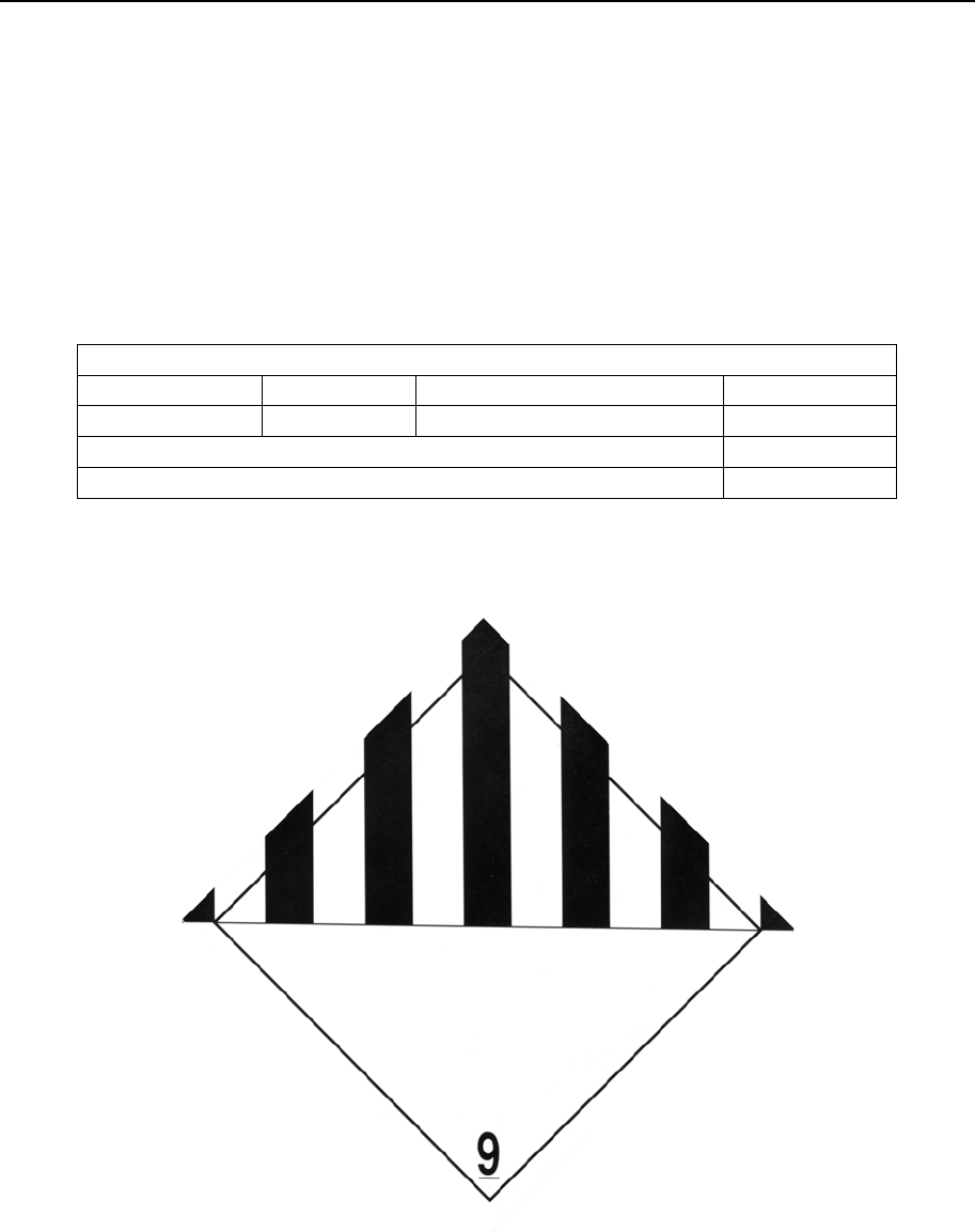
The RADius 500 packaging is labelled with the following:
LITHIUM BATTERIES CONTAINED IN EQUIPMENT
CLASS 9 UN 3091 NET WT OF LITHIUM 5 GRAMS
PACKING INSTRUCTIONS 912, II
In addition the symbol below is used:
Figure 26 Dangerous goods class 9 UN-3091

RADius 1000 Installation Manual, rev. 5 Appendix E - Transportation
50
Blank page

RADius 1000 Installation Manual, rev. 5 Index
51
Index
B
battery, 11
battery switch, 26
Bulgin connector, 45
C
cable, 8
cable resistance, 14
connector, 23
connector, power, 25
Controller Unit, 14
D
data output, 30
drawings, 31
E
electrical installation, 20
Environmental, 6
external equipment, 21
F
formats, 41
H
hazard, 11
I
Installation Worksheet, 28
L
LED1, 27
light diode, 27
lithium battery, 11, 49
M
mounting angle, 28, 29
mounting bracket, 17
N
NMEA, 41
O
operational scenario, 12, 13
output data, 28
P
Personnel, number of, 11
power supply, 27
PSXRAD, 41
R
RS232, 21
RS422, 21
S
Safety, 11
serial lines, 21
Setup, 28
Ship location, 11
strain relief, 45
T
terminal rail, 22
TID settings, 47
twisted pair, 8
V
vibrations, 12, 14
Video Display Unit, 16, 27
W
warranty, 14
wiring, 23, 24

RADius 1000 Installation Manual, rev. 5 Index
52
Blank page

RADius 1000 Installation Manual, rev. 4 Reader's comments
Reader's comments
Please help us to improve the quality of our documentation by returning your comments on
this manual.
Your information on any inaccuracies or omissions (with page reference):
Please see next page

RADius 1000 Installation Manual, rev. 4 Reader's comments
Your suggestions for improvements:
Name: …………………………………………………………………………………..
Title/function: ……………………………………………………………………..……………
Company: …………………………………………………………………………………..
Address: …………………………………………………………………………………..
……………………………………………………………………………….….
…………………………………………………………………………………..
Telephone: …………………………………………………………………………………..
Facsimile: …………………………………………………………………………………..
E-mail: …………………………………………………………………………………..
Date: …………………………………………………………………………………..
Manual reference: …………………………………………………………………………..
Revision: …………………………………………………………………………..
Thank you for your contribution!
Please send this form to: Secretary of Research and Development
Kongsberg Seatex AS
Pirsenteret, N-7462 Trondheim, Norway
Telephone: +47 73 54 55 00
Facsimile: +47 73 51 50 20
E-mail: km.seatex@kongsberg.com