Kontron America CVX-SERVER CVX Server with Wireless LAN User Manual EnVoy II Solution
Kontron America Inc. CVX Server with Wireless LAN EnVoy II Solution
Manual
Envoy II / CVX User Manual Page 1
E
En
nv
vo
oy
y
I
II
I
S
So
ol
lu
ut
ti
io
on
n
/
/
C
CV
VX
X
S
Se
er
rv
ve
er
r
Date Published: 5/1/2005
Part Number: 220-0136
Revision:
B
Envoy II / CVX User Manual Page 2
Table of Contents
Envoy II / CVX at a Glance................................................................................................ 4
Introduction..................................................................................................................... 4
Technical Alteration Disclaimer................................................................................. 4
Copyright Notice......................................................................................................... 4
Electromagnetic Compatibility................................................................................... 4
Symbols used in this Manual...................................................................................... 5
Revision History ......................................................................................................... 5
Safety Information.......................................................................................................... 5
Instructions.................................................................................................................. 5
FCC Statement............................................................................................................ 6
Canadian Notice.......................................................................................................... 6
European Union Notice............................................................................................... 7
CMOS Lithium Ion Battery ........................................................................................ 7
WARNING ................................................................................................................. 8
Receiving Checklist ........................................................................................................ 9
Base System................................................................................................................ 9
Optional Display and Cables ...................................................................................... 9
Optional Keyboards .................................................................................................. 10
Hard Drive ................................................................................................................ 10
Purchased Software................................................................................................... 11
Cables........................................................................................................................ 11
Connect the System........................................................................................................... 11
In Car Mount Solutions................................................................................................. 11
Attach AC or DC Power ............................................................................................... 11
AC Power.................................................................................................................. 11
DC Power.................................................................................................................. 11
Attach a Display............................................................................................................ 12
LVDS........................................................................................................................ 12
VGA.......................................................................................................................... 13
Attach Input Devices..................................................................................................... 13
Keyboard through our Display.................................................................................. 13
USB Keyboard.......................................................................................................... 14
USB Mouse............................................................................................................... 14
Connect Misc. Equipment............................................................................................. 14
Ethernet..................................................................................................................... 14
Audio......................................................................................................................... 15
COM Ports ................................................................................................................ 15
Firewire..................................................................................................................... 15
Other USB Devices................................................................................................... 15
Power On and Power Off.................................................................................................. 16
Turning On the System................................................................................................. 16
Turning Off the System ................................................................................................ 16
Resuming the System from a Power Savings Mode (ex. Standby) .............................. 17
Troubleshooting Blink Codes ....................................................................................... 17
The First Boot Up ............................................................................................................. 18
Envoy II / CVX User Manual Page 3
Windows Out of Box Experience ................................................................................. 18
Hardware Instructions....................................................................................................... 19
Fuses ............................................................................................................................. 19
Hard Drive .................................................................................................................... 19
Remove the Hard Drive ............................................................................................ 19
Add the Hard Drive................................................................................................... 20
PCI ................................................................................................................................ 20
PCMCIA ....................................................................................................................... 21
Compact Flash .............................................................................................................. 22
Hardware Specifications................................................................................................... 23
Temperature and Power Management Systems................................................................ 24
Software............................................................................................................................ 26
Installing an Operating System..................................................................................... 26
Windows 2000 .......................................................................................................... 26
Windows XP............................................................................................................. 27
Configuring your System.............................................................................................. 28
Installing Drivers ...................................................................................................... 28
Video......................................................................................................................... 29
Touch Screen Calibration ......................................................................................... 30
Power Management and Intel Speed Step Support in XP......................................... 32
Removing the Preinstall user account....................................................................... 32
Maintaining Your Purchase .......................................................................................... 33
Clean the System....................................................................................................... 33
Clean the Display...................................................................................................... 33
Optimize your Hard Drive ........................................................................................ 33
Introduction to the AMI BIOS.......................................................................................... 35
The Menu System ......................................................................................................... 35
Universal Menu Keys: .............................................................................................. 35
Changing Selected Options:...................................................................................... 36
Main.............................................................................................................................. 37
Advanced ...................................................................................................................... 37
CPU Configuration ................................................................................................... 38
IDE Configuration .................................................................................................... 39
Super IO Configuration............................................................................................. 39
ACPI Configuration.................................................................................................. 40
USB Configuration ................................................................................................... 41
Platform Configuration............................................................................................. 41
PCIPnP.......................................................................................................................... 42
Boot............................................................................................................................... 42
Boot Settings Configuration ..................................................................................... 42
Boot Device Priority ................................................................................................. 43
Hard Disk Drives ...................................................................................................... 43
Removable Drives..................................................................................................... 43
Security ......................................................................................................................... 43
Chipset .......................................................................................................................... 43
Exit................................................................................................................................ 45
Technical Support......................................................................................................... 46
Envoy II / CVX User Manual Page 4
Envoy II / CVX at a Glance
Introduction
Technical Alteration Disclaimer
The information contained in this manual may be subject to technical alteration, as a
result of the continual upgrading of our products. The attached documentation does not
guarantee the technical processes or product characteristics described in the manual.
Kontron does not accept any liability for printing errors or other inaccuracies in this
manual. This manual only contains a general description of technical processes and
instructions that may not be applicable in every case. If in doubt, please contact your
nearest Kontron mobile computing representative or the office listed in the “Technical
Support” section of this manual.
Copyright Notice
This manual is protected by copyright. All rights reserved by Kontron America, Mobile
Computing Division. Copies of all or part of this manual or translations into different
languages may only be made with the prior written consent of Kontron America. You
may print this manual from the PDF for your own personal use. This manual only
reflects the technical status of the CVX Server product at the time of printing.
©2005 Kontron America, Mobile Computing Division
Reprinting and duplication, even of sections, is permissible only with the written
approval of:
Kontron America
Mobile Computing Division
7610 Executive Drive
Eden Prairie, MN 55344-3677
Electromagnetic Compatibility
This product has been designed for industrial, commercial, mobile, and office use. If the
user modifies and/or adds to the equipment (e.g. installation of add-on cards), the
prerequisites for the CE conformity declaration (safety requirements) may no longer
apply.
Envoy II / CVX User Manual Page 5
Symbols used in this Manual
Symbol Meaning
This symbol indicates the danger of injury to the user
or the risk of damage to the product if the
corresponding warning notices are not observed.
This symbol indicates that the product or parts may be
damaged if the corresponding warning notices are not
observed.
® Windows, Windows XP Professional, Windows 2000 Professional and MS-DOS, are registered
trademarks of the Microsoft Corporation.
® IBM, PC-AT, OS/2 and PS/2 are registered trademarks of the International Business Machines
Corporation.
® Intel and Pentium are registered trademarks of Intel Corporation.
® LINUX is a registered trademark and exclusively licensed by Linus Torvald
Other product names cited in this manual may also be trademarks and are used
here solely for identification purposes.
Revision History
Revision Date Changes due to last revision
1.0 5/1/2005 New Format / Initial Release
Safety Information
Instructions
Please read this section carefully and observe the following instructions. This information
is for your own safety, and to ensure correct use of the CVX Server.
Kontron built and tested the CVX Server in accordance with EN60950. In order to
maintain this condition and ensure safe operation, you must observe the instructions and
warnings contained here and elsewhere in this manual.

Envoy II / CVX User Manual Page 6
Do not operate CVX Server with wireless capability in
areas sensitive to radio interference, such as airplanes
and hospitals without turning these devices off using
Windows OS functions.
For operating systems other than Windows, turn the system
off to stop transmitting.
Operate the CVX Server in accordance with the instructions for use. θ
θ
θ
θ
θ
θ
θ
θ
θ
θ
θ
θ
θ
Make sure electrical receptacles match the regulations in your area.
Place cables, especially the power cable, out of traffic areas where people could
trip over them.
Do not put an AC power connection in sockets shared by a number of other power
users.
Do not use an extension cable.
Plug the power cable into a nearby socket to prevent an accidental disconnection.
Use only the cables supplied by Kontron.
Do not place the CVX Server in the proximity of heat sources or in a damp
location. Make sure it has adequate ventilation to keep the temperature within the
specifications for this product.
Connect to CVX Server interfaces only devices and components that meet the
requirements of a SELV circuit (security low voltage output) in accordance with
EN60950.
Lock or screw down all plugs on the connection cables to the housing.
You may not safely operate the CVX Server if:
– it has visible damage or
– it no longer functions.
Shut down the computer and secure it against unintentional operation.
Only authorized Kontron technical repair personnel may perform assembly, or
repairs while under warranty.
Only use original accessories approved by Kontron.
FCC Statement
Class A Device Statement: (Section 15.105(a) of the FCC Rules)
Note: This equipment has been tested and found to comply with the limits for a
Class A digital device, pursuant to part 15 of the FCC Rules. These limits are
designed to provide reasonable protection against harmful interference when the
Envoy II / CVX User Manual Page 7
equipment is operated in a commercial environment. This equipment generates,
uses, and can radiate radio frequency energy and, if not installed and used in
accordance with the instruction manual, may cause harmful interference to radio
communications. Operation of this equipment in a residential area is likely to
cause harmful interference in which case the user will be required to correct the
interference at his own expense.
Class B Device Statement: (Section 15.105 (b) of the FCC Rules)
Note: This equipment has been tested and found to comply with the limits for a
Class B digital device, pursuant to part 15 of the FCC Rules. These limits are
designed to provide reasonable protection against harmful interference in a
residential installation. This equipment generates, uses, and can radiate radio
frequency energy and, if not installed and used in accordance with the instructions
may cause harmful interference to radio communications. However, there is no
guarantee that interference will not occur in a particular installation. If this
equipment does cause harmful interference to radio or television reception, which
can be determined by turning the equipment off and on, the user is encouraged to
try to correct the interference by one or more of the following measures:
- Reorient or relocate the receiving antenna.
- Increase the separation between the equipment and receiver.
Connect the equipment into an outlet on a circuit different from that to
which the receiver is connected.
Consult the dealer or an experienced radio/TV technician for help.
Canadian Notice
This digital apparatus does not exceed the Class A limits for radio noise for digital
apparatus set out in the Radio Interference Regulations of the Canadian Department of
Communications.
European Union Notice
Warning: This is a Class A product. In a domestic environment this product may cause
radio interference in which case the user may be required to take adequate measures to
mitigate such interference.
CMOS Lithium Ion Battery
The CPU board is equipped with an internal, CMOS lithium battery. Please refer to the
“Technical Data” section for information about battery type. Please read the critical
information regarding the battery type, and proper handling described in the User
Manual.
θ This battery is not user-replaceable.

Envoy II / CVX User Manual Page 8
Only batteries supplied by Kontron with the cited nominal values (3.3V) may be
used.
θ
θ Kontron shall not assume any warranty obligation if any attempt is made to
replace the battery by individuals other than those at Kontron repair facilities.
Please observe local regulations for the disposal of the battery and
the disposal information of the battery-manufacturers.
WARNING
Only authorized service personnel should attempt to repair this equipment. Improper
repairs can create a safety hazard.
Envoy II / CVX User Manual Page 9
Receiving Checklist
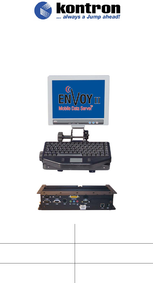
Base System
The CVX Server consists of the following additional features, some of which are optional
depending on the model purchased:
CVX Server Description:
Model: CVX-1700PM
Operating System:
Windows 2000
Windows XP PRO
System RAM:
512 MB or 1 GB
Memory is internal and not user accessible.
• QS3 CPU module with 1.70 GHz (or higher) Intel Mobile Pentium M processor
• Rugged, lightweight, aluminum alloy construction tested to specific U.S. Military
standards for resistance to shock, vibration, and humidity
• 40GB master removable hard drive (60GB upgrade available)
• 512 MB standard SDRAM (upgradeable to 1 GB)
• Windows 2000 and XP Professional operating system support
• 2 PCMCIA slots accept two type II devices or one type III device
• Video RAM, 8-64MB (shared)
• Wide range of optional components
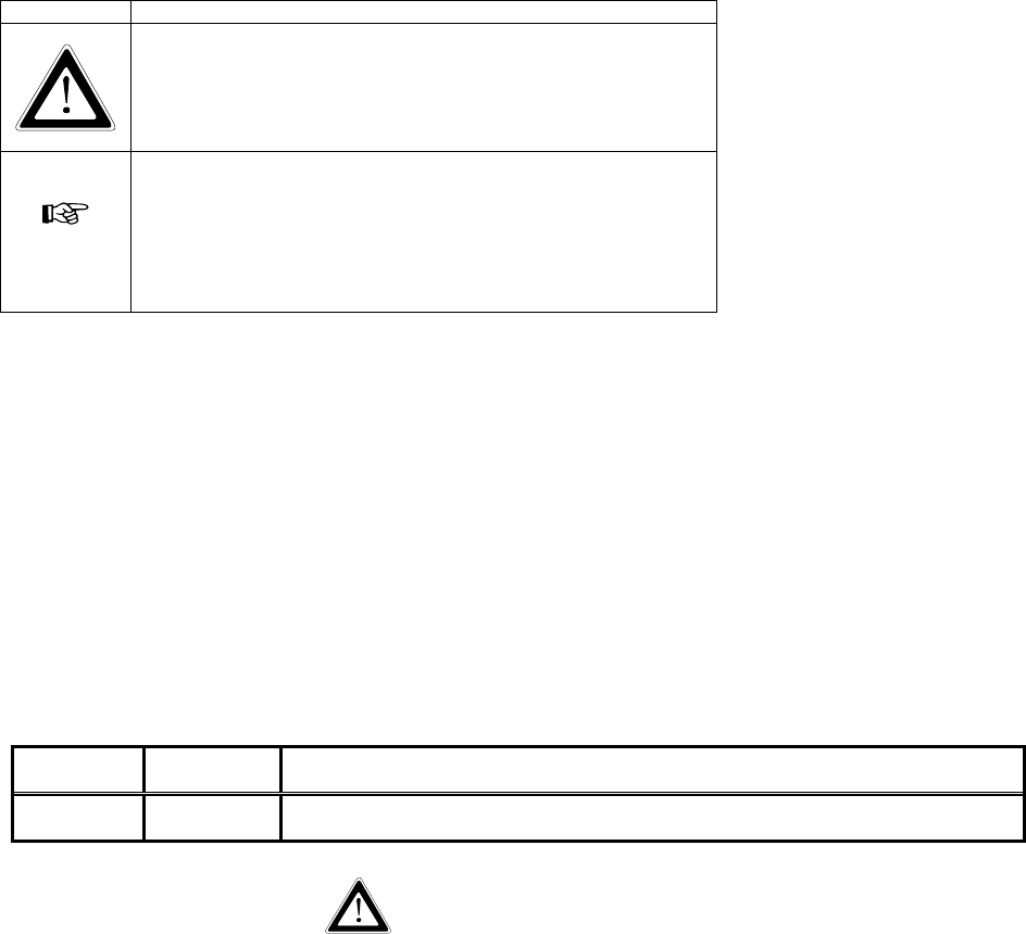
Optional Display and Cables
The optional display is a LVDS (Low Voltage Differential Signaling) LCD (Liquid
Crystal Display) touch screen that is 12.1” in size.
LCD Display (12.1”)
Model: ENVII-DSP121
20 Ft. Cables:
LVDS: 055-0385
Control: 055-0381
6 Ft. Cables:
LVDS: 055-0394
Control: 055-0395
Envoy II / CVX User Manual Page 10
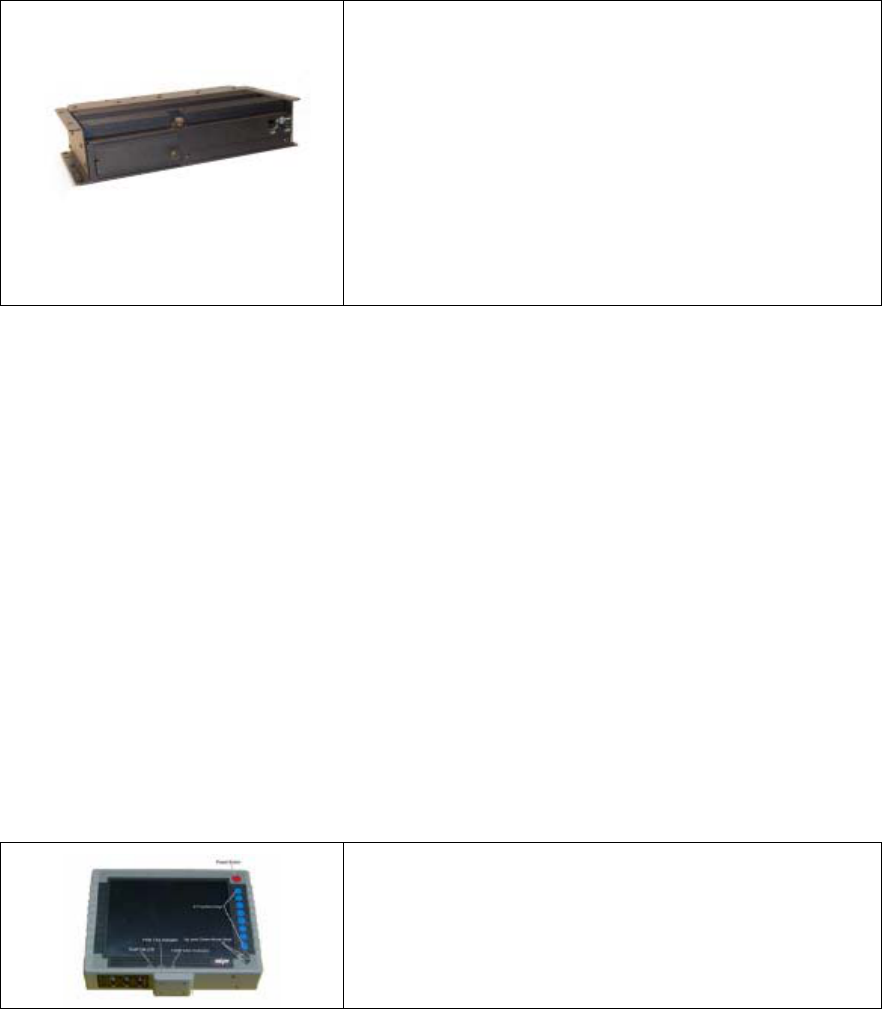
Optional Keyboards
There are a couple of optional keyboards that we’ve certified with our product. These are
optional purchases with your touch screen.
Keyboard
Model: KB-TP-E
Integrated mouse
3 levels of backlighting
Tactile Keyboard
Model: KB-TG
Sealed from top only
7 levels of backlighting
NEMA testing has not been done for this
product. Built to NEMA4 specifications by
manufacturer.
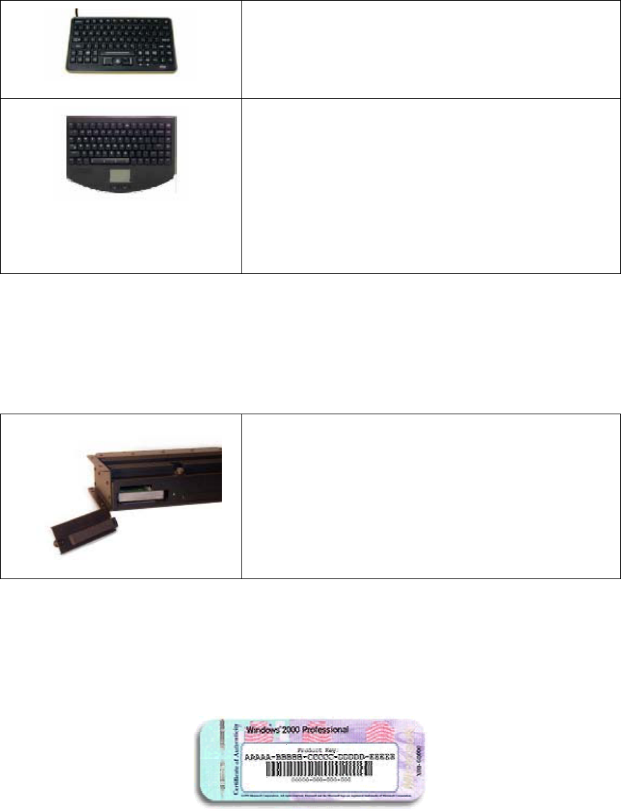
Hard Drive
The hard drive is normally a 40 GB drive, but sometimes it’s a 60 GB drive if that
upgrade was purchased. It’s important to note that if you buy the Windows operating
system with your purchase we will install it on your hard drive.
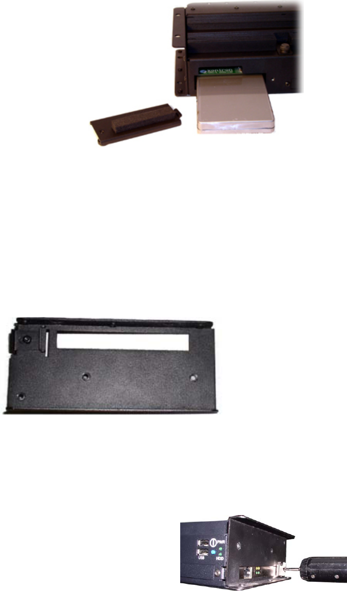
Removable Hard Disk Drive
Model: RHDE2-40G, RHDE2-60G, RHDE2-
HT40G, RHDE2HT60G, REME2-60G, REME2-
40GHTD, or REME2-60GHTD
We will also place the Windows COA (Certificate of Authenticity) sticker on your hard
drive. Therefore, before you power on the system you should remove the hard drive and
copy the product key down.
The COA sticker should look similar to this image:
Envoy II / CVX User Manual Page 11
If you need instructions on how to remove your hard drive then please reference the
section titled: “Hardware Instructions > Hard Drive” and you’ll find step-by-step
instructions on how to locate and remove your hard drive.
Purchased Software
Although your purchased operating system comes preinstalled you should back up your
Microsoft Windows™ licenses in order to prove ownership. Kontron is not responsible
for maintaining your license information, and we will not be able to replace it if you lose
it. Please immediately check to ensure that you received the proper product key with
your unit.
Cables
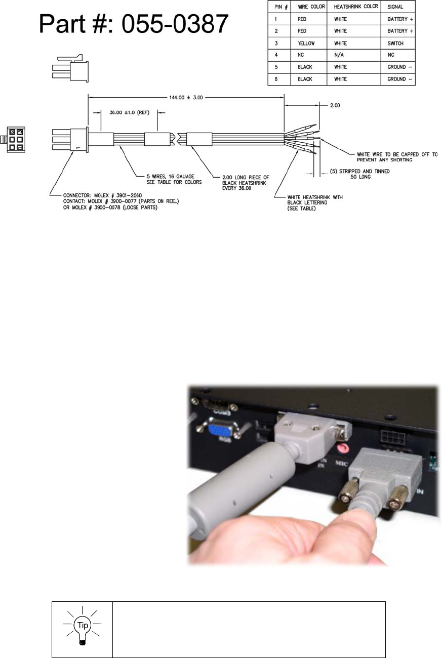
New orders should include a DC power cord (part #: 055-0387). You may also purchase
an optional AC power adapter with power cord. The model number for that is: PSE2-
ACUS.
If you purchased a touch screen display from us then you should have also received two
separate cables for that. One of which is a LVDS cable, and the other is a control cable .
Both cables are needed in for the display and touch screen to work properly. The touch
screen is also dependent upon the proper driver, which is covered later in the manual.
Connect the System
In Car Mount Solutions
If you purchased a car mount with this system please be aware
that installation directions will be included separately. Please
contact your Kontron sales representative for more information
regarding our in car mounting solutions.
Attach AC or DC Power
AC Power
The AC power cord simply needs to be plugged in to a
wall outlet, and the other connector just needs to be
plugged in to the back of the unit.
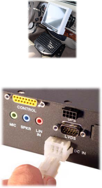
DC Power
The DC power cord has the connector you see in the
picture. The other end will have bare cables so you may
utilize any combination of wires that you see fit. A
drawing diagram of the pin out will be found on the next
page, and it’s on the CD that arrives with the Envoy
2/CVX. Which is also a higher quality drawing of this.
Envoy II / CVX User Manual Page 12
Attach a Display
LVDS
Install the Liquid Crystal Display (LCD) unit using the adapters and kits that have been
ordered. Then you may connect the cables when the unit is off. When tightening the hold-
down screws, seat the connector as much as possible. Then tighten the two screws to
ensure that both ends of the connector are fully seated.
1. Remove the protective
covers on the I/O connectors
labeled Control and LVDS,
located on the back panel of
the CVX Server.
2. Connect the end of the
Control cable marked to
Server to the I/O connector
labeled Control.
3. Connect the end of the
LVDS cable marked to
Server to the I/O connector
labeled LVDS.
Cables should be installed at the CVX Server first, to
guarantee that the correct polarity will be available at the
Display end.
Envoy II / CVX User Manual Page 13
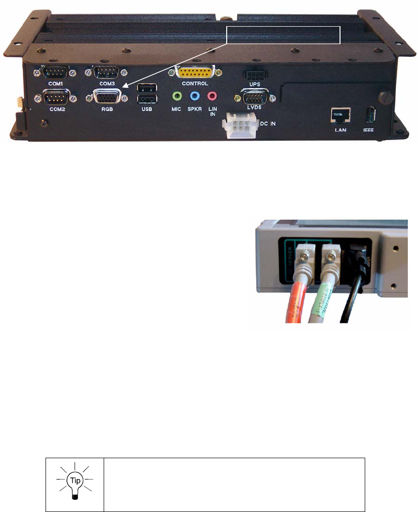
VGA
To attach an analog display has a RGB connector that plugs in to the port labeled RGB.
Please attach your monitor cable where the picture indicates.
RGB Monitor Port
RGB Monitor Port
Attach Input Devices
Keyboard through our Display
When tightening the hold-down screws, seat the
connector as much as possible, and then alternately
tighten the two screws to ensure that both ends of
the connector are fully seated.
If you haven’t already connected the LVDS and
control cables please power off the machine, and
follow these instructions completely:
1. Connect the keyboard to the black LCD connector labeled PS/2 KEYB/MOUSE
INPUT.
2. Connect the end of the control cable (#055-0381) marked by to Display to the
connector of LCD labeled KEYB/MOUSE.
3. Connect the end of the LVDS cable (#055-0385) marked LVDS to the connector
of LCD labeled LVDS.
Plug in the keyboard cable first, and then the two cables
from the CVX Server. This will prevent inadvertent swapping
of the two connectors with the same polarity.
Envoy II / CVX User Manual Page 14
USB Keyboard
If you don’t choose to use our display and keyboard you may use one of your USB ports
for a USB keyboard. With Windows 2000 and Windows XP most USB keyboards are
simply plug and play devices that don’t require any special drivers. Depending upon how
advanced your keyboard is you may need drivers if it has advanced features.
USB Mouse
USB mice are very similar to USB keyboards simply because most are plug and play.
However, some USB mice also require unique drivers if you want to fully utilize the
features available. Please check the vendor website in order to find the proper drivers to
download.
Connect Misc. Equipment
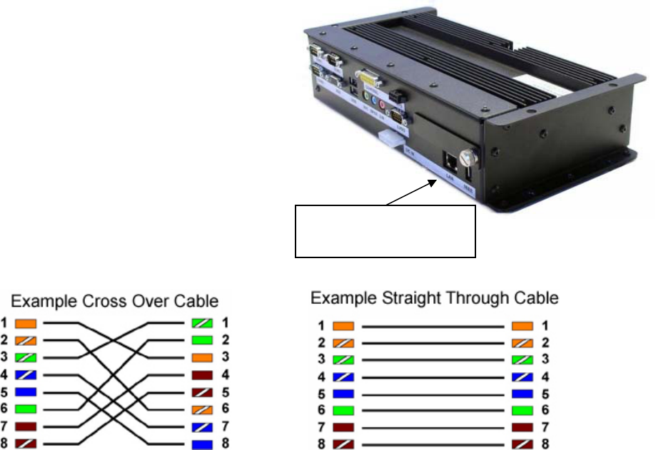
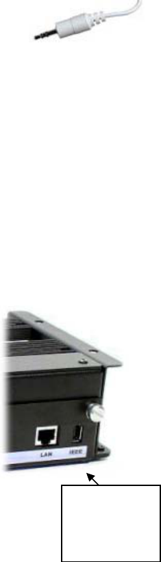
Ethernet
Plug in your
Ethernet cable here.
The first step of connecting your Ethernet
equipment is to make sure that you’re using
the proper cabling. If you’re connecting
from one CVX to another CVX you should
use a cross over cable.
However, if you’re connecting the CVX to a
switch or another similar device you’ll want
a straight through cable. Cross over and
straight through are terms that express how
the wires inside the connector are arranged.
For example a cross over cable internally may
look like this:
The other cable is called a straight through cable, and as the description says it’s a cable
scheme where the color-coded wires are the same on both sides of the connector. There
are different wiring schemes, and standards but functionality wise it shouldn’t matter as
long as you follow the proper cable scheme for connecting to the type of device you’re
using.
Envoy II / CVX User Manual Page 15
If you’re using our image from the factory then you already have the driver installed.
However, if you plug in your cable and things are still failing you should check the
device manager to ensure the driver is installed. For more information on how to install a
driver check the software section of this manual. For your reference we currently use the
Intel 82551ER network controller, which supports 10/100 Mbps.
Audio
Connecting any portion of your audio is as simple as connecting the
proper plug in to the back of the corresponding connector on the unit.
Speakers should be attached to the green line out, the microphone to
the red line in, and the line in is the blue connector.
COM Ports
Attaching a serial device to one of the COM ports is fairly easy. Our unit offers three
COM ports, and two of those are traditional COM ports. The third COM port is based on
the Texas Instruments 3410 chip as it runs over USB. Therefore the third port will
require proper drivers in order for the com port to work properly. Please refer to the
software DUDA (Drivers, Utilities, Documentation, and Applications) CD to retrieve this
driver. You may also refer to the software section of this manual for directions on how to
install a driver. From the factory all required drivers should be installed if you’re using
our software image.
Firewire
Our firewire port is a powered 12V (15watt) port that can be used
for self-powered devices, or by some cable powered devices.
There are different power classes for firewire, and it’s important
that system integrators understand the differences. It’s also
important to know that firewire is also referred to as IEEE 1394
as that’s the specification that it follows.
IEEE 1394
Port
(firewire)
For most users the port will simply be plug and play. Attach the
cable to the device and other six-pin connector to our machine.
Windows should recognize the device automatically, and it if it
requires drivers that Windows can’t find
it should prompt you to install them.
Other USB Devices
We have four USB ports on the actual system, and all four are powered ports. You may
use any device that consumes up to 500 mA of power from the USB port. Otherwise you
need to externally power your devices. All four ports can run in HiSpeed mode.
USB devices are plug and play so simply plug in the proper plug to the system and
Windows will see the device. You may need drivers depending upon the USB device.
Envoy II / CVX User Manual Page 16
Power On and Power Off
Turning On the System
Do not operate a CVX Server equipped with wireless capabilities in areas
sensitive to radio interference, such as airplanes and hospitals. You may
turn these devices off using the Windows OS.
1. Press the Power On/Off button for approximately 1/2 second. The computer will
check for valid temperature and turn on.
As the computer powers up, the LEDs blink and the AMI BIOS screen will
indicate that the computer is checking memory and preparing your system for
bootup. This is the Power-On Self Test (POST) screen. Once POST has finished,
a System Configuration screen briefly shows information on how the system
BIOS is configured.
2. To check the configuration at length, press the Pause/Break key as soon as the
System Configuration comes up on the display. You may then press Enter to
continue. The system will then proceed to load the installed operating system.
Never operate this computer in AC mode while standing in water.
You can operate it in DC or battery mode.
If you should encounter a problem in powering up:
1. Verify all connectors are properly connected.
2. Verify your boot drive.
3. Boot your system with only the power cord connected to the
computer. This is the minimum required to see if the system is
working.
4. If your system still does not start after steps 1-3, contact your
nearest Technical Support department for assistance. See the
“Technical Support” section of this manual for contact information.
Turning Off the System
Kontron recommends that you close all
applications before shutting down or powering off
the CVX Server.
1. Always power down by following the procedures specified in the operating
system manual, OR if this fails,
2. Press the Power On/Off button and hold it down for approximately 1/2 second.
The system should then begin to turn off. If it fails you may continue to hold the
power button and it will perform a hard off.

Envoy II / CVX User Manual Page 17
Resuming the System from a Power Savings Mode (ex. Standby)
To awaken the CVX Server from a sleep mode, briefly
press the Power button.
In Microsoft Windows there are different power savings states. In order to resume out of
these modes you can normally just push the power button on your system, or you may
use the power button on your touch screen.
However, in Microsoft Windows you also have the option of allowing some USB devices
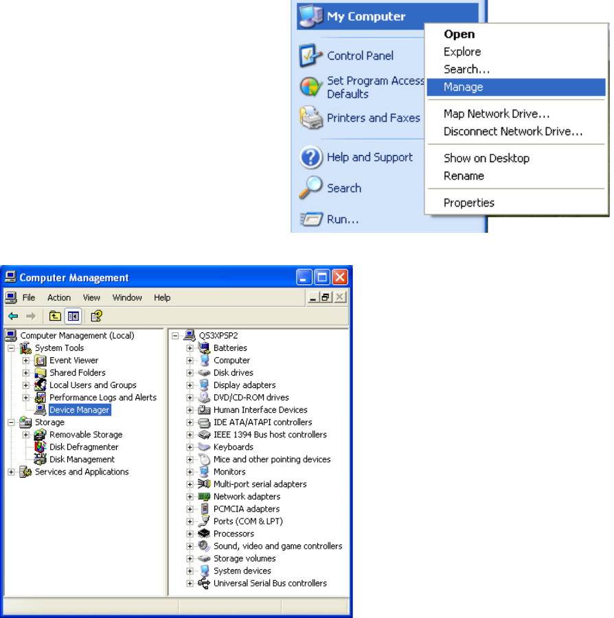
to awaken the system. You must enter the device manager in order to set this option.
Each version of Windows is slightly different, but generally you can right click My
Computer and choose Manage. From there click the Device Manager text on the left
hand side, and your devices will appear. Expand the section your device relates to, for
example Mice and other pointing devices. Double click the device you want to wake the
system up, and look for a power management tab. If you see that tab you can check the
box that says “Allow the device to bring the computer out of standby.”.
By checking that box whenever that device is sending activity, it will pull Windows out
of a standby power mode.
Troubleshooting Blink Codes
The Power Indicator LED is located next to the Power On/Off button on the right front
panel of the CVX Server. The Hard Disk Drive (HDD) Indicator LED is located
directly below the Power Indicator LED. Refer to the photograph above for exact
locations.
As listed in the following table, flashes on the Power LED indicate the power states:
Power Indicator
LED System Power
State Operation
Rapid Blink Any State Power change
requested
Two Long, One Short Delayed Start Heater is on, power on
pending
One Long, Two Short Delayed Start Temperature power-up
inhibit
One Long, One Short Off Power system problem
OFF Off System is off
Slow Blink Off Charging battery
Blink Twice Off Heater is on
Rapid Blink On Low battery
Slow Blink On Sleep mode
ON On System is on
Pause – Quick Blink On Power brown-out
One Long, Three Short On Temperature sensor
fault
Envoy II / CVX User Manual Page 18
The First Boot Up
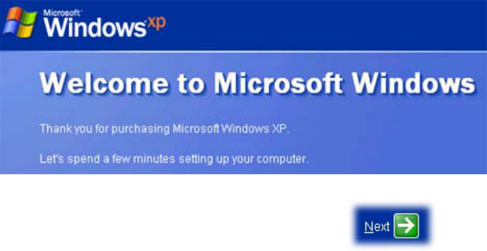
Windows Out of Box Experience
The Windows Out of Box Experience (OOBE) is the first screen that you should see if
you purchased Microsoft Windows with your computer. The Windows XP version is
shown below:
At this screen all you have to do is push the Next > arrow:
1. The next page will prompt you to agree to an End User License Agreement
(EULA), and you must accept it if you wish to continue. Make your selection and
click the Next arrow once again.
2. From here you have to enter the product key. This is the set of numbers that are
on your hard drive. If you followed this manual you should have written this
down after reviewing the hard drive section. If not please return to the hard drive
section for instructions on how to retrieve your product key. Enter this number,
and then click the Next button once again.
3. The following page will name your computer. This name isn’t private, and it
should be unique. It will be visible to everyone else that is connected to the same
network as you. After naming your computer you may push Next again.
4. This page will set up your administrator password. This is very important
because this account will have complete access to your machine. Please make
sure that you choose a password that you can remember. Enter that and push the
Next button again.
5. Now this page will ask you for usernames that will be using your computer. You
may enter as many usernames as you would like, but you must enter at least one
name. Do so and then you may push Next.
6. View the “Thank you!” message, and then you may push the Finish button.
From here your Windows machine will initialize the new settings, and present you with a
login screen. Click on your login name, and you may begin to use windows.
Envoy II / CVX User Manual Page 19
No Operating System Installed
If you order the units with hard drives, but without an image when you first turn on your
system you’ll see an error message. The error message will say: “Reboot and Select
proper Boot device or Insert Boot Media in selected Boot device and press a key”
You should use a USB CD-ROM or a USB Floppy Drive to install an operating system
image on to your system. You may also enter the BIOS in order to see all available boot
devices. For more instructions on the BIOS please refer to its section in this manual.
Hardware Instructions
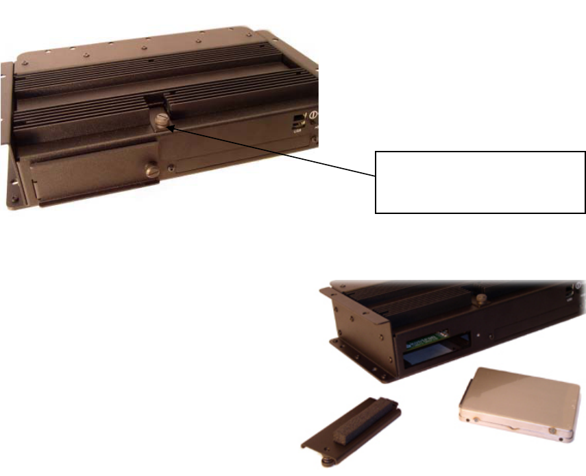
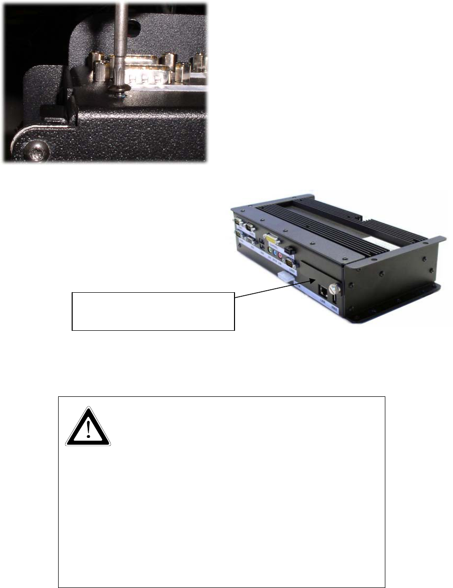
Fuses
There are fuses located under a panel at the top of the unit. The arrow here points to the
screw that must be loosened in order to access them. We currently use two 10 amp fuses.
Fuse (2x)
(under removable door)
Hard Drive
Remove the Hard Drive
1. Power off the CVX Server.
2. Locate the large thumbscrew on the
front left-side door.
3. Loosen the large slotted screw.
4. Remove door and set aside.
5. Using the tab attached to the HDD
case, pull out and remove HDD.
Envoy II / CVX User Manual Page 20
Add the Hard Drive
1. Power off the CVX Server.
2. Remove door as described
above.
3. Slide in the HDD until it snaps
into place.
Do not apply excessive force:
If it doesn’t feel as though it
fit together ensure that you
aren’t trying to insert it
incorrectly.
PCI
In order to add or remove a PCI card you will need to remove eight (8) screws from the
side of the case. They are torx head size 10 screws, so please use the proper tool for
removal. There are three screws on the very bottom (PCI slot side), four screws on the
PCI slot cover side (one of which is the lock for the PCI card), and one on the back I/O
board next to the COM2 label.
By removing these torx screws, you should free up this sidepiece for removal:
After that piece is removed you can insert your PCI card in to the PCI slot. If you need
leverage to insert the PCI tool you may use a non-conductive tool such as a wooden
pencil in order to have a better angle with more leverage. Optionally you may request us
to install this at the factory. Please contact your sales representative for more
information.
After the card is inserted you will have to put the panel
back on, and you will have to lock the PCI card in to
place. Picture to the right you will see where the PCI
lock is located.
Envoy II / CVX User Manual Page 21
After locking the card into place you should
double check it to make sure the card is
seated, and that nothing is shorted out. Once
you’re absolutely sure put the other three
screws on this side back on, then the three on
the bottom, and finally the one other screw
pictured to your left.
Once all eight screws are back in place you
may hook up your connections again. Power
on the machine and your plug and play card
should be detected in Windows.
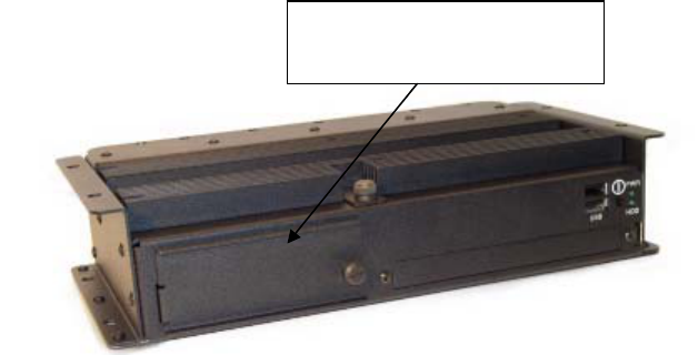
PCMCIA
PCMCIA is supported on this machine, but
you must remove the back door in order to
access the slots. More details will be
covered on the next page.
PCMCIA ports
(behind removable door)
Two PCMCIA slots on the back interface panel accept two Type II PC Cards or one Type
III PC Card. You can insert and remove the cards while the computer is on. The
PCMCIA slots are located behind the removable door on the right back panel of the
Server, as shown below.
• The peak power consumption of each of the PCMCIA
slots may not exceed 3.3 Watts Peak (600 mA at +5 V).
• Follow the card manufacturer's instructions in the PC
Card documentation.
• Do not force a PC Card into or out of the slot.
• Prevent external debris from entering the slot.
• Make sure that the PC cards all have the legally
prescribed approvals (e.g. IEC/EN 60950).
• The CVX Server has an extended temperature range.
This might be not the case with your PC Card. Please
note that the operating temperature range could be
decreased for the whole system depending on the
manufacturer’s recommended temperature range for
the PC card that you want to use.
Envoy II / CVX User Manual Page 22
Compact Flash
Compact Flash (CF) slot
(behind removable door)
The compact flash port is accessible by removing
the front cover, by looking right above
the hard drive, the board, and then you’ll see
the compact flash connector.
Inserting your device should
allow Windows to instantly
recognize, and initialize it.
Envoy II / CVX User Manual Page 23
Hardware Specifications
Server Processor
Intel® 735 Pentium® M
processor at 1.7GHz
System bus: 400MHz
Video Chipset
Intel® 855GME chipset
OS Support
Windows® 2000 Professional
Windows® XP Professional
Linux®9 Kernel 2.6 Validated
Chassis Construction
A solid, conductive cooled, rugged
unitized aluminum construction protects
internal subsystems from shock and
vibration.
RAM/Cache
512MB DDR 333MHz DRAM
(PC2700), upgradeable to 1GB
64MB Video DRAM
Standard 2MB L2 cache
Removable Rugged zed 2.5-inch Hard
Drive
40GB ATA/100 removable hard
drive module - standard
60 ATA/100 removable hard
drive module - optional
Heated hard drive upgrade for
expanded operating temperature
spec.
Embedded Expansion Slots
PCMCIA card bus slots that
accommodate two Type II or one
Type III devices
One open CF slot
(CompactFlashmedia)
One 5.8-inch length PCI card slot
for DVR, data acquisition, etc.
One open Mini PCI slot for
802.11g wireless LAN or other
technology
External Keyed I/O Connectors with
Strain Relief System
Power
Locking Vehicle power
connector
UPS
Locking Vehicle Smart Battery
connector
Video
One LVDS output (640 x 480,
800 x 600, 1024 x 768) and one
RGB analog output
(simultaneous different image,
different resolution)
Sound
Amplified stereo speaker out,
stereo MIC-in and Line-in
Control Port
Remote momentary power on/off
switch signal, PS/2 mouse and
keyboard signals, system
controlled 12V DC 4A power out
Mouse/Keyboard Interface
Electronically compliant IBM®
PS/2 via control port
Serial Ports
Two open RS-232 ports and one
USB RS-232 port
USB
Four bootable USB 2.0 ports (two
on front of unit, two on rear)
High Speed Digital IEEE 1394 Port
Powered port: 12V, 15W
Envoy II / CVX User Manual Page 24
Network
RJ45 Ethernet LAN -
Intel 82551ER 10/100 Mbit
Power button, HDD activity LED and
Power LED
Internal I/O Connectors
2nd IDE channel for integrated
optical drive or DiskOnChip®
Smart Battery port for integrated
battery
Server Physical Characteristics
Weight
5lbs (2.3kg)
Server Dimensions (W x H x D)
6.9 X 2.8 x 11.63-inch
(17.52 x 7.11 x 29.54cm)
LCD Weight
9 lbs
LCD Dimensions (W x H x D)
12 x 9.5 x 3-inch
(30.48 x 24.13 x 7.62cm)
Temperature and Power
Management Systems
Temperature management system
will not allow system to turn on at
temperatures below -15 °C (5
°F)
Optional extended temperature
option controls heating system to
hard drive and other system
components at temperatures
below 0 °C Parameters can be set
through the BIOS.
Power Management System
ACPI Compliance, (Standby,
Suspend and Hibernate (S1, S3,
S5)
UPS Port Optional Smart UPS
allowing for user-definable
graceful shutdown
Modes after power failure Smart
UPS allows for a minimum of
5min
Brownout protection in 12 and
24V DC vehicles to 6.5V DC for
30sec
Internal DC to DC converter with
power input range of 10 to 30V
DC
500ms debounce protection on
power switch
Two externally accessible mini
car fuses and reverse polarity
protection
Graceful shutdown and inactivity
timers
Auto on vehicle key signal on
power connector for remote
power on and graceful power
down
Power LED error code status
codes for troubleshooting
System controlled 12V DC 4A
power out on control port
Environmental Operating
Temperature
-15 ° to 60 °C (5 ° to 140 °F)
Non-operating Temperature
-25 ° to 60 °C (-13 ° to 140 °F)
Optional Expanded Operating
Temperature for Server
Extended Operating Temperature
Option
-40 ° to 60 °C (-40 ° to 140 °F)*
Non-operating Temperature
-25 ° to 60 °C (-13 ° to 140 °F)
Extended Cold Start Temperature
-25 ° to 60 °C (-13 ° to 140 °F)*
*Power applied to unit at all times
Envoy II / CVX User Manual Page 25
Operating Humidity
10 to 90% relative humidity, non-
condensing
Mil-Std-810F, Method 507.4, storage
humidity: 5 to 95% relative humidity,
non-condensing
Operating Shock
40g @ 45 to 200Hz; 18 drops
Non-operational Shock
75g @ 80 to 2000Hz; 12 drops
Functional
Mil-Std 810F, Method 516.5, Procedure I
Crash Hazard
Mil-Std 810F, Method 516.5, Procedure
V
Vibration
Mil-Std 810F, Method 514.5, Procedure
1, Cat20, Table 514.5C-VII, Figure
514.5C (US highway truck)
Operating Altitude
-300 to 3000 meters
Non-operating Altitude
-400 to 5,000 meters
EMI/EMC
FCC Class A, CE Class A
Safety
ETL, CETL
Envoy II / CVX User Manual Page 26
Software
Installing an Operating System
Windows 2000
Installation of Windows XP will require a USB based CD-ROM drive, and your
Windows product key. In our testing we primarily used the ASUS 5232A CD-RW.
Make sure you power the device on because all CDROM drives require more power than
the USB cable can provide. At this point turn on the CVX, and while it’s at the POST
screen push the F11 key for the boot menu. Select your USB CD-ROM from the list, and
then Windows should prompt you to push any key to boot from the device. Push any
key, let setup continue to load, and when it prompts you to push Enter to setup Windows
2000 now.
From there the process should look like this:
Push F8 to accept the license
Select the partition that you wish to install Windows on, and if none exist push C
to create one.
Format the partition in NTFS. This will erase all data that is currently on that
partition. Back up any data on the machine before you proceed with this step.
The installer should restart and present a graphical interface where you select your
keyboard layout or location settings. Select the proper information and click
Next.
Type in your name and your organizations name. Click Next to proceed.
At this point you have to enter your product key. If you haven’t already
documented this key it can be found on your removable hard drive. Please refer
to the hard drive section of this manual for instructions on how to safely remove
your hard drive.
Enter a computer name, and an administrator password. The computer name will
be visible on the network so ensure that it adequately describes the machine.
Set the current date, time, and time zone.
Choose Typical Settings unless you are familiar with network configuration, and
then click Next.
Set your computers workgroup to the same workgroup ID that your others
computers use. If you’re using this in a corporate environment then you should
contact your IT department to determine if you need to configure the machine in a
domain (active directory) environment.
Setup will copy all of the files to your system, and then click the Finish button to
restart the machine in Windows.
Envoy II / CVX User Manual Page 27
At this point Windows will prompt you for any necessary information, and it will
boot you in to the Windows operating system.
Use the CD we include with our systems to reinstall the drivers, and your machine
should now run properly. For driver installation instructions please read the
driver portion of this manual.
Windows XP
In our testing we primarily used the ASUS 5232A CD-RW. Make sure you power the
device on because all CDROM drives require more power than the USB cable can
provide.
At this point turn on the CVX, and while it’s at the POST screen push the F11 key for the
boot menu. Select your USB CD-ROM from the list, and then Windows should prompt
you to push any key to boot from the device. Push any key, let setup continue to load,
and when it prompts you to push Enter to setup Windows XP now.
From there the process should look like this:
Push F8 to accept the license
Select the partition that you wish to install Windows on, and if none exist push C
to create one.
Format the partition in NTFS. This will erase all data that is currently on that
partition. Back up any data on the machine before you proceed with this step.
Windows will begin to copy all of its data files on to the machine.
Set the regional and language options, and then press next.
Then set your name and the organization, and then press next.
Enter your windows product key in the five blanks provided. If you don’t have
this information review the section of the manual titled: “Receiving Checklist >
Hard Drive” After entering this information you should press next.
At this step choose typical network settings unless your IT department instructs
you to do otherwise. These options can be changed later in Windows. Click Next
once you are ready to do so.
You will see a message box saying that to improve the appearance of your visual
elements, Windows will automatically adjust your screen resolution. Press OK,
and then press OK again.
The Welcome to Microsoft Windows screen comes up. At this point please refer
to the Windows Out of Box Experience section in this manual to continue setting
up your system.
Envoy II / CVX User Manual Page 28
Configuring your System
Installing Drivers
On occasion when you hook up a new
device or when you re-install the
operating system you will have to
reinstall drivers. All devices require
drivers in order for the operating system
to know how to use that device. The best
way to determine the current status of
your drivers is to open the device
manager. You can do that by right
clicking my computer and choosing
properties.
After doing so you should see the
Windows Device Manager window: If all your devices are working
properly it should look like the
image to the left. If there are any
yellow exclamation marks or
question marks in front of your
devices then there is an issue that
needs your attention.
Normally both errors are due to
drivers not being installed or the
improper driver being installed.
Double click the device with the
problem, click the Driver tab, and
then click update driver.
Now insert your driver disk in to
an external USB drive and click
next. After scanning the CD the
driver should automatically be
matched up with the proper files.
If it doesn’t find a match then you may either have the wrong CD in or the driver files
may be in a compressed format. Some times installers store the drivers inside of a
compressed .EXE file, and you have to run their setup in order to install the drivers.
Please refer to your devices documentation in order to learn how to install that specific
driver. All of our drivers are found on the companion CD that ships with the unit.
Envoy II / CVX User Manual Page 29
Audio – Adjusting Volume
The CVX contains a 2 watt bridged amplified audio. In order to use this functionality
you must first physically connect the device. Instructions may be found at the Connect
Misc. Equipment > Audio section of this manual.
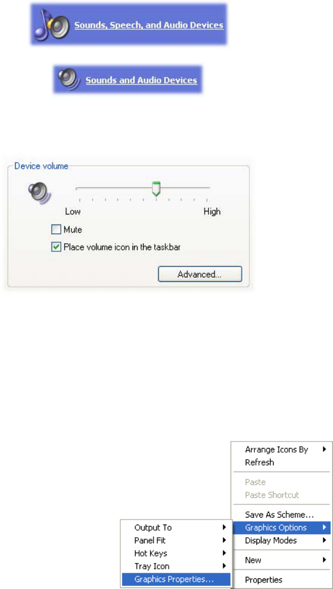
Once physically connected you should click your Start button, and go to Control Panel.
Using Windows XP you will see a Sounds, Speech, and Audio Devices section:
After clicking that you should see another section that says:
Click this and you will see the audio properties, and on the first tab it will say volume.
From here you can slide the indicator to the left to decrease volume, or to the right to
increase it. If you aren’t hearing any audio it’s important to check that you don’t have the
checkmark next to mute.
Windows 2000 is very similar, but after going to the control panel you will double click
the Sounds and Multimedia icon. From there you can use the sliding bar under the Sound
Volume section.
Video
The Intel 855GME driver handles the video for the CVX/Envoy 2. We recommend that
our customers use the Intel utility to manage their display instead of using the Windows
Display Settings.
In order to use their utility you must first
already have the graphics driver installed
from the CD that we include with the
system. However, if you purchased a
hard drive and Windows with your
system this tool will be preinstalled on
your machine.
Envoy II / CVX User Manual Page 30
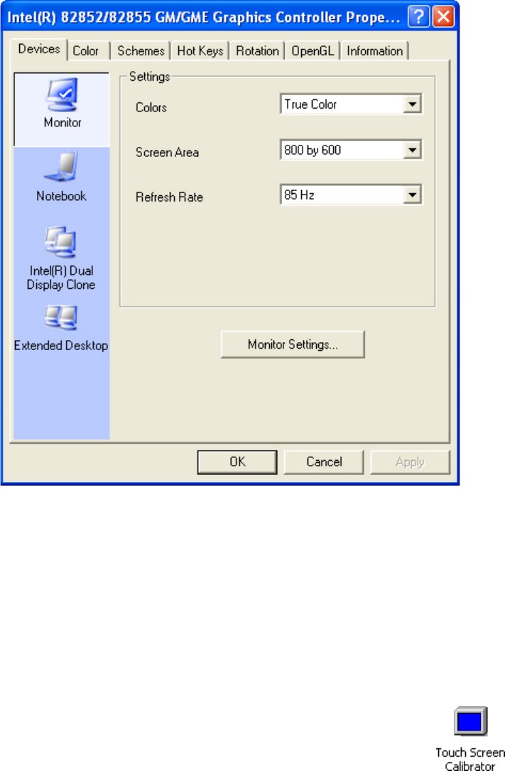
Right click your Desktop and choose Graphics Options > Graphics Properties. At that
point the Intel utility should open to display a menu similar to the one you see below.
If you select the Monitor icon the video will only be outputted to the monitor, and if you
select the notebook it will only go to the LVDS display. Intel Dual Display Clone will
send the same image to both displays at 800x600. The Extended Desktop option will
basically create one large monitor that can be dragged from one display to the other. If
you want two monitors on the same system without the displays showing duplicate
content then you’ll want the extended desktop option. Change the screen area
(resolution) and refresh rate may change as well. Then press the Apply button to use the
new settings, and finally push OK to close the window.
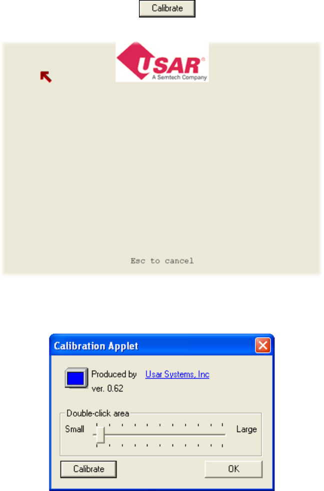
Touch Screen Calibration
If you notice that your touch screen doesn’t appear to be accurate then
chances are it needs calibration. In order to do that you need to click
Start > Control Panel and once there double click the calibration icon.
Envoy II / CVX User Manual Page 31
From there you should push the Calibrate button.
At this point you will see a standard calibration image such as the one below:
Using your finger or stylus touch the tip of the arrow shown on the screen, and then move
on to the next point. You will have to touch the arrow in all four corners before your
touch screen is properly calibrated.
If you use this same utility you may also adjust how large of a double click area you
would like. Expand this area if you notice that double clicking becomes challenging with
your touch screen.
Envoy II / CVX User Manual Page 32
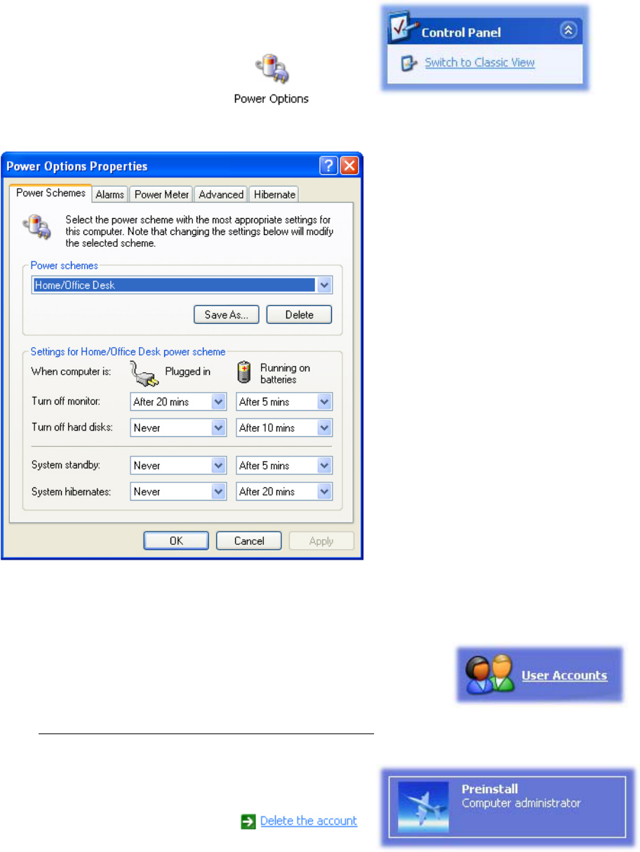
Power Management and Intel Speed Step Support in XP
The first step is to click Start > Control Panel. From
there you need to switch to the classic view in order
to see the Power Options icon:
After double clicking that icon you should see the Window below:
This window should be relatively
self-explanatory. It allows you to
set power management modes for
when plugged in to a power
source, or when you’re running a
battery through the Smart UPS
port.
It’s also important to note that by
using the Power Schemes section
you will change the Intel Speed
Step settings. That allows you to
conserve power consumption by
allowing the Intel Pentium M
processor to optimize itself to
conserve power.
Removing the Preinstall user account
If Kontron installed your Windows operating system then
chances are you will see a preinstall user account when you first
turn on your system. If that’s the case you may remove it as
long as you first create a new user account to replace it, and then sign in to that account.
After that the first step is to click on the Start button and then the Control Panel icon.
Once the control panel is open click on the Users
Accounts icon. Then click the Preinstall account,
and finally click the link that says:
Envoy II / CVX User Manual Page 33
Maintaining Your Purchase
Clean the System
Clean all other areas of the computer with a damp, soft cloth. You may dampen
the cloth with water or a mild household cleaner. If you use a mild cleaner, wipe
the computer again with a damp cloth only, and then with a dry cloth.
• Do not use strong solvents, such as benzene, thinner or
rubbing alcohol that could discolor paint or plastic.
• Do not use commercial household cleaners or cosmetics,
as they may harm the surface.
• Do not spray water, as liquid may damage the computer or
cause it to work improperly.
Clean the Display
If you are using a Kontron display, clean the display surface with a soft cloth. You can
use a slightly dampened cloth if the display is soiled, but DO NOT apply an abrasive
substance or other materials.
• Avoid using sharp objects such as pen or pencil tips
because they can permanently damage the touch pad’s
surface. Use the stylus provided.
Optimize your Hard Drive
After using your Kontron system for a while
you will notice that your performance
deteriorates. In order to maintain your hard
drive you should occasionally run scan disk,
and the disk defragmenter tool. These tools
will fix file system errors, attempt to recover
bad hard drive sectors, and it will organize
your hard drive so applications will find their
data on the hard drive even faster. Before
using these tools make sure you close down
all other unnecessary software.
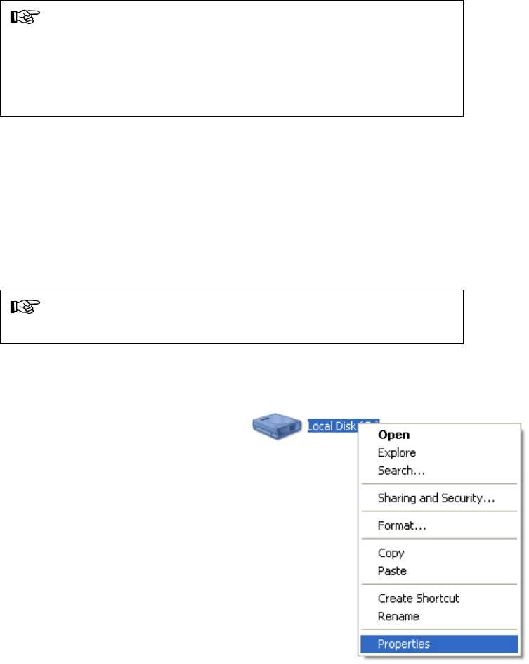
To use these tools you should first go to “My
Computer”, and from there right click your
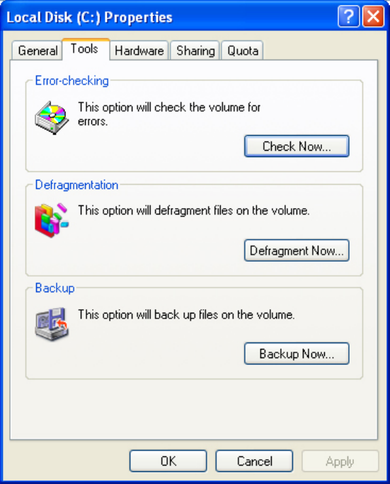
hard drive and choose properties. The next screen will look like the following image.
Envoy II / CVX User Manual Page 34
The first step is your scan
disk, and clicking the “Check
Now” button under Error-
checking will launch this tool.
After you’ve completed that
test you should click the
“Defragment Now” button
under the Defragmentation
section. This will organize
your hard drive, and as a
result your performance will
increase.
It’s important to regularly run
both the scan disk, and the
disk defragmenter in order to
keep your hard drive
optimized.
Envoy II / CVX User Manual Page 35
Introduction to the AMI BIOS
The BIOS user manual covers the AMI BIOS version 8. It mentions the features offered
and it describes the functionality of each feature. This manual was created and
distributed by Kontron America, the Mobile Computing Division.
Various features will look and perform differently from the documentation. BIOS
changes will impact how accurate this manual is and it’s important to take this in to
consideration. If you are not familiar with the BIOS settings then please leave these
alone unless you are instructed to change them by an authorized Kontron representative.
The AMI BIOS was chosen for features such as:
Fast POST times
Booting from different devices in your predetermined order
ACPI Support
BIOS Recovery Options
Resource Management
Power Management
… and for many other reasons.
In order to enter the BIOS you must hit your DEL (Delete) key during bootup. It will
prompt you to push this key to enter the BIOS. If you received a BIOS error it will ask
you to push F1 to enter the BIOS to fix the problem. You must enter the BIOS to see any
of the menus that we mention in this documentation.
The Menu System
The BIOS is completely keyboard driven, and as a result you have to use the
arrow keys to navigate around. Certain keys will universally work under any
BIOS menu, as long as you aren’t being prompted to change a setting. These
universal keys are listed below.
Universal Menu Keys:
θ
θ
θ
θ
F1 – Help Menu system
F2 or F3 – This will toggle between different color choices for your personal
preference. Some options have higher contrast and may be easier for you to
read.
F7 – Discard Changes, but don’t leave the BIOS.
F8 – Load Failsafe Defaults, but don’t leave the BIOS.
Envoy II / CVX User Manual Page 36
θ
θ
θ
θ
θ
θ
θ
θ
θ Main
θ Advanced
θ PCIPnP
θ Boot
θ Security
θ
θ Exit
F9 – Load Optimized Defaults, but don’t leave the BIOS.
F10 – Save the current configuration and exit the BIOS. This will cause a
reboot.
Home key– This instantly takes you to the top of the screen.
End key – This instantly takes you to the bottom of the screen.
Page Up– This will scroll down the page for quicker browsing.
Page Down – This will scroll up the page for quicker browsing.
Changing Selected Options:
The Plus key – This combination will select the plus sign (+) and that will
toggle your options.
The minus key (-) – This will toggle options in the opposite direction of the plus
sign.
Once you learn basic navigation you’ll have a number of menu choices to choose
from:
Chipset
Use the left and right arrow keys in order to change between the menus. The
choices listed above are in order, if you’re browsing horizontally. Each menu will
be covered in more detail on the following pages.
Envoy II / CVX User Manual Page 37
Main
The main menu is the first menu that appears after you enter the BIOS menu. It
will give you a brief system overview that covers information such as:
θ
θ
θ
θ
θ
θ Speed
θ
θ
θ
θ
θ
θ
θ
θ
θ
The BIOS Name
The Version
The Build Date and ID
The Embedded Controller version number
Processor Type
Count – The number of processors
System Memory – The size of the currently installed memory
Below this information you will have two menu choices for the system time and
the system date. These are self-explanatory, and changing these settings is
quite easy.
Use the up and down arrow keys to highlight the time or date field and then use
+ or – keys to change the options. For more assistance with this please refer to
the previous section under “Changing Selected Options”.
After you change that number then you may hit Enter to select the next field to
the right. Repeat that until you’re happy with the setting and then you may use
the arrow keys for further navigation.
Advanced
This displays the advanced settings options for components such as:
CPU Configuration
IDE Configuration
SuperIO Configuration
ACPI Configuration
Event Log Configuration
USB Configuration
Platform Configuration
Envoy II / CVX User Manual Page 38
CPU Configuration
The Advanced CPU Configuration menu shows you a lot of information about
your processor such as:
θ
θ
θ
θ
θ
θ
θ
θ
θ
θ
θ
Manufacturer – We currently use Intel processors for our notebooks.
Brand String – This identifies the CPU such as the Pentium m and the speed
in MHz.
Frequency – The number of hertz used in a specified interval.
FSB Speed – This stands for the Front Side Bus, think of it as the speed
between the processor and other components on the motherboard.
Cache L1, L2, and L3 (L3 is Unused/Disabled)
Ratio Status and Value
There are also a few options listed below that. Those are covered below.
The first of which is the L3 Cache option. L3 cache is memory built in on the
motherboard that’s inbetween the CPU and system memory. However, with our
notebooks there is no need for the L3 cache, and therefore this option should
remain disabled.
The option below that is for Hyper Threading function and should be disabled for
our systems. At the current time we don’t use the Pentium IV processors for the
mobile environment, and therefore hyperthreading isn’t offered on our systems.
The next option is for Intel Speed Step™ Technology, and this will change the
systems performance based on your selection. You have the options below:
Maximum Performance – Always run at the fastest speed.
Battery Optimized – Run at a slower speed, but receive longer battery life.
Reversed – Runs the fastest on the battery, but with poor battery
performance. It will run slower when it’s on AC power, but it will consume less
power.
Automatic – Maximum performance on AC power, but battery optimized when
you’re using only the battery.
Disabled – No SpeedStep support, always-high performance, unavailable
system management.
Envoy II / CVX User Manual Page 39
IDE Configuration
This menu allows you to work with your IDE devices in order to configure them
and to gather information about them.
θ
θ
θ
θ
θ
θ
θ
θ
θ
θ
OnBoard PCI IDE Controller – Disabled turns off the controller and Primary
enables the controller.
Primary IDE Master –This shows your detected device, most likely the hard
drive. Choosing this and hitting enter will take you to a sub menu with options
for that device.
Primary IDE Slave – If your device is detected it will appear here, and you will
be able to configure it further by hitting enter.
Hard Disk Write Protect – This will prevent data from being written to the hard
drive as long as it’s access through the BIOS with this setting.
IDE Detect Time Out (sec) – The number of seconds to wait while attempting
to detect devices connected through an IDE connection.
ATA(PI) 80Pin Cable Detection – 80 pin IDE cables are less likely to
experience interference and therefore it allows you to have faster data
communication between devices. This will notify the host and device that such
a cable is being used.
Super IO Configuration
This section handles the input and output of devices, such as serial ports and
any parallel ports. It also handles the onboard floppy controller. Individual
options on this menu will appear below.
OnBoard Floppy Controller – Enables or disabled the floppy drive controller.
Serial Port 1 Address – Sets the device address or allows you to disable it.
Serial Port 2 Address – Sets the device address or allows you to disable it.
Parallel Port Address – Sets the device address or allows you to disable it.
Envoy II / CVX User Manual Page 40
ACPI Configuration
ACPI stands for Advanced Configuration and Power Interface. It allows the
operating system to take over device configuration and power management.
This is normally set to Yes, as long as your operating system supports it.
Windows 98, 2000 and XP support ACPI, but Windows NT does not.
General ACPI Configuration and Advanced ACPI Configuration are the menu
options.
General ACPI Configuration
θ
θ
θ
θ
θ
θ
θ
θ
θ
Supend Mode – S1 (POS) only or S1 & S3 (STR)
S1 – Suspend Mode, turn hard drives off
S3 – Suspend Mode, suspends the system to memory, everything else is
turned off
Repost Video on S3 Resume – Starts VGA BIOS on S3 Resume
S4BIOS Support – Enable this if Hibernation (Suspend to Disk) isn’t
supported by your OS.
Advanced ACPI Configuration
ACPI 2.0 Features – Enables advanced ACPI functionality for better
operability.
ACPI APIC Support – This is the advanced programmable interrupt
controller, it handles interrupts and timing.
AMI OEMB table – This is used for debugging purposes, please use the
default setting.
Headless mode – Operation without a display or input devices such as a
mouse or keyboard.
Envoy II / CVX User Manual Page 41
Event Log Configuration
θ
θ
θ
θ
θ
θ
θ
θ
θ
View Event Log – The time and date stamp along with any CMOS/BIOS
errors should be visible here.
Mark all events as read – This marks any unread messages as read so they
won’t appear when you choose to view the event log.
Clear Event Log – Erases everything in the error log to free up the space
Event Log Statistics – Shows the total size, the free size, and the number of
unread events.
PCI Error Logging – This toggles between enabling and disabling all logging
activity for PCI devices.
USB Configuration
This section will show you the module version for USB support and the USB
devices that are currently enabled. It also has a number of menu choices to
choose from:
Legacy USB Support – Enabled supports old USB devices, Disabled doesn’t,
and Automatic is enabled only when a legacy USB device requires it.
USB 2.0 Controller Mode – HiSpeed is 480 Mbps and FullSpeed is 12 Mbps
USB Mass Storage Device Configuration – Has a timeout value specified in
seconds to wait on USB devices to start after POST sends the message.
Platform Configuration
If your system supports outside control for factors such as thermal protection
then they will be listed under this menu.
Thermal Control – No Heater will disable the heater but leave thermal
protection on, System On will turn on the heater when the system is on,
Always will leave it on at all times, and Disabled stops the heater and disables
thermal protection.
Envoy II / CVX User Manual Page 42
PCIPnP
PCIPnP is a section to configure PCI (Peripheral Component Interconnect) and
PnP (Plug and Play) settings.
θ
θ
θ
θ
θ
θ
θ
θ
θ
θ
θ
Plug & Play O/S – Selecting yes allows Windows to manage your devices. If
you set it to No then the BIOS will configure all devices that can be used by
your system.
PCI Latency Timer – This is a fixed value that specifies clock latency. It’s
probably only needed by those developing PCI configuration software.
Allocate IRQ to PCI VGA – This will give a PCI based graphics card an IRQ if
it requests one. For our products it’s unlikely that you would use this option.
Boot
The boot menu handles the startup of your computer. We’ll cover each sub-
menu below.
Boot Settings Configuration
Quick Boot – If enabled this allows the system to skip some initial bootup
tests in order to load faster.
Quiet Boot – If enabled it shows a logo instead of the POST messages.
AddOn ROM Display Mode – Force BIOS will show a logo before the AddOn
ROM section, Keep current won’t show this.
Bootup Num-Lock – If turned on your numbers lock will automatically be on
when the system boots.
PS/2 Mouse Support – Automatic will enable it if there’s a PS/2 device,
Enabled always has it on, and Disabled turns off this functionality.
Wait for ’F1’ If Error – If enabled the user must push the F1 key to get past a
BIOS error
Hit ’DEL’ Message Display – If enabled it will prompt the user to push DEL to
run setup, this message is shown in POST.
Interrupt 19 Capture – Allows ROM’s to trap interrupt 19 (Such as Network
Controllers).
Envoy II / CVX User Manual Page 43
Boot Device Priority
This screen allows you to use the plus and minus signs on your keyboard to
shuffle the boot order of devices on your computer. For example placing a floppy
drive or CD-ROM before the hard drive so that you may boot from that media
before Windows loads.
Hard Disk Drives
Specifies the boot sequence of all installed hard drives. This is useful with dual
hard drives to ensure the system attempts to boot off the proper equipment.
Removable Drives
This shows available removable drives that the system may be booted from.
They can be disabled, and their order can be changed.
Security
The security option of the BIOS allows you to specify a supervisor password and
a user password. The supervisor has access to change options, and the user
option has the option of booting the machine past the BIOS. If a password is
specified it will change the status to show “Installed” at the top of this screen.
θ
θ
θ
θ
θ
Change Supervisor Password – This will create or change the current
supervisor password.
Change User Password – This will create or change the current user
password.
Clear User Password – This will clear the user password.
Boot Sector Virus Protection – This will monitor the master boot record for
changes. If you install a new operating system it will update this section.
However, if it warns you that the MRB has been changed and it asks you to
approve of the change.
Primary Master HDD User Password – This locks the hard drive with a
password so only the intended user has access to it.
Chipset
The chipset menu allows you to change settings for Intel’s north and south
bridges. Those bridges handle communication between different portions of the
motherboard, and they’re critical for proper system operability.
Envoy II / CVX User Manual Page 44
Intel Montara-GML NorthBridge Configuration
θ
θ
θ
θ
θ
θ
θ
θ
θ
θ
θ
θ
θ
θ
θ
Init Graphic Adapter Priority – Internal, External PCI, External AGP, or Auto.
Auto should remain selected.
Graphics Mode Select – This sets the amount of system memory that the
onboard graphics controller uses.
IGD – Device 2, Function 1 – This will enable or disable the integrated
graphics device.
Boot Type – This allows you to select the type of output device for the bootup.
VBIOS should remain the default.
Flat Panel Type – This is the resolution that your display is designed to run at.
(Ex. 1024x768 LVDS) The video output won’t look proper if this is set
incorrectly.
TV Standard – Based on your country you have different TV standards.
NTSC is used in the USA, Europe largely uses PAL, but sometimes SECAM is
also used there.
NTSC Minor Standards
PAL Minor Standards
SECAM Minor Standards
Flat Panel Scaling – Auto is the default setting, but you may disable scaling,
or force it.
Intel ICH4 SouthBridge Configuration
IDE – Enable or Disable the IDE controller
SMBUS – Enable or Disable the SMBUS Controller (System Bus)
AC ’97 Audio – Enable or Disable the audio controller
USB – Enables or Disables the USB host controllers
EHCI – Enables or Disables EHCP (Enhanced Host Controller Interface)
Envoy II / CVX User Manual Page 45
Exit
The exit menu gives you options to leave the BIOS menu or it lets you restore
BIOS defaults.
θ
θ
θ
θ
θ
Save Changes and Exit – This will save your current settings and reboot the
system.
Discard Changes and Exit – This will allow you to discard the settings you
changed and to reboot the system.
Discard Changes – This will reset the changes you’ve made to the way the
BIOS was when you entered, but it won’t reboot the system. You will remain
in the BIOS setup utility.
Load Optimal Defaults – This will load the most optimal BIOS settings for your
machine.
Load Failsafe Defaults – This will load safer default BIOS choices that are
useful when troubleshooting problems.

Envoy II / CVX User Manual Page 46
Technical Support
If you should encounter difficulties with your application or this product, or need
guidance on setting up your system, we are ready to assist you. Please contact our
Technical Support department at the following locations:
All returned merchandise must receive a valid RMA number from our technical support
department prior to the return. Once you have a valid RMA you may return the
equipment to the address that technical support provides.
USA:
Technical Support Central Time Zone hours are: 8:00AM to 5:00PM – Monday – Friday
TEL: (888) 343-5396 (Toll free in US and Canada)
(952) 974-7200
FAX: (952) 949-2791
E-mail: support@kontronmobile.com
When you call, be sure to have the following information on hand:
Unit part number (P/No #)
Serial number (S/No #) of the defective unit (found on the back of the unit).
The address you would like the unit returned to.
Then, explain the nature of your problem to the service technician.
If you have any questions about our company, the products, or the services we offer then
you may reach us at the aforementioned telephone numbers, by e-mail, or by writing to:
Kontron America
Mobile Computing Division
7610 Executive Drive
Eden Prairie, MN 55344-3677 USA