Kontron America KM2M800 Smart Services Developer Kit User Manual KM2M800 XX v0 1x
Kontron America Inc. Smart Services Developer Kit KM2M800 XX v0 1x
UserManual.wiki
>
Kontron America
>
KM2M800 User Manual
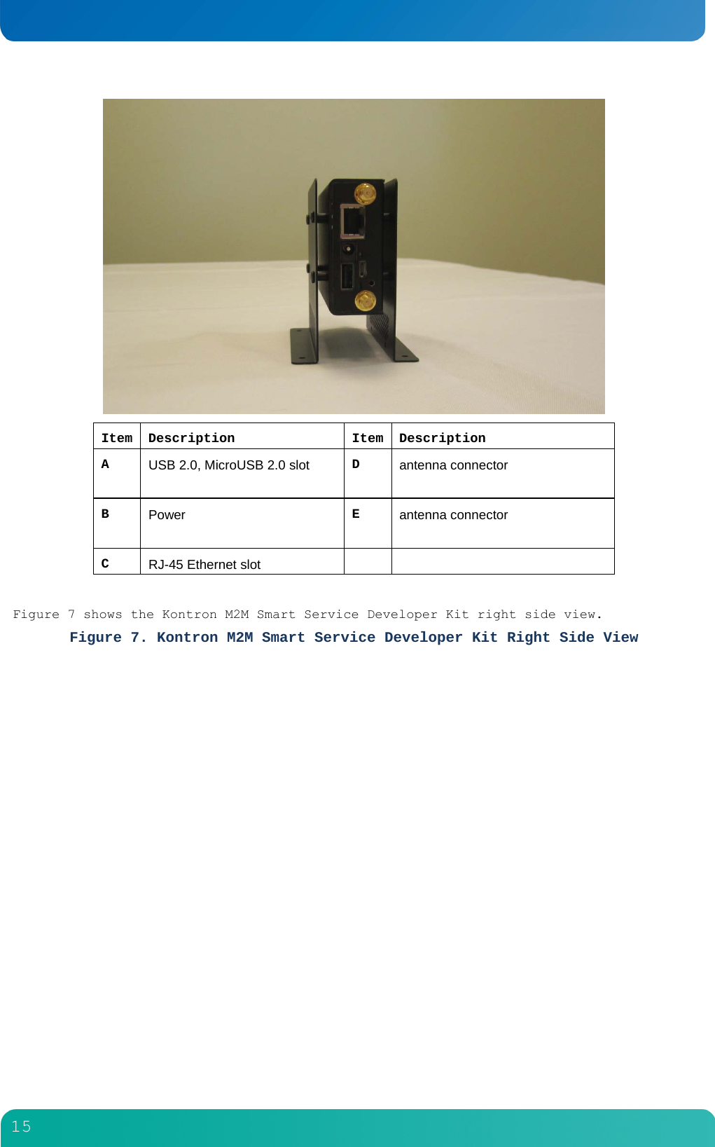
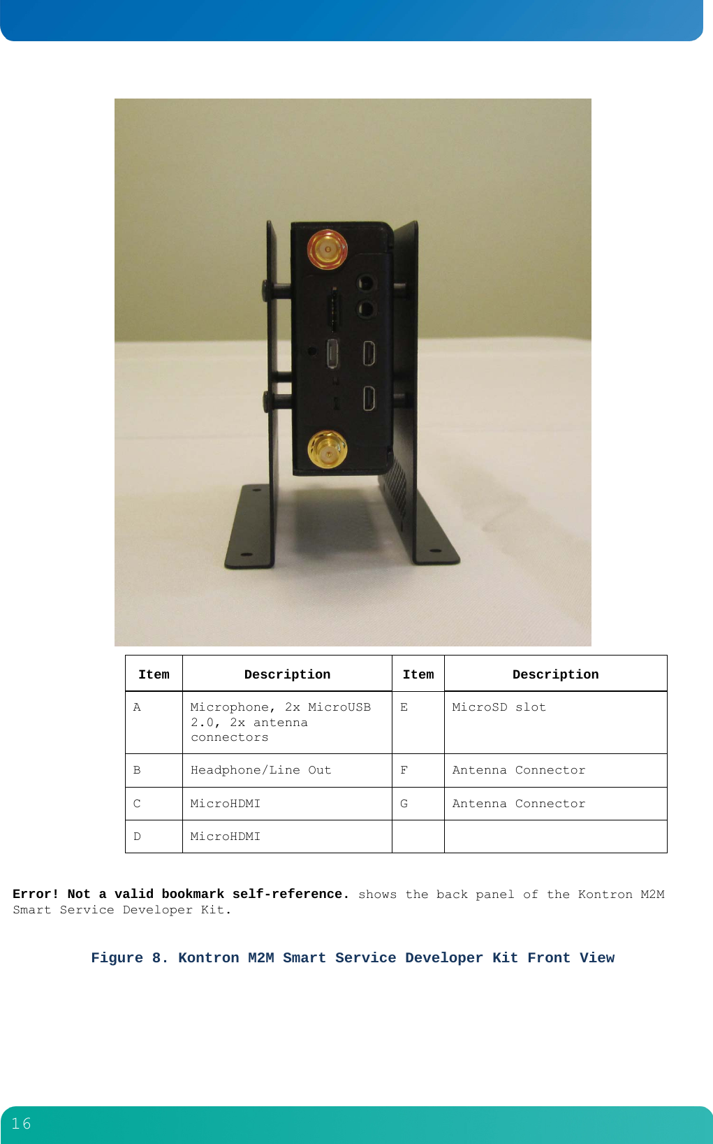
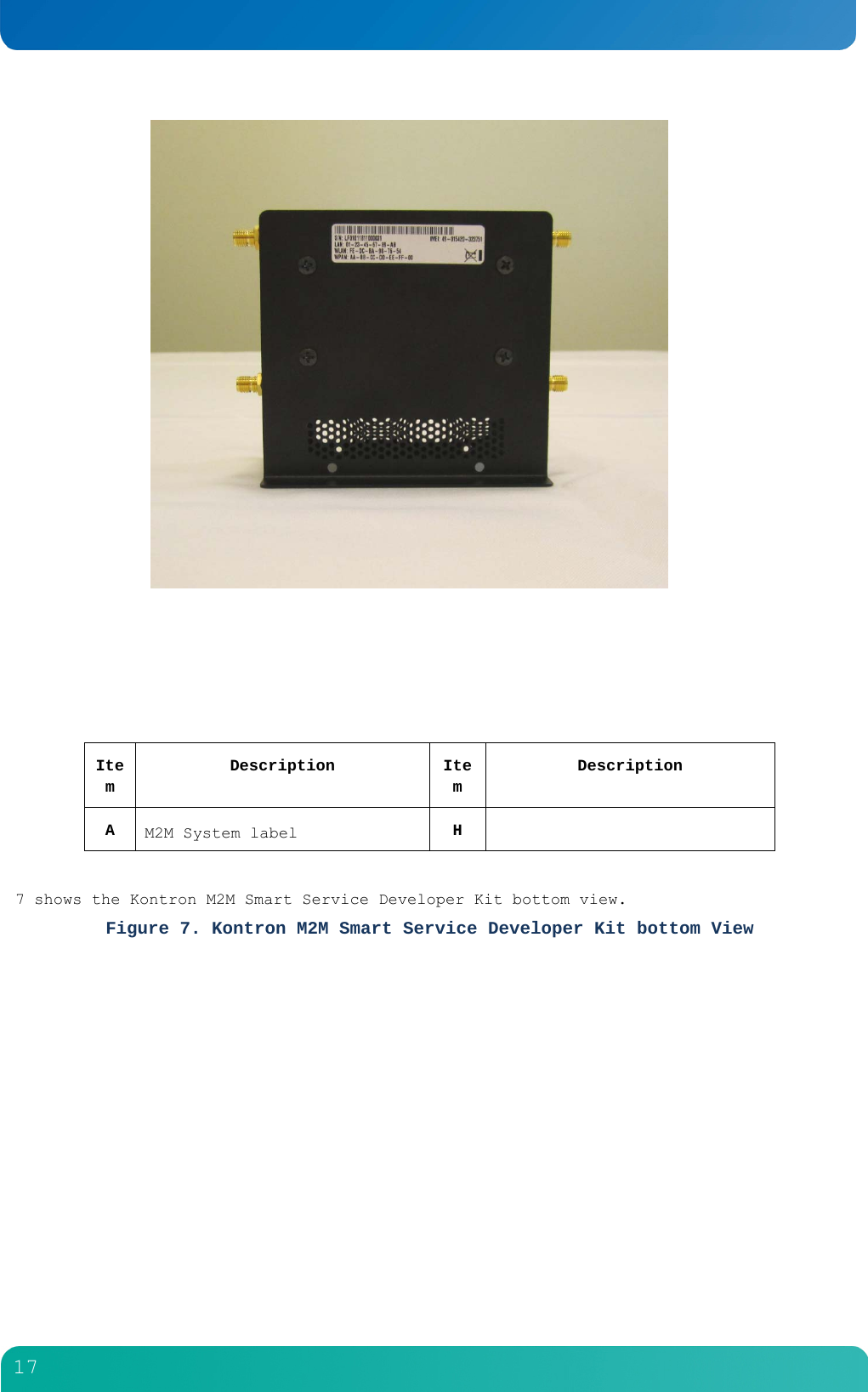
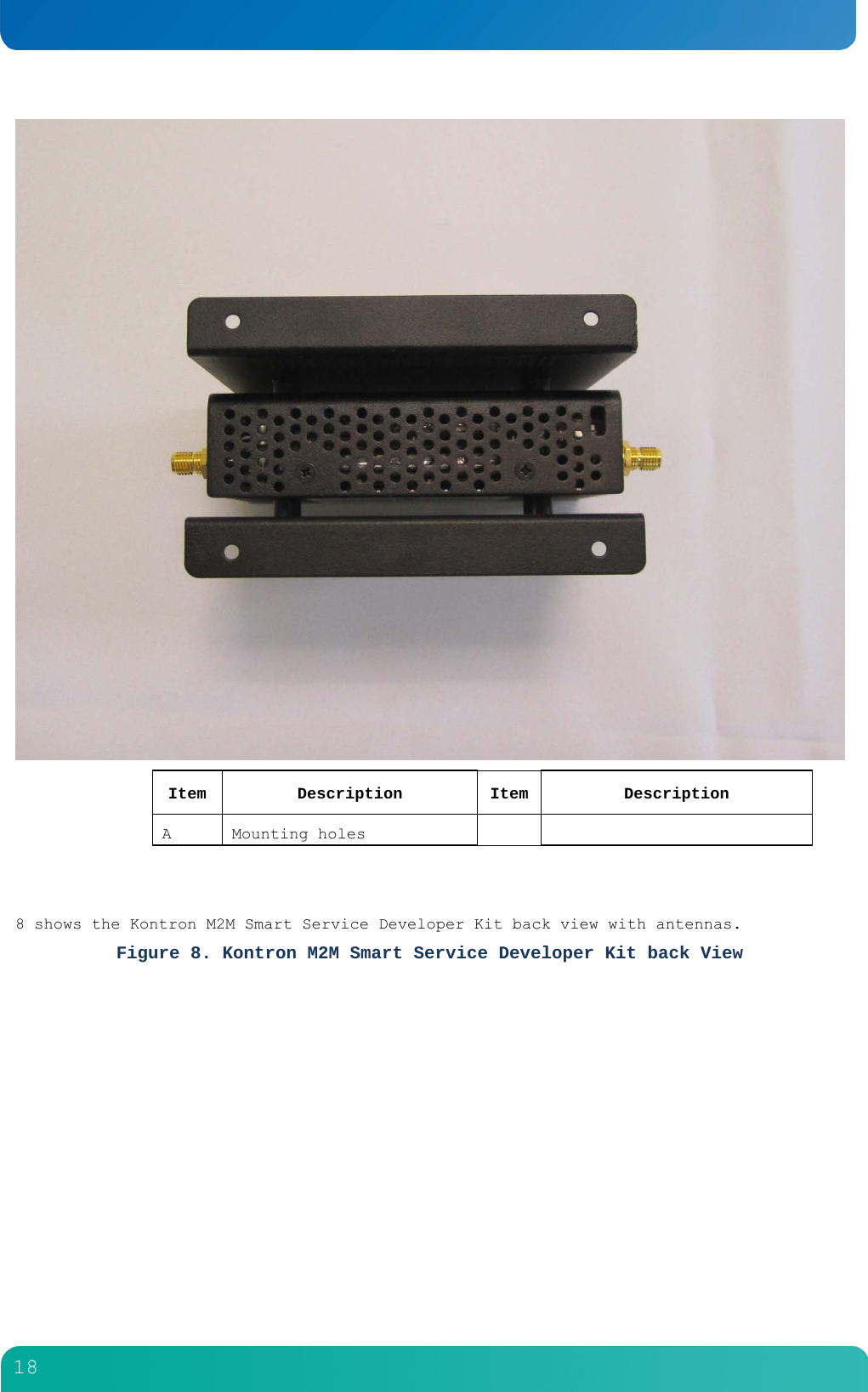
Users manual
Navigation menu
Upload a User Manual
Namespaces
Wiki Guide
HTML
PDF
Info
Views
User Manual
Discussion / Help
Navigation


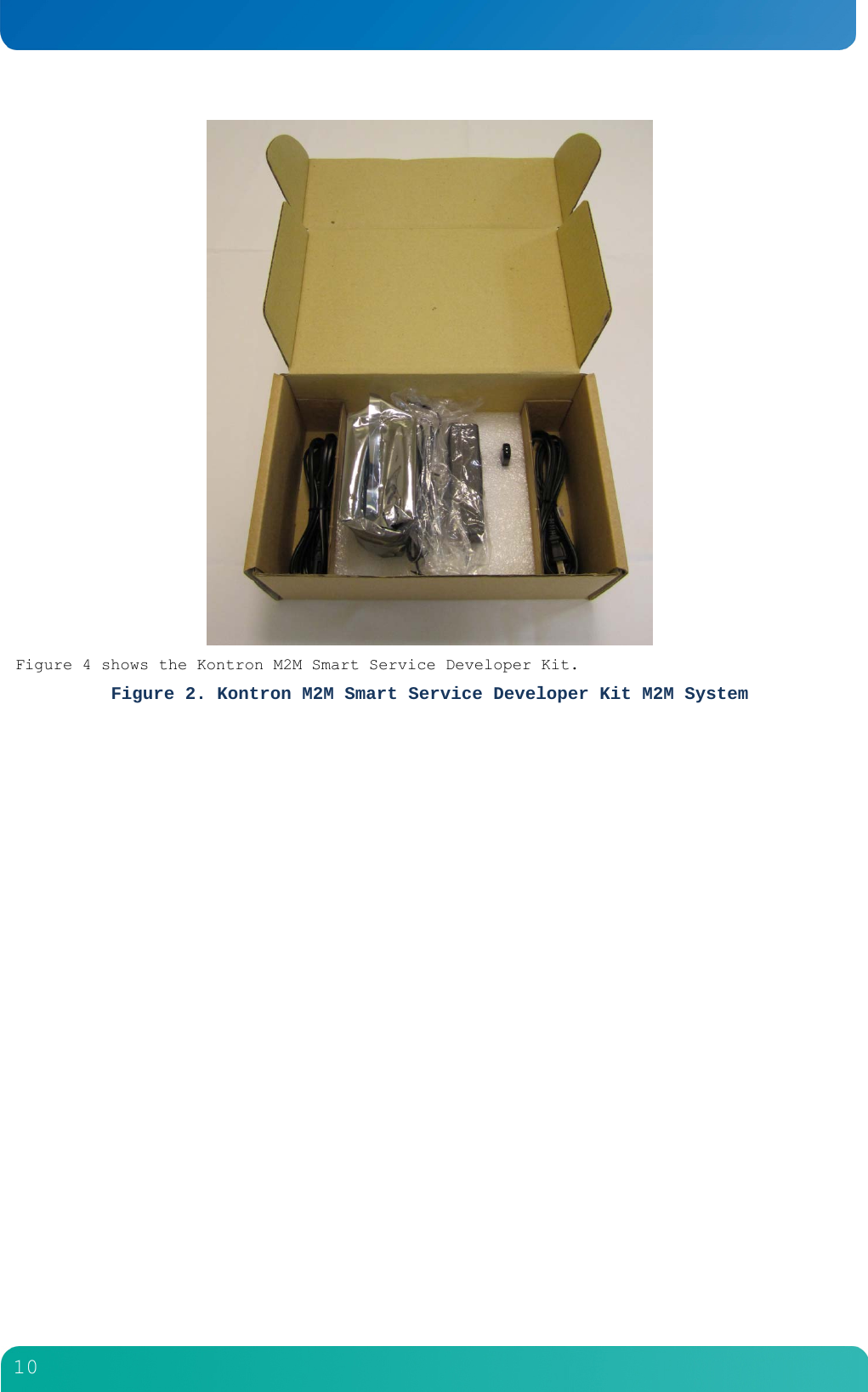

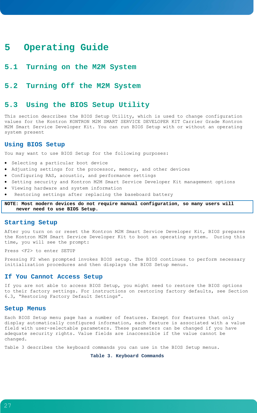
![28 Key Description <F1> Help - Pressing F1 on any menu invokes the general Help window. ← → The left and right arrow keys are used to move between the major menu pages. The keys have no effect if a submenu or pick list is displayed. ↑ Select Item up - The up arrow is used to select the previous value in a menu item’s option list, or a value field pick list. Pressing the Enter key activates the selected item. ↓ Select Item down - The down arrow is used to select the next value in a menu item’s option list, or a value field pick list. Pressing the Enter key activates the selected item. F5/- Change Value - The minus key or the F5 function key is used to change the value of the current item to the previous value. This key scrolls through the values in the associated pick list without displaying the full list. F6/+ Change Value - The plus key or the F6 function key is used to change the value of the current menu item to the next value. This key scrolls through the values in the associated pick list without displaying the full list. On 106-key Japanese keyboards, the plus key has a different scan code than the plus key on the other keyboard, but it has the same effect. <Enter> Execute Command - The Enter key is used to activate submenus when the selected feature is a submenu, or to display a pick list if a selected feature has a value field, or to select a sub-field for multi-valued features like time and date. If a pick list is displayed, the Enter key undoes the pick list and allows another selection in the parent menu. <Esc> Exit - The ESC key provides a mechanism for backing out of any field. This key undoes pressing the Enter key. When the ESC key is pressed while editing a field or selecting menu features, the parent menu is re-entered. When the ESC key is pressed in any submenu, the parent menu is re-entered. When the ESC key is pressed in any major menu, the exit confirmation window is displayed and the user is asked whether changes can be discarded. <F9> Setup Defaults - Pressing F9 causes the following message to appear: Setup Confirmation Load default configuration now? [Yes] [No] If Yes is selected and the Enter key is pressed, all Setup fields are set to their default values. If No is selected and the Enter key is pressed, or if the ESC key is pressed, you are returned to where you were before F9 was pressed without affecting any existing field values.](https://usermanual.wiki/Kontron-America/KM2M800/User-Guide-1559143-Page-29.png)
![29 Key Description <F10> Save and Exit - Pressing F10 causes the following message to appear: Setup Confirmation Save Configuration changes and exit now? [Yes] [No] If Yes is selected and the Enter key is pressed, all changes are saved and Setup is exited. If No is selected and the Enter key is pressed, or the ESC key is pressed, you are returned to where you were before F10 was pressed without affecting any existing values. 5.4 Upgrading the BIOS The upgrade utility lets you upgrade the BIOS in flash memory. The code and data in the upgrade file include the following: On-board system BIOS, including the recovery code BIOS Setup Utility and strings. On-board video BIOS, SCSI BIOS, and other option ROMs for devices embedded on the Kontron M2M Smart Service Developer Kit board. OEM binary area Microcode Splash Screen Preparing for the Upgrade The steps below explain how to prepare to upgrade the BIOS, including how to record the current BIOS settings and how to obtain the upgrade utility. NOTE: In the unlikely event that a BIOS error occurs during the BIOS update process, a recovery process may need to be followed to return the system to service. See Section 1.4, “Additional Information and Software” for additional information. Obtaining the Upgrade Download the BIOS image file to a temporary folder on your hard drive. See Section 1.4, “Additional Information and Software” for more information. Note: Review the instructions and release notes that are provided in the readme file distributed with the BIOS image file before attempting a BIOS upgrade. The release notes contain critical information regarding jumper settings, specific fixes, or other information to complete the upgrade. Updating the BIOS Follow the instructions in the readme file that came with the BIOS upgrade. When the update completes, remove the bootable media from which you performed the upgrade. Note: Do not power down the system during the BIOS update process!](https://usermanual.wiki/Kontron-America/KM2M800/User-Guide-1559143-Page-30.png)