Korea Data Systems Co KDT-3861 Personal Computer User Manual G P cont p65
Korea Data Systems Co Ltd Personal Computer G P cont p65
UserManual.wiki
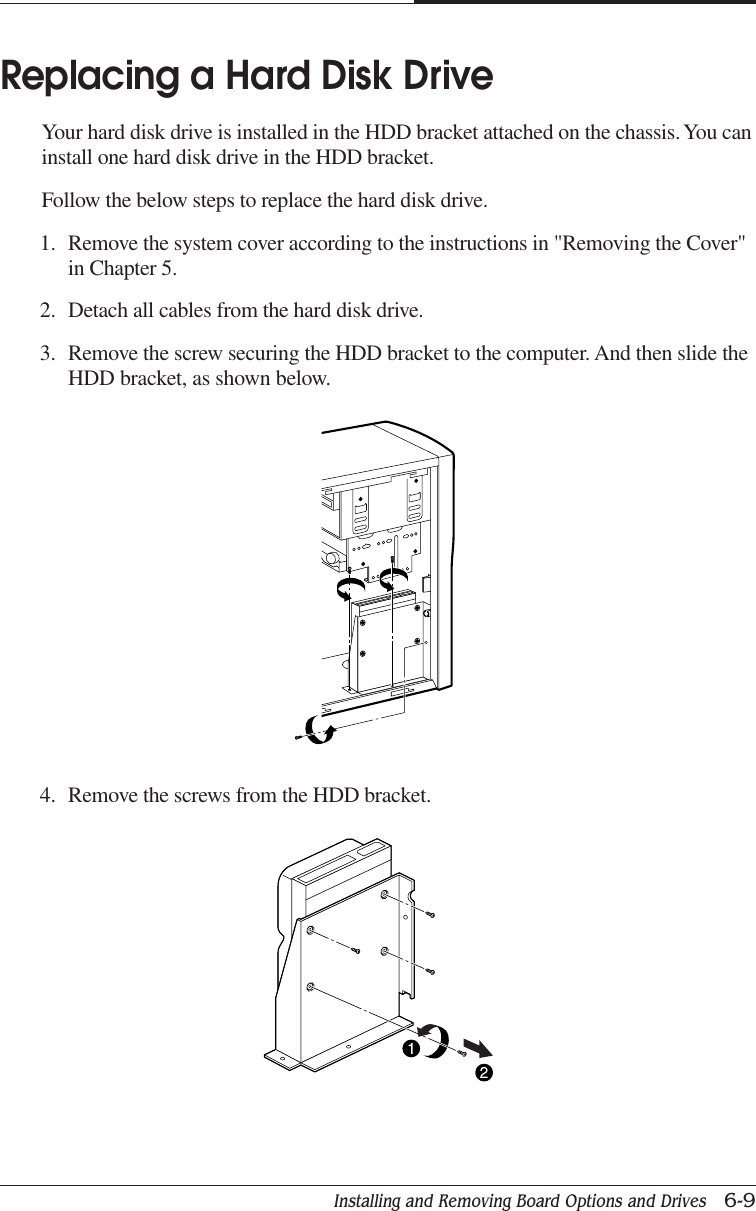
>
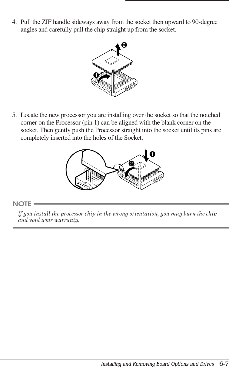
Korea Data Systems Co
>
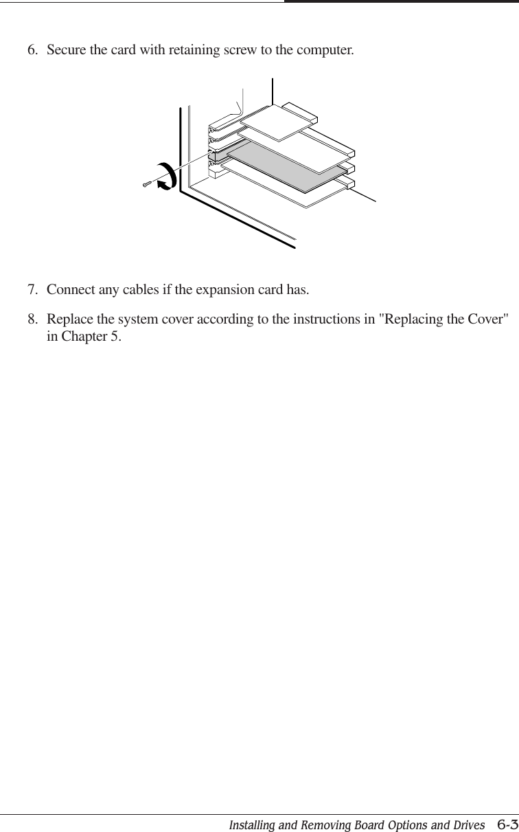
KDT 3861 User Manual
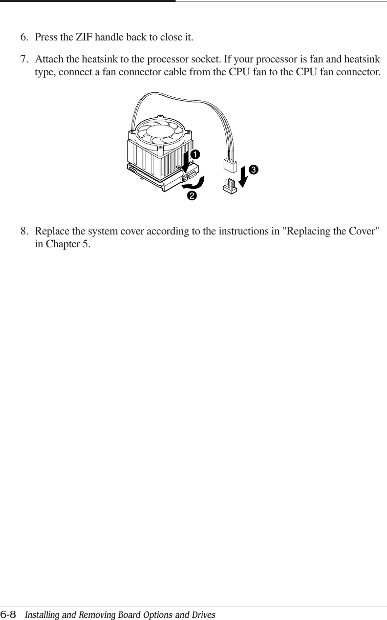
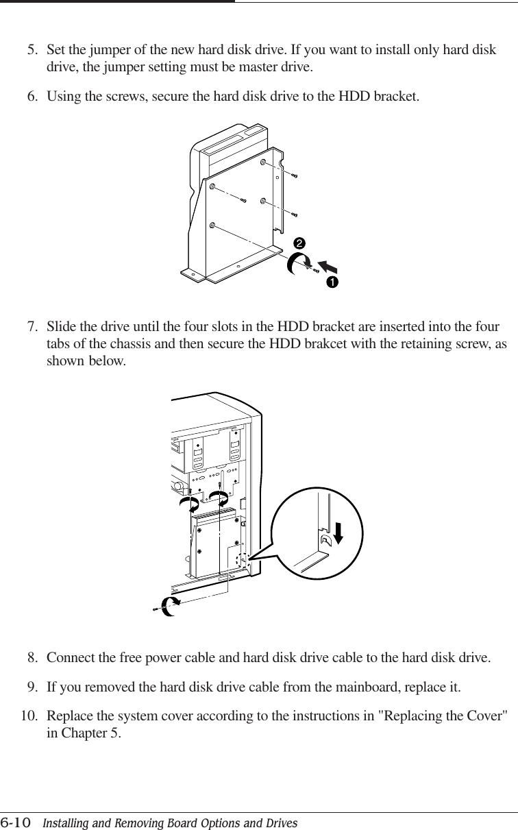
users manual
Navigation menu
Upload a User Manual
Namespaces
Wiki Guide
HTML
PDF
Info
Views
User Manual
Discussion / Help
Navigation
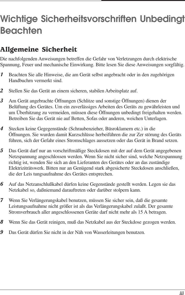
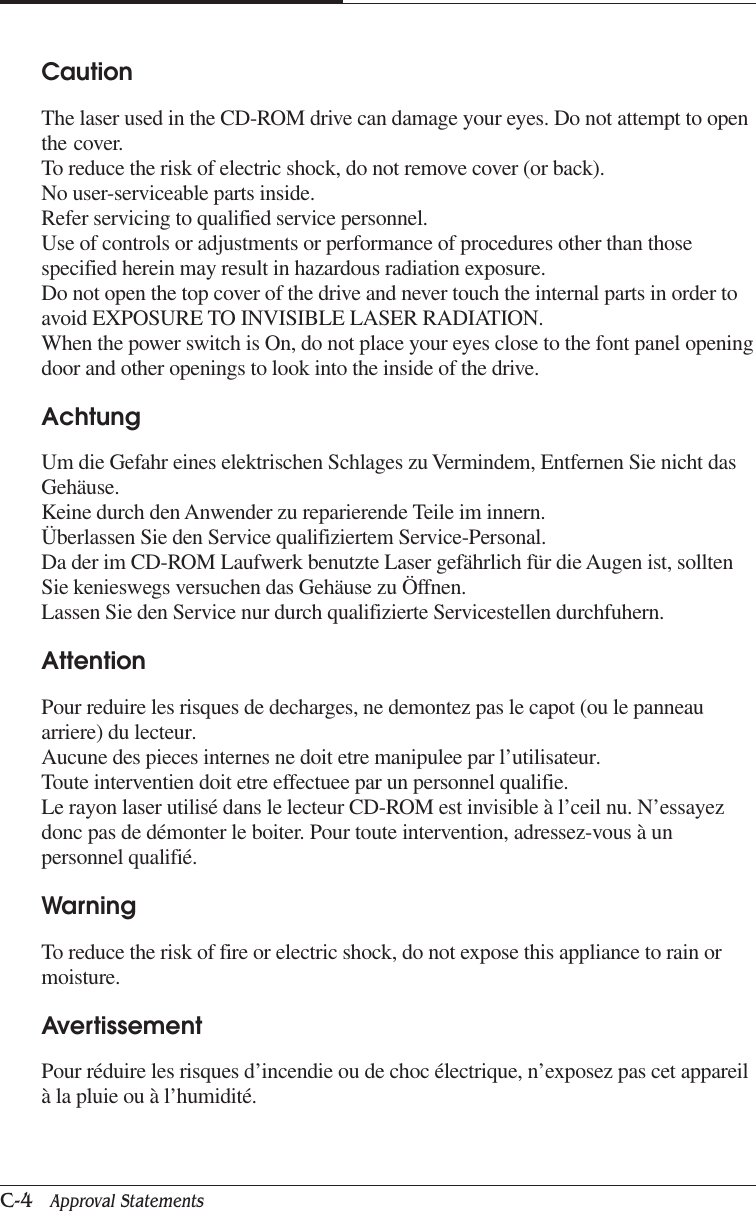
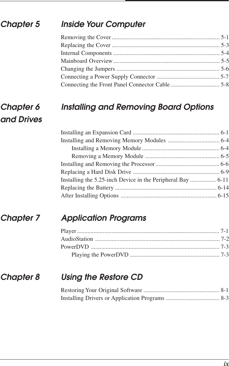
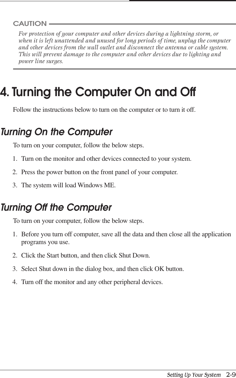
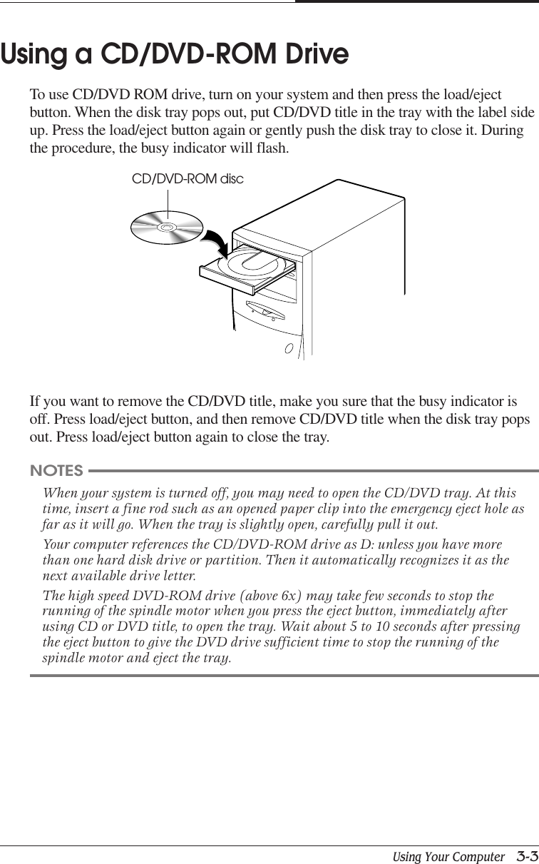
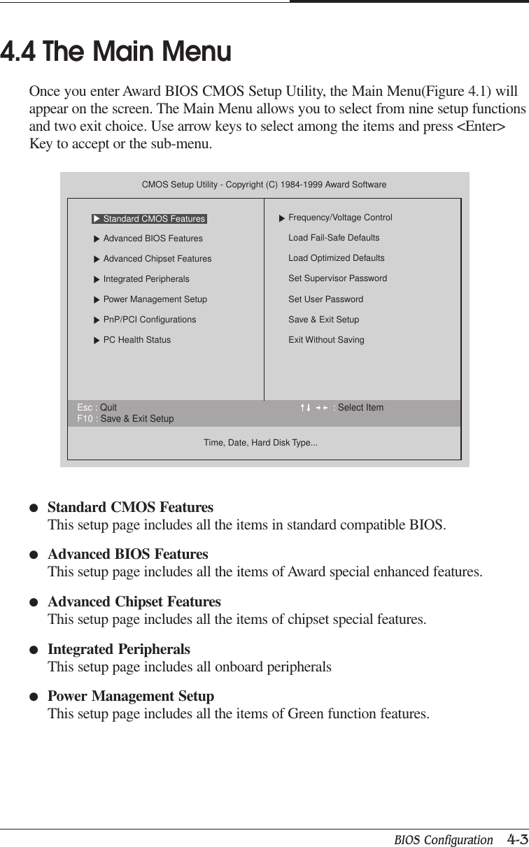
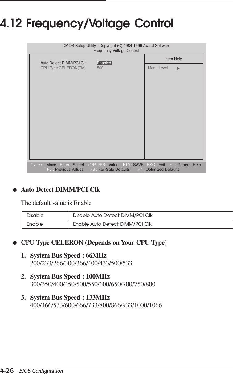
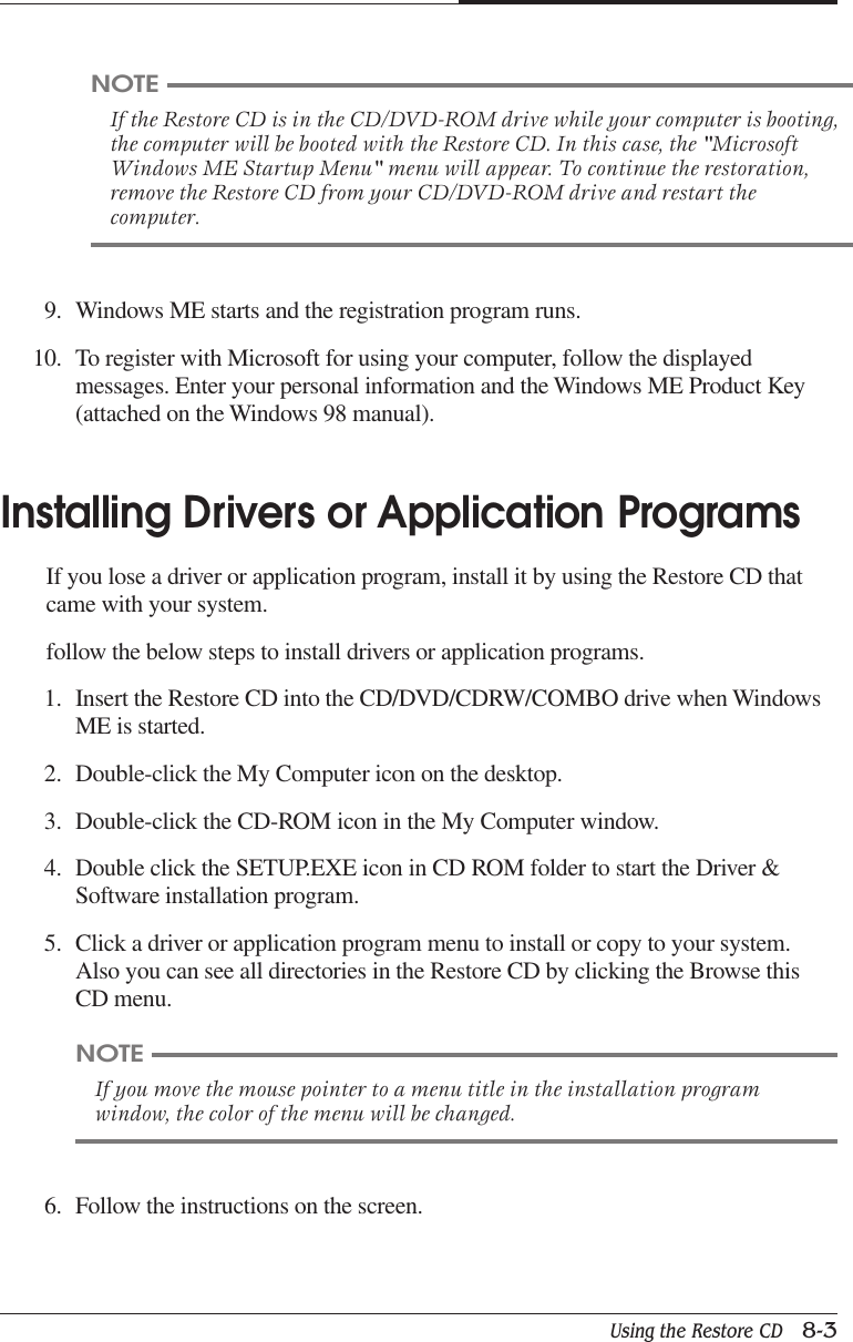
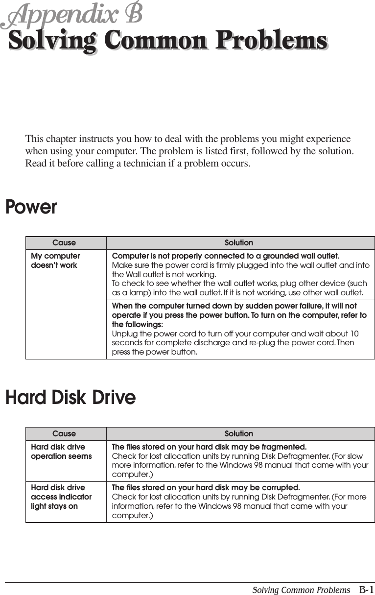
![ivWartung Des ComputersWenn der Computer nicht ordnungsgemäß arbeitet, dürfen Sie nur die Einstellungenvornehmen, die im Handbuch genannt werden. Andere Einstellungen oder Verän derungenkönnen den Computer beschädigen oder zerstören. Umfangreiche und kostspieligeReparaturen würden notwendig werden, um das Gerät wieder betriebsfähig zu machen.Ziehen Sie den Netzstecker aus der Steckdose und verständigen Sie den zuständigenKundendienst bei folgenden Storungen:ANetzkabel ist defekt oder strak abgenutzt.BFlüssigkeit ist in das Gerät geschüttet worden.CDas Gerät war Regen oder Leitungswasser aus-gesetzt.DDas Gerät ist heruntergefallen oder das Gehäuse ist beschädigt.EDas Gerät arbeitet nicht mehr richtig.AchtungWenn Sie das Gerät Öffnen müssen (Abnahme der verschraubten Haube), ist unbedingtfolgendes zu beachten:ADas Netzkabel muß aus der Steckdose gezogen werden und zwar bevor Sie das GerätÖffnen.BDie Haube muß wieder monitiert und verschraubt werden. Erst dann darf das Netzkabelwieder eingesteckt werden.Safety InstructionEnsure that the appropriate power cord is supplied with personal computer. If the power cordis not supplied with personal computer, use the correct listed cord sets as below:Rating125V, 10A Min.18AWG/3250V, 6A Min.18AWG/3TypeSVTMAX. 4.5mlongSVTMax. 4.5mlongOne end terminated with molded on cordconnector body.Attachment plug cap with a nama 5-15P.One end terminated with molded on cordconnector body.]Attachment plug cap with a nama 6-15P.Note](https://usermanual.wiki/Korea-Data-Systems-Co/KDT-3861/User-Guide-135777-Page-4.png)
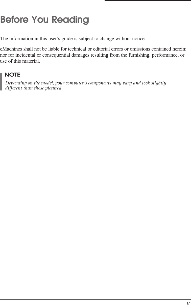

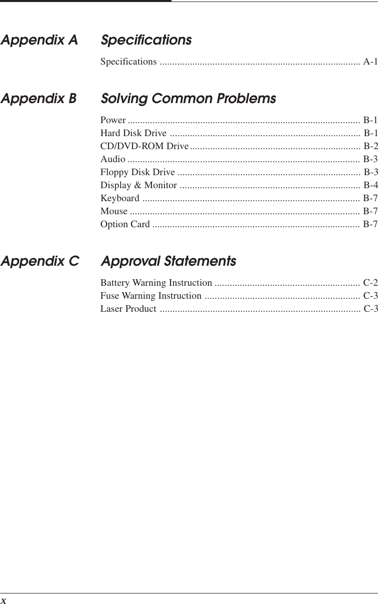
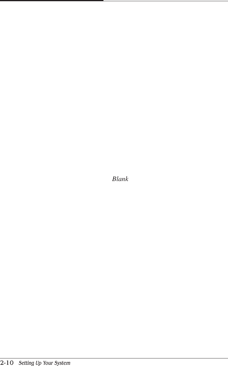
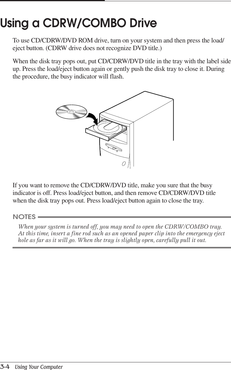
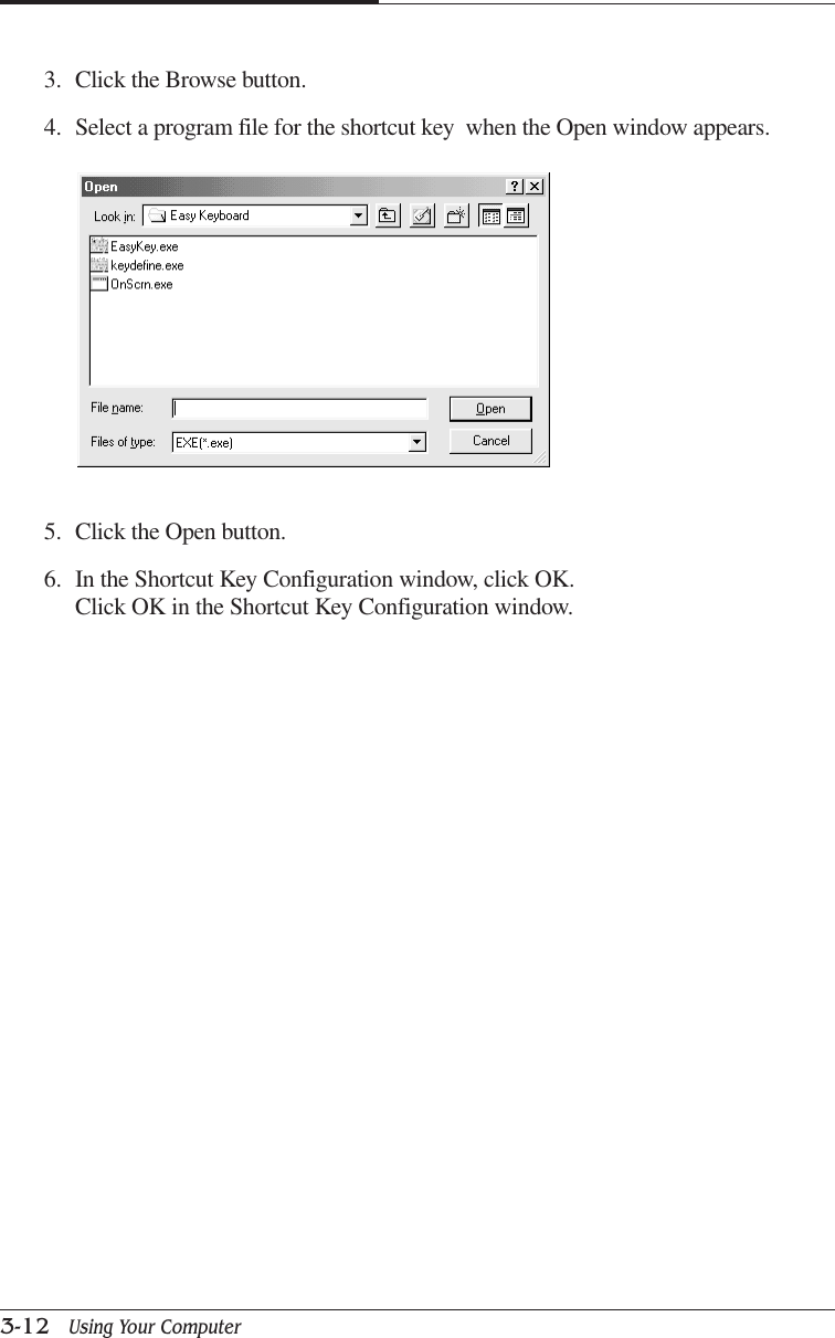
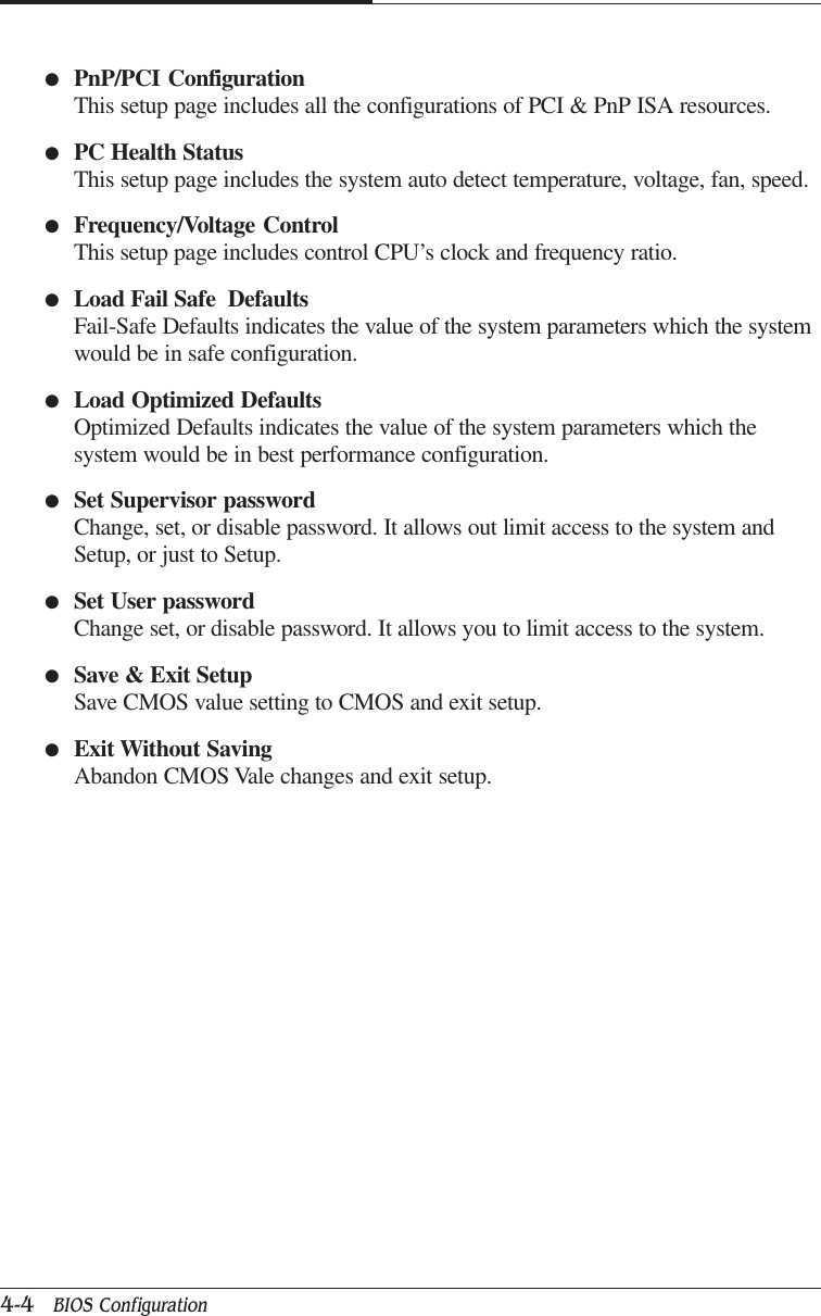
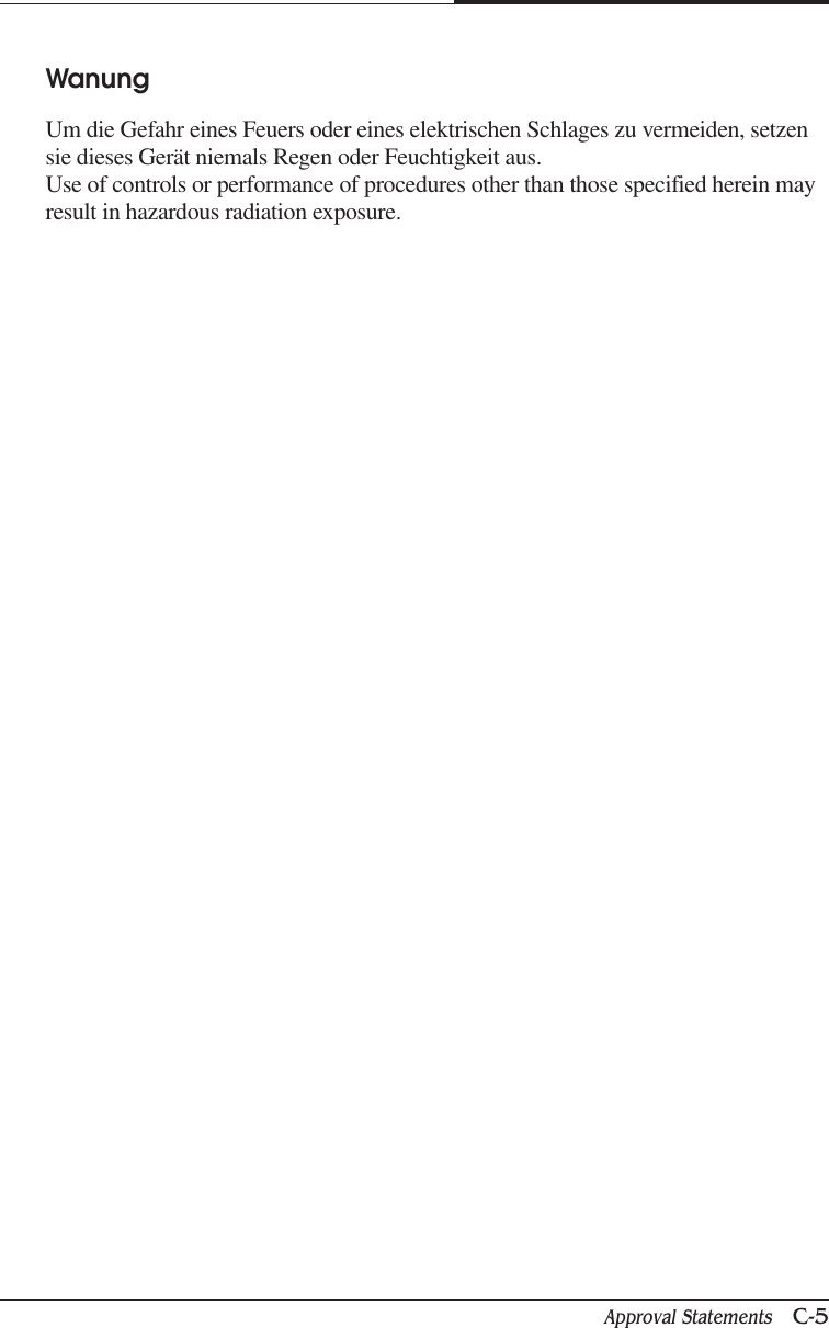
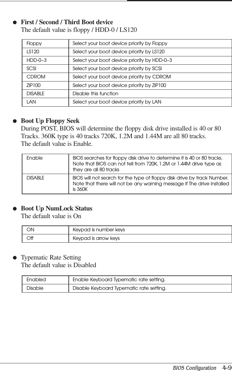
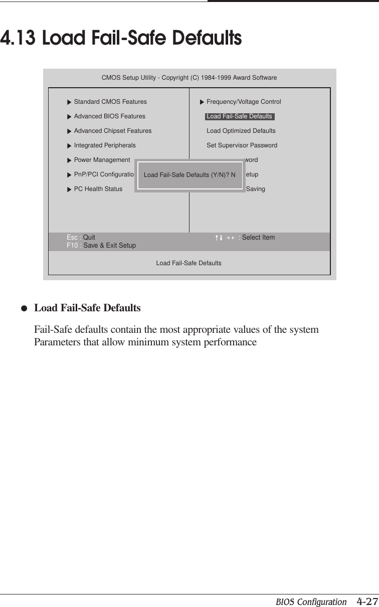
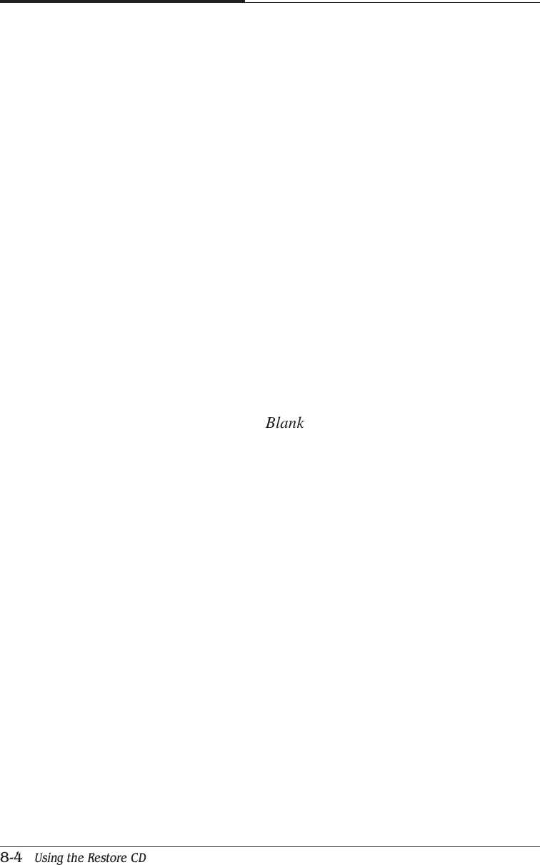
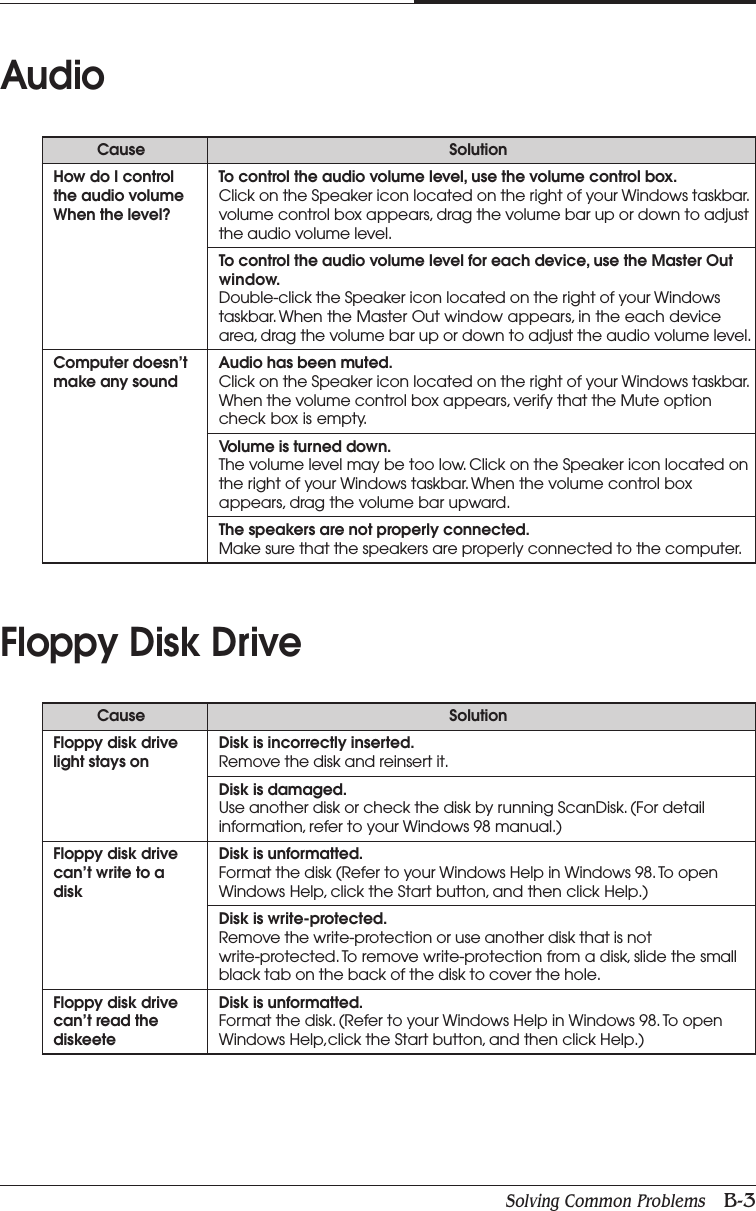
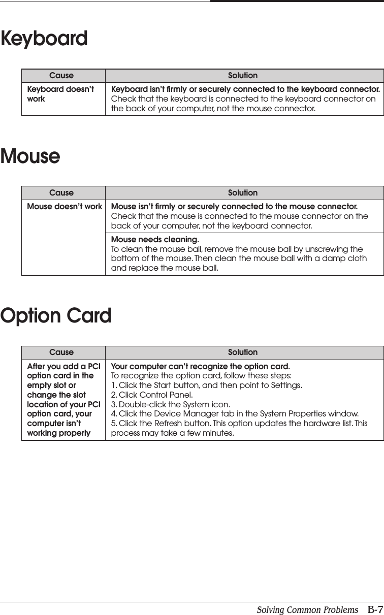
![CHAPTER 44-8 BIOS Configuration●Virus WarningIf it is set to enable, the category will flash on the screen when there is anyattempt to write to the boot Sector or partition table of the hard disk driver.The system will halt and the following error message will appear in the meantime.You can run anti-virus program to locate the problem.4.6 Advanced BIOS FeaturesEnable Activate automatically when the system boots up causing a Warningmessage to appear when anything attempts to Access the boot sectoror hard disk partition tableDisable No warning message to appear when anything attempts to Access theboot sector or hard disk partition table:Move Enter : Select +/-/PU/PB : Value F10 : SAVE ESC : Exit F1 : General HelpF5 : Previous Values F6 : Fail-Safe Defaults F7 : Optimized DefaultsCMOS Setup Utility - Copyright (C) 1984-1999 Award SoftwareAdvanced BIOS FeaturesVirus WarningFirst Boot Device CDROMSecond Boot Device FloppyThird Boot Device HDD-0Boot Up Floppy Seek EnabledBoot Up NumLock Status OnTypematic Rate Setting DisabledTypematic Rate [Chars/Sec] 6Typematic Delay [Msec] 250Security Option SetupHDD S.M.A.R.T. Capabillity DisabledReport No FDD For WIN 95 NoItem HelpMenu Level Allows you to choosethe VIRUS warningfeature for IDE Hard Disk boot sectorprotection. If thisfunction is emabledand someone attempt towrite date into thisarea, BIOS will show awarning message onscreen and alarm beepDisabled](https://usermanual.wiki/Korea-Data-Systems-Co/KDT-3861/User-Guide-135777-Page-50.png)
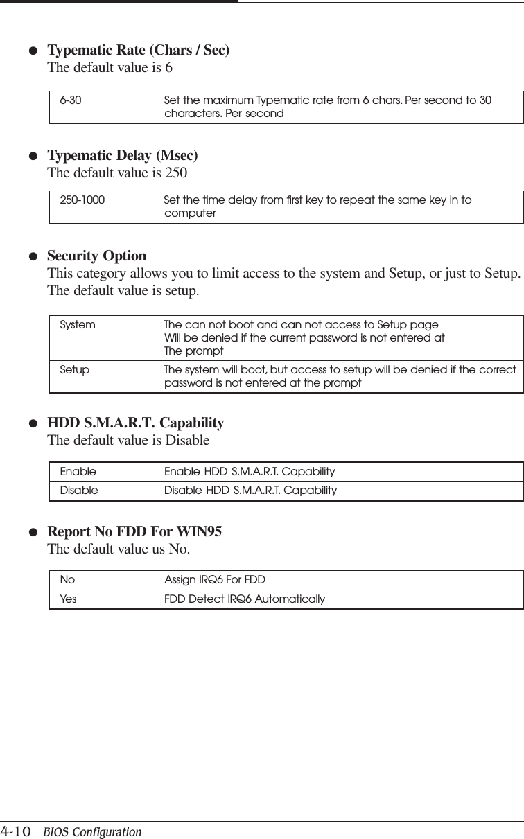
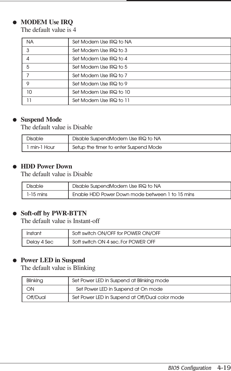
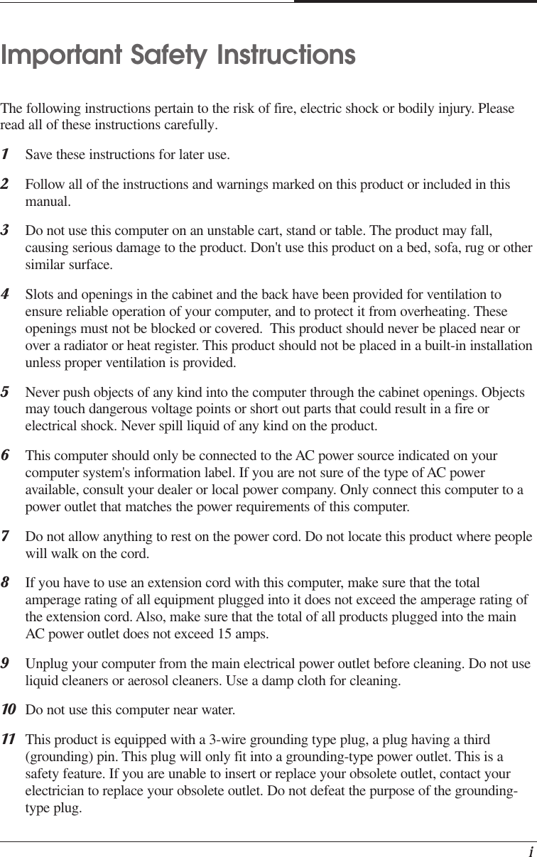
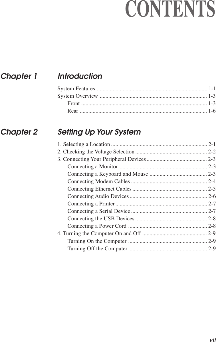
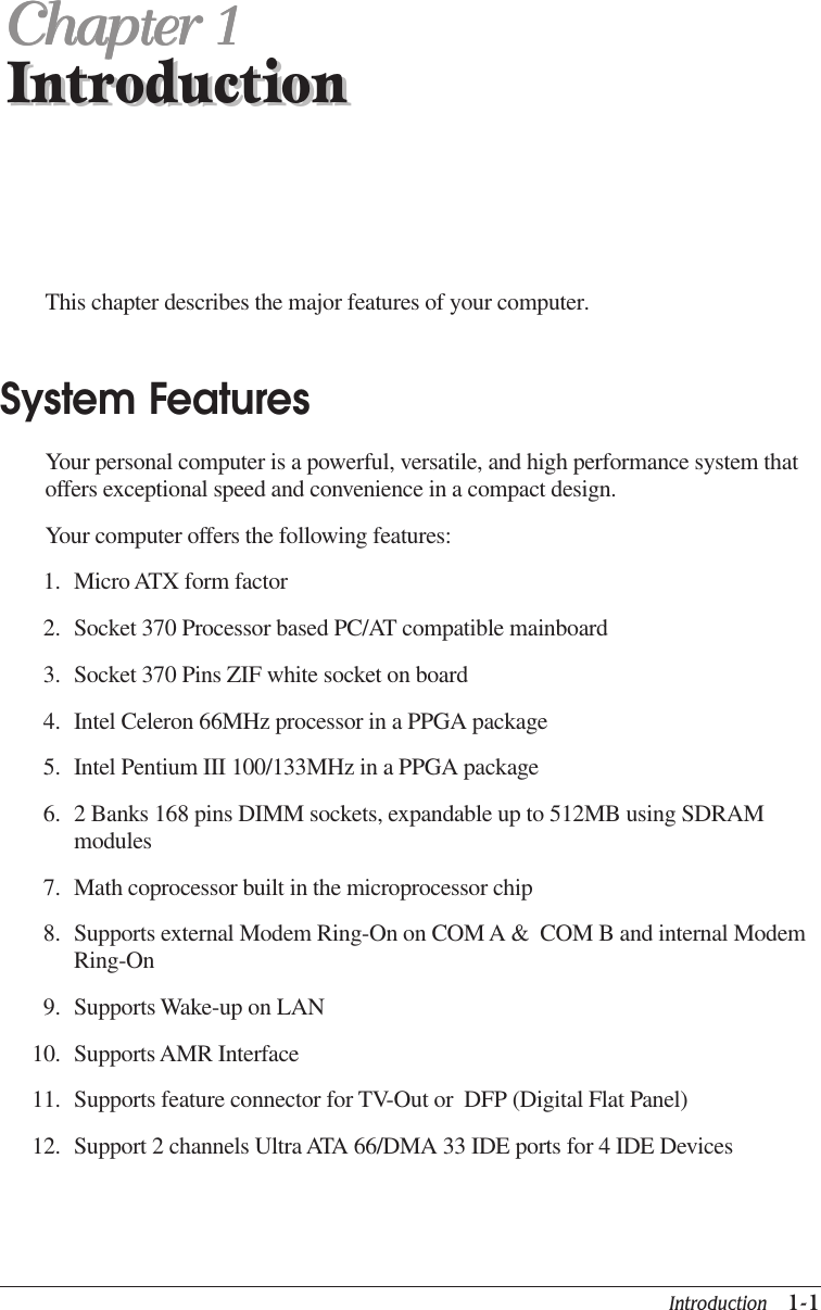
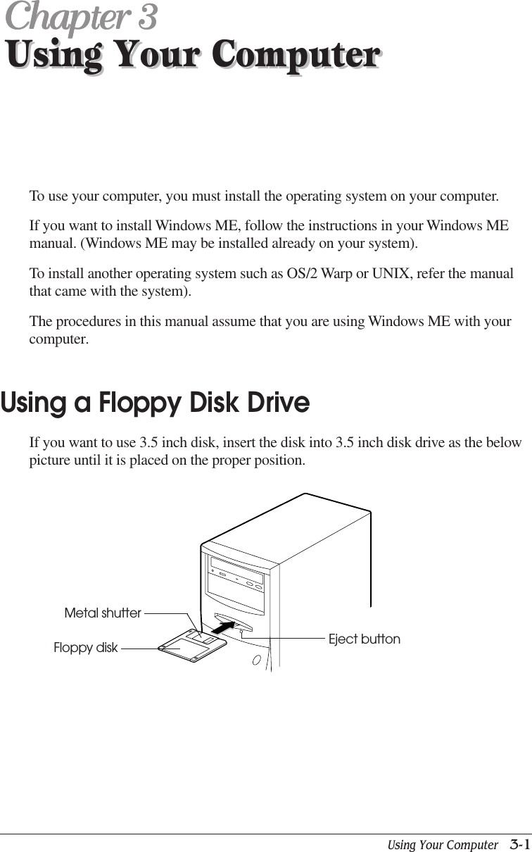
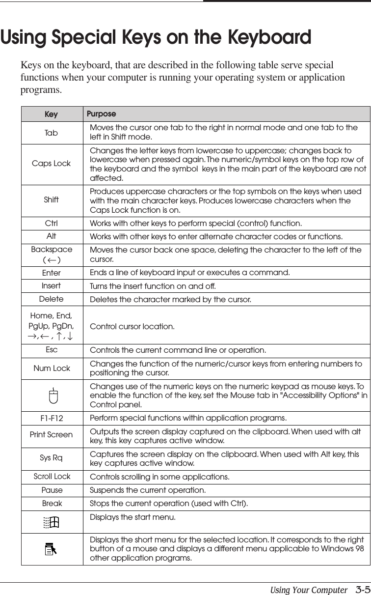
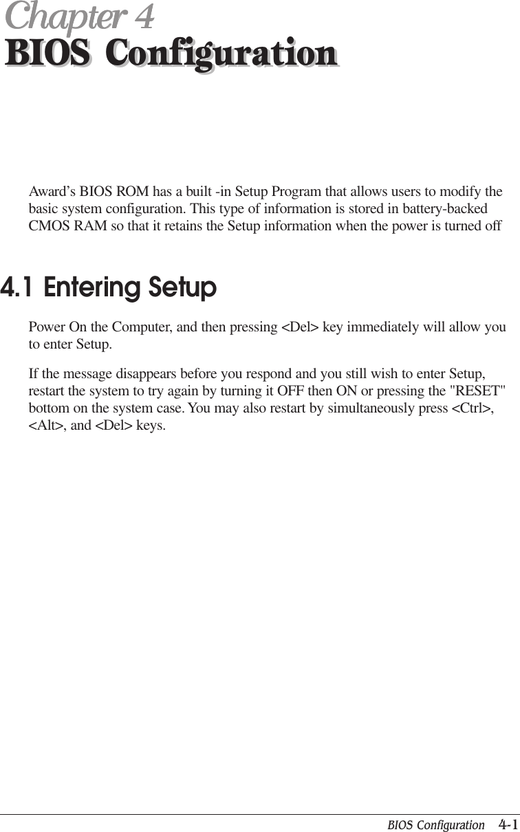
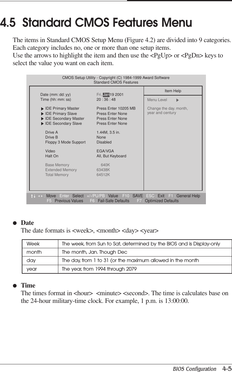
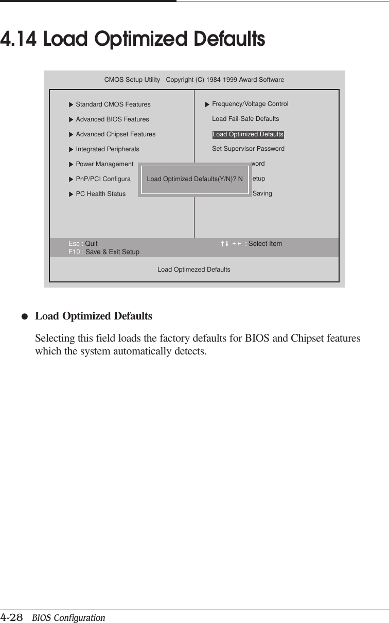
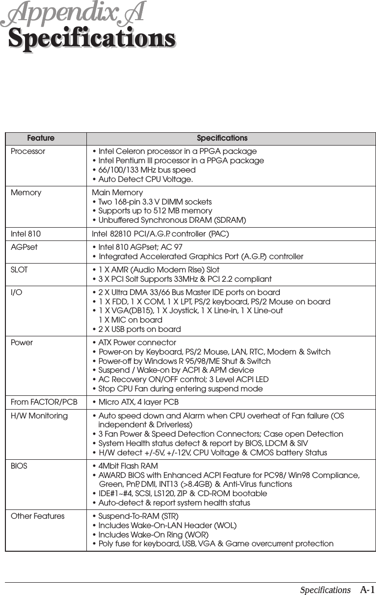
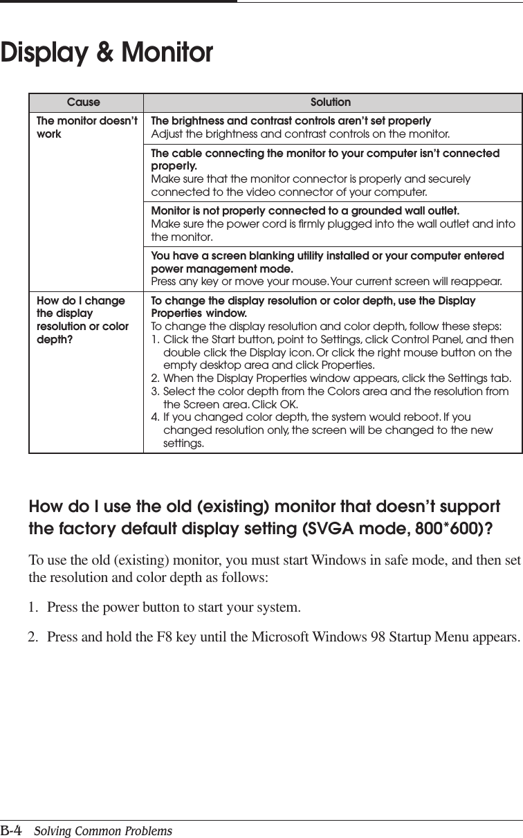
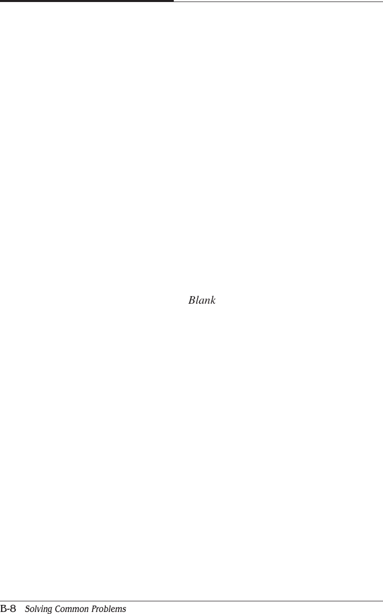
![BIOS Configuration 4-21CHAPTER 4●Resume by AlarmThe default value is DisabledIF the default value is Enabled● Primary IDE 0/1 The default value is Disabled● Secondary IDE 0/1 The default value is Disabled● FDC/COM/LPT Port The default value is Enabled● PCI RIRQ [A-D] # The default value is EnabledDisable Disable this functionEnabled Enable alarm function to POWER ON systemData (of Month) Alarm 0-31Time (hh:mm:ss) Alarm (0-23) : (0-59) : (0-59)Disable Disable this functionEnabled Enable monitor Primary IDE 0/1 for Green event.Disable Disable this functionEnabled Enable monitor Secondary IDE 0/1 for Green event.Disable Disable this functionEnabled Enable monitor FDC/COM/LPT for Green event.Disable Monitor PCI PIRQ [A-D] IRQ ActiveEnabled Ignore PCI PIRT [A-D] IRQ Active](https://usermanual.wiki/Korea-Data-Systems-Co/KDT-3861/User-Guide-135777-Page-63.png)
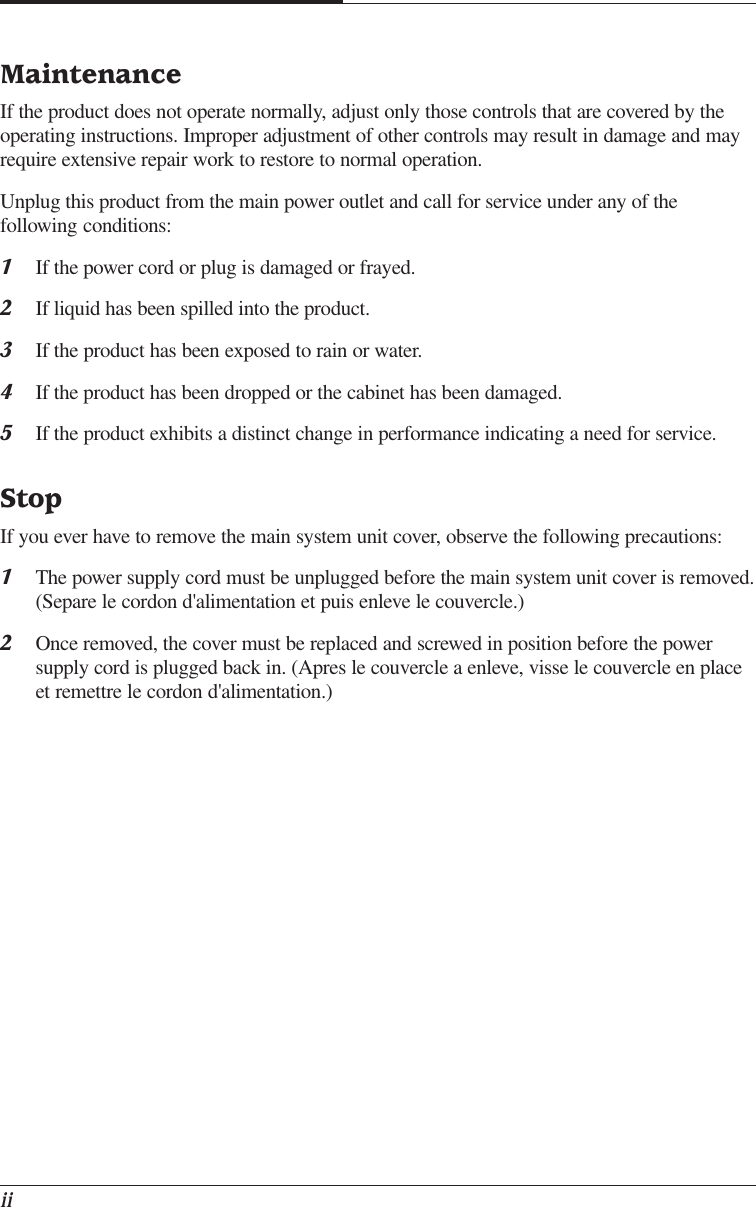
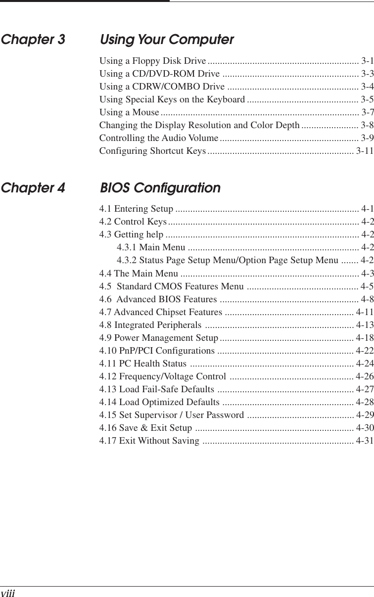
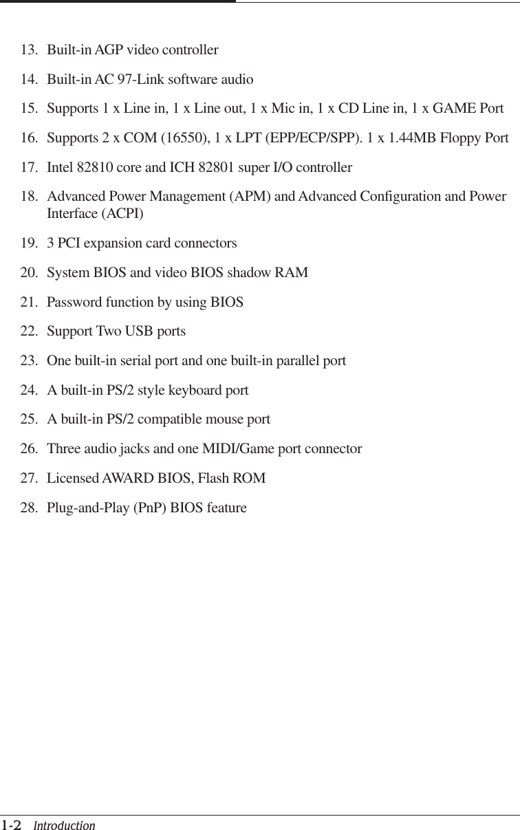
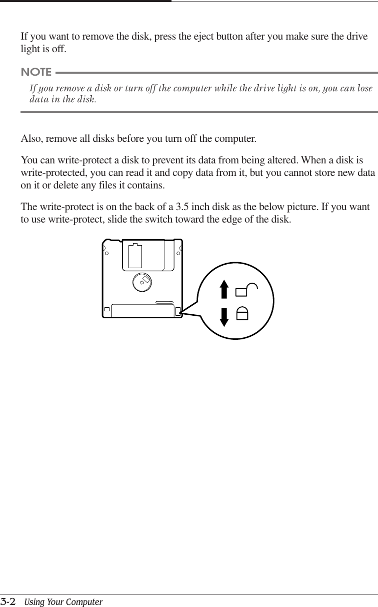
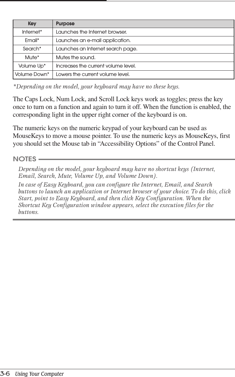
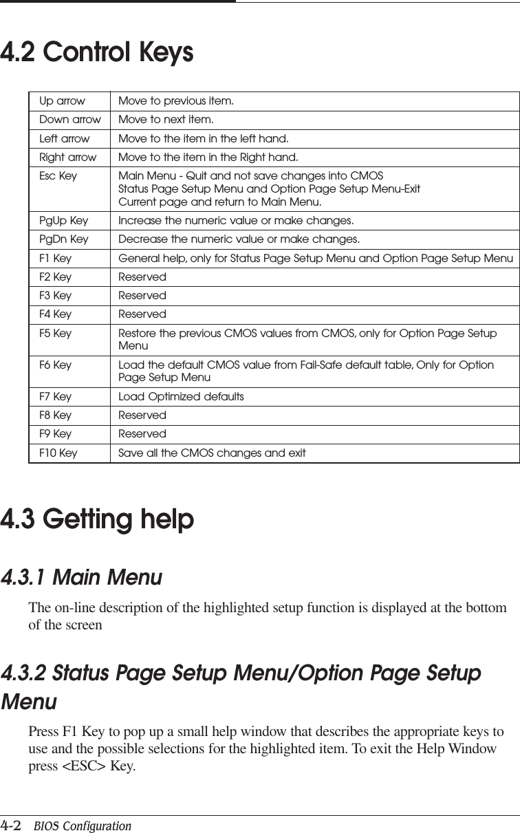
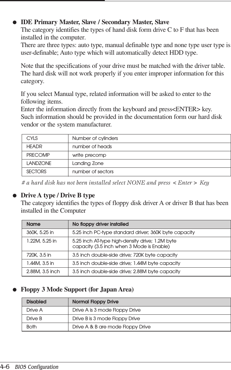
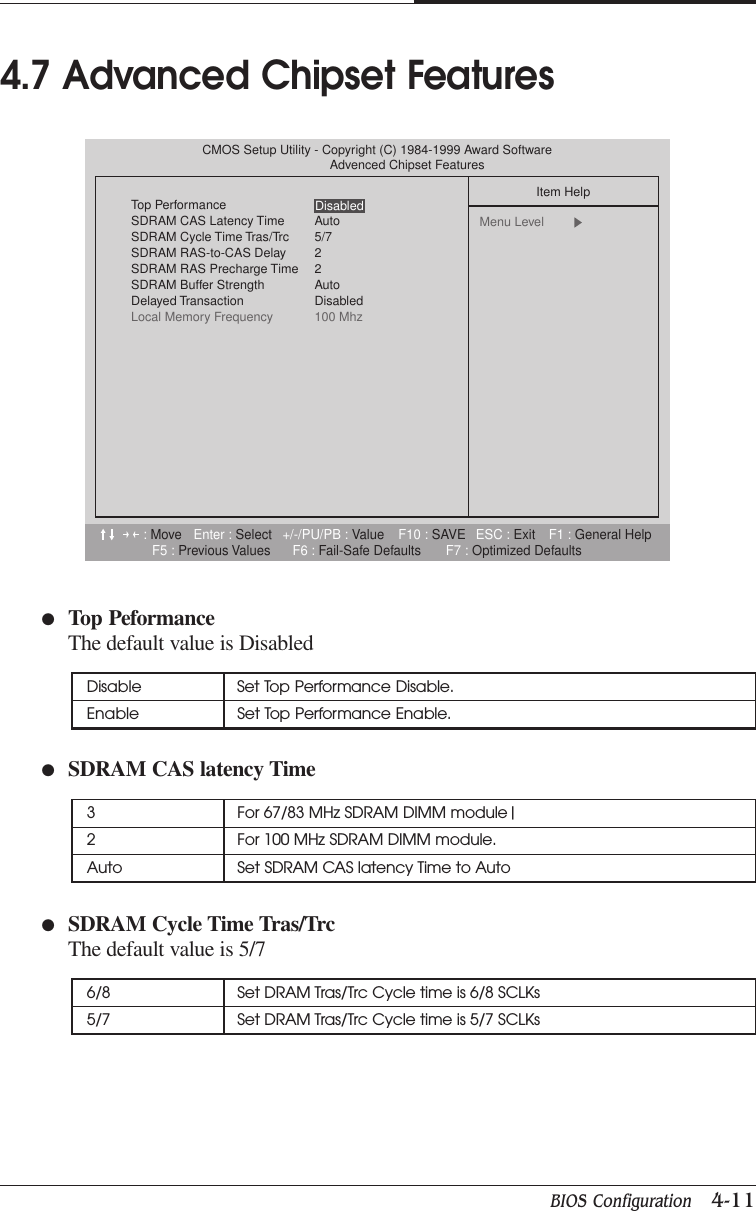
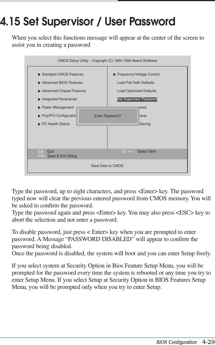
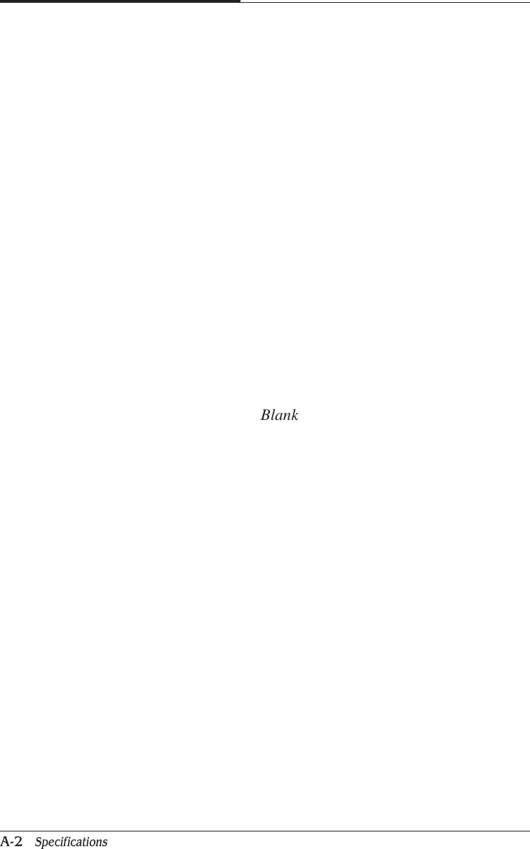
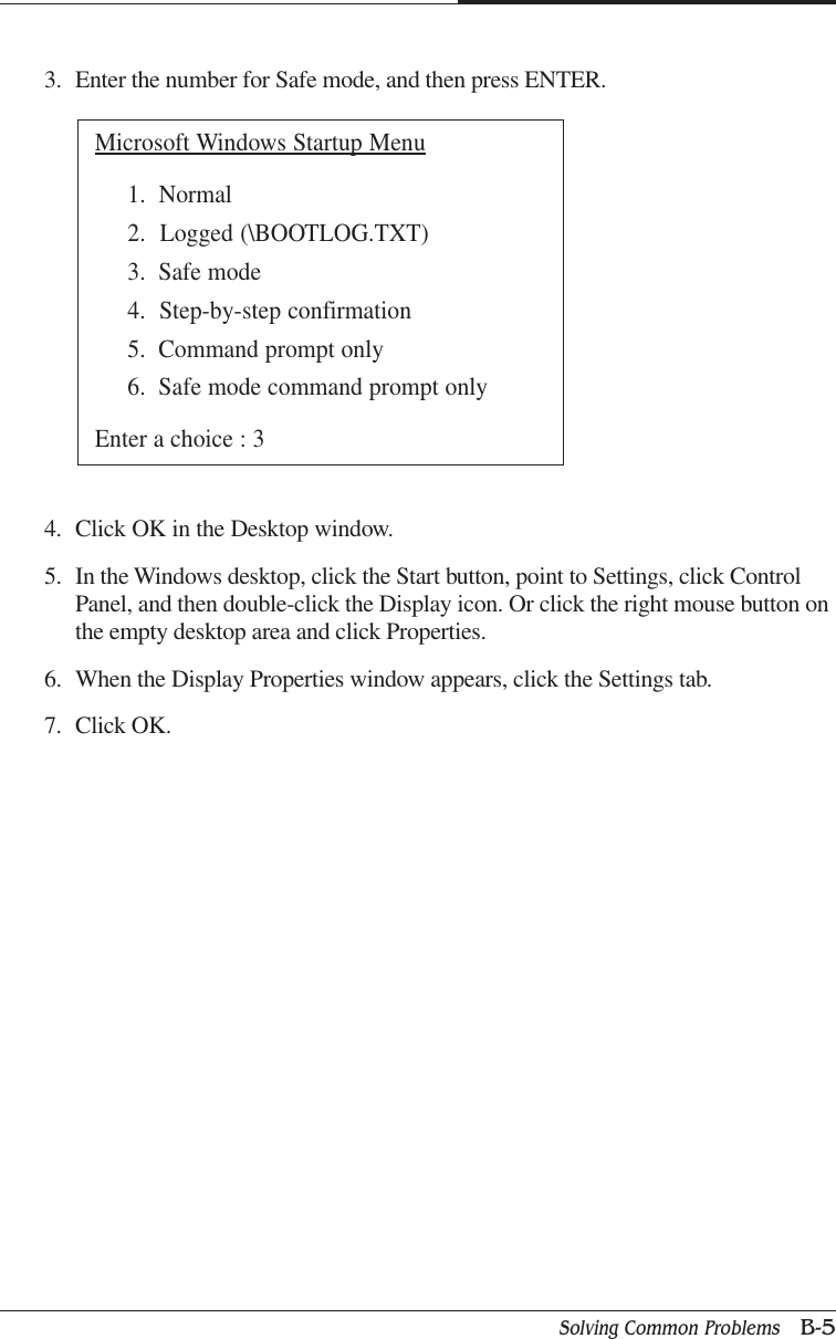
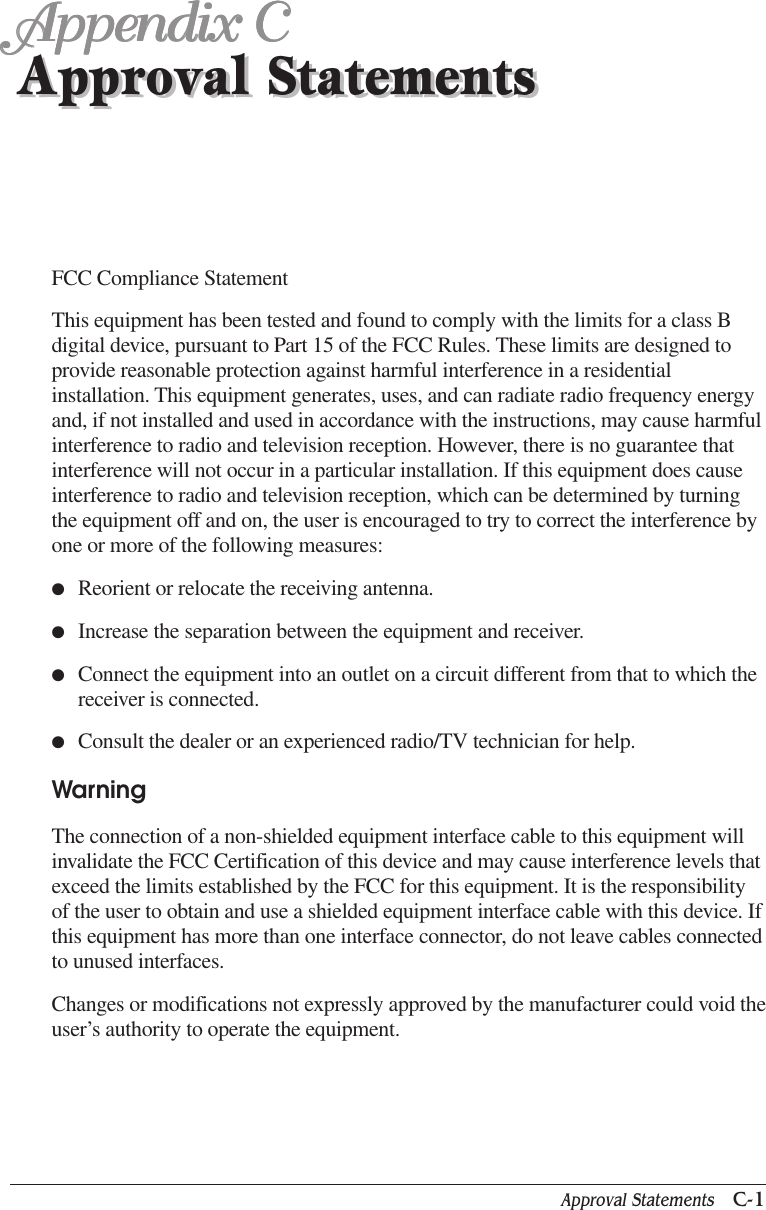
![CHAPTER 44-22 BIOS Configuration● PNP OS Installed The default value is No● Reset Configuration Data The default value is Disable4.10 PnP/PCI ConfigurationsYes Enable PNP OS Installed functionNo Disable PNP OS Installed functionDisable Disable this functionESCD Enable clear PNP information in ESCDDMI Reset Configuration Data in DMIBOTH Reset Configuration Data DMI & ESCD:Move Enter : Select +/-/PU/PB : Value F10 : SAVE ESC : Exit F1 : General HelpF5 : Previous Values F6 : Fail-Safe Defaults F7 : Optimized DefaultsCMOS Setup Utility - Copyright (C) 1984-1999 Award SoftwarePnP/PCI ConfigurationsPNP OS InstalledReset Configuration Data DisabledResources Controlled By Auto [ESCD]IRQ Resoarces Press EnterDMA Resoarces Press EnterPCI/VGA Palette Snoop DisabledItem HelpMenu Level Select yes if you are using a plug and playcapable operatingsystem Select Mo ifyou need the BIOS to configure non-bootdevicesNo](https://usermanual.wiki/Korea-Data-Systems-Co/KDT-3861/User-Guide-135777-Page-64.png)

![APPENDIX BB-2 Solving Common ProblemsCause SolutionThe CD/DVD-ROM CD/DVD is not properly seated in the CD/DVD-ROM drive.drive cannot read Eject the CD/DVD, gently but firmly press down on the CD/DVD to seatCD/DVD it in the drive, then reload.Your CD/DVD-ROM drive is not recognized.Turn off the computer, wait at least 30 seconds, and then turn on thecomputer.CD/DVD has been inserted upside down.Eject the CD/DVD, turn it over, then reload. (The label on the CD/DVDshould be facing up.)CD/DVD is dirty.Clean the CD/DVD with a CD/DVD cleaning kit (available in computerstores).CD/DVD is defected.Try another CD/DVD. If it operates well, the CD/DVD is defected.How to use the CD/DVD-ROM drive in Real MS-DOS mode?If you reboot your computer by selecting “Restart in MS-DOS mode”option in “Shut Down Windows,” you can use the CD/DVD-ROM drive.However, to use the CD/DVD-ROM drive in real MS-DOS mode, manuallydelete the “REM” of the line “REM Mscdex /d:gem001” in theAUTOEXEC.BAT file.<AUTOEXEC.BAT>...REM [CD-ROM DRIVE]Mscdex /d:gem001...The DVD-ROM drive The high speed DVD-ROM drive takes few seconds to stop the runningtakes about 5 to 10 of the spindle motor when you press the eject button, immediately afterseconds to open using CD or DVD, to open the tray.the tray when I press Wait about 5 to 10 seconds after pressing the eject button to give thethe eject button DVD sufficient time to stop the running of the spindle motor and ejectthe tray.CD/DVD-ROM Drive](https://usermanual.wiki/Korea-Data-Systems-Co/KDT-3861/User-Guide-135777-Page-114.png)
![Approval Statements C-3APPENDIX CFuse Warning InstructionCautionFor continued protection against risk of fire, replace only with same type and ratingof fuse.Disconnect input power before servicing. Only connect this equipment to an earthedsocket outlet.VorsichtVor jeder service-arbeit netzstecker ziehen! Apparatet ma kun tilkobles jordetstikkontakt.AttentionDebrancher avant d’ouvrir. Apparaten skall anslutas till jordat nätuttag.AtencionDesconecte fuerza electrica antes del servicio. Laite on liitettäväsuojakosketinistoraasian.Laser ProductClass 1 Laser ProductThis equipment complies with European Standard EN60825 [harmonized withInternational Electrotechnical Commission (IEC) Publication 825].This equipment is classified as a Class 1 LASER product and there is no hazardousLASER radiation with the safety protection.](https://usermanual.wiki/Korea-Data-Systems-Co/KDT-3861/User-Guide-135777-Page-123.png)