Korea Data Systems Co KDT-3861 Personal Computer User Manual G P cont p65
Korea Data Systems Co Ltd Personal Computer G P cont p65
users manual

i
Important Safety Instructions
The following instructions pertain to the risk of fire, electric shock or bodily injury. Please
read all of these instructions carefully.
1Save these instructions for later use.
2Follow all of the instructions and warnings marked on this product or included in this
manual.
3Do not use this computer on an unstable cart, stand or table. The product may fall,
causing serious damage to the product. Don't use this product on a bed, sofa, rug or other
similar surface.
4Slots and openings in the cabinet and the back have been provided for ventilation to
ensure reliable operation of your computer, and to protect it from overheating. These
openings must not be blocked or covered. This product should never be placed near or
over a radiator or heat register. This product should not be placed in a built-in installation
unless proper ventilation is provided.
5Never push objects of any kind into the computer through the cabinet openings. Objects
may touch dangerous voltage points or short out parts that could result in a fire or
electrical shock. Never spill liquid of any kind on the product.
6This computer should only be connected to the AC power source indicated on your
computer system's information label. If you are not sure of the type of AC power
available, consult your dealer or local power company. Only connect this computer to a
power outlet that matches the power requirements of this computer.
7Do not allow anything to rest on the power cord. Do not locate this product where people
will walk on the cord.
8If you have to use an extension cord with this computer, make sure that the total
amperage rating of all equipment plugged into it does not exceed the amperage rating of
the extension cord. Also, make sure that the total of all products plugged into the main
AC power outlet does not exceed 15 amps.
9Unplug your computer from the main electrical power outlet before cleaning. Do not use
liquid cleaners or aerosol cleaners. Use a damp cloth for cleaning.
10 Do not use this computer near water.
11 This product is equipped with a 3-wire grounding type plug, a plug having a third
(grounding) pin. This plug will only fit into a grounding-type power outlet. This is a
safety feature. If you are unable to insert or replace your obsolete outlet, contact your
electrician to replace your obsolete outlet. Do not defeat the purpose of the grounding-
type plug.

ii
Maintenance
If the product does not operate normally, adjust only those controls that are covered by the
operating instructions. Improper adjustment of other controls may result in damage and may
require extensive repair work to restore to normal operation.
Unplug this product from the main power outlet and call for service under any of the
following conditions:
1If the power cord or plug is damaged or frayed.
2If liquid has been spilled into the product.
3If the product has been exposed to rain or water.
4If the product has been dropped or the cabinet has been damaged.
5If the product exhibits a distinct change in performance indicating a need for service.
Stop
If you ever have to remove the main system unit cover, observe the following precautions:
1The power supply cord must be unplugged before the main system unit cover is removed.
(Separe le cordon d'alimentation et puis enleve le couvercle.)
2Once removed, the cover must be replaced and screwed in position before the power
supply cord is plugged back in. (Apres le couvercle a enleve, visse le couvercle en place
et remettre le cordon d'alimentation.)

iii
Wichtige Sicherheitsvorschriften Unbedingt
Beachten
Allgemeine Sicherheit
Die nachfolgenden Anweisungen betreffen die Gefahr von Verletzungen durch elektrische
Spannung, Feuer und mechanische Einwirkung. Bitte lesen Sie diese Anweisungen sorgfältig.
1Beachten Sie alle Hinweise, die am Gerät selbst angebracht oder in den zugehörigen
Handbuchrn vermerkt sind.
2Stellen Sie das Gerät an einem sicheren, stabilen Arbeitsplatz auf.
3Am Gerät angebrachte Öffnungen (Schlitze und sonstige Öffnungen) dienen der
Belüftung des Gerätes. Um ein zuverlässiges Arbeiten des Geräts zu gewährleisten und
um Überhitzung zu vermeiden, müssen diese Öffnungen unbedingt freigehalten werden.
Betreiben Sie das Gerät nie auf Betten, Sofas oder anderen, weichen Unterlagen.
4Stecken keine Gegegenstände (Schraubenzieher, Büsroklamern etc.) in die
Öffnungen. Sie wurden damit Kurzschlüsse herbeiführen die zur Zer störung des Geräts
führen, sich der Gefahr eines Stromschlages aussetzen oder das Gerät in Brand setzen.
5Das Gerät darf nur an vorschriftmäßige Steckdosen mit der auf dem Gerät angegebenen
Netzspannung angeschlossen werden. Wenn Sie nicht sicher sind, welche Netzspannung
richtig ist, wenden Sie sich an den Lieferanten des Gerätes oder an das zuständige
Elektriziträtswerk. Bitten nur an Genügend stark abgesicherte Steckdosen anschließen,
die der Leis tungsaufnahme des Gerätes entsprechen.
6Auf das Netzanschlußkabel dürfen keine Gegenstände gestellt werden. Legen sie das
Netzkabel so, daßniemand darauftreten oder darüber stolpern kann.
7Wenn Sie Verlängerungskabel benutzen, müssen Sie sicher sein, daß die gesamte
Leistungsaufnahme nicht größer ist als das Verlängerungskabel zulaßt. Der gesamte
Stromverbrauch aller angeschlossenen Geräte darf nicht mehr als 15 A betragen.
8Wenn Sie das Gerät reinigen, muß das Netzkabel aus der Steckdose gezogen werden.
9Das Gerät dürfen Sie nicht in der Näh von Wasserleitungen benutzen.

iv
Wartung Des Computers
Wenn der Computer nicht ordnungsgemäß arbeitet, dürfen Sie nur die Einstellungen
vornehmen, die im Handbuch genannt werden. Andere Einstellungen oder Verän derungen
können den Computer beschädigen oder zerstören. Umfangreiche und kostspielige
Reparaturen würden notwendig werden, um das Gerät wieder betriebsfähig zu machen.
Ziehen Sie den Netzstecker aus der Steckdose und verständigen Sie den zuständigen
Kundendienst bei folgenden Storungen:
ANetzkabel ist defekt oder strak abgenutzt.
BFlüssigkeit ist in das Gerät geschüttet worden.
CDas Gerät war Regen oder Leitungswasser aus-gesetzt.
DDas Gerät ist heruntergefallen oder das Gehäuse ist beschädigt.
EDas Gerät arbeitet nicht mehr richtig.
Achtung
Wenn Sie das Gerät Öffnen müssen (Abnahme der verschraubten Haube), ist unbedingt
folgendes zu beachten:
ADas Netzkabel muß aus der Steckdose gezogen werden und zwar bevor Sie das Gerät
Öffnen.
BDie Haube muß wieder monitiert und verschraubt werden. Erst dann darf das Netzkabel
wieder eingesteckt werden.
Safety Instruction
Ensure that the appropriate power cord is supplied with personal computer. If the power cord
is not supplied with personal computer, use the correct listed cord sets as below:
Rating
125V, 10A Min.
18AWG/3
250V, 6A Min.
18AWG/3
Type
SVT
MAX. 4.5m
long
SVT
Max. 4.5m
long
One end terminated with molded on cord
connector body.
Attachment plug cap with a nama 5-15P.
One end terminated with molded on cord
connector body.]
Attachment plug cap with a nama 6-15P.
Note

v
Before You Reading
The information in this user’s guide is subject to change without notice.
eMachines shall not be liable for technical or editorial errors or omissions contained herein;
nor for incidental or consequential damages resulting from the furnishing, performance, or
use of this material.
NOTE
Depending on the model, your computer’s components may vary and look slightly
different than those pictured.

vi
Blank

vii
CONTENTS
Chapter 1 Introduction
System Features ............................................................................. 1-1
System Overview ........................................................................... 1-3
Front ........................................................................................ 1-3
Rear ......................................................................................... 1-6
Chapter 2 Setting Up Your System
1. Selecting a Location ................................................................... 2-1
2. Checking the Voltage Selection.................................................. 2-2
3. Connecting Your Peripheral Devices.......................................... 2-3
Connecting a Monitor ............................................................. 2-3
Connecting a Keyboard and Mouse ........................................ 2-3
Connecting Modem Cables ..................................................... 2-4
Connecting Ethernet Cables .................................................... 2-5
Connecting Audio Devices...................................................... 2-6
Connecting a Printer................................................................ 2-7
Connecting a Serial Device ..................................................... 2-7
Connecting the USB Devices.................................................. 2-8
Connecting a Power Cord ....................................................... 2-8
4. Turning the Computer On and Off ............................................. 2-9
Turning On the Computer ....................................................... 2-9
Turning Off the Computer....................................................... 2-9

viii
Chapter 3 Using Your Computer
Using a Floppy Disk Drive ............................................................. 3-1
Using a CD/DVD-ROM Drive ....................................................... 3-3
Using a CDRW/COMBO Drive ..................................................... 3-4
Using Special Keys on the Keyboard ............................................. 3-5
Using a Mouse................................................................................ 3-7
Changing the Display Resolution and Color Depth ....................... 3-8
Controlling the Audio Volume........................................................ 3-9
Configuring Shortcut Keys........................................................... 3-11
Chapter 4 BIOS Configuration
4.1 Entering Setup .......................................................................... 4-1
4.2 Control Keys............................................................................. 4-2
4.3 Getting help .............................................................................. 4-2
4.3.1 Main Menu ..................................................................... 4-2
4.3.2 Status Page Setup Menu/Option Page Setup Menu ....... 4-2
4.4 The Main Menu ........................................................................ 4-3
4.5 Standard CMOS Features Menu ............................................. 4-5
4.6 Advanced BIOS Features ........................................................ 4-8
4.7 Advanced Chipset Features .................................................... 4-11
4.8 Integrated Peripherals ............................................................ 4-13
4.9 Power Management Setup...................................................... 4-18
4.10 PnP/PCI Configurations ....................................................... 4-22
4.11 PC Health Status .................................................................. 4-24
4.12 Frequency/Voltage Control .................................................. 4-26
4.13 Load Fail-Safe Defaults ....................................................... 4-27
4.14 Load Optimized Defaults ..................................................... 4-28
4.15 Set Supervisor / User Password ........................................... 4-29
4.16 Save & Exit Setup ................................................................ 4-30
4.17 Exit Without Saving ............................................................. 4-31

ix
Chapter 5 Inside Your Computer
Removing the Cover....................................................................... 5-1
Replacing the Cover ....................................................................... 5-3
Internal Components ...................................................................... 5-4
Mainboard Overview ...................................................................... 5-5
Changing the Jumpers .................................................................... 5-6
Connecting a Power Supply Connector ......................................... 5-7
Connecting the Front Panel Connector Cable................................ 5-8
Chapter 6 Installing and Removing Board Options
and Drives
Installing an Expansion Card ......................................................... 6-1
Installing and Removing Memory Modules .................................. 6-4
Installing a Memory Module................................................... 6-4
Removing a Memory Module ................................................. 6-5
Installing and Removing the Processor.......................................... 6-6
Replacing a Hard Disk Drive ......................................................... 6-9
Installing the 5.25-inch Device in the Peripheral Bay ................. 6-11
Replacing the Battery ................................................................... 6-14
After Installing Options ............................................................... 6-15
Chapter 7 Application Programs
Player.............................................................................................. 7-1
AudioStation .................................................................................. 7-2
PowerDVD ..................................................................................... 7-3
Playing the PowerDVD ........................................................... 7-3
Chapter 8 Using the Restore CD
Restoring Your Original Software .................................................. 8-1
Installing Drivers or Application Programs ................................... 8-3

x
Appendix A Specifications
Specifications ................................................................................ A-1
Appendix B Solving Common Problems
Power ............................................................................................. B-1
Hard Disk Drive ............................................................................ B-1
CD/DVD-ROM Drive.................................................................... B-2
Audio ............................................................................................. B-3
Floppy Disk Drive ......................................................................... B-3
Display & Monitor ........................................................................ B-4
Keyboard ....................................................................................... B-7
Mouse ............................................................................................ B-7
Option Card ................................................................................... B-7
Appendix C Approval Statements
Battery Warning Instruction .......................................................... C-2
Fuse Warning Instruction .............................................................. C-3
Laser Product ................................................................................ C-3

Introduction
1-1
Introduction
Chapter 1Chapter 1
Chapter 1Chapter 1
Chapter 1
Introduction
This chapter describes the major features of your computer.
System Features
Your personal computer is a powerful, versatile, and high performance system that
offers exceptional speed and convenience in a compact design.
Your computer offers the following features:
1. Micro ATX form factor
2. Socket 370 Processor based PC/AT compatible mainboard
3. Socket 370 Pins ZIF white socket on board
4. Intel Celeron 66MHz processor in a PPGA package
5. Intel Pentium III 100/133MHz in a PPGA package
6. 2 Banks 168 pins DIMM sockets, expandable up to 512MB using SDRAM
modules
7. Math coprocessor built in the microprocessor chip
8. Supports external Modem Ring-On on COM A & COM B and internal Modem
Ring-On
9. Supports Wake-up on LAN
10. Supports AMR Interface
11. Supports feature connector for TV-Out or DFP (Digital Flat Panel)
12. Support 2 channels Ultra ATA 66/DMA 33 IDE ports for 4 IDE Devices

CHAPTER 1
1-2
Introduction
13. Built-in AGP video controller
14. Built-in AC 97-Link software audio
15. Supports 1 x Line in, 1 x Line out, 1 x Mic in, 1 x CD Line in, 1 x GAME Port
16. Supports 2 x COM (16550), 1 x LPT (EPP/ECP/SPP). 1 x 1.44MB Floppy Port
17. Intel 82810 core and ICH 82801 super I/O controller
18. Advanced Power Management (APM) and Advanced Configuration and Power
Interface (ACPI)
19. 3 PCI expansion card connectors
20. System BIOS and video BIOS shadow RAM
21. Password function by using BIOS
22. Support Two USB ports
23. One built-in serial port and one built-in parallel port
24. A built-in PS/2 style keyboard port
25. A built-in PS/2 compatible mouse port
26. Three audio jacks and one MIDI/Game port connector
27. Licensed AWARD BIOS, Flash ROM
28. Plug-and-Play (PnP) BIOS feature
Introduction
1-3
CHAPTER 1
System Overview
The following section describes names and functions of your system.
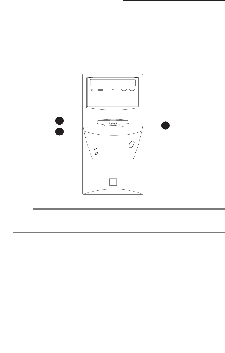
Front
NOTE
Some devices such as CD-ROM drive can be changed by user’s system
configuration.
1 Floppy Disk Drive
The floppy disk drive accepts 3.5-inch floppy diskettes.
2 Floppy Disk Drive Access Indicator
This indicator lights on while the drive is reading or writing data to a disk.
Wait until the light off before you remove a disk from the drive.
3 Eject Button
Press this button to eject any disk in the drive.
1
23
CHAPTER 1
1-4
Introduction
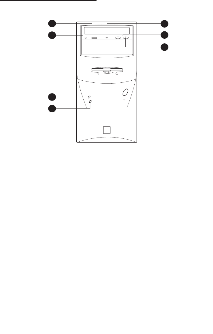
4 Disc Tray
The disc tray accepts a CD/DVD/CDRW/COMBO disk.
5 CD/DVD/CDRW/COMBO Drive
This drive is used to play DVD (DVD-ROM drive only), music CDs, photo CDs,
video CDs, or to load software package onto the hard disk drive.
6 Hard Disk Drive Access Indicator
This indicator lights on while the hard disk drive is reading or writing data to the
other disk.
7 Power Indicator
This Power indicator in the center of the power switch lights up when the
computer is on. This indicator lights on while your system is on.
8 Load/Eject Button
Pressing this button loads or ejects the CD/DVD/CDRW/COMBO tray.
9 Emergency Eject Hole
Insert a road in the hole to eject the tray only when your system is off.
10 Busy Indicator
This indicator lights on while initializing or data reading.
4
5
6
8
9
10
7
Introduction
1-5
CHAPTER 1
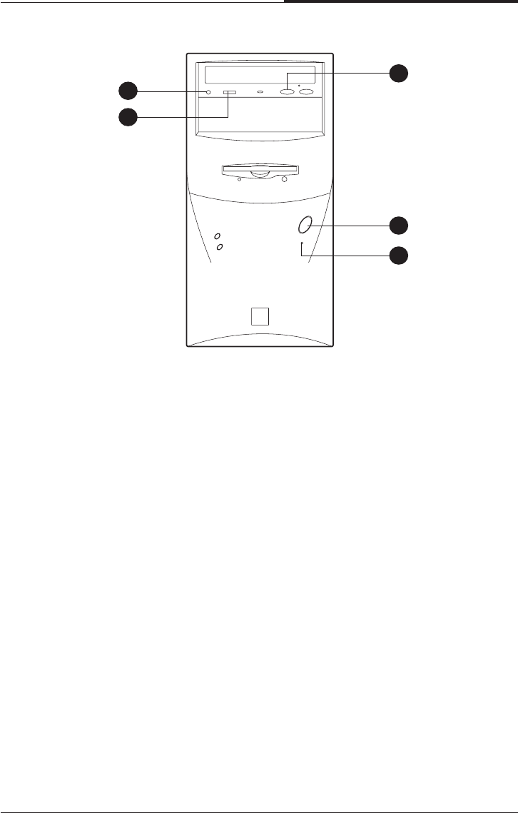
11 Play/Skip Button
Pressing this button plays an audio CD. The next song is played when the button
is pressed again.
12 HeadPhone JACK
Connect a headphone plug to this port when you want to hear an Audio CD with
headphone.
13 HeadPhone Volum Control
Adjust the headphone volume. (Only Audio CD)
14 Reset
15 Power Button
This button controls your system’s AC input power. When the system is off,
pressing the button makes your system on. The power indicator lights on while
the power of system is on. When your system is on, pressing the power button
turns off the system.
12
13
15
14
11
CHAPTER 1
1-6
Introduction
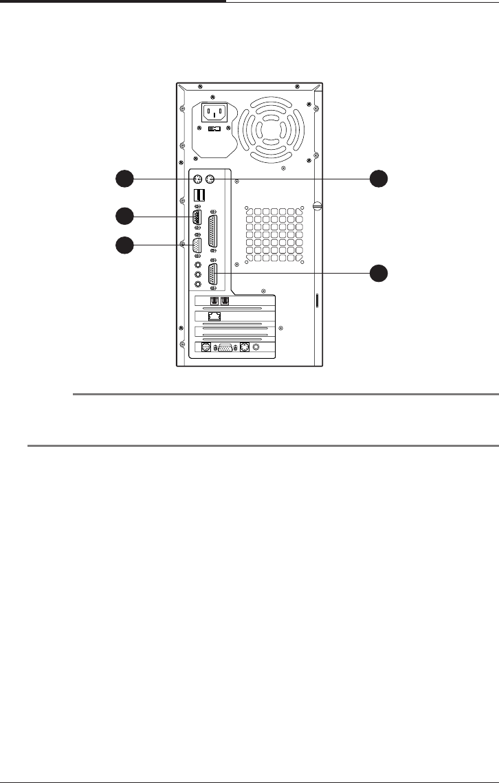
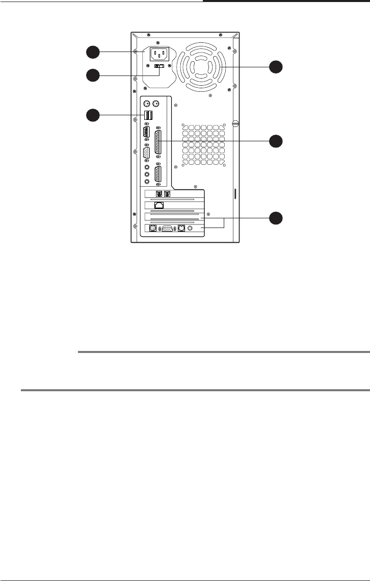
Rear
1 Keyboard Connector
This connector is for the PS/2 type’s Keyboard.
2 Serial Port (COM1) Connector
This connector is for serial devices such as an external modem, serial mouse,
and etc.
3 Video Connector
The signal cable from your monitor is connected with this connector.
4 Mouse Connector
This connector is for the PS/2 type’s mouse.
5 MIDI/Game Port Connector
Any MIDI or game input device such as a joystick, game pad, steering wheel,
and etc for playing computer game can be connected with this port.
NOTE
Your actual modem card may differ from the illustrations shown in this user’s
guide.
1
2
3
4
5
Introduction
1-7
CHAPTER 1
8 USB Connector
You can connect any USB compliant devices to the USB connector. USB
devices include low-speed peripherals such as microphone, digital joystick, and
speaker.
9 Option Card Slot Covers
10 Parallel Port (LPT1) Connector
This connector is for parallel devices such as a printer, and etc.
11 Air Ventilation Holes
The hole for air ventilation.
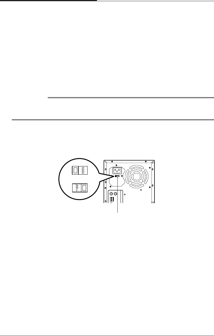
6 AC Power Receptacle
Your system power cable plugs into the AC power receptacle.
7 Voltage Selection Switch
The voltage selection switch must be set to match the AC power voltage you use.
CAUTION
Setting the voltage selection switch incorrectly will give the serious damage in your
system. Verify that the switch is set correctly before you power on your system.
6
7
8
11
10
9
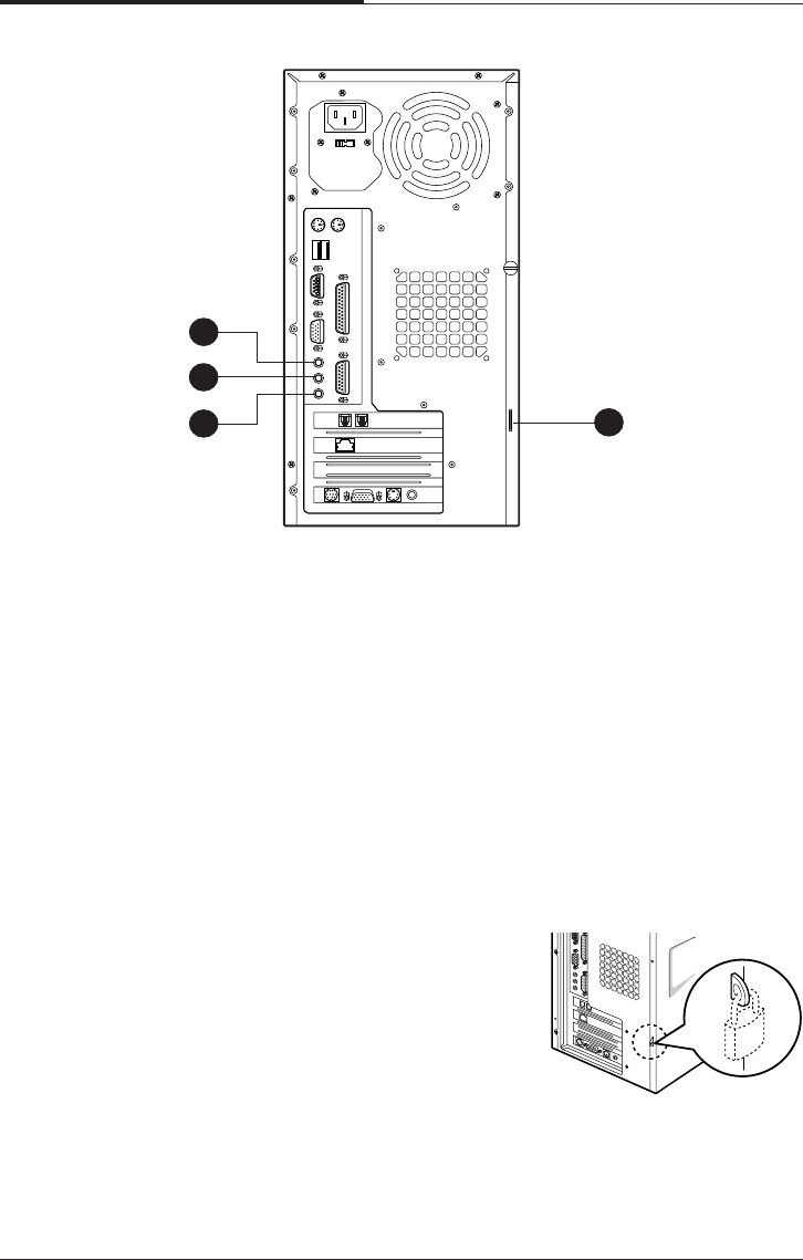
CHAPTER 1
1-8
Introduction
12 Speaker Jack
The Speaker jack can be used to attach most speakers with integrated amplifiers.
13 Line-in Jack
The jack is connected with the record/playback device such as a cassette player,
CD player, and etc. .
14 Microphone Jack
The jack is connected with the personal computer microphone to integrate your
voice or musical input into a sound application. .
15 Padlock Ring
The padlock ring allows you to secure the system
cover to the chassis to prevent unauthorized
access to the inside of the computer. To use
padlock ring, insert a commercially available
padlock through the ring and then lock the
padlock.
13
12
14 15
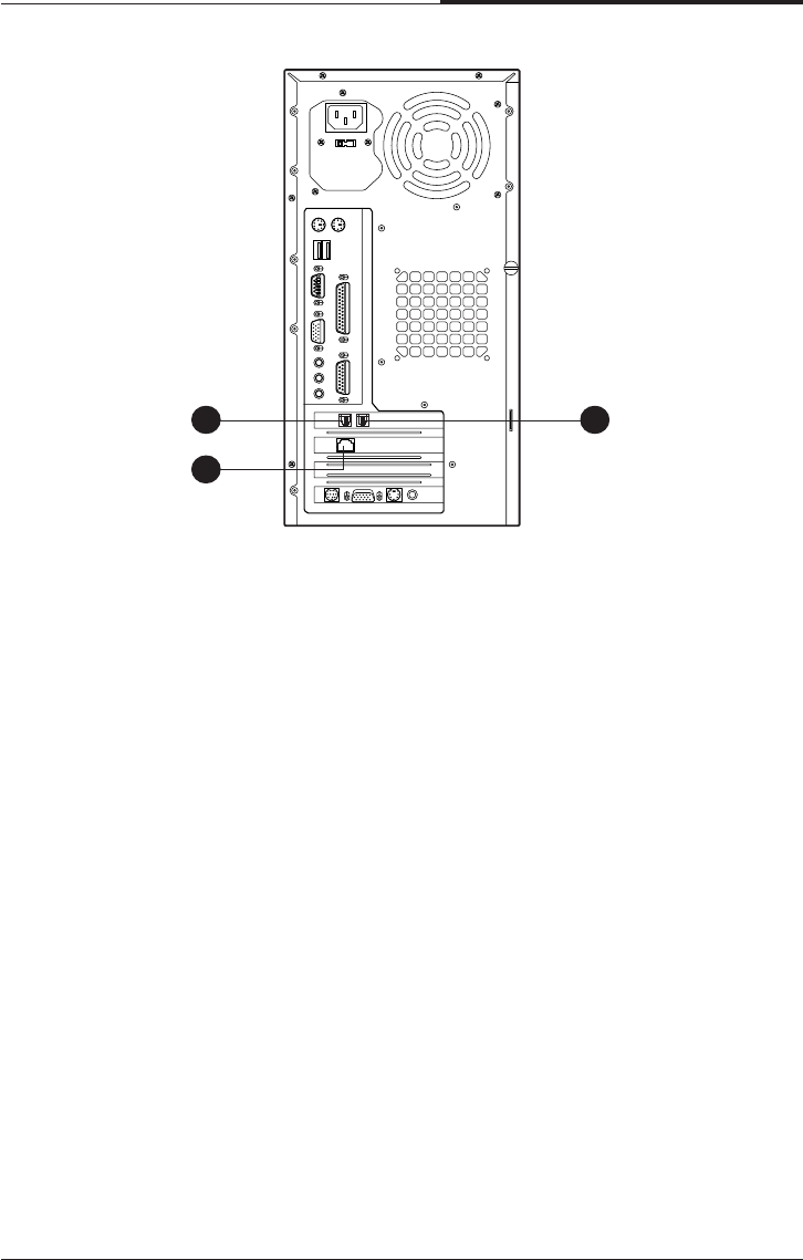
Introduction
1-9
CHAPTER 1
16 Phone Jack
You can connect the RJ11 phone jack cable from the telephone to this connector.
The jack is connected with the RJ11 phone jack cable from the telephone.
17 Wall Jack
You can connect the RJ11 wall jack cable for using faxes, e-mail, and internet
access. The jack is connected with the RJ11 wall jack cable to use faxes, e-mail,
internet access, and etc.
18 Ethernet Jack
16 17
18

CHAPTER 1
1-10
Introduction
Blank

Setting Up Your System
2-1
Setting Up Your System
Chapter 2Chapter 2
Chapter 2Chapter 2
Chapter 2
Setting Up Your System
This chapter describes how to set up and turn on/off your system. Just follow the
steps in this chapter.
1. Selecting a Location
Before you set up your computer, it is important to choose a safe and convenient
location that provides the following:
●A large, sturdy desk or table strong enough to support the weight of your system
and all of its components.
●A flat and hard surface. Soft surfaces like beds and carpeted floors attract static
electricity, which can erase data on your disks, damage the computer’s circuitry,
and prevent proper ventilation.
●Good air circulation. Leave several inches of space around the computer so air
can move freely.
●Moderate environment conditions. Select a cool, dry area and protect your
computer from extremes in temperature, humidity, dust, and smoke. Avoid direct
sunlight or any other source of heat.
●Appropriate power sources. To prevent static charges, connect all your equipment
to three-hole, grounded outlets. You need one outlet for the computer, one for the
monitor, and an additional outlet for a printer and any other peripheral devices.
●No electromagnetic interference. Do not place your system too close to any
electrical device, such as a telephone, which generates an electromagnetic field.
CHAPTER 2
2-2
Setting Up Your System
Using a tool such as an opened paper clip, slide the voltage selection switch to the
correct voltage position.
WARNING
If you set the voltage selection switch incorrectly, your system will have the serious
damage. Verify that the switch is set correctly before you power on your system.
2. Checking the Voltage Selection
A power supply is integrated into the system to provide power to the mainboard,
option cards, and peripheral devices. The power selection switch on the system back
panel can be used to set the power supply to operate at 115V or 220V.
To verify that your system has the correct setting for your environment, check the
voltage selection switch.
Voltage selection
switch
Setting Up Your System
2-3
CHAPTER 2
3. Connecting Your Peripheral Devices
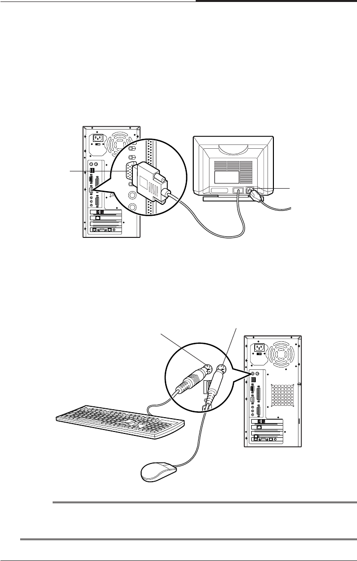
Connecting a Monitor
Connect the monitor cable to the video connector on the rear panel of your system.
If the connector has retaining screws, be sure to tighten them.
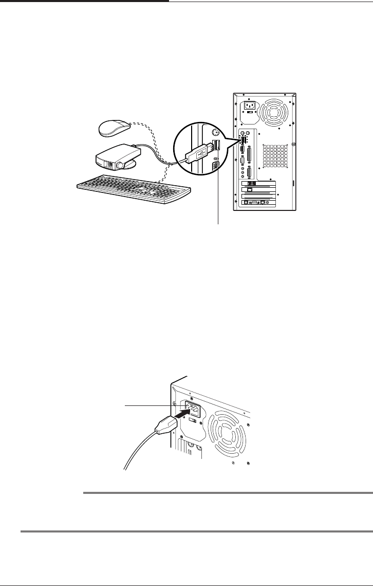
Connecting a Keyboard and Mouse
Plug the keyboard and mouse cable connectors into the keyboard and mouse
connectors on the rear panel of your system.
NOTE
Depending on the model, your keyboard may have no shortcut keys (Internet,
Email, Search, Mute, Volume Up, and Volume Down).
Video
connector Monitor power
receptacle
Keyboard
connector
Mouse connector
CHAPTER 2
2-4
Setting Up Your System
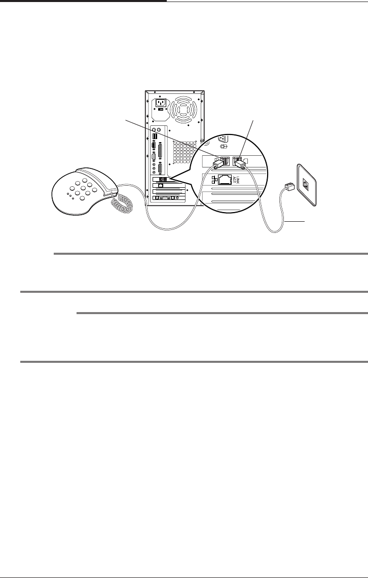
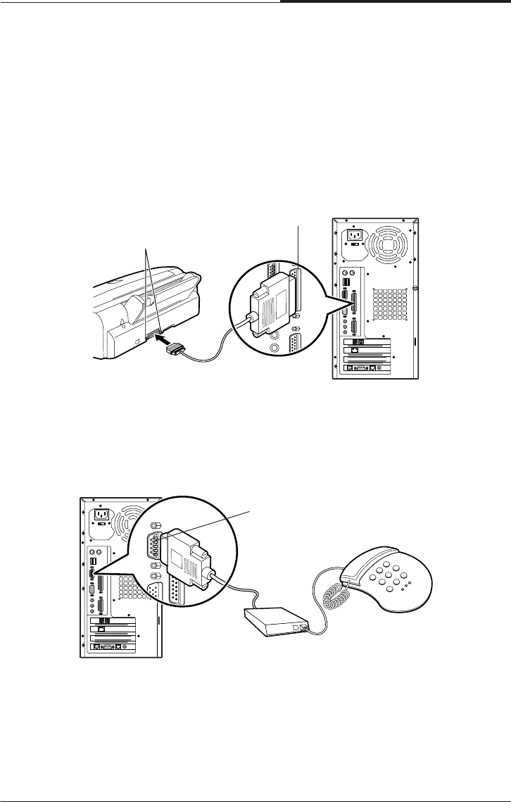
Connecting Modem Cables
if you use an optional modem card, connect the phone and wall lines to the modem
card.
NOTE
Depending on you computer model, your modem card can be different with the
picture. For more information about using the modem, refer the modem manual.
CAUTION
For protection of your computer during a lightning storm, unplug the wall jack
connector from the wall outlet. This will prevent damage to the computer due to
lightning.
Phone jack Wall jack
RJ11 cable
Setting Up Your System
2-5
CHAPTER 2
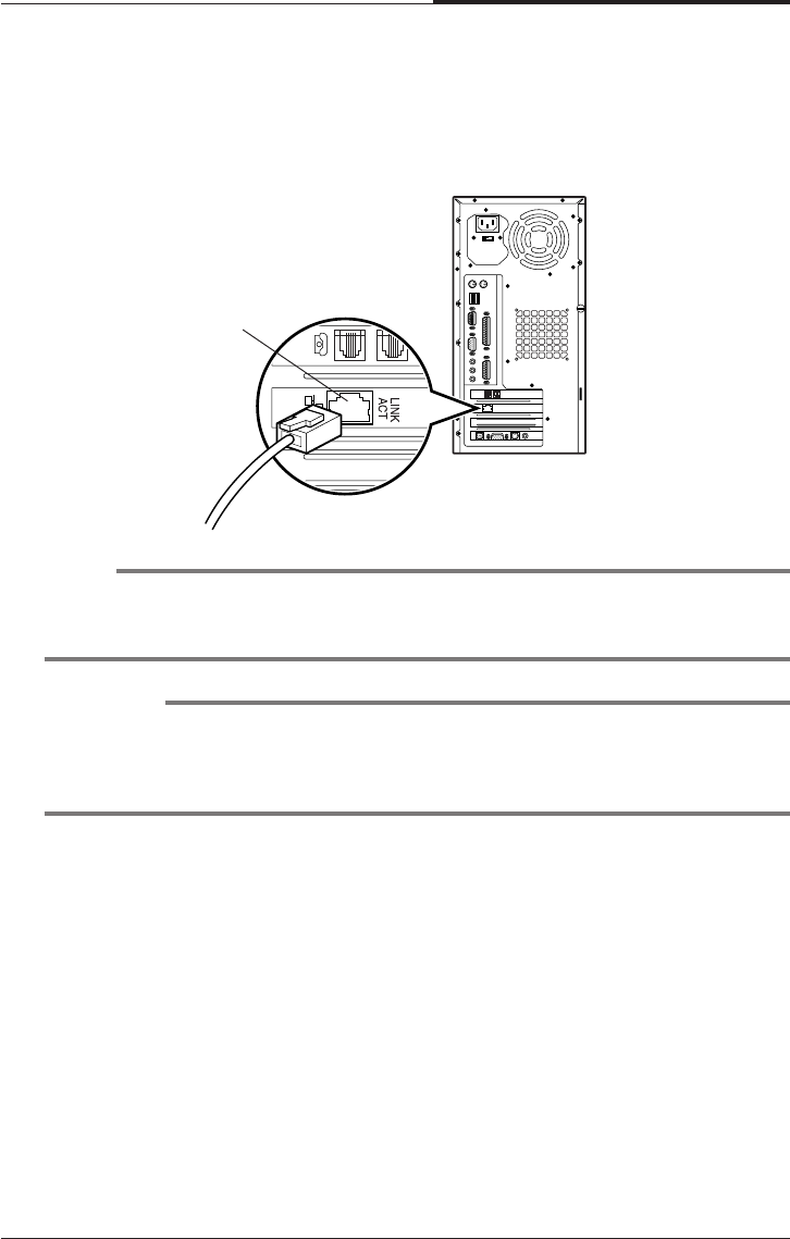
Connecting Ethernet Cables
If you use LAN card, Cabel modem card, ADSL card, and etc, connect the card with
Ethernet card as the below.
NOTE
If you use Windows ME, Ethernet card is already set up automatically.
If you use the other operating system, you must install Ethernet card driver.
CAUTION
To use high speed communication you must install the hardware driver and then
set up the protocol in Network property.
Refer the manual of high speed communication service provider.
RJ45 jack
CHAPTER 2
2-6
Setting Up Your System
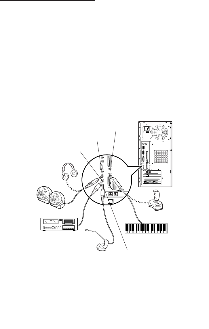
Connecting Audio Devices
Your computer has three integrated audio controller jacks (Speaker, Line-in, and
Microphone jack) and one MIDI/Game port connector.
You can connect a microphone to the microphone jack, a speaker or headphone to
the speaker jack, and a audio playback device such as cassette player, CD player, or
etc to the line-in jack.
Any MIDI or game input device such as a joystick, game pad, steering wheel, and
etc for playing computer game can be connected with this port.
Before you connect audio devices to the three jacks and the MIDI/Game port
connector, your system must be off. And then connect the devices with the each
connectors on the rear panel of your system.
Line-in jack
Speaker jack
MIDI/Game port connector
Headphone
Speakers
Cassette player
Microphone
MIDI keyboard
Joystick
Microphone jack
Setting Up Your System
2-7
CHAPTER 2
Connecting a Printer
Connect the printer cable connector with the parallel connector of your system. If
the plug has retaining screws, tighten them.
Connector the other side printer cable to the printer.
Connector the power line to the printer and plug it into an appropriate grounded
electrical outlet.
Connecting a Serial Device
If you have any serial device such as a printer, a modem, and etc, connect it to the
serial port of your system.
Clips
Parallel port
connector
Serial port
connector
CHAPTER 2
2-8
Setting Up Your System
Connecting a Power Cord
Before you plug the power cord into the wall socket, you should set the voltage
selection switch to correct position. The voltage selection switch must be set to
reflect the correct voltage the system operates on.
If you set the voltage selection switch to correct position, plug the power cord into
the AC power receptacle on the back panel. Then plug the other end of the power
cord into an appropriate grounded electrical outlet.
Connecting the USB Devices
If you use any USB devices, you can connect it to the USB connectors. Connect
USB device cable into the USB port of your system.
WARNING
To prevent an electronic shock, make sure to plug the cord into the system before you
plug it into the wall socket.
USB connector
AC power
receptacle

Setting Up Your System
2-9
CHAPTER 2
CAUTION
For protection of your computer and other devices during a lightning storm, or
when it is left unattended and unused for long periods of time, unplug the computer
and other devices from the wall outlet and disconnect the antenna or cable system.
This will prevent damage to the computer and other devices due to lighting and
power line surges.
4. Turning the Computer On and Off
Follow the instructions below to turn on the computer or to turn it off.
Turning On the Computer
To turn on your computer, follow the below steps.
1. Turn on the monitor and other devices connected to your system.
2. Press the power button on the front panel of your computer.
3. The system will load Windows ME.
Turning Off the Computer
To turn on your computer, follow the below steps.
1. Before you turn off computer, save all the data and then close all the application
programs you use.
2. Click the Start button, and then click Shut Down.
3. Select Shut down in the dialog box, and then click OK button.
4. Turn off the monitor and any other peripheral devices.

CHAPTER 2
2-10
Setting Up Your System
Blank
Using Your Computer
3-1
Using Your Computer
Chapter 3Chapter 3
Chapter 3Chapter 3
Chapter 3
Using Your Computer
To use your computer, you must install the operating system on your computer.
If you want to install Windows ME, follow the instructions in your Windows ME
manual. (Windows ME may be installed already on your system).
To install another operating system such as OS/2 Warp or UNIX, refer the manual
that came with the system).
The procedures in this manual assume that you are using Windows ME with your
computer.
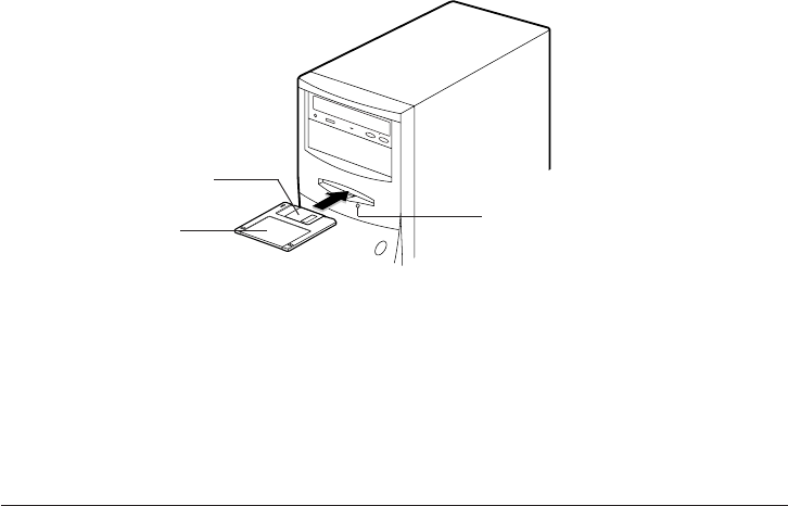
Using a Floppy Disk Drive
If you want to use 3.5 inch disk, insert the disk into 3.5 inch disk drive as the below
picture until it is placed on the proper position.
Eject button
Floppy disk
Metal shutter
CHAPTER 3
3-2
Using Your Computer
If you want to remove the disk, press the eject button after you make sure the drive
light is off.
NOTE
If you remove a disk or turn off the computer while the drive light is on, you can lose
data in the disk.
Also, remove all disks before you turn off the computer.
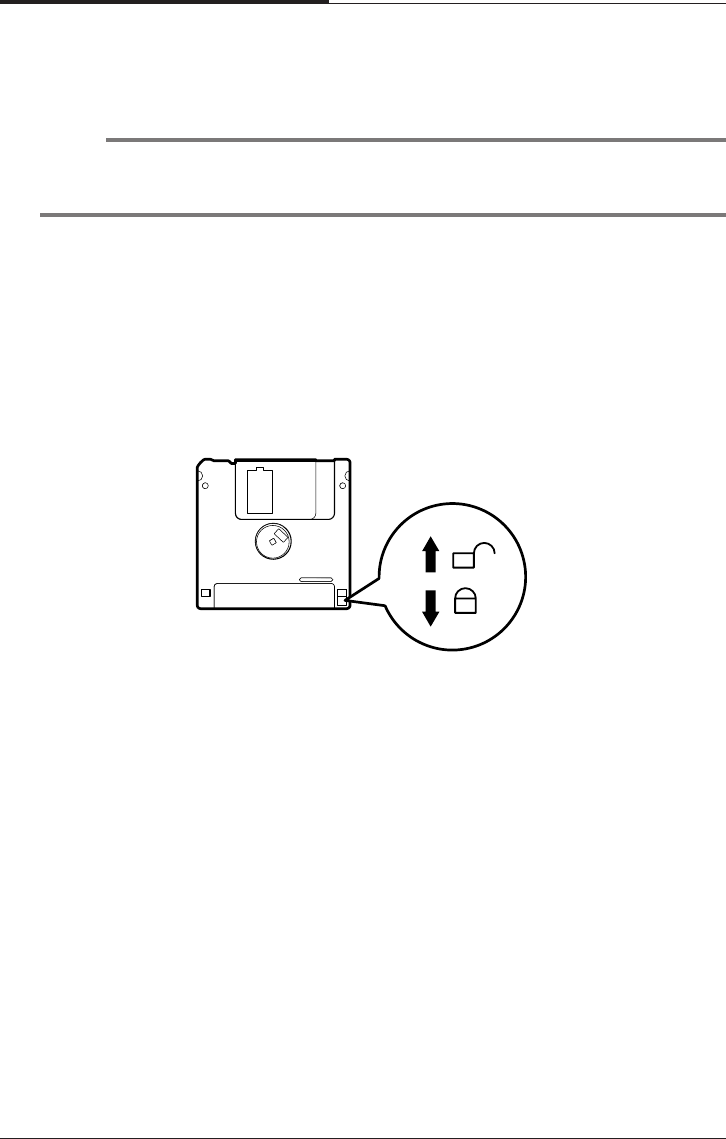
You can write-protect a disk to prevent its data from being altered. When a disk is
write-protected, you can read it and copy data from it, but you cannot store new data
on it or delete any files it contains.
The write-protect is on the back of a 3.5 inch disk as the below picture. If you want
to use write-protect, slide the switch toward the edge of the disk.
Using Your Computer
3-3
CHAPTER 3
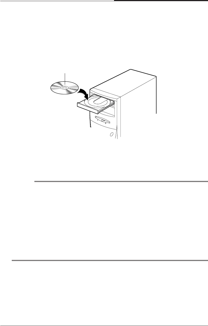
Using a CD/DVD-ROM Drive
To use CD/DVD ROM drive, turn on your system and then press the load/eject
button. When the disk tray pops out, put CD/DVD title in the tray with the label side
up. Press the load/eject button again or gently push the disk tray to close it. During
the procedure, the busy indicator will flash.
If you want to remove the CD/DVD title, make you sure that the busy indicator is
off. Press load/eject button, and then remove CD/DVD title when the disk tray pops
out. Press load/eject button again to close the tray.
NOTES
When your system is turned off, you may need to open the CD/DVD tray. At this
time, insert a fine rod such as an opened paper clip into the emergency eject hole as
far as it will go. When the tray is slightly open, carefully pull it out.
Your computer references the CD/DVD-ROM drive as D: unless you have more
than one hard disk drive or partition. Then it automatically recognizes it as the
next available drive letter.
The high speed DVD-ROM drive (above 6x) may take few seconds to stop the
running of the spindle motor when you press the eject button, immediately after
using CD or DVD title, to open the tray. Wait about 5 to 10 seconds after pressing
the eject button to give the DVD drive sufficient time to stop the running of the
spindle motor and eject the tray.
CD/DVD-ROM disc
CHAPTER 3
3-4
Using Your Computer
If you want to remove the CD/CDRW/DVD title, make you sure that the busy
indicator is off. Press load/eject button, and then remove CD/CDRW/DVD title
when the disk tray pops out. Press load/eject button again to close the tray.
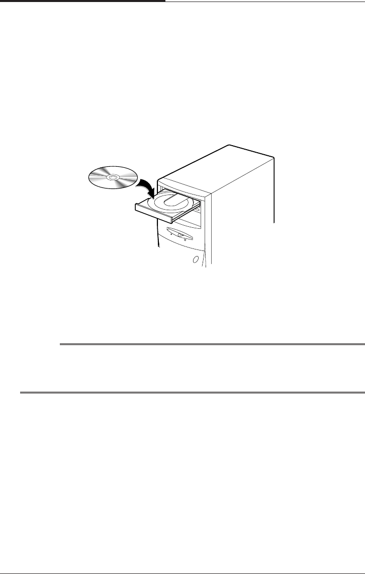
Using a CDRW/COMBO Drive
To use CD/CDRW/DVD ROM drive, turn on your system and then press the load/
eject button. (CDRW drive does not recognize DVD title.)
When the disk tray pops out, put CD/CDRW/DVD title in the tray with the label side
up. Press the load/eject button again or gently push the disk tray to close it. During
the procedure, the busy indicator will flash.
NOTES
When your system is turned off, you may need to open the CDRW/COMBO tray.
At this time, insert a fine rod such as an opened paper clip into the emergency eject
hole as far as it will go. When the tray is slightly open, carefully pull it out.
Using Your Computer
3-5
CHAPTER 3
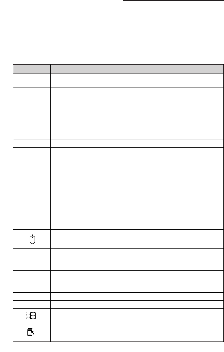
Using Special Keys on the Keyboard
Keys on the keyboard, that are described in the following table serve special
functions when your computer is running your operating system or application
programs.
Purpose
Num Lock
Ta b
Caps Lock
Key
Shift
Ctrl
Alt
Backspace
( )
Enter
Insert
Delete
Esc
F1-F12
Print Screen
Sys Rq
Moves the cursor one tab to the right in normal mode and one tab to the
left in Shift mode.
Changes the letter keys from lowercase to uppercase; changes back to
lowercase when pressed again. The numeric/symbol keys on the top row of
the keyboard and the symbol keys in the main part of the keyboard are not
affected.
Produces uppercase characters or the top symbols on the keys when used
with the main character keys. Produces lowercase characters when the
Caps Lock function is on.
Works with other keys to perform special (control) function.
Works with other keys to enter alternate character codes or functions.
Moves the cursor back one space, deleting the character to the left of the
cursor.
Ends a line of keyboard input or executes a command.
Turns the insert function on and off.
Deletes the character marked by the cursor.
Control cursor location.
Controls the current command line or operation.
Changes the function of the numeric/cursor keys from entering numbers to
positioning the cursor.
Changes use of the numeric keys on the numeric keypad as mouse keys. To
enable the function of the key, set the Mouse tab in "Accessibility Options" in
Control panel.
Perform special functions within application programs.
Outputs the screen display captured on the clipboard. When used with alt
key, this key captures active window.
Captures the screen display on the clipboard. When used with Alt key, this
key captures active window.
Controls scrolling in some applications.
Suspends the current operation.
Stops the current operation (used with Ctrl).
Displays the start menu.
Displays the short menu for the selected location. It corresponds to the right
button of a mouse and displays a different menu applicable to Windows 98
other application programs.
↓
↓
↓
↓
, , ,
Home, End,
PgUp, PgDn,
Scroll Lock
Pause
↓
Break

CHAPTER 3
3-6
Using Your Computer
Key Purpose
Internet* Launches the Internet browser.
Email* Launches an e-mail application.
Search* Launches an Internet search page.
Mute* Mutes the sound.
Volume Up* Increases the current volume level.
Volume Down* Lowers the current volume level.
*Depending on the model, your keyboard may have no these keys.
The Caps Lock, Num Lock, and Scroll Lock keys work as toggles; press the key
once to turn on a function and again to turn it off. When the function is enabled, the
corresponding light in the upper right corner of the keyboard is on.
The numeric keys on the numeric keypad of your keyboard can be used as
MouseKeys to move a mouse pointer. To use the numeric keys as MouseKeys, first
you should set the Mouse tab in “Accessibility Options” of the Control Panel.
NOTES
Depending on the model, your keyboard may have no shortcut keys (Internet,
Email, Search, Mute, Volume Up, and Volume Down).
In case of Easy Keyboard, you can configure the Internet, Email, and Search
buttons to launch an application or Internet browser of your choice. To do this, click
Start, point to Easy Keyboard, and then click Key Configuration. When the
Shortcut Key Configuration window appears, select the execution files for the
buttons.

Using Your Computer
3-7
CHAPTER 3
Using a Mouse
Generally a mouse functions as follows:
●Click ( ) : Press and release the left mouse button once.
●Double click ( ) : Quickly press and release the left mouse button twice.
●Click with the right mouse button ( ) : Press and release the right mouse
button once.
●Drag ( ) : While pressing and holding down the left or right mouse
button, move it to another location and then release the mouse button.
When using Windows ME, you can change mouse button configurations in the
Mouse section of the Control Panel. If you are left-handed, you can change
configuration from right-handed to left-handed.
See “mouse, reversing buttons” in the Help index for more information.
CHAPTER 3
3-8
Using Your Computer
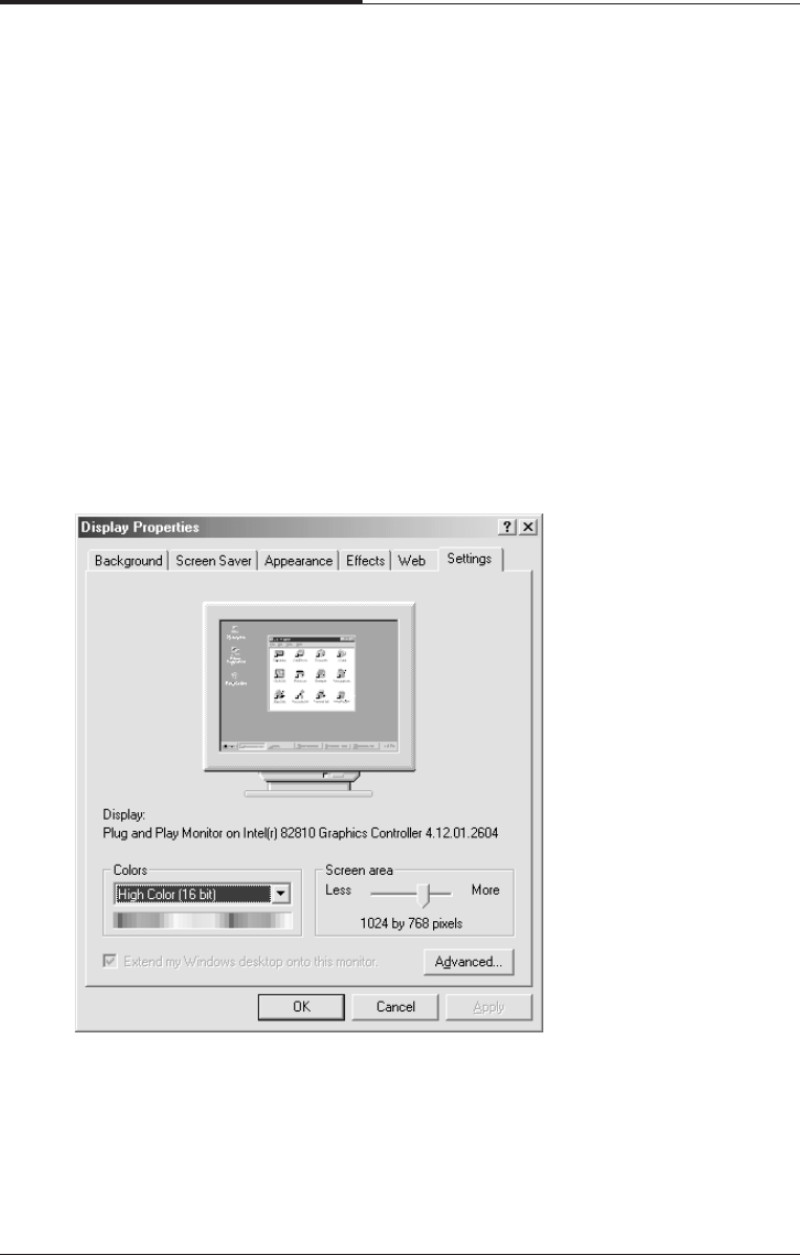
Changing the Display Resolution and
Color Depth
To change the display resolution and color depth, follow the below steps.
1. Point to Settings after click the Start button, and then click Control Panel.
2. Double click the Display icon, or click the right mouse button on the empty
desktop area and then click Properties.
3. When the Display Properties window appears, click the Settings tab.
4. Select the color depth from the Colors area and the resolution from the Screen
area.
5. Click the OK button.
Using Your Computer
3-9
CHAPTER 3
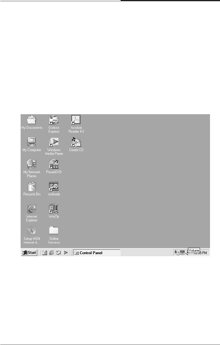
Controlling the Audio Volume
You can control the audio volume level by using the volume up/down button on the
keyboard,
volume control box, or Master window.
To control the audio volume by using the volume control button, press the volume
up/down button on the keyboard.
To control the audio volume in the control box, follow the below steps.
1. Click on the Speaker icon located on the right of your Windows taskbar.
CHAPTER 3
3-10
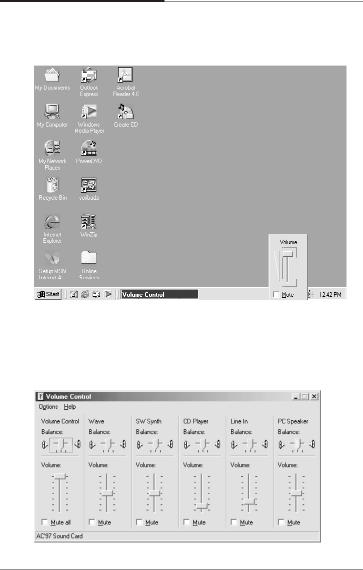
Using Your Computer
To control the audio volume level for each device by using the Master Out window,
follow the below steps:
1. Double click the Speaker icon located on the Windows Me taskbar.
2. Adjust audio volume level by using the volume bar up or down when the volume
control box appears.
Using Your Computer
3-11
CHAPTER 3
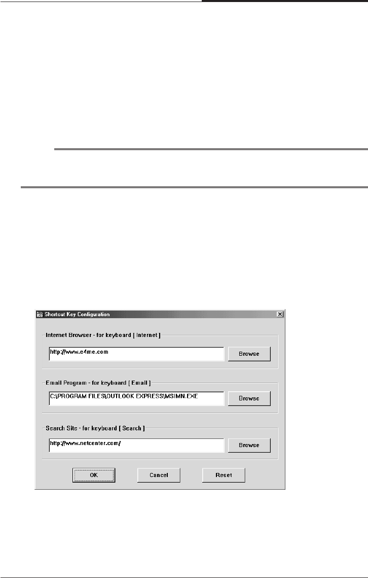
Your system provides a configuration program for mapping programs to the Shortcut
keys (Internet, Email, and Search) on the upper-right corner of the keyboard.
To map a certain program for short-cut key on the keyboard, follow the below seeps
1. Point to Programs after click Start, and then click Key Configuration.
2. The Shortcut Key Configuration window will appear.
2. Adjust audio volume level by using the volume bar up or down when the Master
Out window appears.
3. Click the Close button.
Configuring Shortcut Keys
NOTE
The configuration program is available only on the Easy Keyboard (has shortcut
keys) model.

CHAPTER 3
3-12
Using Your Computer
3. Click the Browse button.
4. Select a program file for the shortcut key when the Open window appears.
5. Click the Open button.
6. In the Shortcut Key Configuration window, click OK.
Click OK in the Shortcut Key Configuration window.

BIOS Configuration
4-1
BIOS Configuration
Chapter 4Chapter 4
Chapter 4Chapter 4
Chapter 4
BIOS Configuration
Award’s BIOS ROM has a built -in Setup Program that allows users to modify the
basic system configuration. This type of information is stored in battery-backed
CMOS RAM so that it retains the Setup information when the power is turned off
4.1 Entering Setup
Power On the Computer, and then pressing <Del> key immediately will allow you
to enter Setup.
If the message disappears before you respond and you still wish to enter Setup,
restart the system to try again by turning it OFF then ON or pressing the "RESET"
bottom on the system case. You may also restart by simultaneously press <Ctrl>,
<Alt>, and <Del> keys.

CHAPTER 4
4-2
BIOS Configuration
4.2 Control Keys
Up arrow Move to previous item.
Down arrow Move to next item.
Left arrow Move to the item in the left hand.
Right arrow Move to the item in the Right hand.
Esc Key Main Menu - Quit and not save changes into CMOS
Status Page Setup Menu and Option Page Setup Menu-Exit
Current page and return to Main Menu.
PgUp Key Increase the numeric value or make changes.
PgDn Key Decrease the numeric value or make changes.
F1 Key General help, only for Status Page Setup Menu and Option Page Setup Menu
F2 Key Reserved
F3 Key Reserved
F4 Key Reserved
F5 Key Restore the previous CMOS values from CMOS, only for Option Page Setup
Menu
F6 Key Load the default CMOS value from Fail-Safe default table, Only for Option
Page Setup Menu
F7 Key Load Optimized defaults
F8 Key Reserved
F9 Key Reserved
F10 Key Save all the CMOS changes and exit
4.3 Getting help
4.3.1 Main Menu
The on-line description of the highlighted setup function is displayed at the bottom
of the screen
4.3.2 Status Page Setup Menu/Option Page Setup
Menu
Press F1 Key to pop up a small help window that describes the appropriate keys to
use and the possible selections for the highlighted item. To exit the Help Window
press <ESC> Key.
BIOS Configuration
4-3
CHAPTER 4
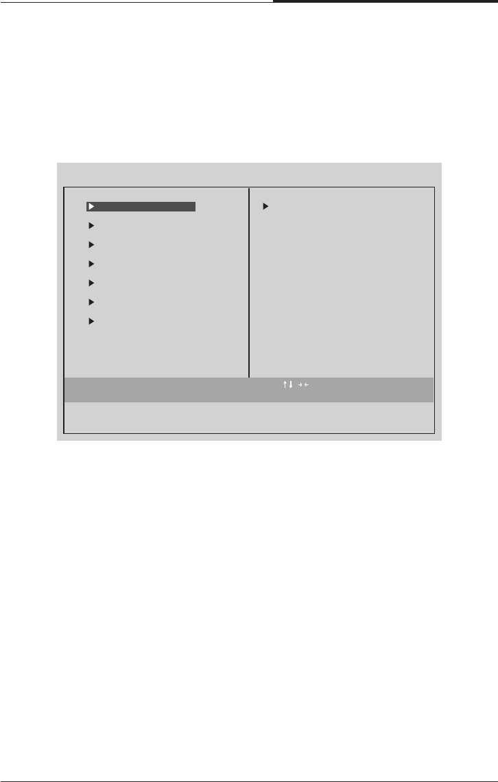
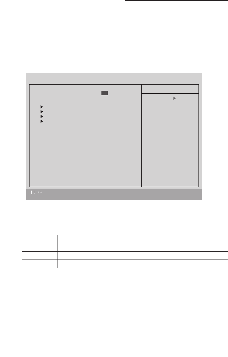
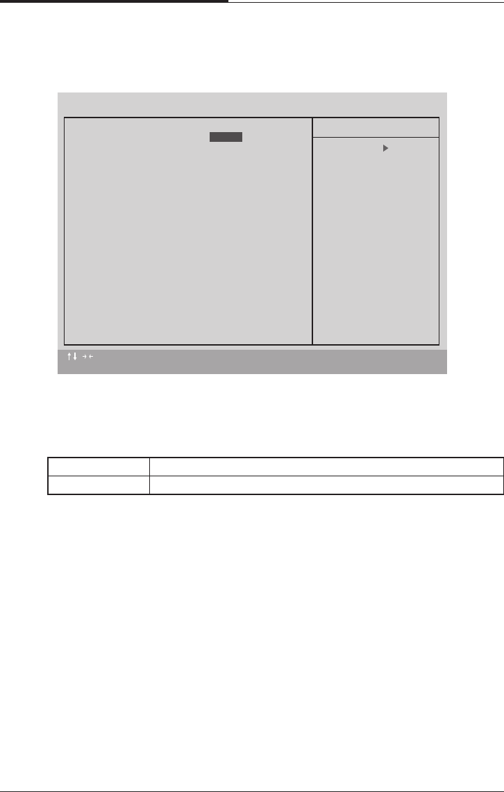
4.4 The Main Menu
Once you enter Award BIOS CMOS Setup Utility, the Main Menu(Figure 4.1) will
appear on the screen. The Main Menu allows you to select from nine setup functions
and two exit choice. Use arrow keys to select among the items and press <Enter>
Key to accept or the sub-menu.
●Standard CMOS Features
This setup page includes all the items in standard compatible BIOS.
●Advanced BIOS Features
This setup page includes all the items of Award special enhanced features.
●Advanced Chipset Features
This setup page includes all the items of chipset special features.
●Integrated Peripherals
This setup page includes all onboard peripherals
●Power Management Setup
This setup page includes all the items of Green function features.
Esc : Quit : Select Item
F10 : Save & Exit Setup
CMOS Setup Utility - Copyright (C) 1984-1999 Award Software
Advanced BIOS Features
Advanced Chipset Features
Integrated Peripherals
Power Management Setup
PnP/PCI Configurations
PC Health Status
Time, Date, Hard Disk Type...
Frequency/Voltage Control
Load Fail-Safe Defaults
Load Optimized Defaults
Set Supervisor Password
Set User Password
Save & Exit Setup
Exit Without Saving
Standard CMOS Features

CHAPTER 4
4-4
BIOS Configuration
●PnP/PCI Configuration
This setup page includes all the configurations of PCI & PnP ISA resources.
●PC Health Status
This setup page includes the system auto detect temperature, voltage, fan, speed.
●Frequency/Voltage Control
This setup page includes control CPU’s clock and frequency ratio.
●Load Fail Safe Defaults
Fail-Safe Defaults indicates the value of the system parameters which the system
would be in safe configuration.
●Load Optimized Defaults
Optimized Defaults indicates the value of the system parameters which the
system would be in best performance configuration.
●Set Supervisor password
Change, set, or disable password. It allows out limit access to the system and
Setup, or just to Setup.
●Set User password
Change set, or disable password. It allows you to limit access to the system.
●Save & Exit Setup
Save CMOS value setting to CMOS and exit setup.
●Exit Without Saving
Abandon CMOS Vale changes and exit setup.
BIOS Configuration
4-5
CHAPTER 4
4.5 Standard CMOS Features Menu
The items in Standard CMOS Setup Menu (Figure 4.2) are divided into 9 categories.
Each category includes no, one or more than one setup items.
Use the arrows to highlight the item and then use the <PgUp> or <PgDn> keys to
select the value you want on each item.
●Date
The date formats is <week>, <month> <day> <year>
Week The week, from Sun to Sat, determined by the BIOS and is Display-only
month The month, Jan. Though Dec
day The day, from 1 to 31 (or the maximum allowed in the month
year The year, from 1994 through 2079
●Time
The times format in <hour> <minute> <second>. The time is calculates base on
the 24-hour military-time clock. For example, 1 p.m. is 13:00:00.
:Move Enter : Select +/-/PU/PB : Value F10 : SAVE ESC : Exit F1 : General Help
F5 : Previous Values F6 : Fail-Safe Defaults F7 : Optimized Defaults
CMOS Setup Utility - Copyright (C) 1984-1999 Award Software
Standard CMOS Features
Date (mm: dd: yy) Fri, 19 2001
Time (hh: mm: ss) 20 : 36 : 48
IDE Primary Master Press Enter 10205 MB
IDE Primary Slave Press Enter None
IDE Secondary Master Press Enter None
IDE Secondary Slave Press Enter None
Drive A 1.44M, 3.5 in.
Drive B None
Floppy 3 Mode Support Disabled
Video EGA/VGA
Halt On All, But Keyboard
Base Memory 640K
Extended Memory 63438K
Total Memory 64512K
Item Help
Menu Level
Change the day. month,
year and century
Jan
CHAPTER 4
4-6
BIOS Configuration
●IDE Primary Master, Slave / Secondary Master, Slave
The category identifies the types of hand disk form drive C to F that has been
installed in the computer.
There are three types: auto type, manual definable type and none type user type is
user-definable; Auto type which will automatically detect HDD type.
Note that the specifications of your drive must be matched with the driver table.
The hard disk will not work properly if you enter improper information for this
category.
If you select Manual type, related information will be asked to enter to the
following items.
Enter the information directly from the keyboard and press<ENTER> key.
Such information should be provided in the documentation form our hard disk
vendor or the system manufacturer.
# a hard disk has not been installed select NONE and press <Enter> Key
●Drive A type / Drive B type
The category identifies the types of floppy disk driver A or driver B that has been
installed in the Computer
Name No floppy driver installed
360K, 5.25 in 5.25 inch PC-type standard driver; 360K byte capacity
1.22M, 5.25 in 5.25 inch AT-type high-density drive; 1.2M byte
capacity (3.5 inch when 3 Mode is Enable)
720K, 3.5 in 3.5 inch double-side drive; 720K byte capacity
1.44M, 3.5 in 3.5 inch double-side drive; 1.44M byte capacity
2.88M, 3.5 inch 3.5 inch double-side drive; 2.88M byte capacity
CYLS Number of cylinders
HEADR number of heads
PRECOMP write precomp
LANDZONE Landing Zone
SECTORS number of sectors
Disabled Normal Floppy Drive
Drive A Drive A is 3 mode Floppy Drive
Drive B Drive B is 3 mode Floppy Drive
Both Drive A & B are mode Floppy Drive
●Floppy 3 Mode Support (for Japan Area)

BIOS Configuration
4-7
CHAPTER 4
●Video
The Category detects the type of adapter used for the primary system monitor
that match your video display card and monitor. Although secondary monitors
are supported, you do not have to select the type in setup.
EGA\VGA Enhanced Graphics Adapter/Video Graphics Array.
For EGA, VGA, SVGA, or PGA monitor adapters
CGA 40 Color Graphics Adapter, power up in 40 column mode
CGA 80 Color Graphics Adapter, power up in 80 column mode
MONO Monochrome adapter, includes high resolution monochrome
adapters
●Halt on
The category determines whether the computer will stop if an error is detected
during power up.
NO Errors The system boot will not stop for any error that may be Detected and
you will be prompted
All Errors Whenever the BIOS detects a non-fatal error the system will be
stopped
All, But The system boot will not stop for a keyboard error,
Keyboard stop for all other errors
(Default)
All, But The system boot will not stop for a disk error;
Disk it will stop for all other errors
All, But The system boot will not stop for a keyboard or disk error;
Disk/key it will stop for other error
●Memory
The category is display-only which is determined by POST (Power On Self Test)
of the BIOS.
Base Memory
The POST of the BIOS will determine the amount of base(or conventional)
memory installed in the system.
The value of the base memory is typically 512K for systems with 512K memory
installed in the motherboard, or 640K for systems with 640K or more memory
installed on the motherboard.
Extended Memory
The BIOS determines how much extended memory is present during the POST.
This is the amount of memory located above 1MB in the CPU’s memory address
map.
CHAPTER 4
4-8
BIOS Configuration
●Virus Warning
If it is set to enable, the category will flash on the screen when there is any
attempt to write to the boot Sector or partition table of the hard disk driver.
The system will halt and the following error message will appear in the mean
time.
You can run anti-virus program to locate the problem.
4.6 Advanced BIOS Features
Enable Activate automatically when the system boots up causing a Warning
message to appear when anything attempts to Access the boot sector
or hard disk partition table
Disable No warning message to appear when anything attempts to Access the
boot sector or hard disk partition table
:Move Enter : Select +/-/PU/PB : Value F10 : SAVE ESC : Exit F1 : General Help
F5 : Previous Values F6 : Fail-Safe Defaults F7 : Optimized Defaults
CMOS Setup Utility - Copyright (C) 1984-1999 Award Software
Advanced BIOS Features
Virus Warning
First Boot Device CDROM
Second Boot Device Floppy
Third Boot Device HDD-0
Boot Up Floppy Seek Enabled
Boot Up NumLock Status On
Typematic Rate Setting Disabled
Typematic Rate [Chars/Sec] 6
Typematic Delay [Msec] 250
Security Option Setup
HDD S.M.A.R.T. Capabillity Disabled
Report No FDD For WIN 95 No
Item Help
Menu Level
Allows you to choose
the VIRUS warning
feature for IDE Hard
Disk boot sector
protection. If this
function is emabled
and someone attempt to
write date into this
area, BIOS will show a
warning message on
screen and alarm beep
Disabled

BIOS Configuration
4-9
CHAPTER 4
●Boot Up Floppy Seek
During POST, BIOS will determine the floppy disk drive installed is 40 or 80
Tracks. 360K type is 40 tracks 720K, 1.2M and 1.44M are all 80 tracks.
The default value is Enable.
Floppy Select your boot device priority by Floppy
LS120 Select your boot device priority by LS120
HDD-0~3 Select your boot device priority by HDD-0~3
SCSI Select your boot device priority by SCSI
CDROM Select your boot device priority by CDROM
ZIP100 Select your boot device priority by ZIP100
DISABLE Disable this function
LAN Select your boot device priority by LAN
●First / Second / Third Boot device
The default value is floppy / HDD-0 / LS120
Enable BIOS searches for floppy disk drive to determine it is 40 or 80 tracks.
Note that BIOS can not tell from 720K, 1.2M or 1.44M drive type as
they are all 80 tracks
DISABLE BIOS will not search for the type of floppy disk drive by track Number.
Note that there will not be any warning message if The drive installed
is 360K
●Boot Up NumLock Status
The default value is On
ON Keypad is number keys
Off Keypad is arrow keys
●Typematic Rate Setting
The default value is Disabled
Enabled Enable Keyboard Typematic rate setting.
Disable Disable Keyboard Typematic rate setting.

CHAPTER 4
4-10
BIOS Configuration
●Typematic Delay (Msec)
The default value is 250
System The can not boot and can not access to Setup page
Will be denied if the current password is not entered at
The prompt
Setup The system will boot, but access to setup will be denied if the correct
password is not entered at the prompt
6-30 Set the maximum Typematic rate from 6 chars. Per second to 30
characters. Per second
●Typematic Rate (Chars / Sec)
The default value is 6
250-1000 Set the time delay from first key to repeat the same key in to
computer
●Security Option
This category allows you to limit access to the system and Setup, or just to Setup.
The default value is setup.
●HDD S.M.A.R.T. Capability
The default value is Disable
Enable Enable HDD S.M.A.R.T. Capability
Disable Disable HDD S.M.A.R.T. Capability
●Report No FDD For WIN95
The default value us No.
No Assign IRQ6 For FDD
Yes FDD Detect IRQ6 Automatically
BIOS Configuration
4-11
CHAPTER 4
4.7 Advanced Chipset Features
●Top Peformance
The default value is Disabled
Disable Set Top Performance Disable.
Enable Set Top Performance Enable.
●SDRAM CAS latency Time
3 For 67/83 MHz SDRAM DIMM module|
2 For 100 MHz SDRAM DIMM module.
Auto Set SDRAM CAS latency Time to Auto
●SDRAM Cycle Time Tras/Trc
The default value is 5/7
6/8 Set DRAM Tras/Trc Cycle time is 6/8 SCLKs
5/7 Set DRAM Tras/Trc Cycle time is 5/7 SCLKs
:Move Enter : Select +/-/PU/PB : Value F10 : SAVE ESC : Exit F1 : General Help
F5 : Previous Values F6 : Fail-Safe Defaults F7 : Optimized Defaults
CMOS Setup Utility - Copyright (C) 1984-1999 Award Software
Advenced Chipset Features
Top Performance
SDRAM CAS Latency Time Auto
SDRAM Cycle Time Tras/Trc 5/7
SDRAM RAS-to-CAS Delay 2
SDRAM RAS Precharge Time 2
SDRAM Buffer Strength Auto
Delayed Transaction Disabled
Local Memory Frequency 100 Mhz
Item Help
Menu Level
Disabled

CHAPTER 4
4-12
BIOS Configuration
●Delayed Transaction
The default value is Disabled
●Local Memory Frequency
The default value is 100MHz
3 Set SDRAM RAS-to-CAS delay 3 SCLKs
2 Set SDRAM RAS-to-CAS delay 2 SCLKs
Auto Set SDRAM Buffer Strengh Auto
Auto-1 Set SDRAM Buffer Strengh Auto-1
Auto+1 Set SDRAM Buffer Strengh Auto+1
●SDRAM RAS-to CAS delay
The default value is 2
3 Set SDRAM RAS Precharge is 3
2 Set SDRAM RAS Precharge is 2
●SDRAM RAS Precharge
The default value is 2
●SDRAM Buffer Strengh
The default value is Auto
Disabled Normal operation.
Enable For slow speed ISA device in system
100MHz Set Local Memory Frequency to 100MHz
133MHz Set Local Memory Frequency to 133MHz
BIOS Configuration
4-13
CHAPTER 4
●On-Chip Primary PCI IDE
The default value is Enabled.
●On-Chip Secondary PCI IDE
The default value is Enabled.
●IDE Primary Master PIO (for Onboard IDE 1st channel)
The default value is Auto
4.8 Integrated Peripherals
Enabled Enable onboard 1st channel IDE port
Disabled Disable onboard 1st channel IDE port.
Enabled Enable onboard 2nd channel IDE port
Disable Disable onboard 2nd channel IDE port
Auto BIOS will automatically detect the IDE HDD Accessing mode
Mode0~4 Manually set the DE Accessing mode.
:Move Enter : Select +/-/PU/PB : Value F10 : SAVE ESC : Exit F1 : General Help
F5 : Previous Values F6 : Fail-Safe Defaults F7 : Optimized Defaults
CMOS Setup Utility - Copyright (C) 1984-1999 Award Software
Integrated Peripherals
On-Chip Primary PCI IDE
On-Chip Secondary PCI IDE Enabled
IDE Primary Master P10 Auto
IDE Primary Slave P10 Auto
IDE Secondary Master P10 Auto
IDE Secondary Slave P10 Auto
IDE Primary Master UDMA Auto
IDE Primary Slave UDMA Auto
IDE Secondary Master UDMA Auto
IDE Secondary Slave UDMA Auto
USB Controller Enabled
USB Keyboard Support Disabled
Init Dispaly First PCI Slot
AC97 Audio Auto
AC97 Modem Auto
IDE HDD Block Mode Enabled
POWER ON Function BUTTON ONLY
KB Power ON Password Enter
Onboard FDC Controller Enabled
Item Help
Menu Level
Enabled

CHAPTER 4
4-14
BIOS Configuration
●IDE Primary Slave PIO (for Onboard IDE 1st channel)
The default value is Auto
●IDE Secondary Master PIO (for Onboard IDE 2nd channel)
The default value is Auto
●IDE Secondary Slave PIO (for Onboard IDE 2nd channel)
The default value is Auto
●IDE Primary Master UDMA
The default value is Auto
●IDE Primary Slaver UDMA
The default value is Auto
●IDE Secondary Master UDMA
The default value is Auto
●IDE Secondary Slaver UDMA
The default value is Auto
Auto BIOS will automatically detect the IDE HDD Accessing mode
Mode0~4 Manually set the DE Accessing mode.
Auto BIOS will automatically detect the IDE HDD Accessing mode
Mode0~4 Manually set the DE Accessing mode.
Auto BIOS will automatically detect the IDE HDD Accessing mode
Mode0~4 Manually set the DE Accessing mode.
Auto BIOS will automatically detect the IDE HDD Accessing mode
Disable Disable UDMA function.
Auto BIOS will automatically detect the IDE HDD Accessing mode
Disable Disable UDMA function.
Auto BIOS will automatically detect the IDE HDD Accessing mode
Disable Disable UDMA function.
Auto BIOS will automatically detect the IDE HDD Accessing mode
Disable Disable UDMA function.

BIOS Configuration
4-15
CHAPTER 4
●USB Controller
The default value is Enabled.
●USB Keyboard Support
The default value is Disable.
●Init Display First
The default value is PCI Slot.
●AC’97 Audio
The default value is Audio
●AC’97 Modem
The default value is Auto
●IDE HDD Block Mode
The default value is Enable
Enable Enable USB Controller
Disable Disable USB Controller
Enable Enable USB Keyboard Support
Disable Disable USB Keyboard Support
PCI Slot Set Init Display First PCI Slot
Onboard Set Init Display First to onboard AGP
Enable Enable AC’97 Audio
Disable Disable AC’97 Audio
Auto Set AC’97 Audio to Auto
Enable Enable AC’97 Modem.
Disable Disable AC’97 Modem
Auto Set AC’97 Modem to Auto.
Enable Enable IDE HDD Block Mode
Disable Disable IDE HDD Block Mode.

CHAPTER 4
4-16
BIOS Configuration
●Onboard FDC Controller
The default value is Enable
●Onboard Serial Port 1
The default value is Auto
Enable Enable onboard FDC port
Disable Disable onboard FDC port
Auto BIOS will automatically setup the port 2 address
3F8/IRQ4 Enable onboard Serial port 2 and address is 3F8
2F8/IRQ3 Enable onboard Serial port 2 and address is 2F8
3E8/IRQ4 Enable onboard Serial port 2 and address is 3E8
2E8/IRQ3 Enable onboard Serial port 2 and address is 2E8
Disabled Disable onboard Serial port 2
●UART Mode Select
(This item allow you to determine which infra Red(IR) function of Onboard I/O
chip)
The default value is Normal
●RxD, TxD Active
The default value is Hi,Lo
ASKIR Onboard I/O chip supports ASKIR
IrDA Onboard I/O chip supports IrDA
Normal Onboard I/O chip supports Normal
Hi, Hi RxD set Hi, TxD set Hi
Hi, Lo RxD set Hi TxD set Lo
Lo, Hi RxD set Lo, TxD set Hi
Lo, Lo Rxd set Lo, TxD set Lo
●IR Transmission delay
The default value is Enabled.
Enabled Set IR Transmission delay Enabled
Disable Set IR Transmission delay Disable

BIOS Configuration
4-17
CHAPTER 4
●Parallel port Mode
The default value is SPP
378/IRQ7 Enable onboard LPT port and address is 378/IRQ7
278/IRQ5 Enable onboard LPT port and address is 278/IRQ5
Disable Disable onboard LPT port
3BC/IRQ7 Enable onboard LPT port and address is 3BC/IRQ7
●Onboard Parallel port
The default value is 378/IRQ7
SPP Using Parallel port Standard Parallel Port
EPP Using Parallel port Enhanced Parallel Port
ECP Using Parallel port Extended Capabilities port
ECP + EPP Using Parallel Port as ECP & EPP mode
●EPP Version
The default value is 1.7
●Game Port Address
The default value is 201
EPP 1.9 EPP Version is 1.9.
EPP 1.7 EPP Version is 1.7.
Disabled Disabled On Board IDE
201 Set onboard game port is 201.
209 Set onboard game port is 209.
●Midi Port Address
The default value is 330
Disabled Disabled On Board Midi Port
300 Set On Board Midi Port is 300
330 Set On Board Midi Port is 330
●Midi Port IRQ
The default value is 10.
5 Set 5 for Midi Port IRQ
10 Set 10 For Midi Port IRQ
CHAPTER 4
4-18
BIOS Configuration
●Video off Method
The default value DPMS
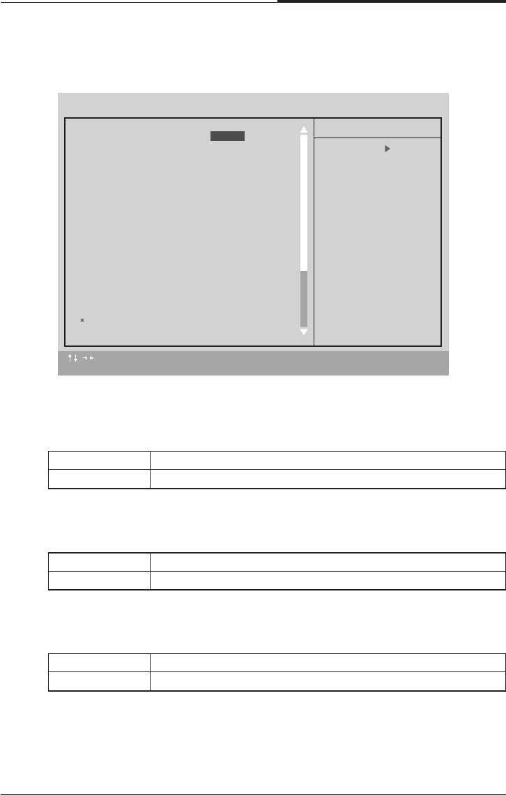
4.9 Power Management Setup
V/H SYNC+Blank BIOS will turn off V/H-SYNC when gets into Green Mode for Green
monitor power saving
Blank Screen BIOS will only black monitor when gets into Green Mode
DPMS BIOS will use DPMS| Standard to control VGA card (The Green type
VGA card will turn off V/H-SYNC automatically
●Video off In Suspend
The default value is Yes
●Suspend Type
The default value is Stop Grant
Yes Enabled Video off in suspend.
No Disable Video off in suspend.
Stop Grant Set Suspend type is stop grant
PwrOn Suspend Set Suspend type is Power on suspend.
:Move Enter : Select +/-/PU/PB : Value F10 : SAVE ESC : Exit F1 : General Help
F5 : Previous Values F6 : Fail-Safe Defaults F7 : Optimized Defaults
CMOS Setup Utility - Copyright (C) 1984-1999 Award Software
Power Management Setup
ACPI Suspend Type
Video Off Method DPMS
Video Off IN Suspend Yes
Suspend type Stop Grant
MODEM Use IRQ 4
Suspend Mode Disabled
HDD Power Down Disabled
Soft-Off by PWR-BTTN Instant-Off
Power LED in Suspend Blinking
AC BACK Function Memory
Wake-Up By PCI Card Enabled
ModemRingOn/WakeOnLan Enabled
FAN Off In Suspend Enabled
USB KB/Mouse Wake From S3 Disabled
CPU Thermal-Throttling 50.0%
Resume by Alarm Disabled
Date(of Month) Alarm 0
Time(hh:mm:ss) Alarm 0 0 0
Item Help
Menu Level
S1(PowerOn Suspend)

BIOS Configuration
4-19
CHAPTER 4
●Suspend Mode
The default value is Disable
●HDD Power Down
The default value is Disable
●Soft-off by PWR-BTTN
The default value is Instant-off
●Power LED in Suspend
The default value is Blinking
NA Set Modem Use IRQ to NA
3 Set Modem Use IRQ to 3
4 Set Modem Use IRQ to 4
5 Set Modem Use IRQ to 5
7 Set Modem Use IRQ to 7
9 Set Modem Use IRQ to 9
10 Set Modem Use IRQ to 10
11 Set Modem Use IRQ to 11
●MODEM Use IRQ
The default value is 4
Disable Disable SuspendModem Use IRQ to NA
1 min-1 Hour Setup the timer to enter Suspend Mode
Disable Disable SuspendModem Use IRQ to NA
1-15 mins Enable HDD Power Down mode between 1 to 15 mins
Instant Soft switch ON/OFF for POWER ON/OFF
Delay 4 Sec Soft switch ON 4 sec. For POWER OFF
Blinking Set Power LED in Suspend at Blinking mode
ON Set Power LED in Suspend at On mode
Off/Dual Set Power LED in Suspend at Off/Dual color mode

CHAPTER 4
4-20
BIOS Configuration
●Wake-Up By PCI card
The default value is Enabled
●Modem Ring On / Wake On Lan
The default value is Enabled.
●FAN Off In Suspend
The default value is Enable
●CPU Thermal-Throttling
The default value is Enable
Memory This function depends n computer status
Soft-Off Set System Soft-off Status
Full-On Set System Full-On Status
Disable Disable this function
Enable Enable wake-up by PCI card
●AC Back Function
The default value is Memory
Disabled Disable these functions
Enable Enable these functions.
Disable Disable this function
Enable Stop CPU FAN when entering Suspend mode
87.5% Monitor CPU Temp. will cause system slow down
CPU Duty Cycle to 87.5%
75.0% Monitor CPU Temp. will cause system slow down
CPU Duty Cycle to 75.0%
62.5% Monitor CPU Temp. will cause system slow down
CPU Duty Cycle to 62.5%
50.0% Monitor CPU Temp. will cause system slow down
CPU Duty Cycle to 50.0%
37.5% Monitor CPU Temp. will cause system slow down
CPU Duty Cycle to 37.5%
25.0% Monitor CPU Temp. will cause system slow down
CPU Duty Cycle to 25.0%
12.5% Monitor CPU Temp. will cause system slow down
CPU Duty Cycle to 12.5%

BIOS Configuration
4-21
CHAPTER 4
●Resume by Alarm
The default value is Disabled
IF the default value is Enabled
● Primary IDE 0/1
The default value is Disabled
● Secondary IDE 0/1
The default value is Disabled
● FDC/COM/LPT Port
The default value is Enabled
● PCI RIRQ [A-D] #
The default value is Enabled
Disable Disable this function
Enabled Enable alarm function to POWER ON system
Data (of Month) Alarm 0-31
Time (hh:mm:ss) Alarm (0-23) : (0-59) : (0-59)
Disable Disable this function
Enabled Enable monitor Primary IDE 0/1 for Green event.
Disable Disable this function
Enabled Enable monitor Secondary IDE 0/1 for Green event.
Disable Disable this function
Enabled Enable monitor FDC/COM/LPT for Green event.
Disable Monitor PCI PIRQ [A-D] IRQ Active
Enabled Ignore PCI PIRT [A-D] IRQ Active
CHAPTER 4
4-22
BIOS Configuration
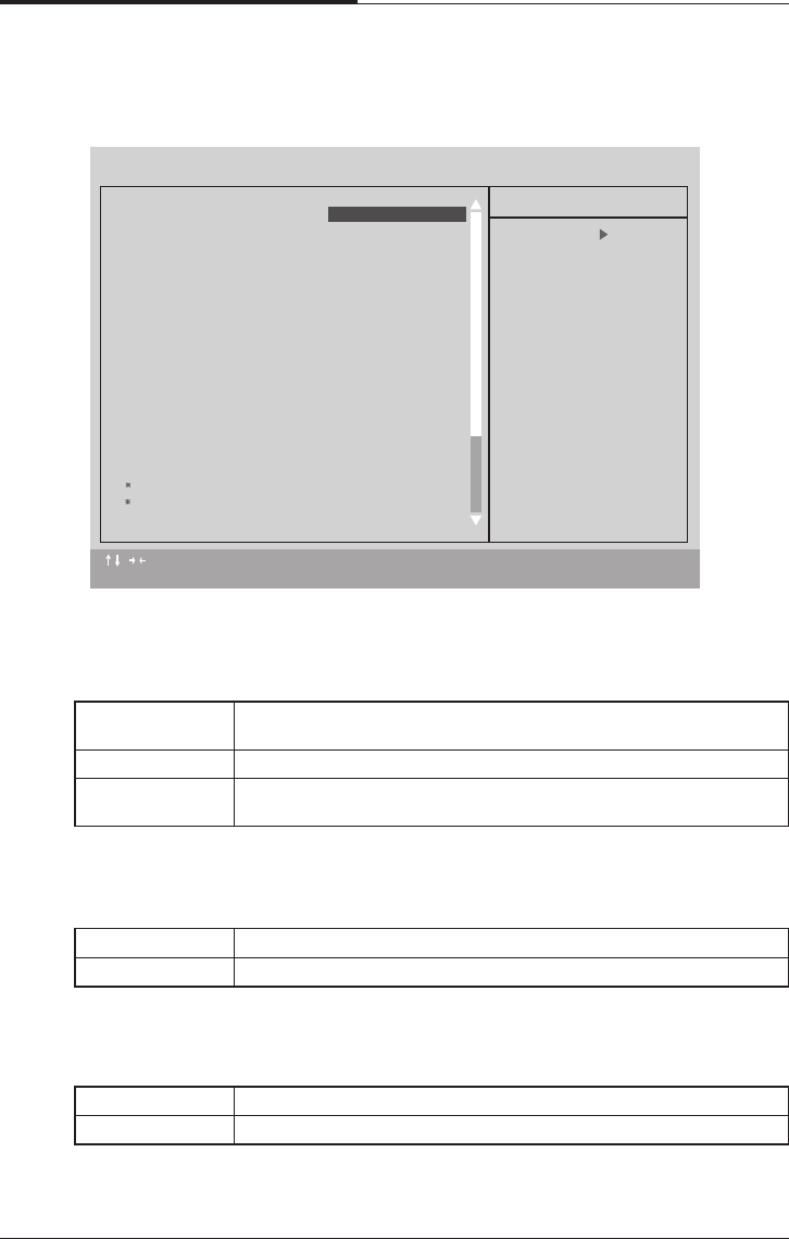
● PNP OS Installed
The default value is No
● Reset Configuration Data
The default value is Disable
4.10 PnP/PCI Configurations
Yes Enable PNP OS Installed function
No Disable PNP OS Installed function
Disable Disable this function
ESCD Enable clear PNP information in ESCD
DMI Reset Configuration Data in DMI
BOTH Reset Configuration Data DMI & ESCD
:Move Enter : Select +/-/PU/PB : Value F10 : SAVE ESC : Exit F1 : General Help
F5 : Previous Values F6 : Fail-Safe Defaults F7 : Optimized Defaults
CMOS Setup Utility - Copyright (C) 1984-1999 Award Software
PnP/PCI Configurations
PNP OS Installed
Reset Configuration Data Disabled
Resources Controlled By Auto [ESCD]
IRQ Resoarces Press Enter
DMA Resoarces Press Enter
PCI/VGA Palette Snoop Disabled
Item Help
Menu Level
Select yes if you are
using a plug and play
capable operating
system Select Mo if
you need the BIOS to
configure non-boot
devices
No

BIOS Configuration
4-23
CHAPTER 4
● IRQ(3,4,5,7,9,10,11,12,14,15) DMA(0,1,3,5,6,7) assigned to
The default value is "Legacy ISA" or "PCI/ISA PnP"
● PCI/VGA Palette Snoop
The default value is Disabled
Manual User can set the PnP resource (I/O Address, IRQ & DMA Channels)
used by legacy ISA DEVICE.
Auto BIOS automatically use these PnP rescuers
● Resources Controlled by
The default value is Auto (ESCD)
Legacy ISA The resource is used by Legacy ISA device.
PCI/ISA PnP BIOS automatically use these PnP rescuers.
Enabled For having Video Card on ISA Bus and VGA Card on PCI Bus
Disable For VGA Card only.
CHAPTER 4
4-24
BIOS Configuration
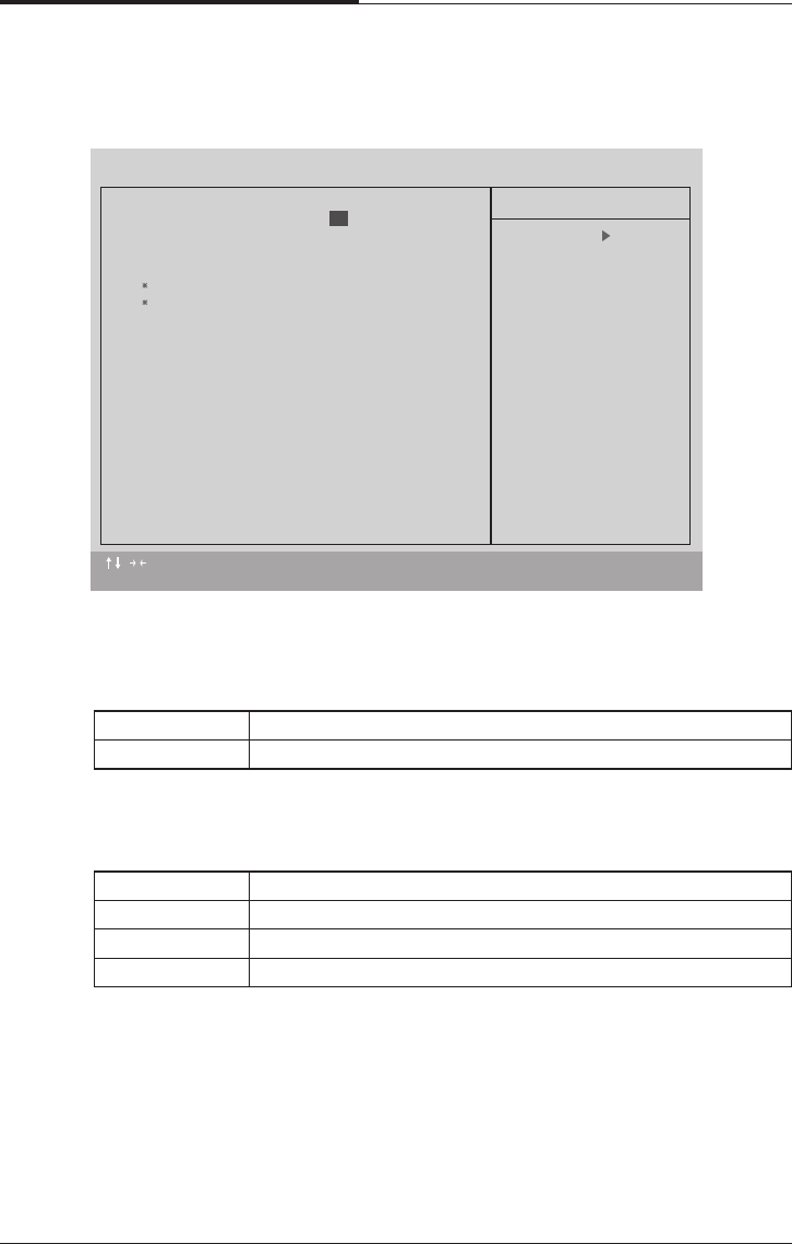
●Reset Case Open Status
●Case Opened
If the case is closed, “Case Opened” will show “No”
If the case have been opened “Case Opened” will show “Yes”
If you want to reset “Case Opened” Value, set “Reset Case Open Status”
To “Enabled” and save CMOS, your computer will restart.
●Current CPU Temperature
Detect CPU Temp automatically
●CPU FAN/Power FAN / System FAN Speed (RPM)
Detect FAN speed status automatically
●Current Voltage (V) VCORE /VGTL/VCC3/+_12V/+_5V/VBAT/5VSB
Detect system voltage status automatically
4.11 PC Health Status
:Move Enter : Select +/-/PU/PB : Value F10 : SAVE ESC : Exit F1 : General Help
F5 : Previous Values F6 : Fail-Safe Defaults F7 : Optimized Defaults
CMOS Setup Utility - Copyright (C) 1984-1999 Award Software
PC Health Status
Reset Case Open Status
Case Opened Yes
Carrent CPU Temperature 41 /105
CPU FAN Speed 4560 RPM
Power FAN Speed 0 RPM
System FAN Speed 0 RPM
VCORE 2.00 V
VGTL 1.50 V
VCC3 3.34 V
+5V 5.02 V
+12V 12.16 V
-12V -12.03 V
-5V -5.04 V
VBAT 3.18 V
5VSB 5.25 V
CPU Warning Temperature 70 /158
Shutdown Temperature 75 /167
CPU FAN Fail Alarm Disabled
Power FAN Fail Alarm Disabled
Item Help
Menu Level
Disabled

BIOS Configuration
4-25
CHAPTER 4
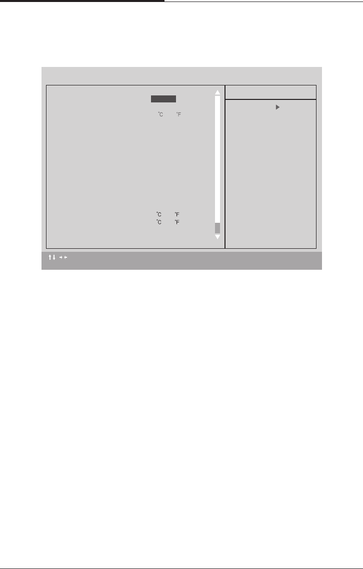
●Shutdown Temp
(This function will be effective only for the operating system that support ACPI
Function)
The default value is 90C / 194F
65c / 149F Monitor CPU Temp. at 65C / 149F
70c / 158F Monitor CPU Temp. at 70C / 158F
75c / 167F Monitor CPU Temp. at 75C / 167F
80c / 176F Monitor CPU Temp. at 80C / 176F
85c / 185F Monitor CPU Temp. at 85C / 185F
90c / 194F Monitor CPU Temp. at 90C / 194F
95c / 203F Monitor CPU Temp. at 95C / 203F
Disable Disabled this function
●CPU Warning Temperature
The default value is 80 C / 176 F
Disable Normal Operation.
65C/149F Monitor CPU Temp at 65C/149F, if Temp.>65C/149F
system will automatically power off.
70C/158F Monitor CPU Temp at 70C/158F, if Temp.>70C/158F
system will automatically power off.
75C/167F Monitor CPU Temp at 75C/167F, if Temp.>75C/167F
system will automatically power off.
80C/176F Monitor CPU Temp at 80C/176F, if Temp.>80C/176F
system will automatically power off.
85C/185F Monitor CPU Temp at 85C/185F, if Temp.>85C/185F
system will automatically power off.
90C/194F Monitor CPU Temp at 90C/194F, if Temp.>90C/194F
system will automatically power off.
●Fan fail Alarm (CPU/Power/System)
The default value is Disable
Disable Fan Fail Alarm Function Disable
Enable Fan Fail Alarm Function Enable
CHAPTER 4
4-26
BIOS Configuration
●Auto Detect DIMM/PCI Clk
The default value is Enable
●CPU Type CELERON (Depends on Your CPU Type)
1. System Bus Speed : 66MHz
200/233/266/300/366/400/433/500/533
2. System Bus Speed : 100MHz
300/350/400/450/500/550/600/650/700/750/800
3. System Bus Speed : 133MHz
400/466/533/600/666/733/800/866/933/1000/1066
4.12 Frequency/Voltage Control
Disable Disable Auto Detect DIMM/PCI Clk
Enable Enable Auto Detect DIMM/PCI Clk
:Move Enter : Select +/-/PU/PB : Value F10 : SAVE ESC : Exit F1 : General Help
F5 : Previous Values F6 : Fail-Safe Defaults F7 : Optimized Defaults
CMOS Setup Utility - Copyright (C) 1984-1999 Award Software
Frequency/Voltage Control
Auto Detect DIMM/PCI CIk
CPU Type CELERON(TM) 500
Item Help
Menu Level
Enabled
BIOS Configuration
4-27
CHAPTER 4
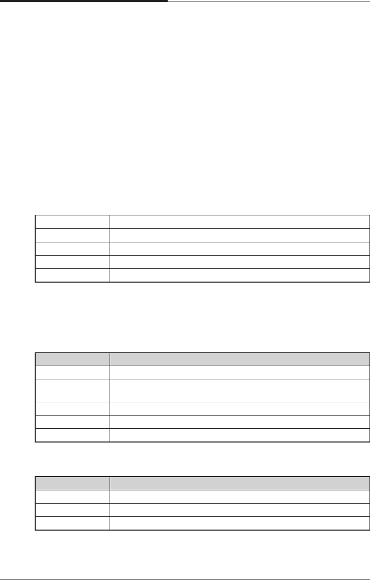
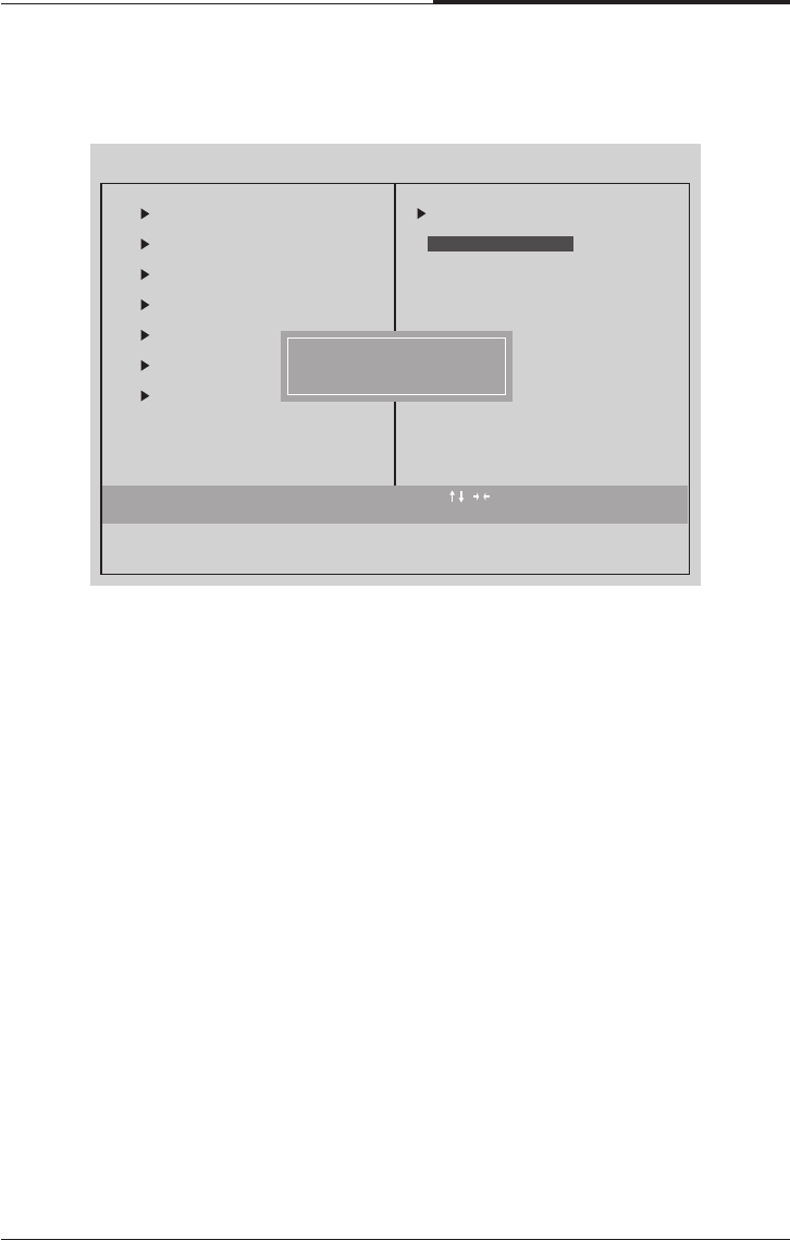
●Load Fail-Safe Defaults
Fail-Safe defaults contain the most appropriate values of the system
Parameters that allow minimum system performance
4.13 Load Fail-Safe Defaults
Esc : Quit : Select Item
F10 : Save & Exit Setup
CMOS Setup Utility - Copyright (C) 1984-1999 Award Software
Standard CMOS Features
Advanced BIOS Features
Advanced Chipset Features
Integrated Peripherals
Power Management
PnP/PCI Configuration
PC Health Status
Load Fail-Safe Defaults
Frequency/Voltage Control
Load Optimized Defaults
Set Supervisor Password
word
etup
Saving
Load Fail-Safe Defaults (Y/N)? N
Load Fail-Safe Defaults
CHAPTER 4
4-28
BIOS Configuration
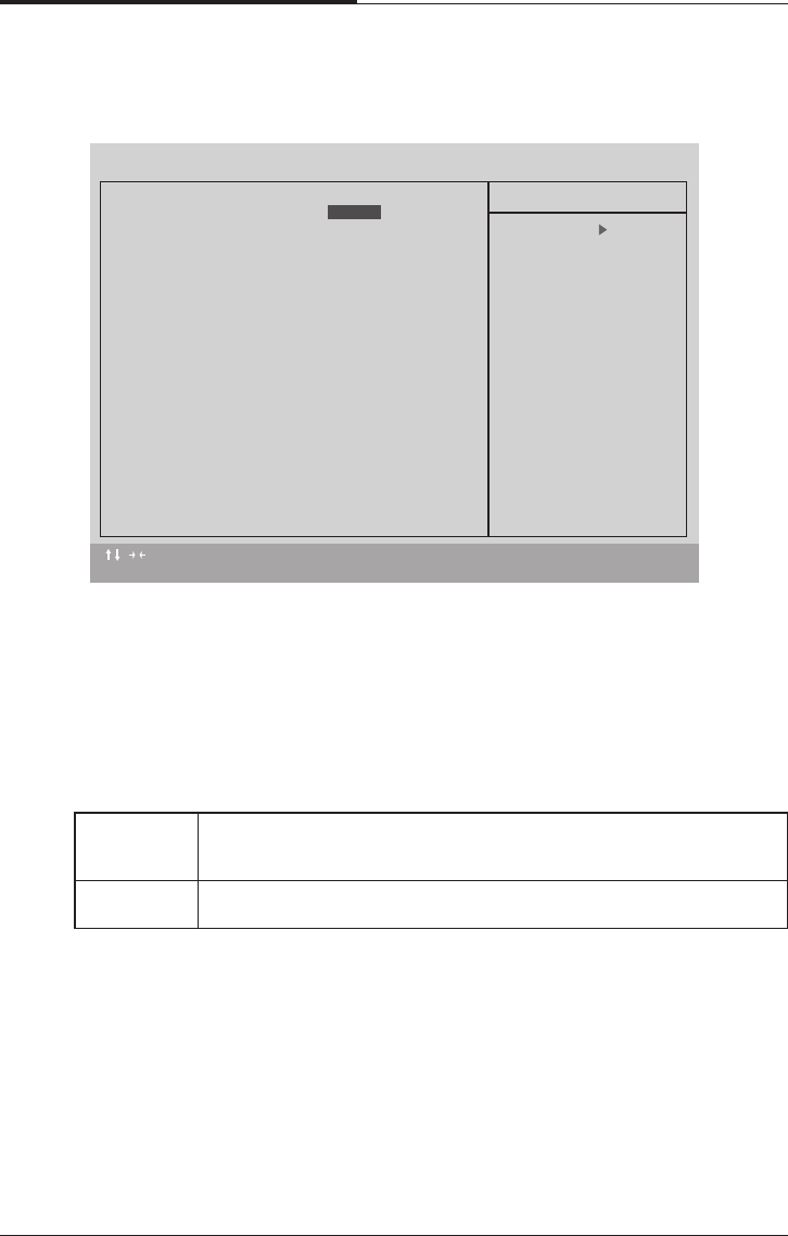
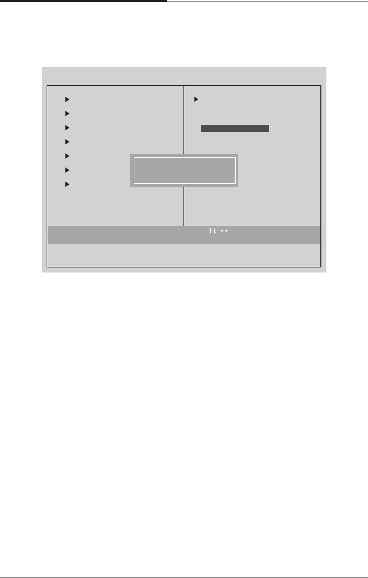
●Load Optimized Defaults
Selecting this field loads the factory defaults for BIOS and Chipset features
which the system automatically detects.
4.14 Load Optimized Defaults
Esc : Quit : Select Item
F10 : Save & Exit Setup
CMOS Setup Utility - Copyright (C) 1984-1999 Award Software
Standard CMOS Features
Advanced BIOS Features
Advanced Chipset Features
Integrated Peripherals
Power Management
PnP/PCI Configura
PC Health Status
Load Optimezed Defaults
Frequency/Voltage Control
Load Fail-Safe Defaults
Set Supervisor Password
word
etup
Saving
Load Optimized Defaults(Y/N)? N
Load Optimized Defaults
BIOS Configuration
4-29
CHAPTER 4
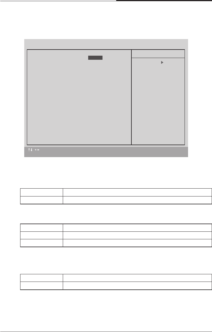
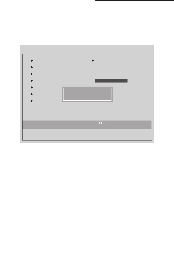
Type the password, up to eight characters, and press <Enter> key. The password
typed now will clear the previous entered password from CMOS memory. You will
be asked to confirm the password.
Type the password again and press <Enter> key. You may also press <ESC> key to
abort the selection and not enter a password.
To disable password, just press < Enter> key when you are prompted to enter
password. A Message “PASSWORD DISABLED” will appear to confirm the
password being disabled.
Once the password is disabled, the system will boot and you can enter Setup freely.
If you select system at Security Option in Bios Feature Setup Menu, you will be
prompted for the password every time the system is rebooted or any time you try to
enter Setup Menu. If you select Setup at Security Option in BIOS Features Setup
Menu, you will be prompted only when you try to enter Setup.
4.15 Set Supervisor / User Password
When you select this functions message will appear at the center of the screen to
assist you in creating a password
Esc : Quit : Select Item
F10 : Save & Exit Setup
CMOS Setup Utility - Copyright (C) 1984-1999 Award Software
Standard CMOS Features
Advanced BIOS Features
Advanced Chipset Features
Integrated Peripherals
Power Management
Pnp/PCI Configurations
PC Health Status
Save Date to CMOS
Frequency/Voltage Control
Load Fail-Safe Defaults
Load Optimized Defaults
word
etup
Saving
Enter Password?
Set Supervisor Password
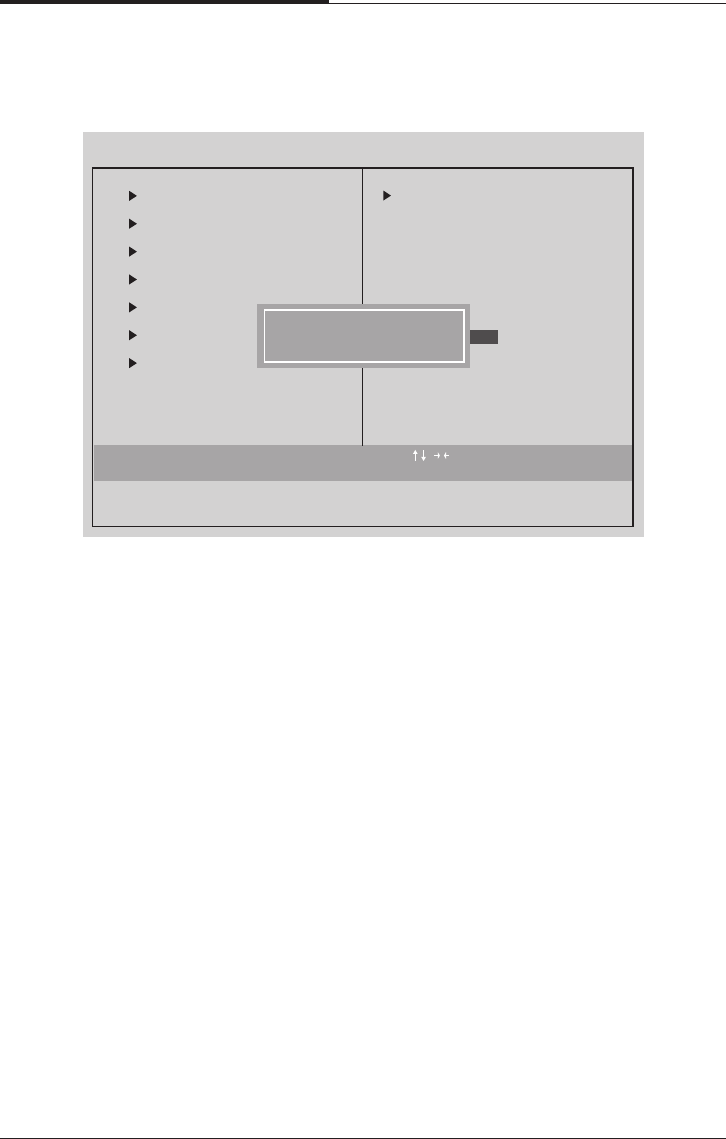
CHAPTER 4
4-30
BIOS Configuration
Type “Y” will quit the Setup utility and save the user setup value to RTC CMOS
Type “N” will return to setup utility.
4.16 Save & Exit Setup
Esc : Quit : Select Item
F10 : Save & Exit Setup
CMOS Setup Utility - Copyright (C) 1984-1999 Award Software
Standard CMOS Features
Advanced BIOS Features
Advanced Chipset Features
Integrated Peripherals
Power Management
PnP/PCI Configura
PC Health Status
Save Date to CMOS
Frequency/Voltage Control
Load Fail-Safe Defaults
Load Optimized Defaults
Set Supervisor Password
word
Saving
etup
SAVE to CMOS and EXIT (Y/N)?
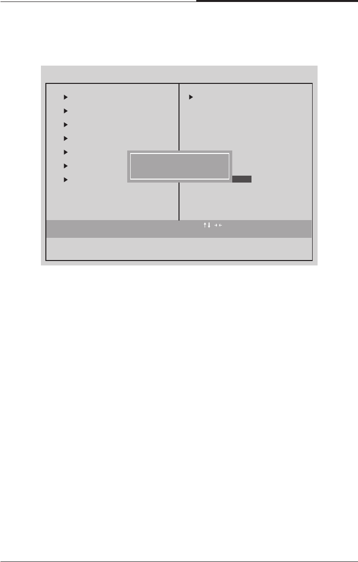
BIOS Configuration
4-31
CHAPTER 4
Type “Y” will quit the Setup utility without saving to RTC CMOS.
Type “N” will return to setup utility.
4.17 Exit Without Saving
Esc : Quit : Select Item
F10 : Save & Exit Setup
CMOS Setup Utility - Copyright (C) 1984-1999 Award Software
Standard CMOS Features
Advanced BIOS Features
Advanced Chipset Features
Integrated Peripherals
Power Management
PnP/PCI Configura
PC Health Status
Abandon all Batas
Frequency/Voltage Control
Load Fail-Safe Defaults
Load Optimized Defaults
Set Supervisor Password
word
etup
Saving
Quit Without Saving (Y/N)?

CHAPTER 4
4-32
BIOS Configuration
Blank
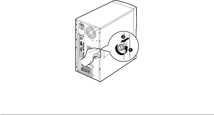
Inside Your Computer
5-1
Inside Your Computer
Chapter 5Chapter 5
Chapter 5Chapter 5
Chapter 5
Inside Your Computer
This chapter tells you how to remove and replace the system cover and connect the
internal cables, and familiarizes you with the internal components you might handle
if you install hardware options.
This chapter will be used every time you install a hardware option inside your
computer.
Removing the Cover
You need to remove the cover of your system to access its internal components.
To remove the cover, follow the below steps.
1. Turn off the computer and other peripheral devices including the monitor.
2. Disconnect all the cables include power cable from the computer.
3. To open the system cover, remove the one screw on the back panel of your
computer.
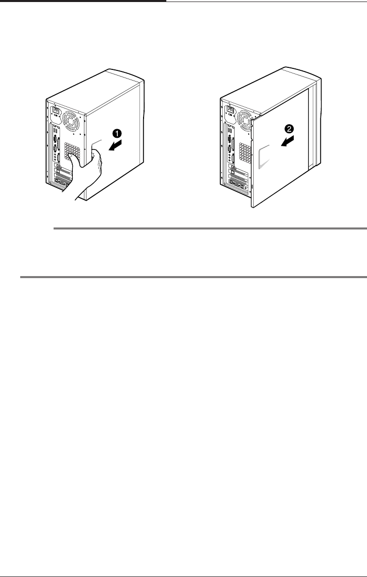
CHAPTER 5
5-2
Inside Your Computer
4. Slide the cover toward the rear to free it from the system and lift it off until can be
removed completely. Set the cover aside.
NOTE
Be sure to ground yourself by touching your system every time you remove the cover.
If you are not properly grounded, you could generate an electric shock when you
touch a component.
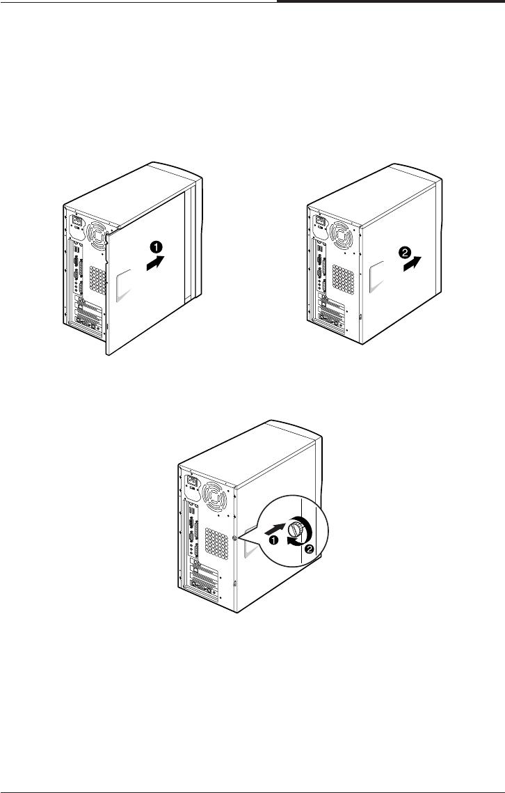
Inside Your Computer
5-3
CHAPTER 5
Replacing the Cover
Follow the below steps to replace the cover.
1. Hold the cover with your hands and gently put it down to the chassis on the rear
position (about 3cm) from the front bezel, then push it to the front.
2. Tighten the cover to the chassis with the screws you removed.
3. Reconnect the monitor, keyboard, mouse, and any other peripheral device’s cable
connectors to your system.
Reconnect all the device’s cable connectors to your system.
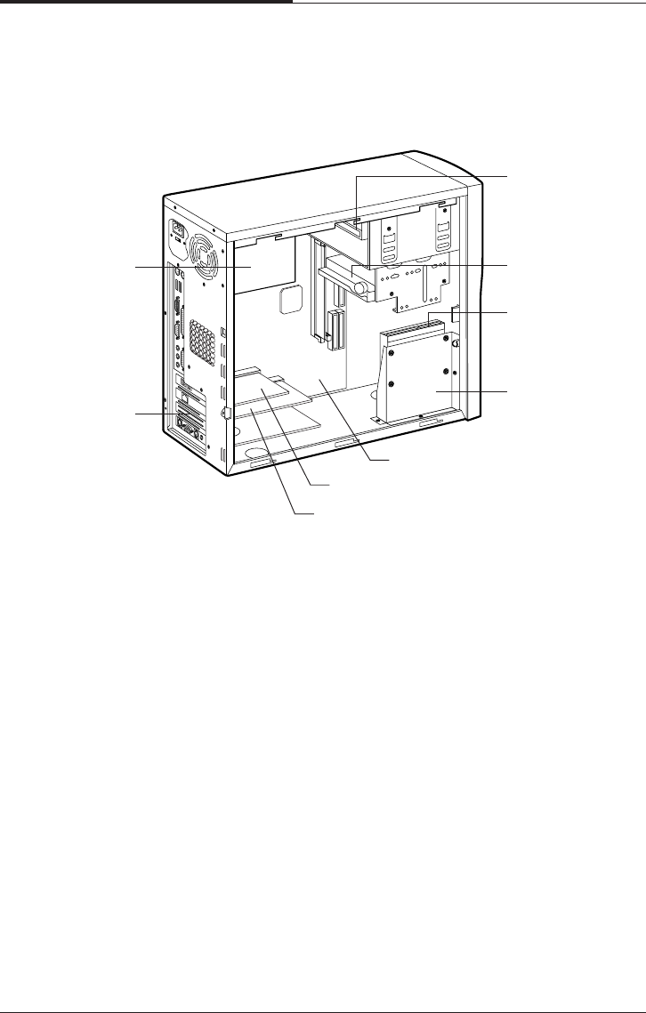
CHAPTER 5
5-4
Inside Your Computer
Internal Components
The following picture shows the components in your system.
Your computer has three (one 3.5-inch and two 5.25-inch) horizontal bays in the
drive cage and the HDD bracket for one hard disk drive.
Eathnet card
Power supply
Slot cover
Modem card
Mainboard
HDD bracket
Hard disk drive
3½ inch floppy
disk drive
CD/DVD/CDRW/
COMBO drive
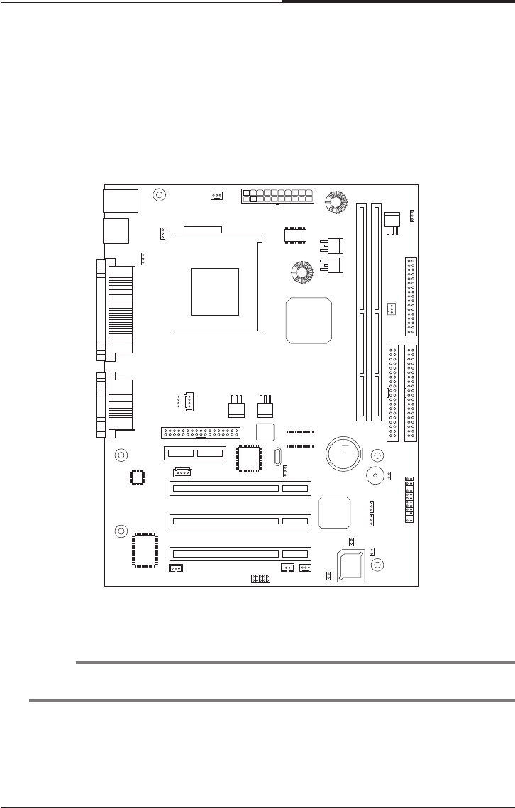
Inside Your Computer
5-5
CHAPTER 5
Mainboard Overview
The following picture shows the locations of the mainboard components in your
computer.
NOTE
The mainboard’s components may vary and look slightly different.
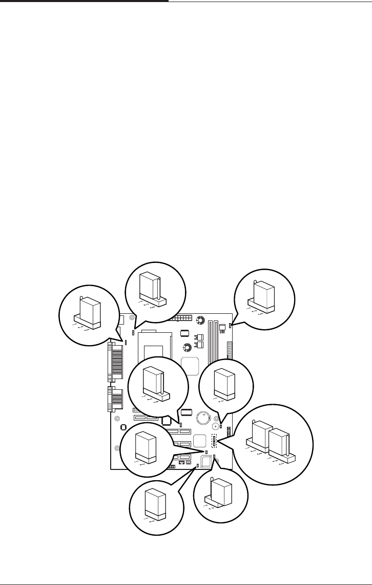
CHAPTER 5
5-6
Inside Your Computer
Changing the Jumpers
The jumpers are small electrical connectors that control various circuits or functions
in your system.
Jumpers are small blocks on a circuit board with two or more pins emerging from
them. To change a jumper setting, pull the plug off its pins and carefully fit it down
onto the pins indicated.
The jumpers settings in your computer are preset at the factory; however, you can
alter the functions by changing the standard settings:
●Enable or disable the password function.
●Clear the CMOS settings.
●Enable or disable the FDD write protect.
●Enable or disable the built-in display function.
JP1
J9
JP15
JP16
JP24
JP2 JP19
JP5
JP13
JP12
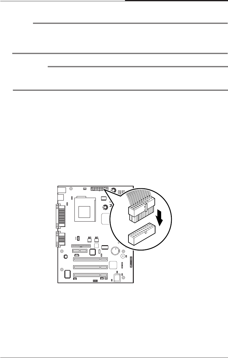
Inside Your Computer
5-7
CHAPTER 5
Connecting a Power Supply Connector
The power supply converts AC power to the DC voltage your computer needs. The
power supply has one big connector for mainboard and some other connectors for
devices such as hard disk, CD/DVD ROM, floppy disk drive, and etc in your
computer.
The cable of power supply having a big connector is connected to the power port on
the mainboard.
NOTE
The jumpers settings and their functions are inscribed on the label attached in your
system chassis. If you want to see the label, you need to remove the cover of your
system.
CAUTION
Do not change the jumpers with the power on. Always turn off the computer and
unplug the power cord from the computer before changing the jumpers.
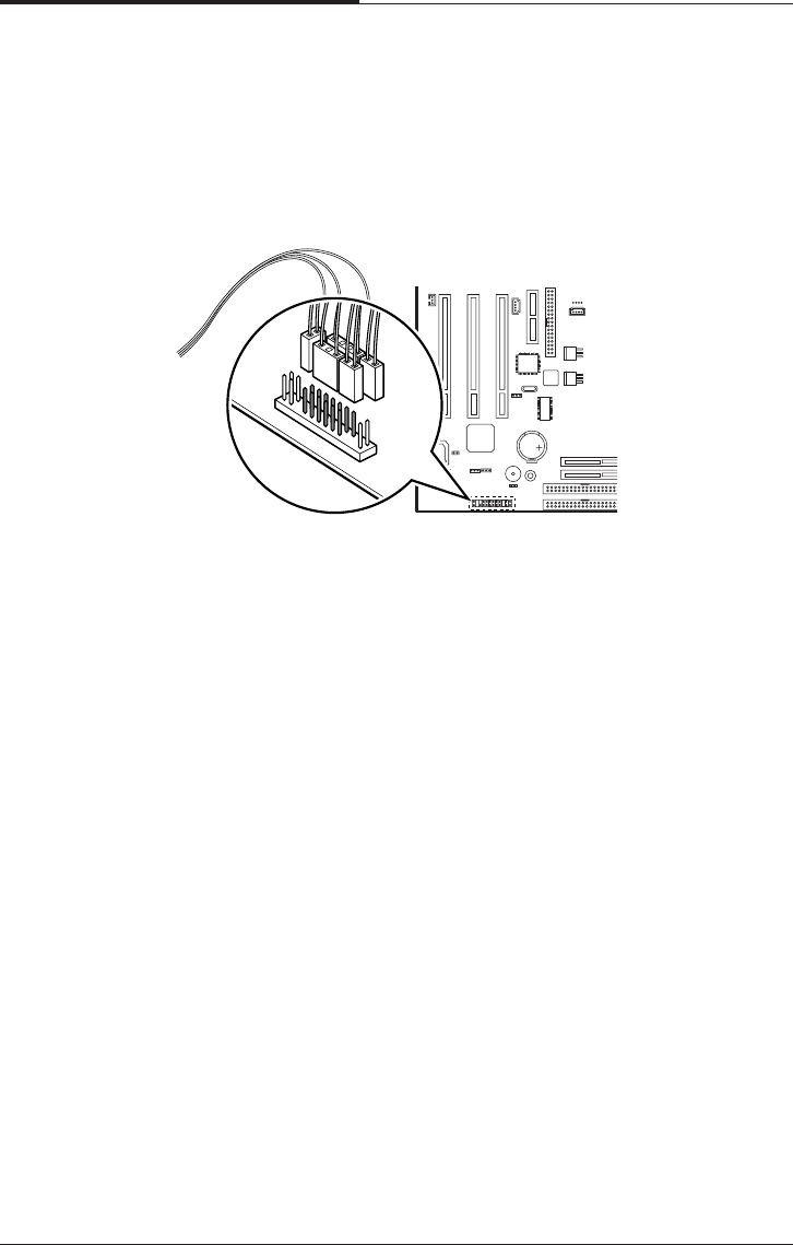
CHAPTER 5
5-8
Inside Your Computer
Connecting the Front Panel Connector
Cable
The front panel connector cable is connected to connectors on the mainboard and
front panel of your computer.

Installing and Removing Board Options and Drives
6-1
Installing and Removing
Board Options and Drives
Chapter 6Chapter 6
Chapter 6Chapter 6
Chapter 6
Installing and Removing
Board Options and Drives
This chapter describes how to install and remove optional drives and board options
in your computer. You can use these instructions to install and remove a variety of
devices and board options. Although your board options and drives may look a bit
different from the ones illustrated here, you can install and remove it the same way.
See Chapter 5 for removing and replacing the cover.
NOTE
Turn off the computer. Then disconnect the computer from its power source and
from any telecommunications links, networks, or modems before performing any of
the procedures described in this chapter.
Installing an Expansion Card
This section explains how to install an expansion card in your computer. Your
computer has three 32-bit PCI and one AMR connectors.
Follow the below steps to install an expansion card.
1. Remove the system cover according to the instructions in "Removing the Cover"
in Chapter 5.
2. Insert a flat blade screwdriver into a hole of the slot cover you wish to remove.
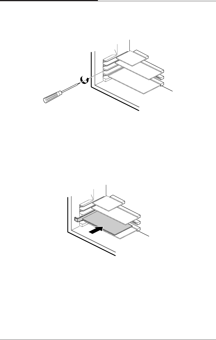
CHAPTER 6
6-2
Installing and Removing Board Options and Drives
4. If there is any switches or jumpers on the expansion card, adjust them. When you
handle the card, be careful not to touch any components or the gold edged
connector.
Push the expansion card connector in firmly to the connector on the mainboard.
The expansion
5. card connector must be fully inserted in the connector on the mainboard.
3. Move the screwdriver up and down until the slot cover breaks away from the
chassis. Then lift the slot cover out of the chassis
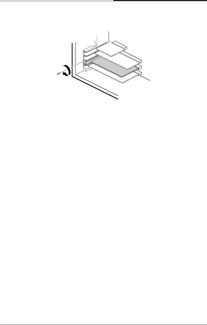
Installing and Removing Board Options and Drives
6-3
CHAPTER 6
7. Connect any cables if the expansion card has.
8. Replace the system cover according to the instructions in "Replacing the Cover"
in Chapter 5.
6. Secure the card with retaining screw to the computer.

CHAPTER 6
6-4
Installing and Removing Board Options and Drives
Installing and Removing Memory Modules
Your computer may have come with one memory module inserted into the
mainboard.
You can add a DIMM with the capacity of 16MB, 32MB, 64MB, or 128MB. You
can increase the amount of memory in your computer up to 256MB.
Each DIMM socket supports the following memory features:
●Unbuffered 168-pin 3.3 V DIMMs with gold-plated contacts
●SDRAM
●Single or double-sided DIMMs in the following sizes:
Installing a Memory Module
Follow the below steps to install DIMMs.
1. Remove the cover according to the instructions in "Removing the Cover" in
Chapter 5.
2. Install the DIMM in the socket marked with DIMM2, if the DIMM is installed in
the DIMM1 socket.
Press the clips at each end of the socket outward until they snap open.
3. Orient a DIMM to the socket so the two notches in the DIMM connector are
aligned with the crossbars in the socket.
DIMM size Non-ECC memory
16MB 2 Mbit * 64bit
32MB 4 Mbit * 64bit
64MB 8 Mbit * 64bit
128MB 16 Mbit * 64bit
256MB 32 Mbit * 64bit
512MB 64 Mbit * 64bit
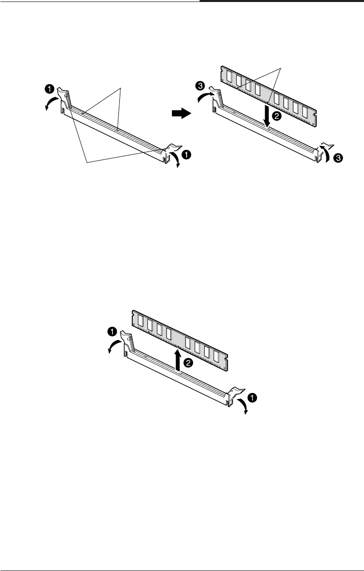
Installing and Removing Board Options and Drives
6-5
CHAPTER 6
4. Press the DIMM straight into the socket until the retaining clips snap into place
around the ends of the DIMM.
5. Replace the system cover according to the instructions in “Replacing the Cover”
in Chapter 5.
Removing a Memory Module
To remove memory modules, press the retaining clips outward simultaneously until
the DIMM disengages from the socket and then carefully remove the DIMM from
the socket.
Notches
Crossbars
Retaining clips
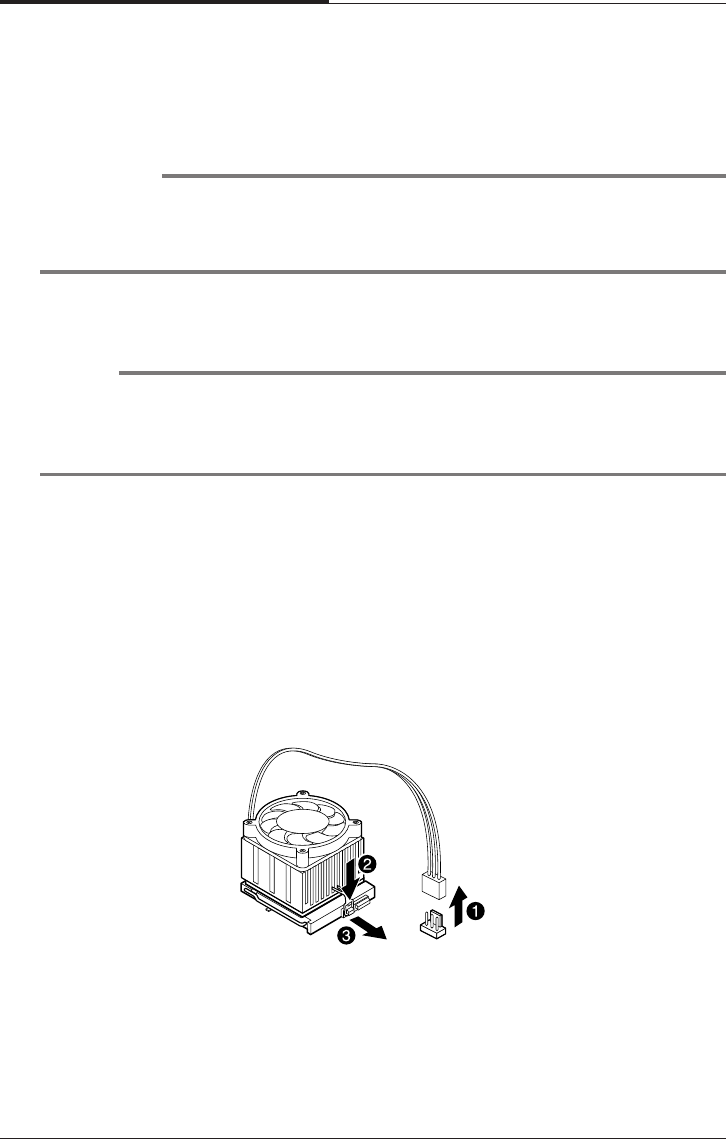
CHAPTER 6
6-6
Installing and Removing Board Options and Drives
Follow the below steps to replace the existing processor with a new one.
WARNING
The processor you want to install must have heatsink to prevent overheating. If
there is no heatsink, the processor and your mainboard can have serious damage by
overheat.
Installing and Removing the Processor
The processor that you install must be compatible with PGA370 socket.
NOTES
According to processor type, your actual process may be slightly different from one
described below.
There are two types, fan and heatsink type and heatsink type, of the processor.
1. Remove the system cover as described in "Removing the Cover" in Chapter 5.
2. See the picture in "Mainboard Overview" in Chapter 5 to figure out the location
of the processor socket.
3. If there is a processor chip on the socket, you must remove it from the socket.
When you remove the processor, first unplug the connector from the CPU fan
connector (fan and heatsink type only) and remove the heatsink by releasing both
tabs on the heatsink that secure the heatsink to the socket.
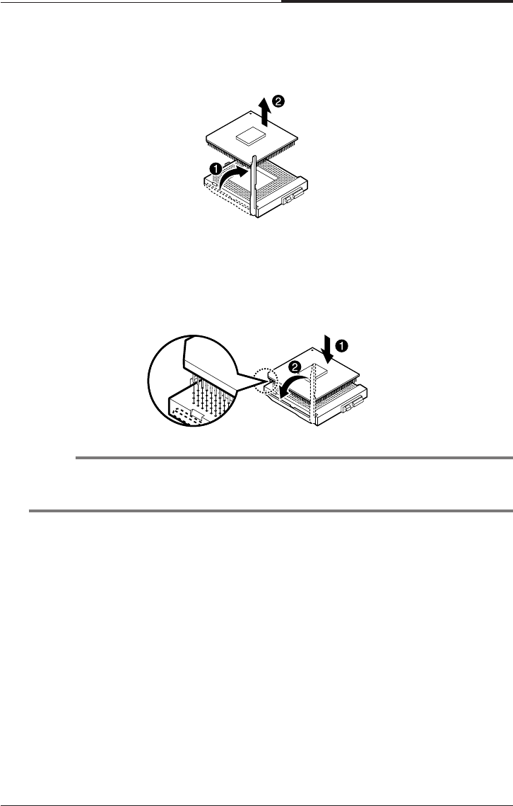
Installing and Removing Board Options and Drives
6-7
CHAPTER 6
5. Locate the new processor you are installing over the socket so that the notched
corner on the Processor (pin 1) can be aligned with the blank corner on the
socket. Then gently push the Processor straight into the socket until its pins are
completely inserted into the holes of the Socket.
4. Pull the ZIF handle sideways away from the socket then upward to 90-degree
angles and carefully pull the chip straight up from the socket.
NOTE
If you install the processor chip in the wrong orientation, you may burn the chip
and void your warranty.

CHAPTER 6
6-8
Installing and Removing Board Options and Drives
8. Replace the system cover according to the instructions in "Replacing the Cover"
in Chapter 5.
6. Press the ZIF handle back to close it.
7. Attach the heatsink to the processor socket. If your processor is fan and heatsink
type, connect a fan connector cable from the CPU fan to the CPU fan connector.

Installing and Removing Board Options and Drives
6-9
CHAPTER 6
Replacing a Hard Disk Drive
Your hard disk drive is installed in the HDD bracket attached on the chassis. You can
install one hard disk drive in the HDD bracket.
Follow the below steps to replace the hard disk drive.
1. Remove the system cover according to the instructions in "Removing the Cover"
in Chapter 5.
2. Detach all cables from the hard disk drive.
3. Remove the screw securing the HDD bracket to the computer. And then slide the
HDD bracket, as shown below.
4. Remove the screws from the HDD bracket.
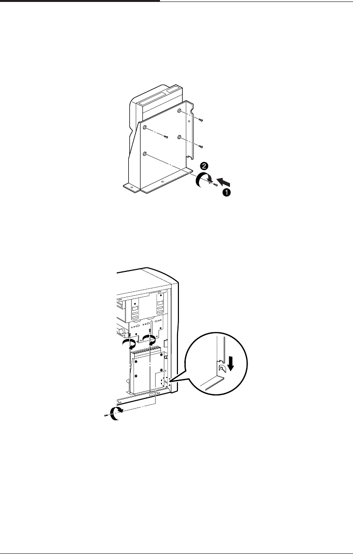
CHAPTER 6
6-10
Installing and Removing Board Options and Drives
7. Slide the drive until the four slots in the HDD bracket are inserted into the four
tabs of the chassis and then secure the HDD brakcet with the retaining screw, as
shown below.
5. Set the jumper of the new hard disk drive. If you want to install only hard disk
drive, the jumper setting must be master drive.
6. Using the screws, secure the hard disk drive to the HDD bracket.
8. Connect the free power cable and hard disk drive cable to the hard disk drive.
9. If you removed the hard disk drive cable from the mainboard, replace it.
10. Replace the system cover according to the instructions in "Replacing the Cover"
in Chapter 5.
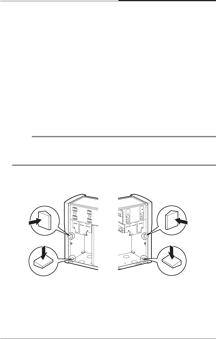
Installing and Removing Board Options and Drives
6-11
CHAPTER 6
Installing the 5.25-inch Device in the
Peripheral Bay
Your system has two 5.25-inch horizontal peripheral bays. If only one device (e.g.,
CD/DVD-ROM drive) is installed in the system’s 5.25-inch peripheral bay, you can
add an optional device such as a CD/DVD/CDRW/COMBO drive, hard disk drive,
LS-120 drive, or ZIP drive in the empty peripheral bay.
To install an optional device in the bay, follow the below steps.
1. Remove the cover according to the instructions in “Removing the Cover” in
Chapter 5.
2. Remove the HDD bracket from the system chassis. For more information, see
“Replacing a Hard Disk Drive” in this chapter.
3. Remove the front panel from the chassis by pressing the four tabs.
NOTE
If you want to install a 3.5-inch hard disk drive, you must purchase the 5.25-inch
dock or mounting bracket and attach it to your 3.5-inch hard disk drive to install
your hard disk drive for the 5.25-inch bay.
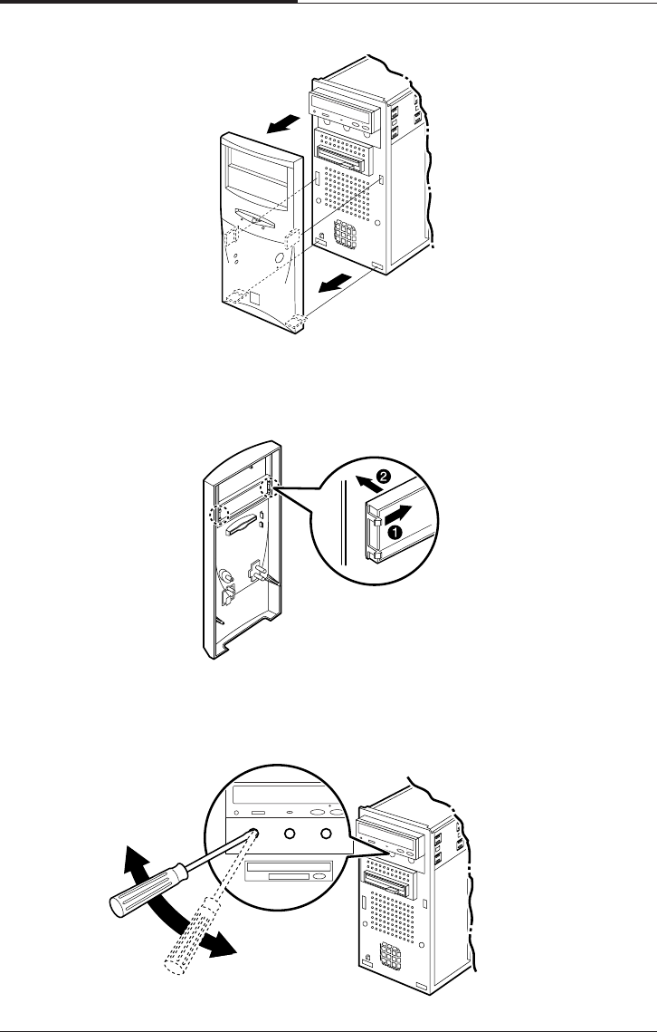
CHAPTER 6
6-12
Installing and Removing Board Options and Drives
4. Remove the faceplate cover from the front panel. Pull out the faceplate, pressing
outward each tab on both ends of the front panel using your finger.
5. If there is an EMI shield that covers the 5.25-inch drive bay you want to use,
remove it from the chassis using a tool such as a screwdriver.
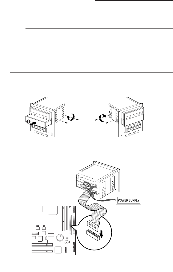
Installing and Removing Board Options and Drives
6-13
CHAPTER 6
6. Make you sure that jumpers of optional drive must be set correctly.
NOTE
As a hard disk drive, most optional devices’ jumpers must be set correctly to work
properly with your system. For example, if there are two drives to one E-IDE
interface cable, one drive must have master drive jumper setting, and the other
drive must have slave drive jumper setting.
If you want to install an optional drive to the 5.25 inch bay, you must use
secondary E-IDE drive connector. If your CD/DVD ROM is set to master, the
optional drive’s jumper must be set to slave.
7. Slide the device into the bay and secure it to the computer case with four screws.
8. Connect the power and interface cables to the device installed.
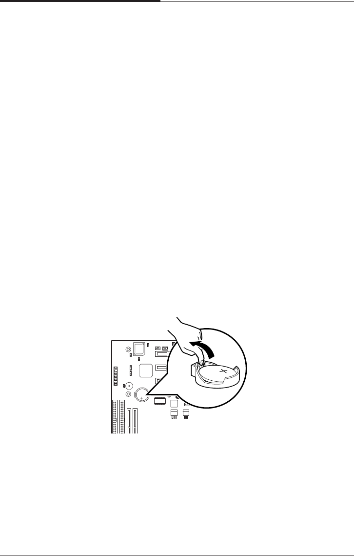
CHAPTER 6
6-14
Installing and Removing Board Options and Drives
9. To reassemble the front panel to the system, press the front panel toward the
system until the tabs on the front panel click into place.
10. Hook the front panel connector cable and replace the HDD bracket to the chassis.
11. Replace the system cover according to the instructions in "Replacing the Cover"
in Chapter 5.
Replacing the Battery
The 3 V, coin-cell CR2032-type battery on the mainboard provides power to the
real-time clock and CMOS RAM.
The battery approximately has three years lifetime when the system is off.
To replace the battery, follow the below steps.
1. Enter the Setup program and make a printed copy of the Setup screens.
2. Turn off your system and devices connected to the system.
3. Remove the system cover.
4. Take the battery out from the socket.

Installing and Removing Board Options and Drives
6-15
CHAPTER 6
6. Replace the system cover.
7. Turn on your system, run the Setup program, and set the date and time again.
Restore any system configuration information that was lost while replacing the
battery according to the copy made in step 1.
After Installing Options
After you install or remove drives, if necessary, be sure to run Setup program to
update the configuration of your system. See Chapter 4 for detail information.
If you installed a hard disk drive on which you want to install an operating system,
install the operating system, drivers, and application programs on the hard disk drive
using the Restore CD after running FDISK. Follow the instructions in Chapter 8.
If you installed a hard disk drive on which you want to install an operating system,
install the operating system on the hard disk drive. See "Using the Restore CD" in
Chapter 8.
If you installed new optional equipment and Windows ME is already installed in
your system, you need to have Windows ME detect it. See Windows ME manual and
the manual that came with your optional equipment for detail information.
5. Insert the new battery with the "+" side facing up into the battery socket.

CHAPTER 6
6-16
Installing and Removing Board Options and Drives
Blank

Application Programs
7-1
Application Programs
Chapter 7Chapter 7
Chapter 7Chapter 7
Chapter 7
Application Programs
Player
The Mpeg Player is the software application designed to work with your display
adapter.
The Mpeg Player supports full motion and full screen software MPEG video
playback with excellent video quality.
NOTE
The Player is available only on the CD-ROM drive model.

CHAPTER 7
7-2
Application Programs
AudioStation
AudioStation is a component audio system that can play or record audio CDs, digital
audio files (WAV or VOC), or MIDI files (MID, RMI or ORC). This consists of
Audio Mixer, CD Player, Digital Audio Player, and MIDI Player.
Audio Mixer lets you adjust the volumes of the various audio components and set
recording levels for digital audio. You can play audio CDs with the CD Player. You
can play digital audio (WAV) files with the Digital Audio Player and edit digital
audio files using WinDAT displayed by pressing the Edit button. With the MIDI
Player, you can play MIDI files. You can audition CD, WAV and MIDI files and
create custom playlists.
To run AudioStation program, point to program Voyetra after click the Start button,
and then click AudioStation.
NOTE
For more information, refer to on-line help. To see on-line help, click the icon on the
AudioStation screen.

Application Programs
7-3
CHAPTER 7
PowerDVD
Digital Versatile Disc (DVD) is a high-density storage device.
A standard DVD title can hold 4.7 gigabytes of data - a seven times the data capacity
of a current CD title.
Dual-layer DVD title can hold more than twelve times the information of a CD title
on a single side.
So you can enjoy higher-resolution pictures, more channels of digital sound, richer
graphics, and far more multimedia.
Playing the PowerDVD
If your DVD disc is auto-run, the PowerDVD will automatically start when you
insert the disc in the DVD-ROM drive.
For the DVD disc does not automatically start when you insert the disc, play the
PwerDVD as follows:
Double-click the PowerDVD icon on the desktop and press the play button on the
PowerDVD.
NOTE
The PowerDvD is available only on the DVD,COMBO drive model.
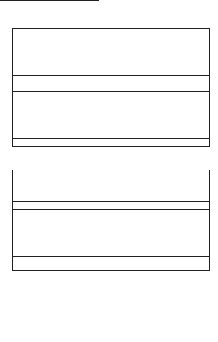
CHAPTER 7
7-4
Application Programs
The Main Controls
The Display Area
Ctel-N Minimizes user interface
Ctrl-X Exits PowerDVD
Z Zooms to full screen and to windows modes
O Denotes file mode, Press to switch modes
Ctrl-E Ejects discs from CD/DVD-ROM drive
F1 Accesses online help
+ Increases volume
- Mutes volume
Q Decreases volume
/ Menu pad used to navigate between DVD title menu selections
/ Number pad for entering numerical file or audio CD selections
N/A Click anywhere along the slider to navigate tithing a given chapter,
VCD, CD or file
DVD video is the current media
Digital files are the current media
VCD is the current media
Audio CD is the current media
Stereo is the current audio mode
Dolby os the current audio mode
4-speaker is the current audio mode
6-speaker is the current audio mode
SPDIF is the current audio mode
Denotes current drive
Denotes current subtitle
Denotes current audio stream
Denotes current region
Denotes current angle
Denotes current parental control

Application Programs
7-5
CHAPTER 7
The Control Wheel
1. 8X Reverse ( )
2. 4X Reverse ( )
3. 2X Reverse ( )
4. 1X Reverse ( )
5. Pause ( )
6. 1X Forward ( )
7. 2X Forward ( )
8. 4X Forward ( )
9. 8X Forward ( )
The Control Panel
NOTE
The green point roughly marks the shuttling above.
Forward speeds of 1/2X, 1.5X, 3Xand 6X and 1/2X rewinding speed are not
pictured Above but are sequentially located between their respective locations above.
Enter Play DVD, VCD, CD or files
Space Bar Pauses playback
S Stops playback
N Jumps to next chapter
P Returns to previous chapter
Ctrl-B Steps backward one frame
T Steps forward one frame

CHAPTER 7
7-6
Application Programs
Hidden Control Panel
Disc Mode

Application Programs
7-7
CHAPTER 7
<Region Code for Area>
File Mode
K Switches among karaoke mode
C Captures video content as bitmap image file
A Switches among available angles
R Goes ip to previous section when navigation
DVD title menu selections
X Sets A and B Points to repeat specific user-defined
Scenes during playback
H Switches among available audio streams
Ctrl+R Repeats titles, chapters or screens
U Switches among available subtitle during playback
L Accesses all available menus
Ctrl+F2 Bookmarks specific scenes in DVD
F2 Directly goes to bookmarked scenes
F3 I-Power takes you to the Internet directly
Ctrl-C Configuration setting is all located here
U shuffles playlist in File mode
NOTE
Your PowerDVD application is already set to Region 1, so you can play the DVD
disc that contains no region code or a Region 1 code.
Region No. Area
Region 1 The United States, U.S. Territories and Canada.
Region 2 Europe, The Middle East, Japan and South Africa.
Region 3 Asia Pacific.
Region 4 South America and Australasia.
Region 5 Russia, Eastern Europe, Central Asia and Africa.
Region 6 China.

CHAPTER 7
7-8
Application Programs
Blank

Using the Restore CD
8-1
Using the Restore CD
Chapter 8Chapter 8
Chapter 8Chapter 8
Chapter 8
Using the Restore CD
Use the Restore CD for the following:
●To restore all software including Windows ME.
●To restore lost or destroyed drivers or application programs.
Restoring Your Original Software
The Restore CD contains a copy of all software (e.g., Windows ME, drivers, and
application programs) originally preinstalled on your hard disk. (This process may
take about 20 minutes.)
There are two ways to restore the software:
●You can restore the software that came with your system without formatting the
hard disk.
WARNING
You must reinstall any software not originally installed on your hard disk drive.
WARNING
If you format your hard disk, you lose all data that added files, programs, or other
data on your hard disk since you purchased your system. If you must reinstall any
software not originally installed on your hard disk and don’t want to lose your
personal data on your hard disk, copy it to diskettes before formatting.
● You can format the hard disk and then restore all original software.

CHAPTER 8
8-2
Using the Restore CD
follow the below steps to restore your original preinstalled software.
1. Turn on the computer.
2. Insert the Restore CD into the CD/DVD-ROM drive before your computer boots
up.
3. Restoration procedures will be started.
4. When the Microsoft Windows ME Startup Menu appears, type the number 1 or 2
and press Enter.
Microsoft Windows Startup Menu
1 RESTORE WINDOWS - WILL FORMAT HDD
2 RESTORE WINDOWS - WILL NOT FORMAT HDD
3 BOOT TO DOS PROMPT FROM CD-ROM
Enter a choice : _
5. If you select “1. RESTORE WINDOWS ME - WILL FORMAT HDD,” the
“Proceed with Format (Y/N)?” message will appear in the screen. To continue the
procedures, type Y and press Enter.
6. All data in the Restore CD will be copied to your hard disk.
7. After the restoration process is completed, remove the Restore CD from your
CD/DVD/CDRW/COMBO drive.
8. Press Enter to restart your computer.
CAUTION
If you select "1. RESTORE WINDOWS 98 - WILL FORMAT HDD," you will
lose all data in the hard disk (C:).
NOTE
To stop this restore process now, remove the Restore CD from the CD/DVD-
ROM drive and restart your computer.

Using the Restore CD
8-3
CHAPTER 8
9. Windows ME starts and the registration program runs.
10. To register with Microsoft for using your computer, follow the displayed
messages. Enter your personal information and the Windows ME Product Key
(attached on the Windows 98 manual).
Installing Drivers or Application Programs
If you lose a driver or application program, install it by using the Restore CD that
came with your system.
follow the below steps to install drivers or application programs.
1. Insert the Restore CD into the CD/DVD/CDRW/COMBO drive when Windows
ME is started.
2. Double-click the My Computer icon on the desktop.
3. Double-click the CD-ROM icon in the My Computer window.
4. Double click the SETUP.EXE icon in CD ROM folder to start the Driver &
Software installation program.
5. Click a driver or application program menu to install or copy to your system.
Also you can see all directories in the Restore CD by clicking the Browse this
CD menu.
NOTE
If the Restore CD is in the CD/DVD-ROM drive while your computer is booting,
the computer will be booted with the Restore CD. In this case, the "Microsoft
Windows ME Startup Menu" menu will appear. To continue the restoration,
remove the Restore CD from your CD/DVD-ROM drive and restart the
computer.
NOTE
If you move the mouse pointer to a menu title in the installation program
window, the color of the menu will be changed.
6. Follow the instructions on the screen.

CHAPTER 8
8-4
Using the Restore CD
Blank

Specifications
A-1
Specifications
Appendix AAppendix A
Appendix AAppendix A
Appendix A
Specifications
Feature Specifications
Processor • Intel Celeron processor in a PPGA package
• Intel Pentium III processor in a PPGA package
• 66/100/133 MHz bus speed
• Auto Detect CPU Voltage.
Memory Main Memory
• Two 168-pin 3.3 V DIMM sockets
• Supports up to 512 MB memory
• Unbuffered Synchronous DRAM (SDRAM)
Intel 810 Intel 82810 PCI/A.G.P. controller (PAC)
AGPset • Intel 810 AGPset; AC 97
• Integrated Accelerated Graphics Port (A.G.P.) controller
SLOT • 1 X AMR (Audio Modem Rise) Slot
• 3 X PCI Solt Supports 33MHz & PCI 2.2 compliant
I/O • 2 X Ultra DMA 33/66 Bus Master IDE ports on board
• 1 X FDD, 1 X COM, 1 X LPT, PS/2 keyboard, PS/2 Mouse on board
• 1 X VGA(DB15), 1 X Joystick, 1 X Line-in, 1 X Line-out
? 1 X MIC on board
• 2 X USB ports on board
Power • ATX Power connector
• Power-on by Keyboard, PS/2 Mouse, LAN, RTC, Modem & Switch
• Power-off by Windows R 95/98/ME Shut & Switch
• Suspend / Wake-on by ACPI & APM device
• AC Recovery ON/OFF control; 3 Level ACPI LED
• Stop CPU Fan during entering suspend mode
From FACTOR/PCB • Micro ATX, 4 layer PCB
H/W Monitoring • Auto speed down and Alarm when CPU overheat of Fan failure (OS
? independent & Driverless)
• 3 Fan Power & Speed Detection Connectors; Case open Detection
• System Health status detect & report by BIOS, LDCM & SIV
• H/W detect +/-5V, +/-12V, CPU Voltage & CMOS battery Status
BIOS • 4Mbit Flash RAM
• AWARD BIOS with Enhanced ACPI Feature for PC98/ Win98 Compliance,
? Green, PnP, DMI, INT13 (>8.4GB) & Anti-Virus functions
• IDE#1~#4, SCSI, LS120, ZIP & CD-ROM bootable
• Auto-detect & report system health status
Other Features • Suspend-To-RAM (STR)
• Includes Wake-On-LAN Header (WOL)
• Includes Wake-On Ring (WOR)
• Poly fuse for keyboard, USB, VGA & Game overcurrent protection

APPENDIX A
A-2
Specifications
Blank

Solving Common Problems
B-1
Solving Common Problems
Appendix BAppendix B
Appendix BAppendix B
Appendix B
Solving Common Problems
This chapter instructs you how to deal with the problems you might experience
when using your computer. The problem is listed first, followed by the solution.
Read it before calling a technician if a problem occurs.
Power
Hard Disk Drive
Cause Solution
My computer Computer is not properly connected to a grounded wall outlet.
doesn’t work Make sure the power cord is firmly plugged into the wall outlet and into
the Wall outlet is not working.
To check to see whether the wall outlet works, plug other device (such
as a lamp) into the wall outlet. If it is not working, use other wall outlet.
When the computer turned down by sudden power failure, it will not
operate if you press the power button. To turn on the computer, refer to
the followings:
Unplug the power cord to turn off your computer and wait about 10
seconds for complete discharge and re-plug the power cord. Then
press the power button.
Cause Solution
Hard disk drive The files stored on your hard disk may be fragmented.
operation seems Check for lost allocation units by running Disk Defragmenter. (For slow
more information, refer to the Windows 98 manual that came with your
computer.)
Hard disk drive The files stored on your hard disk may be corrupted.
access indicator Check for lost allocation units by running Disk Defragmenter. (For more
light stays on information, refer to the Windows 98 manual that came with your
computer.)

APPENDIX B
B-2
Solving Common Problems
Cause Solution
The CD/DVD-ROM CD/DVD is not properly seated in the CD/DVD-ROM drive.
drive cannot read Eject the CD/DVD, gently but firmly press down on the CD/DVD to seat
CD/DVD it in the drive, then reload.
Your CD/DVD-ROM drive is not recognized.
Turn off the computer, wait at least 30 seconds, and then turn on the
computer.
CD/DVD has been inserted upside down.
Eject the CD/DVD, turn it over, then reload. (The label on the CD/DVD
should be facing up.)
CD/DVD is dirty.
Clean the CD/DVD with a CD/DVD cleaning kit (available in computer
stores).
CD/DVD is defected.
Try another CD/DVD. If it operates well, the CD/DVD is defected.
How to use the CD/DVD-ROM drive in Real MS-DOS mode?
If you reboot your computer by selecting “Restart in MS-DOS mode”
option in “Shut Down Windows,” you can use the CD/DVD-ROM drive.
However, to use the CD/DVD-ROM drive in real MS-DOS mode, manually
delete the “REM” of the line “REM Mscdex /d:gem001” in the
AUTOEXEC.BAT file.
<AUTOEXEC.BAT>
...
REM [CD-ROM DRIVE]
Mscdex /d:gem001
...
The DVD-ROM drive The high speed DVD-ROM drive takes few seconds to stop the running
takes about 5 to 10 of the spindle motor when you press the eject button, immediately after
seconds to open using CD or DVD, to open the tray.
the tray when I press Wait about 5 to 10 seconds after pressing the eject button to give the
the eject button DVD sufficient time to stop the running of the spindle motor and eject
the tray.
CD/DVD-ROM Drive

Solving Common Problems
B-3
APPENDIX B
Audio
Floppy Disk Drive
Cause Solution
How do I control To control the audio volume level, use the volume control box.
the audio volume Click on the Speaker icon located on the right of your Windows taskbar.
When the level? volume control box appears, drag the volume bar up or down to adjust
the audio volume level.
To control the audio volume level for each device, use the Master Out
window.
Double-click the Speaker icon located on the right of your Windows
taskbar. When the Master Out window appears, in the each device
area, drag the volume bar up or down to adjust the audio volume level.
Computer doesn’t Audio has been muted.
make any sound Click on the Speaker icon located on the right of your Windows taskbar.
When the volume control box appears, verify that the Mute option
check box is empty.
Volume is turned down.
The volume level may be too low. Click on the Speaker icon located on
the right of your Windows taskbar. When the volume control box
appears, drag the volume bar upward.
The speakers are not properly connected.
Make sure that the speakers are properly connected to the computer.
Cause Solution
Floppy disk drive Disk is incorrectly inserted.
light stays on Remove the disk and reinsert it.
Disk is damaged.
Use another disk or check the disk by running ScanDisk. (For detail
information, refer to your Windows 98 manual.)
Floppy disk drive Disk is unformatted.
can’t write to a Format the disk (Refer to your Windows Help in Windows 98. To open
disk Windows Help, click the Start button, and then click Help.)
Disk is write-protected.
Remove the write-protection or use another disk that is not
write-protected. To remove write-protection from a disk, slide the small
black tab on the back of the disk to cover the hole.
Floppy disk drive Disk is unformatted.
can’t read the Format the disk. (Refer to your Windows Help in Windows 98. To open
diskeete Windows Help,click the Start button, and then click Help.)

APPENDIX B
B-4
Solving Common Problems
Display & Monitor
Cause Solution
The monitor doesn’t The brightness and contrast controls aren’t set properly
work Adjust the brightness and contrast controls on the monitor.
The cable connecting the monitor to your computer isn’t connected
properly.
Make sure that the monitor connector is properly and securely
connected to the video connector of your computer.
Monitor is not properly connected to a grounded wall outlet.
Make sure the power cord is firmly plugged into the wall outlet and into
the monitor.
You have a screen blanking utility installed or your computer entered
power management mode.
Press any key or move your mouse. Your current screen will reappear.
How do I change To change the display resolution or color depth, use the Display
the display Properties window.
resolution or color To change the display resolution and color depth, follow these steps:
depth? 1. Click the Start button, point to Settings, click Control Panel, and then
double click the Display icon. Or click the right mouse button on the
empty desktop area and click Properties.
2. When the Display Properties window appears, click the Settings tab.
3. Select the color depth from the Colors area and the resolution from
the Screen area. Click OK.
4. If you changed color depth, the system would reboot. If you
changed resolution only, the screen will be changed to the new
settings.
How do I use the old (existing) monitor that doesn’t support
the factory default display setting (SVGA mode, 800*600)?
To use the old (existing) monitor, you must start Windows in safe mode, and then set
the resolution and color depth as follows:
1. Press the power button to start your system.
2. Press and hold the F8 key until the Microsoft Windows 98 Startup Menu appears.

Solving Common Problems
B-5
APPENDIX B
3. Enter the number for Safe mode, and then press ENTER.
Microsoft Windows Startup Menu
1. Normal
2. Logged (\BOOTLOG.TXT)
3. Safe mode
4. Step-by-step confirmation
5. Command prompt only
6. Safe mode command prompt only
Enter a choice : 3
4. Click OK in the Desktop window.
5. In the Windows desktop, click the Start button, point to Settings, click Control
Panel, and then double-click the Display icon. Or click the right mouse button on
the empty desktop area and click Properties.
6. When the Display Properties window appears, click the Settings tab.
7. Click OK.

APPENDIX B
B-6
Solving Common Problems
10. If the Windows screen doesn’t appear on the monitor after restarting, turn off the
computer and follow these steps.
11. Repeat the steps from 1 to 6.
12. Click Advanced.
13. Click the Adapter tab.
14. Click Change.
15. When the Update Device Driver Wizard window appears, click Next.
16. Check the "Display a list of all the drivers in a specific location, so you can select
the driver you want." option and click Next.
17. Select the Display adapters item in the list box and click Next.
18. Select the "Standard display types" menu in the Manufacturers list box and select
the model for your system in the Models list box. Then click Next.
19. Click Yes.
20. Click Next.
21. Click Finish.
22. Click Close.
23. Click Close in the Display Properties window.
24. Click Yes to continue.
25. Click Yes to restart your computer.
8. Click Yes to continue.
9. Click Yes to restart your computer.
NOTE
In case your existing monitor supports higher resolutions or color depths than
640*480 and 16 Colors, change the resolution and color depth after restarting.

Solving Common Problems
B-7
APPENDIX B
Keyboard
Mouse
Cause Solution
Keyboard doesn’t Keyboard isn’t firmly or securely connected to the keyboard connector.
work Check that the keyboard is connected to the keyboard connector on
the back of your computer, not the mouse connector.
Option Card
Cause Solution
Mouse doesn’t work Mouse isn’t firmly or securely connected to the mouse connector.
Check that the mouse is connected to the mouse connector on the
back of your computer, not the keyboard connector.
Mouse needs cleaning.
To clean the mouse ball, remove the mouse ball by unscrewing the
bottom of the mouse. Then clean the mouse ball with a damp cloth
and replace the mouse ball.
Cause Solution
After you add a PCI Your computer can’t recognize the option card.
option card in the To recognize the option card, follow these steps:
empty slot or 1. Click the Start button, and then point to Settings.
change the slot 2. Click Control Panel.
location of your PCI 3. Double-click the System icon.
option card, your 4. Click the Device Manager tab in the System Properties window.
computer isn’t 5. Click the Refresh button. This option updates the hardware list. This
working properly process may take a few minutes.

APPENDIX B
B-8
Solving Common Problems
Blank

Approval Statements
C-1
Approval Statements
Appendix CAppendix C
Appendix CAppendix C
Appendix C
Approval Statements
FCC Compliance Statement
This equipment has been tested and found to comply with the limits for a class B
digital device, pursuant to Part 15 of the FCC Rules. These limits are designed to
provide reasonable protection against harmful interference in a residential
installation. This equipment generates, uses, and can radiate radio frequency energy
and, if not installed and used in accordance with the instructions, may cause harmful
interference to radio and television reception. However, there is no guarantee that
interference will not occur in a particular installation. If this equipment does cause
interference to radio and television reception, which can be determined by turning
the equipment off and on, the user is encouraged to try to correct the interference by
one or more of the following measures:
●Reorient or relocate the receiving antenna.
●Increase the separation between the equipment and receiver.
●Connect the equipment into an outlet on a circuit different from that to which the
receiver is connected.
●Consult the dealer or an experienced radio/TV technician for help.
Warning
The connection of a non-shielded equipment interface cable to this equipment will
invalidate the FCC Certification of this device and may cause interference levels that
exceed the limits established by the FCC for this equipment. It is the responsibility
of the user to obtain and use a shielded equipment interface cable with this device. If
this equipment has more than one interface connector, do not leave cables connected
to unused interfaces.
Changes or modifications not expressly approved by the manufacturer could void the
user’s authority to operate the equipment.

APPENDIX C
C-2
Approval Statements
For Canadian Users
This digital apparatus does not exceed the Class B limits for radio noise emissions
from digital apparatus as set out in the radio interference regulations of the Canadian
Department of Communications.
Le présent appareil numérique n’émet pas de bruits radio électriques dépassant les
limites applicables aux appareils numériques de Class B prescrites dans le règlement
sur le brouillage radio électrique édicté par le Ministère des Communications du
Canada.
Battery Warning Instruction
Caution
If battery is incorrectly replaced there poses a danger of explosion. Replace battery
only with the same or equivalent type recommended by the manufacturer. Discard
used batteries according to the manufacturer’s instructions.
Attention
Il y a danger d’explosion s’il y a remplacement incorrect de la batterie. Remplacer
uniquement avec une batterie du méme type ou d’un type recommandé par le
constructeur. Mettre au rébut les batteries usagées conformément aux instructions du
fabricant.
Vorsicht
Explosionsgefahr bei unsachgemäß em Austausch der Batterie. Ersatz nur durch
denselben oder einen vom Hersteller empfohlenen ähnlichen Typ. Entsorgung
gebraushter Batterien nach Angaben des Herstellers.

Approval Statements
C-3
APPENDIX C
Fuse Warning Instruction
Caution
For continued protection against risk of fire, replace only with same type and rating
of fuse.
Disconnect input power before servicing. Only connect this equipment to an earthed
socket outlet.
Vorsicht
Vor jeder service-arbeit netzstecker ziehen! Apparatet ma kun tilkobles jordet
stikkontakt.
Attention
Debrancher avant d’ouvrir. Apparaten skall anslutas till jordat nätuttag.
Atencion
Desconecte fuerza electrica antes del servicio. Laite on liitettävä
suojakosketinistoraasian.
Laser Product
Class 1 Laser Product
This equipment complies with European Standard EN60825 [harmonized with
International Electrotechnical Commission (IEC) Publication 825].
This equipment is classified as a Class 1 LASER product and there is no hazardous
LASER radiation with the safety protection.

APPENDIX C
C-4
Approval Statements
Caution
The laser used in the CD-ROM drive can damage your eyes. Do not attempt to open
the cover.
To reduce the risk of electric shock, do not remove cover (or back).
No user-serviceable parts inside.
Refer servicing to qualified service personnel.
Use of controls or adjustments or performance of procedures other than those
specified herein may result in hazardous radiation exposure.
Do not open the top cover of the drive and never touch the internal parts in order to
avoid EXPOSURE TO INVISIBLE LASER RADIATION.
When the power switch is On, do not place your eyes close to the font panel opening
door and other openings to look into the inside of the drive.
Achtung
Um die Gefahr eines elektrischen Schlages zu Vermindem, Entfernen Sie nicht das
Gehäuse.
Keine durch den Anwender zu reparierende Teile im innern.
Überlassen Sie den Service qualifiziertem Service-Personal.
Da der im CD-ROM Laufwerk benutzte Laser gefährlich für die Augen ist, sollten
Sie kenieswegs versuchen das Gehäuse zu Öffnen.
Lassen Sie den Service nur durch qualifizierte Servicestellen durchfuhern.
Attention
Pour reduire les risques de decharges, ne demontez pas le capot (ou le panneau
arriere) du lecteur.
Aucune des pieces internes ne doit etre manipulee par l’utilisateur.
Toute interventien doit etre effectuee par un personnel qualifie.
Le rayon laser utilisé dans le lecteur CD-ROM est invisible à l’ceil nu. N’essayez
donc pas de démonter le boiter. Pour toute intervention, adressez-vous à un
personnel qualifié.
Warning
To reduce the risk of fire or electric shock, do not expose this appliance to rain or
moisture.
Avertissement
Pour réduire les risques d’incendie ou de choc électrique, n’exposez pas cet appareil
à la pluie ou à l’humidité.

Approval Statements
C-5
APPENDIX C
Wanung
Um die Gefahr eines Feuers oder eines elektrischen Schlages zu vermeiden, setzen
sie dieses Gerät niemals Regen oder Feuchtigkeit aus.
Use of controls or performance of procedures other than those specified herein may
result in hazardous radiation exposure.