Kustom Signals DRU-II FIELD DISTURBANCE SENSOR User Manual DRUII Operator s Manual
Kustom Signals Inc FIELD DISTURBANCE SENSOR DRUII Operator s Manual
UserManual.wiki
>
Kustom Signals
>
DRU II User Manual
USERS MANUAL
Navigation menu
Upload a User Manual
Namespaces
Wiki Guide
HTML
PDF
Info
Views
User Manual
Discussion / Help
Navigation
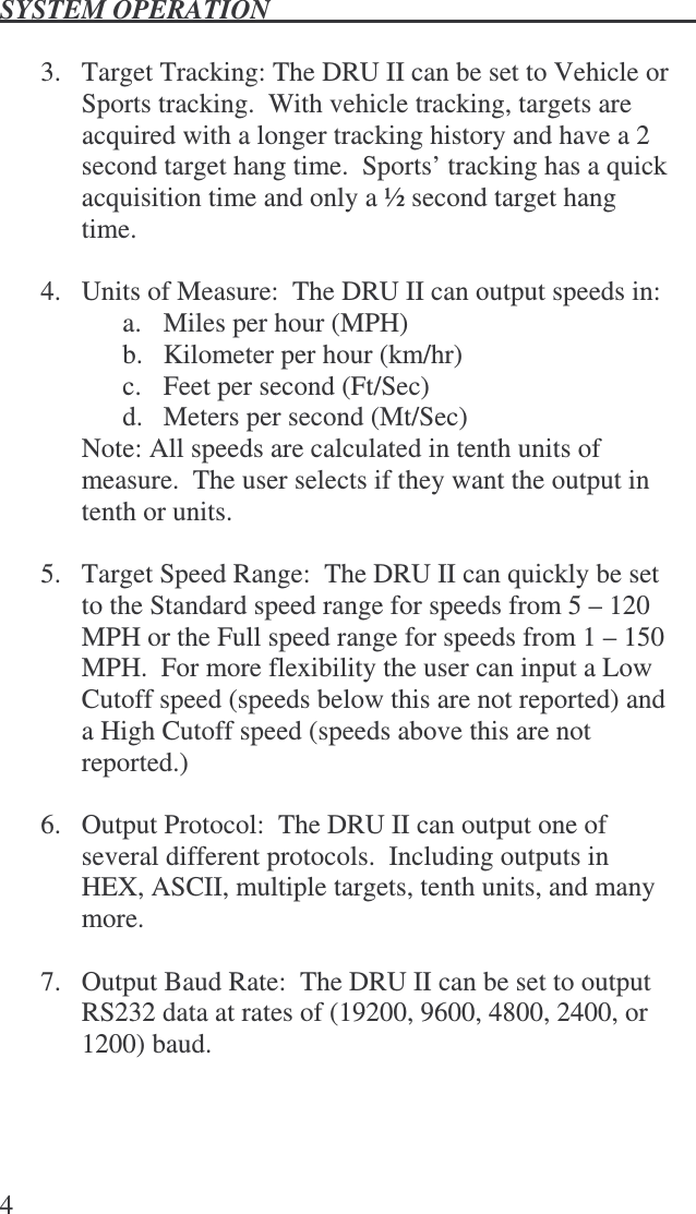
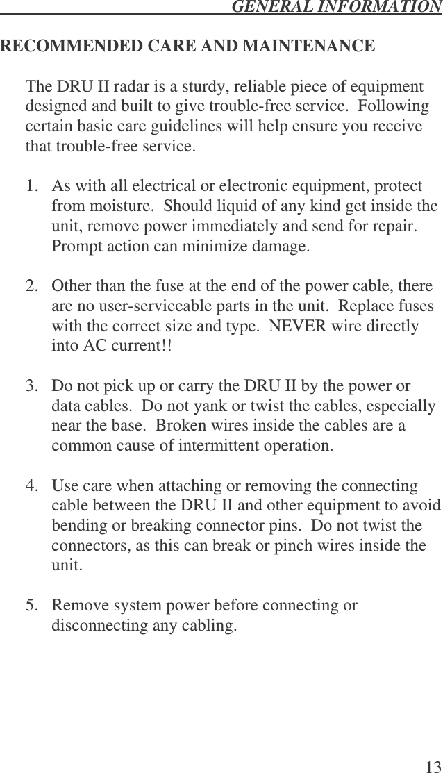
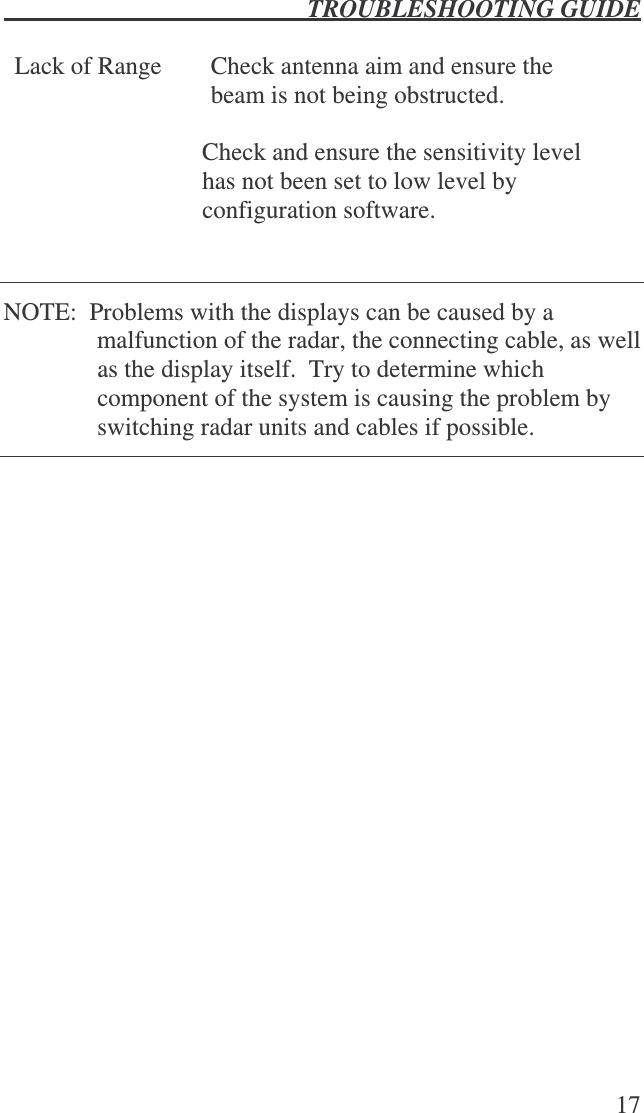
![SYSTEM OPERATION 5 8. Output Update Rate: The DRU II can be set to output packets of speed data at rates of (8 times per second, 4 times a second, 2 times a second, once a second, upon speed change, or when the user’s equipment polls for data) Note: If Output Update Rate is set to upon speed change, the DRU II outputs speeds immediately when the speeds changes by at least one unit or once every two seconds if the speed is not changing. If the DRU II is set to the Polled output, data is output when the DRU II receives characters [“*P”] or [“*P”0x0D]. Once all the selections have been made, click the Send Setting button to send the configuration data to the DRU II.](https://usermanual.wiki/Kustom-Signals/DRU-II/User-Guide-668755-Page-11.png)