Kustom Signals DRU-II FIELD DISTURBANCE SENSOR User Manual DRUII Operator s Manual
Kustom Signals Inc FIELD DISTURBANCE SENSOR DRUII Operator s Manual
USERS MANUAL

OPERATOR’S MANUAL
P/N 006-0857-00
REV. 0
Copyright 2006
Kustom Signals, Inc.
All rights reserved
Printed in the United States of America
This publication may not be reproduced, stored in a retrieval
system or transmitted in whole or in part in any form or by
any means electronic, mechanical, photocopying, recording,
or otherwise without prior written permission of Kustom
Signals, Inc., 9325 Pflumm, Lenexa, Kansas 66215-3347.

TABLE OF CONTENTS
INTRODUCTION .....................................................................1
SYSTEM OPERATION
Radar Side View ...............................................................2
Configuration Options ......................................................3
Installation.........................................................................6
Monitoring Target Speeds.................................................6
Tuning Fork Test...............................................................7
GENERAL INFORMATION
Theory of Operation..........................................................9
Serial Port Output ...........................................................11
LED Indicator .................................................................11
Interference .....................................................................12
Recommended Care & Maintenance ..............................13
KSI Radar Microwave Emission ....................................14
TROUBLESHOOTING GUIDE
Troubleshooting .............................................................16
TECHNICAL SPECIFICATIONS
Microwave ......................................................................18
General............................................................................18
REFERENCES
FCC Rules.......................................................................19
WARRANTY ..........................................................................21

INTRODUCTION
1
INTRODUCTION
This Directional Radar Unit, known as DRU II, is
designed and built for target speed sensing applications.
The DRU II has been completely redesigned for
flexibility, simple operation, small size and extremely
low current consumption. The DRU II is intended for
uses in traffic, industrial, and sports products. Examples
of these applications are the Kustom Signals S.M.A.R.T.
series trailers, Pole Mounted Speed Displays and
StealthStat statistics gathering systems.
The DRU II is designed to be an extremely flexible unit.
Kustom Signals provides PC software to allow the user to
setup the DRU II to operate in many different
configurations.
The radar itself is incredibly simple to operate--just
connect it to a compatible display or PC, and power it up.
The DRU II will output RS232 speed data in the selected
output protocol as long as the unit is powered.
With a size of only 3.5”x 3”x 2.25” the DRU II is a
complete one-piece unit, that can easily be mount to the
user’s equipment.
The DRU II sets a new standard for low current
consumption. This dramatically improves run times in
battery-operated applications.
Although the DRU has no frills outside, it has Kustom
Signals' uncompromising quality inside to give you years
of trouble-free, accurate, reliable, speed measurements.
SYSTEM OPERATION
2
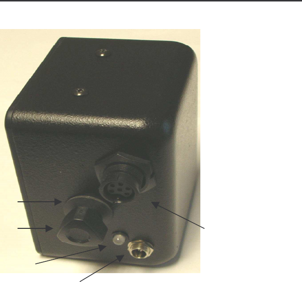
RADAR SIDE VIEW
A
B F
C
D
A. RUBBER WASHER: Rests on mounting screw between
mounting bracket and radar unit.
B. MOUNTING BRACKET SCREW: Connects bracket to
radar unit.
C. INDICATOR LED: Strongest target direction indicator.
D. POWER CONNECTOR: Provides screw down
connection to the provided power cable
E. DATA CONNECTOR: Connections for bi-directional
RS232 serial data cable.
SYSTEM OPERATION
3
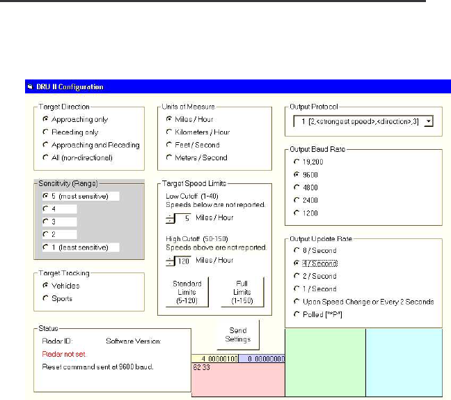
CONFIGURATION OPTIONS
The DRU II was designed to give the user a configurable
radar unit that can be setup for their needs. A simple PC
program let the user select:
1. Target Direction: The DRU II can output speeds for
targets traveling in the direction of:
a. Approaching Only
b. Receding Only
c. Approaching and Receding
d. Non Directional (all targets output)
2. Sensitivity (Range): The DRU II can be set for
sensitivity from 5 (most sensitive) to 1 (least
sensitive).

SYSTEM OPERATION
4
3. Target Tracking: The DRU II can be set to Vehicle or
Sports tracking. With vehicle tracking, targets are
acquired with a longer tracking history and have a 2
second target hang time. Sports’ tracking has a quick
acquisition time and only a ½ second target hang
time.
4. Units of Measure: The DRU II can output speeds in:
a. Miles per hour (MPH)
b. Kilometer per hour (km/hr)
c. Feet per second (Ft/Sec)
d. Meters per second (Mt/Sec)
Note: All speeds are calculated in tenth units of
measure. The user selects if they want the output in
tenth or units.
5. Target Speed Range: The DRU II can quickly be set
to the Standard speed range for speeds from 5 – 120
MPH or the Full speed range for speeds from 1 – 150
MPH. For more flexibility the user can input a Low
Cutoff speed (speeds below this are not reported) and
a High Cutoff speed (speeds above this are not
reported.)
6. Output Protocol: The DRU II can output one of
several different protocols. Including outputs in
HEX, ASCII, multiple targets, tenth units, and many
more.
7. Output Baud Rate: The DRU II can be set to output
RS232 data at rates of (19200, 9600, 4800, 2400, or
1200) baud.

SYSTEM OPERATION
5
8. Output Update Rate: The DRU II can be set to output
packets of speed data at rates of (8 times per second,
4 times a second, 2 times a second, once a second,
upon speed change, or when the user’s equipment
polls for data)
Note: If Output Update Rate is set to upon speed
change, the DRU II outputs speeds immediately when
the speeds changes by at least one unit or once every
two seconds if the speed is not changing.
If the DRU II is set to the Polled output, data is output
when the DRU II receives characters [“*P”] or
[“*P”0x0D].
Once all the selections have been made, click the Send
Setting button to send the configuration data to the DRU II.

SYSTEM OPERATION
6
INSTALLATION
Install the DRU II unit into your system as follows:
1. Mount the radar in its bracket.
2. Attach one end of the data cable to the 6-pin data
connector on the side of the DRU II. Ensure the
connection is firm and tighten the connector’s locking
ring.
3. Plug the other end of the cable to the compatible
display or PC.
4. Connect the power cable to the power connector on the
side of the DRU II.
5. Connect the power cable to 8 – 16.5VDC source.
MONITORING TARGET SPEEDS
Aim the radar carefully, as nearly as possible directly in
the target path.
Once the radar has been properly set up and powered it is
ready for use. Acquiring and displaying valid target
speeds requires proper antenna aiming.
Be alert to terrain or roadside features, which can cause
interference, incorrect readings, or display blanking.
(Such features include power lines, radio/TV transmitters,
bridges, guardrails, signs, buildings and other large
reflectors, etc.)

SYSTEM OPERATION
7
TUNING FORK TEST
The DRU II unit can be configured to output speeds of
targets that are approaching only, receding only, both
approaching and receding, or all targets including non-
directional targets. Tuning forks can only be reliably
read in the all targets mode. (Tuning fork signals are
generally non-directional targets).
NOTE: Some display systems only display non-
directional target for a short time after power up.
A 35 MPH (or 45 KPH) tuning fork is supplied with the
radar. Strike the tuning fork on a hard, non-metallic
surface. Hold the vibrating tuning fork approximately one
inch in front of the antenna. The output speed should
register "35" ("45"). Please note--readings of ±1 MPH
(KPH) are considered acceptable.
If the proper reading is not obtained:
1. Make sure that Kustom Signals K-Band tuning forks
have been used ("K-Band" is stamped plainly on each
fork). A different band tuning fork, or tuning forks
designed for other manufacturers' radar, will not give the
proper readings.
2. Striking the tuning forks too hard may produce false
overtones, which may be read as speeds above or below
those specified. These possible false readings are
momentary, and the proper readings should appear as
the false overtones dissipate. Do not move the tuning
forks after placing them in front of the antenna.

SYSTEM OPERATION
8
3. Extremely cold or extremely hot tuning forks may give
readings slightly above or below those specified, due to
the effect of extreme temperature on the metal. If this
is the case, warm or cool the forks to normal room
temperature before use.
GENERAL INFORMATION
9
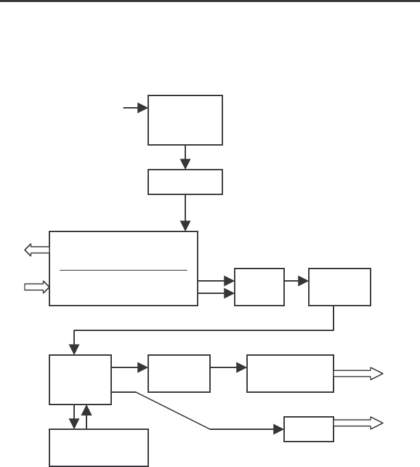
THEORY OF OPERATION
Block Diagram:
+12VDC Input
The Directional Radar Unit (DRU II) transmits a radio
frequency of 24.125 Gigahertz, in accordance with
Federal Communications Commission regulations. When
the transmitted signal strikes a moving target, it returns at
a different frequency because there is relative motion
between the two objects (radar unit and target). Targets
approaching the radar will return an echo higher than the
transmitted frequency. Targets receding from the radar
will return an echo lower than the transmitted.
K-Band 20dB(EIRP)
Transceiver Module
Mixers / Preamplifier
Power
Supply
5
VDC
PGA
A/D
Flash
DSP RS232
Serial Port
EE Memory
LED

GENERAL INFORMATION
10
This returning signal is mixed with the transmitted signal
in a balanced I/Q demodulator mixer. The difference in
frequency (Doppler frequency) is proportional to the
speed of the target; the difference in phase is related to
the direction of target travel. These returned echo signals
are a very low level. Preamplifiers and Programmable
Gain Amplifiers increase the signal level.
The signals are then converted from analog to digital by
the A/D converter. This digital signal stream is feed to
the Digital Signal Processor (DSP). The DSP transforms
the data to the frequency domain, where the data is
analyzed and processed to find valid moving targets.
To become a valid target the signals must meet the
criteria setup by the user for target directionality and
speed limitations. The DSP will convert the speed of the
valid targets into the unit of measure set by the user and
output the RS232 data via the serial port.

GENERAL INFORMATION
11
SERIAL PORT OUTPUT
The user configures the format serial target data that
comes out the serial port. There are several different
protocol formats and baud rates to choose from. The pin
out for the serial connector is as follows:
1. RS232 data out of the DRU II
2. Ground
3. Doppler Q analog signal
4. Hold Control
5. Doppler I analog signal
6. RS232 data in to the DRU II
LED INDICATOR
The DRU II has a bicolor LED to indicate the status of
the current strongest valid target. The statuses the LED
can indicate are as follows:
1. Short burst of flashing red = DRU II is running, no
valid target present.
2. Red flashing at 50% duty cycle = strongest target is
not moving.
3. Solid Red = strongest target is receding.
4. Solid Green = strongest target is approaching.

GENERAL INFORMATION
12
INTERFERENCE
Interference from any external event can influence the
operation of the radar. These influences can be natural or
man-made. A knowledgeable operator will not be
confused by these external influences.
Natural events such as driving rain or blowing dust can
cause a scattering effect, or diffusion, which can decrease
the effective range of the radar. Terrain can also affect
the radar's range. Should the device be on a slight
decline, the antenna could be shooting short of the target.
If on a slight incline, it could be shooting over the target.
Range will be decreased in either case.
Man-made influences are by far the most troublesome,
because they generally involve electronic signals, which
may cause spurious displays. Power transformers, radio
transmitters, fans, etc generate electronic noise signals.
If the power supply voltage to the DRU II unit drops below
the level required for proper operation, power to the
microwave transmitter will be turned off. This prevents
false readings from occurring during periods of low
voltage.

GENERAL INFORMATION
13
RECOMMENDED CARE AND MAINTENANCE
The DRU II radar is a sturdy, reliable piece of equipment
designed and built to give trouble-free service. Following
certain basic care guidelines will help ensure you receive
that trouble-free service.
1. As with all electrical or electronic equipment, protect
from moisture. Should liquid of any kind get inside the
unit, remove power immediately and send for repair.
Prompt action can minimize damage.
2. Other than the fuse at the end of the power cable, there
are no user-serviceable parts in the unit. Replace fuses
with the correct size and type. NEVER wire directly
into AC current!!
3. Do not pick up or carry the DRU II by the power or
data cables. Do not yank or twist the cables, especially
near the base. Broken wires inside the cables are a
common cause of intermittent operation.
4. Use care when attaching or removing the connecting
cable between the DRU II and other equipment to avoid
bending or breaking connector pins. Do not twist the
connectors, as this can break or pinch wires inside the
unit.
5. Remove system power before connecting or
disconnecting any cabling.

GENERAL INFORMATION
14
KSI RADAR MICROWAVE EMISSION
A traffic radar operator may justifiably have some concerns
about the biological effects of exposure to the microwave
energy produced by the radar device. According to all
credible evidence, the emission levels resulting from traffic
radar use pose no threat whatsoever, either to the radar
operator or to target vehicle occupants.
One widely recognized authority for safe limits of
nonionizing radiation exposure is the American National
Standards Institute, which recommends a maximum power
density of 10.0 mW/cm
2
for the frequency bands on which
Kustom Signals traffic radar systems operate (ANSI C95.1-
1994, "American National Standards Safety Levels with
Respect to Human Exposure to Radio Frequency
Electromagnetic Fields, 300 KHz to 100 GHz").
The Center for Devices and Radiological Health, an agency
of the U.S. Food and Drug Administration, recommends
similar limits (Title 21 Code of Federal Regulation,
Subchapter J, Section 1030.10, "Performance Standards for
Microwave and Radio Frequency Emitting Products"). The
10.0 mW/cm
2
limit is clearly accepted by most reputable
scientific and medical authorities.

GENERAL INFORMATION
15
All Kustom Signals’ radar systems utilize microwave
oscillators, which produce aperture power densities,
measured directly at the face of the antenna, in the range of
approximately 0.3 to 2.3 mW/cm
2
. The vast majority of
units produce values in the 0.3 to 0.6 mW/cm
2
range.
Under no circumstances would a Kustom Signals traffic
radar unit be capable of producing an aperture power
density in excess of 4.0 mW/cm2, still well below the safe
limit. Bear in mind that these are level measurements taken
directly in the main beam of the antenna, and that the
power densities produced at the sides and rear of the unit
are typically at least one hundred times lower than in the
main beam.
Another reference document on this topic is a DOT
publication entitled "Field Strength Measurements of Speed
Measuring Radar Units" (NHTSA Technical Report #DOT-
HS-805 9 8). This report documents a series of tests
performed by the National Bureau of Standards on twenty-
two commonly used traffic radar units. Aperture power
density levels measured were from 0.25 to 2.82 mW/cm
2
,
while back-lobe power density values ranged from 0.001 to
0.02 mW/cm
2
. These measurements were obtained with
the radars mounted inside vehicles, as in normal operating
conditions.
While traffic radar devices do emit microwave radiation,
the levels are so low that there are no possible harmful
effects. You may use your Kustom Signals radar unit with
complete confidence in its safety, as well as in its accuracy.

TROUBLESHOOTING GUIDE
16
TROUBLESHOOTING
If you are having operating difficulty, recheck the
operating information in this manual, then check the
following before notifying your Kustom Signals
representative of a problem.
Problem Possible Solution
No indications
on LED. Check fuse. For access to fuse, remove
tip of power plug by turning counter-
clockwise. NOTE: Replace radar fuse
with ONLY 2A Fast-Blow.
Ensure power cable is firmly attached.
Check for dirty power receptacle or
dead battery.
No target
indication on
LED, no speed
readings
RS232
Check antenna aim; ensure beam is
not being obstructed.
No speed-
readings
RS232, LED
indicating
targets.
Check data cable connections.
Intermittent
speed readings
Often caused by interference from stray
noise (Fans, electrical equipment, RFI).

TROUBLESHOOTING GUIDE
17
Lack of Range
Check antenna aim and ensure the
beam is not being obstructed.
Check and ensure the sensitivity level
has not been set to low level by
configuration software.
NOTE: Problems with the displays can be caused by a
malfunction of the radar, the connecting cable, as well
as the display itself. Try to determine which
component of the system is causing the problem by
switching radar units and cables if possible.

TECHNICAL SPECIFICATIONS
18
MICROWAVE
Frequency: 24.125 + .1 Ghz (K-Band)
Output Power (EIRP):
20dBm
Source: PHEMT or DRO
Antenna Type: Planar Array
Polarization: Linear
Horizontal
Beamwidth: 12
o
Receiver Type: Dual Channel low noise
GENERAL
Supply Voltage
Range:
7.4 - 24.0 VDC
12.6 VDC (nominal)
Supply Current
< 100ma. @12.6 VDC
Environmental:
-30
o
C to +65
o
C; 90% relative
humidity at +37
o
C, noncondensing
Target Speed Range:
User selectable from 1 – 150
MPH.
Size:
3.5”H x 3.0”W x 2.3”D
Accuracy:
+ 1 MPH or KPH

REFERENCES
19
FEDERAL COMMUNICATIONS COMMISSION:
TRANSMITTER RULES AMENDED
The Commission has amended its rules to eliminate the
required annual measurement of transmitter power,
frequency and modulation, and to specify transmitter
power in terms of output power for licensees in the Public
Safety, Industrial, and Land Transportation Radio
Services.
The action was the result of a rulemaking procedure
initiated October 29, 1976 on request of HT & B
Electronics.
Under the rules, which amend Parts 89, 91, and 93,
licensees will continue to be required to operate their
transmitters within the specified technical parameters.
For the sake of convenience and simplicity of transmitter
power measurement, the FCC specified that in the future,
transmitter output power, rather than the direct current
input power to the final radio frequency stage, be the
standard parameter used to indicate transmitter power.
The FCC defined transmitter output power as that power
measured at the transmitter output terminals when
connected to a load of the impedance recommended by
the equipment manufacturer.

REFERENCES
20
FEDERAL COMMUNICATIONS COMMISSION;
RADAR UNIT LICENSING AMENDED (PART 90)
The Commission has eliminated a requirement for local
governmental entities licensed in the Public Safety Radio
Services to obtain a separate authorization for radar speed
detection devices.
This change will reduce paperwork for the Commission's
licensing staff and for police and other local government
units, which will no longer have to apply for new radar
authorizations or modify or renew existing licenses and
may operate speed detection devices as part of their
base/mobile communications systems.
To provide the Commission with a record of such units in
use, licensees will be required to list the number of speed
detection units and the frequencies on which they operate
at the time of renewal of their land mobile authorizations.
Ordinarily, this would be once every five years and
would not be a significant addition to the renewal
process, the Commission noted.
This action became effective February 1, 1983.

WARRANTY
21
The Kustom Signals Traffic Safety Radar system is
guaranteed to be free of defects in materials and
workmanship for a period of two (2) years from date of
delivery to the Owner or Lessee.
•
This Warranty applies only to the original registered
Owner or Lessee on file at Kustom Signals, Inc., and
cannot be assigned or transferred to a third party.
•
The Owner or Lessee shall use the Equipment in
accordance with the manufacturer’s operational
instructions.
•
The Owner’s or Lessee’s exclusive remedy under this
Warranty is limited to repair to the manufacturer’s
operational specifications or replacement, at the sole
discretion of Kustom Signals, Inc. or its agent, of the
Equipment as (i) is covered by this Warranty; (ii) is
delivered to Kustom Signals, Inc. or its agent at the
Owner’s or Lessee’s expense within the term of this
Warranty; and (iii) upon examination thereof discloses
to the exclusive satisfaction of Kustom Signals, Inc. or
its agent to have been defective in material or
workmanship. Warranty service and repairs must be
performed by an Authorized Kustom Signals Warranty
Service Center or the Factory Customer Service Center
or this Warranty is void.
•
Failure of the Owner or Lessee to observe any
conditions set forth in this warranty; or equipment
damage arising from flood, fire, vehicle collision, act of
God or similar event or catastrophe; or tampering,
abuse, or misuse of the equipment by Owner, Lessee or
third party will render the Owner or Lessee responsible
for the cost of bringing the system within the
manufacturer’s operational specifications.

WARRANTY
22
•
This warranty is not intended to supplant normal care
and service by the Owner or Lessee, as specified in the
Operator’s Manual, and shall not apply to Equipment
which has been defaced or damaged through normal
usage.
•
The liability of Kustom Signals, Inc., if any, with
respect to the equipment, shall be limited as provided in
this Warranty. Kustom Signals, Inc. disclaims any
obligation or liability for the loss of use of the
Equipment warranted, loss of time, inconvenience,
commercial loss or other direct, consequential, special
or incidental damages. Kustom Signals, Inc. makes no
warranties of any kind other than as herein expressly
provided, expressed or implied, and specifically
disclaims the implied warranties of merchantability and
of fitness for a particular purpose. You may have
additional rights under this Warranty that vary from
state to state.
•
No action for breach of this warranty may be
commenced more than one year after the date of alleged
breach.
EQUIPMENT SUPPLIED WITH CONSUMABLE
ITEMS
Items such as tires, non-rechargeable batteries, light bulbs,
transmitter carrying pouch, and microphone cables
w/microphone and windscreen are considered consumable
items and as such are not covered by this warranty.
SMART RADAR
SMART system radar units are warranted for two years,
subject to the warranty terms listed above.
9/2003