Kustom Signals FAL-HR FIELD DISTURBANCE SENSOR User Manual 006 0862 00 1a
Kustom Signals Inc FIELD DISTURBANCE SENSOR 006 0862 00 1a
UserManual.wiki
>
Kustom Signals
>
FAL HR User Manual
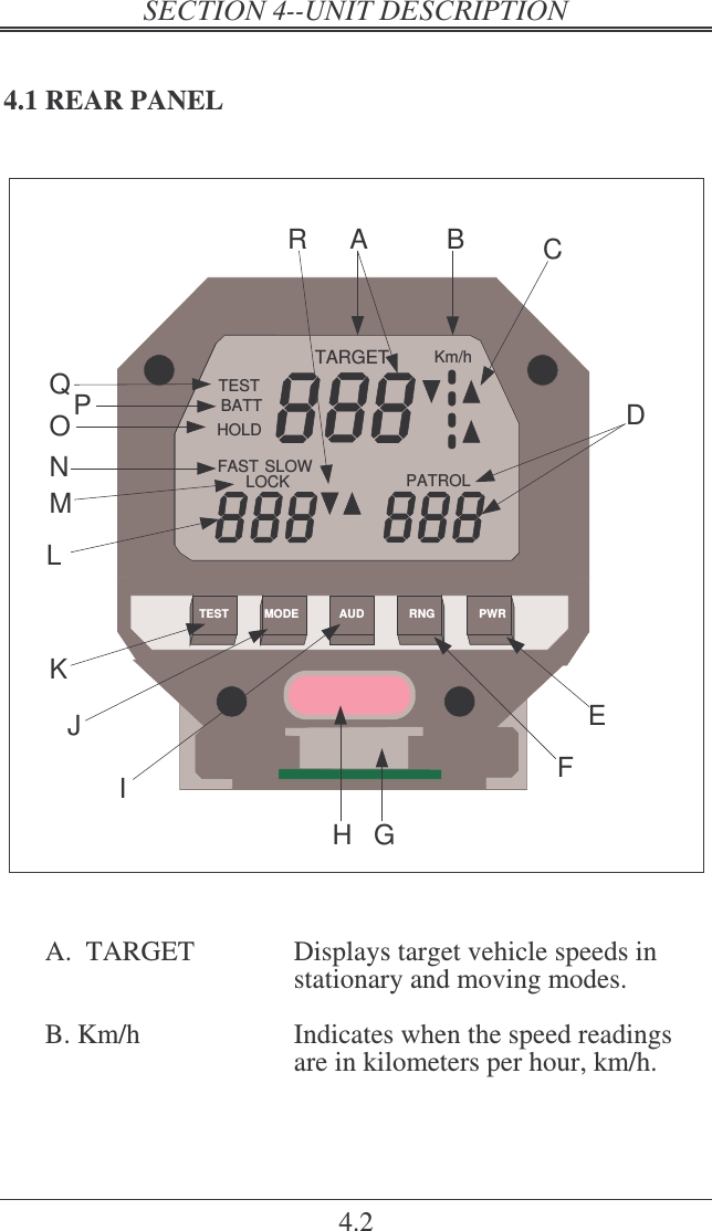
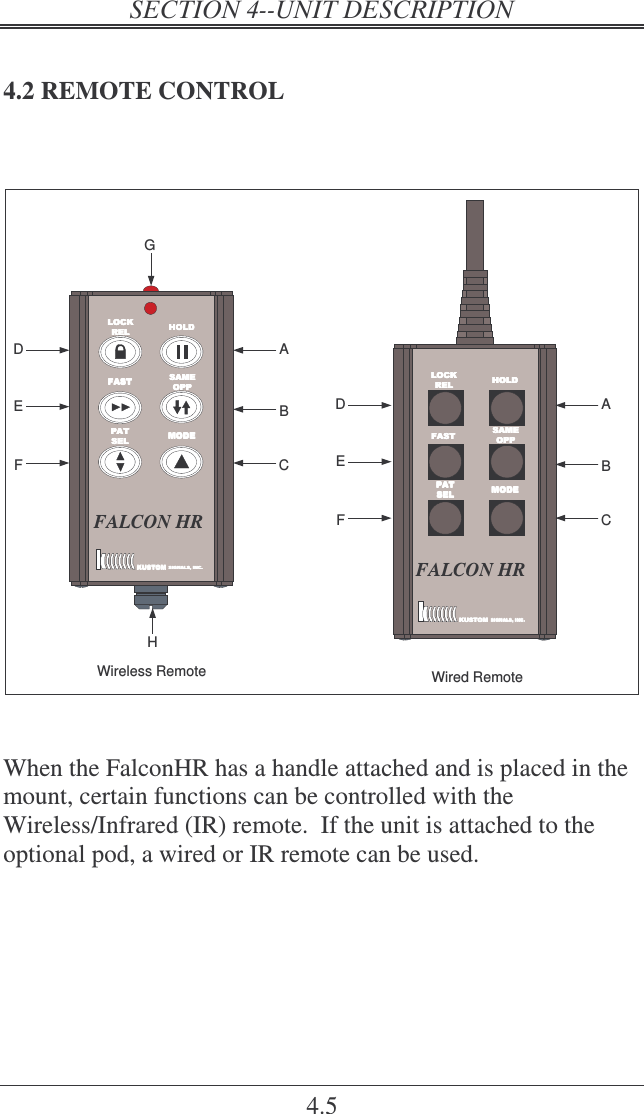
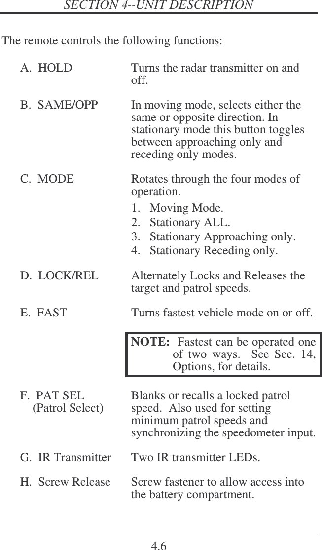
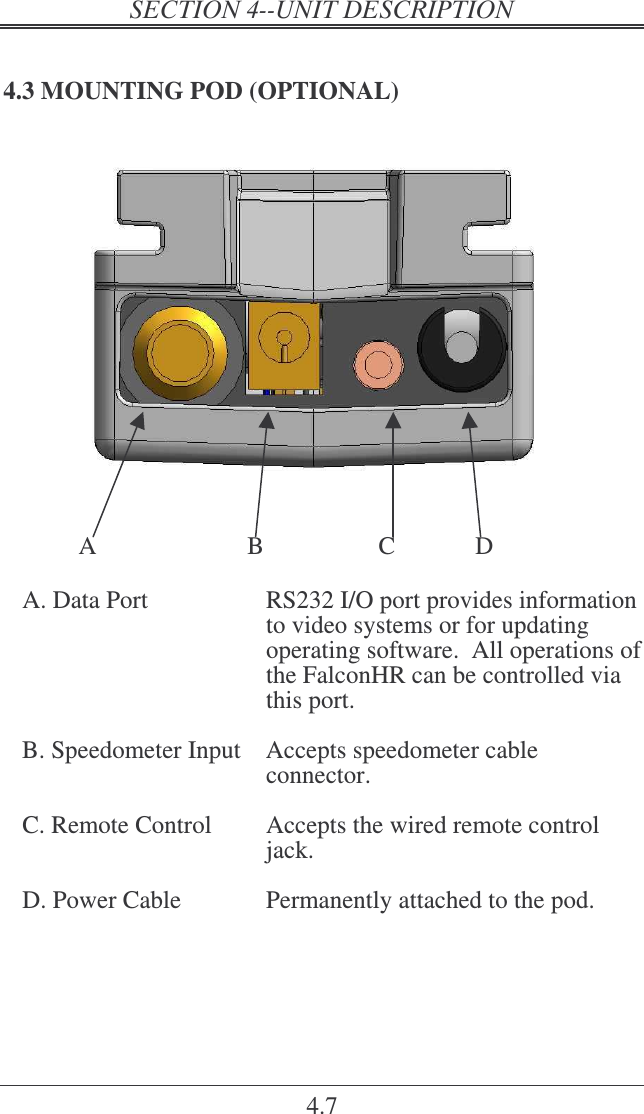
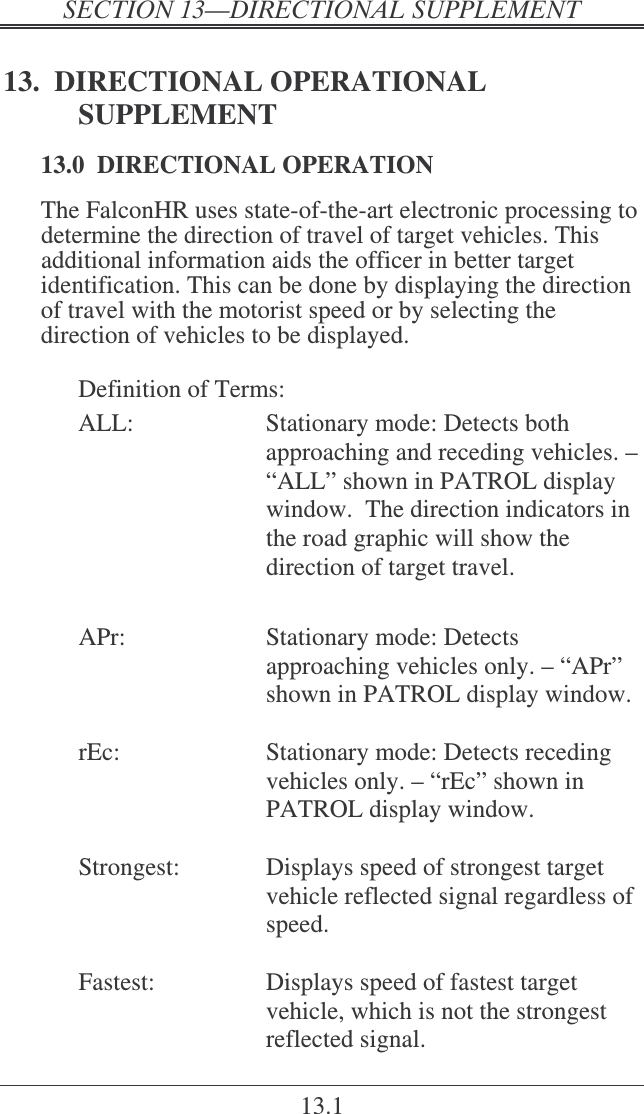
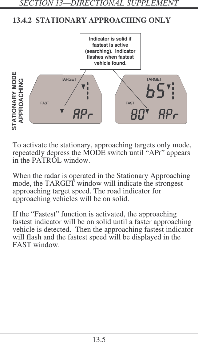
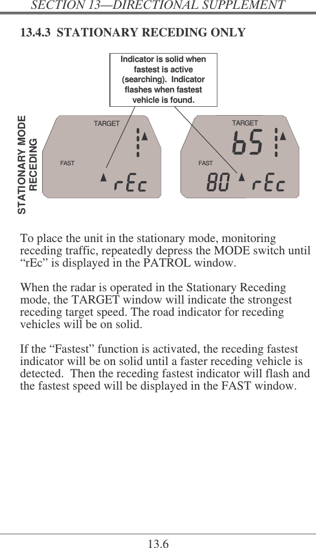
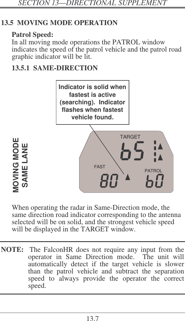
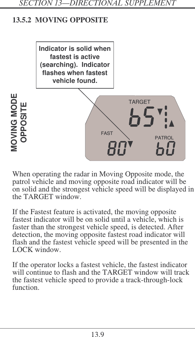
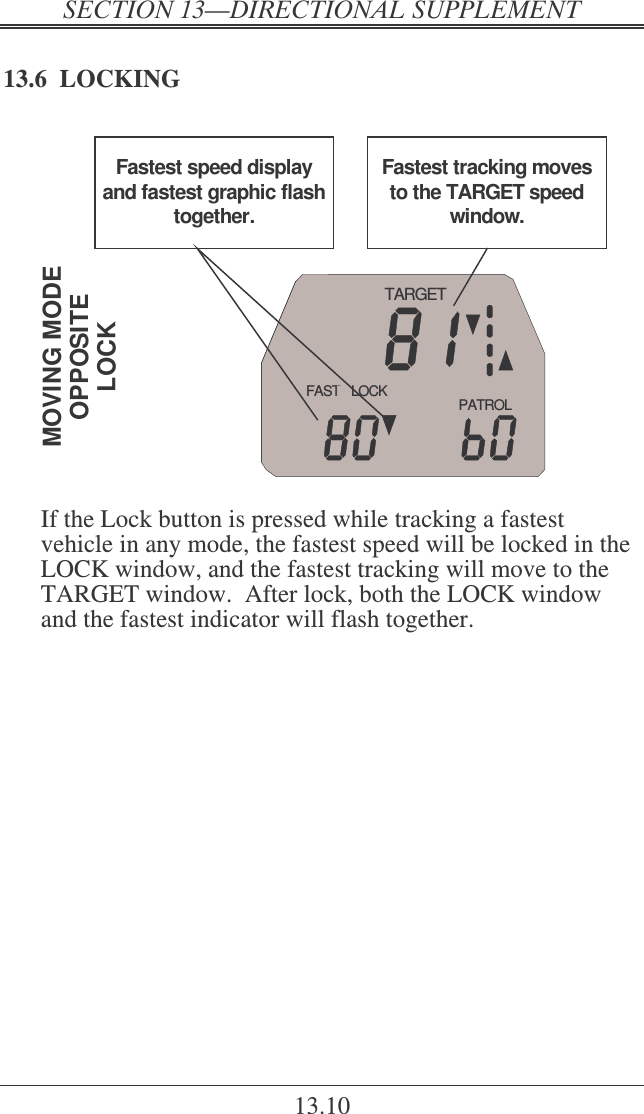
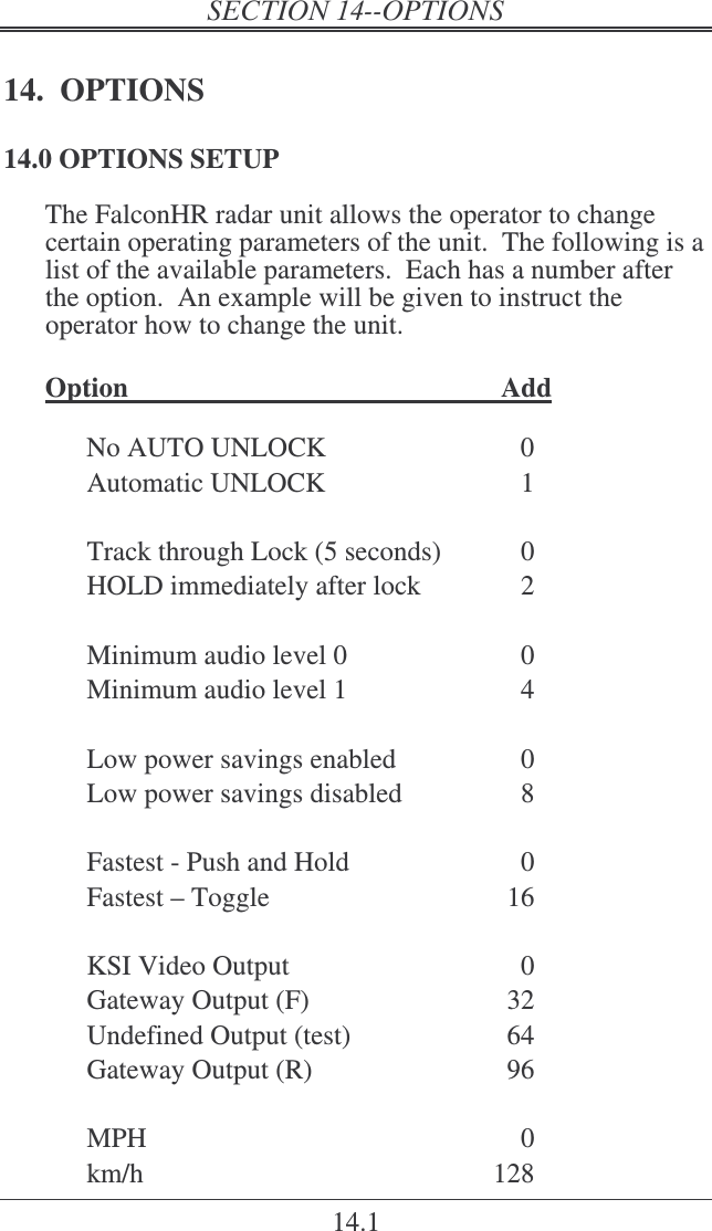
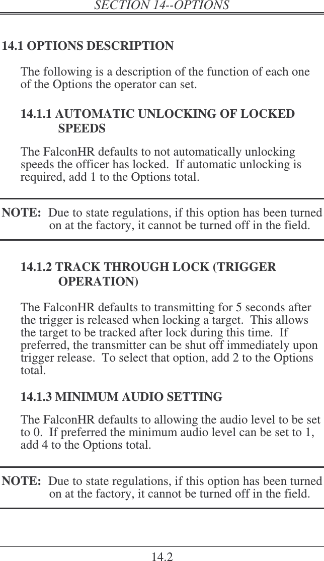
USERS MANUAL
Navigation menu
Upload a User Manual
Namespaces
Wiki Guide
HTML
PDF
Info
Views
User Manual
Discussion / Help
Navigation