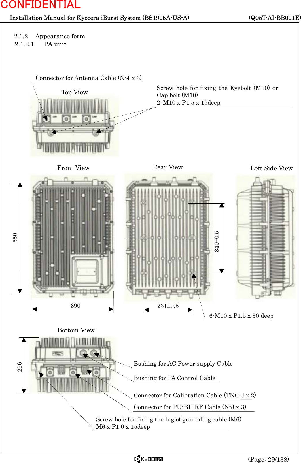
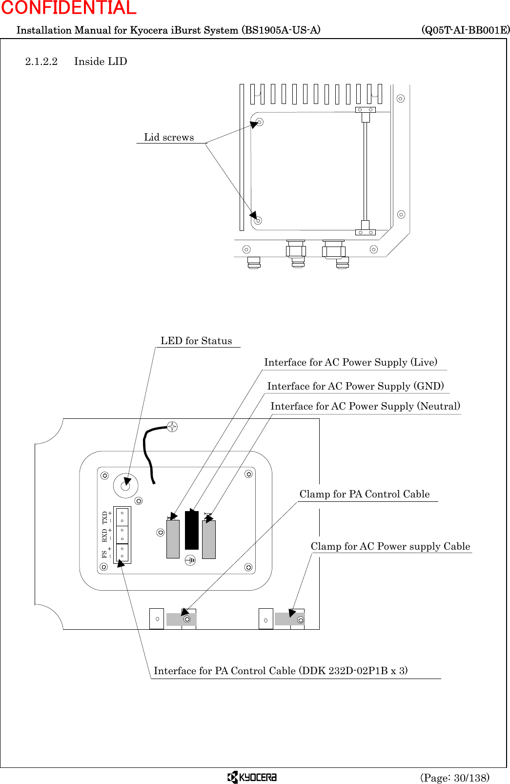
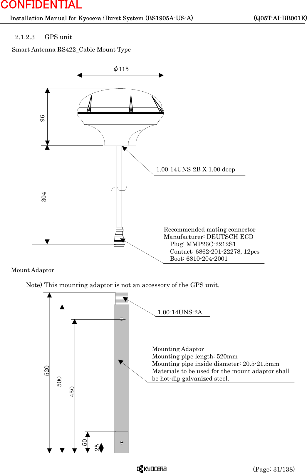
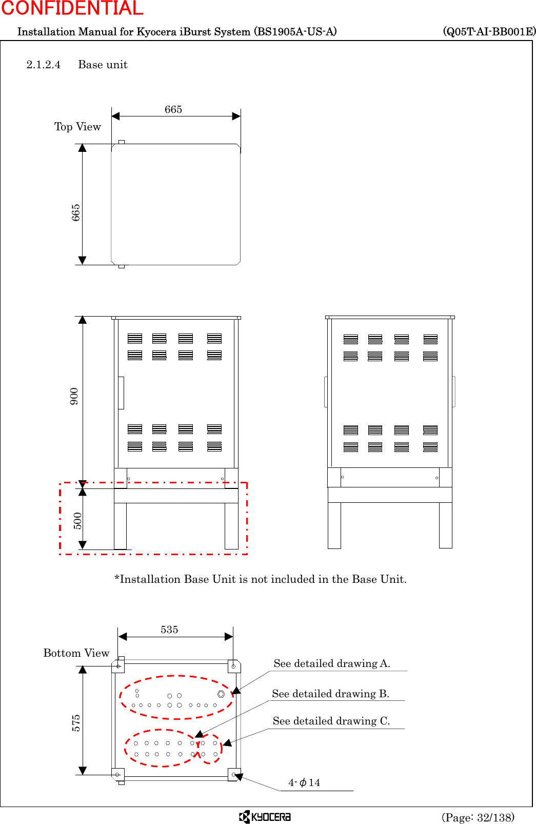
Kyocera IBS19AA Base Station of Wireless Broadband Internet System User Manual

Kyocera Corporation Base Station of Wireless Broadband Internet System

User Manual

 Installation Manual for Kyocera iBurst System (BS1905A-US-A)     (Q05T-AI-BB001E) (Page: 1/138) CONFIDENTIAL                April 26, 2004 Revision 1.00  Doc-No. Q05T-AI-BB001E     Kyocera Corp. 2-1-1 Kagahara, Tsuzuki-ku, Yokohama-city, Kanagawa 224-8502, Japan       Telephone:+81-45-943-6176 Fax:+81-45-943-6123  © KYOCERA Corporation 2003 All right reserved.  No part of this publication may be excerpted, reproduced,   translated or edited, in any form by any means, without   the prior written permission of KYOCERA Corporation      Installation Manual for Kyocera iBurst System (BS1905A-US-A) Approved  Checked Checked Prepared
 Installation Manual for Kyocera iBurst System (BS1905A-US-A)     (Q05T-AI-BB001E) (Page: 2/138) CONFIDENTIAL  Revision History  Revision Description  Date Charge 1.00 1st Edition  April 26, 2004  Y. Izawa                                                                    1. INSTALLATION CRITERIA...................................................................................................... 5 1.1 PURPOSE AND POLICY...........................................................................................................6 1.2 LAWS ....................................................................................................................................6 1.3 PRECAUTIONS FOR HANDLING..............................................................................................6 1.4 DESIGN AND EXECUTION POLICY ..........................................................................................6 1.5 INSTALLATION CRITERIA.......................................................................................................6 1.5.1 General.........................................................................................................................6 1.5.2 Criteria for selecting antenna location .......................................................................8 1.5.2.1 Accuracy of antenna mounting ............................................................................8 1.5.2.2 Sequence of mounting antenna............................................................................8 1.5.2.3 Interval of antenna...............................................................................................8 1.5.2.4 Lightening protection...........................................................................................9 1.5.2.5 Isolation from drain..............................................................................................9 1.5.2.6 Isolation from obstacle .......................................................................................10 1.5.2.7 Horizontal sight angle........................................................................................10 1.5.2.8 Vertical sight angle............................................................................................. 11 1.5.2.9 Isolation from radio system................................................................................12 1.5.2.10  Isolation from outdoor unit of air conditioner, etc. ...........................................14 1.5.2.11 Isolation from power line ...................................................................................14 1.5.3 Criteria for selecting PA unit location ......................................................................15 1.5.3.1 Mounting direction of PA unit............................................................................15 1.5.3.2 Securing space for PA unit .................................................................................15 1.5.3.3 Lightening protection.........................................................................................16 1.5.3.4 Isolation from drain............................................................................................17 1.5.4 Criteria for selecting GPS unit location ...................................................................17 1.5.4.1 Accuracy of GPS mounting.................................................................................17 1.5.4.2 GPS sight space ..................................................................................................18 1.5.4.3 Lightening protection for GPS...........................................................................19 1.5.5 Criteria for selecting Base unit location...................................................................20 1.5.5.1 Installation space for Base unit.........................................................................20 1.5.5.2 Lightening protection for Base unit...................................................................20 1.5.5.3 Isolation from drain............................................................................................21 1.5.5.4 Isolation from iBurst antenna ...........................................................................21 1.5.6 Precautions on cabling ..............................................................................................22 1.5.6.1 Ground ................................................................................................................22 1.5.6.2  Cable ................................................................................................................... 22 1.5.7 Precautions in installation on the roof .....................................................................23
 Installation Manual for Kyocera iBurst System (BS1905A-US-A)     (Q05T-AI-BB001E) (Page: 3/138) CONFIDENTIAL 1.5.8 Separation of power systems.....................................................................................24 1.5.9 Waterproof treatment for connector and bushing ....................................................25 2 CONFIGURATION OF BASE STATION AND ACCESSORIES.......................................... 26 2.1 CONFIGURATION OF BASE STATION....................................................................................27 2.1.1 System Diagram ........................................................................................................27 2.1.1.1 Star connection...................................................................................................27 2.1.1.2 Daisy-chain connection.......................................................................................28 2.1.2 Appearance form........................................................................................................29 2.1.2.1 PA unit ................................................................................................................29 2.1.2.2 Inside LID........................................................................................................... 30 2.1.2.3 GPS unit..............................................................................................................31 2.1.2.4 Base unit.............................................................................................................32 2.1.3 Connection diagram...................................................................................................37 2.1.3.1 PA unit - Antenna ...............................................................................................37 2.1.3.2 PA unit-Base unit ...............................................................................................38 2.1.3.3  Base unit – Other equipment.............................................................................42 2.1.4 Pin assignment of cables/connectors.........................................................................43 2.1.4.1 AC Power supply cable.......................................................................................43 2.1.4.2 PA control cable .................................................................................................. 43 2.1.4.3 Network cable..................................................................................................... 44 2.1.4.4 GPS cable ............................................................................................................44 2.1.4.5 GPI cable.............................................................................................................45 2.1.4.6 Master/Slave cable..............................................................................................45 2.2 SPECIFICATIONS .................................................................................................................46 2.2.1 Hardware specifications ............................................................................................46 2.2.2 LED indicators...........................................................................................................47 2.2.2.1 PA unit ................................................................................................................47 2.2.2.2 Base unit.............................................................................................................47 2.2.3 Accessories .................................................................................................................48 2.2.3.1 PA unit ................................................................................................................48 2.2.3.2 Base unit.............................................................................................................48 2.2.4 Cable specification.....................................................................................................48 2.2.5 Other Parts specification...........................................................................................49 2.2.6 Handling of cables .....................................................................................................50 2.2.7 Tightening Torque .....................................................................................................50 2.2.8 Tools............................................................................................................................51 3 INSTALLATION ................................................................................................................... 52 3.1 INSTALLING ANTENNA SYSTEM (EXAMPLE)........................................................................53 3.1.1 Installing the antenna pole .......................................................................................53 3.2 INSTALLING PA UNIT .........................................................................................................56 3.2.1 Mounting and removing the Eyebolt ........................................................................56 3.2.2 Mounting the PA Unit (Example) .............................................................................57 3.2.3 Connecting cables ......................................................................................................59 3.2.3.1 Connecting the AC power supply cable .............................................................59 3.2.3.2 Connecting the grounding cable. .......................................................................64 3.2.3.3 Connecting the PA control cable ........................................................................65 3.2.3.4 Connecting the antenna cable............................................................................70 3.2.3.5 Connecting the Calibration cable ......................................................................72 3.2.3.6 Connecting the PU-BU RF cable .......................................................................79 3.3 INSTALLING THE GPS UNIT ...............................................................................................82 3.4 INSTALLING THE BASE UNIT ..............................................................................................86 3.4.1 Mounting and removing the Eyebolt ........................................................................86 3.4.2 Fixing the Base Unit .................................................................................................88 3.4.3 Connecting cables ......................................................................................................89
 Installation Manual for Kyocera iBurst System (BS1905A-US-A)     (Q05T-AI-BB001E) (Page: 4/138) CONFIDENTIAL 3.4.3.1 Connecting the AC power supply cable .............................................................89 3.4.3.2 Fixing the grounding cable ................................................................................94 3.4.3.3 Connecting the PA control cable ........................................................................95 3.4.3.4 Connecting the GPS cable................................................................................100 3.4.3.5 Connecting the Calibration cable ....................................................................105 3.4.3.6 Connecting the PU-BU RF cable ..................................................................... 110 3.4.3.7 Connecting the Network cable......................................................................... 114 3.4.3.8 Connecting the Master/Slave cable .................................................................123 3.4.3.9 Attachment of Grounding Kit .......................................................................... 130 3.4.4 Inserting the board..................................................................................................130 3.4.4.1  Notes at setting Boards and Power supply .....................................................131 3.4.4.2 Inserting the Power supply.............................................................................. 133 3.4.4.3 Inserting the LoCal board................................................................................133 3.4.4.4 Inserting the MoNerd board ............................................................................134 3.4.4.5 Inserting the TRx board...................................................................................134 3.4.4.6 Inserting the FAN tray.....................................................................................134 3.4.4.7  Removing the Power supply and other boards................................................135 3.4.5 Connecting cables to the Power supply and boards ...............................................136 3.4.5.1 Power supply.....................................................................................................136 3.4.5.2 LoCal board.......................................................................................................137 3.4.5.3 MoNerd board...................................................................................................137 3.4.5.4 TRx the board ...................................................................................................138                * iBurst is the trademark of ArrayComm. * All the things in which a size does not have a unit display are mm units.
 Installation Manual for Kyocera iBurst System (BS1905A-US-A)     (Q05T-AI-BB001E) (Page: 5/138) CONFIDENTIAL            1. Installation Criteria
 Installation Manual for Kyocera iBurst System (BS1905A-US-A)     (Q05T-AI-BB001E) (Page: 6/138) CONFIDENTIAL  1.1  Purpose and policy This document is intended to specify a fundamental design criterion for the installation of iBurst base station, thus ensuring smooth work and providing the customer with appropriate services and establishing easy-to-maintain system.  1.2 Laws In executing the work, necessary related laws (Telecommunications Business Law, Wired Telecommunications Law, Radio Law, Building Standard Law, Electric Work Specialist Law, Fire Fighting Law, etc. in Japan), other related laws, and licensing conditions must be observed. In addition, application for permission based on the law must be conducted without delay.  1.3  Precautions for handling The iBurst system contains precision components; therefore, do not give any strong shock by falling or dropping. Strong shock may result in a failure or badly affect the lifetime or the product.  1.4  Design and execution policy 1.4.1 In designing the work, functionality, reliability, maintainability, economy, etc. must be fully taken into account.  1.4.2 Not only enhancement of safety mind but also security for the third party must always be kept in mind.  1.4.3 Be sure to make efforts to complete better work objective in accordance with technological sense.  1.4.4 Be sure to keep communication with the owner and residents of the building and the neighboring residents with due consideration not to cause a problem.  1.4.5 Be sure to make efforts to grasp the status of the work, to give an appropriate advice, and to fulfill a duty of reporting the status.  1.4.6 Be sure to prevent the work from generating a noise or vibration to maintain the living environment.  1.4.7 Be sure to dispose the waste materials caused from the work in accordance with the specified method regarding the method, place, etc. of disposal, thereby preventing the occurrence of accident to be caused by the waste material.  1.4.8 In conducting a negotiation or design, future expansion of equipment should be considered as much as possible.  1.5 Installation criteria 1.5.1 General 1.5.1.1 Select the location where general public is hard to access but maintenance is easy.  1.5.1.2 Antenna and mounting stud must be located at a place where dropping or other accident, if any, may not be harmful for the personnel and general public.  1.5.1.3 In designing a base station, the location shall be determined by the study of strength against load and work product.
 Installation Manual for Kyocera iBurst System (BS1905A-US-A)     (Q05T-AI-BB001E) (Page: 7/138) CONFIDENTIAL 1.5.1.4 Do not place antenna, base station, or other obstruction in front of advertising display such as neon sign and signboard.  1.5.1.5 When conducting the work, select the location of antenna, base station, UPS, wiring, piping, etc. in consultation with the owner while considering the appearance.  1.5.1.6 Before implementing the work, check the status of any broken or damaged portion of the building and facilities associated with the installation area of the base station together with the owner or the person from the control company.  1.5.1.7 Materials for mounting equipment 1.5.1.7.1 Quality-of-the-material specification used for the mount of outdoor installation etc. is considered as hot- dip galvanized. Moreover, quality-of-the-material specification of inside-of-a-house installation is made into the anti-rust material more than electric zinc plating material, and a bolt and a nut also apply to this. However, about the place of conditions, which are easy to generate, such as rust etc., it applies to outdoor specification.   However, a hot-dip galvanized steel or Dacrotized finishing is recommended for the bolt directly fixed on PA unit mounting bracket.  1.5.1.7.2 In the connection of various cables, use of cold-shrinkable tube as well as self-fusing tape is recommended as a method of waterproof treatment.  1.5.1.8 Study the shape of the building and the status of waterproof treatment on the roof not to cause any problem in the installation on the building.
 Installation Manual for Kyocera iBurst System (BS1905A-US-A)     (Q05T-AI-BB001E) (Page: 8/138) CONFIDENTIAL  1.5.2 Criteria for selecting antenna location  1.5.2.1  Accuracy of antenna mounting   Antenna shall basically be installed vertically within the range of ±2 degrees off the vertical line.  1.5.2.2  Sequence of mounting antenna Each PA unit to be connected with the antenna has antenna numbers (ANT1 to ANT3). The location of ANT1 is not specified specifically.  1.5.2.3  Interval of antenna Antennas shall be separated by more than 3λ from each other as shown below. An average interval of antenna shall be separated by more than 8λ.   Frequency Isolation (L) 1.9GHz  More than 50cm                                  Sequence of antenna mounting and interval of antennas ANT1 ANT2 ANT3 L L 3λ 3λ 3λ 3λ 3λ 3λ 3λ 3λ 3λ 3λ 3λ 3λ
 Installation Manual for Kyocera iBurst System (BS1905A-US-A)     (Q05T-AI-BB001E) (Page: 9/138) CONFIDENTIAL  1.5.2.4 Lightening protection Antenna installation shall be designed to be within the protection angle (* 60 degrees) of the lightening rod. * Lightening protection method is obeying the law by State regulations.                                                       Lightening protections for antenna - Lightening rod -             Lightening protection for antenna - Raised conductor -   1.5.2.5  Isolation from drain       When installing the antenna on the roof of a building, keep the isolation distance of more than 1 m to prevent the pedestal from blocking the drain of the roof.                                         Isolation distance from roof drain More than 1.5m  When using raised conductor Roof-drain More than 1m Not OK 60° Lightening rod More than 1.5m 60° OK
 Installation Manual for Kyocera iBurst System (BS1905A-US-A)     (Q05T-AI-BB001E) (Page: 10/138) CONFIDENTIAL  1.5.2.6  Isolation from obstacle When installing the antenna on the building, be sure that there is no object such as roof buildings or advertising display that may block the electric wave around the antenna.                                                                     Isolation from obstacle  1.5.2.7  Horizontal sight angle Horizontal sight angle shall be 330 degrees or more for the purpose of enlarging the area. In addition, there shall be no obstruction along the direction to be covered.  Definition of horizontal sight angle: Horizontal sight angle from the antenna shall be more than the standard value. (Angle added by the sight direction in the horizontal angle of 360 degrees around the antenna excluding the direction that cannot keep the sight due to obstruction on the roof: See below)                    Antenna location Obstacle L L>2m On the horizontal line of antenna center. Regarded as obstacle Plane view of roof Penthouseγ: Horizontal sight angle γ Horizontal sight angle
 Installation Manual for Kyocera iBurst System (BS1905A-US-A)     (Q05T-AI-BB001E) (Page: 11/138) CONFIDENTIAL  1.5.2.8  Vertical sight angle The standard value shown in the following table shall be secured for vertical sight angle.  Vertical sight angle standard values Tilt angle  Standard value 7dBi (20 degrees)  30 degrees 9dBi (10 degrees)  20 degrees 11dBi (5 degrees)  10 degrees 11dBi (0 degree)  5 degrees  Upon confirmation of the “distance from edge” of an object, be sure “distance from edge” is within the corresponding “allowable distance” in the following table.  Vertical sight angle vs. allowable distance  Applied height (m) Calculated value (m) 11dBi 0 degree 11dBi 5 degrees 9dBi 10 degrees 7dBi 20 degrees Allowable sight angle (degrees)     5  10 20 30   4 or more  4  45.7  22.7  11.0  6.9   Over 3.5 and below 4 3.5 40.0 19.8 9.6 6.1   Over 3 and below 3.5 3 34.3 17.0 8.2 5.2   Over 2.5 and below 3 2.5 28.6 14.2 6.9 4.3 Allowable distance Over 2 and below 2.5 2 22.9 11.3 5.5 3.5 (m)  Over 1.5 and below 2 1.5 17.1 8.5 4.1 2.6   Over 1 and below 1.5 1  11.4 5.7 2.7 1.7   Over 0.5 and below 1 0.5  5.7 2.8 1.4 0.9 tan5°=0.0874886, tan10°=0.1763269, tan20°=0.3639702, tan30°=0.5773502            Sight angle and allowable distance Sight angle Height from floor (* Applied height) Distance from edge (* Must be within allowable distance)
 Installation Manual for Kyocera iBurst System (BS1905A-US-A)     (Q05T-AI-BB001E) (Page: 12/138) CONFIDENTIAL  1.5.2.9  Isolation from radio system When installing a base station, it is necessary to keep enough space so as not to give damage to other existing base stations.  1.5.2.9.1 Isolation from iBurst system When installing the iBurst systems on the same plane of the roof, keep the specified isolation distance.                                        Interval between iBurst systems  1.5.2.9.2 Isolation from GSM/CDMA base station When installing the antennas in GSM/CDMA base station close together, sufficient survey must be conducted           - Do not installing the iBurst antenna to direction of radiation.                   - When installing the iBurst antenna to anti-direction of radiation, please make sure shown below parameter and new calculation of isolation distance will be required.             Radiation pattern of iBurst antenna            Used frequency Rang (Up-link/Down-link) of GSM/CDMA antenna            Output power rating of GSM/CDMA antenna            Characteristic of BPF of GSM/CDMA antenna            Radiation pattern of GSM/CDMA antenna                 Example of isolation distance from GSM/CDMA base station --Top View  (Note) When a base station is installed close to other base station, a failure may possibly be caused on or from the associated base station. Direction of radiation GSM /CDMA Antenna iBurst Antenna iBurst Antenna Do not install the iBurst antenna to direction of radiation.   More than 2m
 Installation Manual for Kyocera iBurst System (BS1905A-US-A)     (Q05T-AI-BB001E) (Page: 13/138) CONFIDENTIAL  1.5.2.9.3  Isolation from other radio system Regarding the existing antenna of other radio system such as TV antenna, effect on the associated antenna shall be fully taken into account at the time of installation.   As TV antenna has directivity, no base station shall be located in the direction of the antenna. There may be the possibility of having an effect even outside the range of directivity due to the effect of reflection depending on the environment around the location. Practically, as shown in the following figure, the base station must not be located within the range of existing antenna direction ±45° on the same roof.    More than 3 m distance (horizontal) shall be allowed from TV antenna and installation within the range of ±45 degrees from TV antenna direction shall be avoided.                                                                                   Isolation from TV antenna    Plane Installation of thistype is not permittedas the antenna arm isconsidered as a circle. Directivity of TV antenna 45° 45° 3m 3m 3m OK Not OK OK
 Installation Manual for Kyocera iBurst System (BS1905A-US-A)     (Q05T-AI-BB001E) (Page: 14/138) CONFIDENTIAL  1.5.2.10 Isolation from outdoor unit of air conditioner, etc. When installing an antenna, it is necessary to keep the antenna away from the rotating metal such as a heat-dissipating fan of the outdoor unit of air conditioner, ventilating fan, etc.   When there is any rotating metal on the same horizontal plane, it is necessary to keep the isolation of more than 1.5 m. If, however, this isolation cannot be secured, isolation of more than 0.5 m from the top and bottom edges of the antenna must be secured.                                                                                Isolation from outdoor unit    1.5.2.11  Isolation from power line Isolation from power line shall be executed by confirming the details in accordance with the related laws. As power producer includes electric power company and Train Company, pay full attention to the surrounding conditions.   More than 1.5m More than 0.5m More than 0.5m
 Installation Manual for Kyocera iBurst System (BS1905A-US-A)     (Q05T-AI-BB001E) (Page: 15/138) CONFIDENTIAL  1.5.3  Criteria for selecting PA unit location  1.5.3.1  Mounting direction of PA unit PA unit can be installed only vertically with the antenna connector up.              1.5.3.2  Securing space for PA unit  1.5.3.2.1 Workspace When installing on the roof or the like, keep approx. 1m as a maintenance space around the PA unit.               Workspace for PA unit  1.5.3.2.2 Ventilation space When installing the PA unit on the wall, allow a ventilation space of more than 15mm.              Example of ventilation space for PA unit Lid Bush 1m More than 15mm Pedestal
 Installation Manual for Kyocera iBurst System (BS1905A-US-A)     (Q05T-AI-BB001E) (Page: 16/138) CONFIDENTIAL  1.5.3.3 Lightening protection PA unit installation shall be designed to be within the protection angle (* 60 degrees) of the lightening rod. * Lightening protection method is obeying the law by State regulations.               Lightening protection for PA unit - Lightening rod-               Lightening protections for PA unit- Raised conductor -  More than 1.5m  When using raised conductor More than 1.5m Not OK 60° Lightening rod 60° OK
 Installation Manual for Kyocera iBurst System (BS1905A-US-A)     (Q05T-AI-BB001E) (Page: 17/138) CONFIDENTIAL  1.5.3.4  Isolation from drain When installing the PA unit on the roof of a building, keep the isolation distance of more than 1 m to prevent the pedestal from blocking the drain of the roof.                 Isolation from drain   1.5.4  Criteria for selecting GPS unit location  1.5.4.1  Accuracy of GPS mounting Inclination of GPS against the vertical direction shall be 4.5 degrees max.                                   Accuracy of GPS unit mounting        More than 1m Roof drain Within 4.5°
 Installation Manual for Kyocera iBurst System (BS1905A-US-A)     (Q05T-AI-BB001E) (Page: 18/138) CONFIDENTIAL  1.5.4.2  GPS sight space There shall be no obstruction at the place of 25 degrees or more from the horizontal surface at the center (excluding antenna).                                           GPS sight space        25°25°       Sight should not be obstructed in this range. 25° 25° Sight should not be obstructed in this range.
 Installation Manual for Kyocera iBurst System (BS1905A-US-A)     (Q05T-AI-BB001E) (Page: 19/138) CONFIDENTIAL  1.5.4.3  Lightening protection for GPS GPS unit installation shall be designed to be within the protection angle (* 60 degrees) of the lightening rod. The GPS unit shall be isolated by more than 1.5 m from the lightening rod, lightening conductor, or raised conductor. When the GPS mounting pole is made of metal, isolation of more then 1.5 m is recommended like the above. * Lightening protection method is obeying the law by State regulations.                 Lightening protections for GPS - Lightening rod -               Lightening protections for GPS - Raised conductor -             More than 1.5m  When using raised conductor Not OK 60° Lightening rod More than 1.5m 60° OK
 Installation Manual for Kyocera iBurst System (BS1905A-US-A)     (Q05T-AI-BB001E) (Page: 20/138) CONFIDENTIAL  1.5.5  Criteria for selecting Base unit location  1.5.5.1  Installation space for Base unit A space for installing and maintaining the Base unit shall be secured at the place confirmed in the site survey.                      Installation space for Base unit  1.5.5.2  Lightening protection for Base unit When installing the Base unit outdoors, be sure to design the Base unit to be located within the protection angle (* 60 degrees) of the lightening rod. * Lightening protection method is obeying the law by State regulations.               Lightening protection for Base unit - Lightening rod-          Lightening protection for Base unit - Raised conductor -  Approx. 2300 1700 1150  500 TOP VIEW  665 665 Base unit Front Rear Not OK 60° Lightening rod More than 1.5m 60° OK More than 1.5m  When using raised conductor
 Installation Manual for Kyocera iBurst System (BS1905A-US-A)     (Q05T-AI-BB001E) (Page: 21/138) CONFIDENTIAL  1.5.5.3  Isolation from drain When installing the Base unit outdoor such as on the building roof, keep the isolation distance of more than 1 m so that the pedestal may not block the neighboring drain or may not obstruct the flow of wastewater.                  Isolation from drain    1.5.5.4  Isolation from iBurst antenna When installing both Base unit and antenna on the same plane such as on the roof, allow an isolation distance of 2m between the antenna and Base unit.                 Isolation from antenna     Top View Base Unit Drain More than 1m Isolation of 2m
 Installation Manual for Kyocera iBurst System (BS1905A-US-A)     (Q05T-AI-BB001E) (Page: 22/138) CONFIDENTIAL  1.5.6 Precautions on cabling  1.5.6.1 Ground 1)    The grounding terminal of the power cable must be surely connected to the ground. (Note) Unless ground connection is completed, noise may be caused during communication or equipment may be damaged as lightening protection by ground line is disabled.  2)    Ground shall be 100 Ω or less.   (Note) If the ground resistance is more than 100 Ω, sound or image failure may be caused in other radio equipment.  1.5.6.2 Cable  1)    Be sure to lay the network cable and power cable in separate ducts. (Note) If the network cable and power cable are laid in a bundle, noise may be caused during communication or sound or image failure may be caused in other radio equipment.  2)   Attach an identification label on the power box, circuit breaker, and Ethernet switch to indicate the cable belongs to the base station. (Note) Unless identification label is attached on the power box and circuit breaker, PA unit, Base unit power may be turned off erroneously. Or power to other electrical devices may be turned off erroneously resulting in a good deal of trouble. Unless identification is attached on the network cable, identification work for network cable may be difficult.    3)   Allow an isolation distance of more than 10 cm between the network cable and power cable. (Note) If the line cable and power cable are laid close together, noise may be caused during communication.  4)    Do not lay power cable within 3 m from the TV antenna. (Note) If power cable is close to the TV antenna, TV sound and image may be damaged.                Power cable and TV antenna 3m 3m3m3m3m
 Installation Manual for Kyocera iBurst System (BS1905A-US-A)     (Q05T-AI-BB001E) (Page: 23/138) CONFIDENTIAL  1.5.7    Precautions in installation on the roof  1)    When laying the network cable and power cable on the roof, pass them through the duct for cable protection to the specified places while putting them on the pedestals for raised cabling.          Cabling on the roof    - 1 -  2)   When laying the network cable and power cable along the wall, fix them through the duct in the same manner as the above.                 Cabling on the roof    - 2 -         Bracket Protecting duct  Bracket PedestalProtecting duct
 Installation Manual for Kyocera iBurst System (BS1905A-US-A)     (Q05T-AI-BB001E) (Page: 24/138) CONFIDENTIAL  1.5.8  Separation of power systems  1)    For the convenience of maintenance, the Base unit and PA unit shall be separately provided with power cabling. In addition, four PA units shall be provided with independent power systems each having a specified circuit breaker.                                                             Separation of power systems      Connect to common distributionboard or master breaker. PA unit1 breakerPA unit2 breakerPA unit3 breakerPA unit4 breakerBase unit breaker
 Installation Manual for Kyocera iBurst System (BS1905A-US-A)     (Q05T-AI-BB001E) (Page: 25/138) CONFIDENTIAL  1.5.9  Waterproof treatment for connector and bushing For connectors and bushing, it is necessary to use appropriate self-shrinkable tube or wind self-fusing tape and then vinyl tape around them for water preventing measure to protect the equipment against damage by water immersion. In waterproof treatment, it is important to cover the root of the connectors and bushings. See the following figure.                                 Waterproof treatment for connector and bushing                 Surge Arrester Antenna cable PU-BU RF cable Calibration cable AC Power Supply cable Network cable GPS cable   PA Control cable GPI cable M/S cable Bushes Cover the root  Cover the root Grounding Kit
 Installation Manual for Kyocera iBurst System (BS1905A-US-A)     (Q05T-AI-BB001E) (Page: 26/138) CONFIDENTIAL              2  Configuration of Base Station and Accessories
 Installation Manual for Kyocera iBurst System (BS1905A-US-A)     (Q05T-AI-BB001E) (Page: 27/138) CONFIDENTIAL  2.1  Configuration of Base Station 2.1.1 System Diagram Two connecting types are provided depending on the method of the calibration cable. One is star connection to connect one Base unit and one PA unit together and the other is daisy chain connection to connect one Base unit and two PA units in series.  2.1.1.1 Star connection                                                Antenna Cable PA Control Cable (Shielded Twisted Pair) PU-BU RF Cable   Calibration Cable   GPS Cable (Shielded Twisted Pair AWG24) Network Cable (Shielded Twist Pair) AC Power Cable 3P Grounding Cable Grounding Kit TNC (P) Type Connector TNC (P) Type Terminator N (P) Type Connector N (J-J) Type Arrester MMP Connector Antenna Unit GPS Antenna   Base Unit PA Unit
 Installation Manual for Kyocera iBurst System (BS1905A-US-A)     (Q05T-AI-BB001E) (Page: 28/138) CONFIDENTIAL  2.1.1.2 Daisy-chain connection                                                      Antenna Cable PA Control Cable (Shielded Twisted Pair) PU-BU RF Cable   Calibration Cable   GPS Cable (Shielded Twisted Pair AWG24) Network Cable (Shielded Twist Pair) AC Power Cable 3P Grounding Cable Grounding Kit TNC (P) Type Connector TNC (P) Type Terminator N (P) Type Connector N (J-J) Type Arrester MMP Connector Antenna Unit GPS Antenna   Base Unit PA Unit
 Installation Manual for Kyocera iBurst System (BS1905A-US-A)     (Q05T-AI-BB001E) (Page: 29/138) CONFIDENTIAL  2.1.2 Appearance form 2.1.2.1 PA unit                                                      Rear View 550 Bushing for PA Control Cable Bottom View 390 Left Side View Front View Connector for Antenna Cable (N-J x 3) Screw hole for fixing the Eyebolt (M10) orCap bolt (M10) 2‐M10 x P1.5 x 19deep Top View 231±0.5 340±0.5 6-M10 x P1.5 x 30 deep 256 Screw hole for fixing the lug of grounding cable (M6) M6 x P1.0 x 15deep Bushing for AC Power supply Cable Connector for Calibration Cable (TNC-J x 2) Connector for PU-BU RF Cable (N-J x 3)
 Installation Manual for Kyocera iBurst System (BS1905A-US-A)     (Q05T-AI-BB001E) (Page: 30/138) CONFIDENTIAL  2.1.2.2 Inside LID                                             Lid screws L N   FS – +  RXD – +  TXD – + Clamp for PA Control Cable   LED for Status Interface for AC Power Supply (Live) Interface for AC Power Supply (GND) Interface for AC Power Supply (Neutral) Clamp for AC Power supply Cable Interface for PA Control Cable (DDK 232D-02P1B x 3)
 Installation Manual for Kyocera iBurst System (BS1905A-US-A)     (Q05T-AI-BB001E) (Page: 31/138) CONFIDENTIAL  2.1.2.3 GPS unit                                     Note) This mounting adaptor is not an accessory of the GPS unit. Mount Adaptor Recommended mating connector Manufacturer: DEUTSCH ECD Plug: MMP26C-2212S1 Contact: 6862-201-22278, 12pcs Boot: 6810-204-2001 Smart Antenna RS422_Cable Mount Type 96 1.00-14UNS-2B X 1.00 deep φ115 304 500 520 450 25 50 Mounting Adaptor Mounting pipe length: 520mm Mounting pipe inside diameter: 20.5-21.5mm Materials to be used for the mount adaptor shallbe hot-dip galvanized steel. 1.00-14UNS-2A
 Installation Manual for Kyocera iBurst System (BS1905A-US-A)     (Q05T-AI-BB001E) (Page: 32/138) CONFIDENTIAL  2.1.2.4 Base unit                                                       535 575 See detailed drawing A. 4-φ14 See detailed drawing B. See detailed drawing C. Bottom View *Installation Base Unit is not included in the Base Unit. 665 665 Top View 500  900
 Installation Manual for Kyocera iBurst System (BS1905A-US-A)     (Q05T-AI-BB001E) (Page: 33/138) CONFIDENTIAL  2.1.2.4.1 Bottom details                                                      Master GPI CAL1 CAL2 CAL4 CAL3 Calibration  RF2 RF3 RF1 RF3 RF2  RF1 PA Unit 4 PA Unit 3 RF2 RF3 RF1 RF3 RF2  RF1 PA Unit 2 PA Unit 1 GPS2  GPS1 GPS  Slave  LAN2  LAN1 100Base-TX PA Unit 4 PA Unit 3 PA Unit 2 PA Unit 1 PA Control AC INPUT GPO MODEM This figure looked from bottom side TNC-J type Connector Entry N-J type Connector Entry Bushing type Entry Detailed drawing A Detailed drawing B Detailed drawing C Front Side Blind Cap
 Installation Manual for Kyocera iBurst System (BS1905A-US-A)     (Q05T-AI-BB001E) (Page: 34/138) CONFIDENTIAL  2.1.2.4.2  Inside Base unit                                                     Thi  S  B d (GPI) i   t d This Surge Board (M/S) is not used. Surge Board  (GPS) Surge Board  (Network) LoCal Board FAN Tray Power Supply TRx Board AC Terminal Surge Board  (PA CTL) Surge Board  (M/S) Surge Board  (GPI) MoNerd Board Combiner Module
 Installation Manual for Kyocera iBurst System (BS1905A-US-A)     (Q05T-AI-BB001E) (Page: 35/138) CONFIDENTIAL  2.1.2.4.3 Surge board                  2.1.2.4.4 AC terminal            L L N N ETH FG PA1Tx+Tx-Rx+Rx-Frame+Frame-PA2Tx+Tx-Rx+Rx-Frame+Frame-PA3Tx+Tx-Rx+Rx-Frame+Frame-PA4Tx+Tx-Rx+Rx-Frame+Frame-LAN1TxD+TxD-RxD+RxD-unusedunusedunusedunusedLAN2TxD+TxD-RxD+RxD-unusedunusedunusedunusedGPIGPI0GND0GPI1GND1GPI2GND2M/STx+Tx-Rx+Rx-GPS21PPS+1PPS-TxD+TxD-+12VGNDRxD+RxD-GPS11PPS+1PPS-TxD+TxD-+12VGNDRxD+RxD-Reserve1-  Reserve1+ Reserve1-  Reserve1+ Reserve2-  Reserve2+ Reserve2-  Reserve2+
 Installation Manual for Kyocera iBurst System (BS1905A-US-A)     (Q05T-AI-BB001E) (Page: 36/138) CONFIDENTIAL  2.1.2.4.5  Display LED and Connector                        POWER STATUS STATUS RF1RF2RF3TRxSTATUSRF1RF2RF3TRxSTATUSRF1RF2RF3TRxSTATUSRF1RF2RF3TRxSTATUSCALLoCalSTATUSMASTERCALLoCalSTATUSMASTERMoNerdSTATUSMASTERNETWORKCOM100Base-TXMoNerdSTATUSMASTERNETWORKCOM100Base-TXPower SupplyPOWERAC INPUTPower SupplyPOWERAC INPUTPower SupplyPOWERAC INPUTFANPOWERSTATUS  RF3 STATUS MASTER NETWORK COM POWER 100Base-TX AC INPUT LED  LED  LED LED Connecter Connecter Connecter Connecter Cal Connecter STATUS MASTER LED
 Installation Manual for Kyocera iBurst System (BS1905A-US-A)     (Q05T-AI-BB001E) (Page: 37/138) CONFIDENTIAL  2.1.3 Connection diagram 2.1.3.1  PA unit - Antenna                                                    ANT1     ANT2    ANT3 ANT1     ANT2     ANT3 Surge Arrester Antenna Cable Antenna PA Unit N type connector N type connector
 Installation Manual for Kyocera iBurst System (BS1905A-US-A)     (Q05T-AI-BB001E) (Page: 38/138) CONFIDENTIAL  2.1.3.2  PA unit-Base unit 2.1.3.2.1 Star connection 2.1.3.2.1.1  Base unit – PA unit1,2                                                   PU-BU RF Cable w/ NP Connectors Calibration Cable w/ TNCP Connectors PA Control Cable w/ 232D TNCP type Terminator Front Side RF3  RF2 RF1 PA Unit 4 PA Unit 3 PA Unit 2 PA Unit 1 PA Control CAL1 CAL4 CAL3 This figure looked from bottom side Base Unit RF3  RF2 RF1 CAL OUT        CAL IN  CAL OUT        CAL IN PA Unit 1  PA Unit 2 RF1 PA Unit 4 RF2 RF3 RF1            RF2            RF3 RF1            RF2            RF3 CAL2 PA Unit 2 RF3  RF2  RF1 PA Unit 1 PA Unit 3 Calibration
 Installation Manual for Kyocera iBurst System (BS1905A-US-A)     (Q05T-AI-BB001E) (Page: 39/138) CONFIDENTIAL  2.1.3.2.1.2  Base unit – PA unit3,4                                                       PU-BU RF Cable w/ NP Connectors Calibration Cable w/ TNCP Connectors PA Control Cable w/ 232D TNCP type Terminator Front Side CAL1 CAL2 CAL3 Calibration This figure looked from bottom side Base Unit RF3  RF2 RF1 RF2 RF3 RF1 RF3 RF2 RF1 PA Unit 2 PA Unit 1 CAL OUT        CAL IN  CAL OUT        CAL IN PA Unit 3  PA Unit 4 PA Unit 4 PA Unit 3 PA Unit 2 PA Unit 1 PA Control RF1 RF2 RF1            RF2            RF3 RF1            RF2            RF3 CAL4  RF3 PA Unit 3 PA Unit 4
 Installation Manual for Kyocera iBurst System (BS1905A-US-A)     (Q05T-AI-BB001E) (Page: 40/138) CONFIDENTIAL  2.1.3.2.2 Daisy-chain connection 2.1.3.2.2.1  Base unit-PA unit1,2                                                   PU-BU RF Cable w/ NP Connectors Calibration Cable w/ TNCP Connectors PA Control Cable w/ 232D TNCP type Terminator Front Side PA Control CAL1 CAL4 CAL3 Calibration This figure looked from bottom side Base Unit RF3  RF2 RF1 RF3  RF2 RF1 CAL OUT        CAL IN  CAL OUT        CAL IN PA Unit 1  PA Unit 2 PA Unit 4 PA Unit 3 PA Unit 2 PA Unit 1  RF1 PA Unit 4 RF2 RF3 RF1            RF2            RF3  RF1            RF2            RF3 RF2 RF3  RF1 PA Unit 3  PA Unit 1 PA Unit 2 CAL2
 Installation Manual for Kyocera iBurst System (BS1905A-US-A)     (Q05T-AI-BB001E) (Page: 41/138) CONFIDENTIAL  2.1.3.2.2.2  Base unit – PA unit3,4                                                       CAL1 CAL2 CAL3 Calibration PU-BU RF Cable w/ NP Connectors Calibration Cable w/ TNCP Connectors PA Control Cable w/ 232D TNCP type Terminator PA Unit 4 PA Unit 3 PA Unit 2 PA Unit 1 PA Control This figure looked from bottom side Base Unit RF3  RF2 RF1 RF2 RF3 RF1 RF3 RF2 RF1 PA Unit 2 PA Unit 1 CAL OUT        CAL IN  CAL OUT        CAL IN PA Unit 3  PA Unit 4 RF1 RF2 RF3 RF1            RF2            RF3  RF1            RF2            RF3 PA Unit 3 PA Unit 4 CAL4
 Installation Manual for Kyocera iBurst System (BS1905A-US-A)     (Q05T-AI-BB001E) (Page: 42/138) CONFIDENTIAL  2.1.3.3  Base unit – Other equipment                                                       Front Side GPS Antenna GPS Cable Deutsch MMP26C-2212S1 Connector Base Unit Ethernet Switch This figure looked from bottom side Master GPI GPS2  GPS1 GPS  Slave  PA Unit 4 PA Unit 3 PA Unit 2 PA Unit 1 PA Control AC INPUT   LAN2  LAN1 100Base-TX Network Cable
 Installation Manual for Kyocera iBurst System (BS1905A-US-A)     (Q05T-AI-BB001E) (Page: 43/138) CONFIDENTIAL  2.1.4 Pin assignment of cables/connectors 2.1.4.1  AC Power supply cable                2.1.4.2  PA control cable                     PA unit  Connection place  Base unit TXD +    Rx + TXD –    Rx – RXD +    Tx + RXD –    Tx – FS +    Frame + FS –    Frame –       L L N N ETH FG Live  Neutral GND Base Unit AC Terminal PA Unit AC Terminal L N Live GND Neutral Base Unit Surge Board Rx –  Rx + Frame –  Frame + FS  +  FS  – RXD +  RXD – TXD +  TXD – PA Control Cable PA Unit side LED Tx –  Tx +
 Installation Manual for Kyocera iBurst System (BS1905A-US-A)     (Q05T-AI-BB001E) (Page: 44/138) CONFIDENTIAL  2.1.4.3 Network cable                   2.1.4.4 GPS cable                   GPS connector pin No.  Connection place  Base Unit   Surge Board No.1  + 12 No.2  TxD – No.3  TxD + No.4  RxD – No.5  RxD + No.6  NONE No.7  NONE No.8  NONE No.9  GND No.10  NONE No.11  1PPS + No.12  1PPS –   GND  +12V RxD –  RxD + TxD –  TxD + 1PPS –  1PPS + Connector of GPS unit side (Pin side view) Base Unit Surge Board GPS Cable 5 1 2 4  6 7 8 9 10 12 11 3 Network Cable Reserve2–  Reserve2+ TxD –  TxD + Reserve1–  Reserve1+ RJ45 Base Unit Surge Board 1 2 3 4 5 6 7 8 RxD –  RxD +
 Installation Manual for Kyocera iBurst System (BS1905A-US-A)     (Q05T-AI-BB001E) (Page: 45/138) CONFIDENTIAL  2.1.4.5 GPI cable                 Customer’s UPS  Connection place  Base Unit  GND2 Dry Contact2  GPI2  GND1 Dry Contact1  GPI1  GND0 Dry Contact0  GPI0   2.1.4.6 Master/Slave cable                  Master Base Unit  Connection place  Slave Base unit Tx +    Rx + Tx –    Rx – Rx +    Tx + Rx –    Tx –     Rx–  Rx+ Tx–  Tx+ Rx–  Rx+ Tx–  Tx+ Slave Base Unit Surge Board Master Base Unit Surge Board GND1  GPI1 GND2  GPI2 GND0  GPI0 Customer’s UPS  Base Unit Surge Board Dry Contact2 Dry Contact1 Dry Contact0
 Installation Manual for Kyocera iBurst System (BS1905A-US-A)     (Q05T-AI-BB001E) (Page: 46/138) CONFIDENTIAL  2.2 Specifications 2.2.1 Hardware specifications                                              Number of antennas  12 PA unit 390 (W) x 256 (D) x 550 (H) Shape Dimensions Weight   Approx. 40kg/unit 450W/unit Dimensions 665 (W) x 665 (D) x 900 (H) Weight Approx. 100 kg GPS unit Dimensions 115 (diameter) x 96 (H) Weight Approx. 0.55kg/unit Network I/F Installation environment Operating temperature 100Base-TX (Options are available.) Outdoor/Indoor -20°C to +50°C Power consumption Base unit Power consumption 600W Power consumption 1.8 W/unit
 Installation Manual for Kyocera iBurst System (BS1905A-US-A)     (Q05T-AI-BB001E) (Page: 47/138) CONFIDENTIAL  2.2.2 LED indicators 2.2.2.1 PA unit  Unit Module  LED Name Status Mean  Comments Off  Power Off  Ready for replacement Amber Initializing/operation suspended   Green Normal operation   PA Unit    PA Control    STATUS    Red Abnormal    2.2.2.2 Base unit  Unit Module  LED Name Status Mean  Comments Off  Board is ready for removal   Amber Initializing/operation suspended  Green Normal operation   TRx     STATUS     Red Abnormal   Off  Board is ready for removal   Amber Initializing   Green Normal operation   STATUS       Red Abnormal   Off  Slave is operating   Amber Initializing   MASTER  Green  Master is operating   Off  Network is abnormal   Amber Initializing   MoNerd          NETWORK  Green  Network is alive   Off  Board is ready for removal   Amber Initializing   Green Normal operation   STATUS      Red Abnormal   Off  Slave is operating   LoCal        MASTER  Green  Master is operating   Off Abnormal   Power Supply  STATUS  Green Normal operation   Off  Power is abnormal   POWER  Green  Power is normal   Amber Initializing   Green Normal operation   Base Unit                                  FAN      STATUS    Red Abnormal
 Installation Manual for Kyocera iBurst System (BS1905A-US-A)     (Q05T-AI-BB001E) (Page: 48/138) CONFIDENTIAL  2.2.3 Accessories  2.2.3.1 PA unit   2.2.3.2 Base unit   2.2.4 Cable specification Reference value of cable attenuation: FSJ1-50A Æ 0.277dB/m, FSJ2-50 Æ 0.191dB/m, FSJ4-50B Æ 0.171dB/m, at 1.9GHz made by Andrew Type of cable  Purpose of use  Specifications  Q’ty Antenna cable  From PA unit to Antenna Recommend the attenuation less than 1dB. e.g. The cable equivalent to FSJ2-50 Æ Length: within 5m 12  PU-BU RF cable  From Base unit to PA unit Keep the attenuation less than 13dB. e.g. The cable equivalent to   FSJ1-50A Æ Length: within 46.5m FSJ2-50 Æ Length: within 68m FSJ4-50B Æ Length: within 76m 12  From PA unit to Breaker  Copper-shielded cable (3 lines) Cross-section: 1.25 - 2.0mm2 Diameter over jacket: 7 - 10.5mm 4   AC power cable   From Base unit to Breaker  Copper-shielded cable (3 lines) Cross-section: 1.25 - 2.5mm2 Diameter over jacket: 7-10.5mm 1   From Base unit to PA unit Star connection Keep the attenuation less than 21dB. Disparity of the longest cable and the shortest cable is kept within 3dB in attenuation. e.g. The cable equivalent to FSJ1-50A Æ Length: within 75.5m   4  Daisy-chain connection Keep the attenuation less than 15dB. Disparity of the longest cable and the shortest cable is kept within 3dB in attenuation. e.g. The cable equivalent to FSJ1-50A Æ Length: within 54m 2 Calibration cable From PA unit to PA unit (Daisy-chain connection only.) Keep the attenuation less than 3dB. e.g. The cable equivalent to FSJ1-50A Æ Length: within 10.5m 2 Accessory name  Quantity  Purpose of use Eyebolt M10  2  Fixed on the top of PA Unit and used for transporting or fixing the main body. Cap bolt M10  2  Fixed on the top of PA Unit and used for waterproof. Accessory name  Quantity  Purpose of use Eyebolt M12  4  Fixed on the top of Base Unit and used for transporting or fixing the main body. TNC terminating connector  4  To terminate the unconnected portion of calibration cable. FAN tray fixing screw  6  Screw for fixing FAN tray BU door key  2  Key for locking Base Unit door L-shaped wrench for hexagonal hole 1  For tightening or removing a Base panel fixing screw.
 Installation Manual for Kyocera iBurst System (BS1905A-US-A)     (Q05T-AI-BB001E) (Page: 49/138) CONFIDENTIAL PA control cable    From Base unit to PA unit   Copper-shielded twist pair cable (4 pairs or more) Diameter: 0.5mm or 0.65mm Length: within 75m Diameter over jacket: 7-10.5mm 4    Network cable    From Base unit to Ethernet Switch or Router  Copper-shielded twist pair cable (4 pairs or more) Diameter: 0.5mm or 0.65mm Length: within 100m Diameter over jacket: 7-10.5mm 2    GPS cable    From Base unit to GPS unit   Copper-shielded twist pair cable (4 pairs or more) The maximum allowable end to end resistance is 5.4Ω or less.   AWG24 (7/0.203) or AWG26 (7/0.16) Diameter over jacket: 7-10.5mm The example of reference: The case of 84.21Ω (AWG24)/km is 64m or 133.9Ω (AWG26)/km is 40m. 2    GPI cable  From UPS to Base unit Copper-shielded twist pair cable (3pairs or more) Diameter: 0.5mm or 0.65mm Diameter over jacket: 7-10.5mm Length: within 100m 1   Master/Slave cable From Master Base unit to Slave Base unit Copper-shielded twist pair cable (3pairs or more) Diameter: 0.5mm or 0.65mm Diameter over jacket: 7-10.5mm Length: within 100m 1 PA unit to Ground  Soft copper twist cable of more than 6mm2  Reference resistance: Less than 3.1Ω/km (at 70 degrees in Celsius) 4 BU unit to Ground    Soft copper twist cable of more than 6mm2  Reference resistance: Less than 3.1Ω/km (at 70 degrees in Celsius) 1 Ground cable GPS unit to Ground  Soft copper twist cable of more than 6mm2  Reference resistance: Less than 3.1Ω/km (at 70 degrees in Celsius) 2   2.2.5 Other Parts specification Type of parts  Purpose of use  Specifications  Q’ty N type RF connector  PU-BU RF cable   Antenna cable N type Male  24 12 TNC type connector  Calibration cable  TNC type Male  8 TNC type Terminator  PA unit CAL port (CAL OUT)  TNC type Male  4 232D connector  PA Control cable at both sides Network cable in surge box of BU GPS cable in surge box of BU GPI cable in surge box of BU M/S cable in surge box of BU 232D-02S1B-DA2 24 8 8 3 2 MMP connector  Plug  Contact  Boot GPS cable at GPS side    Deutch Plug: MMP26C-2212S1 Contact: 6862-201-22278,12pcs Boot: 6810-204-2001  2 2 2 Surge Arrester  Equipment surge protection  N type Female/Female λ /4 Stub type Arrester or Gas Tube type Arrester 12  “O” shaped type Terminal  Grounding cable for PA unit Grounding cable for Base unit Grounding cable for GPS unit M6 type M6 type M6 type 4 1 2 GPS mount adaptor  Fixing and Grounding for GPS  Specification of a screw part: 1.00-14UNS-2A 2
 Installation Manual for Kyocera iBurst System (BS1905A-US-A)     (Q05T-AI-BB001E) (Page: 50/138) CONFIDENTIAL          Mounting pipe length: 520mm (Including screw part) Mounting pipe inside diameter: 20.5-21.5mm Hot-dip galvanized steel With Hex bolt (M6)         2.2.6  Handling of cables Install cables considering the possible flexibility, pressure resistibility, and stretching strength. Strength of the coaxial cable is shown below. Items FSJ1-50A FSJ2-50 FSJ4-50B Minimum Bending Radius  More than 25mm  More than 25mm  More than 32mm Tensile Strength  68kg  95kg  80kg Bending Moment  1.1N⋅m 2.3N⋅m 2.7N⋅m Others  Don’t bend Cable below –10 degrees in Celsius  2.2.7 Tightening Torque Appropriate cable diameters and Tightening Torque for Bushes and Connectors on each side are shown below.  Connecting point  Suitable diameter of the Cable Tightening Torque of the Bush and Connector Antenna connector (N type Connector)    1.96 to 2.94 N⋅m Bush for AC power cable  7 to 10.5mm  2.45N⋅m Bush for Network cable  7 to 10.5mm  2.45N⋅m Bush for PA Control cable  7 to 10.5mm  2.45N⋅m Bush for GPS cable  7 to 10.5mm  2.45N⋅m Bush for GPI cable  7 to 10.5mm  2.45N⋅m Bush for M/S cable  7 to 10.5mm  2.45N⋅m PU-BU RF cable (N type connector)    1.96 to 2.94 N⋅m Calibration cable (TNC type connector)    0.45 to 0.69N⋅m
 Installation Manual for Kyocera iBurst System (BS1905A-US-A)     (Q05T-AI-BB001E) (Page: 51/138) CONFIDENTIAL  2.2.8 Tools  Tool name  Specifications  Purpose of use Monkey wrench  Max. opening 24 mm  For fixing hex nuts, etc. Torque wrench Adjustable type torque wrench   1-5N・m 5-25N・m Torque driver  1-5N・m For torque control.    Flat-head screwdriver   3 mm wide     For holding the cage clamp when connecting power cable to power terminal board. Cross-shaped (Philips) screwdriver   No.1 No.2 No.3 For tightening or removing Cross-shaped (Phillips) screw.  3mm  For opening or closing the Lid of PA Unit. Allen wrench     10mm  For removing or installing Allen screws of Base Unit. Hex lobe screwdriver T30  T30  For tightening or removing a tamper proof screw. L-shaped wrench for hexagonal hole  Size 3 for M5  For tightening or removing a Base panel fixing screw.    *1 Wrist strap F-50   F-50   For preventing static electricity when inserting or removing a board.  M22520/7-01 M22520/7-06 GPS connector assembly tools Crimping tool DANIELS MH860 Positioner Insertion and removal tool  M81969/14-01 For caulking MMP connector.    Soldering iron  150W  Soldering a TNC type connector.                       *1 Base panel fixing screw Base unit
 Installation Manual for Kyocera iBurst System (BS1905A-US-A)     (Q05T-AI-BB001E) (Page: 52/138) CONFIDENTIAL             3  Installation
 Installation Manual for Kyocera iBurst System (BS1905A-US-A)     (Q05T-AI-BB001E) (Page: 53/138) CONFIDENTIAL  3.1  Installing Antenna System (Example) Assemble the antenna base (H-section steel) on the place determined by site survey.  3.1.1  Installing the antenna pole  1)    Fix the antenna base (H-section steel) by using bolts.               2)    Fixing the antenna pole to the antenna base (H-section steel)                 3)    Fixing the mast to the antenna pole                Fix the H-section steel with bolts. H-section steel  Fix it to the H-section steelwith bolts Fix the mast with bolts.
 Installation Manual for Kyocera iBurst System (BS1905A-US-A)     (Q05T-AI-BB001E) (Page: 54/138) CONFIDENTIAL  4)    Fixing the antenna arm to the mast                                5)    Fixing the antenna to the antenna arm                     Fix with a reinforcing plate and bolts. Top view Fix the antenna with bolts.
 Installation Manual for Kyocera iBurst System (BS1905A-US-A)     (Q05T-AI-BB001E) (Page: 55/138) CONFIDENTIAL  6)    Connecting the surge arrester Connect the surge arrester between the antenna cable connector and the extension cable. ÆTightening torque: 1.96 to 2.94N⋅m          7)   Waterproof treatment for the surge arrester connector                      8)    Connecting the surge arrester to the ground Install a ground bar or use the grounding directly through the cable.                   Ground bar Fix the surge arrester to the ground bar.Cold shrinkable tube
 Installation Manual for Kyocera iBurst System (BS1905A-US-A)     (Q05T-AI-BB001E) (Page: 56/138) CONFIDENTIAL  3.2  Installing PA Unit    3.2.1  Mounting and removing the Eyebolt    1)    Mounting the Eyebolt Insert the Eyebolt to the screw hole for the Eyebolt (M10) at the upper portion of the PA Unit and turn it to fix.           Eyebolt (M10)ÆTightening torque: 4.41 to 5.39N⋅m Cap boltÆ Tightening torque: 2 to 3N⋅m                                           Screw hole for fixing the Eyebolt (M10) orCap bolt (M10)   ANT1ANT2ANT3Eyebolt (M10)
 Installation Manual for Kyocera iBurst System (BS1905A-US-A)     (Q05T-AI-BB001E) (Page: 57/138) CONFIDENTIAL  3.2.2  Mounting the PA Unit (Example) When fixing the PA Unit to a fitting, tighten it with a specified torque. (Seven or more threads of the bolt must screw in and fit to the thread on the PA unit effectively.) Recommending bolt: Hot-dip galvanized steel or Dacrotized finishing. Tightening with excessive torque may cause broken screw.  1)    Fixing the PA Unit and a mounting bracket   Put the PA Unit with its front down to prevent damage to the connector and attach the mounting bracket.                                         Fix it with bolts supplied with the mounting bracketfor the PA Unit. ÆTightening torque: 22N⋅m to 27N⋅m
 Installation Manual for Kyocera iBurst System (BS1905A-US-A)     (Q05T-AI-BB001E) (Page: 58/138) CONFIDENTIAL  2)    Fixing the mounting bracket Attach the U bolts of the mounting bracket to the fixing plate and fix it with nuts.
 Installation Manual for Kyocera iBurst System (BS1905A-US-A)     (Q05T-AI-BB001E) (Page: 59/138) CONFIDENTIAL  3.2.3 Connecting cables  3.2.3.1  Connecting the AC power supply cable Before connecting the AC power supply cable, verify that the supply voltage of the power distributor is within the range of ±15% of the nominal voltage. And distribute the AC power supply cable so that the power for each PA unit can be turned on or off separately through the breaker.  1)    Opening/closing the Lid of the PA Unit   Loosen the hexagonal recessed bolts (2 places) on the Lid using a hexagon wrench (3 mm) and open it                  2)    Removing the cable clamp for the AC power supply cable Remove the cable clamp fixing screw (M4) with a “+” screwdriver and remove the cable clamp.                     Lid open/close screw ÆTightening torque: 1.5N⋅m L N   FS – + RXD – +  TXD – + Cable clamp
 Installation Manual for Kyocera iBurst System (BS1905A-US-A)     (Q05T-AI-BB001E) (Page: 60/138) CONFIDENTIAL  3)    Removing the dome nut for the AC power supply cable Remove the dome nut for the AC power supply cable at the bottom of the PA Unit and remove the cable packing.                     4)    Pre-finishing the AC power supply cable Put the AC power supply cable through the cold shrinkable tube, the dome nut and the cable packing in this order.   (See the following figure for the direction.)             Peel the sheath off the AC power supply cable to expose the conductor. ÆPeeling length of the sheath: 15 to 20 cm            15 to 20cm Cold shrinkable tube Dome nut  Cable packing Lid side    Cable packing Dome nut RF3 RF2 RF1 CAL OUT  CAL IN
 Installation Manual for Kyocera iBurst System (BS1905A-US-A)     (Q05T-AI-BB001E) (Page: 61/138) CONFIDENTIAL  Loosen the copper shield and coil it around the conductor at the shield root part by more than 4 turns.           Peel the sheath off 3 conductors. Æ Peeling length of the sheath: 10 mm              5)    Inserting the AC power supply cable Insert the AC power supply cable into the Lid through the bushing for the AC power supply cable.                           RF3 RF2 RF1 CAL OUT  CAL IN 10mm
 Installation Manual for Kyocera iBurst System (BS1905A-US-A)     (Q05T-AI-BB001E) (Page: 62/138) CONFIDENTIAL  6)    Fixing the cable clamp Position the copper shield of the cable at the arrow marking in the following figure and fix it with the cable clamp and a fixing screw (M4). ÆTightening torque: 1.5N·m                   7)    Tightening the dome nut After inserting the cable packing, tighten the dome nut by hand and then retighten it using a torque wrench. ÆTightening torque: 2.45N⋅m                              Dome nut Fixing part of bushing L N   FS – + RXD – +  TXD – + Fix the cable clamp with a fixing screw(M4). The attachment position of a cable clampchanges by the diameter of a cable. When the diameter of a cable is from6 to8mm, it attaches at A-side. When the diameter of a cable is from7 to10.5mm, it attaches at B-side. A     B B A
 Installation Manual for Kyocera iBurst System (BS1905A-US-A)     (Q05T-AI-BB001E) (Page: 63/138) CONFIDENTIAL  8)    Connecting the AC power supply cable to the AC terminal With keeping the AC terminal depressed by a finger, insert the AC power supply cable and then release the finger. After insertion, verify that the cable cannot be removed. In the following figure, Neutral, Ground and Live cables are arranged in this order from the right side.                           9)    Treatment of the AC power supply cable Form the AC power supply cable along the inside of the Lid so that the Lid does not clip the cable.                     L Press the AC terminal with a finger. Insert the AC power supply cable until it reaches the far end of the inlet port.N   FS – + RXD – +  TXD – + N L   FS –  + RXD -  +  TXD –  +
 Installation Manual for Kyocera iBurst System (BS1905A-US-A)     (Q05T-AI-BB001E) (Page: 64/138) CONFIDENTIAL  10)    Waterproof treatment for the AC power supply cable connector  Cover the cold shrinkable tube over the root of the connector and shrink it.                   3.2.3.2  Connecting the grounding cable. Crimp the grounding cable (More than 6mm2) to the terminal and fix the bolt (M6) with it. Æ Tightening torque: 3.29 to 4.12N⋅m                                     Cold shrinkable tube Clamping the lug After removing a Hex bolt at once, aground cable is fixed with a Hex bolt. Bottom View Grounding cable (More than 6mm2)
 Installation Manual for Kyocera iBurst System (BS1905A-US-A)     (Q05T-AI-BB001E) (Page: 65/138) CONFIDENTIAL  3.2.3.3  Connecting the PA control cable  1)    Removing the cable clamp for the PA control cable Remove the cable clamp fixing screw with a “+” screwdriver and remove the cable clamp.                   2)    Removing the dome nut for the PA control cable Remove the dome nut for the PA control cable at the bottom of the PA Unit and remove the cable packing.                          Cable packing Dome nut N L   FS –  + RXD –  +  TXD –  + Cable clamp
 Installation Manual for Kyocera iBurst System (BS1905A-US-A)     (Q05T-AI-BB001E) (Page: 66/138) CONFIDENTIAL  3)    Pre-finishing the PA contorol cable Put the PA control cable through the cold shrinkable tube, the dome nut and the cable packing in this order. (See the following figure for the direction.)              Peel the sheath off the PA control cable to expose the conductor. ÆPeeling length of the sheath: 10 to 15 cm             Loosen the copper shield and coil it around the conductor at the shield root part by more than 4 turns. For PA control cable, 3 pairs of twisted-pair cables are used. If there are 4 pairs of cables, coil the cable with a tape to prevent the extra one pair from short circuit.                Cold shrinkable tube Dome nut  Cable packing Lid side 10 to 15cm Coil the cable with a tape toprevent from short circuit.
 Installation Manual for Kyocera iBurst System (BS1905A-US-A)     (Q05T-AI-BB001E) (Page: 67/138) CONFIDENTIAL  4)    Inserting the PA control cable While bending the PA control cable along the direction of the Lid interior beforehand, insert it into the Lid inside.                       5)   Unstitch the conductor (3 pairs = 6 conductors) and connect them to the specified crimping connector. For the assignment of inserting conductor 1pin and 2pin to the connector, refer to the following figure. Press the connector while inserting the conductors to the far end. Recommended connector: Press-contact connector manufactured by DDK (DDK Ltd.) Product No: 232D-02S1B-DA2            TXD+ 2 pin  Green TXD- 1 pin Green/spiral     RXD+ 2 pin  Orange RXD- 1 pin Orange/spiral     FS+ 2 pin  Blue FS- 1 pin Blue/spiral   Twisted pair line Press-contact connector2 pin1 pinBefore pressing After pressingPress     1 pin 2 pin 2 pin 2 pin 1 pin 1 pin Press connector while the conductors are inserted to the far end.
 Installation Manual for Kyocera iBurst System (BS1905A-US-A)     (Q05T-AI-BB001E) (Page: 68/138) CONFIDENTIAL  6)    Fixing the cable clamp Position the copper shield part of the cable at the arrow marking in the following figure and fix it with the cable clamp and fixing screw (M4). ÆTightening torque: 1.5N⋅m                         Note) If fixing of the shield is incomplete, noise may be caused during communication or interference may be caused on other electronic devices.   7)    Tightening the dome nut After inserting the cable packing, tighten the dome nut by hand and then retighten it using a torque wrench.  ÆTightening torque: 2.45N⋅m                Dome nut Fixing part of bushing Fix the cable clamp with a fixing screw (M4). The attachment position of a cable clamp changes by the diameter of a cable. When the diameter of a cable is from 6 to 8mm, it attaches at A-side. When the diameter of a cable is from 7 to 10.5mm, it attaches at B-side. A     B A B FS  RXD  TXD –  + –  +  –  +
 Installation Manual for Kyocera iBurst System (BS1905A-US-A)     (Q05T-AI-BB001E) (Page: 69/138) CONFIDENTIAL  8)    Inserting the press-contact connector Insert the press-contacted connector to the (232D) connector for the PA control in the Lid.          9)    Treatment of the PA control cable Form the AC power supply cable along the inside of the Lid so that the Lid does not clip the cable.                   10)    Waterproof treatment for the PA control cable Cover the cold shrinkable tube over the root of the connector and shrink it.                +-FS RXD TXD+-+-     Cold shrinkable tube FS  RXD  TXD –  + –  + –  +
 Installation Manual for Kyocera iBurst System (BS1905A-US-A)     (Q05T-AI-BB001E) (Page: 70/138) CONFIDENTIAL  3.2.3.4  Connecting the antenna cable  1)    Pre-finishing the antenna cable Put antenna cable through cold shrinkable tube.   (See the following figure for the direction.)         2)    Removing the antenna connector dustproof cap Remove the dustproof cap attached to the antenna connector of the PA unit.           3)    Connecting the antenna cable to PA unit   Mate each antenna cable with the antenna connector of the PA unit and fasten them by hand, and then tighten them with the torque specified for the connector by using a torque wrench. ÆTightening torque: 20 to 25N⋅m                      (Note) Insert the connector straightforward. Excessive force to the connector may cause connector broken.  Dustproof cap Cold shrinkable tubeN connector
 Installation Manual for Kyocera iBurst System (BS1905A-US-A)     (Q05T-AI-BB001E) (Page: 71/138) CONFIDENTIAL  4)   Waterproof treatment for the antenna cable connector   Cover the cold shrinkable tube over the root of the connector and shrink it.                    5)    Forming the antenna cable After all the cables have been connected, form the cable so that no permanent load is applied to the junction of the antenna connector, the surge arrester and the antenna cable. In addition, fix cables between antenna and PA unit to the structure at some portions with fixing bands so as not to prevent cables from drooping or swinging.              Form the cable so that no load is applied to thejunction. Fix cables with fixing bands. Cover the root
 Installation Manual for Kyocera iBurst System (BS1905A-US-A)     (Q05T-AI-BB001E) (Page: 72/138) CONFIDENTIAL  3.2.3.5  Connecting the Calibration cable There are two methods in connecting the Calibration cable.  3.2.3.5.1 Star connection Refer to figure of 2.1.3.2.1 1)    Connecting to the PA Unit 1 Remove the dustproof caps attached to CAL IN and CAL ONT of the PA Unit 1.                 2)    Pre-finishing the Calibration cable (CAL IN) Put the Calibration cable through the cold shrinkable tube.   (See the following figure for the direction.)          3)    Connecting to CAL IN Connect the Calibration cable to the connector of CAL IN on the PA Unit 1 with the specified torque. ÆTightening torque: 0.45 to 0.69N⋅m                 Cold shrinkable tube TNC connector  RF3 RF2 RF1 CAL OUT  CAL IN Dustproof cap PA unit 1
 Installation Manual for Kyocera iBurst System (BS1905A-US-A)     (Q05T-AI-BB001E) (Page: 73/138) CONFIDENTIAL  4)    Waterproof treatment of the Calibration cable (CAL IN) Cover the cold shrinkable tube over the root of the connector and shrink it.                 5)    Mounting the terminator Mount the terminator to CAL OUT of the PA Unit 1. ÆTightening torque: 0.45 to 0.69N⋅m                6)    Waterproof treatment of the terminator Wind a self-fusing rubber tape and then a vinyl tape around the terminator.                 RF3 RF2 RF1 CAL OUT  CAL IN Cover it over the root ofthe connector.   RF3 RF2 RF1 CAL OUT  CAL IN Cover it over the root ofthe connector.   RF3 RF2 RF1 CAL OUT  CAL IN
 Installation Manual for Kyocera iBurst System (BS1905A-US-A)     (Q05T-AI-BB001E) (Page: 74/138) CONFIDENTIAL  7)    Connecting to PA Unit 2, PA Unit 3 and PA Unit 4 Connect to PA Unit 2, 3 and 4 as same sequence as of PA Unit 1.  8)    Routing the Calibration cable Lead the Calibration cable from CAL IN of the PA Unit 1, 2,3 and 4 to the location of the Base Unit determined by the site survey.     3.2.3.5.2 Daisy-chain connection Refer to figure of 2.1.3.2.2 1)    Connecting to the PA unit 1 Remove the dustproof cap attached to the CAL IN and CAL ONT of the PA Unit 1.                     2)    Pre-finishing the Calibration cable (CAL IN) Put the Calibration cable through the cold shrinkable tube.   (See the following figure for the direction.)         Cold shrinkable tubeTNC connector Dustproof cap PA Unit 1
 Installation Manual for Kyocera iBurst System (BS1905A-US-A)     (Q05T-AI-BB001E) (Page: 75/138) CONFIDENTIAL  3)    Connecting to CAL IN Connect the Calibration cable to the connector of CAL IN on the PA Unit 1 with the specified torque. ÆTightening torque: 0.45 to 0.69N⋅m                   4)    Waterproof treatment of the Calibration cable (CAL IN) Cover the cold shrinkable tube over the root of the connector and shrink it.                 5)    Pre-finishing the Calibration cable (CAL OUT) Put Calibration cable through the cold shrinkable tube.   (See the following figure for the direction.)         Cold shrinkable tubeTNC connector   RF3 RF2 RF1 CAL OUT  CAL IN Cover it over the root ofthe connector.    RF3 RF2 RF1 CAL OUT  CAL IN
 Installation Manual for Kyocera iBurst System (BS1905A-US-A)     (Q05T-AI-BB001E) (Page: 76/138) CONFIDENTIAL  6)    Connecting to CAL OUT Connect the Calibration cable to the connector of CAL OUT on the PA Unit 1 with the specified torque. ÆTightening torque: 0.45 to 0.69N⋅m                7)    Waterproof treatment of the Calibration cable (CAL OUT) Cover the cold shrinkable tube over the root of the connector and shrink it.                 8)    Connecting to the PA Unit 2 Remove the dustproof caps attached to the CAL IN and CAL ONT of the PA Unit 2.               RF3 RF2 RF1 CAL OUT CAL IN Cover it over the rootof the connector.   RF3 RF2 RF1 CAL OUT  CAL IN Dustproof cap PA Unit 2
 Installation Manual for Kyocera iBurst System (BS1905A-US-A)     (Q05T-AI-BB001E) (Page: 77/138) CONFIDENTIAL  9)    Pre-finishing the Calibration cable (CAL OUT cable from the PA unit 1) Put the Calibration cable from CAL OUT on the PA Unit 1 through the cold shrinkable tube.  (See the following figure for the direction.)          10)    Connecting the Calibration cable Connect the Calibration cable to the connector of CAL IN on the PA Unit 2 with the specified torque. ÆTightening torque: 0.45 to 0.69N⋅m                   11)    Waterproof treatment of the Calibration cable (CAL IN) Cover the cold shrinkable tube over the root of the connector and shrink it.                  Cold shrinkable tubeTNC connector   RF3 RF2 RF1 CAL OUT  CAL IN Cover it over the rootof the connector.    RF3 RF2 RF1 CAL OUT  CAL IN
 Installation Manual for Kyocera iBurst System (BS1905A-US-A)     (Q05T-AI-BB001E) (Page: 78/138) CONFIDENTIAL  12)    Mounting the terminator Mount the terminator to CAL OUT of the PA Unit 2. ÆTightening torque: 0.45 to 0.69N⋅m                 13)    Waterproof treatment of the terminator Wind a self-fusing rubber tape and then a vinyl tape around the terminator.                   14)    Connecting to the PA unit 3, the PA unit 4 Connect to the PA Unit 3 as same sequence as of the PA Unit 1, and connect the PA Unit 4 as same sequence as of the PA Unit 2.   15)    Routing the Calibration cable Lead the Calibration cable from CAL IN of the PA Unit 1 and the PA Unit 3 to the location of the Base Unit determined by the site survey.   RF3 RF2 RF1 CAL OUT  CAL IN  RF3 RF2 RF1 CAL OUT  CAL IN Cover it over the root ofthe connector.
 Installation Manual for Kyocera iBurst System (BS1905A-US-A)     (Q05T-AI-BB001E) (Page: 79/138) CONFIDENTIAL  3.2.3.6  Connecting the PU-BU RF cable Connect the PU-BU RF cable to the PA Units, from the PA Unit 1 to the PA unit 4, in order.  1)    Pre-finishing the PU-BU RF cable Put PU-BU RF cable through cold shrinkable tube.   (See the following figure for the direction.)         2)    Connecting the PU-BU RF cable Connect the PU-BU RF cable to the connector of the RF 1 on PA Unit 1 with the specified torque. ÆTightening torque: 1.96 to 2.94N⋅m                   3)    Waterproof treatment of the PU-BU RF cable Cover the cold shrinkable tube over the root of the connector and shrink it.                 Cold shrinkable tube N type connector   RF3 RF2 RF1 CAL OUT  CAL IN Cover it overthe root of theconnector.  RF3 RF2 RF1 CAL OUT  CAL IN
 Installation Manual for Kyocera iBurst System (BS1905A-US-A)     (Q05T-AI-BB001E) (Page: 80/138) CONFIDENTIAL  4)    Pre-finishing the PU-BU RF cable Put the PU-BU RF cable through the cold shrinkable tube.   (See the following figure for the direction.)           5)    Connecting the PU-BU RF cable  Connect the PU-BU RF cable to the connector of RF 2 on the PA Unit 1 with the specified torque. ÆTightening torque: 1.96 to 2.94N⋅m                   6)    Waterproof treatment of the PU-BU RF cable Cover the cold shrinkable tube over the root of the connector and shrink it.                 Cold shrinkable tube N type connector   RF3 RF2 RF1 CAL OUT  CAL IN Cover it overthe root of theconnector.  RF3 RF2 RF1 CAL OUT  CAL IN
 Installation Manual for Kyocera iBurst System (BS1905A-US-A)     (Q05T-AI-BB001E) (Page: 81/138) CONFIDENTIAL  7)    Pre-finishing the PU-BU RF cable Put the PU-BU RF cable through the cold shrinkable tube.   (See the following figure for the direction.)        8)    Connecting the PU-BU RF cable Connect the PU-BU RF cable to the connector of RF 3 on the PA Unit 1 with the specified torque. ÆTightening torque: 1.96 to 2.94N⋅m                 9)    Waterproof treatment of the PU-BU RF cable Cover the cold shrinkable tube over the root of the connector and shrink it.                 10)    Connecting to the PA Unit 2, the PA Unit 3 and the PA Unit4 Connect to the PA Unit 2, 3 and 4 as same sequence as of the PA Unit 1.  11)    Routing the PU-BU RF cable Lead the PU-BU RF cable from RF 1 to RF 3 on each PA Unit, PA Unit 1, 2, 3 and 4 to the location of the Base Unit determined by the site survey. Cold shrinkable tube N type connector Cover it over the rootof the connector.   RF3 RF2 RF1 CAL OUT  CAL IN   RF3 RF2 RF1 CAL OUT  CAL IN
 Installation Manual for Kyocera iBurst System (BS1905A-US-A)     (Q05T-AI-BB001E) (Page: 82/138) CONFIDENTIAL  3.3  Installing the GPS Unit As for MMP connector assembling, refer to the manual “Assembly instructions by DEUTSCH ECD”.  1)    Put the GPS cable through the mount adaptor         2)    Put the GPS cable through the cold shrinkable tube         3)    Connect the GPS Unit cable connector and the GPS cable connector          4)    Cover the connector with the cold shrinkable tube and then shrink it The cold shrinkable tube is made smaller than the diameter of inner of the mount adapter.              5)    The length of the cable is measured       Mount adaptor  GPS cable with MMP connector (460mm)
 Installation Manual for Kyocera iBurst System (BS1905A-US-A)     (Q05T-AI-BB001E) (Page: 83/138) CONFIDENTIAL  6)    Peel the sheath off 30mm in width               7)    Screw the mount adaptor to the GPS Unit                   8)   Place FG fixing plate on the outer conductor and tighten screw on the mount adaptor. ÆTightening torque: 0.88 to 1.08N⋅m                   (460mm) (30mm) FG fixing plate Outer conductor Not turn GPS unit, but turn Mount Adaptor, because the cable twists.
 Installation Manual for Kyocera iBurst System (BS1905A-US-A)     (Q05T-AI-BB001E) (Page: 84/138) CONFIDENTIAL  9)   Waterproofing                               10)    Mount adaptor is fixed Temporarily fix the mount adaptor to the place determined by site survey. At the same time, connect a grounding cable to the mount adaptor.                      Spread out silicone caulking materialaround the connection part of a GPSunit and a Mount adaptor one turn. Waterproofing at the opening of a mountadaptor is carried out in the followingprocedure so that outer conductor and FGfixing plate may not corrode. Silicone caulking material 1 Cover the outer conductor and FG fixing plate with silicone caulkingmaterial and airtight processing is completely carried out so that no airpenetrates into it. 2 A butyl rubber tape and a vinyl tape or a butyl rubber tape and a coldshrinkable tube are wrapped, and waterproofing processing is carriedout completely. Temporarily fix Waterproofing processing is carried out to amount adaptor after attaching a ground cableusing a self-fusing tape and a vinyl tape.
 Installation Manual for Kyocera iBurst System (BS1905A-US-A)     (Q05T-AI-BB001E) (Page: 85/138) CONFIDENTIAL  11)    Adjust it perpendicularity to be within 4.5°.                  12)    Firmly tighten the mount adaptor                        13)    Routing the GPS cable Lead the GPS cable to the location of the Base Unit determined by the site survey.     Within 4.5° Fixed here
 Installation Manual for Kyocera iBurst System (BS1905A-US-A)     (Q05T-AI-BB001E) (Page: 86/138) CONFIDENTIAL  3.4  Installing the Base Unit Install the Base Unit at the place determined by the site survey.  3.4.1  Mounting and removing the Eyebolt  1)    Removing the top plate Open the front door and remove 2 crosshead screws (M6) fixing the top plate with a crosshead screwdriver. (See the following figure.)            2)    Slide the top plate toward front side and lift it. (note: bottom side of the top plate is connected with chassis of the Base Unit by a grounding cable.)              3)    Remove a screw (M6) of either the top plate or the Base Unit. Never lose a removed screw.                 Crosshead screws (M6) ÆTightening torque: 2N⋅m Grounding cable Screw connecting grounding cable ÆTightening torque: 1.5N⋅m
 Installation Manual for Kyocera iBurst System (BS1905A-US-A)     (Q05T-AI-BB001E) (Page: 87/138) CONFIDENTIAL  4)    Remove 4 hexagon socket bolts (M12) from the top plate with hex wrench (10mm). ÆTightening torque: 5N⋅m                 (Note) When the Eyebolts are not used, hexagon socket bolts must be attached instead of the Eyebolts. Be sure not to let it be lost.  5)    Mounting the Eyebolt Mount the Eyebolt (M12) where the hexagon socket bolt was located.                   6)    Removing the Eyebolt(M12)   To remove the Eyebolt (M12), reverse the procedure for mounting.      Eyebolt (M12)
 Installation Manual for Kyocera iBurst System (BS1905A-US-A)     (Q05T-AI-BB001E) (Page: 88/138) CONFIDENTIAL  3.4.2  Fixing the Base Unit  1)   Before installation, remove all panel covers for the mounting base and the Base Unit.              When fixing the Panel cover tighten screws ÆTightening torque: 1.5N⋅m   2)    Fixing the mounting base to anchor bolts  Fix 4 corners of the mounting base to the anchor bolts.              3)    Fixing the Base Unit Mount the Base Unit on the mounting base and fix 4 corners of the Base Unit with flat washer, spring washer and bolts.               Remove screws, then covers Panel cover Recommendation bolt: M12 (hot- dip galvanized steel) Recommendation tightening torque: 19.6N⋅m
 Installation Manual for Kyocera iBurst System (BS1905A-US-A)     (Q05T-AI-BB001E) (Page: 89/138) CONFIDENTIAL  3.4.3 Connecting cables Lead all the cables to the mounting base. And open the front door.                 3.4.3.1   Connecting the AC power supply cable  1)    Removing the AC terminal cover Loosen a fixing screw and remove the AC terminal cover.                 Cable AC terminal cover Screw
 Installation Manual for Kyocera iBurst System (BS1905A-US-A)     (Q05T-AI-BB001E) (Page: 90/138) CONFIDENTIAL  2)    Removing the dome nut for th AC power supply cable Remove the dome nut for the AC power supply cable at the bottom of the Base Unit and remove the cable packing.              3)    Pre-finishing the AC power supply cable Put the AC power supply cable through the cold shrinkable tube, the dome nut and the cable packing in this order.   (See the following figure for the direction.)              Peel the sheath off the AC power supply cable to expose the conductor. →Peeling length of the sheath: 15 to 20 cm            AC INPUT Cable packing Dome nut 15 to 20cm Cold shrinkable tube Dome nut  Cable packing Lid side
 Installation Manual for Kyocera iBurst System (BS1905A-US-A)     (Q05T-AI-BB001E) (Page: 91/138) CONFIDENTIAL  Loosen the copper shield and coil it around the conductor at the shield root part by more than 4 turns.          Peel the sheath off the 3 conductors. Æ Peeling length of the sheath: 10 mm              4)    Inserting the AC power supply cable Insert the AC power supply cable through the bushing into the Base unit.          10mm AC INPUT
 Installation Manual for Kyocera iBurst System (BS1905A-US-A)     (Q05T-AI-BB001E) (Page: 92/138) CONFIDENTIAL  5)    Fixing the cable clamp Detach the one of the screws fixing the cable clamp for the AC power supply cable and then loosen the other screw. Adjust the cable clamp to the copper shield and tighten the screw again so as to make no space between the copper shield and the cable clamp. ÆTightening torque: 1.5N⋅m            Note) If fixing of the shield is incomplete, noise may be caused during communication or interference may be caused on other electronic devices.  6)    Connecting the AC power supply cable to the AC terminal With keeping the red arrowed point of the AC terminal depressed by a flat-head screwdriver (width: 3mm), insert the AC power supply cable and then release the cabinet screwdriver. After insertion, verify that the cable cannot be removed.               2 contact ports for each cable, Live, Neutral and GND, are available.                 Cable clamp Screw L L N N ETHFG Live  GND Neutral Flat-head screwdriver depress here AC power supply cable insert here
 Installation Manual for Kyocera iBurst System (BS1905A-US-A)     (Q05T-AI-BB001E) (Page: 93/138) CONFIDENTIAL  7)    Tightening the dome nut After inserting the cable packing, tighten the dome nut by hand and then retighten it with a torque wrench. Æ Tightening torque: 2.45N⋅m            8)    Waterproof treatment for the AC power supply cable Cover the cold shrinkable tube over the root of the connector and shrink it.          9)    Mounting the AC terminal cover   Mount the AC terminal cover and tighten the AC terminal fixing screw with a specified torque. Æ Tightening torque: 1.5N⋅m              Dome nut  Fixing part of bushing Cold shrinkable tube Holes for AC terminal cover Screw AC terminal cover Put the hook into the hole
 Installation Manual for Kyocera iBurst System (BS1905A-US-A)     (Q05T-AI-BB001E) (Page: 94/138) CONFIDENTIAL  3.4.3.2  Fixing the grounding cable  1)    Removing the bolt Remove the bolt (M6) for fixing the grounding cable at the bottom of the Base Unit.              2)    Fixing the grounding cable Crimp the grounding cable (More than 6 mm2) to the terminal and fix the bolt (M6) with it. Æ Tightening torque: 1.5N⋅m                  3)    Connect the grounding cable to the place determined by the site survey.      Press the terminal with tool Front side  Grounding cable is fixed here
 Installation Manual for Kyocera iBurst System (BS1905A-US-A)     (Q05T-AI-BB001E) (Page: 95/138) CONFIDENTIAL  3.4.3.3  Connecting the PA control cable    1)    Removing the dome nut for the PA control cable Remove the dome nut for the PA control cable at the bottom of the Base Unit and remove the cable packing.             2)    Pre-finishing the PA control cable Put the PA control cable through the cold shrinkable tube, the dome nut and the cable packing in this order.   (See the following figure for the direction.)              Peel the sheath off the PA control cable to expose the conductor. ÆPeeling length of the sheath: 10 to 15 cm                    Cable packing Dome nut PA  Unit1 Cold shrinkable tube Dome nut  Cable packing Lid side 10 to 15cm PA  Unit4 PA  Unit3 PA  Unit2  PA  Unit1 PA Control
 Installation Manual for Kyocera iBurst System (BS1905A-US-A)     (Q05T-AI-BB001E) (Page: 96/138) CONFIDENTIAL  Loosen the copper shield and coil it around the conductor at the shield root part by more than 4 turns. For the PA control cable, 3 pairs of twisted-pair cables are used. If there are 4 pairs of cables, coil the cable with a tape to prevent the extra one pair from short circuit.                 3)    Removing the surge box cover for the PA control cable Loosen 2 fixing screws and remove the surge box cover for the PA control cable.                4)    Removing the cable clamp for the PA control cable Remove 2 screws fixing the cable clamp for the PA control cable and then remove the cable clamp.             Coil the cable with a tape toprevent from short circuit. Surge box cover Screw
 Installation Manual for Kyocera iBurst System (BS1905A-US-A)     (Q05T-AI-BB001E) (Page: 97/138) CONFIDENTIAL  5)    Inserting the PA control cable Insert the PA control cable through the bushing into the Base Unit.          6)    Fixing the cable clamp for the PA control cable Adjust the cable clamp to the copper shield and fix the screws so as to make no space between the copper shield and the cable clamp. ÆTightening torque: 1.5N⋅m              7)    Press-connecting 232D connector Unstitch the conductor (3 pairs = 6 conductors) and connect them to the specified crimping connector. For the assignment of inserting conductor’s 1pin and 2pin to the connector, refer to the following figure. Press the connector while inserting the conductors to the far end. Recommended connector: Press-contact connector manufactured by DDK (DDK Ltd.) Product No: 232D-02S1B-DA2         Frame-  2 pin  Blue / spiral Frame+ 1 pin  Blue     Rx-  2 pin  Green / spiral Rx+ 1 pin  Green     Tx-  2 pin  Orange / spiral Tx+ 1 pin  Orange  Twisted pair line Press-contact connector2 pin1 pinBefore pressing After pressingPressPA  Unit 1 Press connector while the conductors are inserted to the far end. 1 pin 2 pin 2 pin 2 pin 1 pin 1 pin
 Installation Manual for Kyocera iBurst System (BS1905A-US-A)     (Q05T-AI-BB001E) (Page: 98/138) CONFIDENTIAL  8)      Connecting the press-contact connector to the surge board Insert the press-contacted connector to the (232D) connector on the surge board.         9)    Forming the conductor Form the conductor not to extend over the surge box.               10)    Tightening the dome nut After inserting the cable packing, tighten the dome nut by hand and then retighten it using a torque wrench. ÆTightening torque: 2.45N⋅m            11)    Waterproof treatment for the PA control cable Cover the cold shrinkable tube over the root of the connector and shrink it.         Dome nut  Fixing part of bushing Cold shrinkable tube Tx–  Tx+ Rx–  Rx+ Frame–  Frame+
 Installation Manual for Kyocera iBurst System (BS1905A-US-A)     (Q05T-AI-BB001E) (Page: 99/138) CONFIDENTIAL  12)   Apply the above PA control cable connecting steps for PA1 through PA4.             13)    Mounting the surge box cover Mount the surge box cover and tighten the surge box cover fixing screw with a specified torque. Æ Tightening torque: 1.5 N⋅m                           Screw Surge box cover Put the cover in the hole  Holes for surge box cover
 Installation Manual for Kyocera iBurst System (BS1905A-US-A)     (Q05T-AI-BB001E) (Page: 100/138) CONFIDENTIAL  3.4.3.4  Connecting the GPS cable    1)    Removing the dome nut for the GPS cable Remove the dome nut for the GPS cable at the bottom of the Base Unit and remove the cable packing.             2)    Pre-finishing the GPS cable Put the GPS cable through the cold shrinkable tube, the dome nut and the cable packing in this order.   (See the following figure for the direction.)             Peel the sheath off the PA control cable to expose the conductor. ÆPeeling length of the sheath: 10 to 15 cm             Cable packing Dome nut GPS1 10 to 15cm Cold shrinkable tube Dome nut  Cable packing Lid side GPS1 GPS2 GPS
 Installation Manual for Kyocera iBurst System (BS1905A-US-A)     (Q05T-AI-BB001E) (Page: 101/138) CONFIDENTIAL  Loosen the copper shield and coil it around the conductor at the shield root part by more than 4 turns.                  3)    Removing the surge box cover for the GPS cable Loosen 2 fixing screws and remove the surge box cover for the GPS cable.                4)    Removing the cable clamp for the GPS cable Remove 2 screws fixing the cable clamp for the GPS cable and then remove the cable clamp.              Surge box cover  Screw
 Installation Manual for Kyocera iBurst System (BS1905A-US-A)     (Q05T-AI-BB001E) (Page: 102/138) CONFIDENTIAL  5)    Inserting the GPS cable Insert the GPS cable through the bushing into the Base Unit.         6)    Fixing the cable clamp for th GPS cable Adjust the cable clamp to the copper shield and fix the screws so as to make no space between the copper shield and the cable clamp. ÆTightening torque: 1.5N⋅m            7)    Press-connecting 232D connector Unstitch the conductor (4 pairs = 8 conductors) and connect them to the specified crimping connector. For the assignment of inserting conductor’s 1pin and 2pin to the connector, refer to the following figure. Press the connector while inserting the conductors to the far end. Recommended connector: Press-contact connector manufactured by DDK (DDK Ltd.) Product No: 232D-02S1B-DA2         GND 2 pin  Brown +12V 1 pin Brown/spiral     RxD- 2 pin  Blue RxD+ 1 pin Blue/spiral     TxD- 2 pin  Orange TxD+ 1 pin Orange/spiral     1PPS- 2 pin  Green 1PPS+ 1 pin Green/spiral  Twisted pair line Press-contact connector2 pin1 pinBefore pressing After pressingPressGPS1 1 pin 2 pin 1 pin 2 pin 1 pin 2 pin 1 pin 2 pin Press connector while the conductors are inserted to the far end.
 Installation Manual for Kyocera iBurst System (BS1905A-US-A)     (Q05T-AI-BB001E) (Page: 103/138) CONFIDENTIAL  8)   Connecting the press-contact connector to the surge board Insert the press-contacted connector to the (232D) connector on surge board.          9)    Forming the conductor Form the conductor not to extend over the surge box.             10)    Tightening the dome nut After inserting the cable packing, tighten the dome nut by hand and then retighten it using a torque wrench. ÆTightening torque: 2.45N⋅m            11)    Waterproof treatment for the PA control cable Cover the cold shrinkable tube over the root of the connector and shrink it.           Dome nut  Fixing part of bushing Cold shrinkable tube Note) The color of cables in the left photo defers fromthe table in “3.4.3.47) Press-connecting 232Dconnector”. 1PPS–  1PPS+ GND  +12V TxD–  TxD+ RxD–  RxD+
 Installation Manual for Kyocera iBurst System (BS1905A-US-A)     (Q05T-AI-BB001E) (Page: 104/138) CONFIDENTIAL  12)    Apply the above GPS cable connecting steps for GPS1 through GPS2.              13)    Mounting the surge box cover Mount the surge box cover and tighten the surge box cover fixing screw with a specified torque. Æ Tightening torque: 1.5N⋅m                                Note) The color of cables in the left photo defers fromthe table in “3.4.3.47) Press-connecting 232Dconnector”. Note) The color of cables in the left photo defers fromthe table in “3.4.3.47) Press-connecting 232Dconnector”. Holes for surge box cover Surge box cover  Screw  Put the cover in the hole
 Installation Manual for Kyocera iBurst System (BS1905A-US-A)     (Q05T-AI-BB001E) (Page: 105/138) CONFIDENTIAL  3.4.3.5  Connecting the Calibration cable There are two methods in connecting the Calibration cable.  3.4.3.5.1 Star connection Refer to figure of 2.1.3.2.1  1)    Removing the dustproof cap Remove the dustproof cap attached to CAL1, 2, 3 and 4 at the bottom of the Base Unit.             2)    Pre-finishing the Calibration cable Put the Calibration cable from the PA unit 1 through the cold shrinkable tube.   (See the following figure for the direction.)           3)    Connecting to CAL connector Connect the Calibration cable to the connector of CAL1 on the Base Unit with the specified torque. ÆTightening torque: 0.45 to 0.69N⋅m            Cold shrinkable tube TNC connector  CAL1CAL1 CAL2  CAL3 CAL4    Calibration CAL1
 Installation Manual for Kyocera iBurst System (BS1905A-US-A)     (Q05T-AI-BB001E) (Page: 106/138) CONFIDENTIAL  4)    Waterproof treatment of the Calibration cable   Cover the cold shrinkable tube over the root of the connector and shrink it.                   5)    Connecting to CAL2, CAL3 and CAL4 Connect to CAL2, 3 and 4 as same sequence as of CAL1.   CAL1 Cover it over the root ofthe connector.  CAL1 CAL CAL3 CAL4   Calibration
 Installation Manual for Kyocera iBurst System (BS1905A-US-A)     (Q05T-AI-BB001E) (Page: 107/138) CONFIDENTIAL  3.4.3.5.2 Daisy-chain connection Refer to figure of 2.1.3.2.2  1)    Removing the dustproof caps Remove the dustproof cap attached to CAL1, 2, 3 and 4 at the bottom of the Base Unit.             2)    Pre-finishing the Calibration cable from the PA Unit 1 Put the Calibration cable from the PA Unit 1 through the cold shrinkable tube.   (See the following figure for the direction.)           3)   Connecting to CAL1 Connect the Calibration cable to the connector of CAL1 on the Base Unit with the specified torque. ÆTightening torque: 0.45 to 0.69N⋅m          CAL1  Cold shrinkable tube TNC connector  CAL1CAL1CAL2  CAL3 CAL4   Calibration
 Installation Manual for Kyocera iBurst System (BS1905A-US-A)     (Q05T-AI-BB001E) (Page: 108/138) CONFIDENTIAL  4)    Waterproof treatment of the Calibration cable Cover the cold shrinkable tube over the root of the connector and shrink it.                  5)   Connecting to CAL3 Connect the Calibration cable from PA Unit 3 to CAL3 as same sequence as of CAL1.              6)    Mounting the terminator to CAL2 Mount the terminator to CAL2 on the Base Unit. ÆTightening torque: 0.45 to 0.69N⋅m           CAL2  CAL1 Cover it over the root ofthe connector.  CAL1CAL2  CAL3 CAL4   Calibration
 Installation Manual for Kyocera iBurst System (BS1905A-US-A)     (Q05T-AI-BB001E) (Page: 109/138) CONFIDENTIAL  7)    Waterproof treatment of the terminator Wind a self-fusing rubber tape and then a vinyl tape around the terminator.             8)    Connecting the terminator to CAL4 Connect the terminator to CAL4 as same sequence as of CAL2.              Cover it over the root of the connector.  CAL2 CAL1CAL2 CAL3 CAL4   Calibration
 Installation Manual for Kyocera iBurst System (BS1905A-US-A)     (Q05T-AI-BB001E) (Page: 110/138) CONFIDENTIAL  3.4.3.6  Connecting the PU-BU RF cable Connect the PU-BU RF cable of the PA unit, from PA unit 1 to PA unit 4, in order.  1)    Removing the dustproof cap Remove the dustproof cap attached to RF1, 2 and 3of the PA Unit 1, 2, 3 and 4 at the bottom of the Base Unit.             2)    Pre-finishing the PU-BU RF cable Put the PU-BU RF cable from RF1 of the PA Unit 1 through the cold shrinkable tube.   (See the following figure for the direction.)             3)    Connecting the PU-BU RF cable Connect the PU-BU RF cable to the connector of RF1 on the Base Unit with the specified torque. ÆTightening torque: 1.96 to 2.94N⋅m               RF1  Cold shrinkable tube N type connector  RF1 RF2RF3 RF1    RF2 RF3 RF1   RF2RF3RF1RF2RF3PA Unit 3 PA Unit 4PA Unit 1 PA Unit 2 RF1
 Installation Manual for Kyocera iBurst System (BS1905A-US-A)     (Q05T-AI-BB001E) (Page: 111/138) CONFIDENTIAL  4)    Waterproof treatment of the PU-BU RF cable Cover the cold shrinkable tube over the root of the connector and shrink it.                  5)    Pre-finishing the PU-BU RF cable Put the PU-BU RF cable from RF2 of the PA Unit 1 through the cold shrinkable tube.   (See the following figure for the direction.)            6)    Connecting the PU-BU RF cable Connect the PU-BU RF cable to the connector of RF2 on the Base Unit with the specified torque. ÆTightening torque: 1.96 to 2.94N⋅m              RF1 Cover it over the root of theconnector.  Cold shrinkable tube N type connector  RF3    RF2 RF1 PA Unit 1
 Installation Manual for Kyocera iBurst System (BS1905A-US-A)     (Q05T-AI-BB001E) (Page: 112/138) CONFIDENTIAL  7)    Waterproof treatment of the PU-BU RF cable Cover the cold shrinkable tube over the root of the connector and shrink it.                   8)    Pre-finishing the PU-BU RF cable Put the PU-BU RF cable from RF3 of the PA Unit 1 through the cold shrinkable tube.   (See the following figure for the direction.)            9)    Connecting the PU-BU RF cable Connect the PU-BU RF cable to the connector of RF3 on the Base Unit with the specified torque. ÆTightening torque: 1.96 to 2.94N⋅m                Cold shrinkable tube N type connector Cover it over the rootof the connector.  RF3    RF2 RF1 PA Unit 1  RF3    RF2 RF1 PA Unit 1
 Installation Manual for Kyocera iBurst System (BS1905A-US-A)     (Q05T-AI-BB001E) (Page: 113/138) CONFIDENTIAL  10)    Waterproof treatment of the PU-BU RF cable Cover the cold shrinkable tube over the root of the connector and shrink it.                  11)   Connecting the PU-BU RF cable from the PA Unit 2, the PA Unit 3 and the PA Unit4 Connect the PU-BU RF cable from RF1, 2 and 3 of Each PA Unit, from the PA Unit 2 to the PA Unit 4, to RF1, 2 and 3 of the Base Unit (marked from PA Unit 2, to PA Unit 4) as same sequence as the PU-BU RF cable from the PA Unit 1.                  Cover it over the root ofthe connector.  RF3    RF2 RF1 PA Unit 1 RF1 RF2 RF3  RF1  RF2RF3 RF1  RF2 RF3RF1 RF2 RF3PA Unit 3 PA Unit 4 PA Unit 1 PA Unit 2
 Installation Manual for Kyocera iBurst System (BS1905A-US-A)     (Q05T-AI-BB001E) (Page: 114/138) CONFIDENTIAL  3.4.3.7  Connecting the Network cable  1)    Removing the dome nut for the Network cable Remove the dome nut for the Network cable at the bottom of the Base Unit and remove the cable packing.             2)    Pre-finishing the Network cable Put the Network cable through the cold shrinkable tube, the dome nut and the cable packing in this order.   (See the following figure for the direction.)               Peel the sheath off the Network cable to expose the conductor. ÆPeeling length of the sheath: 10 to 15 cm                   Cable packing Dome nut LAN1 10 to 15cm Cold shrinkable tube Dome nut  Cable packing Lid side LAN2  LAN1 100Base-TX
 Installation Manual for Kyocera iBurst System (BS1905A-US-A)     (Q05T-AI-BB001E) (Page: 115/138) CONFIDENTIAL  Loosen the copper shield and coil it around the conductor at the shield root part by more than 4 turns.                  3)    Removing the surge box cover for the Network cable Loosen 2 fixing screws and remove the surge box cover for the Network cable.                4)    Removing the cable clamp for the Network cable Remove 2 screws fixing the cable clamp for the Network cable and then remove the cable clamp.              Surge box cover  Screw
 Installation Manual for Kyocera iBurst System (BS1905A-US-A)     (Q05T-AI-BB001E) (Page: 116/138) CONFIDENTIAL  5)    Inserting the Network cable Insert the Network cable through the bushing into the Base Unit.         6)    Fixing the cable clamp for the Network cable Adjust the cable clamp to the copper shield and fix the screws so as to make no space between the copper shield and the cable clamp. ÆTightening torque: 1.5N⋅m            7)    Press-connecting 232D connector Unstitch the conductor (4 pairs = 8 conductors) and connect them to the specified crimping connector. For the assignment of inserting conductor’s 1pin and 2pin to the connector, refer to the following figure. Press the connector while inserting the conductors to the far end. Recommended connector: Press-contact connector manufactured by DDK (DDK Ltd.) Product No: 232D-02S1B-DA2         Reserve1- 2 pin  Brown Reserve1+  1 pin  Brown/ spiral     Reserve2- 2 pin  Blue Reserve2+  1 pin  Blue/ spiral     RxD- 2 pin  Orange RxD+  1 pin  Orange/ spiral     TxD- 2 pin  Green TxD+  1 pin  Green/ spiral  Twisted pair line Press-contact connector2 pin1 pinBefore pressing After pressingPressPress connector while the conductors are inserted to the far end. 1 pin 2 pin 1 pin 2 pin 1 pin 2 pin 1 pin 2 pin LAN1
 Installation Manual for Kyocera iBurst System (BS1905A-US-A)     (Q05T-AI-BB001E) (Page: 117/138) CONFIDENTIAL  8)   Connecting the press-contact connector to the surge board Insert the press-contacted connector to the (232D) connector on the surge board.         9)    Forming the conductor Form the conductor not to extend over the surge box.             10)    Tightening the dome nut After inserting the cable packing, tighten the dome nut by hand and then retighten it using a torque wrench. ÆTightening torque: 2.45N⋅m            11)    Waterproof treatment for the Network cable Cover the cold shrinkable tube over the root of the connector and shrink it.         Dome nut  Fixing part of bushing Cold shrinkable tube RxD–  RxD+ TxD–  TxD+ Reserve1–  Reserve1+ Reserve2–  Reserve2+
 Installation Manual for Kyocera iBurst System (BS1905A-US-A)     (Q05T-AI-BB001E) (Page: 118/138) CONFIDENTIAL  12)    Apply the above Network cable connecting steps for LAN1 through LAN2.              13)    Mounting the surge box cover Mount the surge box cover and tighten the surge box cover fixing screw with a specified torque. Æ Tightening torque: 1.5N⋅m                                  Holes for surge box cover Surge box cover  Screw  Put the cover in the hole
 Installation Manual for Kyocera iBurst System (BS1905A-US-A)     (Q05T-AI-BB001E) (Page: 119/138) CONFIDENTIAL  3.4.3.7.2  Connecting the GPI cable  1)    Removing the dome nut for the GPI cable Remove the dome nut for the GPI cable at the bottom of the Base Unit and remove the cable packing.             2)    Pre-finishing the GPI cable Put the GPI cable through the cold shrinkable tube, the dome nut and the cable packing in this order.   (See the following figure for the direction.)              Peel the sheath off the GPI control cable to expose the conductor. ÆPeeling length of the sheath: 10 to 15 cm                      10 to 15cm Cable packing Dome nut GPI Cold shrinkable tube Dome nut  Cable packing Lid side
 Installation Manual for Kyocera iBurst System (BS1905A-US-A)     (Q05T-AI-BB001E) (Page: 120/138) CONFIDENTIAL  Loosen the copper shield and coil it around the conductor at the shield root part by more than 4 turns. For the GPI control cable, 3 pairs of twisted-pair cables are used. If there are 4 pairs of cables, coil the cable with a tape to prevent the extra one pair from short circuit.                 3)    Removing the surge box cover for the GPI cable Loosen 2 fixing screws and remove the surge box cover for the GPI cable.                4)    Removing the cable clamp for the GPI cable Remove 2 screws fixing the cable clamp for the GPI cable and then remove the cable clamp.              Coil the cable with a tape toprevent from short circuit. Surge box cover  Screw
 Installation Manual for Kyocera iBurst System (BS1905A-US-A)     (Q05T-AI-BB001E) (Page: 121/138) CONFIDENTIAL  5)    Inserting the GPI cable Insert the GPI cable through the bushing into the Base Unit.        6)    Fixing the cable clamp for the GPI cable Adjust the cable clamp to the copper shield and fix the screws so as to make no space between the copper shield and the cable clamp. ÆTightening torque: 1.5N⋅m              7)    Press-connecting 232D connector Unstitch the conductor (3 pairs = 6 conductors) and connect them to the specified crimping connector. For the assignment of inserting conductor’s 1pin and 2pin to the connector, refer to the following figure. Press the connector while inserting the conductors to the far end. Recommended connector: Press-contact connector manufactured by DDK (DDK Ltd.) Product No: 232D-02S1B-DA2          GND  2 pin  Blue / spiral GPI2 1 pin  Blue     GND  2 pin  Green / spiral GPI1 1 pin  Green     GND  2 pin  Orange / spiral GPI0 1 pin  Orange  GPI Twisted pair line Press-contact connector2 pin1 pinBefore pressing After pressingPressPress connector while the conductors are inserted to the far end. 2 pin 1 pin 2 pin 1 pin 2 pin 1 pin
 Installation Manual for Kyocera iBurst System (BS1905A-US-A)     (Q05T-AI-BB001E) (Page: 122/138) CONFIDENTIAL  8)   Connecting the press-contact connector to the surge board Insert the press-contacted connector to the (232D) connector on the surge board.          9)    Forming the conductor Form the conductor not to extend over the surge box.              10)    Tightening the dome nut After inserting the cable packing, tighten the dome nut by hand and then retighten it using a torque wrench. ÆTightening torque: 2.45N⋅m           11)    Waterproof treatment for the GPI cable Cover the cold shrinkable tube over the root of the connector and shrink it.           Dome nut  Fixing part of bushing Cold shrinkable tube GND0  GPI0 GND1  GPI1 GND2  GPI2
 Installation Manual for Kyocera iBurst System (BS1905A-US-A)     (Q05T-AI-BB001E) (Page: 123/138) CONFIDENTIAL  12)    Mounting the surge box cover Mount the surge box cover and tighten the surge box cover fixing screw with a specified torque. Æ Tightening torque: 1.5 N⋅m                                3.4.3.8  Connecting the Master/Slave cable 3.4.3.8.1  Master Base Unit  1)    Removing the dome nut for the Master/Slave cable Remove the dome nut for the Master/Slave cable at the bottom of the Base Unit and remove the cable packing.               Holes for surge box cover Surge box cover  Screw Put the cover in the hole Cable packing Dome nut Master Slave
 Installation Manual for Kyocera iBurst System (BS1905A-US-A)     (Q05T-AI-BB001E) (Page: 124/138) CONFIDENTIAL  2)    Pre-finishing the Master/Slave cable Put the Master/Slave cable through the cold shrinkable tube, the dome nut and the cable packing in this order.   (See the following figure for the direction.)              Peel the sheath off the Master/Slave control cable to expose the conductor. ÆPeeling length of the sheath: 10 to 15 cm                 Loosen the copper shield and coil it around the conductor at the shield root part by more than 4 turns. For the Master/Slave control cable, 2 pairs of twisted-pair cables are used. If there are 4 pairs of cables, coil the cable with a tape to prevent the extra two pairs from short circuit.                     10 to 15cm Cold shrinkable tube Dome nut  Cable packing Lid side Coil the cable with a tape toprevent from short circuit.
 Installation Manual for Kyocera iBurst System (BS1905A-US-A)     (Q05T-AI-BB001E) (Page: 125/138) CONFIDENTIAL  3)    Removing the surge box cover for the Master/Slave cable Loosen 2 fixing screws and remove the surge box cover for the Master/Slave cable.               4)    Removing the cable clamp for the Master/Slave cable Remove 2 screws fixing the cable clamp for the Master/Slave cable and then remove the cable clamp.               5)    Inserting the Master/Slave cable Insert the Master/Slave cable through the bushing into the Base Unit.                     Master Slave Surge box cover  Screw
 Installation Manual for Kyocera iBurst System (BS1905A-US-A)     (Q05T-AI-BB001E) (Page: 126/138) CONFIDENTIAL  6)    Fixing the cable clamp for the Master/Slave cable Adjust the cable clamp to the copper shield and fix the screws so as to make no space between the copper shield and the cable clamp. ÆTightening torque: 1.5N⋅m                7)    Press-connecting 232D connector Unstitch the conductor (2 pairs = 4 conductors) and connect them to the specified crimping connector. For the assignment of inserting conductor’s 1pin and 2pin to the connector, refer to the following figure. Press the connector while inserting the conductors to the far end. Recommended connector: Press-contact connector manufactured by DDK (DDK Ltd.) Product No: 232D-02S1B-DA2                Master Base Unit Rx -  2 pin  Green / spiral Rx +  1 pin  Green     Tx -  2 pin  Orange / spiral Tx +  1 pin  Orange     Twisted pair line Press-contact connector2 pin1 pinBefore pressing After pressingPress1 pin 2 pin 1 pin 2 pin Press connector while the conductors are inserted to the far end.
 Installation Manual for Kyocera iBurst System (BS1905A-US-A)     (Q05T-AI-BB001E) (Page: 127/138) CONFIDENTIAL  8)   Connecting the press-contact connector to the surge board Insert the press-contacted connector to the (232D) connector on the surge board.          9)    Forming the conductor Form the conductor not to extend over the surge box.                10)    Tightening the dome nut After inserting the cable packing, tighten the dome nut by hand and then retighten it using a torque wrench. ÆTightening torque: 2.45N⋅m           11)  Waterproof treatment for the Master/Slave cable Cover the cold shrinkable tube over the root of the connector and shrink it.           Tx –  Tx + Rx –  Rx + Dome nut  Fixing part of bushing Cold shrinkable tube
 Installation Manual for Kyocera iBurst System (BS1905A-US-A)     (Q05T-AI-BB001E) (Page: 128/138) CONFIDENTIAL  12)    Mounting the surge box cover Mount the surge box cover and tighten the surge box cover fixing screw with a specified torque. Æ Tightening torque: 1.5 N⋅m                                  3.4.3.8.2  Slave Base Unit The work of 1) to 6), and 10)-12) is omitted for the same work as a Master Base unit, and indicates 7) to 9).  1)    2)    3)    4)    5)    6)            Surge box cover  Screw  Put the cover in the hole  Holes for surge box cover The same work as a Master Base unit is done.
 Installation Manual for Kyocera iBurst System (BS1905A-US-A)     (Q05T-AI-BB001E) (Page: 129/138) CONFIDENTIAL  7)    Press-connecting 232D connector Unstitch the conductor (2 pairs = 4 conductors) and connect them to the specified crimping connector. For the assignment of inserting conductor’s 1pin and 2pin to the connector, refer to the following figure. Press the connector while inserting the conductors to the far end. Recommended connector: Press-contact connector manufactured by DDK (DDK Ltd.) Product No: 232D-02S1B-DA2                Slave Base Unit Rx -  2 pin  Orange / spiral Rx +  1 pin  Orange     Tx -  2 pin  Green / spiral Tx +  1 pin  Green      8)   Connecting the press-contact connector to the surge board Insert the press-contacted connector to the (232D) connector on the surge board.        9)    Forming the conductor Form the conductor not to extend over the surge box.              10), 11), and 12) do the same work as a Master Base unit.   Tx –  Tx + Rx –  Rx + Twisted pair line Press-contact connector2 pin1 pinBefore pressing After pressingPress Press connector while the conductors are inserted to the far end. 1 pin 2 pin 1 pin 2 pin
 Installation Manual for Kyocera iBurst System (BS1905A-US-A)     (Q05T-AI-BB001E) (Page: 130/138) CONFIDENTIAL  3.4.3.9  Attachment of Grounding Kit According to maker's installation manual, Grounding Kit is attached on a PU-BU RF cable and a Calibration cable. When a Base unit is indoor, it is at an outside of the entrance and in the case of the outdoors, it is near the Base unit.                 3.4.4  Inserting the board Make sure what all AC power supply Switch is turn off. Before touching the board, be sure to take an antistatic measure such as wearing a wristband for preventing static electricity. Inserting position of the Power supply, the Fan tray and other boards is the following figure.                                RF1RF2RF3TRxSTATUSRF1RF2RF3TRxSTATUSRF1RF2RF3TRxSTATUSRF1RF2RF3TRxSTATUSCALLoCalSTATUSMASTERCALLoCalSTATUSMASTERMoNerdSTATU SMASTERNETWORKCOM100Base-TXMoNerdSTATUSMASTERNETWORKCOM100Base-TXPower SupplyPOWERAC INPUTPower SupplyPOWERAC INPUTPower SupplyPOWERAC INPUTFANPOWERSTATUS  TRx Board 4 slots  Power supply 3 slots FAN tray 1 slot MoNerd Board 2 slots  LoCal Board 2 slots
 Installation Manual for Kyocera iBurst System (BS1905A-US-A)     (Q05T-AI-BB001E) (Page: 131/138) CONFIDENTIAL  3.4.4.1  Notes at setting Boards and Power supply  3.4.4.1.1 Procedure of board inserting 1)   Confirm that both upper and lower handles are surely un-locked. If thay are in locked condition, press a red “PRESS” button and make it un-locked.           2)   Insert a board along the board guide while holding cables down so as cables to disturb inserting. Confirm both handles to be un-locked again, then stop inserting the board at when lock part of the board attaches the frame of the Base unit.               3)   Lean both upper and lower handle inside at a same time and lock them. Leaning handles inside leads the board getting in automatically and mechanically. If the board does not get in automatically, the lock part may not lock on adequately. Therefore stop leaning handle inside by force.                    Un-locked “PRESS” button Locking Handle Hook To be lockedadequately Frame Lock part Side view of a handle part Insert a board while holding cables down. Lock part Frame of the Base unitStop inserting theboard at when lockpart attaches theframe.
 Installation Manual for Kyocera iBurst System (BS1905A-US-A)     (Q05T-AI-BB001E) (Page: 132/138) CONFIDENTIAL  4)   Confirmation Both upper and lower hooks must be securely locked.            3.4.4.1.2 Prohibitionary work Never insert a board by pressing itself. It damages a hook and a sensor damage. A sensor is attached on a lower handle.               3.4.4.1.3  Handling if miss-inserting In case of inserting a board or a power supply in a condition that a handle is locked by mistake and giving a stress to the frame. Un-locking the miss-locked handle by force damages a lock part and a sensor part. Therefore pull the miss-locked handle side as it is.                     A lower handle miss-locks andgives a stress to the frame. An upper handle locksadequately Example Un-lock the handle. Don’t un-lock handle andpull it as it is. A sensor is at this pointof a lower handle.
 Installation Manual for Kyocera iBurst System (BS1905A-US-A)     (Q05T-AI-BB001E) (Page: 133/138) CONFIDENTIAL  3.4.4.2  Inserting the Power supply    1)   Insert the Power supply along the both upper and lower guide rail at the determined position so that the bezel character can be read correctly.              2)    Turn the upper and lower handles inside and lock them. The handles should be set firmly.  3)    Tighten the 4 fixing screws Æ Tightening torque: 0.4N⋅m          3.4.4.3 Inserting the LoCal board  1)    Insert the LoCal board along the both upper and lower guide rail at the determined position so that the bezel character can be read correctly as same work as of the Power supply.              2)    Turn the upper and lower handles inside and lock them. The handles should be set firmly as same work as of Power supply.  3)    Tighten the 2 fixing screws ÆTightening torque: 0.4N⋅m  Guide rail Handle Fixing screw Guide rail Handle Fixing screw Fixing screw
 Installation Manual for Kyocera iBurst System (BS1905A-US-A)     (Q05T-AI-BB001E) (Page: 134/138) CONFIDENTIAL  3.4.4.4  Inserting the MoNerd board  1)   Insert the MoNerd board along the both upper and lower guide rail at the determined position so that the bezel character can be read correctly as same work as of the Power supply.  2)    Turn the upper and lower handles inside and lock them. The handles should be set firmly as same work as of the Power supply.  3)    Tighten the 2 fixing screws Æ Tightening torque: 0.4N⋅m   3.4.4.5  Inserting the TRx board  1)    Insert the TRx board along the both upper and lower guide rail at the determined position so that the bezel character can be read correctly as same work as of the Power supply.  2)    Turn the upper and lower handles inside and lock them. The handles should be set firmly as same work as of the Power supply.  3)    Tighten the 2 fixing screws ÆTightening torque: 0.4N⋅m  3.4.4.6  Inserting the FAN tray  1)   Insert the FAN Tray along the guide rail at the determined position so that the bezel character can be read correctly. .
 Installation Manual for Kyocera iBurst System (BS1905A-US-A)     (Q05T-AI-BB001E) (Page: 135/138) CONFIDENTIAL  2)    Tighten the 6 fixing screws Æ Tightening torque: 0.4N⋅m                   3.4.4.7  Removing the Power supply and other boards  1)    Loosen upper and lower fixing screws.            2)    Press the red “PRESS” part of both handles and release locking.  3)    Turn the upper and lower handles outside and release connecting.              Fixing screw Press “PRESS” part Fixing screw
 Installation Manual for Kyocera iBurst System (BS1905A-US-A)     (Q05T-AI-BB001E) (Page: 136/138) CONFIDENTIAL  3.4.5 Connecting cables to the Power supply and boards  3.4.5.1 Power supply  1)    Insert the power supply cable to the Power supply. There are 3 power supply cables.    It is not regulated that any of the power supply cable connects any of the Power supply.                           2)    Lock the power supply cable with the lock.                  Power supply cable lock RF1RF2RF3TRxSTATUSRF1RF2RF3TRxSTATUSRF1RF2RF3TRxSTATUSRF1RF2RF3TRxSTATUSCALLoCalSTATUSMASTERCALLoCalSTATUSMASTERMoNerdSTATUSMASTERNETWORKCOM100Base-TXMoNerdSTATUSMASTERNETWORKCOM100Base-TXPower SupplyPOWERAC INPUTPower SupplyPOWERAC INPUTPower SupplyPOWERAC INPUTFANPOWERSTATUS
 Installation Manual for Kyocera iBurst System (BS1905A-US-A)     (Q05T-AI-BB001E) (Page: 137/138) CONFIDENTIAL  3.4.5.2 LoCal board Insert the cable to LoCal board along the label on the cable.                          3.4.5.3 MoNerd board Insert the cable to MoNerd board along the label on the cable.                   RF1RF2RF3TRxSTATUSRF1RF2RF3TRxSTATUSRF1RF2RF3TRxSTATUSRF1RF2RF3TRxSTATUSCALLoCalSTATUSMASTERCALLoCalSTATUSMASTERMoNerdSTATUSMASTERNETWORKCOM100Base-TXMoNerdSTATUSMASTERNETWORKCOM100Base-TXPower SupplyPOWERAC INPUTPower SupplyPOWERAC INPUTPower SupplyPOWERAC INPUTFANPOWERSTATUS  RF1RF2RF3TRxSTATUSRF1RF2RF3TRxSTATUSRF1RF2RF3TRxSTATUSRF1RF2RF3TRxSTATUSCALLoCalSTATUSMASTERCALLoCalSTATUSMASTERMoNerdSTATUSMASTERNETWORKCOM100Base-TXMoNerdSTATUSMASTERNETWORKCOM100Base-TXPower SupplyPOWERAC INPUTPower SupplyPOWERAC INPUTPower SupplyPOWERAC INPUTFANPOWERSTATUS
 Installation Manual for Kyocera iBurst System (BS1905A-US-A)     (Q05T-AI-BB001E) (Page: 138/138) CONFIDENTIAL  3.4.5.4  TRx the board Insert the cable to TRx board along the label on the cable.                           RF1RF2RF3TRxSTATUSRF1RF2RF3TRxSTATUSRF1RF2RF3TRxSTATUSRF1RF2RF3TRxSTATUSCALLoCalSTATUSMASTERCALLoCalSTATUSMASTERMoNerdSTATUSMASTERNETWORKCOM100Base-TXMoNerdSTATUSMASTERNETWORKCOM100Base-TXPower SupplyPOWERAC INPUTPower SupplyPOWERAC INPUTPower SupplyPOWERAC INPUTFANPOWERSTATUS

Navigation menu