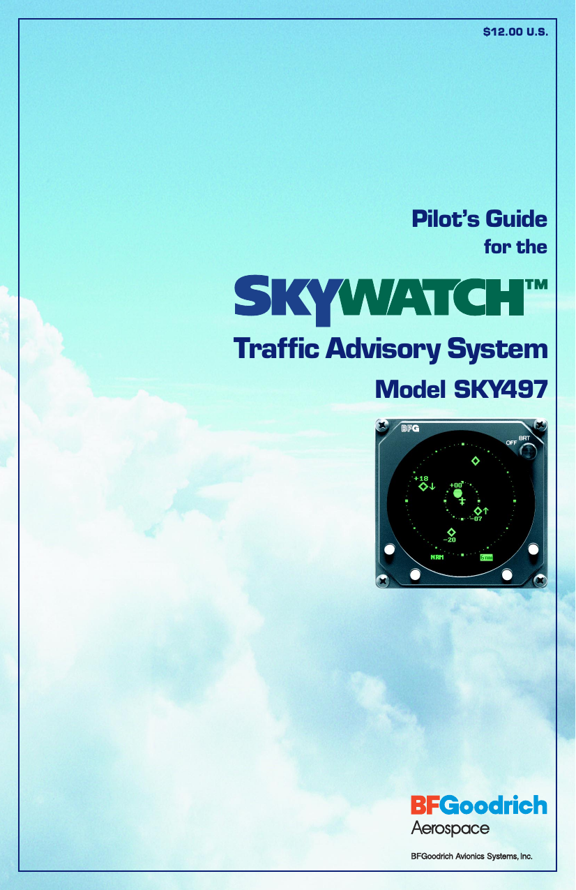
L 3 Communications Avionics Systems TRC497 SkyWatch Traffic Advisory System User Manual Pilot s Guide for SKYWATCH SKY497

L-3 Communications, Avionics Systems SkyWatch Traffic Advisory System Pilot s Guide for SKYWATCH SKY497
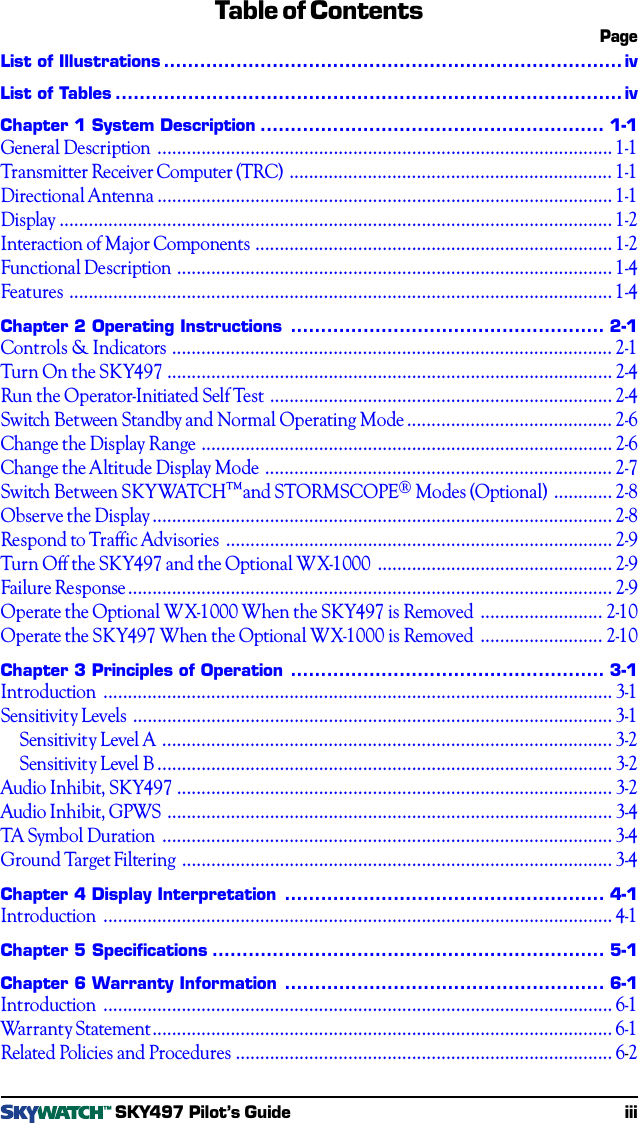
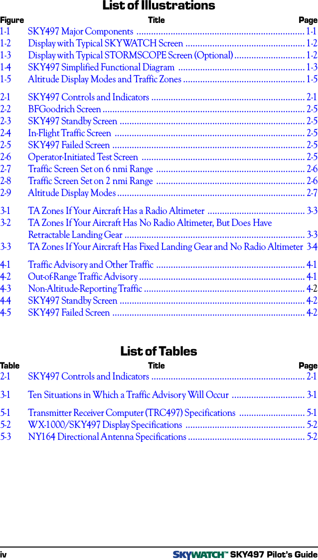
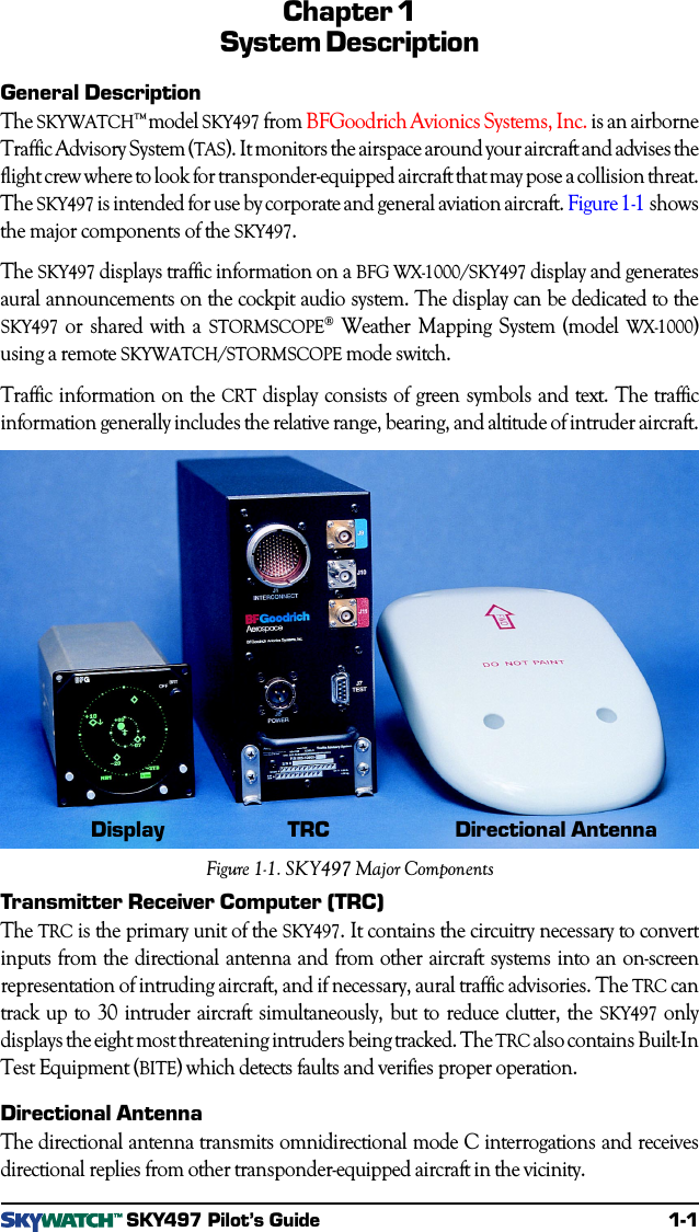
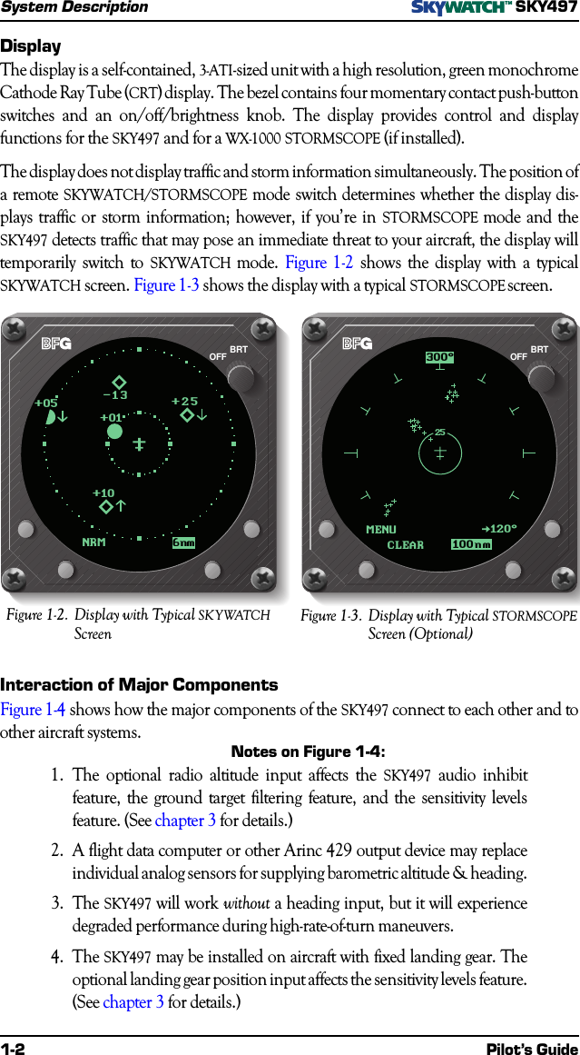
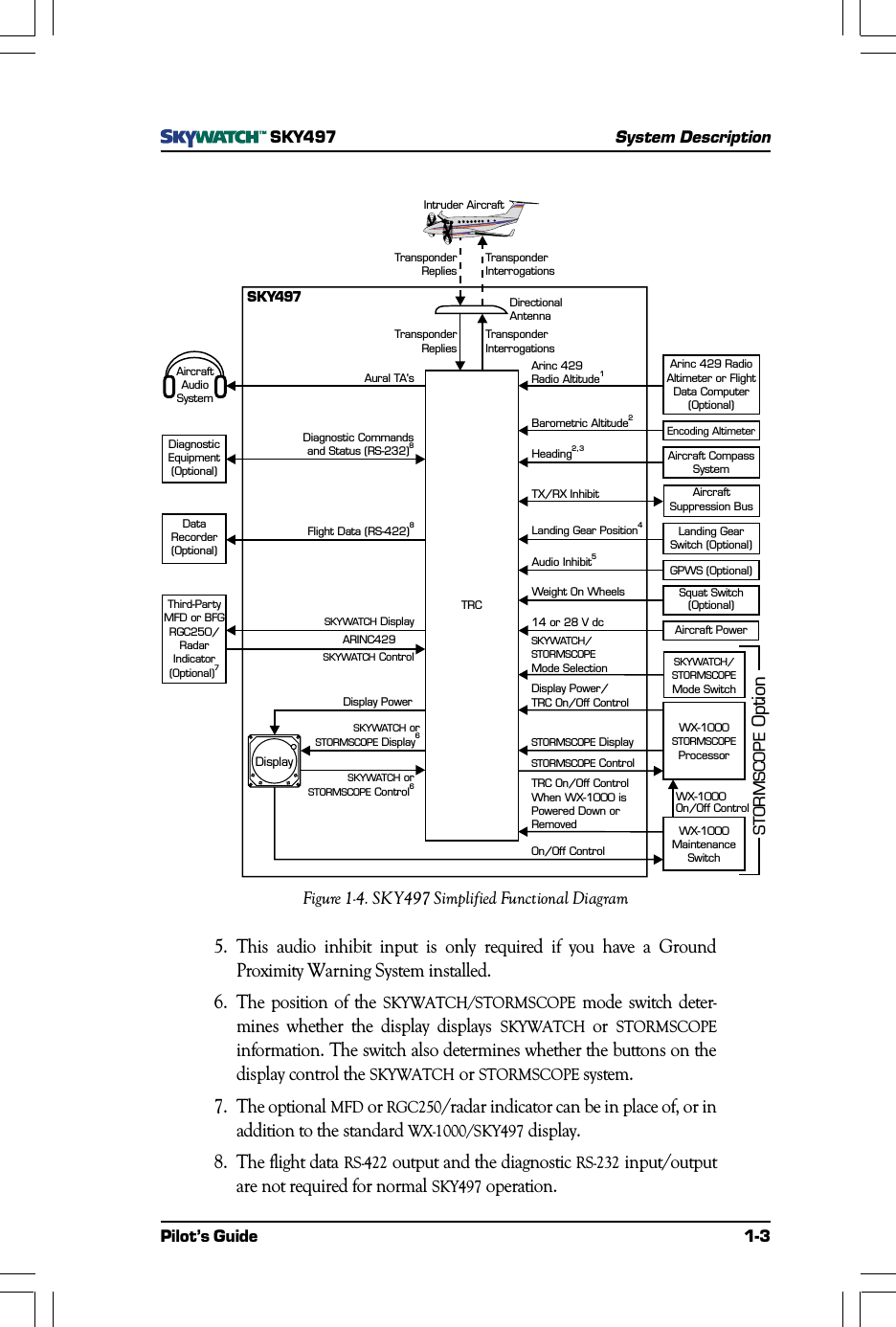
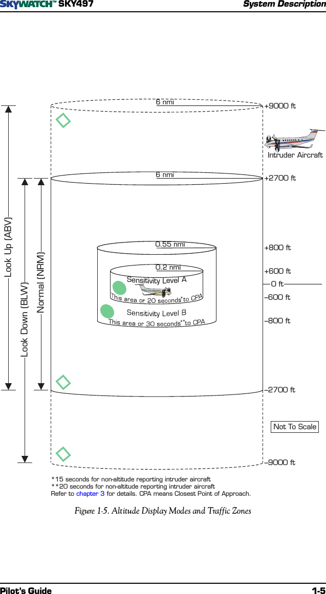
Pilots Guide part 1 of 2

$12.00 U.S.Traffic Advisory SystemPilot’s Guidefor theModel SKY497
EYES THAT NEVER BLINK™Early Traffic Advisory SystemsIn the early days of flight, when air traffic was light and slower moving, pilots wereequipped with all they needed for effective collision avoidance–a sharp pair of eyes to scanthe horizon.Even today, visual contact is still the surest means of identifying intruder aircraft. But withmore traffic in closer proximity and at higher speeds, today’s pilots need all the help theycan get.For large commercial airliners, this need led to the development of TCAS II (Traffic Alertand Collision Avoidance System II); but that technology has proved to be too expensiveand complex for most regional airlines, business, and general aviation aircraft.SKYWATCH™BFGoodrich Avionics Systems, Inc. recognized the need for a viable alternative to TCAS IIand developed their TCAS I; but even TCAS I has proved to be too expensive for smallbusiness and general aviation aircraft. That’s why BFG developed the SKYWATCH™  modelSKY497 Traffic Advisory System.The SKY497 provides most of the capabilities of TCAS I, but at a significantly lower costmaking it practical for small aircraft. In addition, the SKY497 can share the display thatcomes with the STORMSCOPE® model WX-1000 so there’s no need to buy another displayif you already own a WX-1000 display (part number 78-8060-5900-8). The SKY497 can alsodisplay its traffic information on a growing number of multifunction displays fromcompanies such as Avidyne, Eventide, and Garmin. You can even display SKYWATCHtraffic information on a compatible weather radar indicator via the BFG Radar GraphicsComputer, model RGC250.Proven ExperienceBFGoodrich Avionics Systems, Inc. has been involved in the development of collisionwarning programs since the early 1980’s. In 1985, BFG began development of anenhanced collision warning system for the U.S. Navy which awarded BFG a contract forsystems to be installed in T-34C training aircraft.Based largely on the success of the Navy project, BFG was selected to validate thespecifications for TCAS I under an ARINC contract with the FAA. The completion of thiscontract represented another first for BFG’s TCAS I unit, the TCAS791; it was the first TCASI to be TSO’d, first to receive a full, unrestricted STC, first to fly, and first to be delivered.The BFGoodrich tradition of aerospace innovation dates back to the earliest days ofpowered flight when BFG supplied tires for the Glenn Curtiss pusher. Since then, BFG hasdeveloped a wide range of aerospace products and services including flight instrumen-tation and avionics.ASKY497 Pilot’s Guide
$12.00 U.S.modifications, or products at any time without notice.© Copyright 1997, 2000BFGoodrich Avionics Systems, Inc.SKYWATCH™, EYES THAT NEVER BLINK™, and STORMSCOPE® are trademarks ofBFGoodrich Avionics Systems, Inc.Designed and manufactured in the United States of America byMethods and apparatus disclosed and described herein have been developed solely on company funds ofBFGoodrich Avionics Systems, Inc. No government or other contractual support or relationship whatsoever hasexisted which in any way affects or mitigates proprietary rights of BFGoodrich Avionics Systems, Inc. in thesedevelopments. Methods and apparatus disclosed herein may be subject to U.S. Patents existing or applied for.BFGoodrich Avionics Systems, Inc. reserves the right to add, improve, modify, or withdraw functions, designTraffic Advisory SystemPilot’s Guidefor theModel SKY497
ii SKY497 Pilot’s GuideSafety SummaryThese warnings and cautions appear later in this guide and are repeated here for emphasis: (page 2-4)To avoid power surges that could damage the SKY497 and theoptional WX-1000, start your engines before turning on the SKY497. (page 2-8)If the SKY497 is in SKYWATCH mode, the display will not auto-matically switch into STORMSCOPE mode to display thunder-storms or STORMSCOPE errors: You must use the remote SKY-WATCH/STORMSCOPE mode switch to periodically check forthunderstorms or STORMSCOPE errors. (page 2-8)The SKY497 relies on information obtained from transponders innearby aircraft. The SKY497 does not detect or track aircraft whichare not equipped with an operating ATCRBS transponder. (page 2-8)The SKY497 does not track intruder aircraft approaching at aclosure rate greater than 900 knots. (page 2-8)Some traffic within the chosen display range may not be displayeddue to traffic prioritizing or antenna shielding. (page 2-8)Optimum SKY497 performance is realized when intruder aircraftare reporting their altitude (via a mode C or other altitudereporting transponder). (page 2-9)Do not attempt evasive maneuvers based solely on traffic informa-tion shown on the SKY497 display. Information on the display isprovided to the flight crew as an aid in visually acquiring traffic; itis not a replacement for ATC and See & Avoid techniques.
Table of ContentsPageList of Illustrations............................................................................ivList of Tables....................................................................................ivChapter 1 System Description.........................................................1-1General Description.............................................................................................1-1Transmitter Receiver Computer (TRC)..................................................................1-1Directional Antenna.............................................................................................1-1Display.................................................................................................................1-2Interaction of Major Components.........................................................................1-2Functional Description.........................................................................................1-4Features...............................................................................................................1-4Chapter 2 Operating Instructions....................................................2-1Controls & Indicators..........................................................................................2-1Turn On the SKY497...........................................................................................2-4Run the Operator-Initiated Self Test......................................................................2-4Switch Between Standby and Normal Operating Mode..........................................2-6Change the Display Range....................................................................................2-6Change the Altitude Display Mode.......................................................................2-7Switch Between SKYWATCH™  and STORMSCOPE® Modes (Optional)............2-8Observe the Display..............................................................................................2-8Respond to Traffic Advisories...............................................................................2-9Turn Off the SKY497 and the Optional WX-1000................................................2-9Failure Response...................................................................................................2-9Operate the Optional WX-1000 When the SKY497 is Removed.........................2-10Operate the SKY497 When the Optional WX-1000 is Removed.........................2-10Chapter 3 Principles of Operation....................................................3-1Introduction........................................................................................................3-1Sensitivity Levels..................................................................................................3-1Sensitivity Level A............................................................................................3-2Sensitivity Level B.............................................................................................3-2Audio Inhibit, SKY497.........................................................................................3-2Audio Inhibit, GPWS...........................................................................................3-4TA Symbol Duration............................................................................................3-4Ground Target Filtering........................................................................................3-4Chapter 4 Display Interpretation.....................................................4-1Introduction........................................................................................................4-1Chapter 5 Specifications.................................................................5-1Chapter 6 Warranty Information.....................................................6-1Introduction........................................................................................................6-1Warranty Statement..............................................................................................6-1Related Policies and Procedures.............................................................................6-2SKY497 Pilot’s Guide iii
List of IllustrationsFigure Title Page1-1 SKY497 Major Components.....................................................................1-11-2 Display with Typical SKYWATCH Screen.................................................1-21-3 Display with Typical STORMSCOPE Screen (Optional).............................1-21-4 SKY497 Simplified Functional Diagram....................................................1-31-5 Altitude Display Modes and Traffic Zones..................................................1-52-1 SKY497 Controls and Indicators...............................................................2-12-2 BFGoodrich Screen...................................................................................2-52-3 SKY497 Standby Screen............................................................................2-52-4 In-Flight Traffic Screen..............................................................................2-52-5 SKY497 Failed Screen...............................................................................2-52-6 Operator-Initiated Test Screen...................................................................2-52-7 Traffic Screen Set on 6 nmi Range.............................................................2-62-8 Traffic Screen Set on 2 nmi Range.............................................................2-62-9 Altitude Display Modes.............................................................................2-73-1 TA Zones If Your Aircraft Has a Radio Altimeter........................................3-33-2 TA Zones If Your Aircraft Has No Radio Altimeter, But Does HaveRetractable Landing Gear..........................................................................3-33-3 TA Zones If Your Aircraft Has Fixed Landing Gear and No Radio Altimeter3-44-1 Traffic Advisory and Other Traffic.............................................................4-14-2 Out-of-Range Traffic Advisory....................................................................4-14-3 Non-Altitude-Reporting Traffic..................................................................4-24-4 SKY497 Standby Screen............................................................................4-24-5 SKY497 Failed Screen...............................................................................4-2iv SKY497 Pilot’s GuideList of TablesTable Title Page2-1 SKY497 Controls and Indicators...............................................................2-13-1 Ten Situations in Which a Traffic Advisory Will Occur..............................3-15-1 Transmitter Receiver Computer (TRC497) Specifications...........................5-15-2 WX-1000/SKY497 Display Specifications.................................................5-25-3 NY164 Directional Antenna Specifications................................................5-2
SKY497System DescriptionPilot’s Guide 1-1Chapter 1System DescriptionGeneral DescriptionThe SKYWATCH™ model SKY497 from BFGoodrich Avionics Systems, Inc. is an airborneTraffic Advisory System (TAS). It monitors the airspace around your aircraft and advises theflight crew where to look for transponder-equipped aircraft that may pose a collision threat.The SKY497 is intended for use by corporate and general aviation aircraft. Figure 1-1 showsthe major components of the SKY497.The SKY497 displays traffic information on a BFG WX-1000/SKY497 display and generatesaural announcements on the cockpit audio system. The display can be dedicated to theSKY497 or shared with a STORMSCOPE® Weather Mapping System (model WX-1000)using a remote SKYWATCH/STORMSCOPE mode switch.Traffic information on the CRT display consists of green symbols and text. The trafficinformation generally includes the relative range, bearing, and altitude of intruder aircraft.SKY497 Pilot’s GuideTransmitter Receiver Computer (TRC)The TRC is the primary unit of the SKY497. It contains the circuitry necessary to convertinputs from the directional antenna and from other aircraft systems into an on-screenrepresentation of intruding aircraft, and if necessary, aural traffic advisories. The TRC cantrack up to 30 intruder aircraft simultaneously, but to reduce clutter, the SKY497 onlydisplays the eight most threatening intruders being tracked. The TRC also contains Built-InTest Equipment (BITE) which detects faults and verifies proper operation.Directional AntennaThe directional antenna transmits omnidirectional mode C interrogations and receivesdirectional replies from other transponder-equipped aircraft in the vicinity.Figure 1-1. SKY497 Major ComponentsDirectional AntennaTRCDisplay
1-2 Pilot’s GuideSystem DescriptionSKY497DisplayThe display is a self-contained, 3-ATI-sized unit with a high resolution, green monochromeCathode Ray Tube (CRT) display. The bezel contains four momentary contact push-buttonswitches and an on/off/brightness knob. The display provides control and displayfunctions for the SKY497 and for a WX-1000 STORMSCOPE (if installed).The display does not display traffic and storm information simultaneously. The position ofa remote SKYWATCH/STORMSCOPE mode switch determines whether the display dis-plays traffic or storm information; however, if you’re in STORMSCOPE mode and theSKY497 detects traffic that may pose an immediate threat to your aircraft, the display willtemporarily switch to SKYWATCH mode. Figure 1-2 shows the display with a typicalSKYWATCH screen. Figure 1-3 shows the display with a typical STORMSCOPE screen.MENUCLEAR120$25100nm300$BRTOFFNRM 6nm-13+01+25+10+05BRTOFFFigure 1-3.Display with Typical STORMSCOPEScreen (Optional)Figure 1-2.Display with Typical SKYWATCHScreenInteraction of Major ComponentsFigure 1-4 shows how the major components of the SKY497 connect to each other and toother aircraft systems.Notes on Figure 1-4:1.The optional radio altitude input affects the SKY497 audio inhibitfeature, the ground target filtering feature, and the sensitivity levelsfeature. (See chapter 3 for details.)2.A flight data computer or other Arinc 429 output device may replaceindividual analog sensors for supplying barometric altitude & heading.3.The SKY497 will work without a heading input, but it will experiencedegraded performance during high-rate-of-turn maneuvers.4.The SKY497 may be installed on aircraft with fixed landing gear. Theoptional landing gear position input affects the sensitivity levels feature.(See chapter 3 for details.)
SKY497System DescriptionPilot’s Guide 1-35. This audio inhibit input is only required if you have a GroundProximity Warning System installed.6. The position of the SKYWATCH/STORMSCOPE mode switch deter-mines whether the display displays SKYWATCH or STORMSCOPEinformation. The switch also determines whether the buttons on thedisplay control the SKYWATCH or STORMSCOPE system.7. The optional MFD or RGC250/radar indicator can be in place of, or inaddition to the standard WX-1000/SKY497 display.8. The flight data RS-422 output and the diagnostic RS-232 input/outputare not required for normal SKY497 operation.AircraftAudioSystemAircraft PowerFlight Data (RS-422)8SKYWATCHDisplayARINC429SKYWATCHControlDiagnostic Commandsand Status (RS-232)8Arinc 429 RadioAltimeter or FlightData Computer(Optional)SKYWATCH/STORMSCOPEMode SwitchDataRecorder(Optional)Third-PartyMFD or BFGRGC250/RadarIndicator(Optional)7DiagnosticEquipment(Optional)Squat Switch(Optional)GPWS (Optional)Landing GearSwitch (Optional)WX-1000ProcessorSTORMSCOPEWX-1000MaintenanceSwitchAircraft CompassSystemAircraftSuppression BusEncoding AltimeterArinc 429Radio Altitude1SKYWATCH/STORMSCOPEMode SelectionBarometric Altitude2SKYWATCHSTORMSCOPEorDisplay6STORMSCOPEDisplayTRC On/Off ControlWhen WX-1000 isPowered Down orRemovedWX-1000On/Off ControlDisplay Power/TRC On/Off ControlDisplay PowerTRCSKYWATCHSTORMSCOPEorControl6STORMSCOPEControlOn/Off ControlSTORMSCOPEOption14 or 28 V dcAural TA'sHeadingTX/RX InhibitLanding Gear Position4Audio Inhibit5Weight On WheelsDisplayDirectionalAntennaTransponderRepliesTransponderRepliesTransponderInterrogationsSKY497Intruder AircraftTransponderInterrogations2,3Figure 1-4. SKY497 Simplified Functional Diagram
1-4 Pilot’s GuideSystem DescriptionSKY497Functional DescriptionThe SKY497 is an active system that operates as an aircraft-to-aircraft interrogation device.The SKY497 interrogates transponders in the surrounding airspace similar to the way thatground-based radar interrogates aircraft transponders. When the SKY497 receives repliesto its interrogations, it computes the responding aircraft’s range, bearing, relative altitude,and closure rate. The SKY497 then plots the traffic location and predicts collision threats.Figure 1-5 shows the SKY497 altitude display modes (look up, look down, and normal).The figure also shows the traffic zones around your aircraft and the traffic symbols thatappear on the display when intruding aircraft enter one of those zones.A solid circle is the visual part of the Traffic Advisory (TA) that the SKY497 generates whenit predicts that an intruder aircraft may pose a collision threat. The aural part of the TA,“traffic, traffic,” is annunciated over a cockpit speaker or headset. An open diamondrepresents traffic that does not pose an immediate collision threat.The SKY497 uses either sensitivity level A (SLA) or sensitivity level B (SLB) to determinewhen to display a TA. In general, SLB is used during the in-flight phase and SLA is usedduring takeoff and landing. Sensitivity levels and other factors affecting the display of trafficsymbols are discussed in detail in chapter 3. Look up, look down, and normal altitudedisplay modes are described in chapter 2.Features• Tracks up to 30 intruder aircraft (displays the 8 most threatening)• Tracks intruder aircraft approaching at closure rates up to 900 knots• Fraction of the cost of a TCAS I or II• Does not require a mode S transponder• Two horizontal display ranges (6 nmi and 2 nmi)• Three altitude display modes: normal (±2,700 ft), look up (–2,700 ft to +9,000 ft), andlook down (–9,000 ft to +2,700 ft)• Generates visual and aural advisories of aircraft that may pose a collision threat• Automatic and pilot-initiated self test functions• High-resolution, green monochrome, CRT display• Can transmit interrogations from the ground as well as from the air• Can share a display with the STORMSCOPE WX-1000• Can display its traffic information on a compatible weather radar indicator (via a BFGRGC250) or on a third-party multifunction display in addition to, or in place of theBFG display.• Automatically switches back to the SKYWATCH screen from the STORMSCOPEscreen when a TA is issued• Uses only one antenna• Display fits in a standard 3-ATI cutout in the cockpit panel
SKY497System DescriptionPilot’s Guide 1-5Figure 1-5. Altitude Display Modes and Traffic Zones0.2 nmi0.55 nmi6 nmi+2700 ft–2700 ft+9000 ftIntruder Aircraft–9000 ft*15 seconds for non-altitude reporting intruder aircraftNot To Scale+800 ft–800 ft+600 ft–600 ft6 nmiSensitivityLevelALook Down (BLW)Look Up (ABV)Normal (NRM)0 ft**20 seconds for non-altitude reporting intruder aircraftRefer to chapter 3 for details. CPA means Closest Point of Approach.***

Navigation menu