L 3 Communications Avionics Systems TRC497 SkyWatch Traffic Advisory System User Manual COVER

L-3 Communications, Avionics Systems SkyWatch Traffic Advisory System COVER

Install Manual part 1 of 3
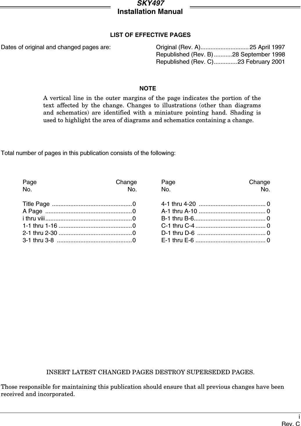
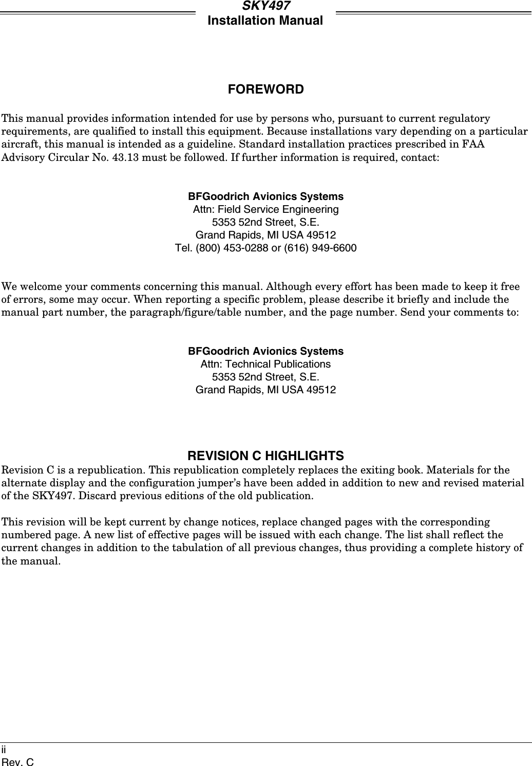
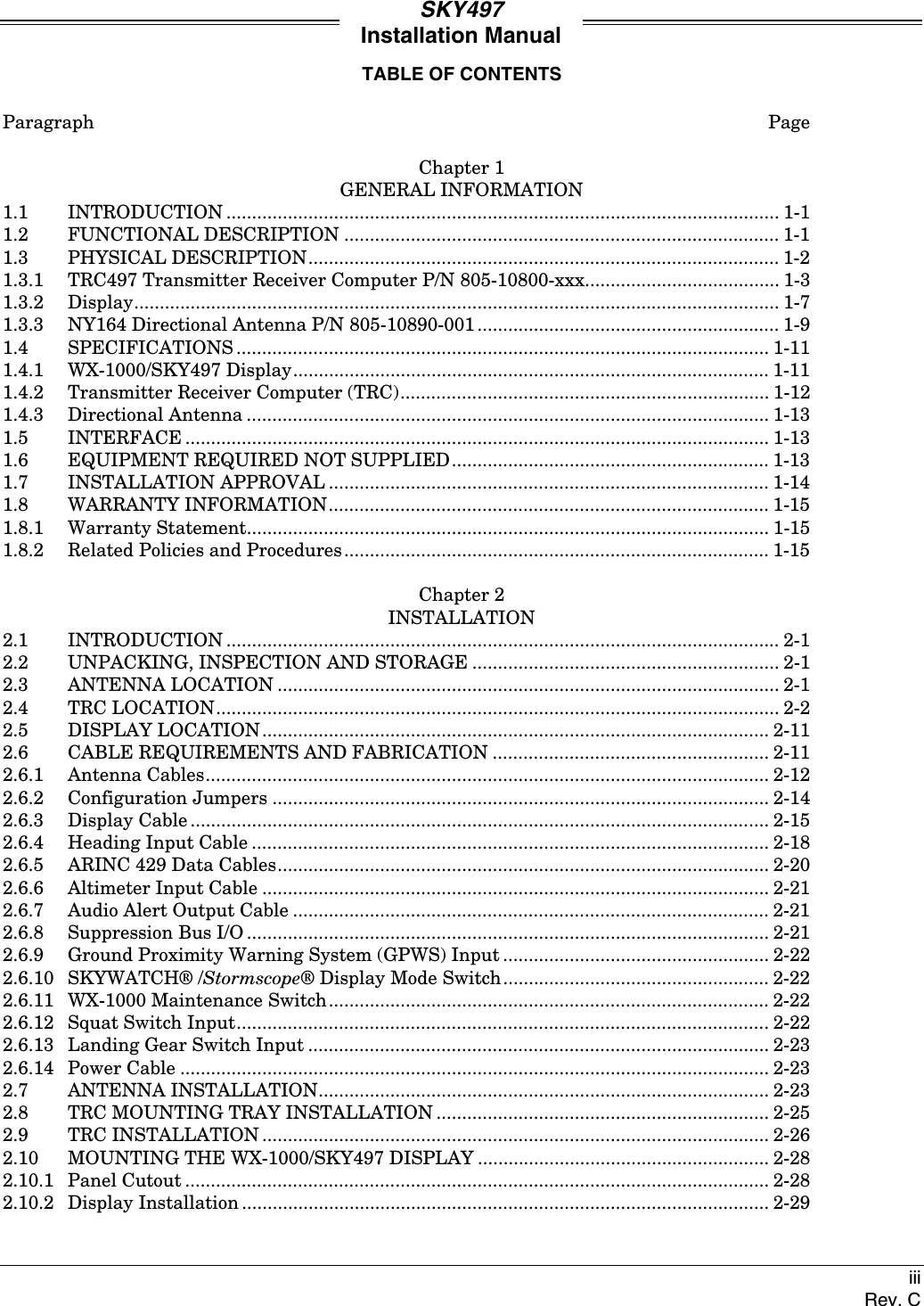
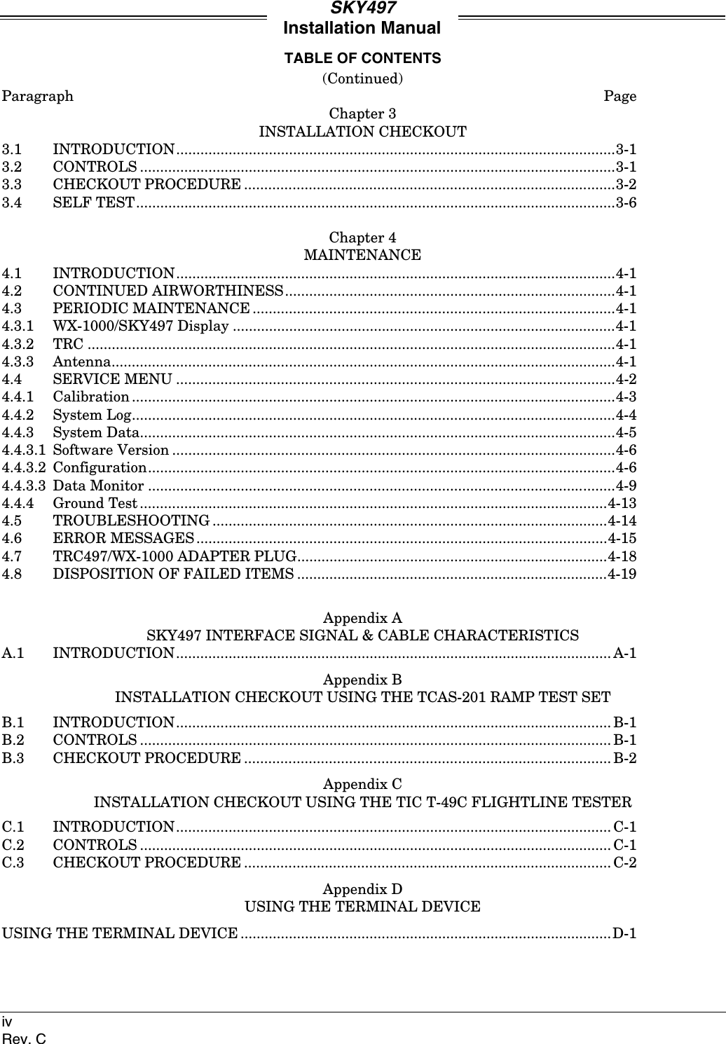
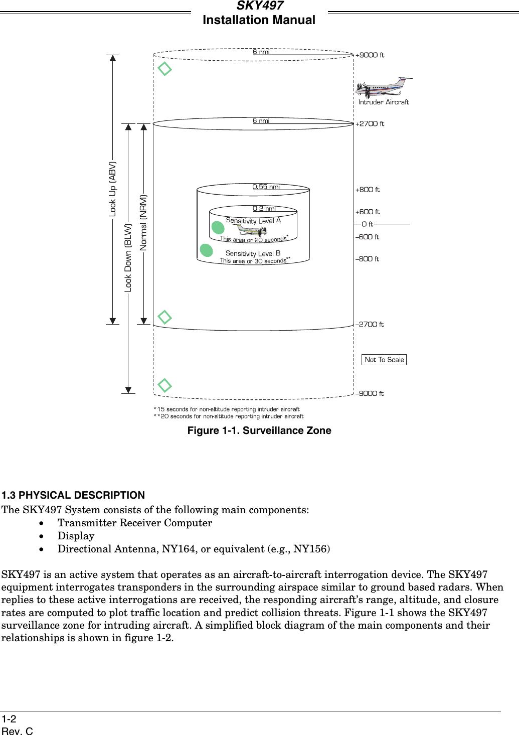
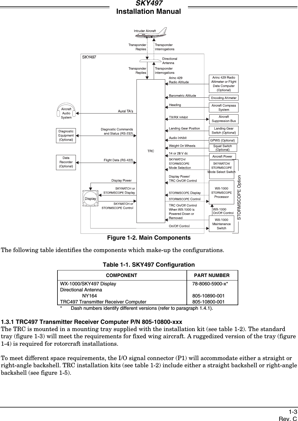
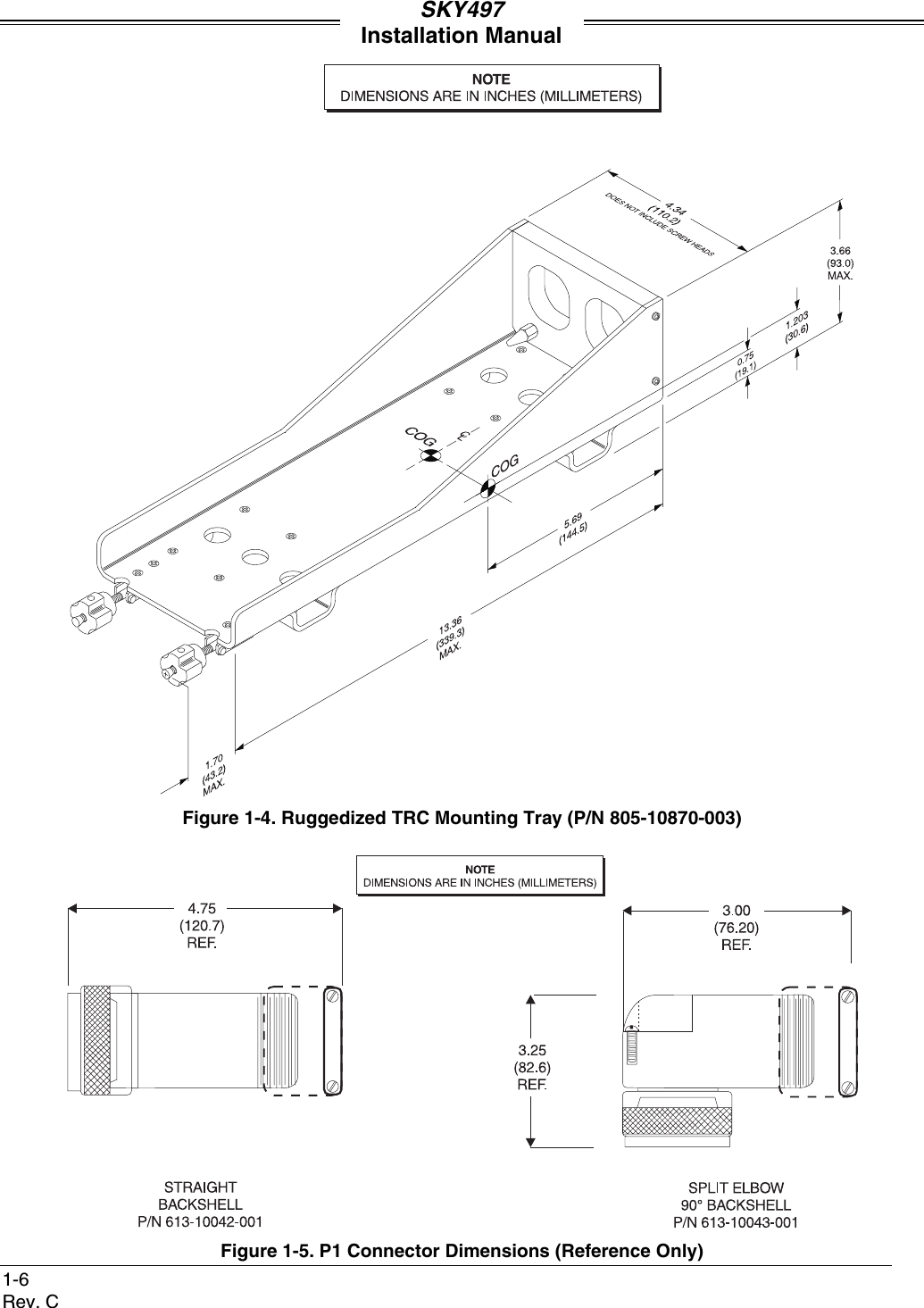
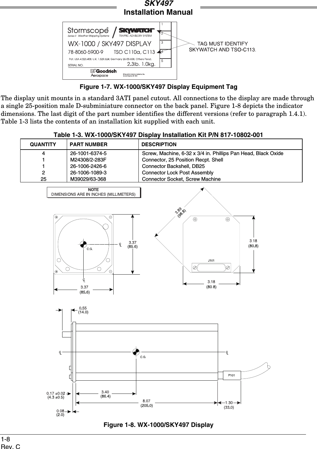
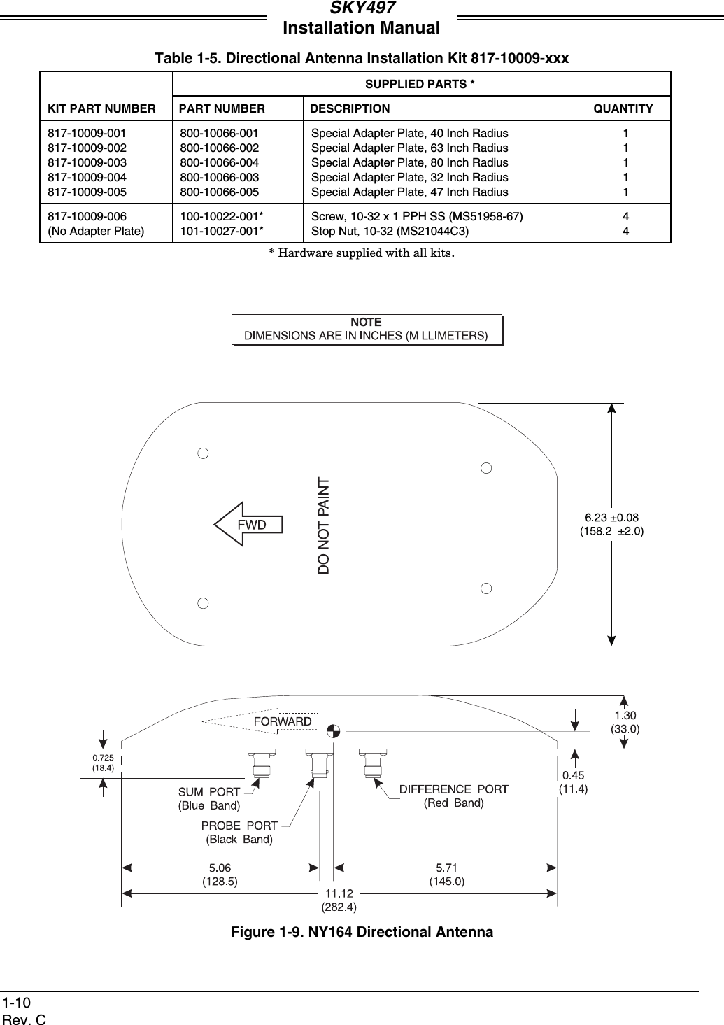
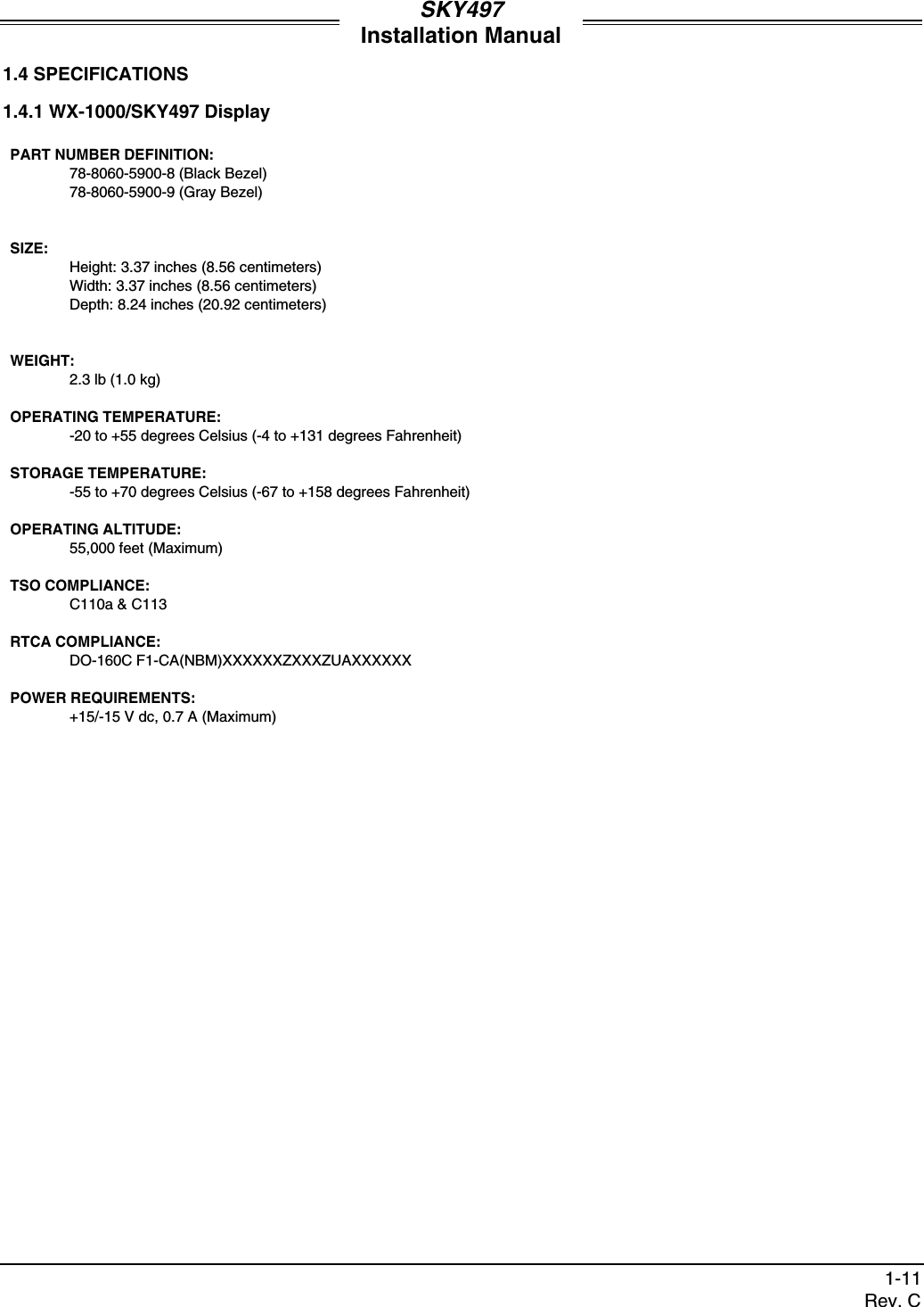
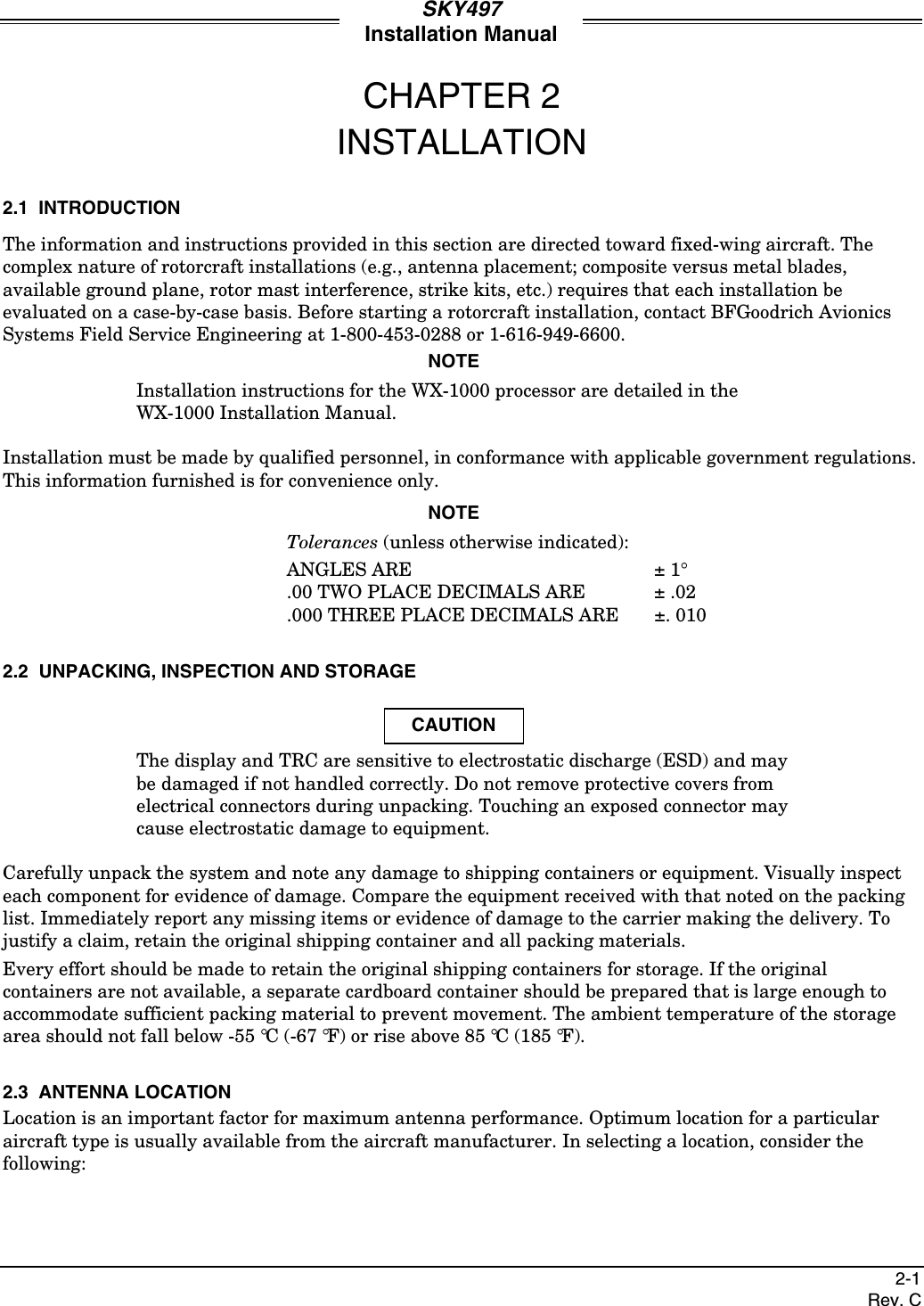
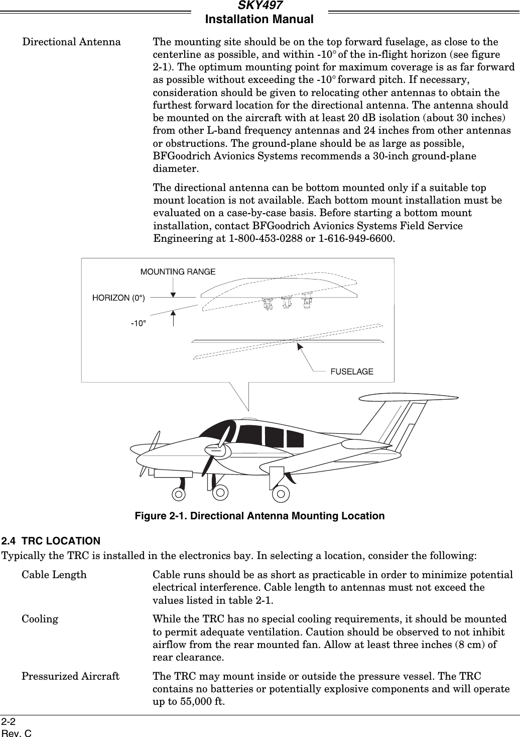
Traffic Advisory SystemSKY497InstallationManualThis manual contains installation instructions andrecommended flightline maintenance information for theSKY429 Traffic Advisory System. This information issupplemented and kept current by Change Notices andService Bulletins published by BFGoodrich AvionicsSystems.009-10800-001 (Rev. C)BFGoodrich Avionics Systems, Inc. 23 February 20015353 52nd Street, S.E.Grand Rapids, MI USA 49512
ARev. CABOUT THIS MANUALChapter 1 – General InformationThis chapter includes equipment specifications and a functional description. It describes the varioushardware configurations and includes a list of items furnished and items required but not suppliedwith the equipment.Chapter 2 - InstallationThis chapter contains instructions for unpacking the equipment and inspection for in-shipmentdamage. It also includes information required to locate, assemble and install the equipment.Chapter 3 – Installation CheckoutThis chapter contains instructions for doing post-installation and return to service checkout of theSKY497 using the BFGoodrich Avionics Systems TT391 Flightline Tester.Chapter 4 – MaintenanceThis chapter contains general flightline maintenance procedures. It includes periodic maintenance andtroubleshooting; instructions for calibrating the directional antenna and instructions for the return ofdefective components.Appendix A – Signal and Cable CharacteristicsThis appendix defines the electrical characteristics of all input and output signals.Appendix B – Installation Checkout Using The TCAS-201 Ramp Test SetThis appendix contains instructions for doing post-installation and return to service checkout of theSKY497 using the IFR Systems TCAS-201 Ramp Test Set (with TCAS I firmware).Appendix C – Installation Checkout Using The TIC T-49C Flightline TesterThis appendix contains instructions for doing post-installation and return to service checkout of theSKY497 using the TIC T-49C Flightline Tester.Appendix D – Using The Terminal DeviceThis appendix contains instructions for using the Terminal Device for installation, testing ortroubleshooting of the SKY497.Appendix E – Installation Checkout Using an Alternate DisplayThis appendix contains instructions for doing post-installation and return to service checkout of theSKY497 using an Alternate Display.© Copyright 1997-2001BFGoodrich Avionics Systems____________________________TrademarksLoctite® is a registered trademark of Loctite Corporation.Mylar® and Teflon® are registered trademarks of DuPont.Flamemaster® is a registered trademark of Flamemaster Corporation.Rivnut® is a registered trademark of Rivnut Engineered Products, Inc.SKYWATCH® and Stormscope® are registered trademarks of BFGoodrich Avionics Systems, Inc.
SKY497Installation ManualiRev. CLIST OF EFFECTIVE PAGESDates of original and changed pages are: Original (Rev. A)............................. 25 April 1997Republished (Rev. B)...........28 September 1998Republished (Rev. C)..............23 February 2001NOTEA vertical line in the outer margins of the page indicates the portion of thetext affected by the change. Changes to illustrations (other than diagramsand schematics) are identified with a miniature pointing hand. Shading isused to highlight the area of diagrams and schematics containing a change.Total number of pages in this publication consists of the following:Page ChangeNo. No.Title Page ................................................0A Page  ....................................................0i thru viii....................................................01-1 thru 1-16 ............................................02-1 thru 2-30 ............................................03-1 thru 3-8  .............................................0Page ChangeNo. No.4-1 thru 4-20  ........................................ 0A-1 thru A-10 ........................................ 0B-1 thru B-6........................................... 0C-1 thru C-4 .......................................... 0D-1 thru D-6  ......................................... 0E-1 thru E-6 .......................................... 0INSERT LATEST CHANGED PAGES DESTROY SUPERSEDED PAGES.Those responsible for maintaining this publication should ensure that all previous changes have beenreceived and incorporated.
SKY497Installation ManualiiRev. CFOREWORDThis manual provides information intended for use by persons who, pursuant to current regulatoryrequirements, are qualified to install this equipment. Because installations vary depending on a particularaircraft, this manual is intended as a guideline. Standard installation practices prescribed in FAAAdvisory Circular No. 43.13 must be followed. If further information is required, contact:BFGoodrich Avionics SystemsAttn: Field Service Engineering5353 52nd Street, S.E.Grand Rapids, MI USA 49512Tel. (800) 453-0288 or (616) 949-6600We welcome your comments concerning this manual. Although every effort has been made to keep it freeof errors, some may occur. When reporting a specific problem, please describe it briefly and include themanual part number, the paragraph/figure/table number, and the page number. Send your comments to:BFGoodrich Avionics SystemsAttn: Technical Publications5353 52nd Street, S.E.Grand Rapids, MI USA 49512REVISION C HIGHLIGHTSRevision C is a republication. This republication completely replaces the exiting book. Materials for thealternate display and the configuration jumper’s have been added in addition to new and revised materialof the SKY497. Discard previous editions of the old publication.This revision will be kept current by change notices, replace changed pages with the correspondingnumbered page. A new list of effective pages will be issued with each change. The list shall reflect thecurrent changes in addition to the tabulation of all previous changes, thus providing a complete history ofthe manual.
SKY497Installation ManualiiiRev. CTABLE OF CONTENTSParagraph PageChapter 1GENERAL INFORMATION1.1 INTRODUCTION ............................................................................................................ 1-11.2 FUNCTIONAL DESCRIPTION ..................................................................................... 1-11.3 PHYSICAL DESCRIPTION............................................................................................ 1-21.3.1 TRC497 Transmitter Receiver Computer P/N 805-10800-xxx...................................... 1-31.3.2 Display.............................................................................................................................. 1-71.3.3 NY164 Directional Antenna P/N 805-10890-001........................................................... 1-91.4 SPECIFICATIONS ........................................................................................................ 1-111.4.1 WX-1000/SKY497 Display............................................................................................. 1-111.4.2 Transmitter Receiver Computer (TRC)........................................................................ 1-121.4.3 Directional Antenna ...................................................................................................... 1-131.5 INTERFACE .................................................................................................................. 1-131.6 EQUIPMENT REQUIRED NOT SUPPLIED.............................................................. 1-131.7 INSTALLATION APPROVAL ...................................................................................... 1-141.8 WARRANTY INFORMATION...................................................................................... 1-151.8.1 Warranty Statement...................................................................................................... 1-151.8.2 Related Policies and Procedures................................................................................... 1-15Chapter 2INSTALLATION2.1 INTRODUCTION ............................................................................................................ 2-12.2 UNPACKING, INSPECTION AND STORAGE ............................................................ 2-12.3 ANTENNA LOCATION .................................................................................................. 2-12.4 TRC LOCATION.............................................................................................................. 2-22.5 DISPLAY LOCATION................................................................................................... 2-112.6 CABLE REQUIREMENTS AND FABRICATION ...................................................... 2-112.6.1 Antenna Cables.............................................................................................................. 2-122.6.2 Configuration Jumpers ................................................................................................. 2-142.6.3 Display Cable ................................................................................................................. 2-152.6.4 Heading Input Cable ..................................................................................................... 2-182.6.5 ARINC 429 Data Cables................................................................................................ 2-202.6.6 Altimeter Input Cable ................................................................................................... 2-212.6.7 Audio Alert Output Cable ............................................................................................. 2-212.6.8 Suppression Bus I/O...................................................................................................... 2-212.6.9 Ground Proximity Warning System (GPWS) Input .................................................... 2-222.6.10 SKYWATCH®  /Stormscope®  Display Mode Switch.................................................... 2-222.6.11 WX-1000 Maintenance Switch...................................................................................... 2-222.6.12 Squat Switch Input........................................................................................................2-222.6.13 Landing Gear Switch Input .......................................................................................... 2-232.6.14 Power Cable ................................................................................................................... 2-232.7 ANTENNA INSTALLATION........................................................................................ 2-232.8 TRC MOUNTING TRAY INSTALLATION ................................................................. 2-252.9 TRC INSTALLATION ................................................................................................... 2-262.10 MOUNTING THE WX-1000/SKY497 DISPLAY ......................................................... 2-282.10.1 Panel Cutout .................................................................................................................. 2-282.10.2 Display Installation ....................................................................................................... 2-29
SKY497Installation ManualivRev. CTABLE OF CONTENTS(Continued)Paragraph PageChapter 3INSTALLATION CHECKOUT3.1 INTRODUCTION.............................................................................................................3-13.2 CONTROLS ......................................................................................................................3-13.3 CHECKOUT PROCEDURE ............................................................................................3-23.4 SELF TEST.......................................................................................................................3-6Chapter 4MAINTENANCE4.1 INTRODUCTION.............................................................................................................4-14.2 CONTINUED AIRWORTHINESS..................................................................................4-14.3 PERIODIC MAINTENANCE ..........................................................................................4-14.3.1 WX-1000/SKY497 Display ...............................................................................................4-14.3.2 TRC ...................................................................................................................................4-14.3.3 Antenna.............................................................................................................................4-14.4 SERVICE MENU .............................................................................................................4-24.4.1 Calibration ........................................................................................................................4-34.4.2 System Log........................................................................................................................4-44.4.3 System Data......................................................................................................................4-54.4.3.1 Software Version ..............................................................................................................4-64.4.3.2 Configuration....................................................................................................................4-64.4.3.3 Data Monitor ....................................................................................................................4-94.4.4 Ground Test ....................................................................................................................4-134.5 TROUBLESHOOTING ..................................................................................................4-144.6 ERROR MESSAGES......................................................................................................4-154.7 TRC497/WX-1000 ADAPTER PLUG.............................................................................4-184.8 DISPOSITION OF FAILED ITEMS .............................................................................4-19Appendix ASKY497 INTERFACE SIGNAL & CABLE CHARACTERISTICSA.1 INTRODUCTION............................................................................................................A-1Appendix BINSTALLATION CHECKOUT USING THE TCAS-201 RAMP TEST SETB.1 INTRODUCTION............................................................................................................B-1B.2 CONTROLS .....................................................................................................................B-1B.3 CHECKOUT PROCEDURE ...........................................................................................B-2Appendix CINSTALLATION CHECKOUT USING THE TIC T-49C FLIGHTLINE TESTERC.1 INTRODUCTION............................................................................................................C-1C.2 CONTROLS .....................................................................................................................C-1C.3 CHECKOUT PROCEDURE ...........................................................................................C-2Appendix DUSING THE TERMINAL DEVICEUSING THE TERMINAL DEVICE ............................................................................................D-1
SKY497Installation ManualvRev. CTABLE OF CONTENTS(Continued)Paragraph PageAppendix EINSTALLATION CHECKOUT USING AN ALTERNATE DISPLAYE.1 INTRODUCTION ............................................................................................................E-1E.2 CONTROLS......................................................................................................................E-1E.3 CHECKOUT PROCEDURE............................................................................................E-1E.3.1 Self Test............................................................................................................................E-5
SKY497Installation ManualviRev. CLIST OF ILLUSTRATIONSFigure Page1-1 Surveillance Zone .............................................................................................................1-21-2 Main Components ............................................................................................................1-31-3 Standard TRC Mounting Tray (P/N 805-10870-001) .....................................................1-51-4 Ruggedized TRC Mounting Tray (P/N 805-10870-003)..................................................1-61-5 P1 Connector Dimensions (Reference Only)...................................................................1-61-6 TRC Transmitter Receiver Computer (TRC)..................................................................1-71-7 WX-1000/SKY497 Display Equipment Tag ....................................................................1-81-8 WX-1000/SKY497 Display ...............................................................................................1-81-9 NY164 Directional Antenna ..........................................................................................1-102-1 Directional Antenna Mounting Location ........................................................................2-22-2 Interconnect Wiring Without WX-1000 ..........................................................................2-32-3 Interconnect Wiring With WX-1000................................................................................2-72-4 Connector P1 Contact Arrangement .............................................................................2-142-5 Display Cable..................................................................................................................2-172-6 KCS55 Heading Flag Connection..................................................................................2-182-7 Heading Input Cable......................................................................................................2-192-8 Antenna Mounting Holes...............................................................................................2-242-9 Directional Antenna Installation ..................................................................................2-242-10 Mounting Holes for Standard Mount Tray, P/N 805-10870-001 .................................2-252-11 Mounting Holes for Ruggedized Mount Tray, P/N 805-10870-003 .............................2-252-12 TRC Installation.............................................................................................................2-272-13 Instrument Panel Cutout and Mounting Holes............................................................2-282-14 Display Installation........................................................................................................2-293-1 Controls.............................................................................................................................3-13-2 Start-up Screen.................................................................................................................3-23-3 Standby Screen.................................................................................................................3-33-4 Typical Patch Antenna Tripod Mount.............................................................................3-53-5 Self Test Screen ................................................................................................................3-63-6 Self Test Failed Screen ....................................................................................................3-74-1 Service Menu ....................................................................................................................4-24-2 Calibration Screen............................................................................................................4-34-3 Successful Re-Calibration................................................................................................4-34-4 Failed Calibration ............................................................................................................4-44-5 System Log........................................................................................................................4-44-6 System Data......................................................................................................................4-54-7 Software Version ..............................................................................................................4-64-8 Configuration - Page 1 .....................................................................................................4-74-9 Configuration - Page 2 .....................................................................................................4-84-10 Configuration - Page 3 .....................................................................................................4-84-11 Configuration - Page 4 .....................................................................................................4-94-12 Data Monitor - Page 1 ....................................................................................................4-104-13 Data Monitor - Page 2 ....................................................................................................4-104-14 Data Monitor - Page 3 ....................................................................................................4-114-15 Data Monitor - Page 4 ....................................................................................................4-124-16 Data Monitor - Page 5 ....................................................................................................4-124-17 Ground Test....................................................................................................................4-134-18 Adapter Plug Jumper Installation ................................................................................4-184-19 Adapter Plug Assembly..................................................................................................4-18
SKY497Installation ManualviiRev. CLIST OF ILLUSTRATIONS(Continued)Figure PageB-1 Controls ............................................................................................................................B-1B-2 Start-up Screen................................................................................................................B-3B-3 Standby Screen ................................................................................................................B-3C-1 Controls ............................................................................................................................C-1C-2 Start-up Screen................................................................................................................C-2C-3 Standby Screen ................................................................................................................C-3E-1 Typical Patch Antenna Tripod Mount............................................................................E-3LIST OF TABLESTable Page1-1 SKY497 Configuration .................................................................................................... 1-31-2 TRC Installation Kit P/N 817-10800-xxx ....................................................................... 1-41-3 WX-1000/SKY497 Display Installation Kit P/N 817-10802-001 ................................... 1-81-4 Airframe Installation Kits............................................................................................... 1-91-5 Directional Installation Kit 817-10009-xxx.................................................................. 1-102-1 Directional Antenna SIGMA and DELTA Port Cable Vendors.................................. 2-122-2 Cable to Connector Reference....................................................................................... 2-132-3 Configuration Jumpers ................................................................................................. 2-142-4 Heading Flag Action...................................................................................................... 2-152-5 WX-1000/SKY497 Display Connection......................................................................... 2-152-6 WX-1000 Processor Connection .................................................................................... 2-162-7 Display Cable Vendors .................................................................................................. 2-162-8 Heading Input Cable Vendors ...................................................................................... 2-194-1 Fault Isolation................................................................................................................ 4-144-2 Installation Related Error Messages............................................................................ 4-154-3 Informational Error Messages...................................................................................... 4-174-4 Adapter Plug Jumpers................................................................................................... 4-18B-1 IFR Systems TCAS-201 Ramp Test Set Setup Data .....................................................B-2
SKY497Installation ManualviiiRev. CThis page intentionally left blank.
SKY497Installation Manual1-1Rev. CCHAPTER 1GENERAL INFORMATION1.1 INTRODUCTIONThis section contains a functional description of the SKY497, describes the various hardware and softwareconfigurations, outlines the main features of the system, and provides a system block diagram.NOTES1. This section provides installation information for the BFGoodrich Avionics SystemsSKY497 using the WX-1000/SKY497 Display.2. The SKY497 does not track intruder aircraft approaching at a closure rate greaterthan 900 knots.3. The SKY497 can be interfaced to an alternate display device (i.e., MFD, weatherradar indicator), contact BFGoodrich Avionics Systems Field Service Engineering at1-800-453-0288 or 1-616-949-6600 for approved displays and software versionrequired for the TRC497.4. The SKY497 can be interfaced to a weather radar indicator in place of theWX-1000/SKY497 display, by using the BFGoodrich Avionics Systems RGC250(Radar Graphics Computer). Refer to the RGC250 Installation Manual for details.5. An alternate display device can be used in place of the WX-1000/SKY497 display asthe primary means of displaying traffic information. Refer to manufacturerinstructions for installation details.6. When an alternate display device is installed the service menu can not be accessed,therefore a terminal device (i.e., laptop) is required for post-installation checkout(refer to appendix E).1.2 FUNCTIONAL DESCRIPTIONThe BFG Avionics Systems SKY497 is an airborne traffic advisory system that advises the flight crewwhere to look for aircraft that may pose a collision threat. It is intended for use by corporate and generalaviation aircraft. SKY497 alerts the flight crew to nearby transponder equipped aircraft and assists thepilot in the visual acquisition of aircraft that may represent a danger.Traffic information, out to a selected range of either 2 or 6 nautical miles, is graphically displayed on theCRT. Using shapes (i.e., Traffic Advisory = solid circle; Other Traffic = open diamond) and text, the displayshows the relative position of threat aircraft.
SKY497Installation Manual1-2Rev. CFigure 1-1. Surveillance Zone1.3 PHYSICAL DESCRIPTIONThe SKY497 System consists of the following main components:• Transmitter Receiver Computer• Display• Directional Antenna, NY164, or equivalent (e.g., NY156)SKY497 is an active system that operates as an aircraft-to-aircraft interrogation device. The SKY497equipment interrogates transponders in the surrounding airspace similar to ground based radars. Whenreplies to these active interrogations are received, the responding aircraft’s range, altitude, and closurerates are computed to plot traffic location and predict collision threats. Figure 1-1 shows the SKY497surveillance zone for intruding aircraft. A simplified block diagram of the main components and theirrelationships is shown in figure 1-2.
SKY497Installation Manual1-3Rev. CFigure 1-2. Main ComponentsThe following table identifies the components which make-up the configurations.Table 1-1. SKY497 ConfigurationCOMPONENT PART NUMBERWX-1000/SKY497 Display 78-8060-5900-x*Directional AntennaNY164 805-10890-001TRC497 Transmitter Receiver Computer 805-10800-001* Dash numbers identify different versions (refer to paragraph 1.4.1).1.3.1 TRC497 Transmitter Receiver Computer P/N 805-10800-xxxThe TRC is mounted in a mounting tray supplied with the installation kit (see table 1-2). The standardtray (figure 1-3) will meet the requirements for fixed wing aircraft. A ruggedized version of the tray (figure1-4) is required for rotorcraft installations.To meet different space requirements, the I/O signal connector (P1) will accommodate either a straight orright-angle backshell. TRC installation kits (see table 1-2) include either a straight backshell or right-anglebackshell (see figure 1-5).
SKY497Installation Manual1-4Rev. CTable 1-2. TRC Installation Kit P/N 817-10800-xxxKIT P/N DESCRIPTION QUANTITY PART NUMBERFor Installation on Fixed-Wing Aircraft with Straight BackshellConsists of:Mounting Tray Assembly 805-10870-0014.75 In. Straight Backshell 613-10042-001I/O Connector, 100-Position, Female, (Mil-C-38999 Series III) 1 605-10205-001(Includes #22D Crimp Terminals)Spare Terminals for I/O Connector 10 M39029/56-348Power Connector, 3-Position, Straight Plug 1 MS3126F12-3S(Includes #16 Crimp Terminals)817-10800-002Spare Terminals for Power Connector (M39029/32-247) 2 607-10018-001For Installation on Fixed-Wing Aircraft with Right-Angle BackshellConsists of:Mounting Tray Assembly 805-10870-001Right-Angle Backshell 613-10043-001I/O Connector, 100-Position, Female, (Mil-C-38999 Series III) 1 605-10205-001(Includes #22D Crimp Terminals)Spare Terminals for I/O Connector 10 M39029/56-348Power Connector, 3-Position, Straight Plug 1 MS3126F12-3S(Includes #16 Crimp Terminals)817-10800-003Spare Terminals for Power Connector (M39029/32-247) 2 607-10018-001For Installation on Rotorcraft with Straight BackshellConsists of:Mounting Tray Assembly 805-10870-0034.75 In. Straight Backshell 613-10042-001I/O Connector, 100-Position, Female, (Mil-C-38999 Series III) 1 605-10205-001(Includes #22D Crimp Terminals)Spare Terminals for I/O Connector 10 M39029/56-348Power Connector, 3-Position, Straight Plug 1 MS3126F12-3S(Includes #16 Crimp Terminals)817-10800-004Spare Terminals for Power Connector (M39029/32-247) 2 607-10018-001For Installation on Rotorcraft with Right-Angle BackshellConsists of:Mounting Tray Assembly 805-10870-003Right-Angle Backshell 613-10043-001I/O Connector, 100-Position, Female, (Mil-C-38999 Series III) 1 605-10205-001(Includes #22D Crimp Terminals)Spare Terminals for I/O Connector 10 M39029/56-348Power Connector, 3-Position, Straight Plug 1 MS3126F12-3S(Includes #16 Crimp Terminals)817-10800-005Spare Terminals for Power Connector (M39029/32-247) 2 607-10018-001
SKY497Installation Manual1-5Rev. CFigure 1-3. Standard TRC Mounting Tray (P/N 805-10870-001)
SKY497Installation Manual1-6Rev. CFigure 1-4. Ruggedized TRC Mounting Tray (P/N 805-10870-003)Figure 1-5. P1 Connector Dimensions (Reference Only)
SKY497Installation Manual1-7Rev. CFigure 1-6. TRC497 Transmitter Receiver Computer (TRC)1.3.2 DisplayThe SKY497 can be used with a WX-1000/SKY497 display, an alternate display device or both. Wheninterfaced to both displays (WX-1000/SKY497 display and alternate display), display functions areindependent from each other. When installing an alternate display device the service menu cannot beaccessed, even if a WX-1000/SKY497 display is installed, therefore a terminal device (i.e., laptop) isrequired for post-installation checkout (see appendix E).The SKY497 is designed to transmit traffic information to the alternate display device via our ARINC-429bus interface. Refer to display manufacturer instructions for installation details.WX-1000/SKY497 Display P/N 78-8060-5900-x. To operate with SKYWATCH, existing WX-1000 displaysmust conform to TSO-C113. If the equipment tag on the back of the unit (see figure 1-7) does not identifySKYWATCH and TSO-C113, return the display to the factory for modification. To schedule workload andensure a quick turn around, a return authorization will be required. Call BFG Avionics Systems CustomerService (1-800-453-0288 or 1-616-949-6600) for details.
SKY497Installation Manual1-8Rev. CFigure 1-7. WX-1000/SKY497 Display Equipment TagThe display unit mounts in a standard 3ATI panel cutout. All connections to the display are made througha single 25-position male D-subminiature connector on the back panel. Figure 1-8 depicts the indicatordimensions. The last digit of the part number identifies the different versions (refer to paragraph 1.4.1).Table 1-3 lists the contents of an installation kit supplied with each unit.Table 1-3. WX-1000/SKY497 Display Installation Kit P/N 817-10802-001QUANTITY PART NUMBER DESCRIPTION4 26-1001-6374-5 Screw, Machine, 6-32 x 3/4 in. Phillips Pan Head, Black Oxide1 M24308/2-283F Connector, 25 Position Recpt. Shell1 26-1006-2426-6 Connector Backshell, DB252 26-1006-1089-3 Connector Lock Post Assembly25 M39029/63-368 Connector Socket, Screw MachineFigure 1-8. WX-1000/SKY497 Display
SKY497Installation Manual1-9Rev. C1.3.3 NY-164 Directional Antenna P/N 805-10890-001The directional antenna is a teardrop-shaped antenna. Connections are made through two TNC and oneBNC connector. The antenna is sealed against environmental extremes and is non-repairable. To ensure atight seal between the airframe and antenna, an O-ring seal (i.e., an O-ring groove for an MS28775-044 O-ring) has been incorporated into the design. An O-ring is supplied with each antenna. To fit specificairframes, a special adapter plate is also required. The adapter plate is included in the installation kitshipped with each system. Refer to table 1-4 for a list of installation kits associated with various airframes.For aircraft not listed, contact the aircraft manufacturer for information relative to the radius of the areawhere the antenna is to be mounted. Table 1-5 lists the contents of each installation kit. The installationkits differ only in the size of the special airframe adapter plate. Figure 1-9 depicts the antenna dimensions.Table 1-4. Airframe Installation KitsMANUFACTURER AIRFRAMEINSTALLATION KITPART NUMBERAEROSPATIALE ATR-42 817-10009-001AGUSTA A109 817-10009-006BAE/RAYTHEON HAWKER 400, 600, 700, 800, and 1000 817-10009-004BEECH BEECHJET, KING AIR 90, 100, 200, 300, and350BARON 33, 35, 36, 55, 58, BE-99, 1300, &1900C/D817-10009-001817-10009-002BELL 206, 407, 427 817-10009-006CANADAIR CHALLENGER 600 and 601 817-10009-005CESSNA CITATION III, VI, VIICITATIONJET, CITATION I, II, V182, 210, 337, 401, 414, 425, 441817-10009-001817-10009-004817-10009-006COMMANDER 114 817-10009-006DASSAULT FALCON 10, 20, 50FALCON 900817-10009-001817-10009-005DEHAVILLAND Dash 7/8 817-10009-001EMBREAR EMB 110, 120 817-10009-001EUROCOPTER EC135 817-10009-006FAIRCHILD METROLINER, METROLINER III, MERLIN 817-10009-001FOKKER F28 817-10009-003GULFSTREAM G-I, G-II, and G-III 817-10009-001IAI WESTWIND 1125 817-10009-001LEARJET LEARJET 31, 35, 36, 55, and 60 817-10009-004MITSUBISHI MU-2 Marquise 817-10009-002MOONEY M20 817-10009-006PILATIS PC-12 817-10009-001PIPER CHEYENNE 400LSNAVAJOMIRAGE, MALIBUSARATOGA, SENECA817-10009-001817-10009-002817-10009-005817-10009-006SAAB SF-340 817-10009-001SABRELINER SABRE 65 817-10009-001SHORTS 360 817-10009-001SIKORSKY S-76 817-10009-006SOCATA TBM-700TB20817-10009-001817-10009-006
SKY497Installation Manual1-10Rev. CTable 1-5. Directional Antenna Installation Kit 817-10009-xxxSUPPLIED PARTS *KIT PART NUMBER PART NUMBER DESCRIPTION QUANTITY817-10009-001 800-10066-001 Special Adapter Plate, 40 Inch Radius 1817-10009-002 800-10066-002 Special Adapter Plate, 63 Inch Radius 1817-10009-003 800-10066-004 Special Adapter Plate, 80 Inch Radius 1817-10009-004 800-10066-003 Special Adapter Plate, 32 Inch Radius 1817-10009-005 800-10066-005 Special Adapter Plate, 47 Inch Radius 1817-10009-006(No Adapter Plate)100-10022-001*101-10027-001*Screw, 10-32 x 1 PPH SS (MS51958-67)Stop Nut, 10-32 (MS21044C3)44* Hardware supplied with all kits.Figure 1-9. NY164 Directional Antenna
SKY497Installation Manual1-11Rev. C1.4 SPECIFICATIONS1.4.1 WX-1000/SKY497 DisplayPART NUMBER DEFINITION:78-8060-5900-8 (Black Bezel)78-8060-5900-9 (Gray Bezel)SIZE:Height: 3.37 inches (8.56 centimeters)Width: 3.37 inches (8.56 centimeters)Depth: 8.24 inches (20.92 centimeters)WEIGHT:2.3 lb (1.0 kg)OPERATING TEMPERATURE:-20 to +55 degrees Celsius (-4 to +131 degrees Fahrenheit)STORAGE TEMPERATURE:-55 to +70 degrees Celsius (-67 to +158 degrees Fahrenheit)OPERATING ALTITUDE:55,000 feet (Maximum)TSO COMPLIANCE:C110a & C113RTCA COMPLIANCE:DO-160C F1-CA(NBM)XXXXXXZXXXZUAXXXXXXPOWER REQUIREMENTS:+15/-15 V dc, 0.7 A (Maximum)
SKY497Installation Manual1-12Rev. C1.4.2 Transmitter Receiver Computer (TRC)PART NUMBER: 805-10800-001 - TRC497, ARINC-429SIZE: 12.52 inches (31.90 centimeters) Deep3.56 inches (9.04 centimeters) Wide7.62 inches (19.36 centimeters) HighWEIGHT: 8.94 lb (4.06 kg) Not Including Mounting Tray9.82 lb (4.45 kg) With Standard Mounting Tray10.95 lb (4.97 kg) With Ruggedized Mounting TrayOPERATING TEMPERATURE: -55 to +70 degrees Celsius (-67 to +158 degrees Fahrenheit)STORAGE TEMPERATURE: -55 to +85 degrees Celsius (-67 to +185 degrees Fahrenheit)OPERATING ALTITUDE: 55,000 feet (Maximum)COOLING: Conduction and Forced Air (Internal Fan) ConvectionPOWER REQUIREMENTS: 11 to 34 V dc, 70 Watts (Maximum)TRACKING CAPABILITY: Up to 30 intruder aircraft (displays only the 8 highest priority aircraft)SURVEILLANCE RANGE: Horizontal tracking radius:11 nmi MaximumRelative altitude tracking range:±10,000 ft maximumDISPLAY RANGES: Horizontal display ranges:2 & 6 nmiRelative altitude display ranges:±2,700 ft (normal mode)+9,000 ft to -2,700 ft (above mode/look up)+2,700 ft to -9,000 ft (below mode/look down)RANGE ACCURACY: ± 0.05 nmi (Typical)BEARING ACCURACY: 5° RMS (Typical), 30° Peak ErrorALTITUDE ACCURACY: ±200 ftCERTIFICATION: * USA  (FAA) TSO C147 (Refer to FSAW 98-04B for Flight Standards Service policy concerning follow-on field approvals.)UK (CAA) VC01164Germany (LBA) 10.941/1 NTSOItaly (ENAC) 00/PC/002/MAEDenmark (DCAA) 72-2003-2France (DGCA) E.IM.016RTCA COMPLIANCE: Software DO178-B Level DDO-160D Category F2XBAB[(SBM)(UFF1)]XXXXXXZBABA(UUX)L[XXXX]XXX* Listed are current certifications at time of publication, contact BFGoodrich Avionics Systems FieldService Engineering at 1-800-453-0288 or 1-616-949-6600 for latest certification information.
SKY497Installation Manual1-13Rev. C1.4.3 Directional AntennaPART NUMBER: 805-10890-001SIZE: 1.3 inches (3.25) cm high6.23 in (15.82 cm) wide11.12 in (28.24 cm) deepWEIGHT:  2.3 lb (1.04 kg)SPEED:  Rated to 600 knots (0.9 Mach) @ 25,000 feet.FREQUENCY: 1030-1090 MHzTSO CATEGORY:  C118ENVIRONMENTALCATEGORY:  DO-160C F2-AC(CLM)XSFDFSXXXXXXXL(2A)XFINISH: Gloss white Skydrol resistant polyurethane paint1.5 INTERFACEThe electrical characteristics of all input and output signals are detailed in Appendix A.1.6 EQUIPMENT REQUIRED NOT SUPPLIEDAntenna Sealant For pressurized aircraft, use a sealant that meets the requirements of SAEAMS-S-8802 such as Flamemaster® CS3204 class B. For non-pressurizedaircraft, use a non-corrosive sealant that meets the physical requirementsof MIL-A-46146 such as General Electric RTV162.System Cables The installer will supply all system cables. Cable requirements andfabrication are detailed in para 2.6.Connector Installation  Antenna Cables See Table 2-2.Tool M22520/5-01Die M22520/5-19 (EMTEQ Cable PFLX195-100)Die M22520/5-43 (EMTEQ Cable PFLX240-100)Die M22520/5-35 (EMTEQ Cable PFLX340-100)Die M22520/5-19 (ECS Cable 311601)Die M22520/5-61 (ECS Cable 311201)Die M22520/5-21 (ECS Cable 310801)Die 190318 (PIC Cable S33141)Die 190418 (PIC Cable S22089)Die 190618 (PIC Cable S55122)P1 Interconnect Crimping Tool M22520/2-01Positioner M22520/2-07Insertion MS27495 A22MRemoval MS27495 R22M
SKY497Installation Manual1-14Rev. CConnector Installation (Continued)P8 Power Crimping Tool M22520/1-01Positioner M22520/1-02Insertion MS24256A16Removal MS24356R16P101 Display Crimping Tool M22520/2-01Positioner M22520/2-08Insertion/Removal M81969/1-02Circuit Breaker For 14 V aircraft systems a 7.5 A circuit breaker is required and for 28 Vsystems a 5 A circuit breaker is required. The circuit breaker may beselected to match components of the individual aircraft.Switches If the final configuration includes a WX-1000 Stormscope Weather MappingSystem, two external switches will be required. A SPST switch will berequired for the SKYWATCH/Stormscope display mode switch (SW1). ADPDT switch will be required for the WX-1000 maintenance switch (SW2).Any general purpose toggle switch (3 A @ 28 V dc) may be used.Miscellaneous Hardware The installer must provide suitable hardware to attach the TRC MountingTray. The following stainless steel fasteners are recommended:Channel Mount: Four 8-32 UNC-2A pan head machine screws per ANSIB18.6.3. (Six are required for the ruggedized tray.)orFour 8-32 UNC-2A hex socket cap machine screws perANSI/ASME B18.3. (Six are required for the ruggedizedtray.)Four No. 8 helical spring lockwasher per ANSI/ASMEB18.21.1. (Six are required for the ruggedized tray.)Flat Mount Eight 6-32 UNC-2A 100 degree flat head machine screwsper B18.6.3.Oscilloscope Required to verify SKY497 suppression pulse (100 µs ±5µs, +28 V dc).Flightline Tester Either the BFG TT391 Flightline Tester, IFR Systems TCAS-201 (withTCAS I firmware) Ramp Test Set, or TIC T-49C Flightline Tester. The testset is required to do the post installation checkout.RS-232 Terminal Device(e.g., Laptop Computer)Required only if using an alternate display, (see Appendix D forinstructions). Terminal device is used for post installation checkout andtroubleshooting.1.7 INSTALLATION APPROVALThe SKY497 must be treated as a major alteration on F.A.A. form 337, if not installed under a typecertificate or supplemental type certificate. Application for approval may be made at any F.A.A. FlightStandards District Office.
SKY497Installation Manual1-15Rev. C1.8 WARRANTY INFORMATIONThe SKY497 Traffic Advisory System is warranted for two years from the date of installation (not toexceed 30 months from the date of shipment from BFGoodrich Avionics Systems) subject to the followinglimitations.1.8.1 Warranty StatementBFGoodrich Avionics Systems, (hereinafter called BFGAS), warrants each item of new equipmentmanufactured or sold by BFGAS to be free from defects in material and workmanship, under normal useas intended, for a period of 30 months from date of shipment by BFGAS to an authorized facility, or 24months from date of installation by an authorized facility, whichever occurs first. No claim for breach ofwarranties will be allowed unless BFGAS is notified thereof, in writing, within thirty (30) days after thematerial or workmanship defect is found.The obligation of BFGAS shall be limited to replacing or repairing at its factory the equipment founddefective under terms of this warranty certificate; providing that such equipment is returned in anapproved shipping container, transportation charges prepaid, to BFGAS, Grand Rapids, Michigan, or suchother location as BFGAS may authorize. BFGAS reserves the right to have necessary repairs performed byan authorized agency.This warranty shall not apply to any unit or part thereof which has not been installed or maintained inaccordance with BFGAS instructions, or has been repaired or altered in any way so as to adversely affectits performance or reliability, or which has been subjected to misuse, negligence or accident.This warranty is exclusive and is accepted by buyer in lieu of all other guaranties or warranties express orimplied, including without limitation the implied warranties of merchantability and fitness for a particularpurpose. Buyer agrees that in no event will BFGAS liability for all losses from any cause, whether based incontract, negligence, strict liability, other tort or otherwise, exceed buyer’s net purchase price, nor willBFGAS be liable for any special, incidental, consequential, or exemplary damages.BFGAS reserves the right to make changes in design or additions to or improvements in its equipmentwithout the obligation to install such additions or improvement in equipment theretofore manufactured.1.8.2 Related Policies and Procedures1. If the original registered owner of a SKY497 system sells the aircraft in which the system is installedduring the warranty period, the remaining warranty may be transferred. Written notification of thetransaction must be submitted by the initial recipient of the warranty to:ATTENTION: WARRANTY ADMINISTRATORBFGoodrich Avionics Systems5353 52nd Street, S.E.Grand Rapids, MI 49588-0873U.S.A.2. Equipment must be installed by a BFG Avionics Systems authorized dealer or installer. Installation ofequipment by facilities not specifically authorized will void the equipment warranty.3. Notice of a claimed product defect must be given to BFG Avionics Systems or a designated BFGAvionics Systems Service Agency within the specified warranty period.
SKY497Installation Manual1-16Rev. C4. A product which is defective in workmanship and/or material shall be returned to BFG AvionicsSystems via any Authorized Dealer with transportation charges prepaid. After correction of suchdefects, the equipment will be returned to the Dealer, transportation prepaid by BFG AvionicsSystems via surface transportation. Any other means of transportation must be paid by the customer.The risk of loss or damage to all products in transit shall be assumed by the party initiating thetransportation of such products. All items repaired or replaced hereunder shall be warranted for theunexpired portion of the original warranty.5. BFG Avionics Systems is in no way obligated or responsible for supporting or participating in thecosts of the installation warranty. The entire responsibility lies with the BFG Avionics SystemsAuthorized Dealer making the installation. BFG Avionics Systems is only responsible for the productwarranties outlined in paragraph 1.8.1.6. BFG Avionics Systems cannot authorize warranty credit for troubleshooting of other systems in theaircraft in order to reduce noise interference with the SKY497 system.
SKY497Installation Manual2-1Rev. CCHAPTER 2INSTALLATION2.1  INTRODUCTIONThe information and instructions provided in this section are directed toward fixed-wing aircraft. Thecomplex nature of rotorcraft installations (e.g., antenna placement; composite versus metal blades,available ground plane, rotor mast interference, strike kits, etc.) requires that each installation beevaluated on a case-by-case basis. Before starting a rotorcraft installation, contact BFGoodrich AvionicsSystems Field Service Engineering at 1-800-453-0288 or 1-616-949-6600.NOTEInstallation instructions for the WX-1000 processor are detailed in theWX-1000 Installation Manual.Installation must be made by qualified personnel, in conformance with applicable government regulations.This information furnished is for convenience only.NOTETolerances (unless otherwise indicated):ANGLES ARE ± 1°.00 TWO PLACE DECIMALS ARE ± .02.000 THREE PLACE DECIMALS ARE ±. 0102.2  UNPACKING, INSPECTION AND STORAGECAUTIONThe display and TRC are sensitive to electrostatic discharge (ESD) and maybe damaged if not handled correctly. Do not remove protective covers fromelectrical connectors during unpacking. Touching an exposed connector maycause electrostatic damage to equipment.Carefully unpack the system and note any damage to shipping containers or equipment. Visually inspecteach component for evidence of damage. Compare the equipment received with that noted on the packinglist. Immediately report any missing items or evidence of damage to the carrier making the delivery. Tojustify a claim, retain the original shipping container and all packing materials.Every effort should be made to retain the original shipping containers for storage. If the originalcontainers are not available, a separate cardboard container should be prepared that is large enough toaccommodate sufficient packing material to prevent movement. The ambient temperature of the storagearea should not fall below -55 °C (-67 °F) or rise above 85 °C (185 °F).2.3  ANTENNA LOCATIONLocation is an important factor for maximum antenna performance. Optimum location for a particularaircraft type is usually available from the aircraft manufacturer. In selecting a location, consider thefollowing:
SKY497Installation Manual2-2Rev. CDirectional Antenna The mounting site should be on the top forward fuselage, as close to thecenterline as possible, and within -10° of the in-flight horizon (see figure2-1). The optimum mounting point for maximum coverage is as far forwardas possible without exceeding the -10° forward pitch. If necessary,consideration should be given to relocating other antennas to obtain thefurthest forward location for the directional antenna. The antenna shouldbe mounted on the aircraft with at least 20 dB isolation (about 30 inches)from other L-band frequency antennas and 24 inches from other antennasor obstructions. The ground-plane should be as large as possible,BFGoodrich Avionics Systems recommends a 30-inch ground-planediameter.The directional antenna can be bottom mounted only if a suitable topmount location is not available. Each bottom mount installation must beevaluated on a case-by-case basis. Before starting a bottom mountinstallation, contact BFGoodrich Avionics Systems Field ServiceEngineering at 1-800-453-0288 or 1-616-949-6600.Figure 2-1. Directional Antenna Mounting Location2.4  TRC LOCATIONTypically the TRC is installed in the electronics bay. In selecting a location, consider the following:Cable Length Cable runs should be as short as practicable in order to minimize potentialelectrical interference. Cable length to antennas must not exceed thevalues listed in table 2-1.Cooling While the TRC has no special cooling requirements, it should be mountedto permit adequate ventilation. Caution should be observed to not inhibitairflow from the rear mounted fan. Allow at least three inches (8 cm) ofrear clearance.Pressurized Aircraft The TRC may mount inside or outside the pressure vessel. The TRCcontains no batteries or potentially explosive components and will operateup to 55,000 ft.

Navigation menu