L 3 Communications Avionics Systems TRC899 User Manual Chapter2
L-3 Communications, Avionics Systems Chapter2
Contents
- 1. User Manual 1 of 2
- 2. User Manual 2 of 2
- 3. Install Manual
User Manual 2 of 2

Chapter 3 – Operating Instructions
SKY899 Pilot’s Guide 3-5
Preliminary
With each press of the button, the screen changes to display
the traffic detected within the chosen display range. The
numerical value of the chosen display range (2, 6, or 15 nm)
is displayed next to the button.
The SKY899 continues to track up to 35 intruder aircraft
within its maximum horizontal surveillance range (35 nmi
radius) regardless of the display range selected.
Change the Vertical Display Mode
You can change the vertical display mode when the SKY899 is
in normal operating mode.
1. Press the vertical display mode button to toggle between
above, normal, below, and unrestricted.
With each press of the button, the screen changes to display
the traffic detected within the chosen vertical display mode
(figure 1-5). The name of the chosen vertical display mode
(ABV, NRM, BLW, or UNR) is displayed next to the button.
The SKY899 continues to track up to 35 intruder aircraft
within its maximum vertical surveillance range (±10,000 ft)
regardless of the vertical display mode selected.
Switch Between SKYWATCH &
Stormscope
If you have a Stormscope WX-1000 installed with the SKY899,
you can switch between SKYWATCH and Stormscope screens
(figures 1-2 and 1-3) using the remote SKYWATCH/Stormscope
mode switch. Once in Stormscope mode, you can use the
buttons on the display bezel to control Stormscope functions.
If the SKY899 is in SKYWATCH mode, the display will not auto-
matically switch into Stormscope mode to display thunderstorms or
Stormscope errors. Use the remote SKYWATCH/Stormscope mode
switch to periodically check for thunderstorms or Stormscope errors.
The SKY899 does not superimpose SKYWATCH data on top of
Stormscope data or vice versa; however, if the SKY899 is in
Stormscope mode and the SKY899 detects a TA, the display
automatically switches to SKYWATCH mode until the TA goes
away. Also, if the SKY899 is in Stormscope mode and the SKY899
detects a failure, a special SKY899 Failed screen appears that
doesn’t have a TEST button label, but does display the message
Change the Vertical Display Mode
Chapter 3 – Operating Instructions
SKY899 Pilot’s Guide
3-6
Preliminary
“Press Any Key to Ack.” Pressing any button or waiting 10
seconds switches the SKY899 back to Stormscope mode.
Observe the Display
The SKY899 relies on information obtained from transponders in
nearby aircraft. The SKY899 does not detect or track aircraft which
are not equipped with an operating Air Traffic Control Radar
Beacon System (ATCRBS) transponder.
The SKY899 does not track intruder aircraft approaching at a
closure rate greater than 1200 knots.
Some traffic within the chosen display range may not be displayed
due to traffic prioritizing, antenna shielding, or ground intruder
filtering.
Optimum SKY899 performance is realized when intruder aircraft
are reporting their altitude (via a mode C or other altitude
reporting transponder).
Monitor the activity of any traffic displayed. Keep in mind the
following points when watching traffic on the display:
•Traffic Prioritizing – The SKY899 tracks up to 35 intruder
aircraft simultaneously, but to reduce clutter, it displays
only the 8 most threatening aircraft of those tracked.
•Ground Intruder Filtering – If a radio altimeter is
connected to the SKY899, no traffic symbols are displayed
for traffic detected under 380 ft Above Ground Level
(AGL) when your aircraft is below 1,700 ft AGL.
•Refer to chapter 4 for a description of the TA criteria and
other factors that affect the display of traffic symbols.
Respond to Traffic Advisories
Do not attempt evasive maneuvers based solely on traffic informa-
tion on the display. Information on the display is provided to the
flight crew as an aid in visually acquiring traffic; it is not a
replacement for Air Traffic Control (ATC) and See & Avoid
techniques.
CAUTION
Observe the Display

Chapter 3 – Operating Instructions
SKY899 Pilot’s Guide 3-7
Preliminary
When the SKY899 issues a TA, look outside for the intruder
aircraft. When you spot an intruder aircraft, use normal right-
of-way procedures to maintain separation.
Turn Off the SKY899 and the Optional WX-1000
Rotate the OFF/BRT knob on the display bezel counterclock-
wise until the switch turns off.
Operate the WX-1000 Without the SKY899
After removing the SKY899 for maintenance, maintenance
personnel must install a jumper plug if you want to continue
using the WX-1000.
Operate the SKY899 Without the WX-1000
After removing the WX-1000 for maintenance, maintenance
personnel will move the WX-1000 maintenance switch to the
OVERRIDE (WX-1000 maintenance) position to allow contin-
ued operation of the SKY899.
Message Response
When the SKY899 detects a fault, it determines whether the
system has failed or is just degraded. A failed system can not
perform any collision warning functions. A degraded system
can perform some collision warning functions but may not be
able to provide some features such as intruder position en-
hancement via ADS-B (due to the loss of GPS communications).
Respond to a Failed System
In the case of a failed system, the SKY899 displays a Failed
screen (figure 3-4). All errors indicated by a Failed screen
prevent continued operation of the SKY899 in SKYWATCH
mode; however, error #20, Barometric Altitude Input, is a
recoverable error. For example, if you turn on and try to
operate the SKY899 before you turn on the barometric altitude
source and it comes on line, a SKY899 Failed screen appears
with error #20 and continued operation of the SKY899 in
SKYWATCH mode is not possible; but when you eventually
turn on the barometric altitude source, the Failed screen
disappears and operation returns to normal.
Message Response
Chapter 3 – Operating Instructions
SKY899 Pilot’s Guide
3-8
Preliminary
If you see a SKY899 Failed screen, respond as follows:
1. If the
B
arometric
A
ltitude
I
nput error (
#20
) occurs, make
sure the barometric altitude source has been turned on and
given enough time to warm up.
Most #20 errors are due to the failure of equipment external
to the SKY899.
2. If any other error occurs, or if error
#20
remains after
5
minutes, write down the error number and description; then,
if you don’t have a
S
tormscope
WX-1000
, skip to step
9
.
3. If the
SKYWATCH
/
S
tormscope
mode switch is in the
S
tormscope
position, switch it into the
SKYWATCH
position.
4. Press the
TEST
button.
The resulting self test may provide another error code to
write down.
5. If you see
MSG
or
MSG
on the
F
ailed screen, press the
message button and write down the degraded items you see
listed on the message screen.
6. Press the
EXIT
button to return to the
F
ailed screen.
7. Switch into
S
tormscope
mode using the
SKYWATCH
/
S
tormscope
mode switch.
8. Press any key or wait
10
seconds to remove the
SKY899
F
ailed screen.
The Stormscope screen is displayed.
9. Press the
TEST
button.
The resulting self test may provide another error code to
write down.
10. If you see
MSG
or
MSG
on the
F
ailed screen, press the
message button and write down the degraded items you
see listed on the message screen.
11. Press the
EXIT
button to return to the
F
ailed screen.
12. Remove power from the
SKY899
at the circuit breaker.
Respond to a Failed System
Chapter 3 – Operating Instructions
SKY899 Pilot’s Guide 3-9
Preliminary
If you have a WX-1000 Stormscope and you haven’t already
manually switched into Stormscope mode, the display will
automatically switch into Stormscope mode once you discon-
nect power from the SKY899 regardless of the position of the
SKYWATCH/Stormscope mode switch.
13. Contact your authorized
BFG
oodrich
A
vionics
S
ystems
dealer for troubleshooting help. Be sure to give the
troubleshooting personnel the error numbers and descrip-
tions that you wrote down.
Respond to a Degraded System
In the case of a degraded system, the SKY899 displays
MSG
on
the traffic screen and on the Standby screen (figure 2-1).
If you see
MSG
, respond as follows:
1. Press the button next to
MSG
to display the message
screen (figure
3-8
).
The message screen lists the faults that are causing the
degraded operation. If there are more faults than can fit on
one screen, press the NEXT button to go to the next screen
of messages.
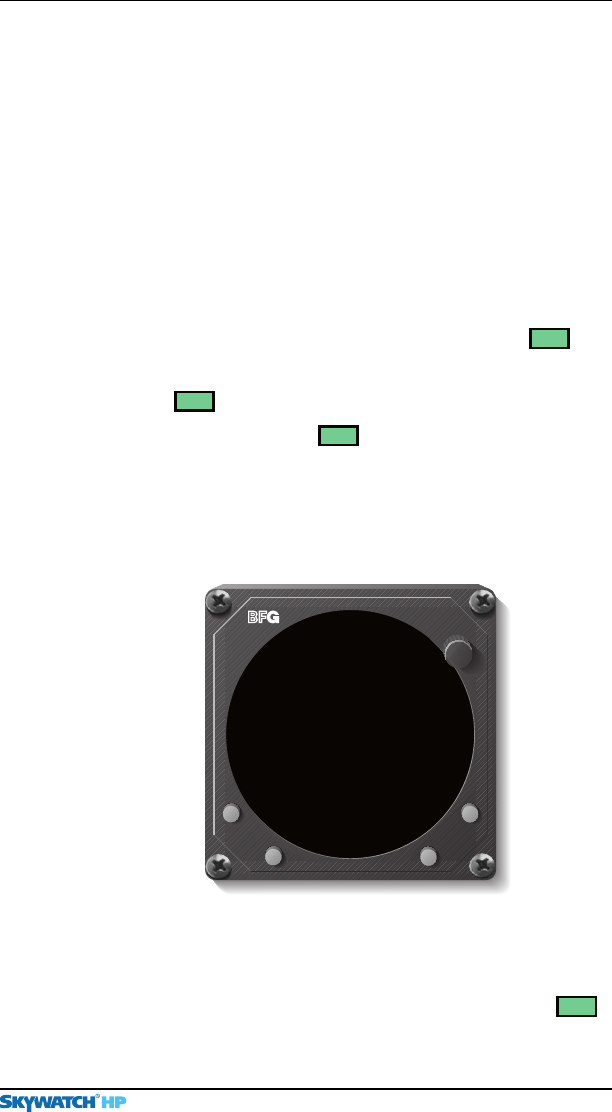
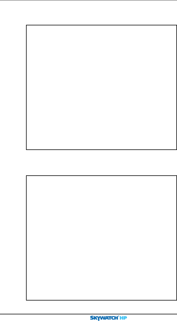
Figure 3-8. Message Screen With Two Messages
EXIT
InvalidHeading
BRT
OFF
Position InvalidGPS
Degraded Items:
SKY899 MESSAGES
Respond to a Degraded System
2. Write down the faults then press the
EXIT
button to return to
the previous screen.
Once you’ve read the Degraded Operation screen, the
MSG
indicator on the traffic screen or standby screen changes to
Chapter 3 – Operating Instructions
SKY899 Pilot’s Guide
3-10
Preliminary
Respond to a Degraded System
MSG
(with no highlighting box). With
MSG
displayed, you
can press the adjacent button to see the message screen
again. Once the faults responsible for the degraded condi-
tion are corrected, the
MSG
symbol disappears from the
traffic screen, but remains on the Standby screen. Pressing
the message button in this case on the Standby screen
displays the message screen with no messages (figure 3-9).
3. Contact your authorized
BFG
oodrich
A
vionics
S
ystems dealer
for troubleshooting help. Be sure to tell the troubleshooting
personnel about the faults that you wrote down in step
2
.
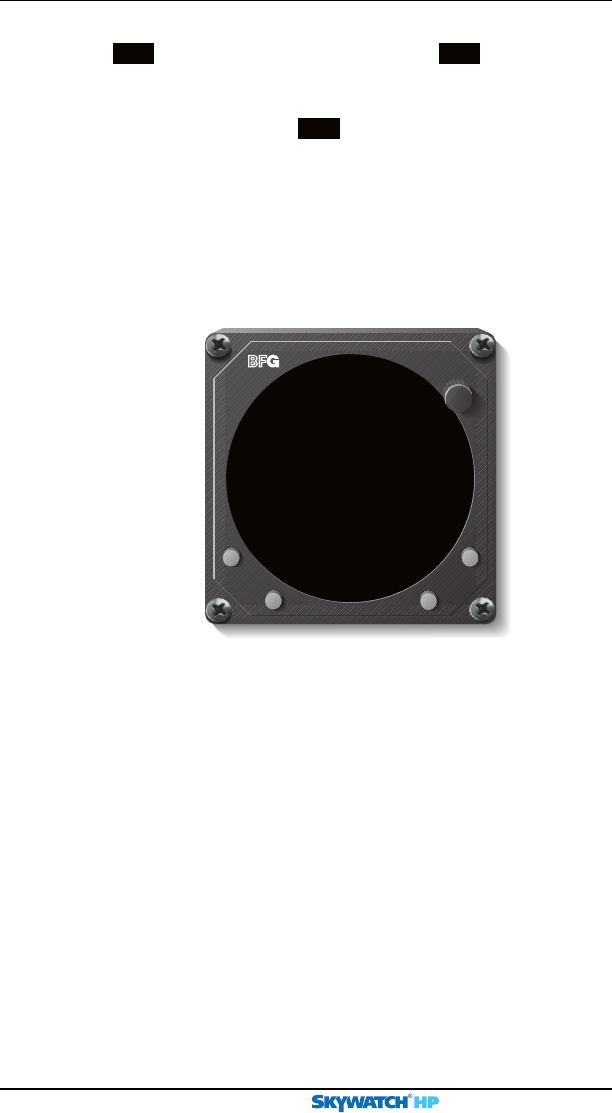
Figure 3-9. Message Screen With No Messages
EXIT
BRT
OFF
MessagesNo
SKY899 MESSAGES

SKY899 Pilot’s Guide 4-1
Preliminary
Principles of
Operation
Chapter 4
Introduction
This chapter describes, lists, and illustrates Traffic Advisory
(TA) criteria and other factors that affect the display of traffic
symbols including Automatic Dependent Surveillance Broadcast
(ADS-B). Table 4-1 on the next page summarizes the criteria
necessary for the SKY899 to display a TA.
Sensitivity Levels
The SKY899 uses one of two sensitivity levels, A or B, to
determine when to display a TA. Having two sensitivity levels
allows the SKY899 to reduce the number of nuisance TAs
during takeoff and landing (sensitivity level A), and to maxi-
mize the detection of TAs during the cruise phase of your flight
(sensitivity level B).
Sensitivity Level A
Sensitivity level A consists of two criteria for displaying a TA:
1. The intruder aircraft enters into a cylinder of airspace
surrounding your aircraft defined by a 0.2 nmi horizon-
tal radius and a height of ±600 ft from your aircraft. (See
figures 4-1 through 4-3.)
OR…
2. The intruder aircraft approaches your aircraft on a
course that will intercept your aircraft within 15 or 20
seconds (within 15 seconds for a non-altitude reporting
intruder aircraft; within 20 seconds for an altitude
reporting intruder aircraft).
Chapter 4 – Principles of Operation
SKY899 Pilot’s Guide
4-2
Preliminary
TA Criteria
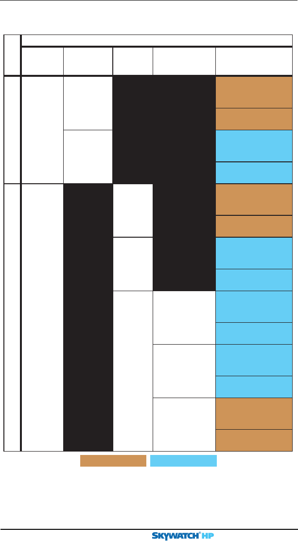
Table 4-1. Fourteen Situations in Which a Traffic Advisory Will Occur
* Having a radio altimeter means having a compatible radio altimeter wired to the SKY899 and
providing valid altitude information.
** CPA means Closest Point of Approach.
*** Ground speed is not available whenever your GPS navigation information is not available.
Sensitivity Level A Sensitivity Level B
The SKY899 Will Issue a Traffic Advisory…
No.
If Your
Aircraft…
And Your
Aircraft’s
Altitude Is…
And Your
Landing
Gear Is…
And Your
Ground Speed
Is…
And An Intruder
Aircraft Is
Detected…
1 has a radio
altimeter*
below 2000 ft
AGL
within a 0.2 nmi
horizontal radius and a
±600 ft relative altitude
2within 15–20 sec.
of
CPA**
3 above 2000 ft
AGL
within a 0.55 nmi
horizontal radius and a
±800 ft relative altitude
4within 20–30 sec.
of
CPA**
5 does not
have a radio
altimeter*
down within a 0.2 nmi
horizontal radius and a
±600 ft relative altitude
6within 15–20 sec.
of
CPA**
7up within a 0.55 nmi
horizontal radius and a
±800 ft relative altitude
8within 20–30 sec.
of
CPA**
9fixed not available*** within a 0.55 nmi
horizontal radius and a
±800 ft relative altitude
10 within 20–30 sec.
of
CPA**
11 available and
greater than or
equal to 120 knots
within a 0.55 nmi
horizontal radius and a
±800 ft relative altitude
12 within 20–30 sec.
of
CPA**
13 available and less
than 120 knots
within a 0.2 nmi
horizontal radius and a
±600 ft relative altitude
14 within 15–20 sec.
of
CPA**

Chapter 4 – Principles of Operation
SKY899 Pilot’s Guide 4-3
Preliminary
The SKY899 uses sensitivity level A in the following situations
(corresponds to numbers 1, 2, 5, 6, 13, and 14 in table 4-1):
1. Your aircraft has a radio altimeter and is below 2,000 ft
AGL.
2. Your aircraft has no radio altimeter but its retractable
landing gear is down.
3. Your aircraft has no radio altimeter, a fixed landing gear,
and your ground speed is available and is less than 120
knots.
Sensitivity Level B
Sensitivity level B consists of two criteria for displaying a TA:
1. The intruder aircraft enters into a cylinder of airspace
surrounding your aircraft defined by a 0.55 nmi hori-
zontal radius and a height of ±800 ft from your aircraft.
(See figures 4-1 through 4-3.)
OR…
2. The intruder aircraft approaches your aircraft on a
course that will intercept your aircraft within 20 or 30
seconds (within 20 seconds for a non-altitude reporting
intruder aircraft; within 30 seconds for an altitude
reporting intruder aircraft).
The SKY899 uses sensitivity level B in the following situations
(corresponds to numbers 3, 4, 7, 8, 9, 10, 11, and 12 in table 4-1):
1. Your aircraft has a radio altimeter and is above 2,000 ft
AGL.
2. Your aircraft has no radio altimeter but its retractable
landing gear is up.
3. Your aircraft has no radio altimeter, a fixed landing gear,
and your ground speed is not available.
4. Your aircraft has no radio altimeter, a fixed landing gear,
and your ground speed is available but is greater than or
equal to 120 knots.
Sensitivity Levels
Chapter 4 – Principles of Operation
SKY899 Pilot’s Guide
4-4
Preliminary
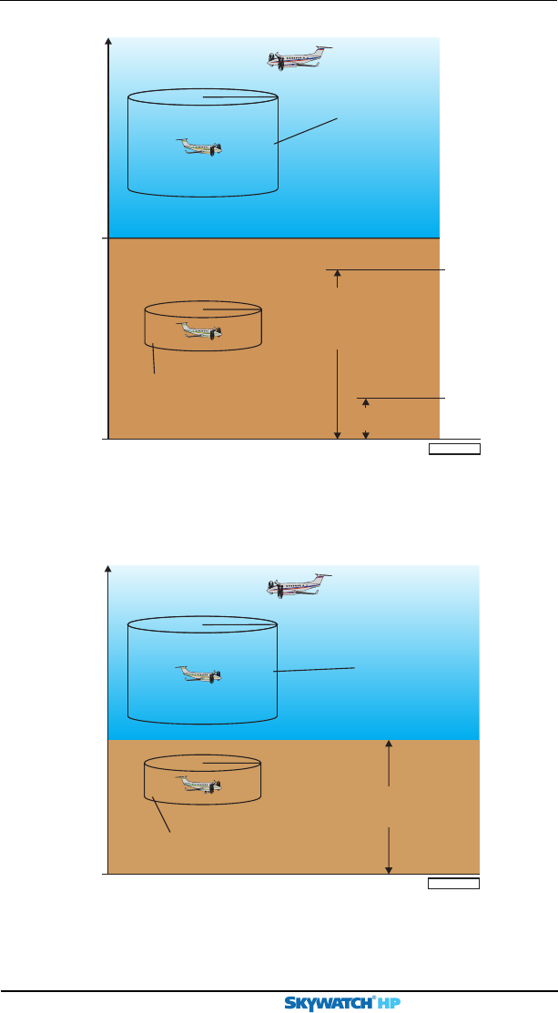
TA Zones
0.2 nmi
+600 ft
–600 ft
Thisareaor 20seconds*
0.55 nmi
+800 ft
–800 ft
Thisareaor 30 seconds*
*
**15 seconds for non-altitude reporting intruder aircraft
*20 seconds for non-altitude reporting intruder aircraft Not to scale
Intruder aircraft
GL
If own
aircraft
is below
1,700
feet
If own
aircraft
is below
400
feet
2,000
feet
Ground
intruders
below
380 ft
filtered
TA zone when
own aircraft is
below 2,000 ft
(sensitivity level A)
TA zone when
own aircraft is
above 2,000 ft
(sensitivity level B)
SKY899
audio inhibited
Figure 4-2. TA Zones If Your Aircraft Has No Radio Altimeter, But Does Have
a Retractable Landing Gear
Figure 4-1. TA Zones If Your Aircraft Has a Radio Altimeter
0.2 nmi
+600 ft
–600 ft
Thisareaor 20seconds*
0.55 nmi
+800 ft
–800 ft
Thisareaor 30 seconds*
*
**15 seconds for non-altitude reporting intruder aircraft
*20 seconds for non-altitude reporting intruder aircraft Not to scale
Intruder aircraft
GL
TA zone
when landing gear is up
(sensitivity level B)
TA zone
when landing gear is down
(sensitivity level A)
SKY899 audio
inhibited when landing
gear is down
Chapter 4 – Principles of Operation
SKY899 Pilot’s Guide 4-5
Preliminary
Audio Inhibit, SKY899
This audio inhibit feature prevents the aural part of TAs,
“traffic traffic,” from being announced during takeoff and
landing in order to minimize pilot distraction. The correspond-
ing TA symbols are still displayed.
The SKY899 uses this audio inhibit feature in the following
situations:
1. Your aircraft has a radio altimeter and you’re below 400
ft AGL. (See figure 4-1.)
2. Your aircraft has no radio altimeter but its retractable
landing gear is down. (See figure 4-2.) (Audio is not
inhibited if you have fixed landing gear and no radio
altimeter.)
Audio Inhibit, GPWS, EGPWS, or TAWS
If your aircraft has a Ground Proximity Warning System
(GPWS), Enhanced GPWS (EGPWS), or Terrain Awareness and
Warning System (TAWS) interfaced with the SKY899 and an
alarm from one of those systems occurs, the SKY899 senses the
alarm and delays the aural “traffic, traffic” component of any
TAs issued until the alarm clears.
Audio Inhibit
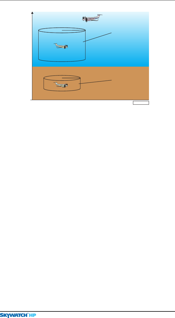
Figure 4-3. TA Zones If Your Aircraft Has No Radio Altimeter
and a Fixed Landing Gear
0.2 nmi
+600 ft
–600 ft
Thisareaor 20seconds*
0.55 nmi
+800 ft
–800 ft
Thisareaor 30 seconds*
*
**15 seconds for non-altitude reporting intruder aircraft
*20 seconds for non-altitude reporting intruder aircraft Not to scale
Intruder aircraft
GL
TA zone
when your ground
speed is unavailable,
or when your ground
speed is available,
but is greater than or
equal to 120 knots
(sensitivity level B)
TA zone
when your ground speed
is available and is
less than 120 knots
(sensitivity level A)
Chapter 4 – Principles of Operation
SKY899 Pilot’s Guide
4-6
Preliminary
TA Symbol Duration
A TA symbol remains on the screen for at least 8 seconds, even
if the intruder aircraft no longer meets the TA criteria, as long
as the SKY899 continues to track the aircraft.
Ground Intruder Filtering
Ground intruder filtering reduces the clutter of visual symbols
and aural announcements that would otherwise be generated
for intruder aircraft typically present on or near the ground
near airports.
For intruder aircraft determined to be below 380 ft AGL,
ground intruder filtering prevents the issuing of TAs and PAs,
and prevents the display of OT symbols. (See figure 4-1.)
The SKY899 uses ground intruder filtering only if your aircraft
has a radio altimeter and you’re below 1,700 ft AGL.
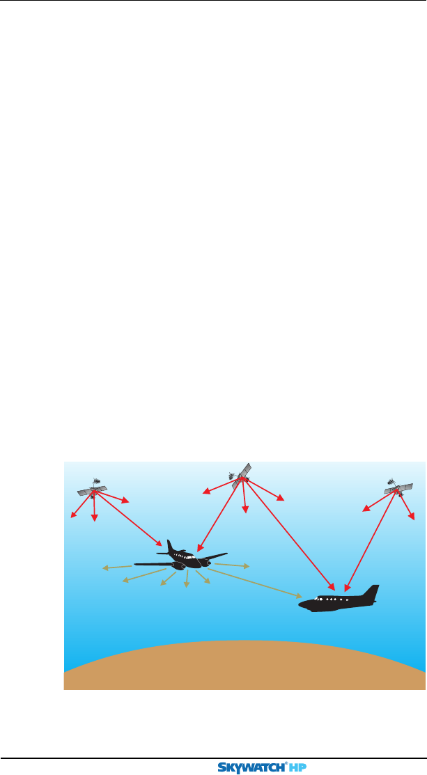
ADS-B
Unlike the current ATC system of ground-based Secondary
Surveillance Radar (SSR) interrogations and aircraft transponder
replies, the ADS-B-based Free Flight Air Traffic Management
(ATM) system of the future will depend more on aircraft-to-
aircraft exchange of aircraft state information (figure 4-4).
Ground Intruder Filtering
Figure 4-4. ADS-B
Intruder
aircraft
Own aircraft
GPS satellite
GPS satellite
ADS-B
squitter
message
GPS satellite

Chapter 4 – Principles of Operation
SKY899 Pilot’s Guide 4-7
Preliminary
ADS-B
The SKY899 anticipates the future Free Flight environment by
continuously monitoring the dedicated data link frequency
(1090 MHz) for ADS-B mode S extended squitter messages
within 50 nmi. These messages are broadcast, without interro-
gation, from aircraft with ADS-B-capable mode S transponders.
The SKY899 does not require a mode S transponder, ADS-B-
capable or otherwise, to perform its ADS-B surveillance.
An ADS-B message contains nav data for the intruder aircraft
including GPS position, ident, ground speed, and intent. The
SKY899 uses this nav data along with its own aircraft GPS nav
data to calculate the relative position of the intruder to enhance
its active ATCRBS surveillance of the intruder.
SKY899 Pilot’s Guide 5-1
Preliminary
Display
Interpretation
Chapter 5
Introduction
This chapter explains the meaning of several sample screens.
The abbreviation CPA used in some of the figures means closest
point of approach.
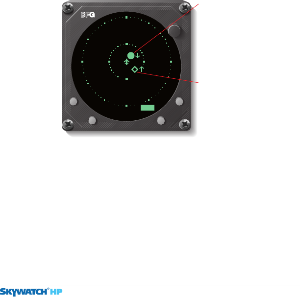
Figure 5-1. TA & OT on 15 nmi Range, UNR Mode
BRT
OFF
UNR 15nm
-07
+03
Traffic Advisory
Intruder aircraft at
1o’clock, 2 nmi
away, 300 ft above
you, descending at
a rate greater than
500 fpm. CPA within
20 to 30 seconds.
Other Traffic
Intruder aircraft at
4:30, 4 nmi away,
700 ft below you,
ascending at a rate
greater than 500 fpm.
No immediate threat.
Displays as a PA
(solid diamond) on
TCAS installations.
Chapter 5 – Display Interpretation
SKY899 Pilot’s Guide
5-2
Preliminary
Displays
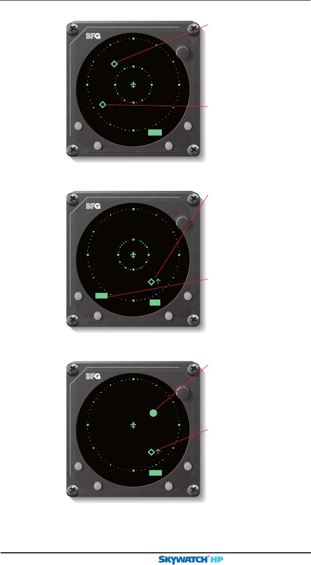
Figure 5-2. Other Traffic on 15 nmi Range, UNR Mode
Figure 5-3. Other Traffic on 6 nmi Range, NRM Mode
Figure 5-4. TA & OT on 2 nmi Range, BLW Mode
BRT
OFF
Traffic Advisory
Non-altitude-reporting
intruder aircraft at
2o’clock, 1 nmi
away. CPA within
15 to 20 seconds.
Other Traffic
Intruder aircraft at
5o’clock, 1.5 nmi
away, 1,000 ft above
you, ascending at a
rate greater than
500 fpm. No
immediate threat.
Displays as a PA
(solid diamond) on
TCAS installations.
BLW
2nm
+10
MSG
BRT
OFF
UNR 15nm
Other Traffic
Non-altitude-reporting
intruder aircraft at
10:30, 9 nmi away.
No immediate threat.
Other Traffic
Intruder aircraft at
8o’clock, 11 nmi
away, 9,900 ft below
you in level flight. No
immediate threat.
-99
BRT
OFF
NRM 6nm
00
MSG
New Messages
Indicates one or more
new messages are
waiting to be read.
Other Traffic
Intruder aircraft at
5o’clock, 4.5 nmi
away, at your altitude,
ascending at a rate
greater than 500 fpm.
No immediate threat.
Chapter 5 – Display Interpretation
SKY899 Pilot’s Guide 5-3
Preliminary
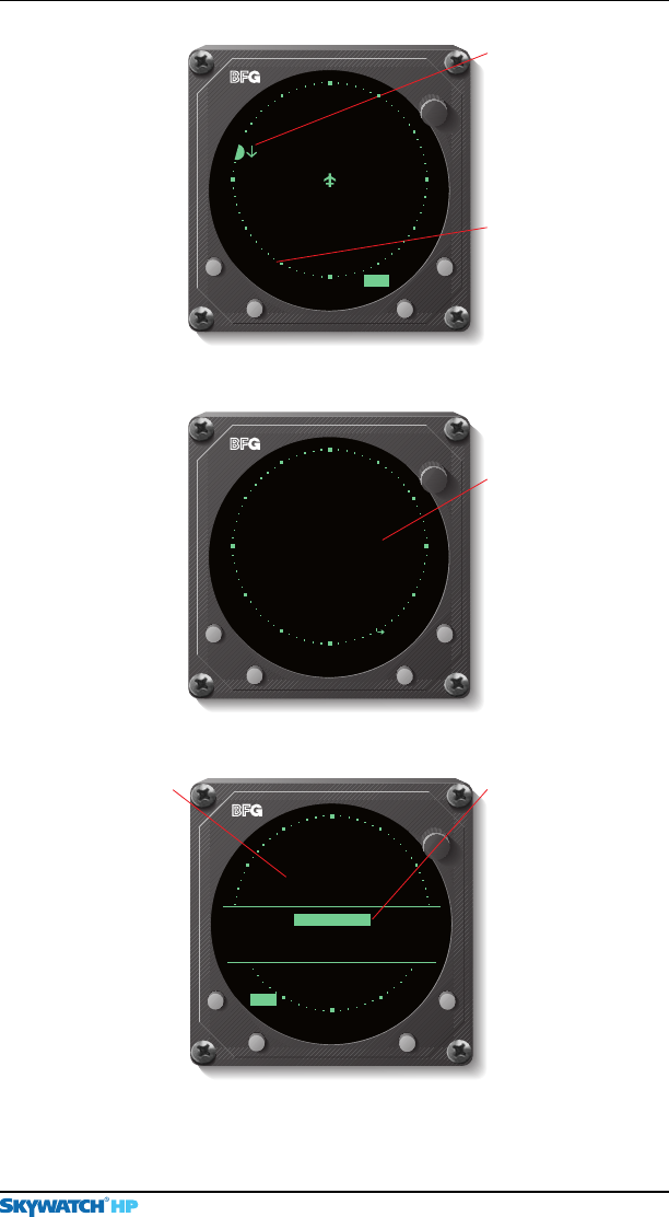
Figure 5-5. Off-Screen TA on 2 nmi Range, ABV Mode
Figure 5-6. Standby Screen
BRT
OFF
Off-Screen TA
Intruder aircraft at
9:30, more than
2 nmi away. 500 ft
above you, descending
at a rate greater than
500 fpm. CPA within
20 to 30 seconds.
Old Messages
Indicates there are
one or more old
messages that are
still valid, but no new
messages.
ABV
2nm
MSG
+05
BRT
OFF
Standby
When in standby, the
SKY899 does not
transmit interrogations
or track intruder
aircraft. Press the
button labeled OPR
to begin tracking
intruder aircraft.
>
OPR
Standby
SKY899
TEST
MSG
6nm
Figure 5-7. Failed Screen
BRT
OFF
Failed
SKY899
Error 20
TEST
Barometric Input Error
Error 20
Indicates that the
barometric input is
missing or invalid.
Once the valid baro-
metric input returns,
this screen goes
away and normal
operation resumes.
SKY899 Failed
Occurs any time the
SKY899 detects an
error that prohibits
further operation of
the SKY899 in
SKYWATCH mode
as long as the
message remains
on the screen.
MSG
Displays

SKY899 Pilot’s Guide 6-1
Preliminary
Specifications
Chapter 6
Table 6-1. TRC899 Specifications*
Part Number Definition:
805-11900-001
Size:
Not including mounting tray:
7.62 in (19.36 cm) high
3.56 in (9.04 cm) wide
12.52 in (31.90 cm) deep
Weight:
Not including mounting tray:
8.75 lb (3.97 kg)
Including standard mounting tray:
9.63 lb (4.37 kg)
Including ruggedized mounting tray:
10.76 lb (4.88 kg)
Tracking Capability:
Up to 35 intruder aircraft (displays only the 8 highest priority aircraft)
Surveillance Range:
Horizontal tracking radius:
35 nmi maximum for ATCRBS surveillance
50 nmi maximum for ADS-B surveillance
Relative altitude tracking range:
±10,000 ft maximum
Display Ranges:
Horizontal display ranges:
2, 6, and 15 nmi
Vertical display modes:
±2,700 ft (normal mode)
+9,000 ft to -2,700 ft (above mode/look up)
+2,700 ft to -9,000 ft (below mode/look down)
±9,900 ft (unrestricted mode)
*Specifications subject to change without notice.
(Continues on next page)

Chapter 6 – Specifications
SKY899 Pilot’s Guide
6-2
Preliminary
TRC Specs (Continued)
Table 6-1. TRC899 Specifications* (Continued)
Range Accuracy:
0.05 nmi typical
Bearing Accuracy:
5° RMS typical with NY156 antenna
7° RMS typical with NY164 antenna
Altitude Accuracy:
±200 ft
Maximum Closure Rate:
1200 knots
Power Input Requirements:
18 to 32 V dc, 2 A maximum at +28 V dc
Transmitter Power Output:
Peak 1030 MHz RF output power of 52 dBm (158.5 W) ±1dB
Operating Temperature:
-55 to +70 °C (-67 to +158 °F)
Storage Temperature:
-55 to +85 °C (-67 to +185 °F)
Operating Altitude:
55,000 ft maximum
Cooling:
Conduction and forced air convection (internal fan)
Certification Compliance:
U.S. FAA TSO C147 and C118. Contact BFG for the latest foreign
country certifications. Refer to the latest revision of FSAW 98-04
for Flight Standards Service (AFS) policy concerning follow-on field
approvals.
RTCA Compliance:
Environmental:
DO-160D Category
(F2X)BAB(S[2BM]U[2G])XXXXXXZBABA(RR)L(XXXX)XXA
Software:
DO-178B Level D
*Specifications subject to change without notice.

Chapter 6 – Specifications
SKY899 Pilot’s Guide 6-3
Preliminary
y
BFG Display Specs
Table 6-2. BFG WX-1000/SKY497 Display Specifications*
Part Number Definition:
78-8060-5900-8 – Black Bezel
78-8060-5900-9 – Gray Bezel
Size:
3.37 in (8.56 cm) high
3.37 in (8.56 cm) wide
8.24 in (20.92 cm) deep
Weight:
2.3 lb (1.0 kg)
Power Input Requirements:
+15/-15 V dc, 0.7 A maximum (provided by the TRC899)
Operating Temperature:
-20 to +55 °C (-4 to +131 °F)
Storage Temperature:
-55 to +70 °C (-67 to +158 °F)
Operating Altitude:
55,000 ft maximum
TSO Compliance:
C110a and C113
RTCA Compliance:
DO-160C F1-CA(NBM)XXXXXXZXXXZUAXXXXXX
*Specifications subject to change without notice.
Chapter 6 – Specifications
SKY899 Pilot’s Guide
6-4
Preliminary
Table 6-3. NY164 Directional Antenna Specifications
(for TAS installations only)*
Part Number:
805-10890-001
Size:
1.30 in (3.25 cm) high
6.23 in (15.82 cm) wide
11.12 in (28.24 cm) deep
Weight:
2.3 lb (1.04 kg)
Speed:
Rated to 600 knots (0.9 Mach) @ 25,000 ft
Frequency:
1,030-1,090 MHz
TSO Category:
C118
Environmental Category:
DO-160C F2-AC(CLM)XSFDFSXXXXXXXL(2A)X
Finish:
Gloss white Skydrol resistant polyurethane paint
*Specifications subject to change without notice.
Antenna Specs
Part Number:
805-10003-001
Size:
1.30 in (3.25 cm) high
6.25 in (15.88 cm) wide
11.12 in (28.24 cm) deep
Weight:
2.3 lb (1.04 kg)
Speed:
Rated to 600 knots (0.9 Mach) @ 25,000 ft
Frequency:
1,030-1,090 MHz
TSO Category:
C118
Environmental Category:
DO-160C F2-AC(CLM)XSFDFSXXXXXXXL(2A)X
Finish:
Gloss white Skydrol resistant polyurethane paint
*Specifications subject to change without notice.
Table 6-4. NY156 Directional Antenna Specifications
(required for TCAS I installations, optional for TAS)*

SKY899 Pilot’s Guide 7-1
Preliminary
Warranty
Information
Chapter 7
Introduction
The
SKY899
is warranted for
2
years from the date of instal-
lation (not to exceed
30
months from the date of shipment
from
BFG
oodrich
A
vionics
S
ystems,
I
nc.) subject to the
following limitations.
Warranty Statement
BFG
oodrich
A
vionics
S
ystems,
I
nc. (hereinafter called
BFGAS
)
warrants each item of new equipment manufactured or sold
by
BFGAS
to be free from defects in material and workman-
ship, under normal use as intended, for a period of
30
months from date of shipment by
BFGAS
to an authorized
facility, or
24
months from date of installation by an autho-
rized facility, whichever occurs first. No claim for breach of
warranties will be allowed unless
BFGAS
is notified thereof, in
writing, within thirty (
30
) days after the material or work-
manship defect is found.
The obligation of
BFGAS
shall be limited to replacing or
repairing at its factory the equipment found defective under
terms of this warranty certificate; providing that such equip-
ment is returned in an approved shipping container, trans-
portation charges prepaid, to
BFGAS
,
G
rand
R
apids,
M
ichi-
gan, or such other location as
BFGAS
may authorize.
BFGAS
reserves the right to have necessary repairs performed by an
authorized agency.

Chapter 7 – Warranty Information
SKY899 Pilot’s Guide
7-2
Preliminary
Related Policies
This warranty shall not apply to any unit or part thereof which
has not been installed or maintained in accordance with BFGAS
instructions, or has been repaired or altered in any way so as to
adversely affect its performance or reliability, or which has been
subjected to misuse, negligence or accident.
This warranty is exclusive and is accepted by buyer in lieu of all
other guaranties or warranties express or implied, including
without limitation the implied warranties of merchantability and
fitness for a particular purpose. Buyer agrees that in no event will
BFGAS
liability for all losses from any cause, whether based in
contract, negligence, strict liability, other tort or otherwise,
exceed buyer’s net purchase price, nor will
BFGAS
be liable for
any special, incidental, consequential, or exemplary damages.
BFGAS reserves the right to make changes in design or addi-
tions to or improvements in its equipment without the obliga-
tion to install such additions or improvement in equipment
theretofore manufactured.
A Subsidiary of The BFGoodrich Company
Related Policies and Procedures
a. If the original registered owner of a SKY899 sells the
aircraft in which the SKY899 is installed during the
warranty period, the remaining warranty may be
transferred. Written notification of the transaction must
be submitted by the initial recipient of the warranty to:
ATTENTION: WARRANTY ADMINISTRATOR
BFGoodrich Avionics Systems, Inc.
5353 52nd Street, S.E.
Grand Rapids, MI 49512 USA
Telephone: (800)253-9525
b. Equipment must be installed by a BFG Avionics Systems,
Inc. authorized dealer or installer. Installation of
equipment by facilities not specifically authorized will
void the equipment warranty.
c. Notice of a claimed product defect must be given to
BFG Avionics Systems, Inc. or a designated BFG Avionics

Chapter 7 – Warranty Information
SKY899 Pilot’s Guide 7-3
Preliminary
Related Policies
Systems, Inc. service agency within the specified
warranty period.
d. A product which is defective in workmanship and/or
material shall be returned to BFG Avionics Systems, Inc.
via any authorized dealer with transportation charges
prepaid. After correction of such defects, the equipment
will be returned to the dealer, transportation prepaid by
BFG Avionics Systems, Inc. via surface transportation.
Any other means of transportation must be paid by the
customer.
The risk of loss or damage to all products in transit shall
be assumed by the party initiating the transportation of
such products. All items repaired or replaced hereunder
shall be warranted for the unexpired portion of the
original warranty.
e. BFG Avionics Systems, Inc. is in no way obligated or
responsible for supporting or participating in the costs
of the installation warranty. The entire responsibility
lies with the BFG Avionics Systems, Inc. authorized
dealer making the installation. BFG Avionics Systems,
Inc. is only responsible for the product warranties
outlined in the warranty statement.
f. BFG Avionics Systems, Inc. cannot authorize warranty
credit for troubleshooting of other systems in the aircraft
in order to reduce noise interference with the SKY899.

Preliminary
Record of Important Information
Dealer Information
Name _______________________________________________
Address _____________________________________________
City, State, Zip________________________________________
Telephone ___________________________________________
Equipment Information
Date of Purchase ______________________________________
Installation Date ______________________________________
TRC:
Model Number ____________________________________
Part Number ______________________________________
Serial Number _____________________________________
Mod Letter ________________________________________
Software Version ____________________________________
Antenna:
Model Number ____________________________________
Part Number ______________________________________
Serial Number _____________________________________
Mod Letter ________________________________________
Display:
Model Number ____________________________________
Part Number ______________________________________
Serial Number _____________________________________
Mod Letter ________________________________________
To ensure that a new or repaired SKY899 meets the TSO, meets
foreign government certification requirements, and meets BFG
performance standards, your SKY899 must be installed and tested
by a BFG-authorized SKY899 dealer.
NOTE

009-11901-001 (Rev. 91, 2/14/01)
BFGoodrich Avionics Systems, Inc.
5353 52nd Street, S.E.
Grand Rapids, MI 49512 USA
(800)253-9525 or (616)949-6600
www.bfgavionics.com
SKY899
Preliminary