L 3 Communications Avionics Systems TRC899 User Manual Chapter2
L-3 Communications, Avionics Systems Chapter2
UserManual.wiki
>
L 3 Communications Avionics Systems
>
TRC899 User Manual
>
User Manual 1 of 2
Contents
1.
User Manual 1 of 2
2.
User Manual 2 of 2
3.
Install Manual
User Manual 1 of 2
Navigation menu
Upload a User Manual
Namespaces
Wiki Guide
HTML
PDF
Info
Views
User Manual
Discussion / Help
Navigation


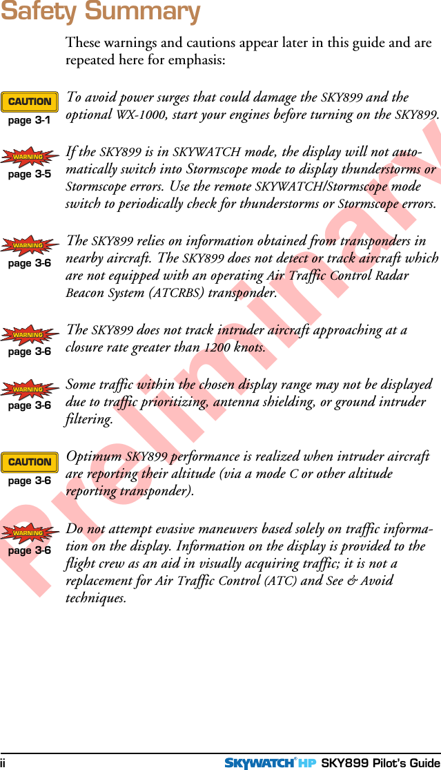

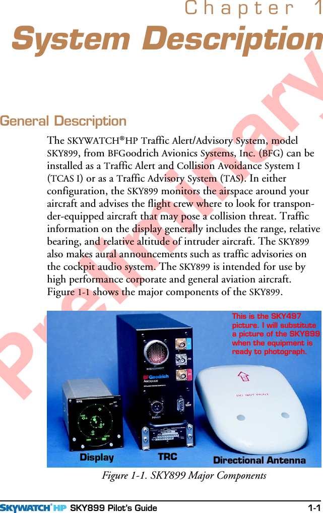
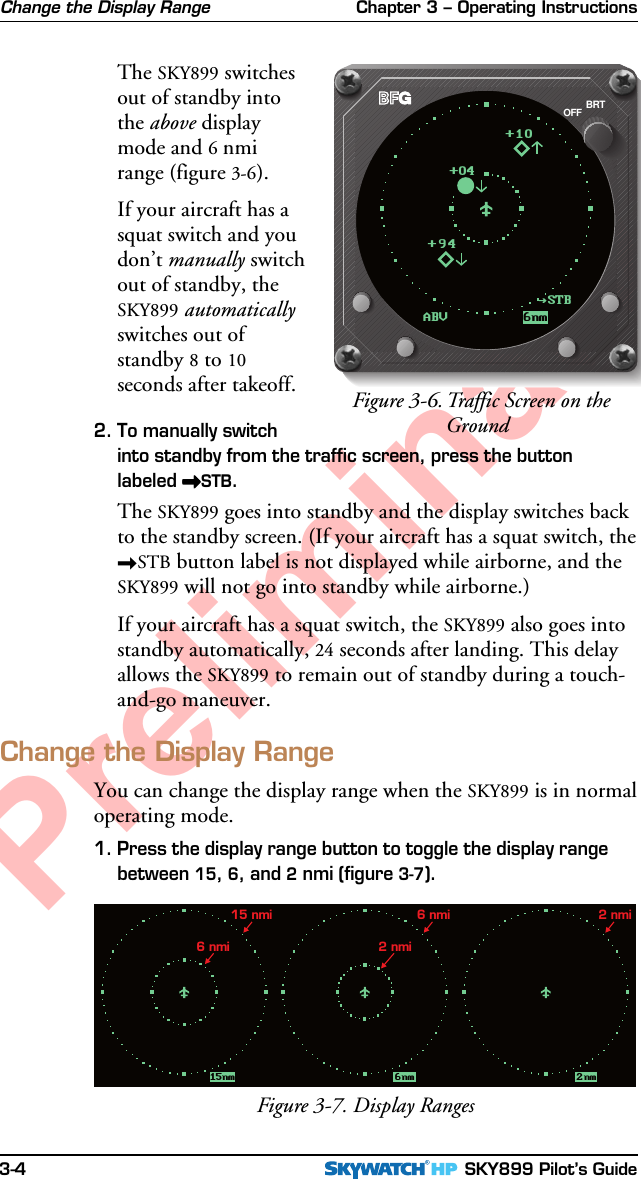
![Chapter 3 – Operating Instructions SKY899 Pilot’s Guide 3-3PreliminaryRun the Self TestRun the Operator-Initiated Self TestIt is recommended, but not required that you should run theoperator-initiated self test before the first flight of the day (or asspecified in your Aircraft Flight Manual [AFM]), and wheneveryou get a Failed screen.1. With the SKY899 in standby or failed mode, press the TESTbutton.The SKY899 begins itsself test and the testscreen (figure 3-5)appears. Uponsuccessful completionof the self test, youwill hear “SKY-WATCH System TestPassed” and thedisplay will revert tothe previous standbyor traffic screen.2. If you hear “SKY-WATCH System TestFailed” or see a SKY899 Failed screen, push the TEST buttonagain. If it fails again, refer to the Message Response sectionon page 3-7.3. If you hear “SKYWATCH System Test Passed” without seeingthe test screen, and the OFF/BRT knob is turned to BRT, turnoff the SKY899 and contact your authorized BFGoodrichAvionics Systems dealer for troubleshooting help.Switch Between Standby & Normal Operating ModeWhen you’re on the ground, you must manually switch out ofstandby if you want the SKY899 to display traffic information.The ability to switch out of standby on the ground in conjunc-tion with the above display mode is especially useful forscanning the airspace around the airport before takeoff.1. To manually switch into normal operating mode from thestandby screen (figure 3-2), press the button labeled >>>>>OPR.Figure 3-5. Test Screen6nmNRMSYSTEM TE STIN PROGRESS-10+10-02BRTOFF](https://usermanual.wiki/L-3-Communications-Avionics-Systems/TRC899.User-Manual-1-of-2/User-Guide-149251-Page-27.png)