L 3 Communications Avionics Systems TRC899 User Manual Install Manual
L-3 Communications, Avionics Systems Install Manual
UserManual.wiki
>
L 3 Communications Avionics Systems
>
TRC899 User Manual
>
Install Manual
Contents
1.
User Manual 1 of 2
2.
User Manual 2 of 2
3.
Install Manual
Install Manual
Navigation menu
Upload a User Manual
Namespaces
Wiki Guide
HTML
PDF
Info
Views
User Manual
Discussion / Help
Navigation
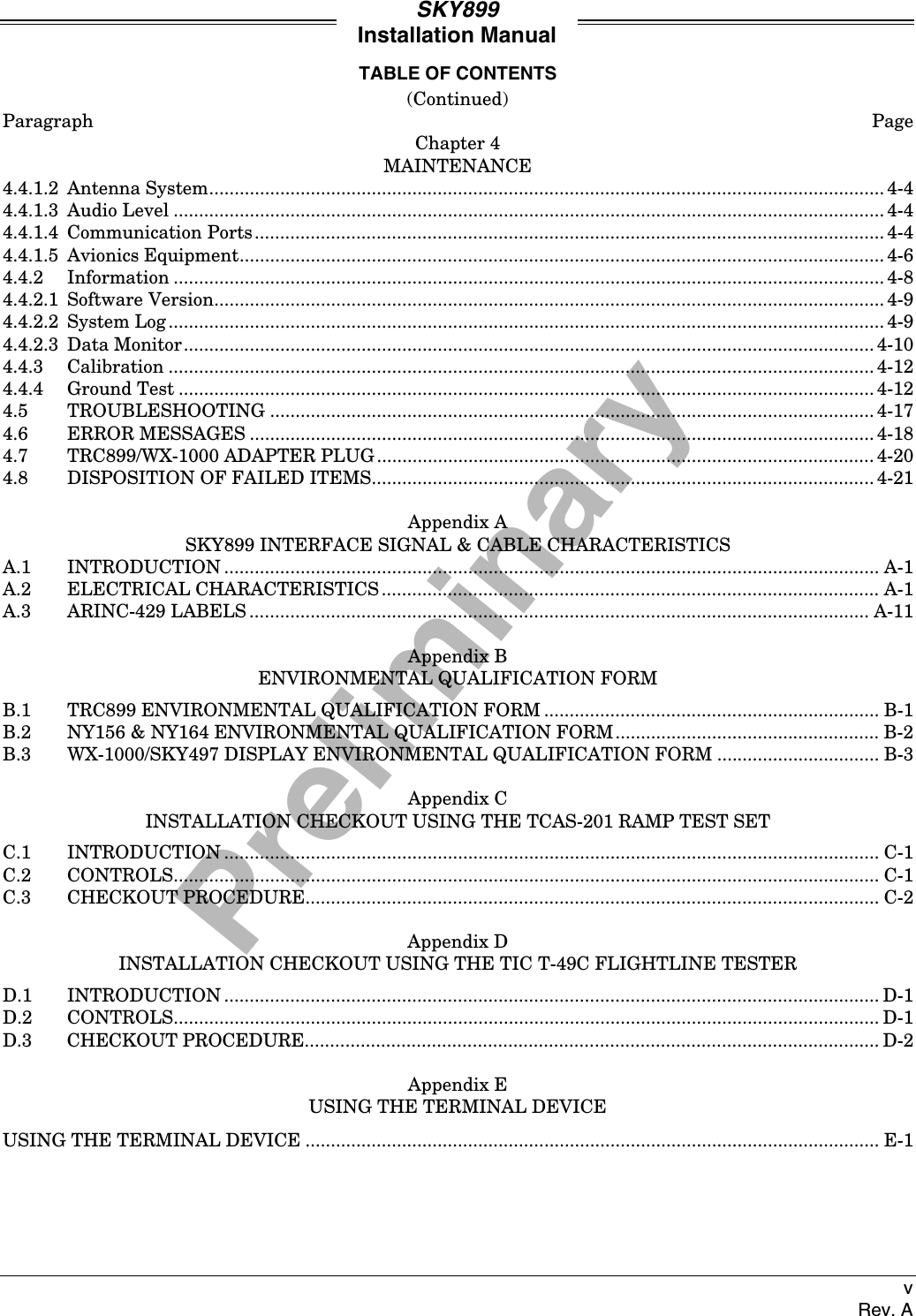

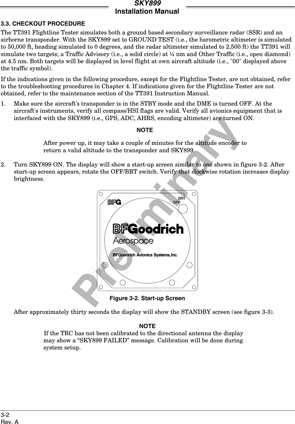
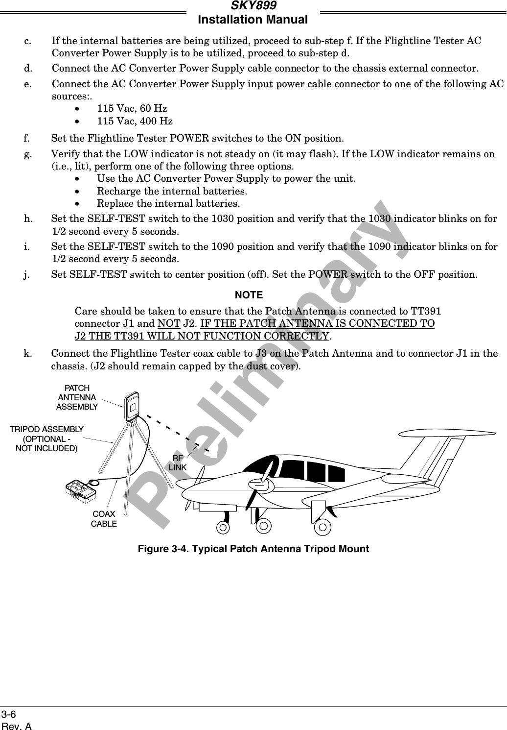
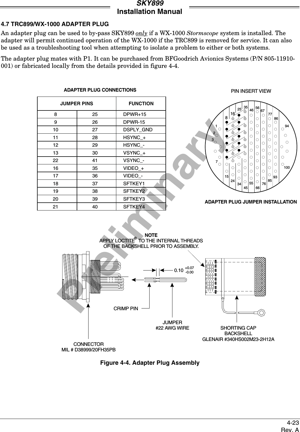
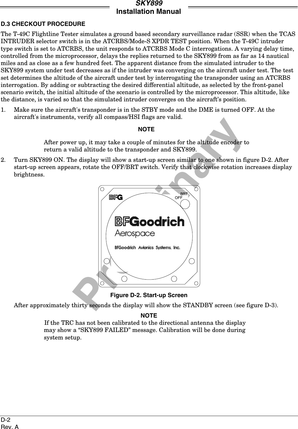
![PreliminarySKY899Installation Manual1-15Rev. A1.4 SPECIFICATIONS1.4.1 Transmitter Receiver Computer (TRC)PART NUMBER: 805-11900-001 - TRC899SIZE: Approximately 12.52 inches (31.90 cm) DeepApproximately 3.56 inches (9.04 cm) WideApproximately 7.62 inches (19.36 cm) HighWEIGHT: Approximately 8.88 lb (4.03 kg) Not Including Mounting TrayApproximately 9.76 lb (4.43 kg) With Standard Mounting TrayApproximately 10.89 lb (4.94 kg) With Ruggedized Mounting TrayOPERATING TEMPERATURE: -55 to +70 degrees Celsius (-67 to +158 degrees Fahrenheit)STORAGE TEMPERATURE: -55 to +85 degrees Celsius (-67 to +185 degrees Fahrenheit)OPERATING ALTITUDE: 55,000 feet (Maximum)COOLING: Conduction and Forced Air (Internal Fan) ConvectionPOWER REQUIREMENTS: 18 to 32 V dc, 2 Amps @ + 28 V dc(Maximum)TRACKING CAPABILITY: Up to 35 intruder aircraft (displays only the 8 highest priority aircraft)SURVEILLANCE RANGE: Horizontal tracking radius:35 nmi Maximum ATCRBS Surveillance50 nmi Maximum ADS-B SurveillanceRelative altitude tracking range:±10,000 ft maximumDISPLAY RANGES: Horizontal display ranges:2, 6 & 15 nmi (WX-1000/SKY497 Display)Relative altitude display ranges:±2,700 ft (normal mode)+9,000 ft to -2,700 ft (above mode/look up)+2,700 ft to -9,000 ft (below mode/look down)+9,900 ft to -9,900 ft (unrestricted)RANGE ACCURACY: ± 0.05 nmi (Typical)BEARING ACCURACY: With NY156 Antenna - 5° RMS (Typical) 30° Peak ErrorWith NY164 Antenna - 7° RMS (Typical) 30° Peak ErrorALTITUDE ACCURACY: ±200 ftCERTIFICATION: * USA (FAA) TSO C118 (TCAS I) & C147 (TAS) Refer to FSAW 98-04B for Flight StandardsService policy concerning follow-on field approvals.RTCA COMPLIANCE: Software DO178-B Level DDO-160D Category F2XBAB[(SBM)(UG)]XXXXXXZBABARRLXXXXXXA* Listed are current certifications at time of publication, contact Field Service Engineering at 1-800-453-0288 or 1-616-949-6600 for latest certification information.](https://usermanual.wiki/L-3-Communications-Avionics-Systems/TRC899.Install-Manual/User-Guide-149253-Page-25.png)

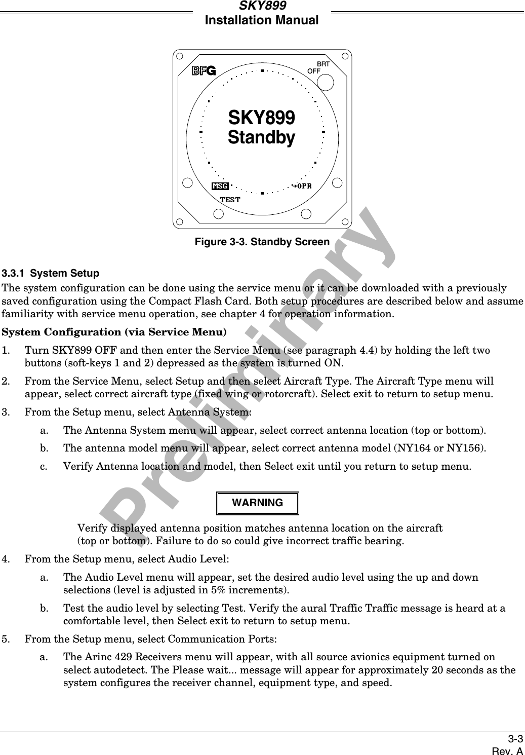
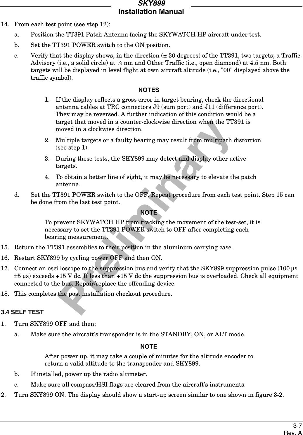
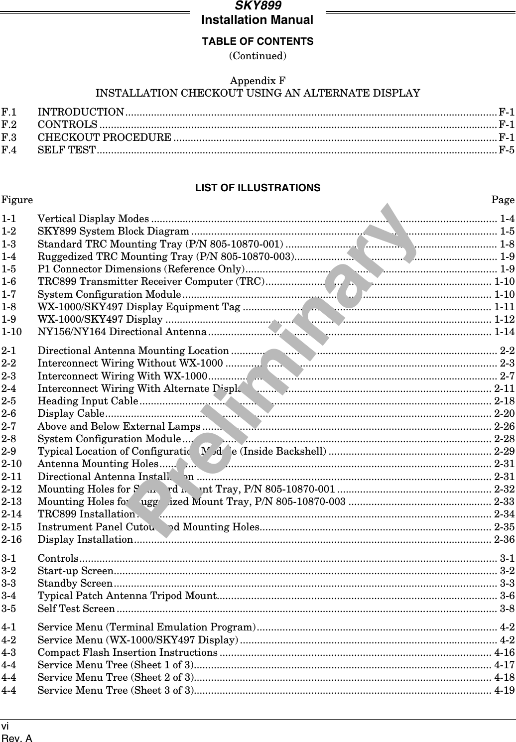
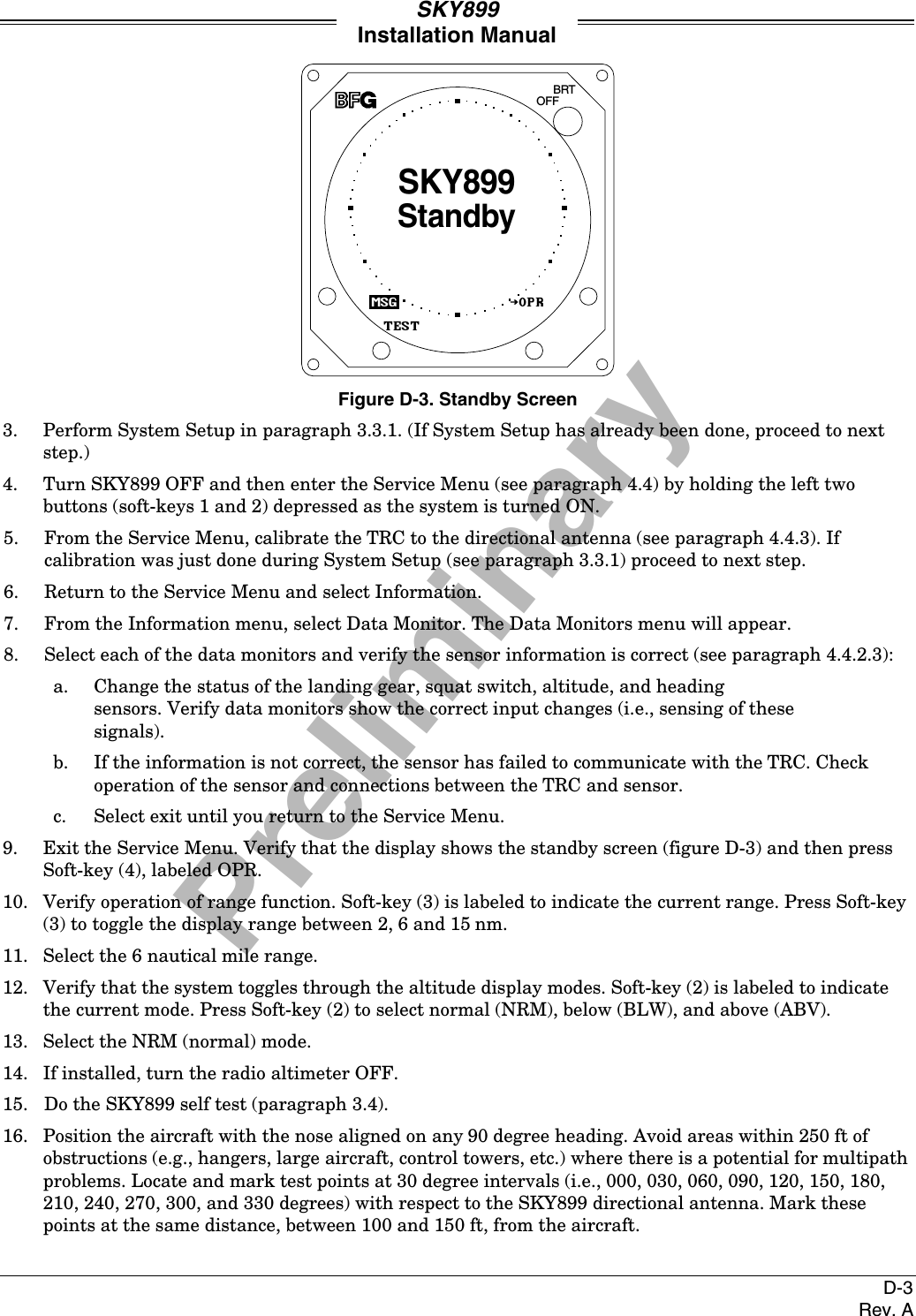
![PreliminarySKY899Installation Manual4-4Rev. AThe Aircraft Type menu provides the following choices:BRTOFFEXITNEXTSELPREVAircraft TypeFixed WingRotorcraft*None*4.4.1.2 Antenna SystemThe SKY899 allows you to install the antenna on top or bottom of aircraft and can use the NY156 (TCAS Iinstallation) or NY164 antenna. Only one antenna location can be selected, when choosing an antennalocation the other location will automatically be set to "None."The Antenna System menu provides the following choices:BRTOFFEXITNEXTSELPREVAntenna System*NY156 Directional*Bottom Antenna[None]Top AntennaSelecting Top Antenna (or Bottom Antenna) provides the following choices:BRTOFFEXITNEXTSELPREVTop AntennaNY164 Directional*NY156 Directional*None(Bottom Antenna menu is same as Top Antenna menu)](https://usermanual.wiki/L-3-Communications-Avionics-Systems/TRC899.Install-Manual/User-Guide-149253-Page-76.png)
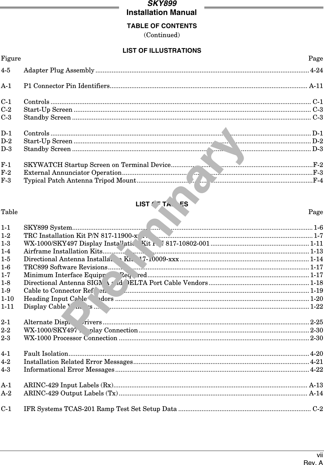
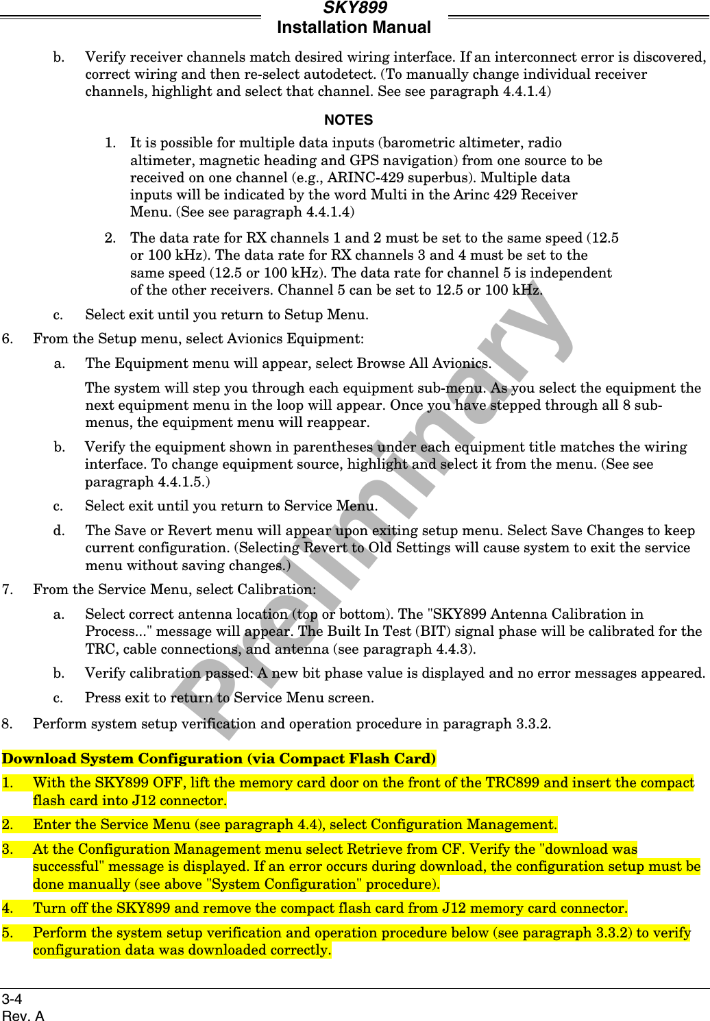
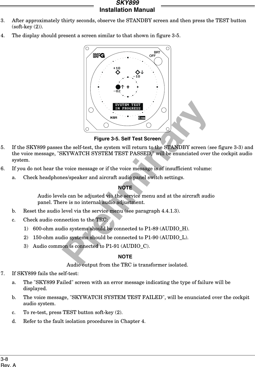
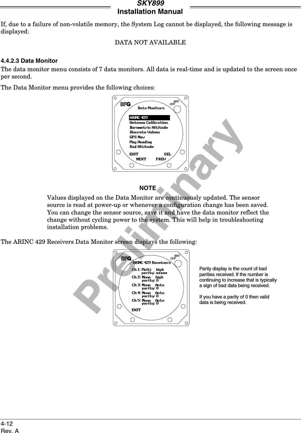
![PreliminarySKY899Installation Manual4-5Rev. A4.4.1.3 Audio LevelThe audio level menu allows you to set and test the audio level output. Audio level range is 0 to 40 mWinto 600 Ohm load, indicated by percentage (0-100%). Audio level can be adjusted up or down in 5%increments. Selecting test will cause the "traffic traffic" aural message to be annunciated over the aircraftaudio system.The Audio Level menu provides the following choices:BRTOFFEXITNEXTSELPREVAudio Level[50%]VolumeUpDownTest4.4.1.4 Communication PortsConfiguring the communication ports should be done before configuring the avionics equipment. SelectCommunication Ports from the Setup menu, the ARINC 429 receiver menu will be displayed. With allavionics equipment turned on, you can set the speed and the equipment type for each channelautomatically (Autodetect) or individually. Autodetect is recommended to configure the ARINC 429receiver's, however you can manually select the equipment type and speed for each individual channel.Selecting Communication Ports from the Setup menu will cause the ARINC 429 Receivers menu to appear:BRTOFFEXITNEXTSELPREVArinc 429 ReceiversCh. 1: Multi 100 kHzCh. 2: None 100 kHzAutodetectCh. 3: None AutoCh. 4: None AutoCh. 5: None AutoPlease wait... willbe displayed whileautodetect is beingperformedReceiver menu showsthe 5 RX channels, the429 source and thespeed. To changeindividual channel,highlight desired channeland press SEL.NOTES1. The data rate for RX channels 1 and 2 must be set to the same speed(12.5 or 100 kHz).2. The data rate for RX channels 3 and 4 must be set to the same speed(12.5 or 100 kHz).3. The data rate for channel 5 is independent of the other receivers.Channel 5 can be set to 12.5 or 100 kHz.](https://usermanual.wiki/L-3-Communications-Avionics-Systems/TRC899.Install-Manual/User-Guide-149253-Page-77.png)
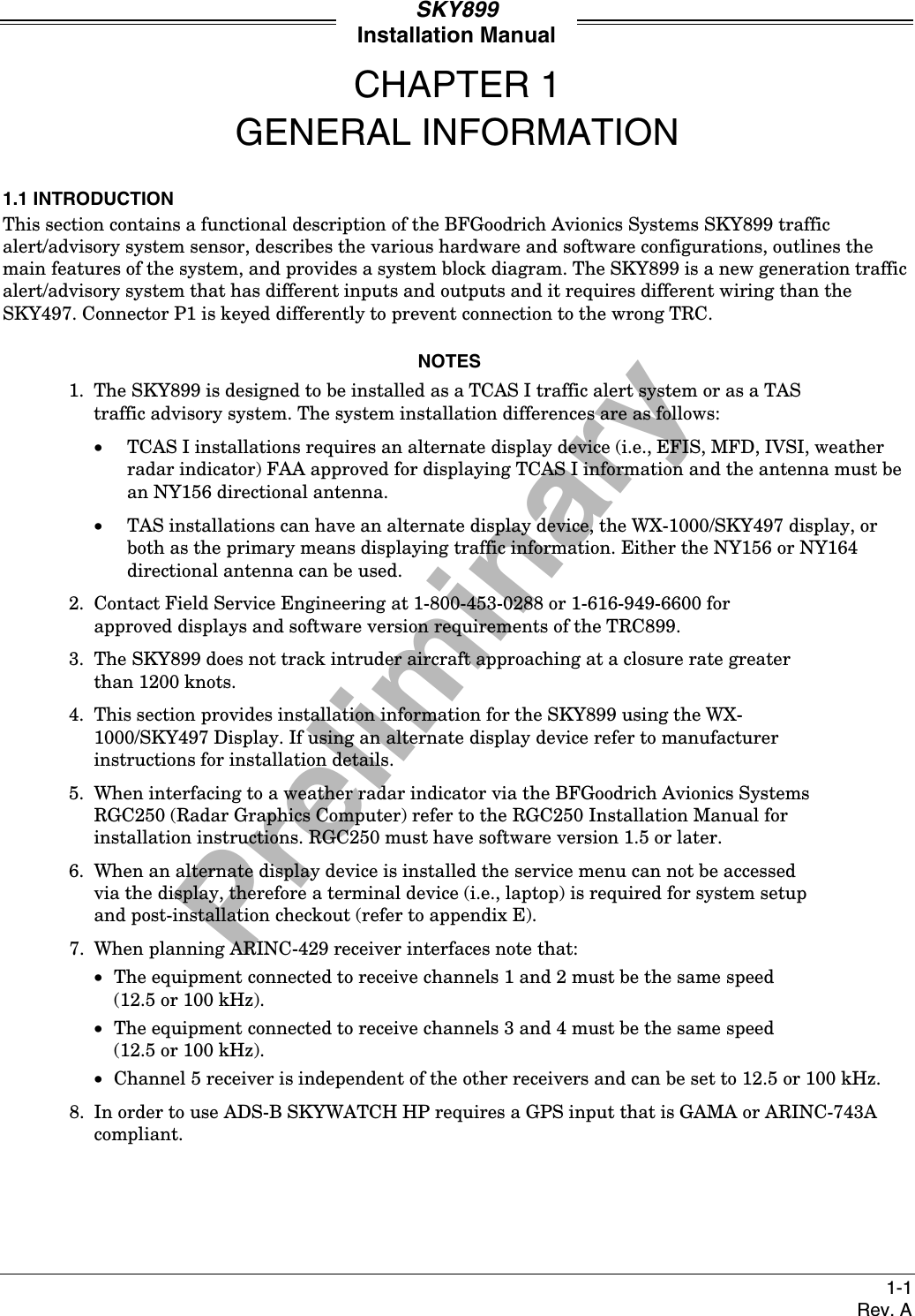
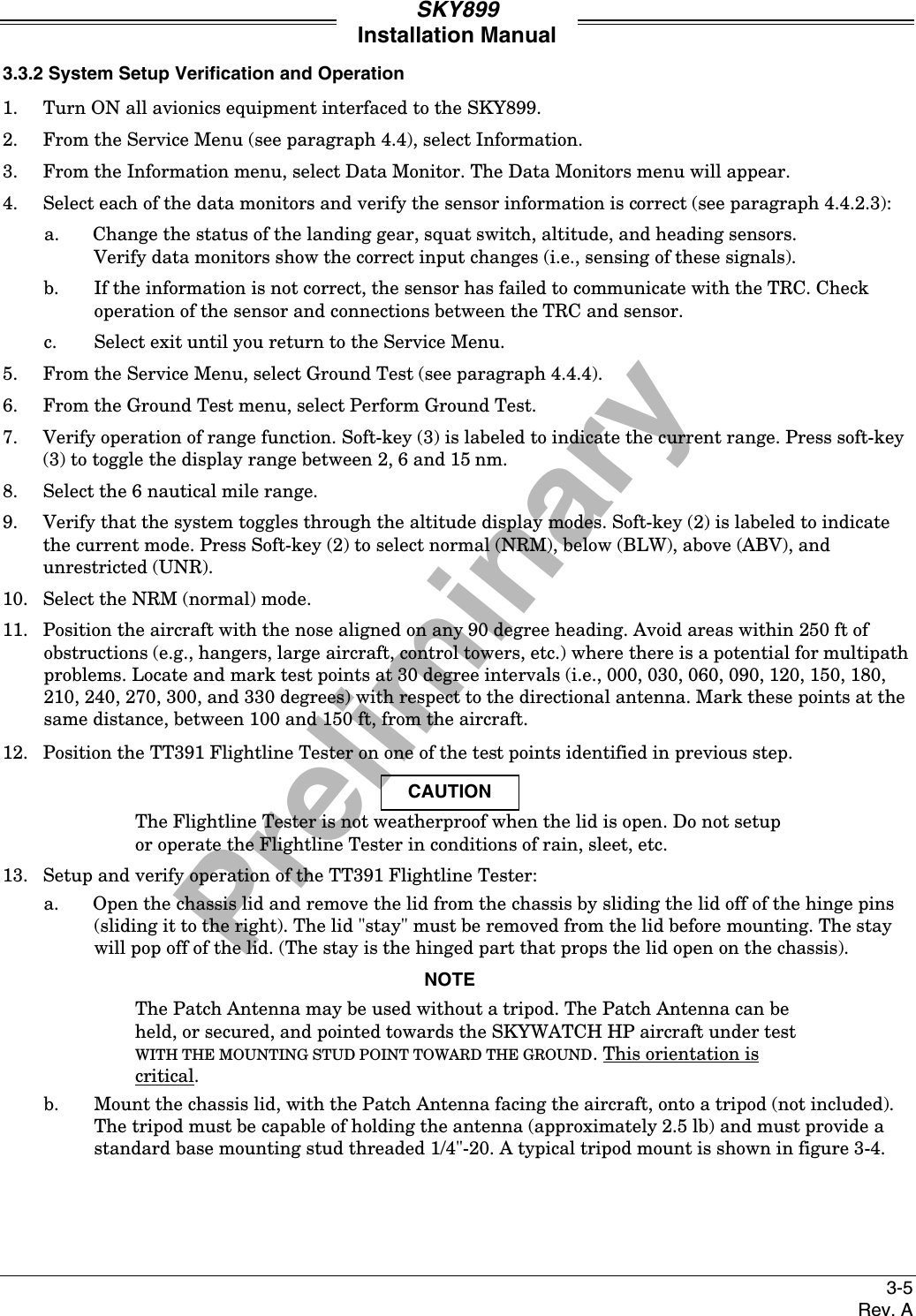
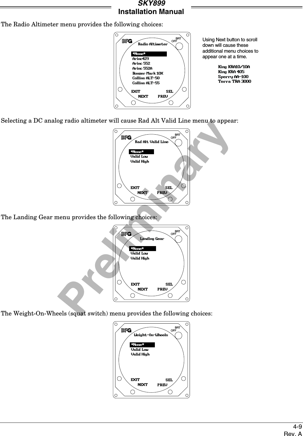
![PreliminarySKY899Installation Manual4-7Rev. A4.4.1.5 Avionics EquipmentAvionics equipment menu allows you to set the source equipment interfaced to SKY899 and sets discreteinputs. With all of the avionics turned on in the aircraft select Browse All Avionics from the avionicsequipment menu. This will sequentially step you through the setup of all avionics equipment interfaces.After completing Browse All Avionics selections, corrections can be made by selecting the individual itemsfrom the Equipment menu.The Avionics Equipment menu provides the following choices:BRTOFFEXITNEXTSELPREVEquipmentGPS Nav[Gama]Magnetic Heading[None]Barometric Altitude[None]Browse All AvionicsRadio Altitude[None]Landing Gear[None]Weight-On-Wheels[None]Audio Suppression[None]External Display[None]Using Next button to scrolldown will cause theseadditional menu choices toappear one at a time.If ARINC-429 equipment is selected in the avionics equipment menu, but was not configured in thecommunications port menu the following menu will appear:BRTOFFEXITNEXTSELPREVNo Chan AssignedCh.2: Multi 100 kHzCh.3: None 100 kHzCh.4: None 100 kHzCh.5: None 100 kHzCh.1: None 100 kHzChoose a channelThis Menu appears whenARINC 429 equipment hasbeen selected, but was notassigned to a channel viathe Communication Ports MenuThe Avionics Equipment sub-menus are as follows.The GPS Nav menu provides the following choices:BRTOFFEXITNEXTSELPREVGPS NavGAMAARINC 743A*None*](https://usermanual.wiki/L-3-Communications-Avionics-Systems/TRC899.Install-Manual/User-Guide-149253-Page-79.png)
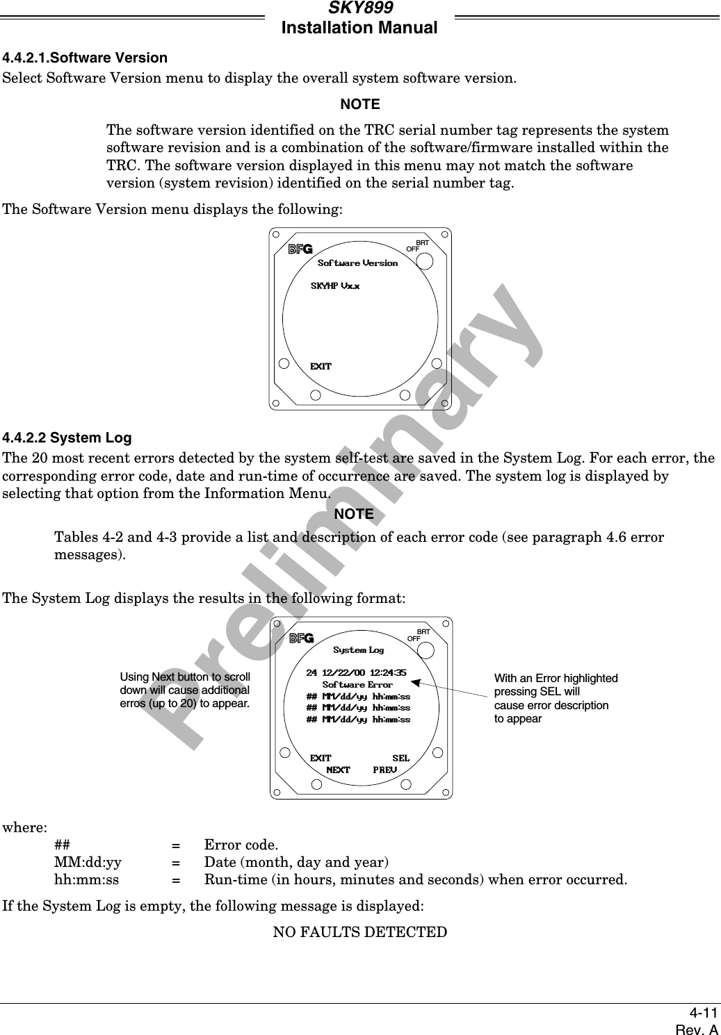
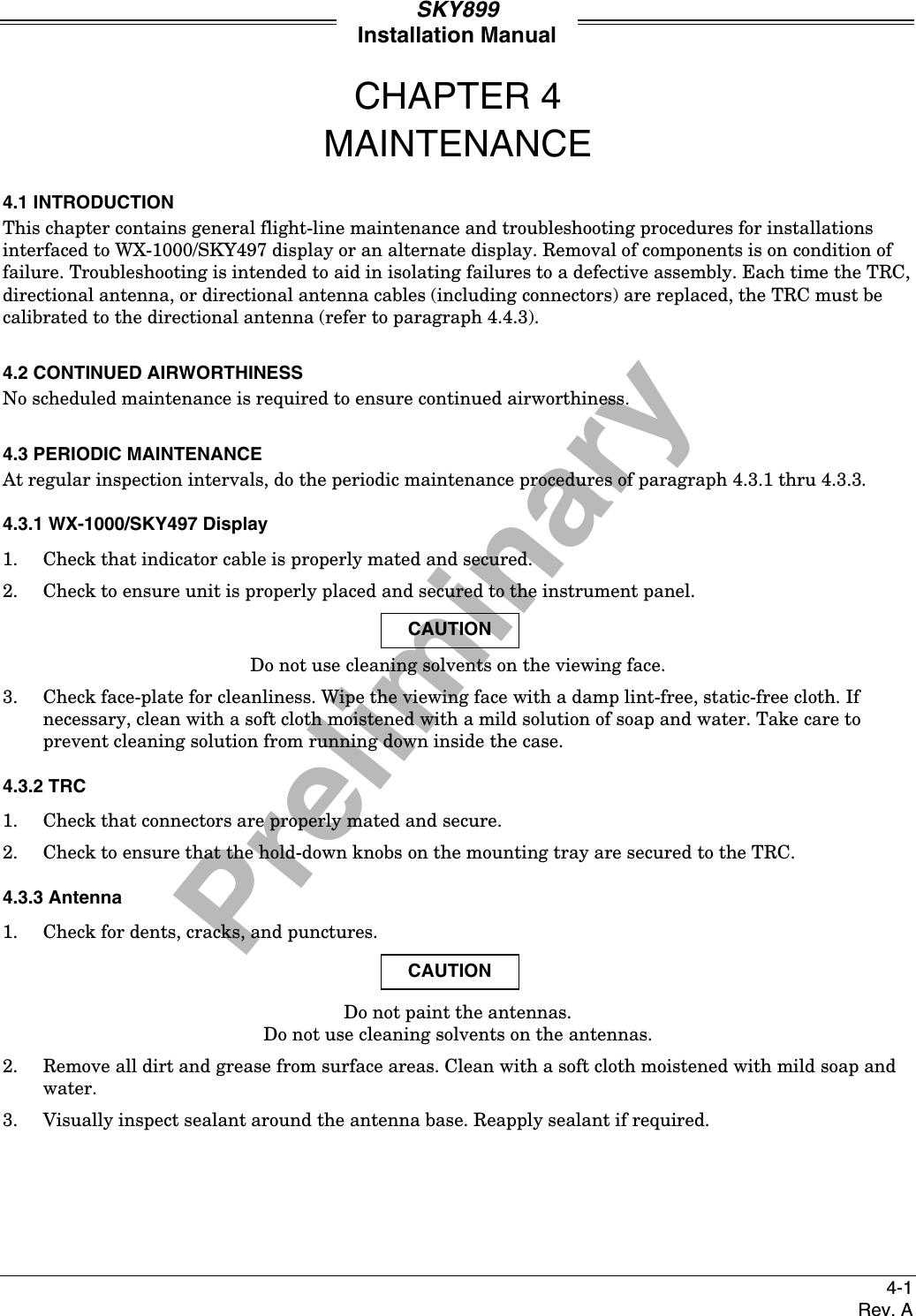
![PreliminarySKY899Installation Manual4-17Rev. ASERVICE MENUEXITNEXTSELPREVSetupInformationCalibrationGround TestConfig ManagementEXITNEXTSELPREVSetupAntenna SystemAudio LevelCommunication PortsAvionics EquipmentAircraft TypeEXITNEXTSELPREVAircraft TypeFixed WingRotor Craft*None*EXITNEXTSELPREVAntenna System*NY156 Directional*Bottom Antenna[None]Top AntennaEXITNEXTSELPREVArinc 429 ReceiversCh. 1: Multi 100 kHzCh. 2: None 100 kHzAutodetectEXITNEXTSELPREVEquipmentGPS Nav[Gama]Magnetic Heading[None]Barometric Altitude[None]Radio Altitude[None]Landing Gear[None]Weight-On-Wheels[None]Audio Suppression[None]External Display[None]Browse All AvionicsEXITNEXTSELPREVEquipment Type*ADC*AHRSRad AltNone*GPS*NEXTSELPREVSpeed100 kHz12.5 kHzEXITNEXTSELPREVArinc 429 Rx Ch 1Speed: 100 kHzType:EXITNEXTSELPREVTop AntennaNY164 DirectionalNY156 Directional*None*EXITNEXTSELPREVBottom AntennaNY164 DirectionalNY156 Directional*None*EXITNEXTSELPREVAudio Level[50%]VolumeUpDownTestAvionics Equipmentsubmenu on sheet 2 of 3Information Menu Sheet 3 of 3Calibration Menu Sheet 3 of 3Ground Test Menu Sheet 3 of 3Configuration ManagementMenu Sheet 3 of 3Ch. 3: None AutoCh. 4: None AutoCh. 5: None AutoADCGPSPlease wait... willbe displayed whileautodetect is beingperformedNEXTSELPREVSave or RevertChanges have been made!Revert to Old SettingsSave ChangesScreen appearswhen exiting Setupmenu and changeshave been madeFigure 4-3. Service Menu Tree (Sheet 1 of 3)](https://usermanual.wiki/L-3-Communications-Avionics-Systems/TRC899.Install-Manual/User-Guide-149253-Page-89.png)
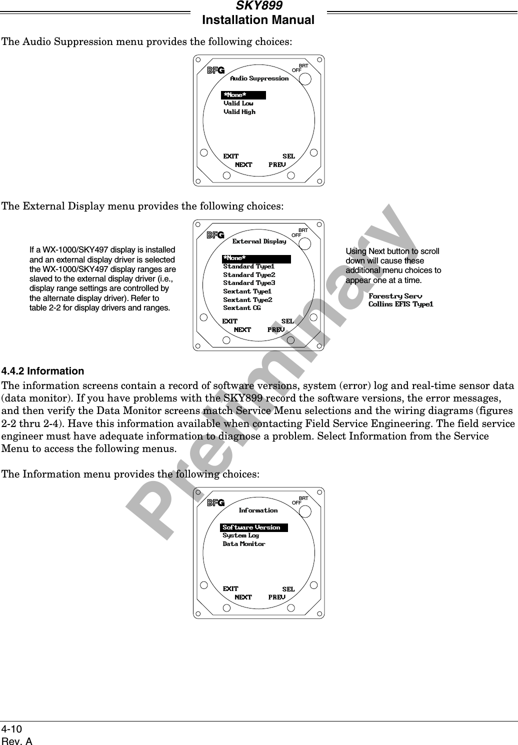
![PreliminarySKY899Installation Manual4-18Rev. AEXITNEXTSELPREVGPS NavGAMAARINC 743A*None*EXITNEXTSELPREVHeading Valid LineValid LowValid High*None*EXITNEXTSELPREVMagnetic HeadingSynchro CompassAHRS*None*EXITNEXTSELPREVEXITNEXTSELPREVRad Alt Valid LineValid LowValid High*None*EXITNEXTSELPREVLanding GearValid LowValid High*None*EXITNEXTSELPREVRadio AltimeterArinc429Arinc 552Arinc 552ABonzer Mark 10XCollins ALT-50Collins ALT-55King KRA10/10AKing KRA 405Sperry AA-100Terra TRA 3000*None*EXITNEXTSELPREVWeight-On-WheelsValid LowValid High*None*EXITNEXTSELPREVAudio SuppressionValid LowValid High*None*EXITNEXTSELPREVExternal DisplayStandard Type1Sextant Type2Sextant CGForestry ServCollins EFIS Type1*None*EXITNEXTSELPREVBarometric AltitudeADCEncoding Altimeter*None*EXITNEXTSELPREVADCARINC 429*None*Avionics Equipment Submenufrom Sheet 1 of 3EquipmentGPS Nav[Gama]Magnetic Heading[None]Barometric Altitude[None]Radio Altitude[None]Landing Gear[None]Weight-On-Wheels[None]Audio Suppression[None]External Display[None]Browse All AvionicsEXITNEXTSELPREVNo Chan AssignedCh.2: Multi 100 kHzCh.3: None 100 kHzCh.4: None 100 kHzCh.5: None 100 kHzCh.1: None 100 kHzChoose a channel Menu appears whenARINC 429 equipment hasbeen selected, but notassigned to a channel viathe Communication Ports MenuFigure 4-3. Service Menu Tree (Sheet 2 of 3)](https://usermanual.wiki/L-3-Communications-Avionics-Systems/TRC899.Install-Manual/User-Guide-149253-Page-90.png)
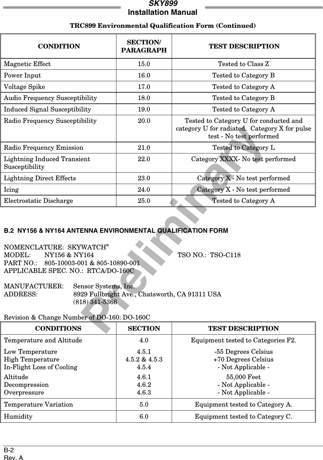
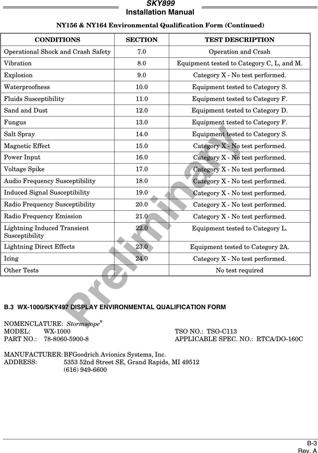
![PreliminarySKY899Installation ManualB-4Rev. ARevision & Change Number of DO-160: DO-160CCONDITION SECTION/PARAGRAPH TEST DESCRIPTIONTemperature and Altitude 4.0 Tested to Category F1-Operating Low Temperature 4.5.1 -20° CelsiusOperating High Temperature 4.5.3 +55° CelsiusShort-Time Operating High Temp. 4.5.2 +70° CelsiusLoss of Cooling 4.5.4 -Not Applicable-Ground Survival Low Temp. 4.5.1 -55° CelsiusGround Survival High Temp. 4.5.2 +85° CelsiusAltitude 4.6.1 55,000 Feet MSLTemperature Variation 5.0 Tested to Category CHumidity 6.0 Tested to Category AOperational Shock and Crash Safety 7.0Operational Shock 7.2 6 g's PeakCrash Safety 7.3 15 g's all axesVibration 8.0 Tested to Categories [NBM] InstrumentPanel Mount Without Vibration IsolatorsExplosion Proofness 9.0 Category X - No test requiredWaterproofness 10.0 Category X - No test requiredFluids Susceptibility 11.0 Category X - No test requiredSand and Dust 12.0 Category X - No test requiredFungus Resistance 13.0 Category X - No test requiredSalt Spray 14.0 Category X - No test requiredMagnetic Effect 15.0 Tested to Class ZPower Input 16.0 Category X - No test requiredVoltage Spike 17.0 Category X - No test requiredAudio Frequency Susceptibility 18.0 Category X - No test requiredInduced Signal Susceptibility 19.0 Tested to Category ZRadio Frequency Susceptibility 20.0 Tested to Category URadio Frequency Emission 21.0 Tested to Category ALightning Induced TransientSusceptibility22.0 Category X - No test requiredLightning Direct Effects 23.0 Category X - No test requiredIcing 24.0 Category X - No test requiredOther Tests X-Ray RadiationOther Tests U.V. RadiationOther Tests Thermal Shock](https://usermanual.wiki/L-3-Communications-Avionics-Systems/TRC899.Install-Manual/User-Guide-149253-Page-113.png)

![PreliminarySKY899Installation ManualE-2Rev. ACommands DescriptionsAttrib The attrib command allows you to view or change the attributes of a file.Attrib [filename]: Displays file and associated attributes. (If filename is leftblank all files with attributes will be displayed.)Attrib [[filename][+ or - [attrib]]]: Change attributes, + turns it on, - turns itoff.Attributes are:A - Archive attributeR - Read Only attributeS - System attributeH - Hidden attributeAttrib -?: Abbreviated help screen.Attrib --help: Help screen with descriptions.Attrib --about: About screen information.Baud The baud command allows you to change the communication baud ratebetween the system and the terminal device.Baud [rate]: Changes baud rate.Rates are: - <None> displays current baud rate.11520057600384001920096001200Baud -?: Abbreviated help screen.Baud --help: Help screen with descriptions.Baud --about: About screen information.Copy The copy command copies files on the compact flash, where filename1 is thesource file to be copied into filename2, the destination file.Copy [[filename1] [filename2]]: Makes duplicate copy of a file.Copy -?: Abbreviated help screen.Copy --help: Help screen with descriptions.Copy --about: About screen information.Del The del command allows you to delete a file (filename) located on thecompact flash.Del [filename]: Deletes file from compact flash.Del -?: Abbreviated help screen.Del --help: Help screen with descriptions.Del --about: About screen information.](https://usermanual.wiki/L-3-Communications-Avionics-Systems/TRC899.Install-Manual/User-Guide-149253-Page-125.png)
![PreliminarySKY899Installation ManualE-3Rev. ACommands DescriptionsDelay The delay command allows you to create a delay (pause) between commands.Can be useful when creating script files, it is intended for factory use only.Delay [milliseconds]: Delays specified amount of time [milliseconds] beforeexecuting the next command.Delay -?: Abbreviated help screen.Delay --help: Help screen with descriptions.Delay --about: About screen information.Dir The dir command will display all of the files located on the compact flash. Ifa compact flash is not present no information will appear.Dir: Lists all files located in a directory, if name is left blank itwill show all directories and files located on the compactflash.Dir -?: Abbreviated help screen.Dir --help: Help screen with descriptions.Dir --about: About screen information.DR The dr command allows flight data to be recorded to a compact flash and isintended for factory use only.DR [on/off]: Records flight data. DR on opens new file and startsrecording data. DR off stops recording data. If DR is on andDR on command is executed the old file is closed and a newfile is opened and starts recording data.Attrib -?: Abbreviated help screen.Attrib --help: Help screen with descriptions.Attrib --about: About screen information.Echo The echo command allows you verify communication between system andterminal device. Sent text will be displayed on the laptop if propercommunications has occurred.Echo [{text}]: Sends text through unit back to terminal device.Echo -?: Abbreviated help screen.Echo --help: Help screen with descriptions.Echo --about: About screen information.Edit The edit command allows you to edit a text file on the compact flash.Intended for factory use only.Edit [filename]: Opens file to be edited.Edit -?: Abbreviated help screen.Edit --help: Help screen with descriptions.Edit --about: About screen information.](https://usermanual.wiki/L-3-Communications-Avionics-Systems/TRC899.Install-Manual/User-Guide-149253-Page-126.png)
![PreliminarySKY899Installation ManualE-4Rev. ACommands DescriptionsHello The hello command allows you to see the start-up screen on the laptop (i.e.,company name, software version, etc.).Hello: Displays start up screen.Hello -?: Abbreviated help screen.Hello --help: Help screen with descriptions.Hello --about: About screen information.Help The help command displays a list of available commands.Help: Displays all available commands.Help [{cmdname}]: Help screen with descriptions for that command.Help [all]: Displays all available commands.Help -?: Abbreviated help screen.Help --help: Help screen with descriptions.Help --about: About screen information.Ident The ident command displays the vcs header information of all files. Intendedfor factory use only.Ident: Shows the vcs header information of all the files.Ident -?: Abbreviated help screen.Ident --help: Help screen with descriptions.Ident --about: About screen information.Menu The menu command allows the system to enter the service menu. There areno help screens are available, type the prefix character (1, 2, x, etc.) toperform that operation.Example:Service Menu1 Setup2 Information3 Calibration4 Ground Testx ExitRen The ren command allows you to rename a file located on the compact flash.Ren [{oldfilename} {newfilename}]: Changes file name.Ren -?: Abbreviated help screen.Ren --help: Help screen with descriptions.Ren --about: About screen information.](https://usermanual.wiki/L-3-Communications-Avionics-Systems/TRC899.Install-Manual/User-Guide-149253-Page-127.png)
![PreliminarySKY899Installation ManualE-5Rev. ACommands DescriptionsRepeat The repeat command allows you to repeat a command a specific number oftimes with a specified amount of time delay between the commandsexecution.Repeat [{number} {delay} {command}]: Repeats command.{number} - number of times to be repeated, zero will cause command torepeat until a key is pressed.{delay} - number of milliseconds delay between commands.{command}- command to be repeated.Repeat -?: Abbreviated help screen.Repeat --help: Help screen with descriptions.Repeat --about: About screen information.Time The SKY899 does not have a real-time clock. The time command allows youto see the time received via the GPS nav information, if available. If notavailable, the time displayed will be the software creation date.Time: The year is :2000The month is :8The hour is :13The minute is :51The second is :38The millisecond is :3Time -?: Abbreviated help screen.Time --help: Help screen with descriptions.Time --about: About screen information.Type The type command allows you to see the contents of a file.Type [{filename}]: Displays the contents of a file.Type -?: Abbreviated help screen.Type --help: Help screen with descriptions.Type --about: About screen information.Ver The ver command allows you to see the system software version. It includesthe following information: MQX Copyright, MQX Library Creation Date,MQX Version, Build Copyright, Build Version, Build MakeDate, BuildMakeTime, CPU Type, and CPU Number.Ver: Displays system software version.Ver -?: Abbreviated help screen.Ver --help: Help screen with descriptions.Ver --about: About screen information.](https://usermanual.wiki/L-3-Communications-Avionics-Systems/TRC899.Install-Manual/User-Guide-149253-Page-128.png)