L3 Fuzing and Ordnance Systems 25STW4100-029 2.4GHz Wifi Module User Manual 72126853 Manual Coverx
L-3 Communications CyTerra Corporation 2.4GHz Wifi Module 72126853 Manual Coverx
Manual

3998 FAU Blvd., Suite 310, Boca Raton, FL 33431 Phone: (561) 961-5585
Certification Exhibit
FCC ID: YKD-25STW4100-029
FCC Rule Part: 15.247
TÜV SÜD Project Number: 72126853
Manufacturer: L3 Communications, CyTerra Division
Model: HF-A11-SMT-0
Manual
Approved for Public Release 20 October
2015 by U.S. Army Project Manager I2WD
10/9/2017 Approved for Public Release 20 October
2015 by U.S. Army Project Manager I2WD 1
CyTerra
RANGE-R2D
OPERATION &TRAINING MANUAL

Approved for Public Release 20 October
2015 by U.S. Army Project Manager I2WD
10/9/2017 Approved for Public Release 20 October
2015 by U.S. Army Project Manager I2WD 2
CyTerra
FCC Required Information
•Warning: Changes or modifications to this device not expressly approved by L-3 CyTerra could void the
user’s authority to operate the equipment
•NOTE: This equipment has been tested and found to comply with the limits for a Class B digital device,
pursuant to Part 15 of the FCC Rules. These limits are designed to provide reasonable protection against
harmful interference in a residential installation. This equipment generates, uses, and can radiate radio
frequency energy and, if not installed and used in accordance with the instructions, may cause harmful
interference to radio communications. However, there is no guarantee that interference will not occur in a
particular installation. If this equipment does cause harmful interference to radio or television reception,
which can be determined by turning the equipment off and on, the user is encouraged to try to correct the
interference by one or more of the following measures:
–Reorient or relocate the receiving antenna.
–Increase the separation between the equipment and receiver.
–Connect the equipment into an outlet on a circuit different from that to which the receiver is connected.
–Consult the dealer or an experienced radio/TV technician for help.
•This equipment complies with radiation exposure limits set forth for an uncontrolled environment. This
equipment is in direct contact with the body of the user under normal operating conditions. This
transmitter must not be co-located or operating in conjunction with any other antenna or transmitter.

Approved for Public Release 20 October
2015 by U.S. Army Project Manager I2WD
10/9/2017 Approved for Public Release 20 October
2015 by U.S. Army Project Manager I2WD 3
CyTerra
LESSON 1
Description and Capabilities

Approved for Public Release 20 October
2015 by U.S. Army Project Manager I2WD
10/9/2017 Approved for Public Release 20 October
2015 by U.S. Army Project Manager I2WD 4
CyTerra
INSTRUCTION POINTS
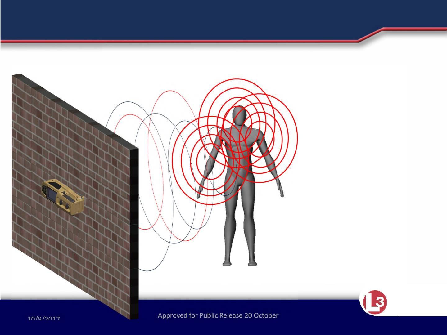
•The RANGE-R2D system is a portable, handheld, battery-operated system
designed to detect moving and near-stationary targets through walls
constructed of common building materials.
•The system is comprised of a stepped-frequency,continuous-wave radar
transceiver, digital signal processor, display and power supply electronics
enclosed in a rugged, water-resistant, lightweight plastic housing.
•The operator controls consist solely of the two momentary push-button
switches located on the sides of the system.
•The graphics display on the front of the system presents target detection
information and system status.
•The display is easy to use, alerts are simple to interpret, and detection is
nearly immediate.
Approved for Public Release 20 October
2015 by U.S. Army Project Manager I2WD
10/9/2017 Approved for Public Release 20 October
2015 by U.S. Army Project Manager I2WD 5
CyTerra
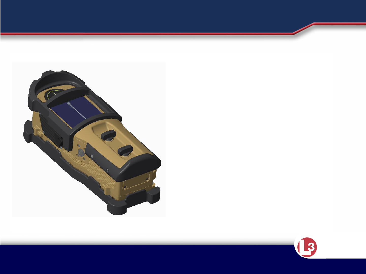
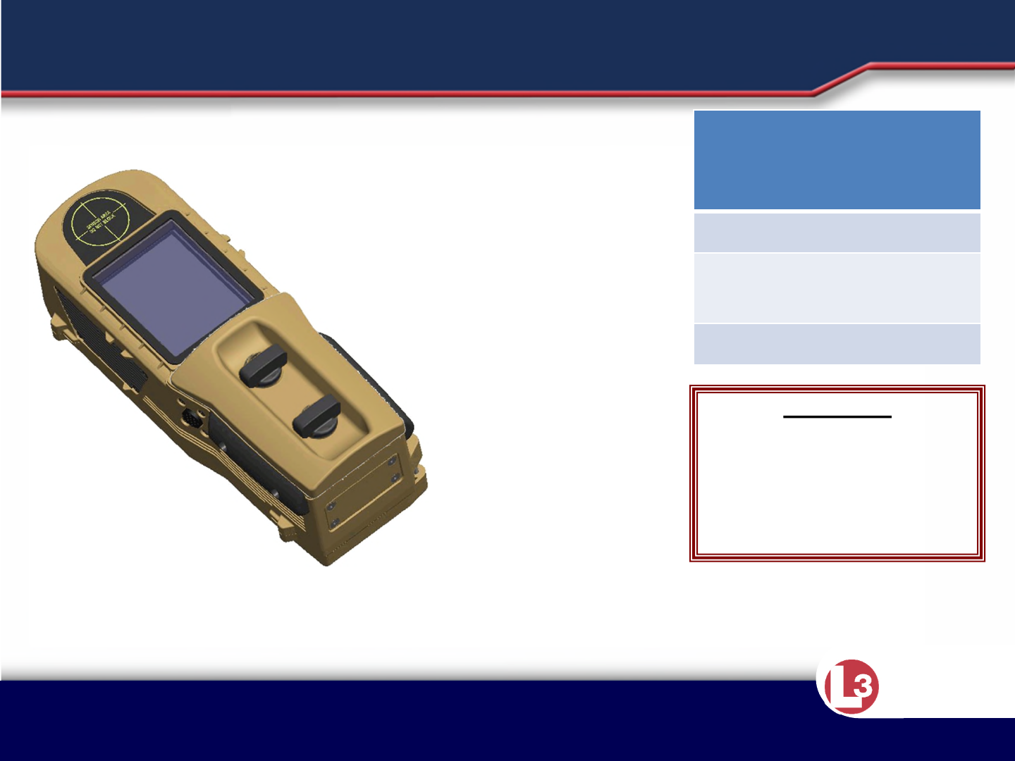
The RANGE-R2D is lightweight and
compact. It is designed to detect
moving and near stationary objects
through walls constructed of common
building materials.
GENERAL
Approved for Public Release 20 October
2015 by U.S. Army Project Manager I2WD
10/9/2017 Approved for Public Release 20 October
2015 by U.S. Army Project Manager I2WD 6
CyTerra
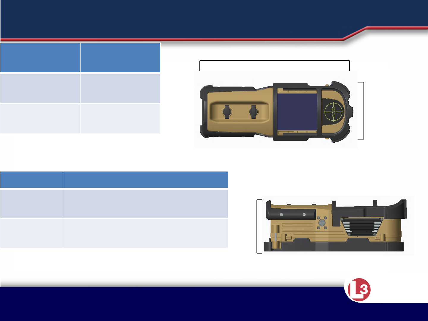
Item Dimensions
RANGE-
R2D Unit 10”x3.6”x3.9”
(25.4cm x 9.14cm x 9.91cm)
Storage
Container 16.3”x12.8”x6.8”
(41.4cm x 32.51cm x 17.27cm)
11”
4”
4”
MECHANICAL DATA
Item Weight
RANGE-R2D
Unit 3 lbs
(1.36 kg)
Storage
Container 6.1 lbs
(2.77 kg)

Approved for Public Release 20 October
2015 by U.S. Army Project Manager I2WD
10/9/2017 Approved for Public Release 20 October
2015 by U.S. Army Project Manager I2WD 7
CyTerra
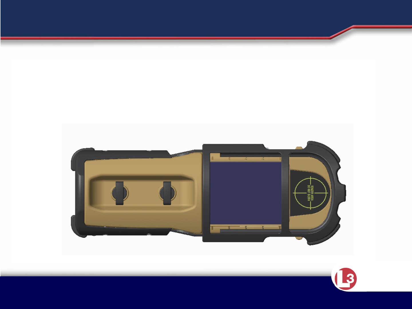
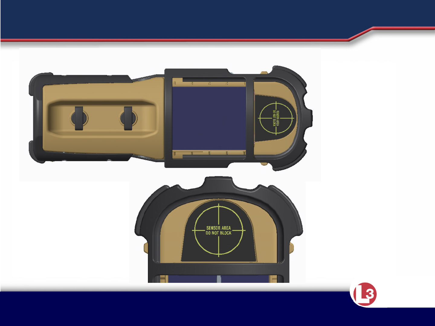
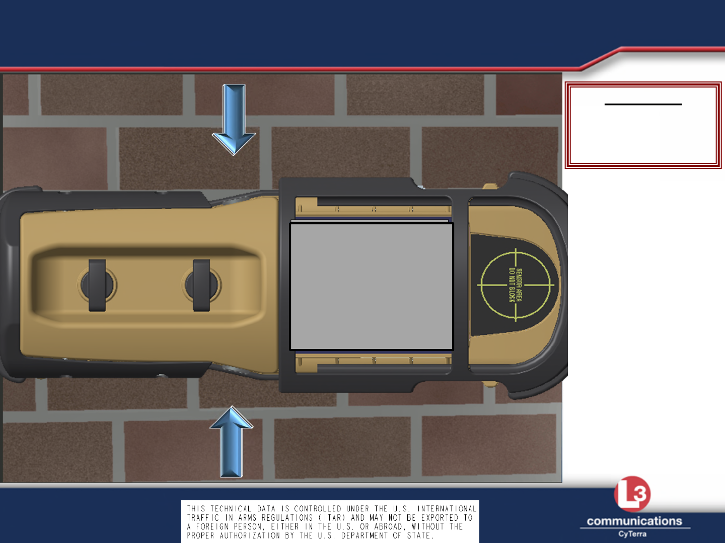
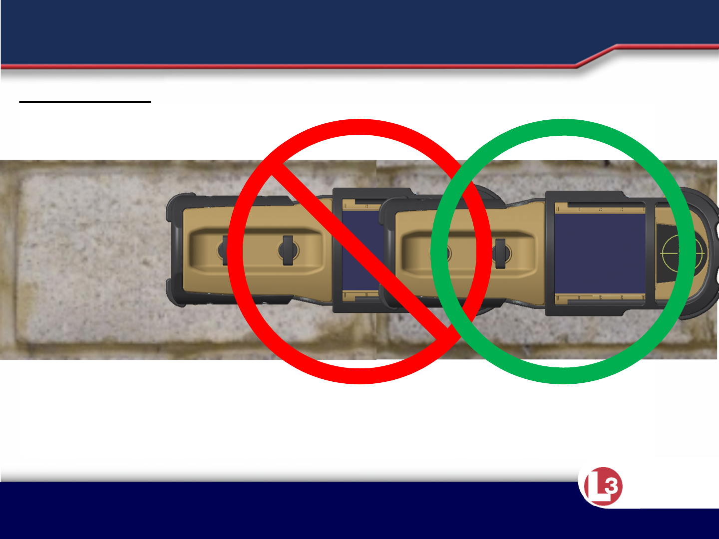
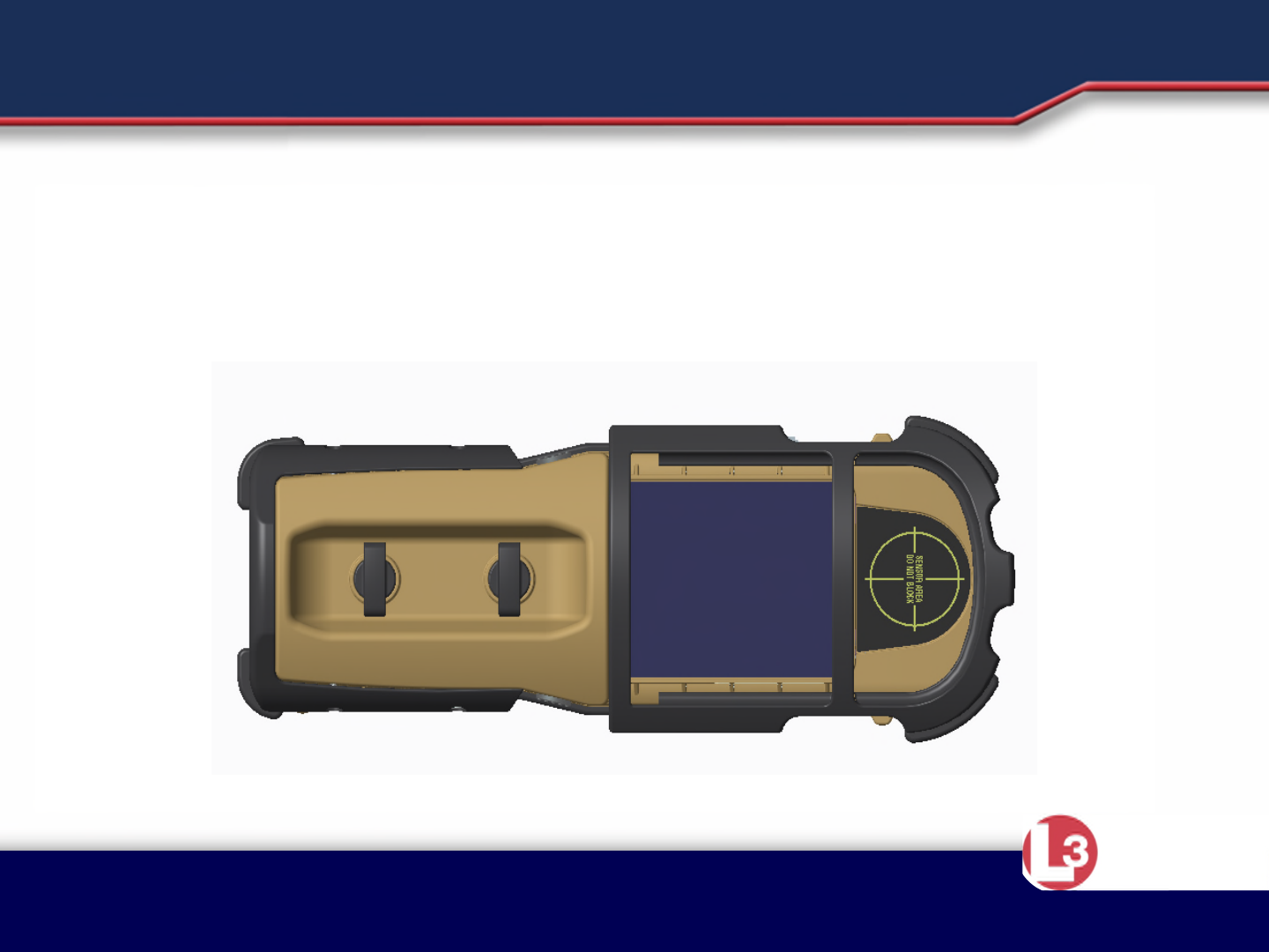
•The major components are as follows:
•Rotational View LCD– displays target information. The display will rotate
to match the long axis of system orientation. THIS WILL NOT WORK WITH
THE SYSTEM WITH THE LONG AXIS ORIENTED VERTICALLY.
•Scan Buttons (X2) – to perform all system operations. Scan Buttons will
also rotate to match the LCD screen.
•Battery Lid – secures the battery compartment, keeps moisture away from
the batteries.
•Rearward Antenna – helps reduce false alarm rate, The Operator should
NEVER cover this antenna.
•Receive Antenna – receives radar waves sent from the transmit antenna
•Transmit Antenna – transmits radar waves to locate targets.
INSTRUCTION POINTS
Approved for Public Release 20 October
2015 by U.S. Army Project Manager I2WD
10/9/2017 Approved for Public Release 20 October
2015 by U.S. Army Project Manager I2WD 8
CyTerra
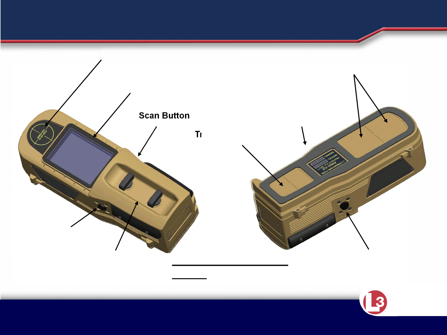
Top Left View Bottom Right View
Scan Button
Receive Antenna
Transmit Antenna
MAJOR COMPONENTS
Scan Button Scan Button
Scan Button
Battery
Lid
Rotational View LCD
Rearward Looking Receive Antenna
Bumpers removed for
Clarity

Approved for Public Release 20 October
2015 by U.S. Army Project Manager I2WD
10/9/2017 Approved for Public Release 20 October
2015 by U.S. Army Project Manager I2WD 9
CyTerra
INSTRUCTION POINTS
•The rearward looking antenna faces the operator and helps reduce the
influence of the operator and other “friendly” movers that could
otherwise appear as targets on the readout display.
•The rearward antenna should never be blocked during operation.
•Avoid blocking the rearward antenna when stabilizing the system.
•For both left- and right-handed use, the operator’s hand will cover the
battery compartment.
•If possible the operator should hold the sensor in the prone position
without blocking the line of site for the rear antenna. Stabilize the sensor
at eye level for best results.
•Keep operator movement to a minimum.
Approved for Public Release 20 October
2015 by U.S. Army Project Manager I2WD
10/9/2017 Approved for Public Release 20 October
2015 by U.S. Army Project Manager I2WD 10
CyTerra
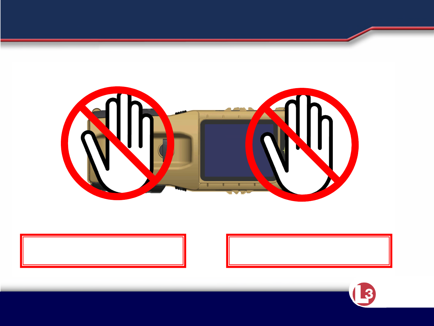
REARWARD LOOKING ANTENNA
Used to help reduce
false alarms caused
by the operator and
or people around
the operator.
DO NOT BLOCK
the rearward looking
antenna with your
non-operating hand
when trying to
stabilize the system.
Hold the system at
eye level when
operating.
Operating hand
will cover the
battery
compartment.

Approved for Public Release 20 October
2015 by U.S. Army Project Manager I2WD
10/9/2017 Approved for Public Release 20 October
2015 by U.S. Army Project Manager I2WD 11
CyTerra
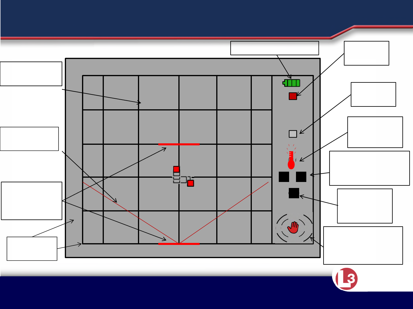
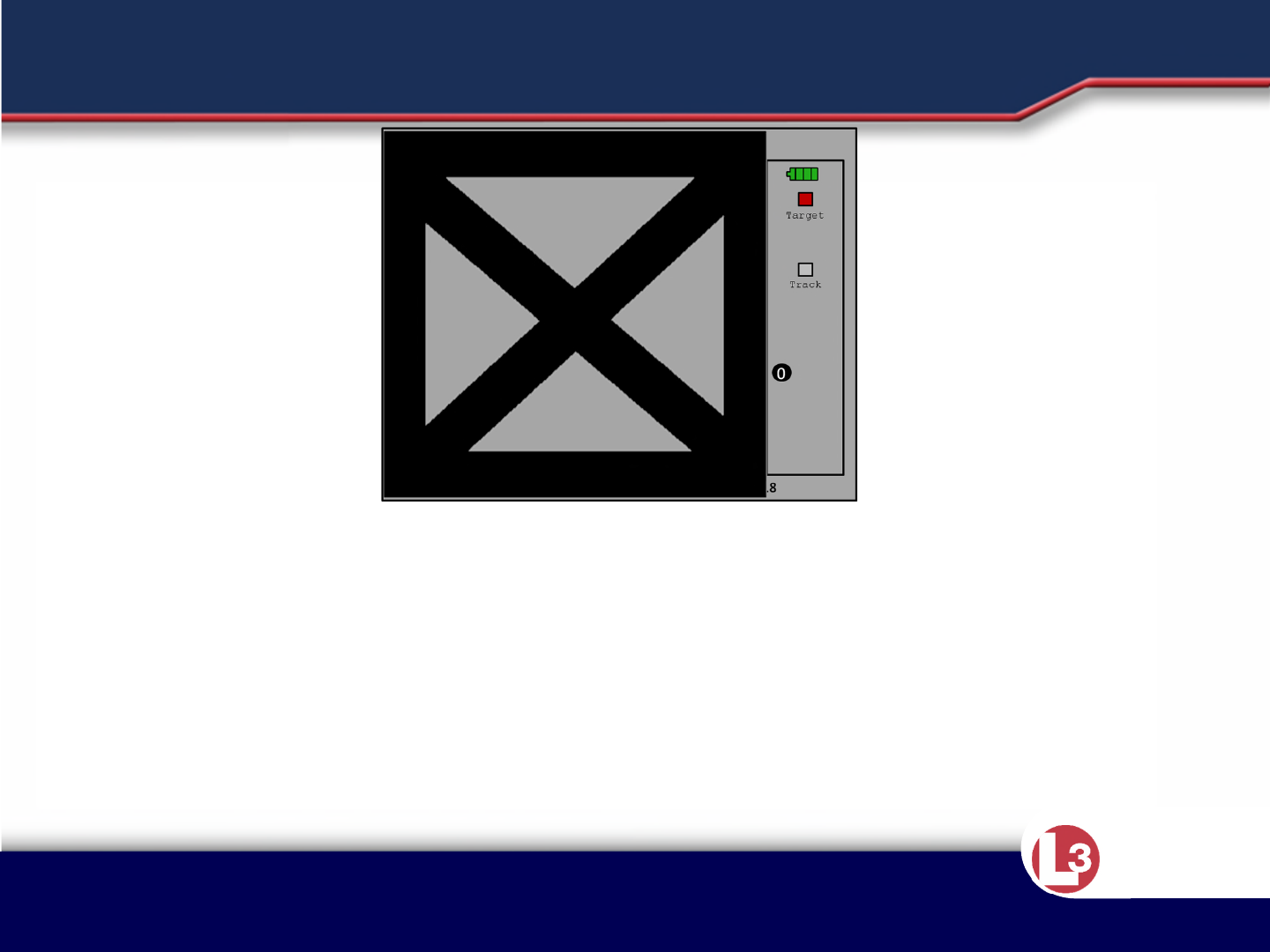
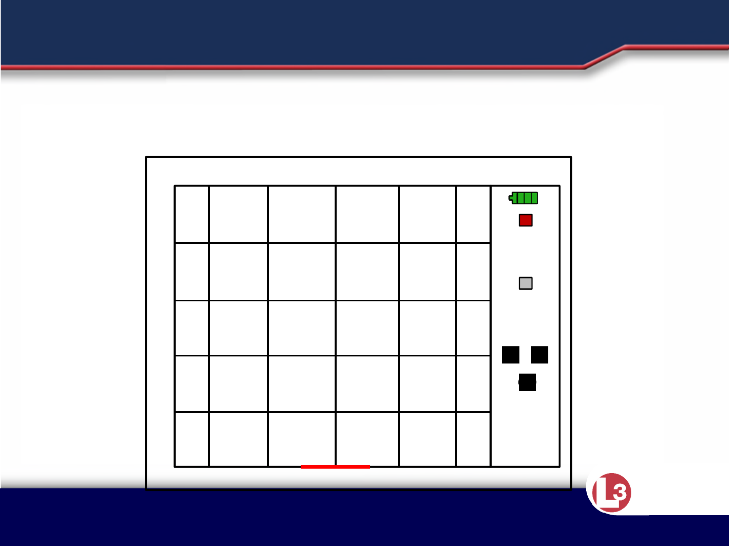
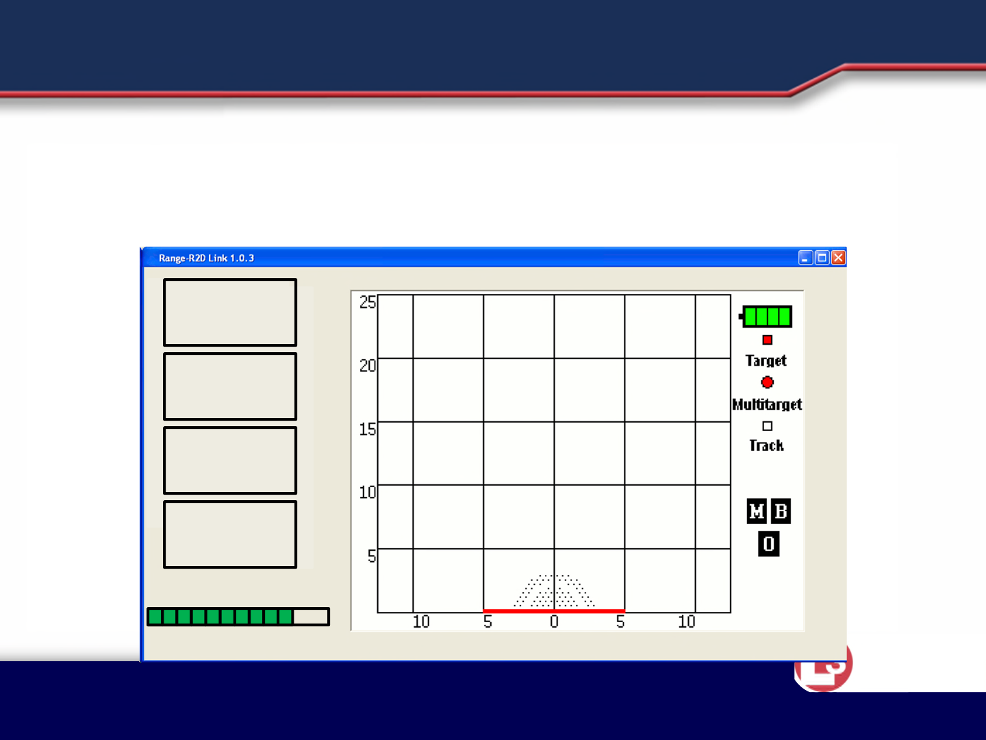
•Battery Indicator: Represents battery life of the system
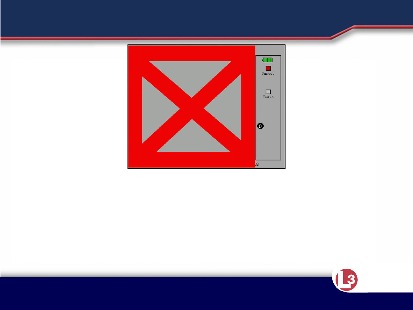
•Target Indicator: The red square indicates one target. The red square will also indicate more than
one target in an area if they are close to each other.
•Track Indicator: Represents a detected target’s last position
•Over-temp Indicator: System has reached an internal temperature of 80 degrees Celsius and will
shut off at 85 degrees Celsius.
•Operator Movement Indicator: Informs the operator that excessive movement of the system could
be affecting the systems performance.
•Excessive Backside Movement Indicator: Lets the operator know there is too much movement
behind the system for it to work properly.
•Target Display Grid: Displays all target information (in meters)
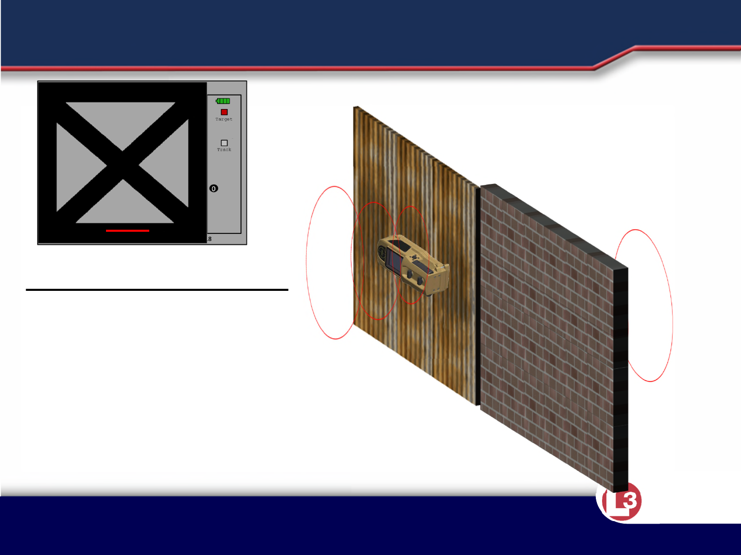
•Horizontal Red Lines on the Display: The first two walls detected by the system. Only 2 can be
shown at a time.
•Number of Targets Indicator: Displays the total number of targets detected as a numeric value.
•Field of view lines: Displays the area of detection the system is currently scanning in. NOTE: FOV off
if wall coupled, FOV on if standoff.
INSTRUCTION POINTS
Approved for Public Release 20 October
2015 by U.S. Army Project Manager I2WD
10/9/2017 Approved for Public Release 20 October
2015 by U.S. Army Project Manager I2WD 12
CyTerra
0
5
10 5 5 10
10
15
20
25
Target
Track
###
Operator
movement
indicator/ Excessive
backside motion
Target display
grid
Brightness
level/
Over-temp
Wall as seen by
the
system
Multitarget
Target
indicators
Battery indicator
Number of
detected
targets
Field of view
indicators
LCD SCREEN LAYOUT – Indoor/Against Wall Use
Display
Is in Meters
M B
01
Mover &
Breather Processing
Status
BACK
MOTION
Track
indicator

Approved for Public Release 20 October
2015 by U.S. Army Project Manager I2WD
10/9/2017 Approved for Public Release 20 October
2015 by U.S. Army Project Manager I2WD 13
CyTerra
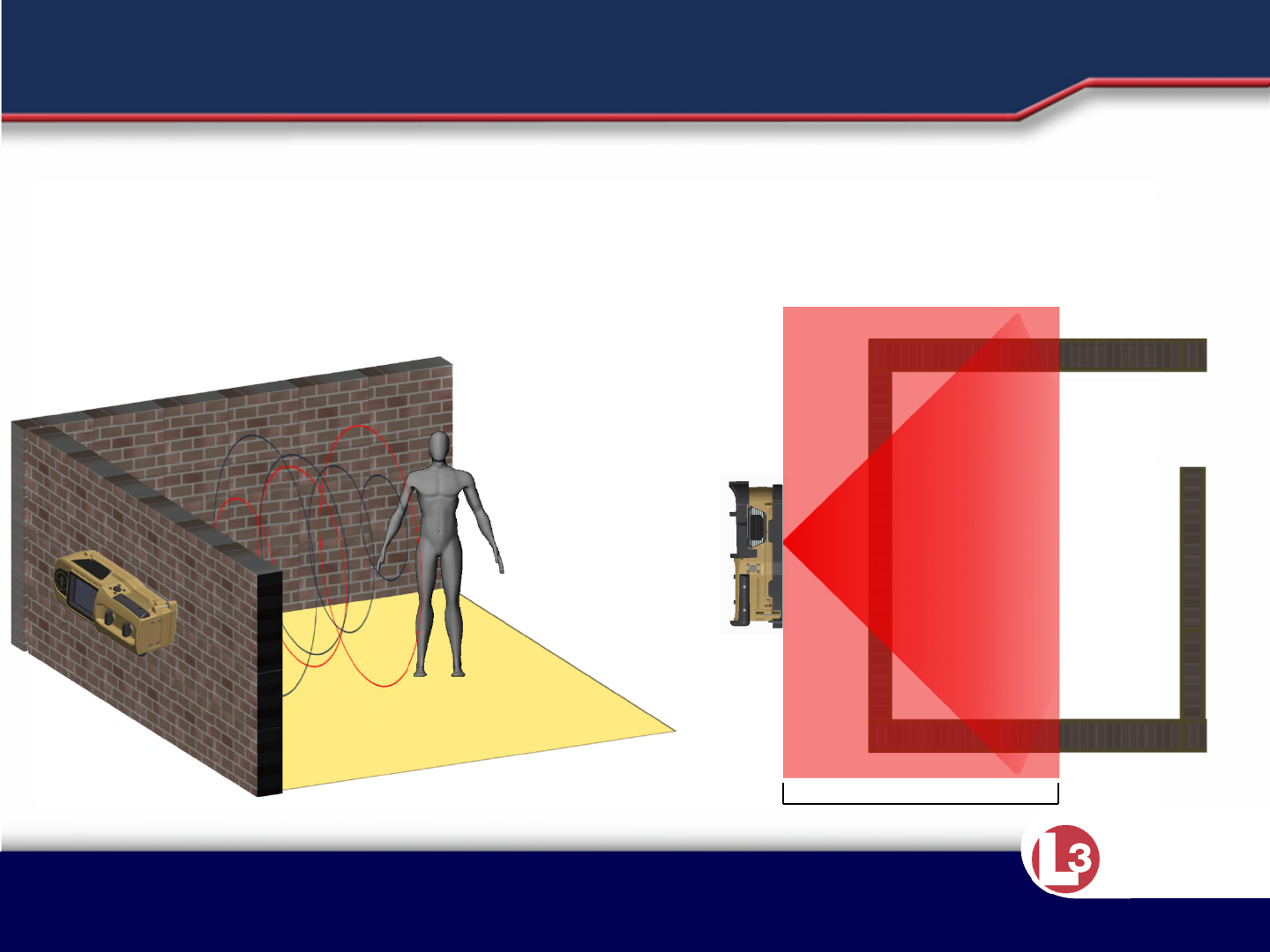
•The system transmits radar waves into the target area.
•All solid objects in that area reflect the waves.
•The system receives these reflected waves, processes the return, and
analyzes the data using principles of Doppler radar to detect moving
objects and identify possible targets.
INSTRUCTION POINTS
Approved for Public Release 20 October
2015 by U.S. Army Project Manager I2WD
10/9/2017 Approved for Public Release 20 October
2015 by U.S. Army Project Manager I2WD 14
CyTerra
Radar waves are transmitted into the target area. The radar waves are
then reflected by solid objects. The system detects these reflected
waves, analyzes them, and interprets them on the LCD. The sensor can
be placed against the wall or from standoff.
THEORY OF OPERATION
25 meters

Approved for Public Release 20 October
2015 by U.S. Army Project Manager I2WD
10/9/2017 Approved for Public Release 20 October
2015 by U.S. Army Project Manager I2WD 15
CyTerra
•Relative motion is the changing distance between two objects. In other
words, it is the relative speed between these objects.
•A radar signal reflected off a stationary object (no relative motion) would
return at the same frequency as it was transmitted.
•When the target is approaching or moving towards the transmitter, the
radar signal reflected off the object will be compressed and the returned
frequency will be higher than the frequency that was transmitted.
•Conversely, a radar signal reflected off an object moving away from the
transmitter/receiver will be stretched.
•The reflected (returned) signal will be of a lower frequency than the
transmitted signal.
INSTRUCTION POINTS
Approved for Public Release 20 October
2015 by U.S. Army Project Manager I2WD
10/9/2017 Approved for Public Release 20 October
2015 by U.S. Army Project Manager I2WD 16
CyTerra
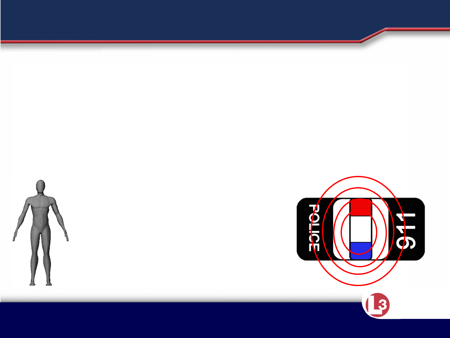
DOPPLER EFFECT
Radar waves reflected from a stationary target will remain constant. Radar waves
reflected from a moving object will be compressed if the object is approaching or
stretched if the object is receding.
Approved for Public Release 20 October
2015 by U.S. Army Project Manager I2WD
10/9/2017 Approved for Public Release 20 October
2015 by U.S. Army Project Manager I2WD 17
CyTerra
DOPPLER EFFECT
Each movement from the
target will have an effect
on the Doppler. These
movements will be
detected by the system
and displayed on the LCD.
•Breathing
•Limb Movement
• Unintentional Micro-
Movements

Approved for Public Release 20 October
2015 by U.S. Army Project Manager I2WD
10/9/2017 Approved for Public Release 20 October
2015 by U.S. Army Project Manager I2WD 18
CyTerra
•The RANGE-R2D detects targets up to a range of 25 m from the sensor.
•The RANGE-R2D senses motion through non-metallic walls and barriers of
different materials such as drywall, adobe, cinderblock, and rebar
reinforced concrete. It has been tested through walls up to 12” thick, but
may not be limited to this material depth dependent upon composition
and density.
•The system is water resistant up to 4 feet for 30 minutes. The system
would have to be held underwater to stay submerged, otherwise it would
float.
INSTRUCTION POINTS

Approved for Public Release 20 October
2015 by U.S. Army Project Manager I2WD
10/9/2017 Approved for Public Release 20 October
2015 by U.S. Army Project Manager I2WD 19
CyTerra
CAPABILITIES
Function Performance
Max effective range 25 meters (from sensor)
Minimum mobile target
acquisition time
5 seconds
Minimum stationary target*
acquisition time
30 seconds
Accuracy 2 meters in range or cross
range
Field of View +/-80° from center (open air)
Water resistant 4 feet for 30 minutes
* A target that exhibits activity but does not
change position

Approved for Public Release 20 October
2015 by U.S. Army Project Manager I2WD
10/9/2017 Approved for Public Release 20 October
2015 by U.S. Army Project Manager I2WD 20
CyTerra
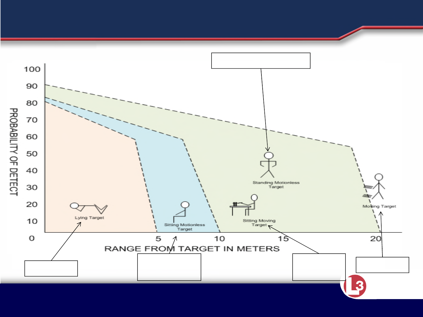
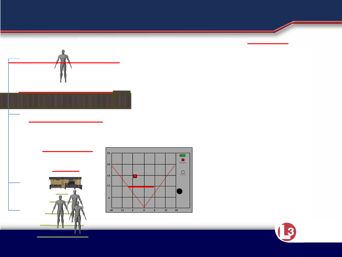
CAPABILITIES
Detect Time ≈
30 Sec Detect Time ≈ 15 Sec
Detect
Time ≈
30 Sec
Detect Time ≈
5 Sec
Prone Seated
(min move)
Standing (min move)
Seated
(moving) Moving

Approved for Public Release 20 October
2015 by U.S. Army Project Manager I2WD
10/9/2017 Approved for Public Release 20 October
2015 by U.S. Army Project Manager I2WD 21
CyTerra
LESSON 2
Operation

Approved for Public Release 20 October
2015 by U.S. Army Project Manager I2WD
10/9/2017 Approved for Public Release 20 October
2015 by U.S. Army Project Manager I2WD 22
CyTerra
•Prior to operation, batteries need to be installed into the RANGE-R2D
system.
•The RANGE-R2D is designed to operate on eight standard “AA” sized 1.5v
lithium batteries.
•Alkaline AA, and 1.5v Nickel Metal Hydride AA batteries can be used in the
system, but will not give you maximum performance from the system.
•Failure to install the batteries properly will cause the system to
malfunction.
•To install the batteries, remove the battery door by unscrewing the
thumbscrew located at the top of the unit. Insert all batteries as the
diagram inside the case states.
•Replace the battery cover and secure it by hand tightening the
thumbscrews.
•Do not mix the types of batteries that are in the system at one time.
INSTRUCTION POINTS
Approved for Public Release 20 October
2015 by U.S. Army Project Manager I2WD
10/9/2017 Approved for Public Release 20 October
2015 by U.S. Army Project Manager I2WD 23
CyTerra
BATTERY INSTALLATION
WARNING
Installing the batteries
incorrectly will cause the
system to malfunction.
DO NOT MIX BATTERY
TYPES!!
Functional Batteries
(in order of
performance)
1.5v Lithium (L-91)
1.5v Nickel Metal
Hydride
Alkaline
Note: Bumpers removed for clarity

Approved for Public Release 20 October
2015 by U.S. Army Project Manager I2WD
10/9/2017 Approved for Public Release 20 October
2015 by U.S. Army Project Manager I2WD 24
CyTerra
Battery Type
(“AA” Size x
8)
Operational
Condition
(On/Off Cycle)
Battery Life vs. Temp
-20°C
(-4°F) 25°C
(77°F) 50°C
(122°F)
Lithium 30 sec/3 min 9.1 hrs 11.7 hrs 12.75 hrs
NiMH 30 sec/3 min 6.5 hrs 6.6 hrs 8.3 hrs
Alkaline 30 sec/3 min 0.25 hrs 3.1 hrs 5.8 hrs
Lithium 1 min/6 min 9 hrs 11.6 hrs 13 hrs
NiMH 1 min/6 min 8.25 hrs 8.5 hrs 8.75 hrs
Alkaline 1 min/6 min 0.33 hrs 2.8 hrs 5.5 hrs
Lithium Continuous 1.2 hrs 1.5 hrs 1.4 hrs
NiMH Continuous 0.9 hrs 1.25 hrs 1.25 hrs
Alkaline Continuous 1 min 24 min 37 min
BATTERY COMPATIBILTY/PERFORMANCE

Approved for Public Release 20 October
2015 by U.S. Army Project Manager I2WD
10/9/2017 Approved for Public Release 20 October
2015 by U.S. Army Project Manager I2WD 25
CyTerra
•Operator controls consist solely of the two momentary push button
switches referred to as scan buttons located on the sides of the system.
•These two buttons perform the several functions: they power on the
system, power off the system, adjust the brightness, and navigate the user
interface.
•The sensor contains an inertial measurement unit that automatically
detects the orientation of the sensor for single button specific functions.
INSTRUCTION POINTS

Approved for Public Release 20 October
2015 by U.S. Army Project Manager I2WD
10/9/2017 Approved for Public Release 20 October
2015 by U.S. Army Project Manager I2WD 26
CyTerra
Function Sequence
Power-On Press and release both Scan Buttons. Sensor will
boot to Menu Mode.
Power-Off Press and hold both Scan Buttons for 3 seconds.
Brightness Control In the Main Menu select brightness and press either
up or down to brighten or dim the display.
Zoom Selection In Scan Mode, press the bottom Scan button to
zoom in.
Main Menu Press and release both Scan Buttons while in Scan
Mode.
Cycle Menu Options Press the bottom Scan Button while in Menu Mode.
Select Menu Option Press the top Scan Button while the selection is
highlighted.
Scan Mode Press and release both Scan Buttons from any other
mode or menu.
CONTROL SEQUENCE

Approved for Public Release 20 October
2015 by U.S. Army Project Manager I2WD
10/9/2017 Approved for Public Release 20 October
2015 by U.S. Army Project Manager I2WD 27
CyTerra
•With batteries installed, aim the system in the desired direction (either
against a wall or in stand off) and press and release the two scan buttons.
•Tracking of moving targets will start in a minimum of three seconds.
INSTRUCTION POINTS

Approved for Public Release 20 October
2015 by U.S. Army Project Manager I2WD
10/9/2017 Approved for Public Release 20 October
2015 by U.S. Army Project Manager I2WD 28
CyTerra
HOLDING THE SYSTEM
Wall Coupled Use:
• Select Wall Mode
• Thumb and index finger operating
scan buttons
• Palm covering battery compartment
• Hold at eye level
•DO NOT COVER OR BLOCK
REARWARD LOOKING ANTENNA!
•DO NOT COVER OR BLOCK
FORWARD LOOKING ANTENNAS!
Stand Off Use:
•Mount sensor on tripod or monopod
•Select Standoff Mode
•DO NOT COVER OR BLOCK
REARWARD LOOKING ANTENNA!
•DO NOT COVER OR BLOCK
FORWARD LOOKING ANTENNAS!
SYSTEM INITIALIZATION
WARNING
Do not block
rearward antenna
while scanning.
Once the system
is in the desired
position (flush to
the wall or aimed
at the target
structure),
depress and
release the Scan
Buttons
Note: Bumpers
removed for
clarity
Approved for Public Release 20 October
2015 by U.S. Army Project Manager I2WD
10/9/2017 Approved for Public Release 20 October
2015 by U.S. Army Project Manager I2WD 30
CyTerra
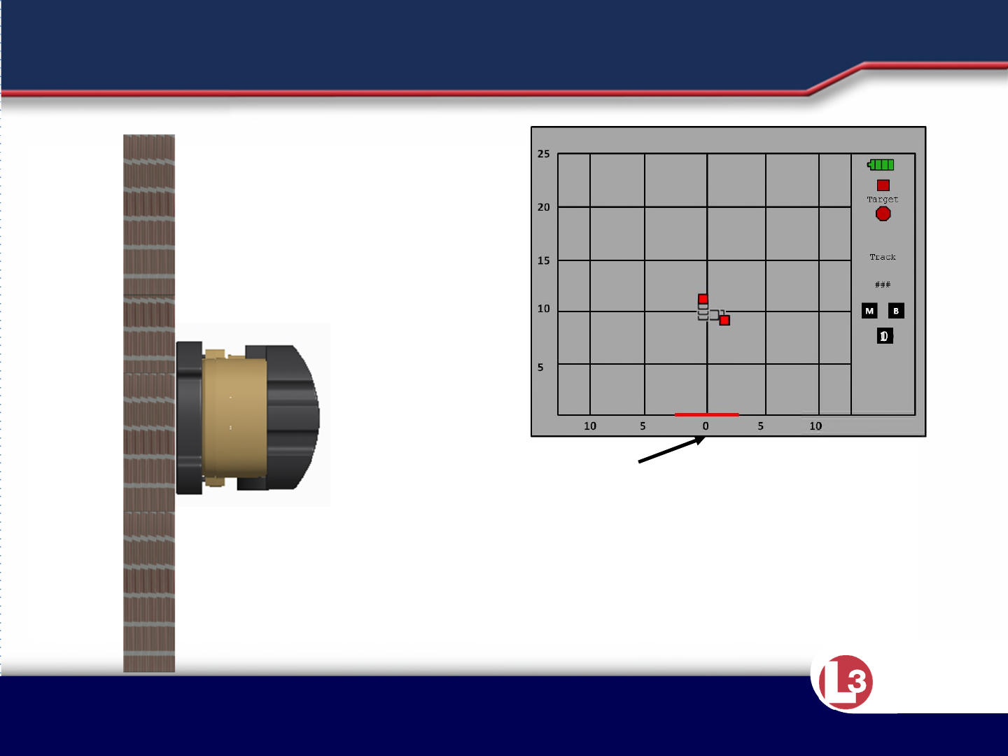
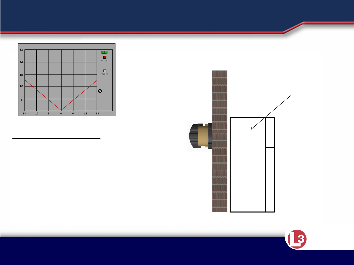
WALL COUPLING
Wall Mode is selected in the menu
screen and utilizes a 180 degree FOV.
The first wall always appears at the “0
line” when the system is set to Wall
mode, whether the system is against a
wall or not.

Approved for Public Release 20 October
2015 by U.S. Army Project Manager I2WD
10/9/2017 Approved for Public Release 20 October
2015 by U.S. Army Project Manager I2WD 31
CyTerra
SCAN TIMES
•The minimum amount of time to detect a stationary target
(standing person) is six seconds.
• There is a 2.5 second delay between the real movement and the
displayed results. The object is displayed where it was 2.5
seconds ago.
• Objects must be separated by at least 2 meters to be displayed
as separate targets.
A 30 second scan time is recommended before moving to a new
scanning position.
Factors to Consider When Gauging Scan Time
Approved for Public Release 20 October
2015 by U.S. Army Project Manager I2WD
10/9/2017 Approved for Public Release 20 October
2015 by U.S. Army Project Manager I2WD 32
CyTerra
CAPABILITIES
Detect Time ≈
30 Sec Detect Time ≈ 15 Sec
Detect
Time ≈
30 Sec
Detect Time ≈
5 Sec
Prone Seated
(min move)
Standing (min move)
Seated
(moving) Moving

Approved for Public Release 20 October
2015 by U.S. Army Project Manager I2WD
10/9/2017 Approved for Public Release 20 October
2015 by U.S. Army Project Manager I2WD 33
CyTerra
Brightness Adjustment
•The brightness level of the display is adjustable via a menu selection.
•To increase the brightness, select up and press the top scan button.
•To decrease the brightness, select down and press the top scan button.
•Orientation of the system does not affect the button use.
Zoom Feature and Adjustment
•The Zoom feature can only be accessed while in the Scan Mode. The top
and bottom scan buttons also control this function.
•The scan buttons allow the operator to zoom in or zoom out.
•Warning: The unit must settle for approximately 3-5 seconds after
scanning has started for the Zoom feature to work.
INSTRUCTION POINTS
Approved for Public Release 20 October
2015 by U.S. Army Project Manager I2WD
10/9/2017 Approved for Public Release 20 October
2015 by U.S. Army Project Manager I2WD 34
CyTerra
ADJUSTING SCREEN BRIGHTNESS
The brightness level is adjusted on the menu screen. The operator
Selects “up” or “down” to adjust the brightness of the screen.

Approved for Public Release 20 October
2015 by U.S. Army Project Manager I2WD
10/9/2017 Approved for Public Release 20 October
2015 by U.S. Army Project Manager I2WD 35
CyTerra
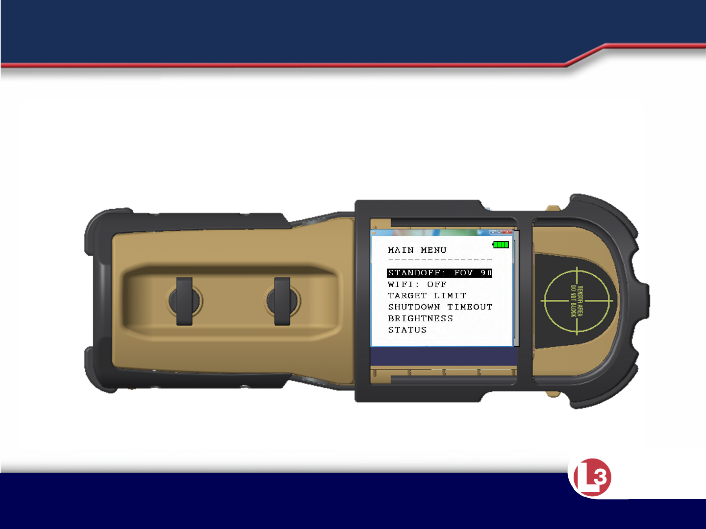
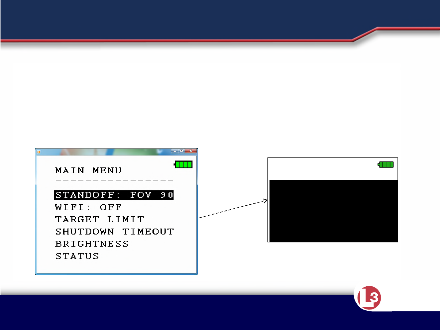
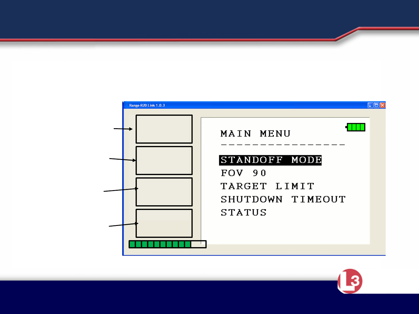
•By using the correct button sequence, the operator can navigate through
the four different menus . This allows the operator to customize the use of
the system. Once again, the Scan Buttons are used to navigate the menus
and make selections. The menus include the Main Menu, Standoff, Wifi,
Shutdown Timeout, Target Limit Select, Brightness and Status.
•Main Menu- allows operator to choose the other menu screens
–Note: Selection of Wall Mode or Standoff Mode is made on the Main Menu page. Field
of View (FOV) automatically changes to 180 (Wall Mode) or 90 (Standoff) with this mode
selection. Wifi on or off it the unit is a Range-R2D Link
•Target Limit Select- allows operator to limit the number of targets to be
displayed. Choices are 1, 2, 3, no limit.
•Shutdown Timeout- allows operator to select the time the system will stay
on without further button actuation
•Brightness – allows the operator to brighten or dim the display
•Status- shows system information
INSTRUCTION POINTS
Approved for Public Release 20 October
2015 by U.S. Army Project Manager I2WD
10/9/2017 Approved for Public Release 20 October
2015 by U.S. Army Project Manager I2WD 36
CyTerra
MAIN MENU
----------------
WALL MODE
FOV 180
TARGET LIMIT
SHUTDOWN TIMEOUT
BRIGHTNESS
STATUS
SHUTDOWN TIMEOUT
----------------
BACK
NO TIMEOUT
5 MINUTES*
10 MINUTES
MENU NAVIGATION
WALL MODE
FOV 90
TARGET LIMIT
• Press and release Scan Buttons to enter menu mode.
• Press and release the lower button to scroll through menu choices.
• Press and release the top button to make the selection.
• Currently selected options are noted by the *
• The example below shows selection of Shutdown Timeout
BACK
NO TIMEOUT
10 MINUTES
5 MINUTES*
This selection controls how long
the system will scan before
returning to standby mode.
SHUTDOWN TIMEOUT

Approved for Public Release 20 October
2015 by U.S. Army Project Manager I2WD
10/9/2017 Approved for Public Release 20 October
2015 by U.S. Army Project Manager I2WD 37
CyTerra
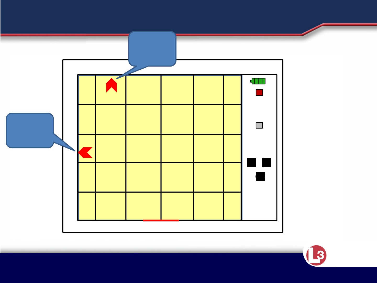
•The system allows changing the display to focus on an area
smaller than the default 25m range and azimuth.
Momentarily depressing the bottom button while in scan
mode changes to the 10m x 10m display, pressing it again
gives a 5m x 5m display.
•Depressing the upper button changes back to 10m x 10m, and
again changes back to the default display.
•Switching from scan back to standby restores the default
display.
•When in zoom mode, the display background changes to
yellow to alert the operator, and red arrows along the border
of the display indicate targets that are within the range of the
sensor, but beyond the selected display range.
DISPLAY ZOOM
Approved for Public Release 20 October
2015 by U.S. Army Project Manager I2WD
10/9/2017 Approved for Public Release 20 October
2015 by U.S. Army Project Manager I2WD 38
CyTerra
10m x 10m DISPLAY ZOOM
0
2
4 2 2 4
4
6
8
10
Target
Track
###
M B
01
Off Display
Target
Indicator
Off Display
Target
Indicator

Approved for Public Release 20 October
2015 by U.S. Army Project Manager I2WD
10/9/2017 Approved for Public Release 20 October
2015 by U.S. Army Project Manager I2WD 39
CyTerra
5m x 5m DISPLAY ZOOM
0
1
2 1 1 2
2
3
4
5
Target
Track
###
M B
01
Off Display
Target
Indicator
Off Display
Target
Indicator

Approved for Public Release 20 October
2015 by U.S. Army Project Manager I2WD
10/9/2017 Approved for Public Release 20 October
2015 by U.S. Army Project Manager I2WD 40
CyTerra
•Whenever the system is not functioning properly, yet is still able to boot
up, the message “RETURN TO DEPOT” will appear.
•If this happens, shutdown the system, wait 10 seconds, and restart the
system.
•Ensure the batteries are fully charged and installed properly.
•If the “RETURN TO DEPOT” message occurs again, the operator should
have the system serviced as soon as possible.
INSTRUCTION POINTS
Approved for Public Release 20 October
2015 by U.S. Army Project Manager I2WD
10/9/2017 Approved for Public Release 20 October
2015 by U.S. Army Project Manager I2WD 41
CyTerra
SYSTEM FAULT
RETURN TO DEPOT
•Shut down the sensor
•Power on the sensor
•If problem continues send for maintenance

Approved for Public Release 20 October
2015 by U.S. Army Project Manager I2WD
10/9/2017 Approved for Public Release 20 October
2015 by U.S. Army Project Manager I2WD 42
CyTerra
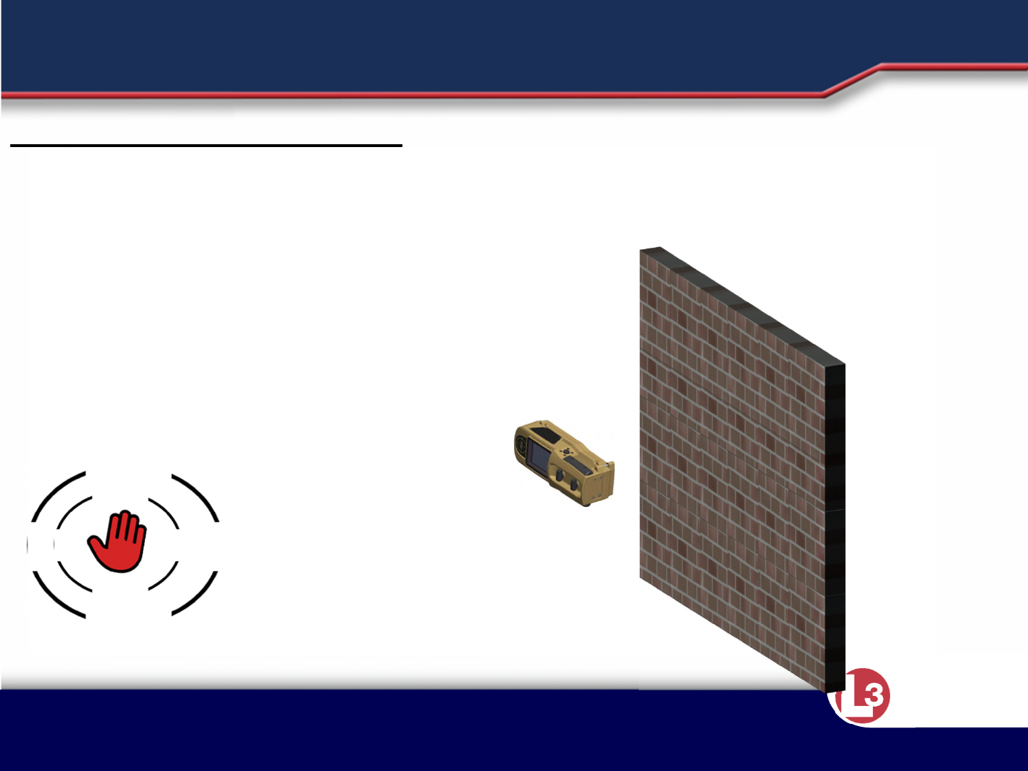
•Wall blockage occurs when a large reflective object obscures the view of the target
area. The reflective abject may be within the wall itself or in close proximity to the
wall. The RANGE-R2D sensor alerts the operator if such a condition exists.
•Since it is possible that the transmit signal is being blocked and not reaching
potential targets, target detection is not possible when blockage is detected.
•While operating in Scan Mode and with blockage detected, the word “Blocked”
will be displayed. If this occurs, the operator should move to a different spot on
the wall and try again.
•In some situations, a blockage alert indication may not occur even though the
signal is blocked. One such blockage could manifest if the system is held up directly
against a metal door or wall.
•In this situation, the transmit signal is completely blocked and little to no energy
reaches the receive antenna. Because the power threshold for a blockage signal
will not be exceeded, no alert is generated. Another scenario occurs when the wall
material is highly absorptive. Here, signal returns from the obscuring object are
greatly reduced by losses in the wall. The power threshold for a blockage signal is
not exceeded and no alert is generated.
INSTRUCTION POINTS

Approved for Public Release 20 October
2015 by U.S. Army Project Manager I2WD
10/9/2017 Approved for Public Release 20 October
2015 by U.S. Army Project Manager I2WD 43
CyTerra
FRONT BLOCKED
•Attempt to scan in a different area
•Consider construction materials
•Saturated, porous materials
•Metal
FRONT BLOCKED

Approved for Public Release 20 October
2015 by U.S. Army Project Manager I2WD
10/9/2017 Approved for Public Release 20 October
2015 by U.S. Army Project Manager I2WD 44
CyTerra
•There may also be cases where the system is receiving outside
interference causing it not to function as intended. In this case, the
message “JAMMED” will appear on the screen letting the operator know
there is a problem.
•While operating in Scan Mode and with strong interference detected, the
display will show the message “JAMMED”. Move to a different spot on the
wall where the interference may be lower. If the “JAMMED” indication
persists, the system cannot be used until the interference source ceases
operation.
•Multiple systems working in close proximity may cause the system to
display the “JAMMED” message.
INSTRUCTION POINTS
Approved for Public Release 20 October
2015 by U.S. Army Project Manager I2WD
10/9/2017 Approved for Public Release 20 October
2015 by U.S. Army Project Manager I2WD 45
CyTerra
JAMMED
•Outside interference is preventing scanning
•Consider other equipment being used by your unit
•Consider equipment being used by adjacent units
•Consider enemy/local capabilities
•Multiple systems working near each other
JAMMED

Approved for Public Release 20 October
2015 by U.S. Army Project Manager I2WD
10/9/2017 Approved for Public Release 20 October
2015 by U.S. Army Project Manager I2WD 46
CyTerra
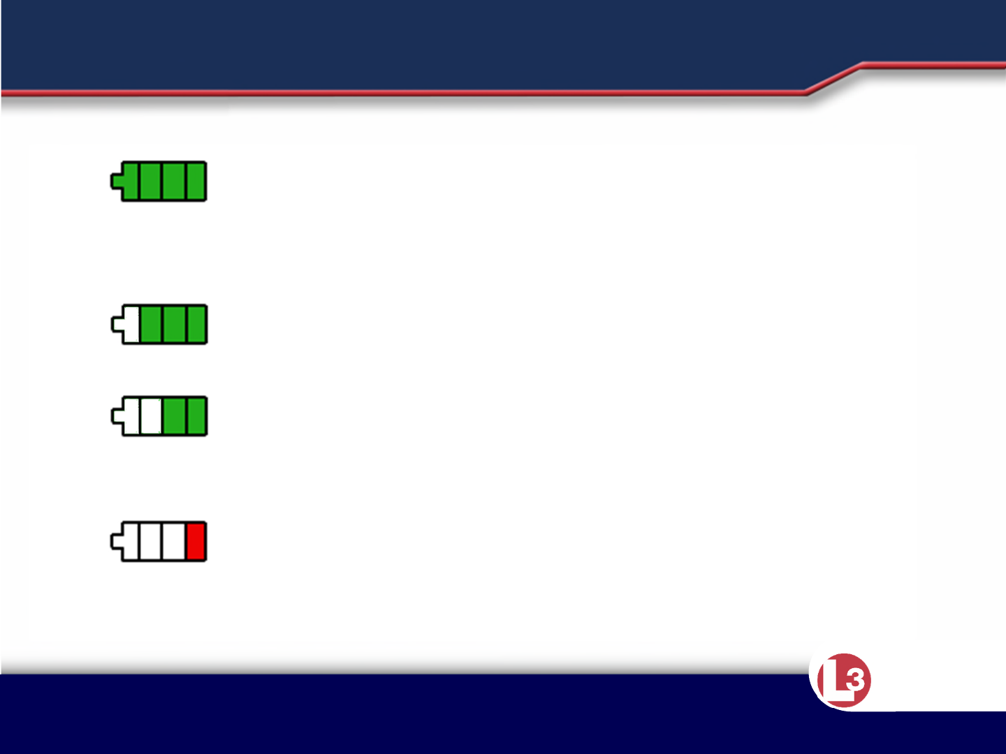
•Describe the different Battery Status Indicators
•FULL BATTERY – The battery voltage is sufficient to provide full operational
performance.
•LOW BATTERY CAUTION – The battery voltage is beginning to get low, but
will continue to function normally. The operator should consider replacing
the batteries when only 2 bars are illuminated.
•LOW BATTERY WARNING (Flashing) – The battery voltage is too low to
continue operation. The operator must replace the batteries. The sensor
will shut down 30 seconds after the flashing starts.
INSTRUCTION POINTS
Approved for Public Release 20 October
2015 by U.S. Army Project Manager I2WD
10/9/2017 Approved for Public Release 20 October
2015 by U.S. Army Project Manager I2WD 47
CyTerra
BATTERY STATUS INDICATORS
FULL BATTERY – The battery voltage is
sufficient to provide full operational
performance.
LOW BATTERY CAUTION – The battery
voltage is beginning to get low, but will
continue to function normally. The operator
should consider replacing the batteries
when only 2 bars are illuminated.
LOW BATTERY WARNING) – The battery
voltage is too low to continue operation.
The operator must replace the batteries.
Icon goes red with 30 minutes of battery
life, flashed at 30 seconds of life. The
system will shut down after 30 seconds.

Approved for Public Release 20 October
2015 by U.S. Army Project Manager I2WD
10/9/2017 Approved for Public Release 20 October
2015 by U.S. Army Project Manager I2WD 48
CyTerra
LESSON 3
Factors Affecting Detection

Approved for Public Release 20 October
2015 by U.S. Army Project Manager I2WD
10/9/2017 Approved for Public Release 20 October
2015 by U.S. Army Project Manager I2WD 49
CyTerra
The purpose of this section is to make the
user aware of phenomena that can affect the
performance of radar based sensors in
general, and phenomena that can affect the
RANGE-R2D specifically.
These phenomena do not affect every usage
of the sensor or every venue where it may be
used, but they are factors the operator needs
to be aware of to maximize the effectiveness
of the system.
USING A MOTION DETECTOR

Approved for Public Release 20 October
2015 by U.S. Army Project Manager I2WD
10/9/2017 Approved for Public Release 20 October
2015 by U.S. Army Project Manager I2WD 50
CyTerra
Factors that can cause unwanted detections (False
Alerts)
This is a motion detector. It will pick up the movement of any object. This
includes but is not limited to:
•Animals
•Friendly personnel (in front or behind the operator)
The system target acquisition algorithm is designed to negate the following,
but these items may still appear as targets:
•The movement of trees and foliage caused by the wind
•Oscillating fans (inconsistent circular patterns)
•Vibrating equipment (duct work, compressors, etc)
Any of these moving objects, and others, may appear as targets on the
display. There is no way for the operator to determine this “clutter” from an
actual target.
USING A MOTION DETECTOR

Approved for Public Release 20 October
2015 by U.S. Army Project Manager I2WD
10/9/2017 Approved for Public Release 20 October
2015 by U.S. Army Project Manager I2WD 51
CyTerra
Factors that can cause missed detections
Environmental factors can create a “noisy” Doppler environment and
can make it more difficult for the sensor to detect the targets of
interest:
•Ceiling fans can create a Doppler signal in their immediate vicinity of
greater strength than that of a stationary target, potentially causing the
target of interest in the same immediate vicinity to not be detected.
• RANGE-R2D looks for the unique ceiling fan signature and alerts the
operator that it’s present, indicates its location, and shows the
estimated area where detection may be affected as a shadowed area
on the display.
• Fluorescent lighting also creates a strong Doppler signature that can have
an effect more so on moving targets, if their movement speed aligns with a
Doppler frequency given off by the lights.
• RANGE-R2D looks for the signature emitted, and alerts the operator
to ensure they are aware reduced detection performance may occur.
USING A MOTION DETECTOR

Approved for Public Release 20 October
2015 by U.S. Army Project Manager I2WD
10/9/2017 Approved for Public Release 20 October
2015 by U.S. Army Project Manager I2WD 52
CyTerra
•Radar will not penetrate metallic surfaces. Should you try to scan over a
metallic surface the “Blocked” screen appears. In this instance you should
attempt to rescan in an attempt to find a less metallic area.
•Metal plate is the most likely to give you problems.
•The sensor will be able to “see” through rebar reinforced concrete.
INSTRUCTION POINTS
Approved for Public Release 20 October
2015 by U.S. Army Project Manager I2WD
10/9/2017 Approved for Public Release 20 October
2015 by U.S. Army Project Manager I2WD 53
CyTerra
BUILDING MATERIALS
Metallic Surfaces and Objects
• Sensor can not penetrate metal
surfaces
• Move sensor and attempt to
rescan
• Metallic surfaces behind non-
metallic surfaces could also block
the system (refrigerator, file
cabinet).
FRONT BLOCKED
Approved for Public Release 20 October
2015 by U.S. Army Project Manager I2WD
10/9/2017 Approved for Public Release 20 October
2015 by U.S. Army Project Manager I2WD 54
CyTerra
UNDETECTED FRONT BLOCK
Unseen obstructions
• Metal objects behind the wall can
block the signal from the radar.
• Because there is space between
the system and the metal, the
blocked warning may not be
detected.
Refrigerator/filing
cabinets
Approved for Public Release 20 October
2015 by U.S. Army Project Manager I2WD
10/9/2017 Approved for Public Release 20 October
2015 by U.S. Army Project Manager I2WD 55
CyTerra
Scanning with the system
between two blocks may
reduce the effectiveness of the
system.
Attempt to scan with the system
over one block only.
Concrete Block
The spaces in concrete block walls can cause some
reduction in detection ability
BUILDING MATERIALS
Approved for Public Release 20 October
2015 by U.S. Army Project Manager I2WD
10/9/2017 Approved for Public Release 20 October
2015 by U.S. Army Project Manager I2WD 56
CyTerra
BUILDING MATERIALS
Moisture content
of the structure
being scanned will
affect the systems
ability to “see”
through the walls.
If the surface is
saturated, the
system may not
be able to detect
targets at all. The amount of
moisture will affect the
systems detection
capability. The more
moisture present, the
less detection
capability is available.
Approved for Public Release 20 October
2015 by U.S. Army Project Manager I2WD
10/9/2017 Approved for Public Release 20 October
2015 by U.S. Army Project Manager I2WD 57
CyTerra
When scanning against
the wall, ensure that
system is flush to the
surface being scanned
and being held to eye
level.
Begin scanning only
after you have set the
system in place.
OPERATOR INDUCED ERRORS
Approved for Public Release 20 October
2015 by U.S. Army Project Manager I2WD
10/9/2017 Approved for Public Release 20 October
2015 by U.S. Army Project Manager I2WD 58
CyTerra
As the operator you can diminish the systems ability to detect objects. The system
should be held so the operator’s hands do not interfere with any of the system’s
antennas.
Do not block the rearward
looking antenna. Do not block the front looking
antennas.
OPERATOR INDUCED ERRORS
RANGE-R2D
Bumpers removed for
clarity

Approved for Public Release 20 October
2015 by U.S. Army Project Manager I2WD
10/9/2017 Approved for Public Release 20 October
2015 by U.S. Army Project Manager I2WD 59
CyTerra
•Movement from the operator, teammates, and the operator moving the
sensor itself can all affect what is/isn’t detected by the system. The
movement indicator on the bottom right corner of the LCD lets the
operator know if he/she is moving the sensor enough to affect detection.
•The sensor should be kept as still as possible when scanning.
•As mentioned earlier DO NOT BLOCK THE REARWARD FACING ANTENNA
when trying to stabilize the system.
INSTRUCTION POINTS
Approved for Public Release 20 October
2015 by U.S. Army Project Manager I2WD
10/9/2017 Approved for Public Release 20 October
2015 by U.S. Army Project Manager I2WD 60
CyTerra
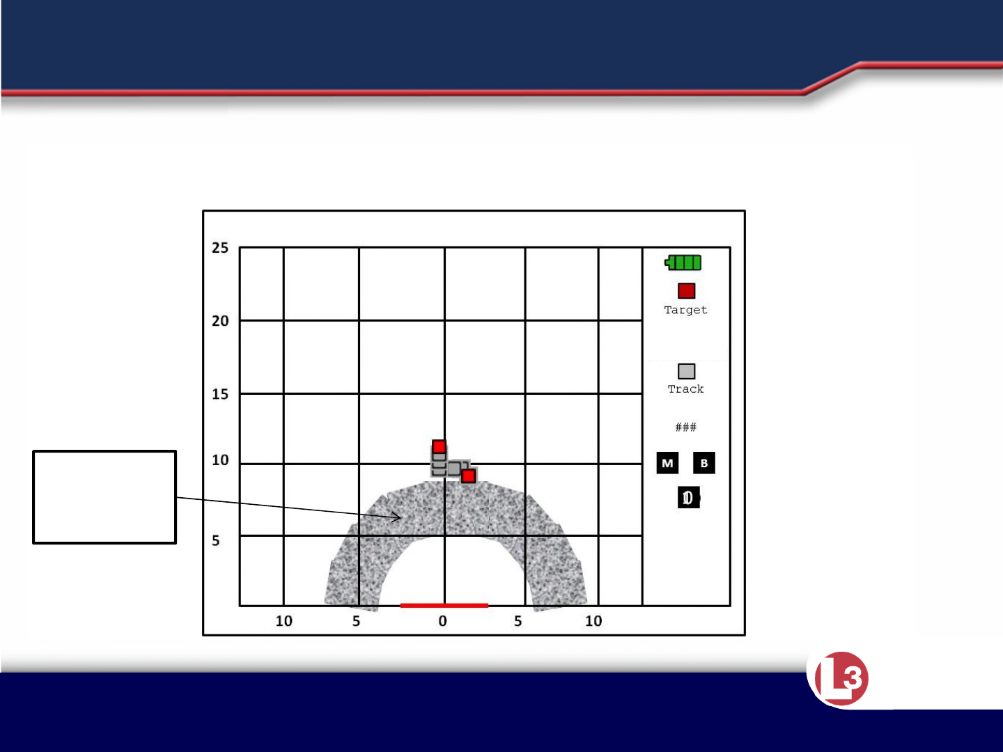
•The sensor will also indicate areas of possible reduced detection by
showing those areas as shaded on the display.
INSTRUCTION POINTS
Area of
Reduced
Detection
Approved for Public Release 20 October
2015 by U.S. Army Project Manager I2WD
10/9/2017 Approved for Public Release 20 October
2015 by U.S. Army Project Manager I2WD 61
CyTerra
•The movement from ceiling fans can cause the noise level the radar sees
to be too high for stationary target detection in the area under and
adjacent to the fan. The RANGE-R2D can detect the unique signature of a
ceiling fan and will show the operator where it’s located so they can be
aware of the area of reduced detection.
INSTRUCTION POINTS
Area of
Reduced
Detection
Approved for Public Release 20 October
2015 by U.S. Army Project Manager I2WD
10/9/2017 Approved for Public Release 20 October
2015 by U.S. Army Project Manager I2WD 62
CyTerra
•The movement from ceiling fans can cause the noise level the radar sees to be too
high for stationary target detection in the area under and adjacent to the fan. The
RANGE-R2D can detect the unique signature of a ceiling fan and will show the
operator where it’s located so they can be aware of the area of reduced detection.
INSTRUCTION POINTS
Area of
Reduced
Detection
0
5
10 5 5 10
10
15
20
25
Target
Track
###
M B
01
Approved for Public Release 20 October
2015 by U.S. Army Project Manager I2WD
10/9/2017 Approved for Public Release 20 October
2015 by U.S. Army Project Manager I2WD 63
CyTerra
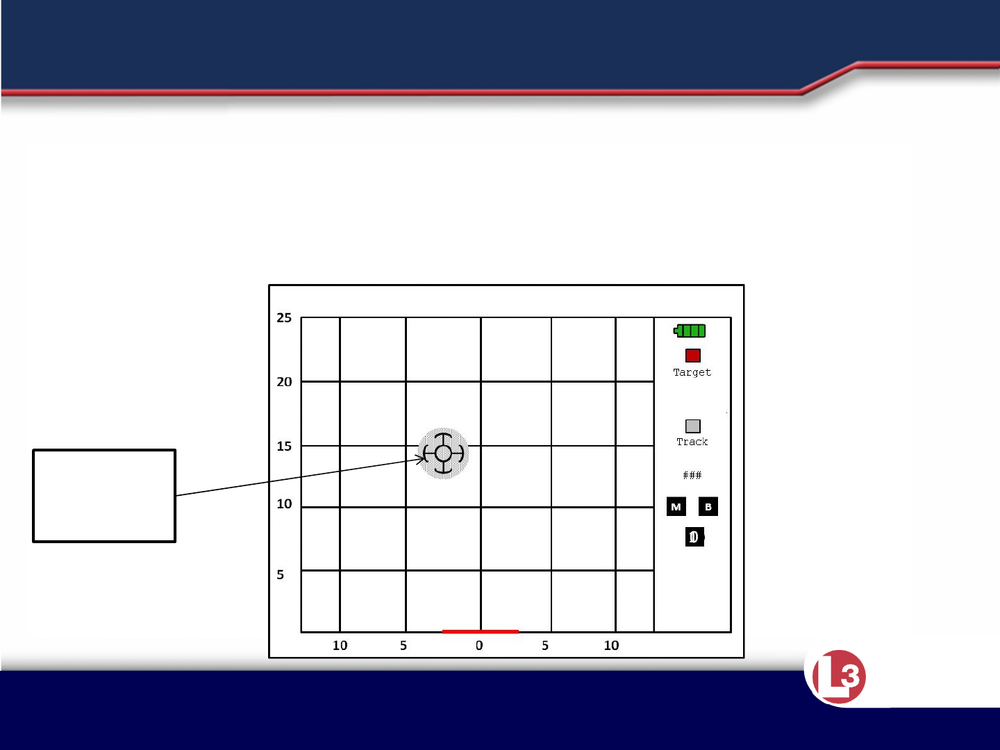
•The electronic signature emitted by fluorescent lighting can cause areas of
reduced detection. The RANGE-R2D can detect the unique signature of fluorescent
lights and it alerts the operator that it’s present and detection may be reduced.
INSTRUCTION POINTS
0
5
10 5 5 10
10
15
20
25
Target
Track
###
M B
01
FLUOR
Approved for Public Release 20 October
2015 by U.S. Army Project Manager I2WD
10/9/2017 Approved for Public Release 20 October
2015 by U.S. Army Project Manager I2WD 64
CyTerra
Operators Effect on the System:
The operator should remain as still as possible. This is especially important
when the sensor is being used in standoff from a wall. The system will display
no new information while the Operator Movement Indicator is displayed.
Operator
Movement
Indicator
OPERATOR INDUCED ERRORS
If the Operator Movement Indicator
appears, first attempt to stabilize
the system.
If the indicator persists, attempt to
rescan.

Approved for Public Release 20 October
2015 by U.S. Army Project Manager I2WD
10/9/2017 Approved for Public Release 20 October
2015 by U.S. Army Project Manager I2WD 65
CyTerra
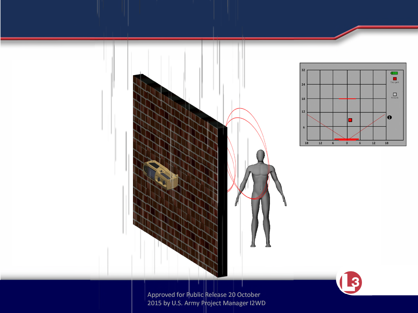
•Part of the radar energy emitted by the sensor penetrates the building and part
reflects off the building back in the direction of the sensor.
•The energy reflected off the building can reflect off moving objects behind the
sensor and back to the sensor in a path makes movement behind the sensor
look like it is actually in front of it.
•If the movement behind the sensor is at the same range as the target inside the
building is from the first wall of the building, this energy competes with the
energy of the target.
•The more closely grouped personnel are to the sensor, the smaller the area
affected by their movement.
•The sensor has a rear looking antenna and software algorithms that detect
movement behind the sensor and remove the unwanted energy, but if the
backside energy is much greater than the target energy, the target may be
cancelled also.
•The operator and any personnel behind the sensor should remain still during
scanning.
INSTRUCTION POINTS
Approved for Public Release 20 October
2015 by U.S. Army Project Manager I2WD
10/9/2017 Approved for Public Release 20 October
2015 by U.S. Army Project Manager I2WD 66
CyTerra
BACKSIDE TARGETS
WARNING
The energy from personnel moving
behind the sensor may prevent
detection of targets
To help prevent this, the system will
warn you that there is too much motion
being detected on the operator’s side
of the system by displaying the
Excessive Backside Motion Icon.
10m
0m
5m
5m
1
In some cases the
Backside Motion Indicator
will not appear and
backside targets could
appear as targets in your
target area.
BACK
MOTION

Approved for Public Release 20 October
2015 by U.S. Army Project Manager I2WD
10/9/2017 Approved for Public Release 20 October
2015 by U.S. Army Project Manager I2WD 67
CyTerra
REDUCED BACKSIDE DETECTION
The operator may reduce the effectiveness of
the rearward looking antenna’s ability to
reduce backside motion if the antenna is
blocked by the operators body
No reduction No reduction
This reduced area will move
based on how the system is
held by the operator
Operator
Reduced due
to operator
interference.

Approved for Public Release 20 October
2015 by U.S. Army Project Manager I2WD
10/9/2017 Approved for Public Release 20 October
2015 by U.S. Army Project Manager I2WD 68
CyTerra
•Part of the radar energy emitted by the sensor penetrates the building and part
reflects off the building back in the direction of the sensor.
•The energy reflected off the building can reflect off moving objects behind the
sensor and back to the sensor in a path makes movement behind the sensor
look like it is actually in front of it.
•If the movement behind the sensor is at the same range as the target inside the
building is from the first wall of the building, this energy competes with the
energy of the target.
•The more closely grouped personnel are to the sensor, the smaller the area
affected by their movement.
•The sensor has a rear looking antenna and software algorithms that detect
movement behind the sensor and remove the unwanted energy, but if the
backside energy is much greater than the target energy, the target may be
cancelled also.
•The operator and any personnel behind the sensor should remain still during
scanning.
INSTRUCTION POINTS
Approved for Public Release 20 October
2015 by U.S. Army Project Manager I2WD
10/9/2017 Approved for Public Release 20 October
2015 by U.S. Army Project Manager I2WD 69
CyTerra
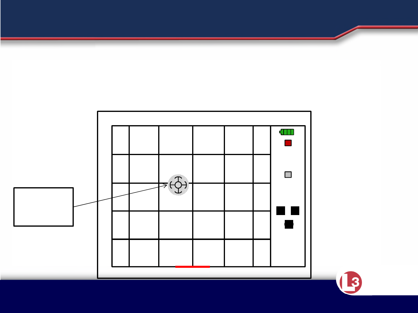
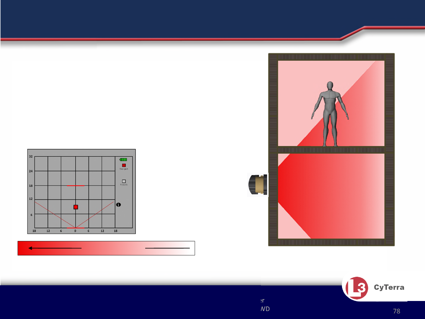
• The sensor detects
backside motion and
indicates the area in
the field of view that
may be impacted by
shading that area on
the display.
18m
1
ENVIRONMENTAL TARGET MASKING
Approved for Public Release 20 October
2015 by U.S. Army Project Manager I2WD
10/9/2017 Approved for Public Release 20 October
2015 by U.S. Army Project Manager I2WD 70
CyTerra
1
Targets may be too close
to be represented by
individual target icons.
The multi target icon (red
square) is used in these
situations.
0 55
MULTIPLE TARGETS
2
05 1010 5
5
10
15
20
Approved for Public Release 20 October
2015 by U.S. Army Project Manager I2WD
10/9/2017 Approved for Public Release 20 October
2015 by U.S. Army Project Manager I2WD 71
CyTerra
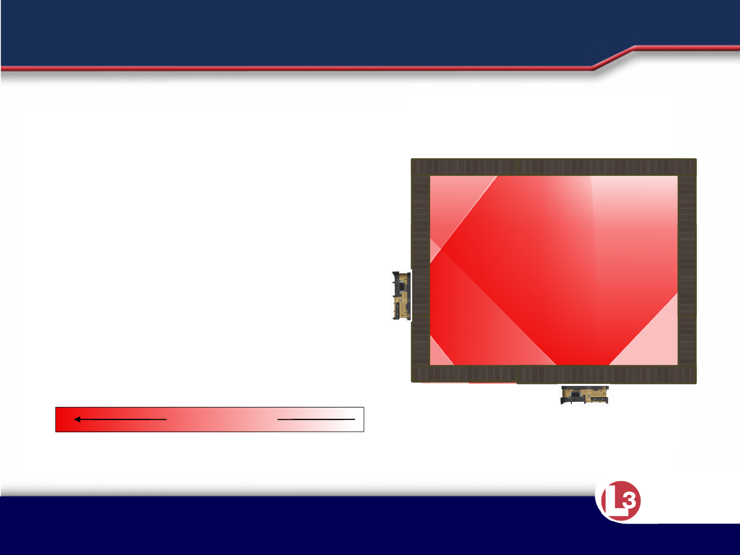
Larger targets may appear to travel in an arc when they pass in front of the system. This
is because of their large radar cross section.
LARGE TARGETS

Approved for Public Release 20 October
2015 by U.S. Army Project Manager I2WD
10/9/2017 Approved for Public Release 20 October
2015 by U.S. Army Project Manager I2WD 72
CyTerra
•The best detection performance occurs directly in front of the unit, and
extends out ±60 degrees in a conical pattern.
•The detection performance rapidly falls off to a minimum at ±90 degrees,
creating blind spots. Detection is possible within these blind spots, but
will be greatly reduced.
•The optimal detection distance is a maximum of 25 meters but this may
vary based on the type of wall construction.
•Detection through multiple walls or even an entire building is possible
depending on the construction materials of the wall within the structure,
however detection performance is diminished when traveling through
additional walls such as interior cinder block or concrete walls.
•Stationary targets detection will diminish more rapidly than moving target
detection.
•The sensor always assumes it is against the wall of the structure and
shows the first wall at zero range. The 2nd wall is shown at the distance
estimated by the sensor.
INSTRUCTION POINTS
Approved for Public Release 20 October
2015 by U.S. Army Project Manager I2WD
10/9/2017 Approved for Public Release 20 October
2015 by U.S. Army Project Manager I2WD 73
CyTerra
25 meters
Probability of Detection
More Likely
The best detection performance
occurs directly in front of the
unit, and extends out ±60
degrees in a conical pattern.
Detection performance rapidly
falls off to a minimum at ±90
degrees, creating blind spots.
Detection performance may be
diminished because of
construction material and the
number of walls in the detection
range.
Areas of Reduced Accuracy in the Field
of View.
FACTORS EFFECTING DETECTION
120°

Approved for Public Release 20 October
2015 by U.S. Army Project Manager I2WD
10/9/2017 Approved for Public Release 20 October
2015 by U.S. Army Project Manager I2WD 74
CyTerra
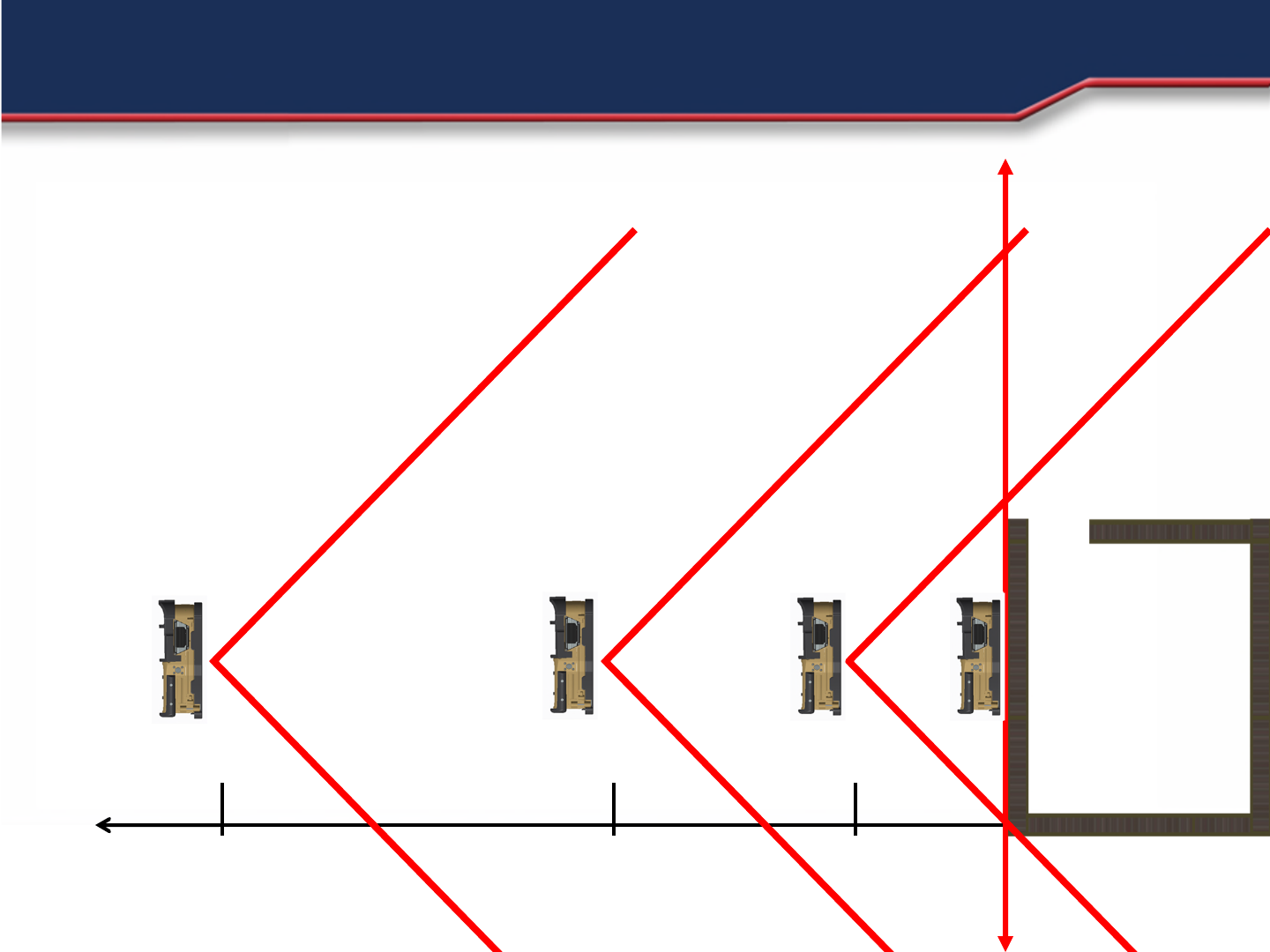
•Multiple scans performed at set intervals along the wall or adjacent walls
of the same room will increase area coverage and increase your
probability of detecting targets.
•By performing these extra scans, the amount of area with diminished
detection performance is drastically reduced.
•The number and amount of times scanned will be determined by the
operator.
INSTRUCTION POINTS
Approved for Public Release 20 October
2015 by U.S. Army Project Manager I2WD
10/9/2017 Approved for Public Release 20 October
2015 by U.S. Army Project Manager I2WD 75
CyTerra
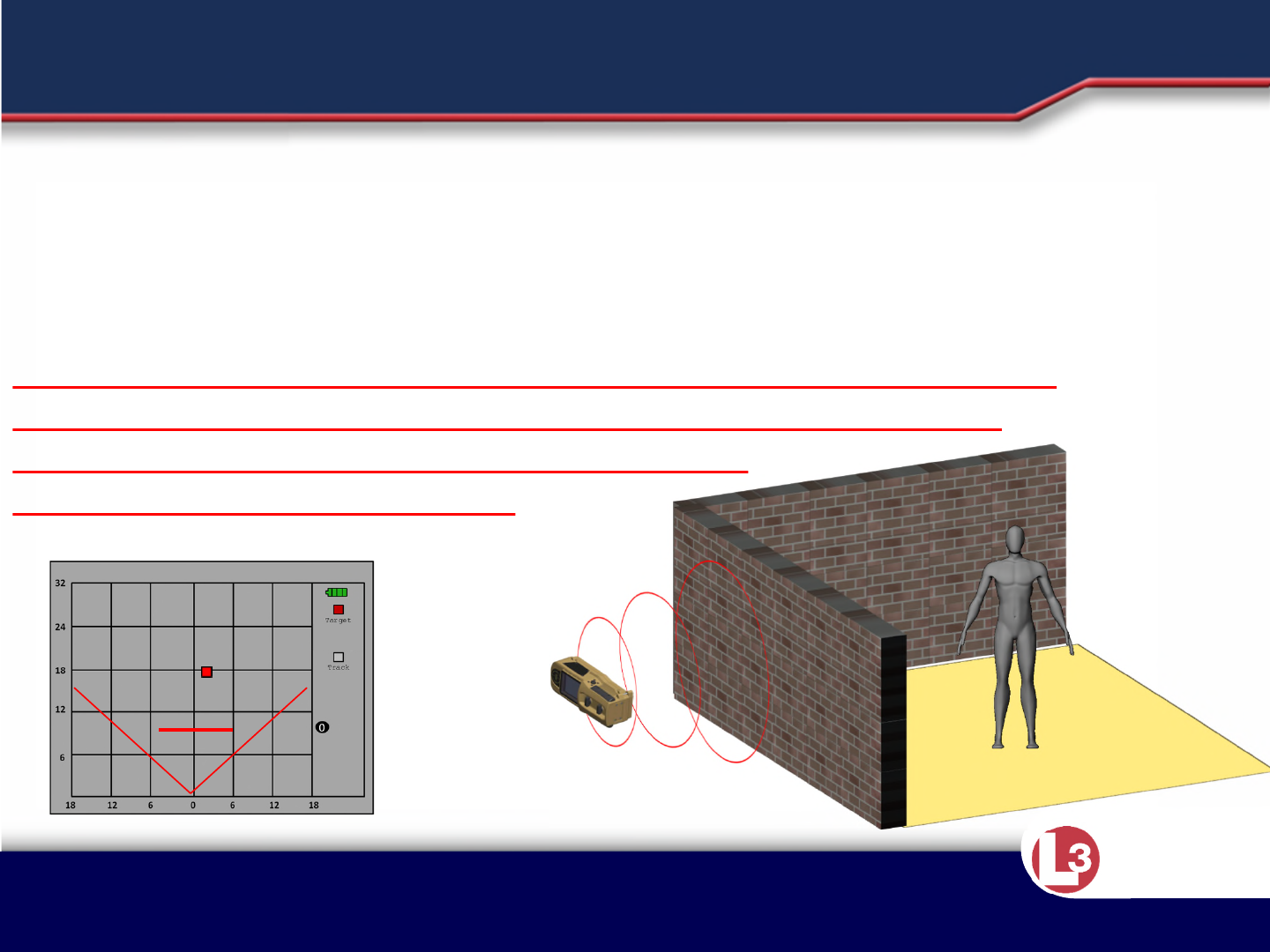
•Walls less than one meter apart will
not be counted as two walls.
•If the second wall is greater than 10
meters away it will not be displayed
on the readout
18 m
WALL DETECTION
Approved for Public Release 20 October
2015 by U.S. Army Project Manager I2WD
10/9/2017 Approved for Public Release 20 October
2015 by U.S. Army Project Manager I2WD 76
CyTerra
Multiple scans performed at
set intervals along the wall or
adjacent walls of the same
room will increase area
coverage and increase your
probability of detecting
targets.
Probability of Detection
More Likely
Area Coverage.
FACTORS AFFECTING DETECTION

Approved for Public Release 20 October
2015 by U.S. Army Project Manager I2WD
10/9/2017 Approved for Public Release 20 October
2015 by U.S. Army Project Manager I2WD 77
CyTerra
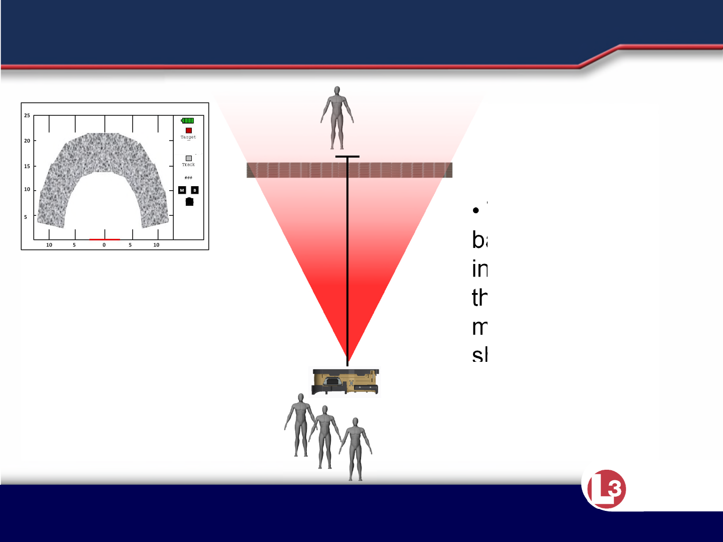
•The RANGE-R2D is also capable of detecting targets on different floors
within a building if the targets falls within the field of view of the system.
•Operators will not be able to determine precisely which floor is producing
the alert.
•Detection performance may diminish when travelling through the ceiling
or the floor of the structure based upon types of material encountered.
INSTRUCTION POINTS
Approved for Public Release 20 October
2015 by U.S. Army Project Manager I2WD
10/9/2017 Approved for Public Release 20 October
2015 by U.S. Army Project Manager I2WD 78
CyTerra
Probability of Detection
More Likely
When scanning a multiple level
structure, personnel on different levels
may be detected if the target is within
the field of view of the system.
Two Story Building
Multi-level Structures.
FACTORS EFFECTING DETECTION
Approved for Public Release 20 October
2015 by U.S. Army Project Manager I2WD
10/9/2017 Approved for Public Release 20 October
2015 by U.S. Army Project Manager I2WD 79
CyTerra
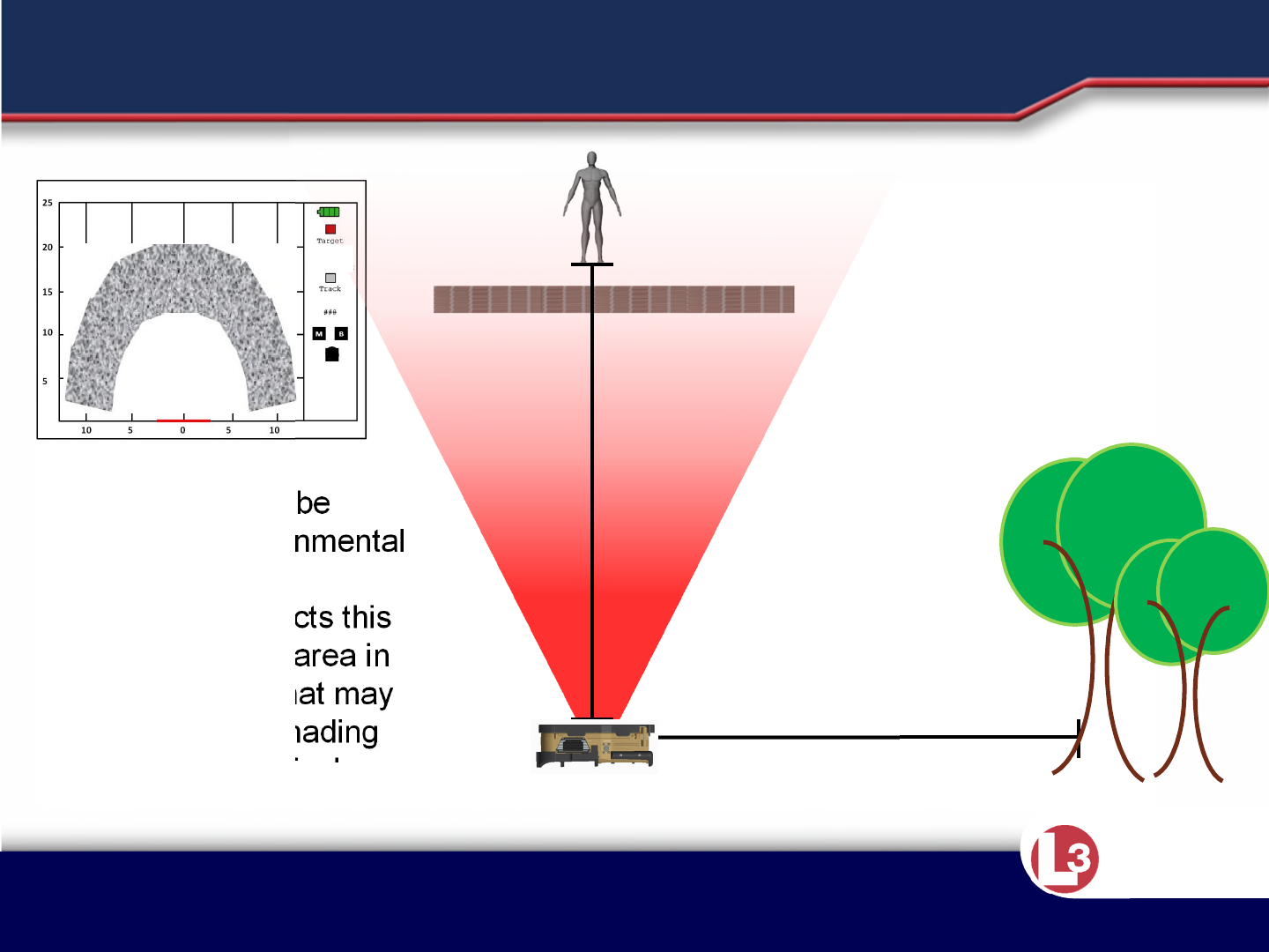
18m
• Breathers could be
masked by environmental
factors.
• The sensor detects this
and indicates the area in
the field of view that may
be impacted by shading
that area on the display.
18m
1
ENVIRONMENTAL TARGET MASKING

Approved for Public Release 20 October
2015 by U.S. Army Project Manager I2WD
10/9/2017 Approved for Public Release 20 October
2015 by U.S. Army Project Manager I2WD 80
CyTerra
•If necessary or desired, the system can be used in standoff away from a
wall. The system will still display the first two walls within detection range.
Keep in mind that the systems range is still 25 meters. If the system is held
10 meters from a wall you will only be able to detect 15 meters past that
wall.
•Using the system from a standoff position will be more difficult than
operating the system against the wall. The operator must do his best to
keep the system steady. The system must be mounted to a tripod for best
results. A monopod may be used, but stationary target detection
sensitivity may be reduced. If the system is moving too much, the “shaky
hand” movement indicator will be displayed on the bottom right hand of
the display.
•The sights on the outside of the system above the display (in either left or
right handed use) can be used to aim at specific points. The sights are off
set from the display opening to ensure that they line up with the center of
the actual radar display.
INSTRUCTION POINTS
Approved for Public Release 20 October
2015 by U.S. Army Project Manager I2WD
10/9/2017 Approved for Public Release 20 October
2015 by U.S. Army Project Manager I2WD 81
CyTerra
SCANNING WITH STANDOFF
It is possible for the system to be used away from walls or surfaces
to detect targets.
Ensure the distance from the first wall is greater than ½ meter.
Detection of the first wall is critical to operation of the sensor. If the
first wall is not shown at correct approximate location, move the
sensor enough to bring up the motion indicator.
This will reinitiate wall detection.
Approved for Public Release 20 October
2015 by U.S. Army Project Manager I2WD
10/9/2017 Approved for Public Release 20 October
2015 by U.S. Army Project Manager I2WD 82
CyTerra
NARROWED FIELD OF VIEW
To help reduce the risk of false
positives when set to Standoff mode,
the system will adjust it’s field of view
to 90 degrees. (Field of view is 180
degrees when set to Wall mode.)
0m10m
15m 5m
90° 90° 90° 180°
Approved for Public Release 20 October
2015 by U.S. Army Project Manager I2WD
10/9/2017 Approved for Public Release 20 October
2015 by U.S. Army Project Manager I2WD 83
CyTerra
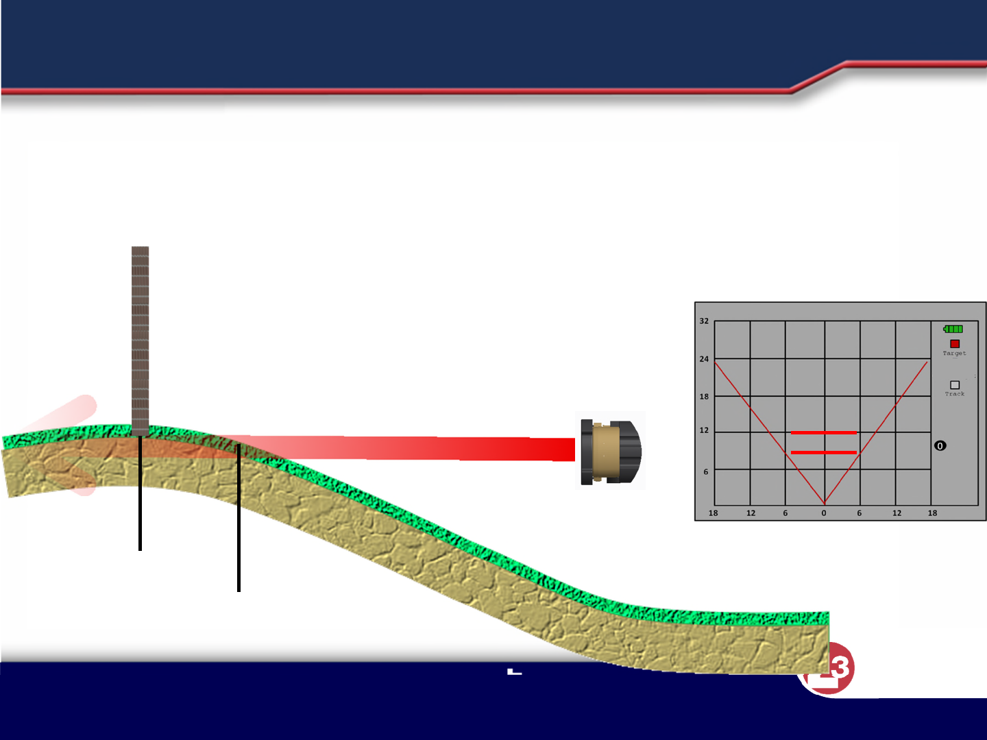
9
meters
12
meters
Aim the system at the structure you intend to
scan. Just keeping the system “level” can result in
the ground being interpreted as a wall by the
system.
SCANNING WITH STANDOFF
Approved for Public Release 20 October
2015 by U.S. Army Project Manager I2WD
10/9/2017 Approved for Public Release 20 October
2015 by U.S. Army Project Manager I2WD 84
CyTerra
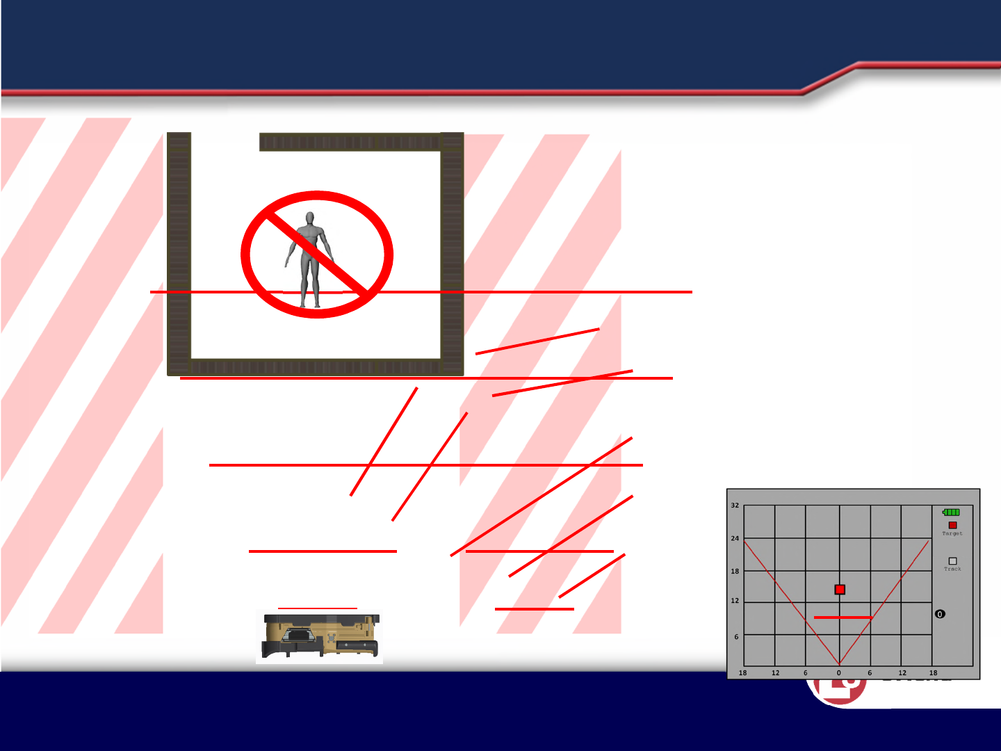
Scanning from the corners
or off angles can reduce the
effectiveness of the system.
SCANNING WITH STANDOFF
When scanning in standoff
mode it is important to be
center the system to the
structure you are scanning.
If you are not centered on the
structure when scanning, the
first wall may not be detected
giving you inaccurate
readings while scanning

Approved for Public Release 20 October
2015 by U.S. Army Project Manager I2WD
10/9/2017 Approved for Public Release 20 October
2015 by U.S. Army Project Manager I2WD 85
CyTerra
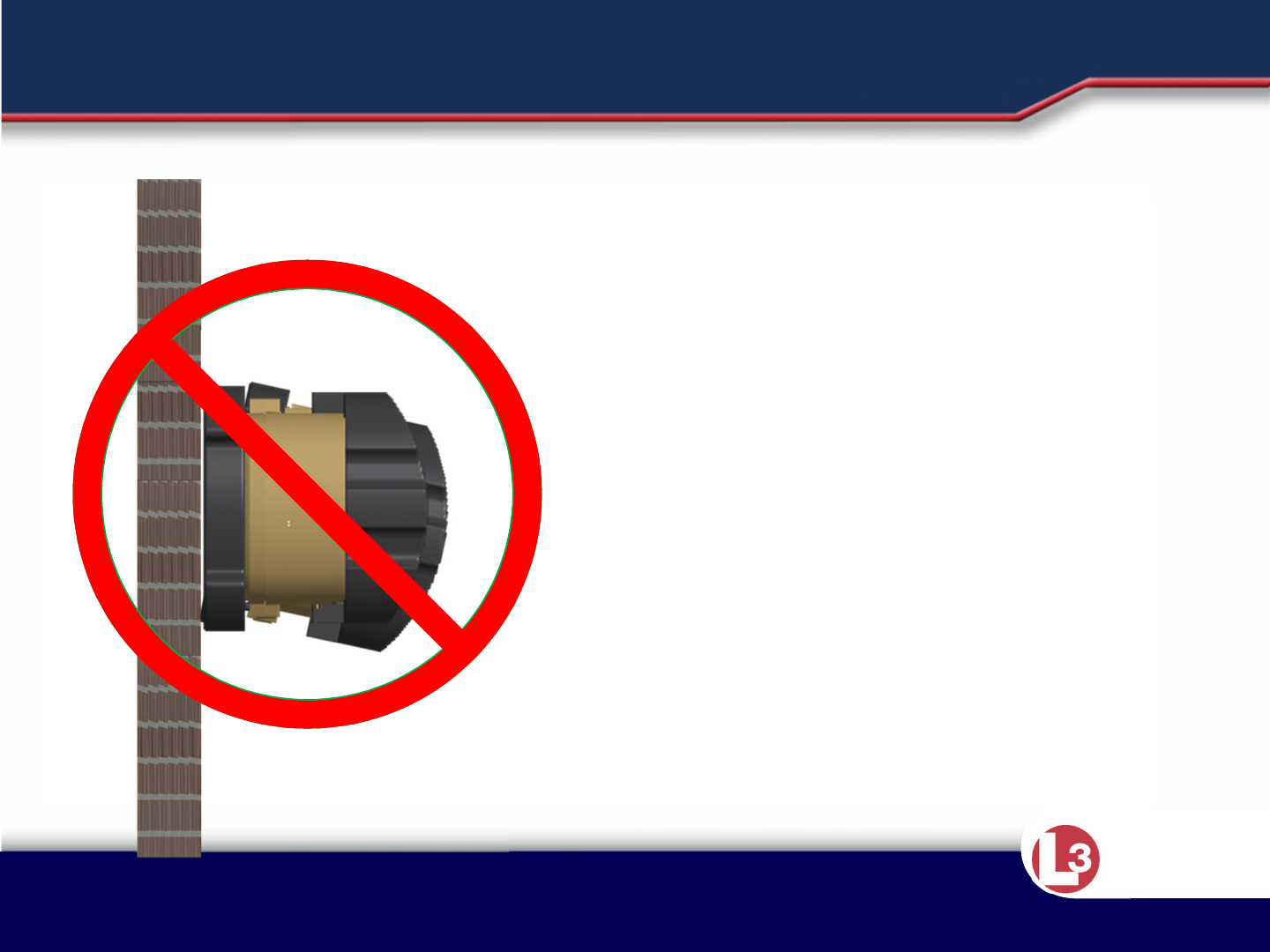
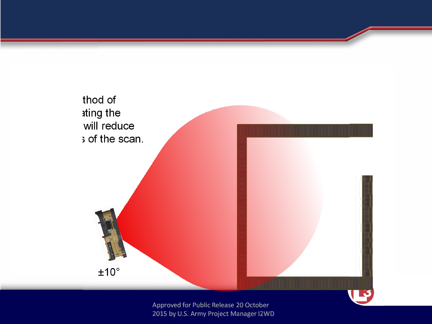
• While not the ideal method of operation, the system can be used +/- 10°
from parallel of the wall being scanned.
• Using the sensor at a greater angle than 10˚ from the wall may cause
degradation of detection of walls and negatively affect detection of targets.
INSTRUCTION POINTS
Approved for Public Release 20 October
2015 by U.S. Army Project Manager I2WD
10/9/2017 Approved for Public Release 20 October
2015 by U.S. Army Project Manager I2WD 86
CyTerra
Off-Angle Use
Not the ideal method of
operation. Operating the
system this way will reduce
the effectiveness of the scan.
±10°
SCANNING WITH STANDOFF
Approved for Public Release 20 October
2015 by U.S. Army Project Manager I2WD
CyTerra
RANGE-R2D LINK
ADDENDUM TO RANGE-R2D
OPERATION &TRAINING MANUAL

Approved for Public Release 20 October
2015 by U.S. Army Project Manager I2WD
CyTerra
FCC Required Information
•Warning: Changes or modifications to this device not expressly approved by L-3 CyTerra could void the
user’s authority to operate the equipment
•NOTE: This equipment has been tested and found to comply with the limits for a Class B digital device,
pursuant to Part 15 of the FCC Rules. These limits are designed to provide reasonable protection against
harmful interference in a residential installation. This equipment generates, uses, and can radiate radio
frequency energy and, if not installed and used in accordance with the instructions, may cause harmful
interference to radio communications. However, there is no guarantee that interference will not occur in a
particular installation. If this equipment does cause harmful interference to radio or television reception,
which can be determined by turning the equipment off and on, the user is encouraged to try to correct the
interference by one or more of the following measures:
–Reorient or relocate the receiving antenna.
–Increase the separation between the equipment and receiver.
–Connect the equipment into an outlet on a circuit different from that to which the receiver is connected.
–Consult the dealer or an experienced radio/TV technician for help.
•This equipment complies with radiation exposure limits set forth for an uncontrolled environment. This
equipment is in direct contact with the body of the user under normal operating conditions. This
transmitter must not be co-located or operating in conjunction with any other antenna or transmitter.

Approved for Public Release 20 October
2015 by U.S. Army Project Manager I2WD
CyTerra
LESSON 1
Description and Capabilities

Approved for Public Release 20 October
2015 by U.S. Army Project Manager I2WD
CyTerra
INSTRUCTION POINTS
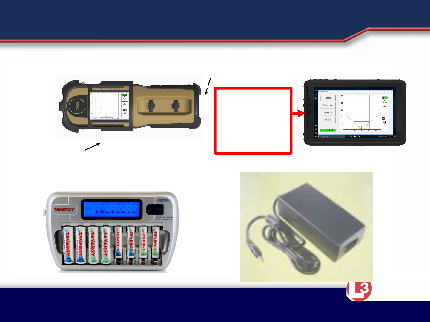
•The RANGE-R2D LINK system is RANGE-R2D with secure WiFi capability
added that allows remote monitoring and control of the system from a
distance of 100 meters or greater (Line of Sight).
•The 2D LINK system can also operate from AC power with the provided
power supply.
•Components of the RANGE-R2D LINK System
–RANGE-R2D LINK sensor with built in WiFi module and tripod mount.
–HP Stream 7 (or equivalent) Windows Tablet ( Do Not cover upper left corner, this is
where the antennae is located)
–AC power supply and cord (used for either the sensor or the battery charger).
–Qty. 16 nickel metal hydride rechargeable batteries
–8 cell battery charger.
Approved for Public Release 20 October
2015 by U.S. Army Project Manager I2WD
CyTerra
MAJOR COMPONENTS
WiFi Module
RANGE-R2D LINK REMOTE DEVICE
BATTERY CHARGER POWER SUPPLY
Tripod Mount Note: Do not cover Remote
Device Antennae
WIFI
ANTENNAS!
Keep hands
away from this
edge for best
results.
Approved for Public Release 20 October
2015 by U.S. Army Project Manager I2WD
CyTerra
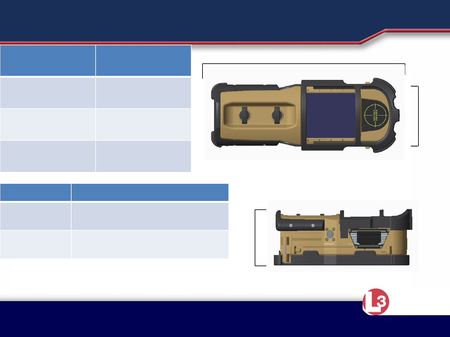
Item Dimensions
RANGE-R2D
Link Unit 12”x3.6”x3.9”
(25.4cm x 9.14cm x 9.91cm)
Storage
Container 16.3”x12.8”x6.8”
(41.4cm x 32.51cm x 17.27cm)
11”
4”
4”
MECHANICAL DATA
Item Weight
RANGE-R2D Link
Unit 3.5 lbs
(1.36 kg)
Storage Container 6.1 lbs
(2.77 kg)
Soft Case 0.5 lbs
(0.23 kg)

Approved for Public Release 20 October
2015 by U.S. Army Project Manager I2WD
CyTerra
LESSON 2
Operation
Approved for Public Release 20 October
2015 by U.S. Army Project Manager I2WD
CyTerra
POWERING THE SYSTEM
•The RANGE-R2D LINK can operate from either Lithium Energizer L91
primary batteries, rechargeable nickel metal hydride batteries, or external
AC power supply.
–Install the desired batteries or connect the external power supply to the external power
connector.
–CAUTION! DO NOT INSTALL BATTERIES AND CONNECT THE EXTERNAL POWER SUPPLY
SIMUTANEOUSLY AS THE POWER SUPPLY WILL BE SUPPLYING UNREGULATED CURRENT
TO THE BATTERIES AND DAMAGE TO THE BATTERIES, POWER SUPPLY AND/OR RANGE-
R2D LINK SENSOR MAY OCCUR!
WiFi Module
RANGE-R2D LINK
External Power
Connector
Approved for Public Release 20 October
2015 by U.S. Army Project Manager I2WD
CyTerra
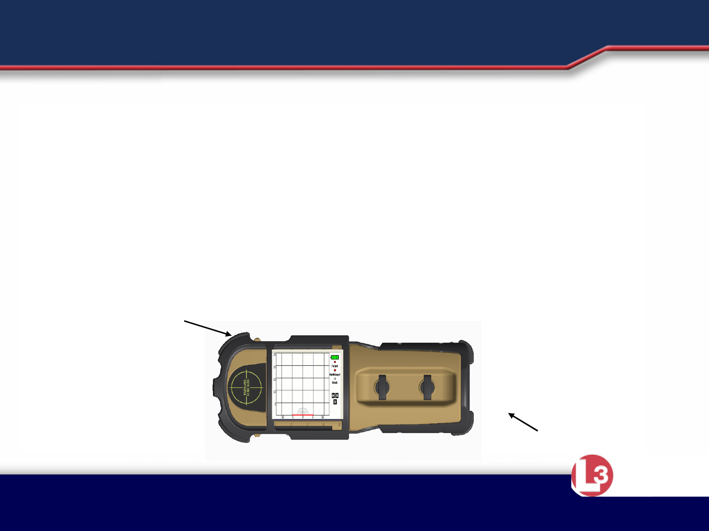
POWERING THE SYSTEM
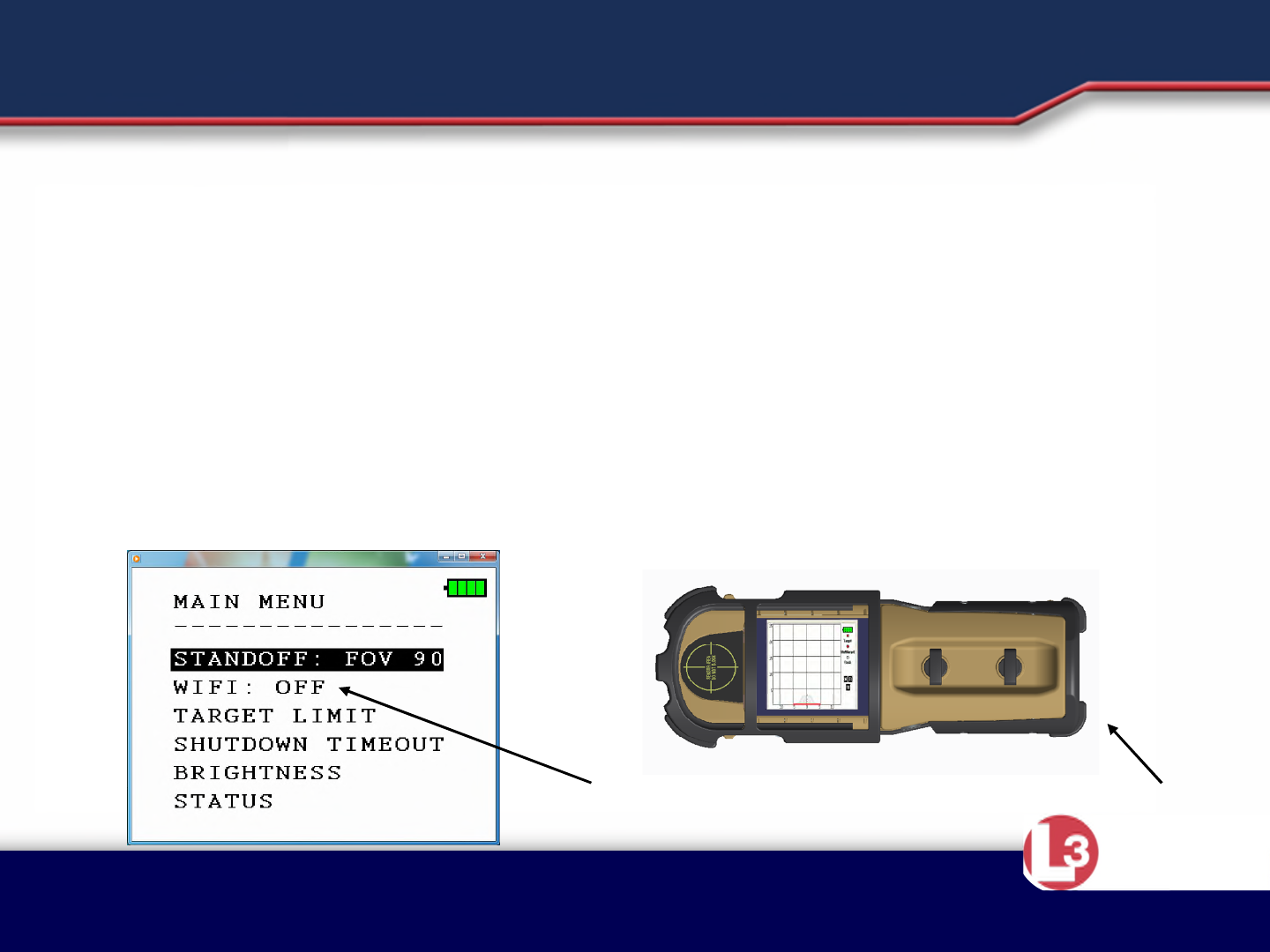
•The WiFi module is in the OFF setting when the sensor is initially powered
on.
•To enable WiFi, select WiFi from the main menu and it will toggle to the
on state.
–Note: Once enabled, WiFi remains on until power on the sensor is cycled off and then on
again. This implementation prevents accidental turning off WiFi from the remote device
and losing communication with the sensor.
•Remove the batteries when use of the system is completed to
prevent draining of the batteries.
WiFi Module
RANGE-R2D LINK
WiFi Enable
Approved for Public Release 20 October
2015 by U.S. Army Project Manager I2WD
CyTerra
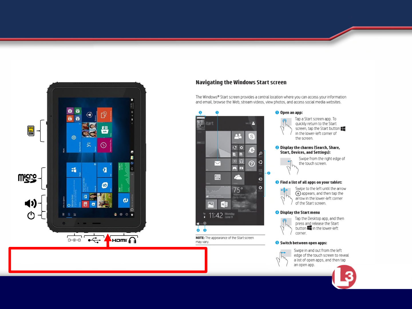
POWERING THE SYSTEM
•Power on the remote device, allow Microsoft Windows 10 to start, and
navigate to the RANGE-R2D Link App on the Windows Desktop
WIFI ANTENNAS!
Keep hands away from this edge for best results.
Approved for Public Release 20 October
2015 by U.S. Army Project Manager I2WD
CyTerra
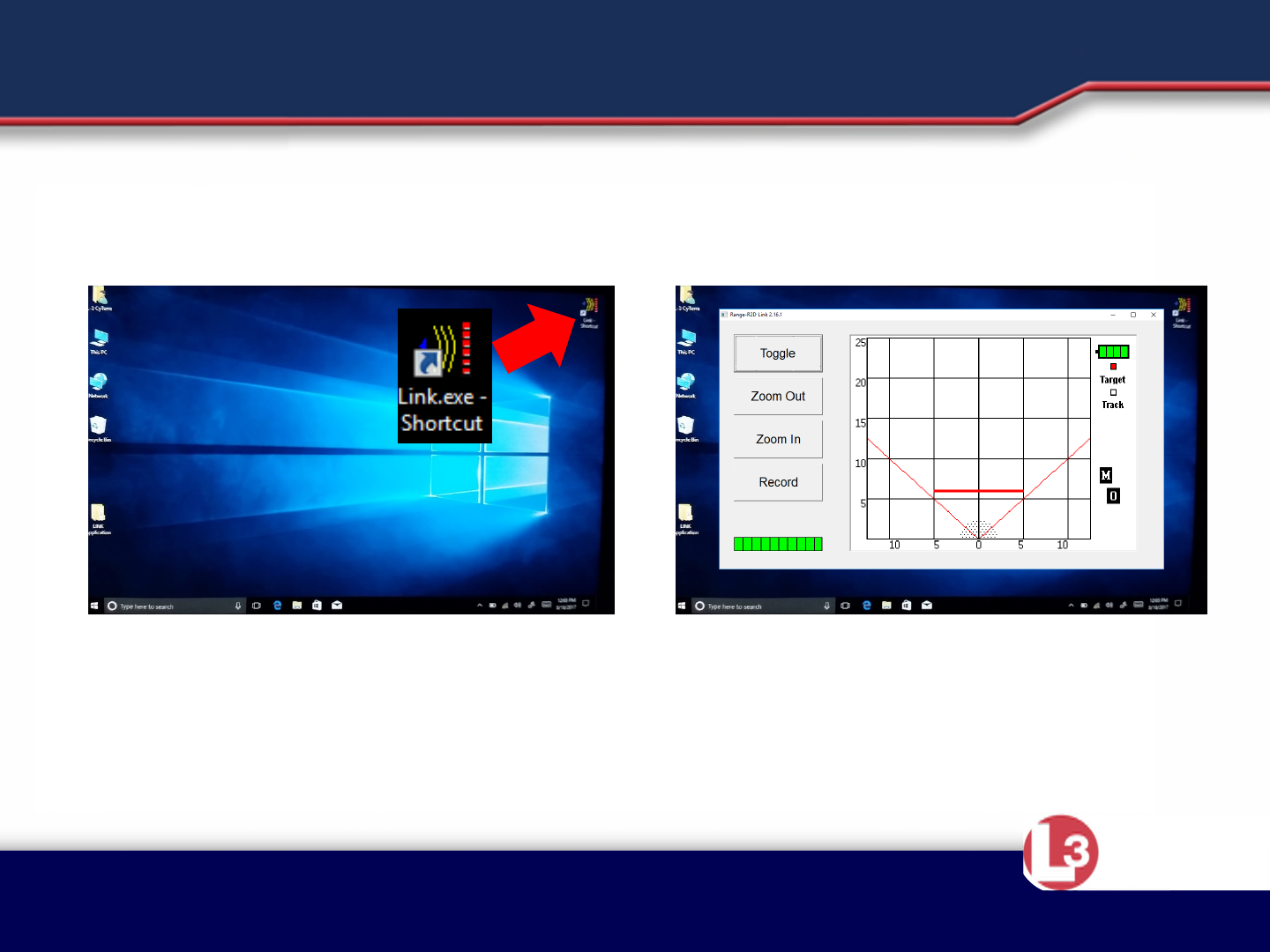
Using The Windows Application
•Double tap on the RANGE-R2D Link icon to
start the application.
•Application will connect to sensor
•Sensor will go into SCAN mode
Approved for Public Release 20 October
2015 by U.S. Army Project Manager I2WD
CyTerra
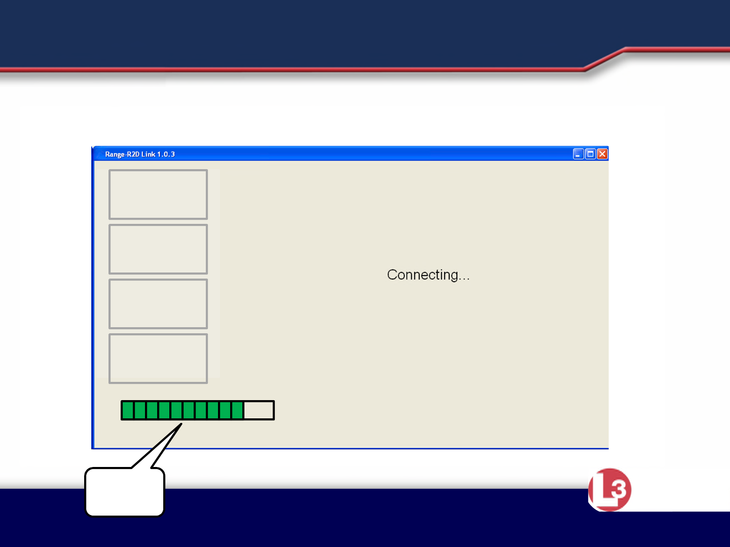
POWERING THE SYSTEM
•The app will open and the remote device will indicate it’s connecting to
the sensor.
Signal
Quality
TOGGLE
SELECT
NEXT
RECORD
Note: Do not cover the remote display
antennae
Approved for Public Release 20 October
2015 by U.S. Army Project Manager I2WD
CyTerra
POWERING THE SYSTEM
•When the remote device has completed connection to the sensor the
Main Menu display shown on the sensor display will show on the remote
device.
Press the Toggle button
To switch between the
Main Menu and Scanning
Press the Select button
To make a Menu selection
Press the Next button
To navigate the Menu
Selections
TOGGLE
SELECT
NEXT
RECORD
Press the Record button
To record the display to
The media card.
Approved for Public Release 20 October
2015 by U.S. Army Project Manager I2WD
CyTerra
POWERING THE SYSTEM
•When in scan mode, the display on the sensor is duplicated on the
remote device and the RANGE-R2D LINK operates as if the user
were holding it. Follow RANGE-R2D Operating Instructions for use.
TOGGLE
SELECT
NEXT
RECORD

Approved for Public Release 20 October
2015 by U.S. Army Project Manager I2WD
CyTerra
TURNING THE SYSTEM OFF
•Close the RANGE-R2D LINK application by tapping on the “X” in the
red box in the upper right hand corner of the display.
•Power the remote device off using the standard Windows 8.1
method.
•Squeeze and hold the two control buttons on the sensor until the
RANGE-R2D Link power off.
•Remove the batteries or disconnect external power from the
RANGE-R2D LINK.