L3 Technologies AFIRS228S Satellite Data Unit User Manual Iridium IO Rev 3 DRAFTx
L-3 Communications Satellite Data Unit Iridium IO Rev 3 DRAFTx
UserManual.wiki
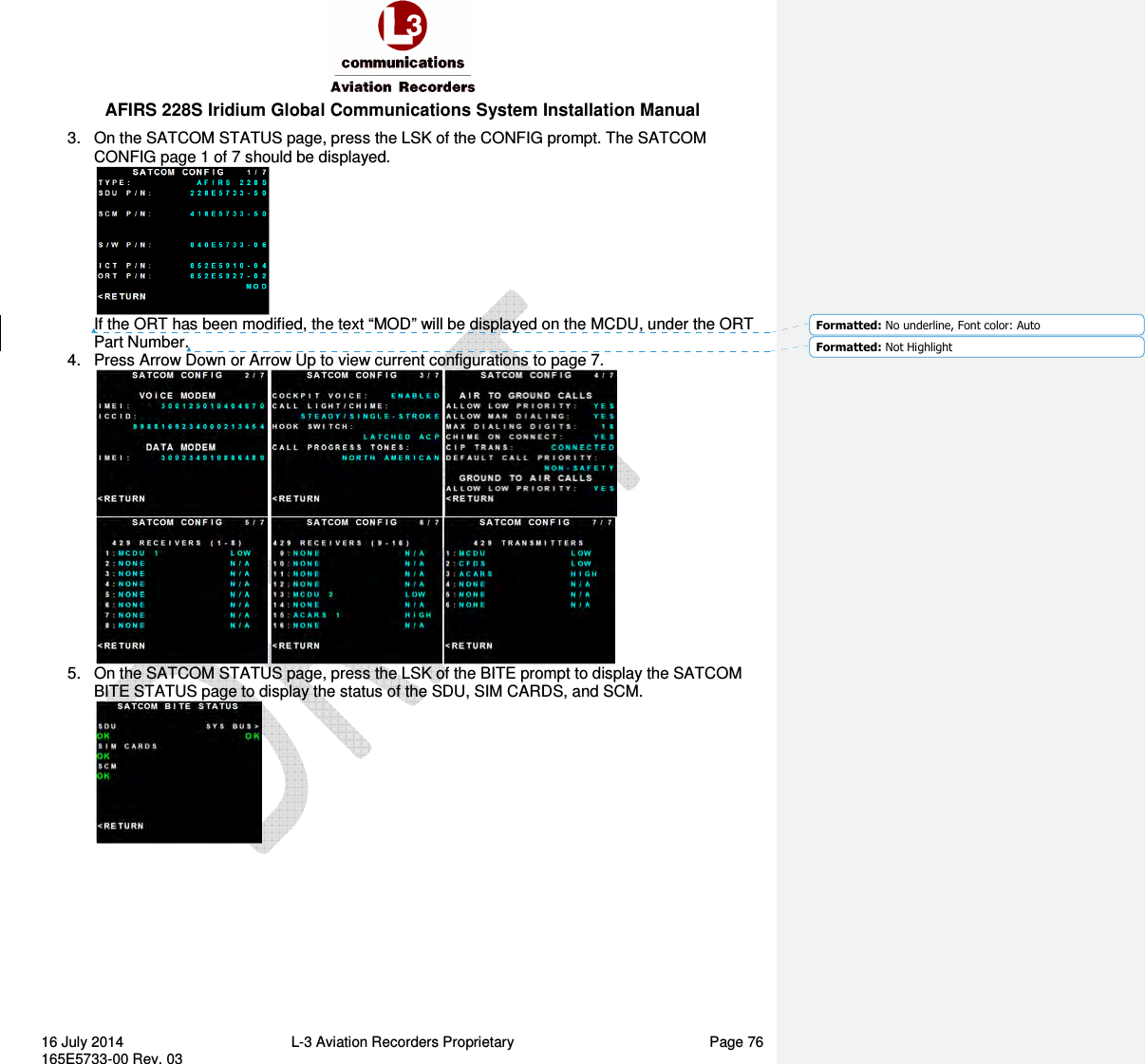
>
L3 Technologies
>
AFIRS228S User Manual
Manual
Navigation menu
Upload a User Manual
Namespaces
Wiki Guide
HTML
PDF
Info
Views
User Manual
Discussion / Help
Navigation
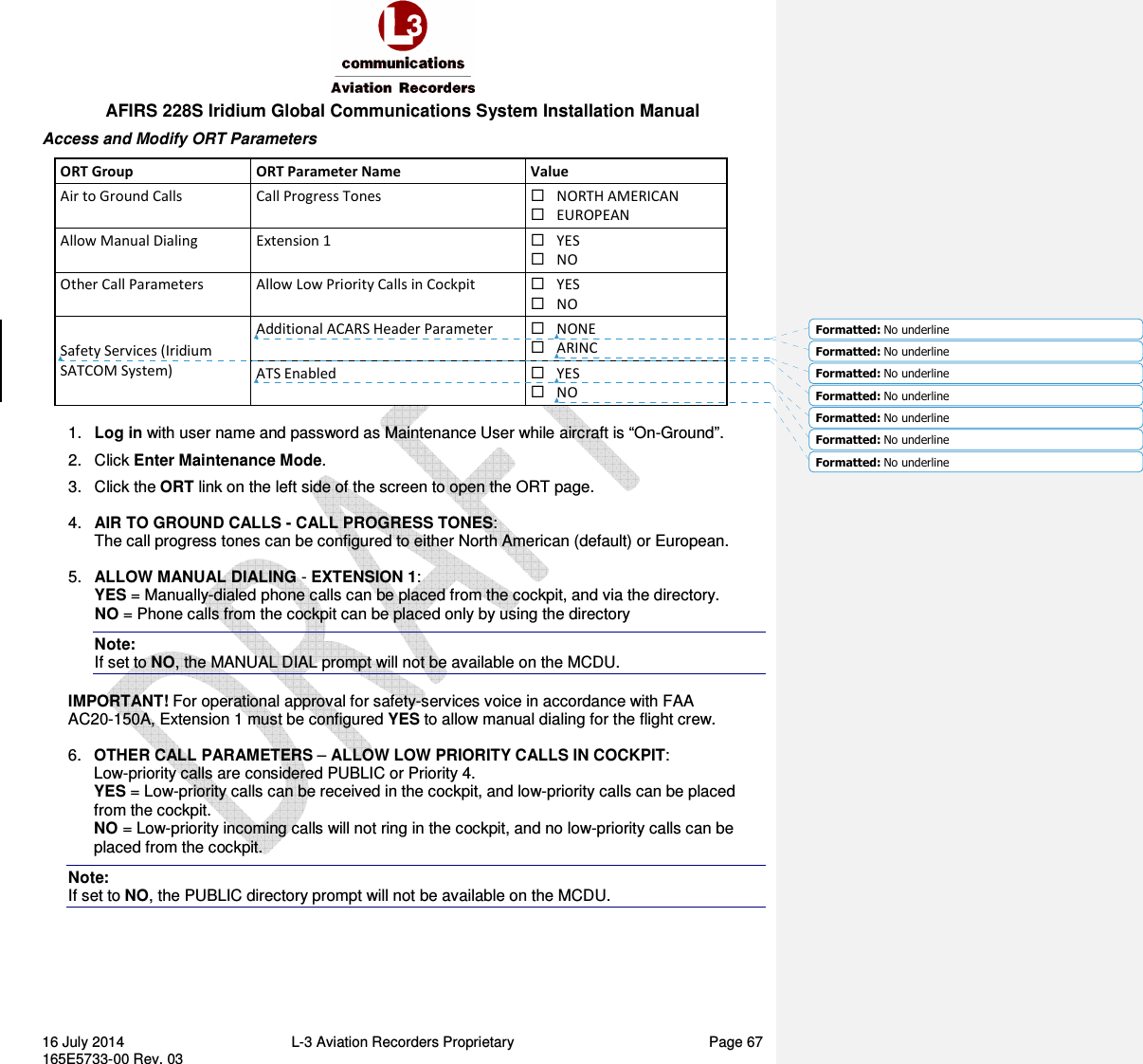
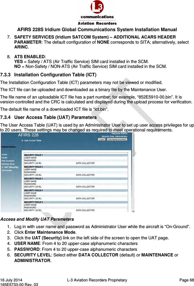
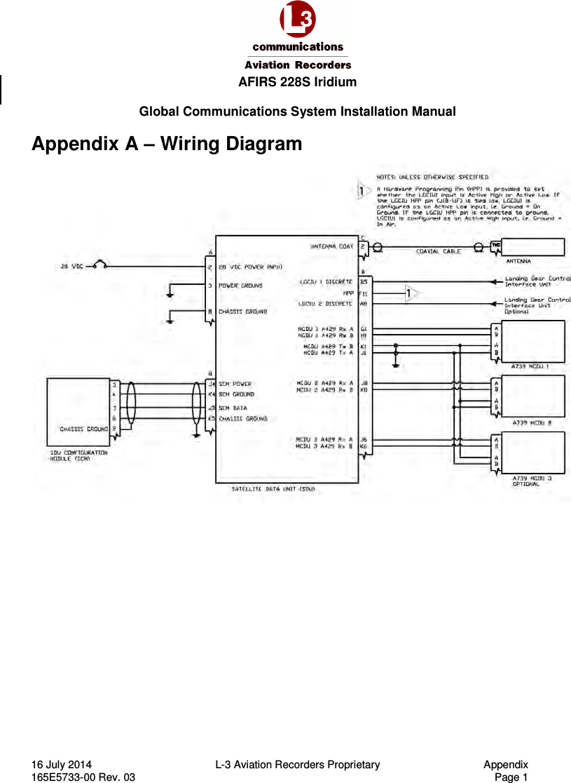
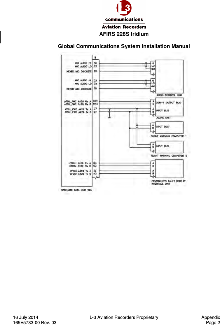
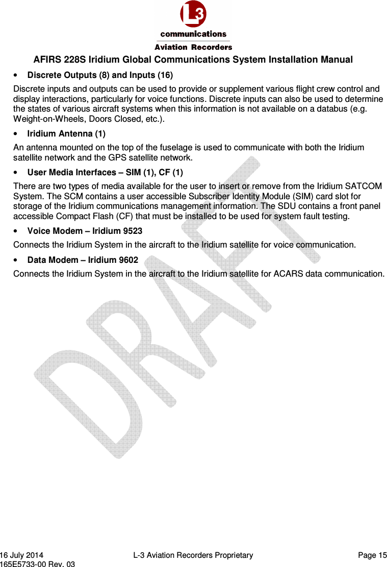
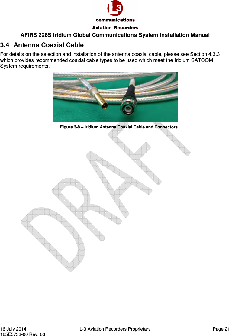
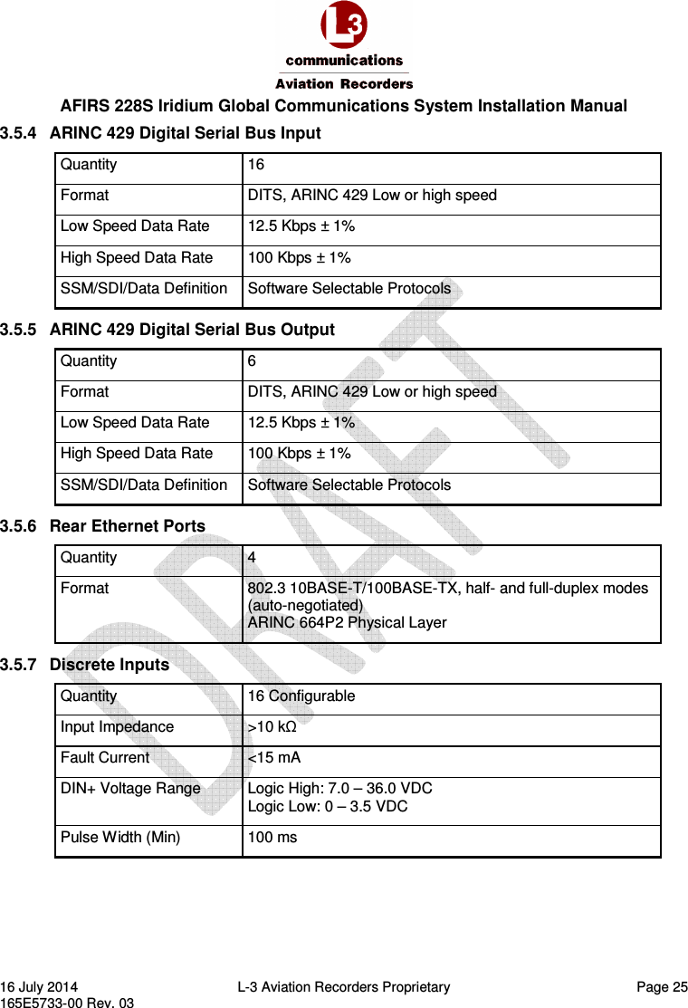
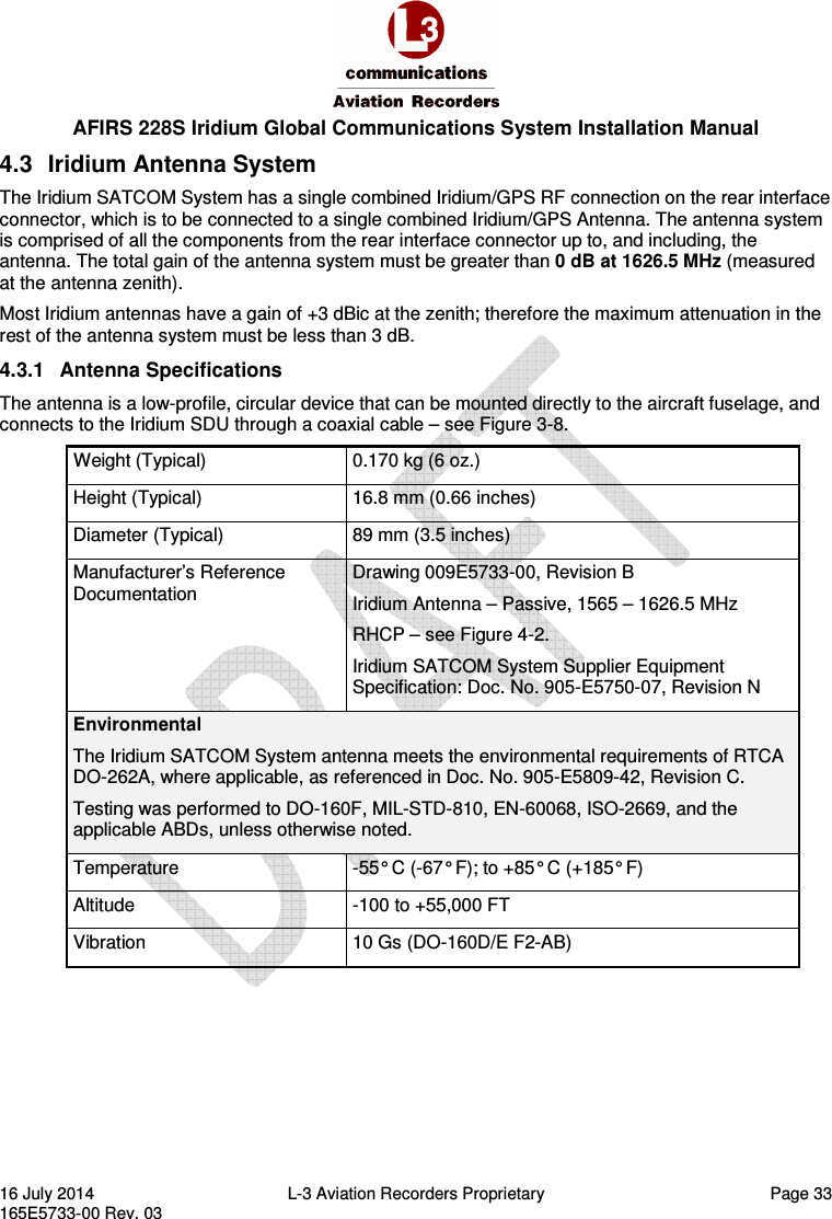
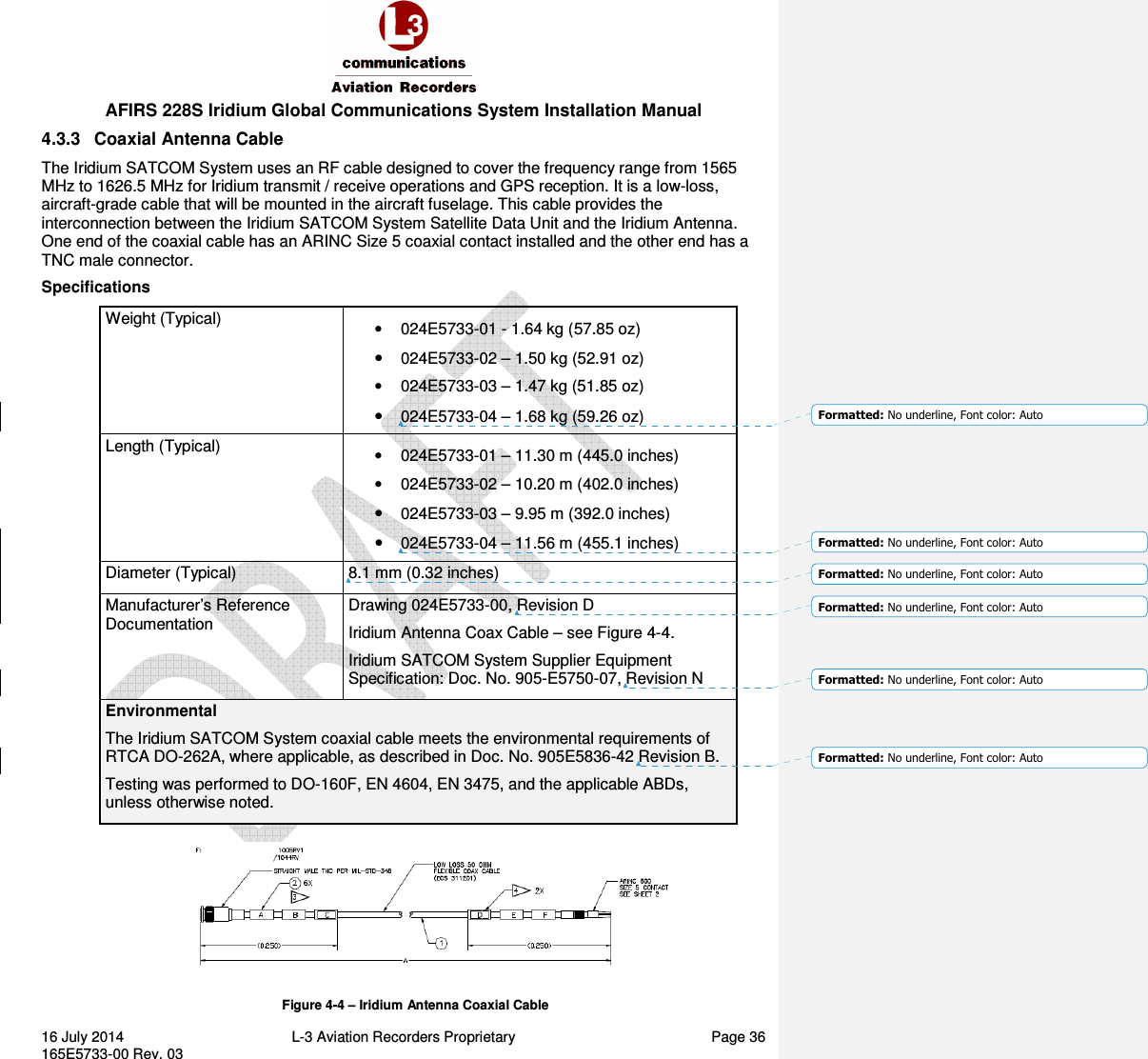
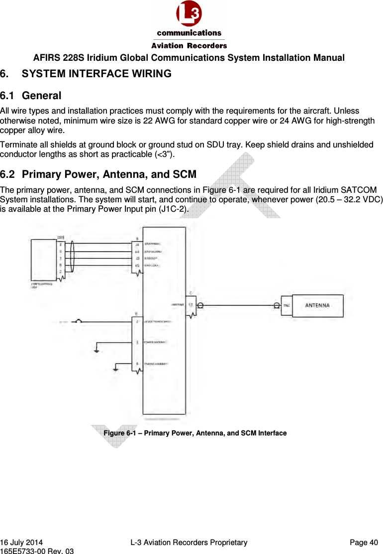
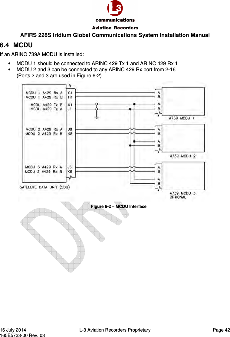
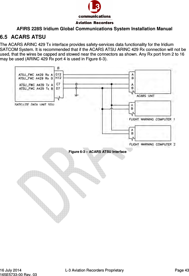
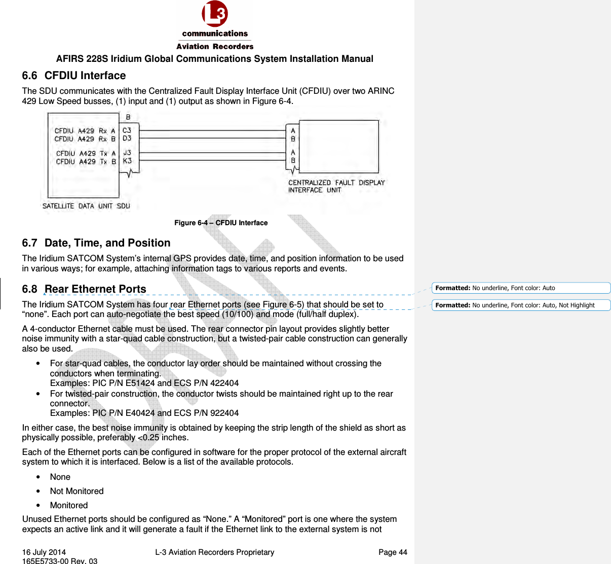
![AFIRS 228S Iridium Global Communications System Installation Manual 16 July 2014 L-3 Aviation Recorders Proprietary Page 4 165E5733-00 Rev. 03 7.2 Maintenance Mode ......................................................................................................... 56 7.2.1 Maintenance Mode Upgrades Page................................................................................................ 57 7.3 Configure the Iridium SATCOM System ........................................................................ 64 7.3.1 Address Book .................................................................................................................................... 64 7.3.2 Owner Requirements Table (ORT) Parameters .............................................................................. 66 7.3.3 Installation Configuration Table (ICT) ............................................................................................. 68 7.3.4 User Access Table (UAT) Parameters .............................................................................................. 68 7.4 Upgrade Iridium SATCOM System Software ................................................................ 69 7.4.1 Upgrade Materials ............................................................................................................................ 69 7.4.2 Upgrade the Iridium SATCOM System Software ............................................................................ 70 7.5 Exit Maintenance Mode .................................................................................................. 72 8. Maintenance and Checkout .................................................................................................... 74 8.1 Post-Installation Checkout ............................................................................................. 74 8.1.1 Before Power-On Tests .................................................................................................................... 74 8.1.2 Aircraft Systems Interface Tests ...................................................................................................... 74 8.1.3 Operational System Tests ................................................................................................................ 78 8.1.4 EMI Tests ........................................................................................................................................... 79 8.2 Instructions for Continued Airworthiness ....................................................................... 79 List of Figures FIGURE 2-1 –IRIDIUM SATCOM SYSTEM OPERATIONAL CONCEPT ............................................................................................. 12 FIGURE 2-2 –IRIDIUM SATCOM SYSTEM BLOCK DIAGRAM ......................................................................................................... 13 FIGURE 2-3 –IRIDIUM SATCOM SYSTEM EXTERNAL INTERFACES ............................................................................................... 14 FIGURE 3-1 –IRIDIUM SATCOM SYSTEM SATELLITE DATA UNIT (SDU) ....................................................................................... 16 FIGURE 3-2 – SDU OUTLINE DRAWING (DIMENSIONS IN [MILLIMETERS] AND INCHES) .......................................................... 17 FIGURE 3-3 –IRIDIUM SATCOM SYSTEM SDU CONFIGURATION MODULE (SCM) ..................................................................... 18 FIGURE 3-4 – SCM OBLIQUE VIEW ................................................................................................................................................ 19 FIGURE 3-5 – SCM CONNECTOR VIEW SHOWING LOCATION OF PIN 1 ...................................................................................... 19 FIGURE 3-6 – SCM OUTLINE DRAWING (DIMENSIONS IN [MILLIMETERS] AND INCHES) .......................................................... 20 FIGURE 3-7 –IRIDIUM SATCOM SYSTEM ANTENNA ..................................................................................................................... 20 FIGURE 3-8 – IRIDIUM ANTENNA COAXIAL CABLE AND CONNECTORS ...................................................................................... 21 FIGURE 3-9 – SDU CONNECTOR MAP ............................................................................................................................................ 24 FIGURE 4-1 – TYPICAL 2MCU MOUNTING TRAY FOR THE SDU ................................................................................................... 32 FIGURE 4-2 - IRIDIUM ANTENNA, OUTLINE AND DIMENSIONS .................................................................................................. 34 FIGURE 4-3 - IRIDIUM ANTENNA, GASKET .................................................................................................................................... 35 FIGURE 4-4 – IRIDIUM ANTENNA COAXIAL CABLE ....................................................................................................................... 36 FIGURE 6-1 – PRIMARY POWER, ANTENNA, AND SCM INTERFACE ............................................................................................ 40 FIGURE 6-2 – MCDU INTERFACE .................................................................................................................................................... 42 FIGURE 6-3 – ACARS ATSU INTERFACE .......................................................................................................................................... 43](https://usermanual.wiki/L3-Technologies/AFIRS228S/User-Guide-2772817-Page-8.png)
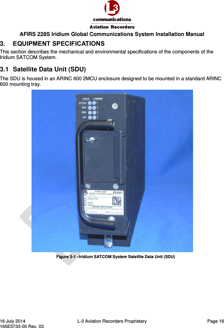
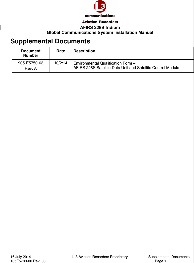
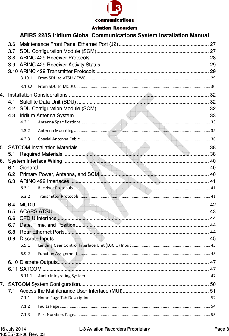
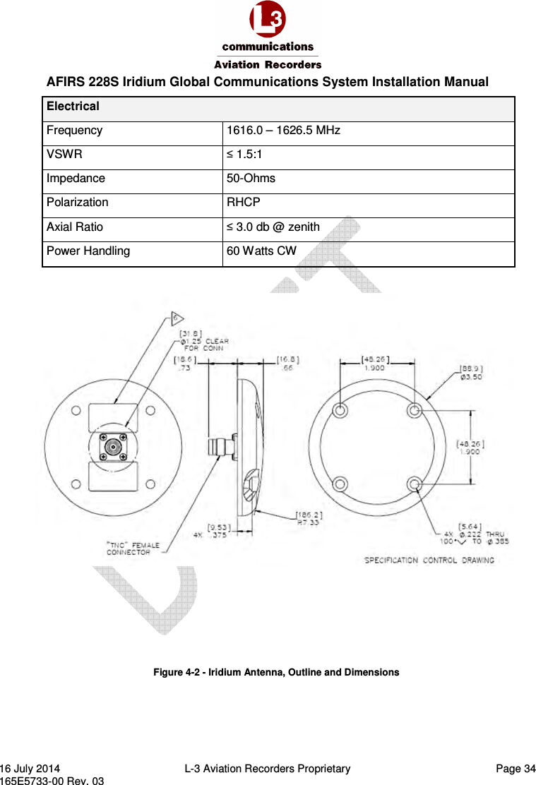
![AFIRS 228S Iridium Global Communications System Installation Manual 16 July 2014 L-3 Aviation Recorders Proprietary Page 17 165E5733-00 Rev. 03 3.1.1 Mechanical Specifications Dimensions 7.81” x 2.27” x 15.02” (198.3mm x 57.7mm x 381.5mm) Weight 7.7 lbs. (3.49 kg) Max Material/Finish Aluminum Alloy with Black Polyurethane Finish Mounting ARINC 600 2MCU Mounting Tray Rear Mating Connector Size 2 ARINC 600 Receptacle Radiall P/N: NSXN2P201S0004 Maintenance Connector RJ45 (8P8C) Modular Connector Jack Flash Card CompactFlash® (Type I or Type II) Figure 3-2 – SDU Outline Drawing (dimensions in [millimeters] and inches)](https://usermanual.wiki/L3-Technologies/AFIRS228S/User-Guide-2772817-Page-21.png)
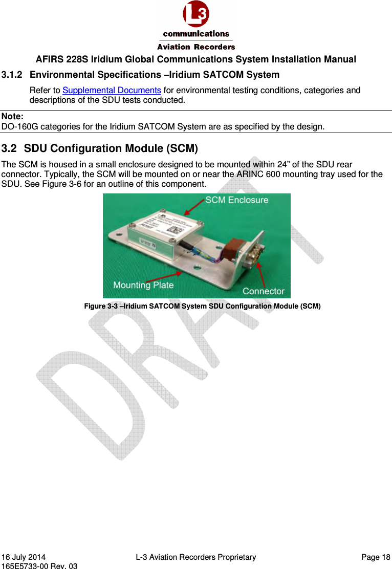
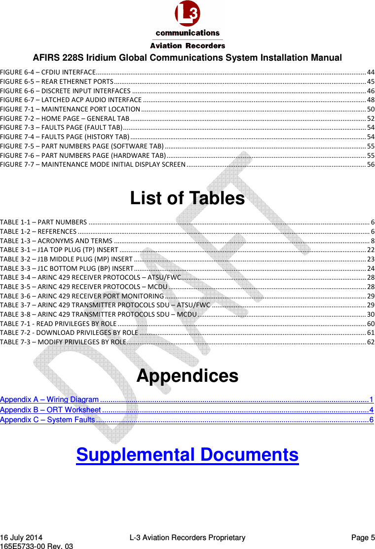
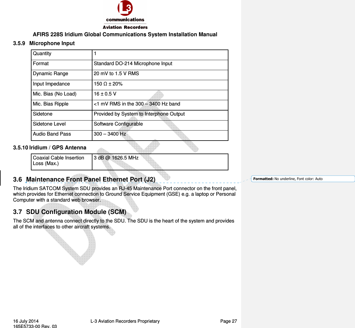
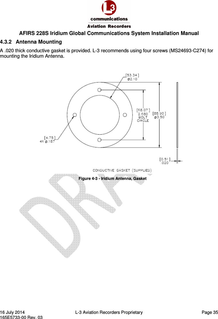
![AFIRS 228S Iridium Global Communications System Installation Manual 16 July 2014 L-3 Aviation Recorders Proprietary Page 20 165E5733-00 Rev. 03 Figure 3-6 – SCM Outline Drawing (dimensions in [millimeters] and inches) 3.2.2 Environmental Specifications Refer to Supplemental Documents for environmental testing conditions, categories, and descriptions of the SCM tests conducted. 3.3 Iridium SATCOM System Satellite Antenna The antenna is a Commercial Off the Shelf (COTS) unit that is mounted on the top of the aircraft’s fuselage. It provides satellite connectivity for both the GPS and Iridium satellite systems. Figure 3-7 –Iridium SATCOM System Antenna](https://usermanual.wiki/L3-Technologies/AFIRS228S/User-Guide-2772817-Page-24.png)


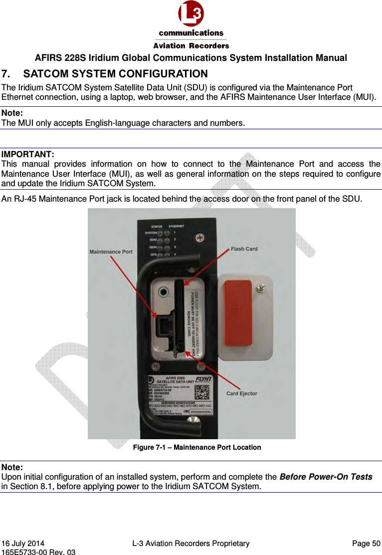
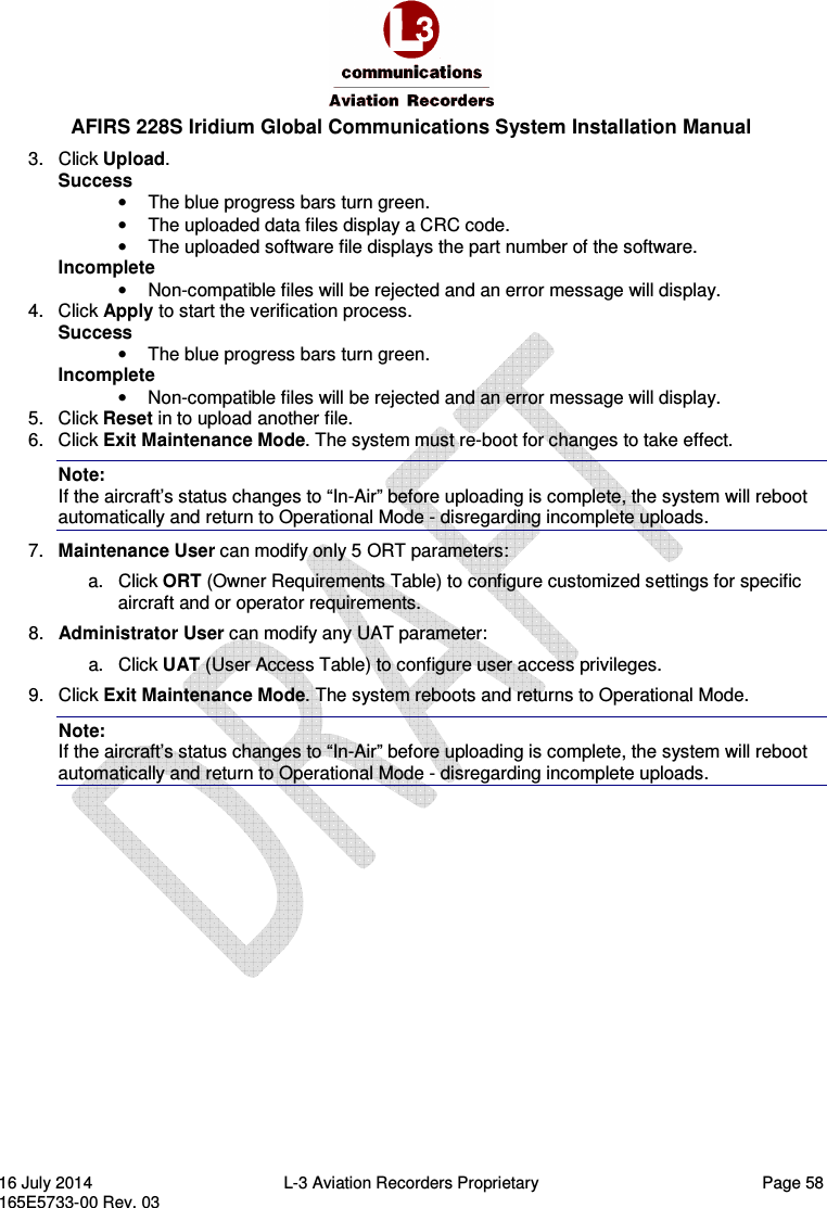
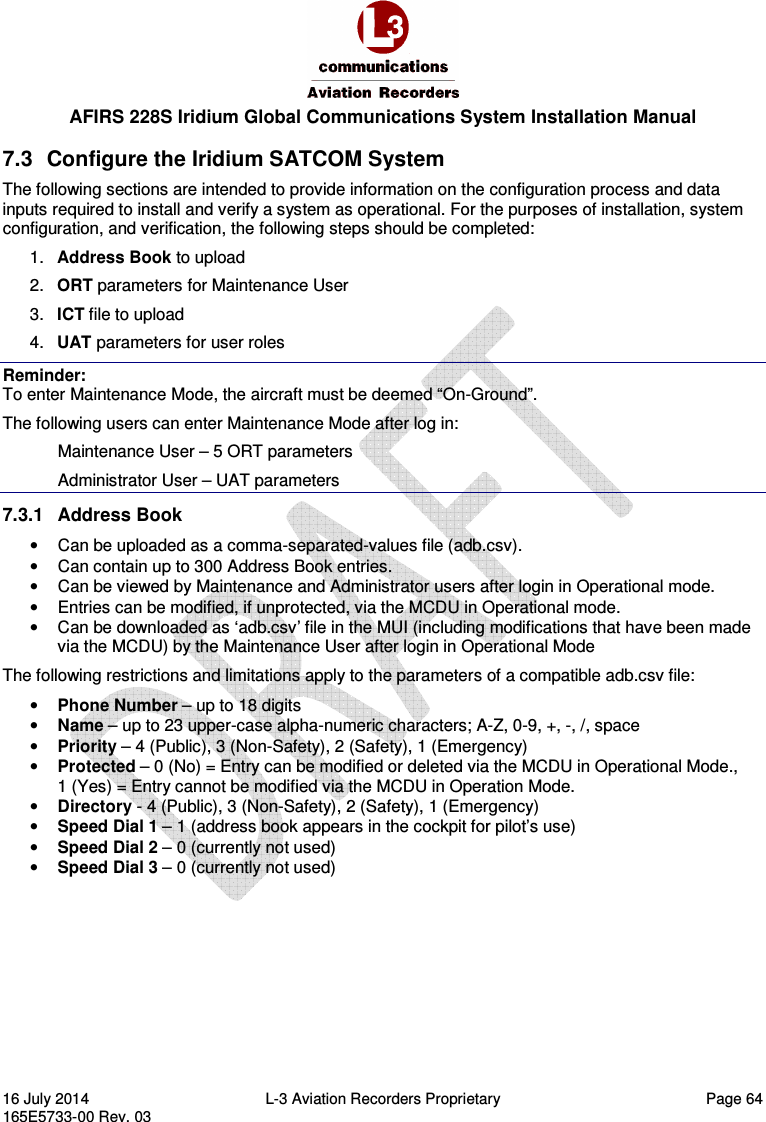
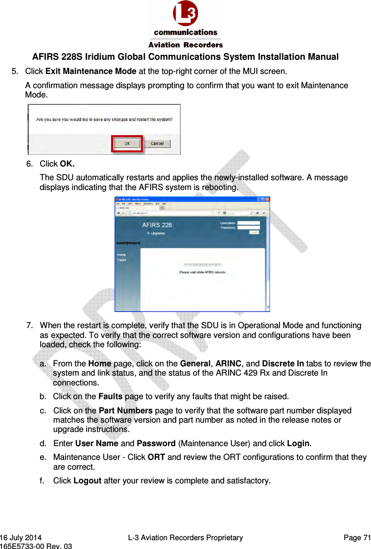
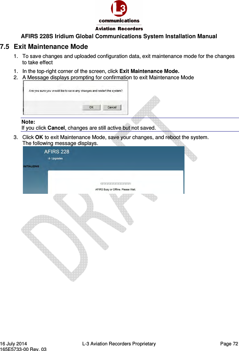
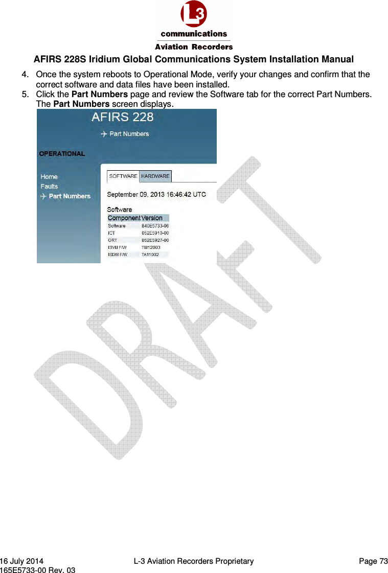
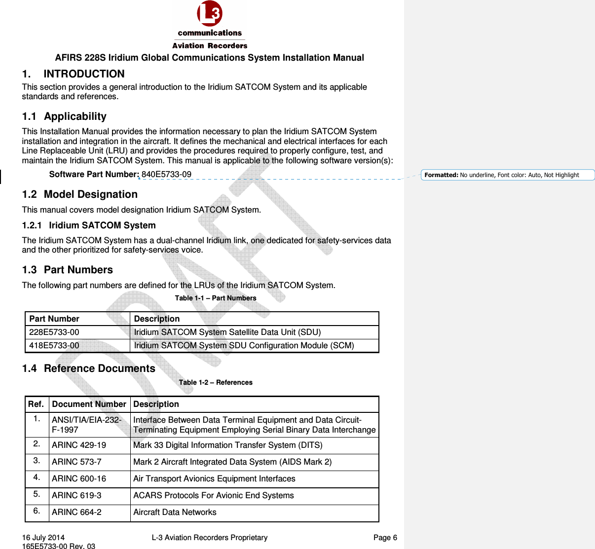
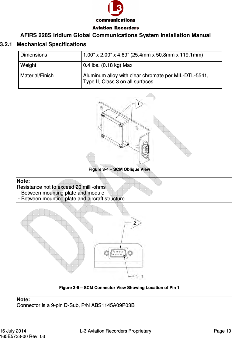
![AFIRS 228S Iridium Global Communications System Installation Manual 16 July 2014 L-3 Aviation Recorders Proprietary Page 56 165E5733-00 Rev. 03 7.2 Maintenance Mode To enter Maintenance Mode, the aircraft must be deemed “On-Ground.” If the aircraft is deemed “In-Air”, the [Enter Maintenance Mode] button will be, or will become, unavailable. If the aircraft status changes to “In-Air” while in Maintenance Mode, the system will reboot automatically and return to Operational Mode. The following users can enter Maintenance Mode after log in: Maintenance User (View Upgrades page, modify 5 parameters on the ORT page) Administrator User (View Upgrades page, modify parameters on the UAT page) Role-based MUI permissions are provided in Table 7-1 through Table 7-3 at the end of this section. Enter Maintenance Mode 1. Once connected to the Iridium SATCOM System MUI, on the Home page, enter your user name and password and click Login. 2. If the aircraft is deemed “On-Ground”, the [Enter Maintenance Mode] button is available at the top right corner of the screen. 3. Click Enter Maintenance Mode. The following message displays, prompting for confirmation to enter Maintenance Mode. 4. Click OK. The Home screen displays. The SYSTEM status indicates Yellow (blank). Note: Entering Maintenance Mode disables all MCDU functions. Figure 7-7 – Maintenance Mode Initial Display Screen](https://usermanual.wiki/L3-Technologies/AFIRS228S/User-Guide-2772817-Page-60.png)