L3 Technologies AFIRS228S Satellite Data Unit User Manual Iridium IO Rev 3 DRAFTx
L-3 Communications Satellite Data Unit Iridium IO Rev 3 DRAFTx
Manual

16 July 2014 L-3 Aviation Recorders Proprietary Page i
165E5733-00 Rev. 03
AFIRS 228S Iridium
Global Communications System
Installation Manual
Part Numbers
SDU: 228E5733-00
SCM: 418E5733-00
Publication: 165E5733-00 Rev. 03

AFIRS 228S Iridium Global Communications System Installation Manual
16 July 2014 L-3 Aviation Recorders Proprietary Page ii
165E5733-00 Rev. 03
EXPORT CONTROL STATEMENT IRIDIUM SATCOM
TECHNOLOGY / DATA:
“This Iridium SATCOM System Technical Data is being exported from
the United States in accordance with the Export Administration
Regulations (ECCN #7E994), No License Required (NLR). Diversion
contrary to U.S. law is prohibited. In accordance with U.S. Law (Title
15CFR Part 746 and Supplement No. 1 to Part 774; and Title 31CFR)
resale/re-export or transfer to certain designated countries is
prohibited without the prior written consent of the U.S. Department of
Commerce.”
HTSUS/Schedule B: 85439.09.000
This manual contains date-sensitive information. To verify the latest
revision level of this manual, visit our document down-load site at
http://www.L3ar.net.
©Copyright 2014 by L-3 Communications.
All rights reserved. No part of this manual may be reproduced or
utilized in any form or by any means, electronic or mechanical,
including photocopying, recording, or by information storage and
retrieval system, without permission in writing.
Inquiries should be addressed to:
L-3 Communications,
Aviation Recorders Publications
Vendor Code: 06141 P. O. Box 3041
Sarasota, Florida 34230
Phone: (941) 371–0811;
FAX: (941) 377–5591

AFIRS 228S Iridium Global Communications System Installation Manual
16 July 2014 L-3 Aviation Recorders Proprietary Page iii
165E5733-00 Rev. 03
FCC Certification
This device complies with Part 15 of the FCC rules. Operation is subject to the following
two conditions: (1) This device may not cause harmful interference, and (2) this device
must accept any interference received, including interference that may cause undesired
operation. Changes or modifications not expressly approved by the party responsible for
compliance could void the user’s authority to operate the equipment.
NOTE: This equipment has been tested and found to comply with the limits for a Class A
digital device, pursuant to part 15 of the FCC Rules. These limits are designed to pro-vide
reasonable protection against harmful interference when the equipment is operated in a
commercial environment. This equipment generates, uses, and can radiate radio frequency
energy and, if not installed and used in accordance with the instruction manual, may cause
harmful interference to radio communications. Operation of this equipment in a residential
area is likely to cause harmful interference in which case the user will be required to correct
the interference at his own expense.
AFIRS 228S Iridium Global Communications System Installation Manual
16 July 2014 L-3 Aviation Recorders Proprietary Page iv
165E5733-00 Rev. 03
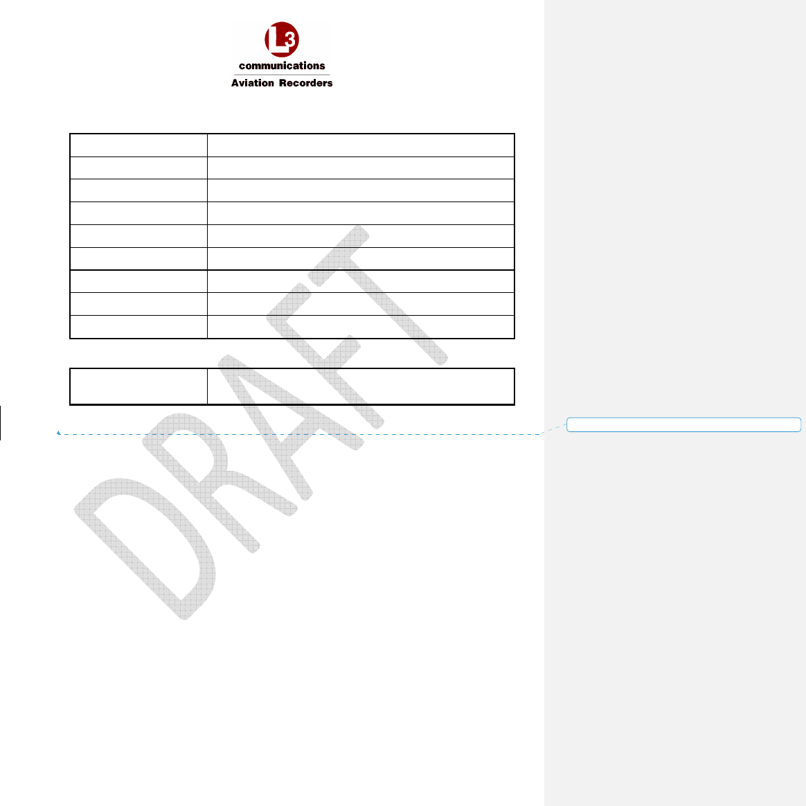
RECORD OF REVISIONS
Rev. Issue Date Description Pages By
00 01 November 2013 Initial issue. All CM
01 15 December 2013 Corrected SDU & SCM Top-
Level Part Numbers.
All CM/SC
02 21 January 2014 Corrected SDU & SCM Top-
Level Part Numbers.
All CP
03 16 July 2014 Software PN Change, removed
references to unused features,
removed non-configurable,
updated wiring diagrams, added
MCDU screenshots, added voice
and data modem models
1, 6, 7, 8,
9, 22, 23,
34, 38, 39,
70-73
CP

AFIRS 228S Iridium Global Communications System Installation Manual
16 July 2014 L-3 Aviation Recorders Proprietary Page 1
165E5733-00 Rev. 03
THIS PAGE INTENTIONALLY LEFT BLANK

AFIRS 228S Iridium Global Communications System Installation Manual
16 July 2014 L-3 Aviation Recorders Proprietary Page 2
165E5733-00 Rev. 03
Table of Contents
RECORD OF REVISIONS ............................................................................................................. iv
List of Figures ..................................................................................................................................4
List of Tables....................................................................................................................................5
Appendices ......................................................................................................................................5
Supplemental Documents ...............................................................................................................5
1. Introduction ................................................................................................................................6
1.1 Applicability ........................................................................................................................6
1.2 Model Designation .............................................................................................................6
1.2.1 Iridium SATCOM System .................................................................................................................... 6
1.3 Part Numbers ....................................................................................................................6
1.4 Reference Documents ......................................................................................................6
1.5 Definitions of Acronyms and Terms ..................................................................................8
2. Description and Operation ...................................................................................................... 12
2.1 System Overview ........................................................................................................... 12
2.2 System Architecture ....................................................................................................... 13
2.3 External System Interfaces ............................................................................................ 13
3. Equipment Specifications ....................................................................................................... 16
3.1 Satellite Data Unit (SDU) ............................................................................................... 16
3.1.1 Mechanical Specifications ............................................................................................................... 17
3.1.2 Environmental Specifications –Iridium SATCOM System .............................................................. 18
3.2 SDU Configuration Module (SCM) ................................................................................. 18
3.2.1 Mechanical Specifications ............................................................................................................... 19
3.2.2 Environmental Specifications .......................................................................................................... 20
3.3 Iridium SATCOM System Satellite Antenna .................................................................. 20
3.4 Antenna Coaxial Cable .................................................................................................. 21
3.5 Interface Specifications .................................................................................................. 22
3.5.1 SDU Rear Connector (J1) .................................................................................................................. 22
3.5.2 Power Input ...................................................................................................................................... 24
3.5.3 Chassis Ground ................................................................................................................................. 24
3.5.4 ARINC 429 Digital Serial Bus Input .................................................................................................. 25
3.5.5 ARINC 429 Digital Serial Bus Output ............................................................................................... 25
3.5.6 Rear Ethernet Ports .......................................................................................................................... 25
3.5.7 Discrete Inputs .................................................................................................................................. 25
3.5.8 Discrete Outputs............................................................................................................................... 26
3.5.9 Microphone Input ............................................................................................................................ 27
3.5.10 Iridium / GPS Antenna ..................................................................................................................... 27

AFIRS 228S Iridium Global Communications System Installation Manual
16 July 2014 L-3 Aviation Recorders Proprietary Page 3
165E5733-00 Rev. 03
3.6 Maintenance Front Panel Ethernet Port (J2) ................................................................. 27
3.7 SDU Configuration Module (SCM) ................................................................................. 27
3.8 ARINC 429 Receiver Protocols ...................................................................................... 28
3.9 ARINC 429 Receiver Activity Status .............................................................................. 29
3.10 ARINC 429 Transmitter Protocols.................................................................................. 29
3.10.1 From SDU to ATSU / FWC ................................................................................................................ 29
3.10.2 From SDU to MCDU .......................................................................................................................... 30
4. Installation Considerations ..................................................................................................... 32
4.1 Satellite Data Unit (SDU) ............................................................................................... 32
4.2 SDU Configuration Module (SCM) ................................................................................. 32
4.3 Iridium Antenna System ................................................................................................. 33
4.3.1 Antenna Specifications .................................................................................................................... 33
4.3.2 Antenna Mounting ........................................................................................................................... 35
4.3.3 Coaxial Antenna Cable ..................................................................................................................... 36
5. SATCOM Installation Materials .............................................................................................. 38
5.1 Required Materials ......................................................................................................... 38
6. System Interface Wiring ......................................................................................................... 40
6.1 General ........................................................................................................................... 40
6.2 Primary Power, Antenna, and SCM ............................................................................... 40
6.3 ARINC 429 Interfaces .................................................................................................... 41
6.3.1 Receiver Protocols ............................................................................................................................ 41
6.3.2 Transmitter Protocols ...................................................................................................................... 41
6.4 MCDU ............................................................................................................................. 42
6.5 ACARS ATSU ................................................................................................................ 43
6.6 CFDIU Interface ............................................................................................................. 44
6.7 Date, Time, and Position ................................................................................................ 44
6.8 Rear Ethernet Ports........................................................................................................ 44
6.9 Discrete Inputs ............................................................................................................... 45
6.9.1 Landing Gear Control Interface Unit (LGCIU) Input ....................................................................... 45
6.9.2 Function Assignment ........................................................................................................................ 45
6.10 Discrete Outputs ............................................................................................................. 47
6.11 SATCOM ........................................................................................................................ 47
6.11.1 Audio Integrating System ................................................................................................................ 47
7. SATCOM System Configuration ............................................................................................. 50
7.1 Access the Maintenance User Interface (MUI) .............................................................. 51
7.1.1 Home Page Tab Descriptions ........................................................................................................... 52
7.1.2 Faults Page ........................................................................................................................................ 54
7.1.3 Part Numbers Page........................................................................................................................... 55

AFIRS 228S Iridium Global Communications System Installation Manual
16 July 2014 L-3 Aviation Recorders Proprietary Page 4
165E5733-00 Rev. 03
7.2 Maintenance Mode ......................................................................................................... 56
7.2.1 Maintenance Mode Upgrades Page................................................................................................ 57
7.3 Configure the Iridium SATCOM System ........................................................................ 64
7.3.1 Address Book .................................................................................................................................... 64
7.3.2 Owner Requirements Table (ORT) Parameters .............................................................................. 66
7.3.3 Installation Configuration Table (ICT) ............................................................................................. 68
7.3.4 User Access Table (UAT) Parameters .............................................................................................. 68
7.4 Upgrade Iridium SATCOM System Software ................................................................ 69
7.4.1 Upgrade Materials ............................................................................................................................ 69
7.4.2 Upgrade the Iridium SATCOM System Software ............................................................................ 70
7.5 Exit Maintenance Mode .................................................................................................. 72
8. Maintenance and Checkout .................................................................................................... 74
8.1 Post-Installation Checkout ............................................................................................. 74
8.1.1 Before Power-On Tests .................................................................................................................... 74
8.1.2 Aircraft Systems Interface Tests ...................................................................................................... 74
8.1.3 Operational System Tests ................................................................................................................ 78
8.1.4 EMI Tests ........................................................................................................................................... 79
8.2 Instructions for Continued Airworthiness ....................................................................... 79
List of Figures
FIGURE 2-1 –IRIDIUM SATCOM SYSTEM OPERATIONAL CONCEPT ............................................................................................. 12
FIGURE 2-2 –IRIDIUM SATCOM SYSTEM BLOCK DIAGRAM ......................................................................................................... 13
FIGURE 2-3 –IRIDIUM SATCOM SYSTEM EXTERNAL INTERFACES ............................................................................................... 14
FIGURE 3-1 –IRIDIUM SATCOM SYSTEM SATELLITE DATA UNIT (SDU) ....................................................................................... 16
FIGURE 3-2 – SDU OUTLINE DRAWING (DIMENSIONS IN [MILLIMETERS] AND INCHES) .......................................................... 17
FIGURE 3-3 –IRIDIUM SATCOM SYSTEM SDU CONFIGURATION MODULE (SCM) ..................................................................... 18
FIGURE 3-4 – SCM OBLIQUE VIEW ................................................................................................................................................ 19
FIGURE 3-5 – SCM CONNECTOR VIEW SHOWING LOCATION OF PIN 1 ...................................................................................... 19
FIGURE 3-6 – SCM OUTLINE DRAWING (DIMENSIONS IN [MILLIMETERS] AND INCHES) .......................................................... 20
FIGURE 3-7 –IRIDIUM SATCOM SYSTEM ANTENNA ..................................................................................................................... 20
FIGURE 3-8 – IRIDIUM ANTENNA COAXIAL CABLE AND CONNECTORS ...................................................................................... 21
FIGURE 3-9 – SDU CONNECTOR MAP ............................................................................................................................................ 24
FIGURE 4-1 – TYPICAL 2MCU MOUNTING TRAY FOR THE SDU ................................................................................................... 32
FIGURE 4-2 - IRIDIUM ANTENNA, OUTLINE AND DIMENSIONS .................................................................................................. 34
FIGURE 4-3 - IRIDIUM ANTENNA, GASKET .................................................................................................................................... 35
FIGURE 4-4 – IRIDIUM ANTENNA COAXIAL CABLE ....................................................................................................................... 36
FIGURE 6-1 – PRIMARY POWER, ANTENNA, AND SCM INTERFACE ............................................................................................ 40
FIGURE 6-2 – MCDU INTERFACE .................................................................................................................................................... 42
FIGURE 6-3 – ACARS ATSU INTERFACE .......................................................................................................................................... 43

AFIRS 228S Iridium Global Communications System Installation Manual
16 July 2014 L-3 Aviation Recorders Proprietary Page 5
165E5733-00 Rev. 03
FIGURE 6-4 – CFDIU INTERFACE..................................................................................................................................................... 44
FIGURE 6-5 – REAR ETHERNET PORTS ........................................................................................................................................... 45
FIGURE 6-6 – DISCRETE INPUT INTERFACES ................................................................................................................................. 46
FIGURE 6-7 – LATCHED ACP AUDIO INTERFACE ........................................................................................................................... 48
FIGURE 7-1 – MAINTENANCE PORT LOCATION ............................................................................................................................ 50
FIGURE 7-2 – HOME PAGE – GENERAL TAB .................................................................................................................................. 52
FIGURE 7-3 – FAULTS PAGE (FAULT TAB) ...................................................................................................................................... 54
FIGURE 7-4 – FAULTS PAGE (HISTORY TAB) .................................................................................................................................. 54
FIGURE 7-5 – PART NUMBERS PAGE (SOFTWARE TAB) ............................................................................................................... 55
FIGURE 7-6 – PART NUMBERS PAGE (HARDWARE TAB) .............................................................................................................. 55
FIGURE 7-7 – MAINTENANCE MODE INITIAL DISPLAY SCREEN ................................................................................................... 56
List of Tables
TABLE 1-1 – PART NUMBERS ........................................................................................................................................................... 6
TABLE 1-2 – REFERENCES ................................................................................................................................................................. 6
TABLE 1-3 – ACRONYMS AND TERMS ............................................................................................................................................. 8
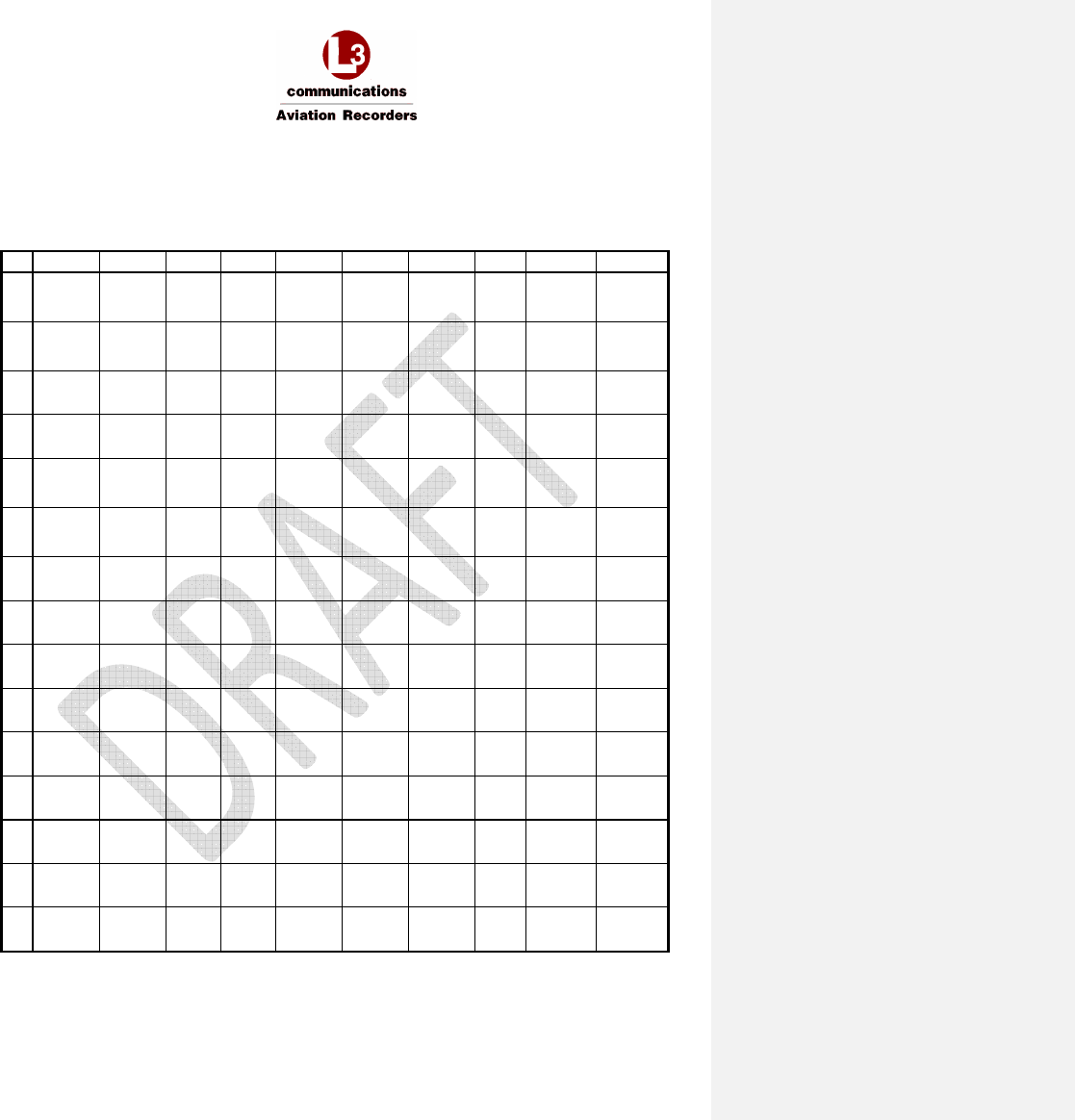
TABLE 3-1 – J1A TOP PLUG (TP) INSERT ........................................................................................................................................ 22
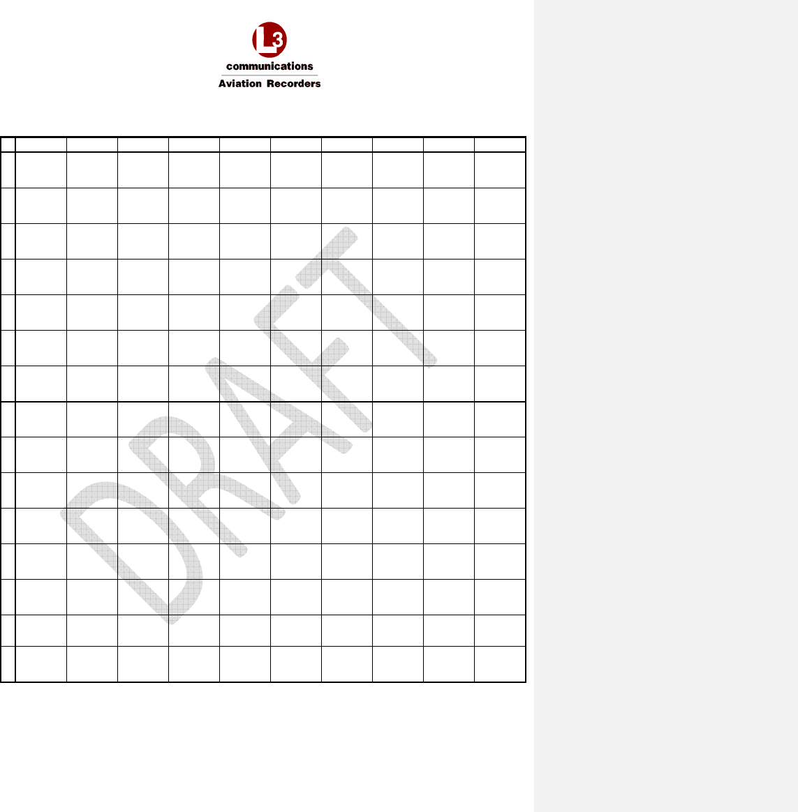
TABLE 3-2 – J1B MIDDLE PLUG (MP) INSERT ................................................................................................................................ 23
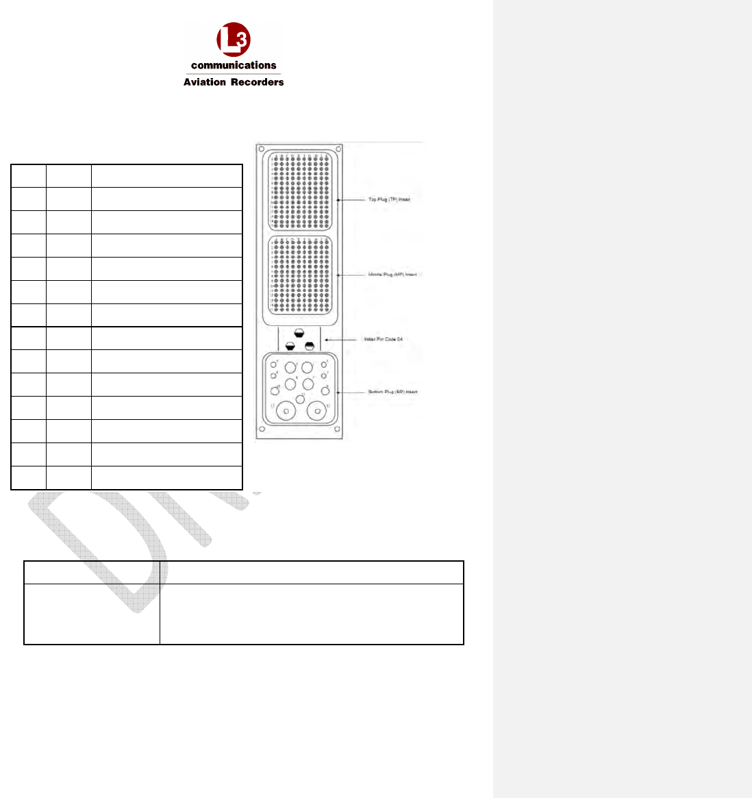
TABLE 3-3 – J1C BOTTOM PLUG (BP) INSERT ................................................................................................................................ 24
TABLE 3-4 – ARINC 429 RECEIVER PROTOCOLS – ATSU/FWC...................................................................................................... 28
TABLE 3-5 – ARINC 429 RECEIVER PROTOCOLS – MCDU ............................................................................................................. 28
TABLE 3-6 – ARINC 429 RECEIVER PORT MONITORING ............................................................................................................... 29
TABLE 3-7 – ARINC 429 TRANSMITTER PROTOCOLS SDU – ATSU/FWC ..................................................................................... 29
TABLE 3-8 – ARINC 429 TRANSMITTER PROTOCOLS SDU – MCDU ............................................................................................. 30
TABLE 7-1 - READ PRIVILEGES BY ROLE ......................................................................................................................................... 60
TABLE 7-2 - DOWNLOAD PRIVILEGES BY ROLE ............................................................................................................................. 61
TABLE 7-3 – MODIFY PRIVILEGES BY ROLE .................................................................................................................................... 62
Appendices
Appendix A – Wiring Diagram ................................................................................................................................. 1
Appendix B – ORT Worksheet ................................................................................................................................ 4
Appendix C – System Faults ................................................................................................................................... 6
Supplemental Documents
AFIRS 228S Iridium Global Communications System Installation Manual
16 July 2014 L-3 Aviation Recorders Proprietary Page 6
165E5733-00 Rev. 03
1. INTRODUCTION
This section provides a general introduction to the Iridium SATCOM System and its applicable
standards and references.
1.1 Applicability
This Installation Manual provides the information necessary to plan the Iridium SATCOM System
installation and integration in the aircraft. It defines the mechanical and electrical interfaces for each
Line Replaceable Unit (LRU) and provides the procedures required to properly configure, test, and
maintain the Iridium SATCOM System. This manual is applicable to the following software version(s):
Software Part Number: 840E5733-09
1.2 Model Designation
This manual covers model designation Iridium SATCOM System.
1.2.1 Iridium SATCOM System
The Iridium SATCOM System has a dual-channel Iridium link, one dedicated for safety-services data
and the other prioritized for safety-services voice.
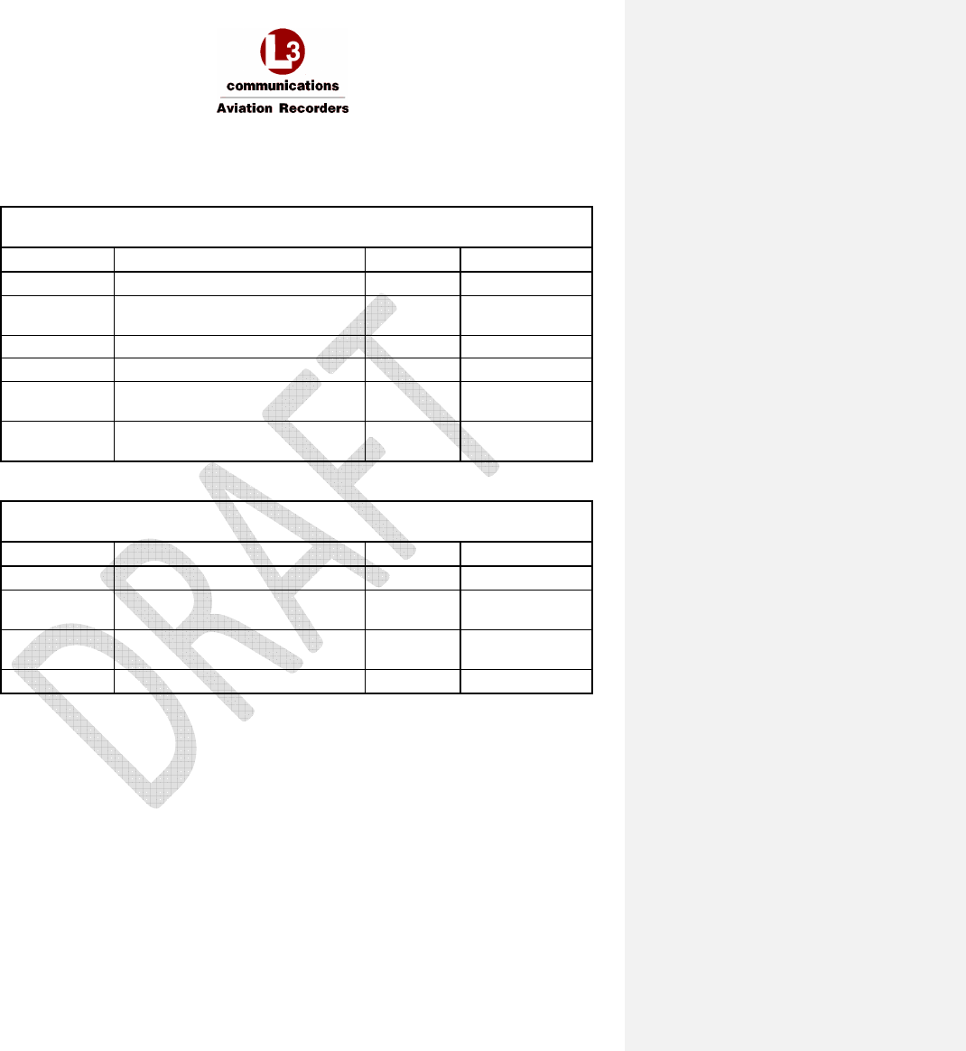
1.3 Part Numbers
The following part numbers are defined for the LRUs of the Iridium SATCOM System.
Table 1-1 – Part Numbers
Part Number Description
228E5733-00 Iridium SATCOM System Satellite Data Unit (SDU)
418E5733-00 Iridium SATCOM System SDU Configuration Module (SCM)
1.4 Reference Documents
Table 1-2 – References
Ref. Document Number
Description
1.
ANSI/TIA/EIA-232-
F-1997
Interface Between Data Terminal Equipment and Data Circuit-
Terminating Equipment Employing Serial Binary Data Interchange
2.
ARINC 429-19 Mark 33 Digital Information Transfer System (DITS)
3.
ARINC 573-7 Mark 2 Aircraft Integrated Data System (AIDS Mark 2)
4.
ARINC 600-16 Air Transport Avionics Equipment Interfaces
5.
ARINC 619-3 ACARS Protocols For Avionic End Systems
6.
ARINC 664-2 Aircraft Data Networks
Formatted: No underline, Font color: Auto, Not Highlight
AFIRS 228S Iridium Global Communications System Installation Manual
16 July 2014 L-3 Aviation Recorders Proprietary Page 7
165E5733-00 Rev. 03
Ref. Document Number
Description
7.
ARINC 702-6 Flight Management Computer System
8.
ARINC 702A-3 Advanced Flight Management Computer System
9.
ARINC 717-14 Flight Data Acquisition and Recording System
10.
ARINC 718-4 Mark 3 Air Traffic Control Transponder (ATCRBS/MODE S)
11.
ARINC 718A-2 Mark 4 Air Traffic Control Transponder (ATCRBS/MODE S)
12.
ARINC 739A-1 Multi-Purpose Control And Display Unit
13.
ARINC 741-13 Aviation Satellite Communication System
14.
ARINC 758-2 Communications Management Unit (CMU) Mark 2
15.
ARINC 761-4 Second Generation Aviation Satellite Communication System,
Aircraft Installation Provisions
16.
FAA TSO C-159a Technical Standard Order, Avionics Supporting Next Generation
Satellite Systems (NGSS)
17.
GAMA Publication
No. 11, Ver. 5.1
ARINC 429, General Aviation Subset
18.
IEEE 802.3-2008 IEEE Standard for Information Technology-Specific Requirements
- Part 3: Carrier Sense Multiple Access with Collision Detection
(CMSA/CD) Access Method and Physical Layer Specifications
19.
RTCA/DO-160G Environmental Conditions and Test Procedures for Airborne
Equipment
20.
RTCA/DO-214 Audio Systems Characteristics and Minimum Operational
Performance Standards for Aircraft Audio Systems and
Equipment
21.
RTCA/DO-262A Minimum Operational Performance Standards for Avionics
Supporting Next Generation Satellite Systems (NGSS)
22.
TIA/EIA-422-B Electrical Characteristics of Balanced Voltage Digital Interface
Circuits

AFIRS 228S Iridium Global Communications System Installation Manual
16 July 2014 L-3 Aviation Recorders Proprietary Page 8
165E5733-00 Rev. 03
1.5 Definitions of Acronyms and Terms
Table 1-3 – Acronyms and Terms
Acronym Definition
ACARS Aircraft Communications Addressing and Reporting System
ACP Audio Control Panel
ADB Address Book
AFIRS Automated Flight Information Reporting System
ANSI American National Standards Institute
APU Auxiliary Power Unit
ATE Automatic Test Equipment
ATS Air Traffic Service
ATSU Air Traffic Service Unit
ARINC Aeronautical Radio Incorporated
AWG American Wire Gauge
BCD Binary Coded Decimal
BITE Built-In Test Equipment
BOP Bit Oriented Protocol
BP Bottom Plug
BSP Board Support Package
CF Compact Flash
CNSSA Core Non-Safety Services Application
CTS Clear To Send
DITS Digital Information Transfer System
DTP Date Time Position
EFB Electronic Flight Bag
EIA Electronics Industry Association
ELA Embedded Logic Application
FAA Federal Aviation Administration
F/W Firmware

AFIRS 228S Iridium Global Communications System Installation Manual
16 July 2014 L-3 Aviation Recorders Proprietary Page 9
165E5733-00 Rev. 03
Acronym Definition
FWC Flight Warning Computer
GAMA General Aviation Manufacturers Association
GFI General Format Identifier
GPS Global Positioning System
GSE Ground Service Equipment
HBP Harvard Bi-Phase
HYB Hybrid
ICA Instructions for Continued Airworthiness
ICAO International Civil Aviation Organization
ICD Interface Control Document
ICE Iridium Certified Equipment
ICT Installation Configuration Table
IEEE Institute of Electrical and Electronics Engineers
IMEI International Mobile Equipment Identifier
ISO International Organization for Standardization
LGCIU Landing Gear Control Interface Unit
LED Light Emitting Diode
LRU Line Replaceable Unit
LSK Line Select Key
MCDU Multi-Purpose Control and Display Unit
MOPS Minimum Operational Performance Specifications
MP Middle Plug
MUI Maintenance User Interface
N/C Normally Closed
NGSS Next Generation Satellite Systems
N/O Normally Open
ORT Owner Requirements Table
PBX Public Branch Exchange

AFIRS 228S Iridium Global Communications System Installation Manual
16 July 2014 L-3 Aviation Recorders Proprietary Page 10
165E5733-00 Rev. 03
Acronym Definition
PC Personal Computer
P/N Part Number
PSTN Public Switched Telephone Network
PTT Push To Talk
RMS Root-Mean-Square
RTS Request To Send
RTCA Radio Technical Commission for Aeronautics
RX Receive
SAL System Address Label
SATCOM Satellite Communications
SCM SDU Configuration Module
SDI Source/Destination Identifier
SDU Satellite Data Unit
SIM Subscriber Identity Module
SSA Safety Service Application
SSM Signed Status Matrix
SW Software
TIA Telecommunications Industry Association
TNC Threaded Neill–Concelman
TP Top Plug
TX Transmit
TSO Technical Standard Order
UAT User Access Table
UTC Coordinated Universal Time
VAC Volts Alternating Current
VDC Volts Direct Current
WPS Words Per Second

AFIRS 228S Iridium Global Communications System Installation Manual
16 July 2014 L-3 Aviation Recorders Proprietary Page 11
165E5733-00 Rev. 03
THIS PAGE INTENTIONALLY LEFT BLANK
AFIRS 228S Iridium Global Communications System Installation Manual
16 July 2014 L-3 Aviation Recorders Proprietary Page 12
165E5733-00 Rev. 03
2. DESCRIPTION AND OPERATION
This section describes the system operation and architecture.
2.1 System Overview
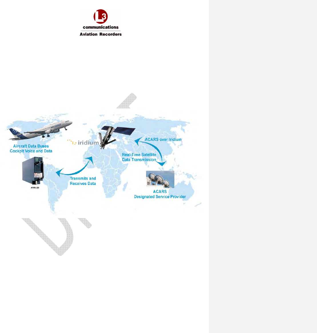
The Iridium SATCOM System provides multiple voice and data communications functions in the
aircraft. The Automated Flight Information Reporting System (AFIRS) provides a satellite voice and
data communications (SATCOM) link with the Public Switched Telephone Network (PSTN) via the
Iridium
®
satellite network. The system uses a standard ARINC 741/761 SATCOM interface to the flight
crew’s Audio Integrating System and ARINC 739A Multi-Purpose Control and Display Units (MCDUs)
in the cockpit.
Figure 2-1 –Iridium SATCOM System Operational Concept
The Iridium SATCOM System provides a dedicated safety-services data channel with the capability to
send and receive standard ACARS messages between the aircraft’s Air Traffic Service Unit (ATSU)
and a safety-services certified terrestrial service provider.
AFIRS 228S Iridium Global Communications System Installation Manual
16 July 2014 L-3 Aviation Recorders Proprietary Page 13
165E5733-00 Rev. 03
2.2 System Architecture
The Iridium SATCOM System consists of modular avionics components that can be tailored to meet
customer needs. The core system components are the Satellite Data Unit (SDU), the SDU
Configuration Module (SCM), and the Iridium Antenna (see Figure 2-2).
Figure 2-2 –Iridium SATCOM System Block Diagram
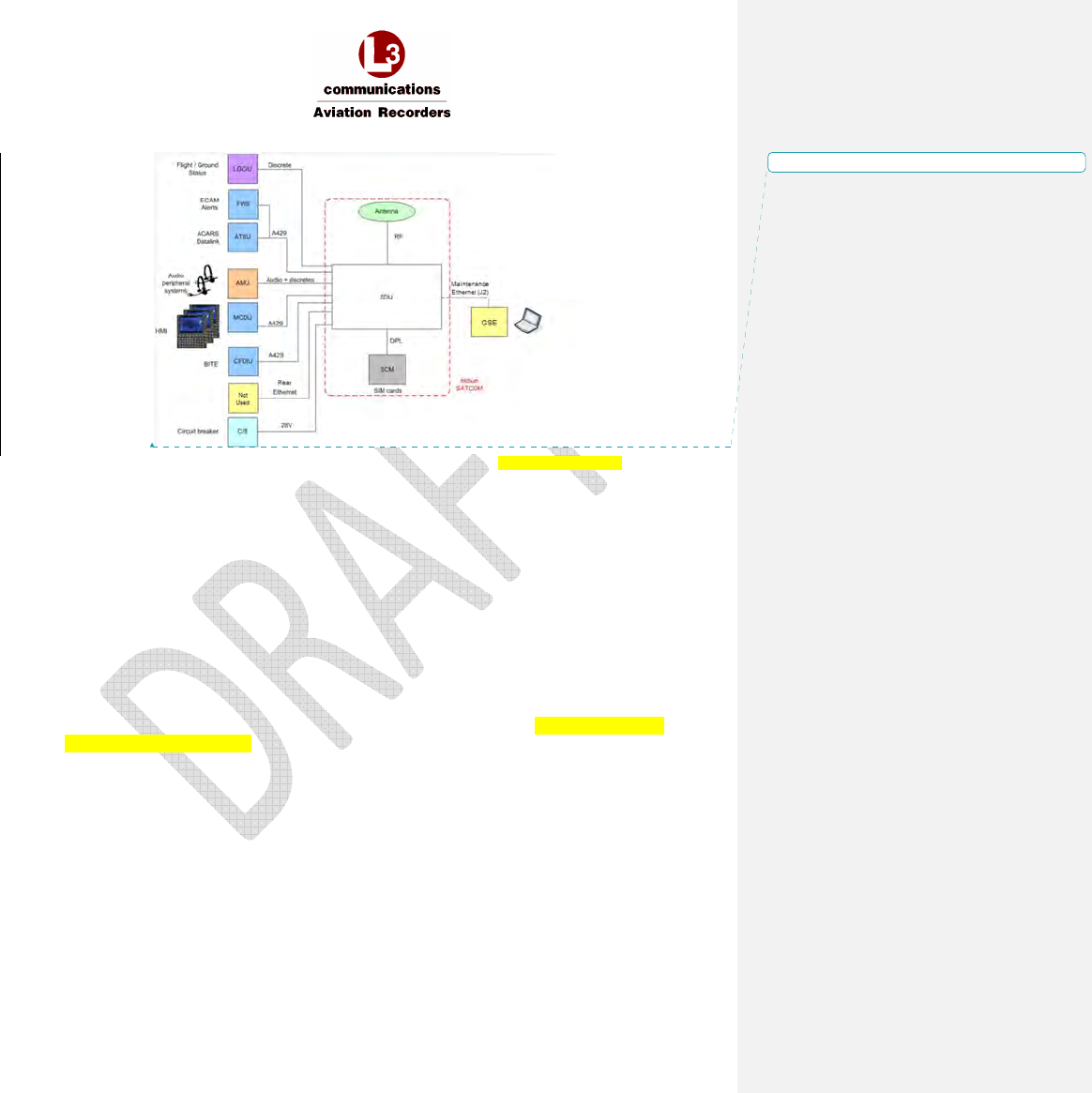
2.3 External System Interfaces
• Audio System Interface (1)
• ARINC 429 Transmitters (6) and Receivers (16)
• Discrete Outputs (8) and Inputs (16)
• Iridium Antenna (1)
• User Media Interfaces – SIM (1), CF (1)
• Maintenance Interfaces – Ethernet (1)
• Ethernet Ports (4)
• Voice Modem – Iridium 9523
• Data Modem – Iridium 9602
Figure 2-3 illustrates the interfaces that the Iridium SATCOM System provides to external aircraft
systems or to the user.
AFIRS 228S Iridium Global Communications System Installation Manual
16 July 2014 L-3 Aviation Recorders Proprietary Page 14
165E5733-00 Rev. 03
Figure 2-3 –Iridium SATCOM System External Interfaces NEED EFB GRAPHIC
• Audio System Interface (1)
This interface consists of a Microphone Input to the SDU and an Interphone Output from the SDU
to connect to a standard (DO-214) Audio Integrating System (e.g. Audio Panel) in the aircraft.
• ARINC 429 Transmitters (6) and Receivers (16)
These interfaces can be software-configured to connect to various aircraft systems to support both
the display and control functions of the Iridium SATCOM System. Typical interfaced systems
include MCDUs, ACARS ATSUs, etc.
• Maintenance Front Panel Ethernet Port J2 (1)
An RJ45 jack on the front panel provides Maintenance Port access using an Ethernet connection.
• Rear Ethernet Ports (4)
These interfaces can be used to connect to several different systems. Typical interfaced
systems include EFB, etc.One of these ports can also be used to provide a remote maintenance
port interface (e.g. in the flight compartment).
Formatted: No underline, Font color: Auto

AFIRS 228S Iridium Global Communications System Installation Manual
16 July 2014 L-3 Aviation Recorders Proprietary Page 15
165E5733-00 Rev. 03
•
Discrete Outputs (8) and Inputs (16)
Discrete inputs and outputs can be used to provide or supplement various flight crew control and
display interactions, particularly for voice functions. Discrete inputs can also be used to determine
the states of various aircraft systems when this information is not available on a databus (e.g.
Weight-on-Wheels, Doors Closed, etc.).
•
Iridium Antenna (1)
An antenna mounted on the top of the fuselage is used to communicate with both the Iridium
satellite network and the GPS satellite network.
•
User Media Interfaces – SIM (1), CF (1)
There are two types of media available for the user to insert or remove from the Iridium SATCOM
System. The SCM contains a user accessible Subscriber Identity Module (SIM) card slot for
storage of the Iridium communications management information. The SDU contains a front panel
accessible Compact Flash (CF) that must be installed to be used for system fault testing.
•
Voice Modem – Iridium 9523
Connects the Iridium System in the aircraft to the Iridium satellite for voice communication.
•
Data Modem – Iridium 9602
Connects the Iridium System in the aircraft to the Iridium satellite for ACARS data communication.
AFIRS 228S Iridium Global Communications System Installation Manual
16 July 2014 L-3 Aviation Recorders Proprietary Page 16
165E5733-00 Rev. 03
3. EQUIPMENT SPECIFICATIONS
This section describes the mechanical and environmental specifications of the components of the
Iridium SATCOM System.
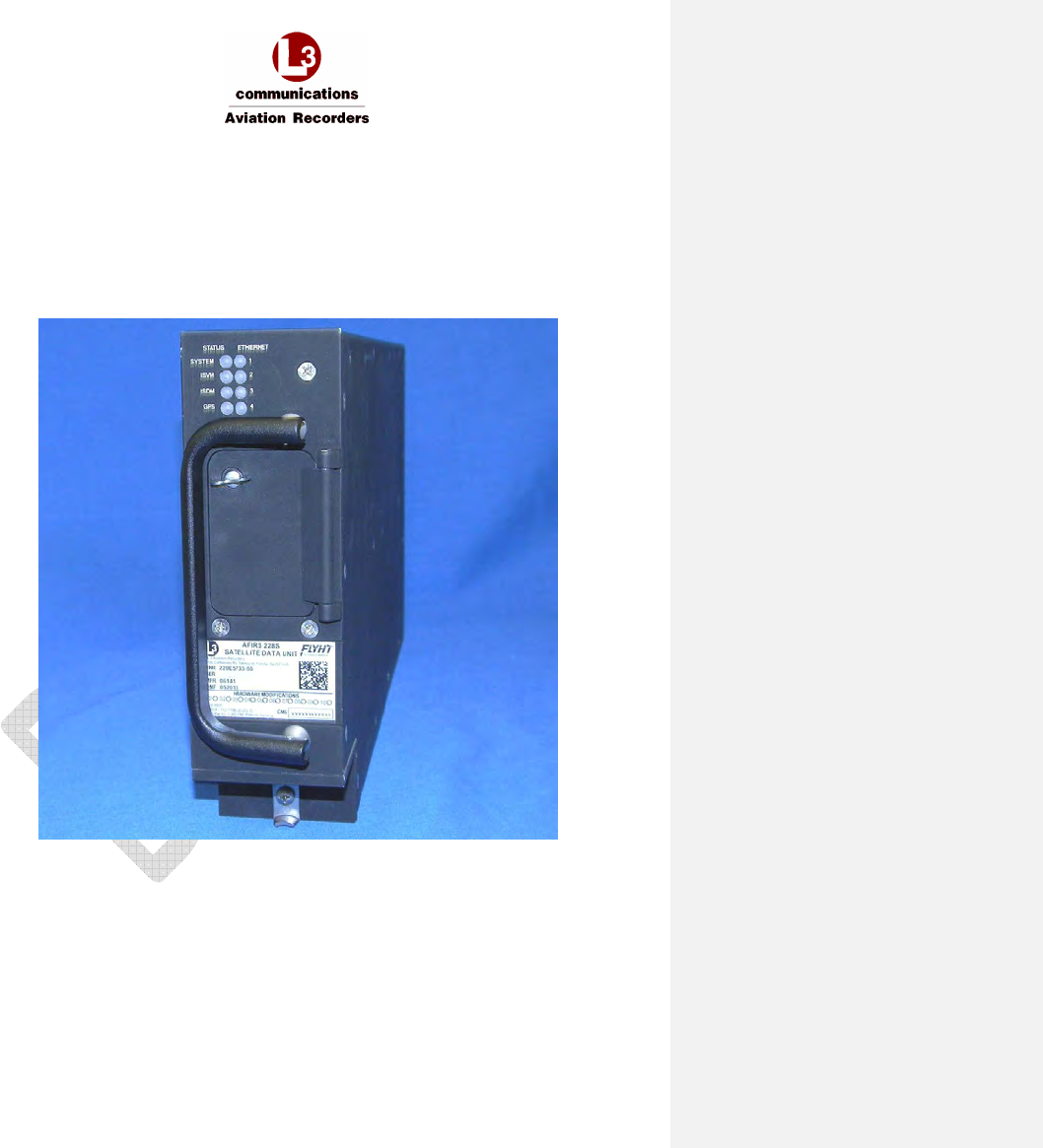
3.1 Satellite Data Unit (SDU)
The SDU is housed in an ARINC 600 2MCU enclosure designed to be mounted in a standard ARINC
600 mounting tray.
Figure 3-1 –Iridium SATCOM System Satellite Data Unit (SDU)
AFIRS 228S Iridium Global Communications System Installation Manual
16 July 2014 L-3 Aviation Recorders Proprietary Page 17
165E5733-00 Rev. 03
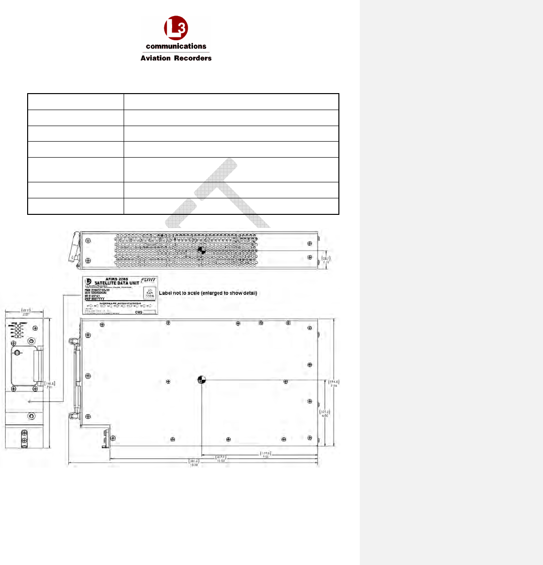
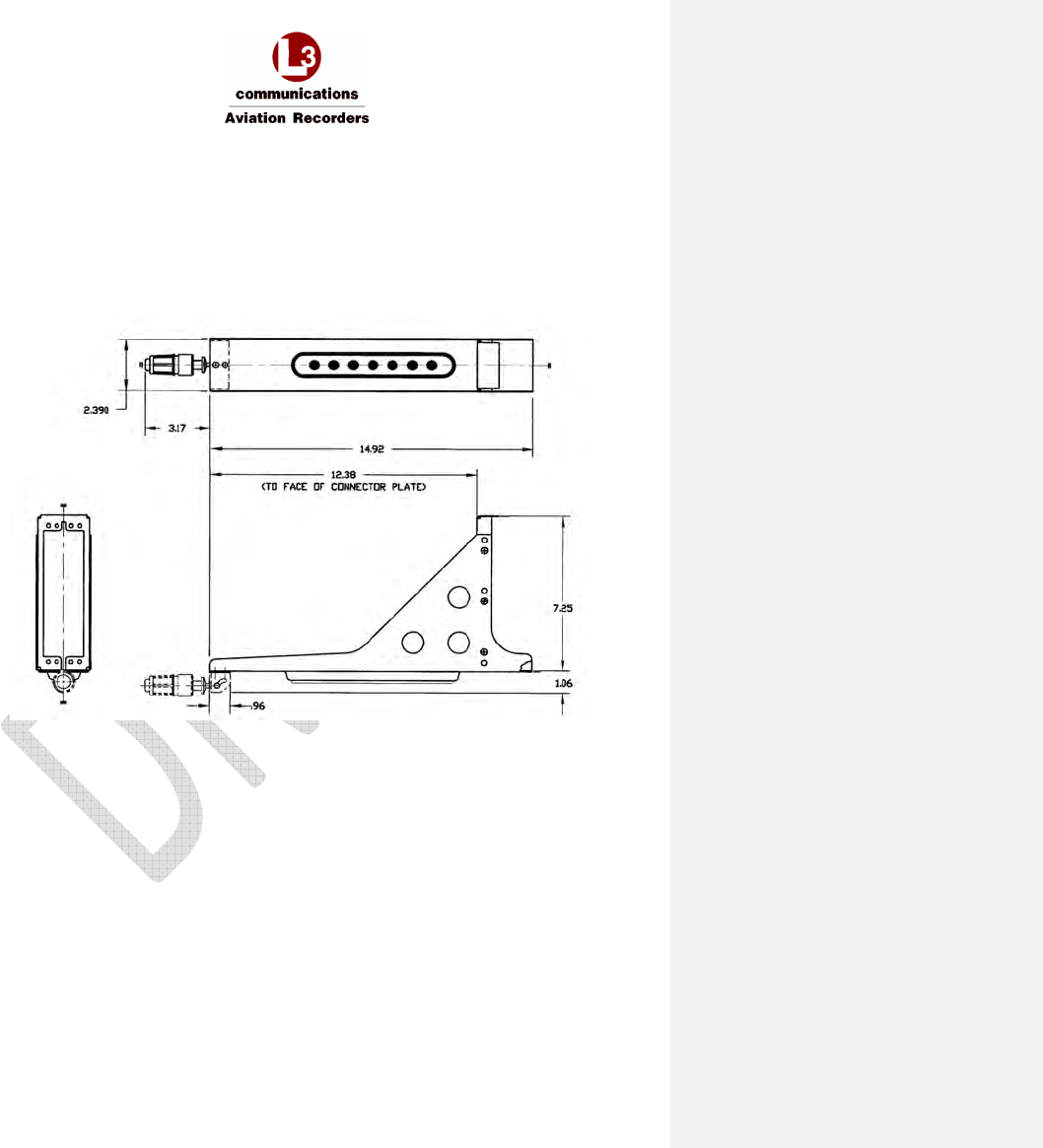
3.1.1 Mechanical Specifications
Dimensions 7.81” x 2.27” x 15.02” (198.3mm x 57.7mm x 381.5mm)
Weight 7.7 lbs. (3.49 kg) Max
Material/Finish Aluminum Alloy with Black Polyurethane Finish
Mounting ARINC 600 2MCU Mounting Tray
Rear Mating Connector Size 2 ARINC 600 Receptacle
Radiall P/N: NSXN2P201S0004
Maintenance Connector RJ45 (8P8C) Modular Connector Jack
Flash Card CompactFlash
®
(Type I or Type II)
Figure 3-2 – SDU Outline Drawing (dimensions in [millimeters] and inches)
AFIRS 228S Iridium Global Communications System Installation Manual
16 July 2014 L-3 Aviation Recorders Proprietary Page 18
165E5733-00 Rev. 03
3.1.2 Environmental Specifications –Iridium SATCOM System
Refer to Supplemental Documents for environmental testing conditions, categories and
descriptions of the SDU tests conducted.
Note:
DO-160G categories for the Iridium SATCOM System are as specified by the design.
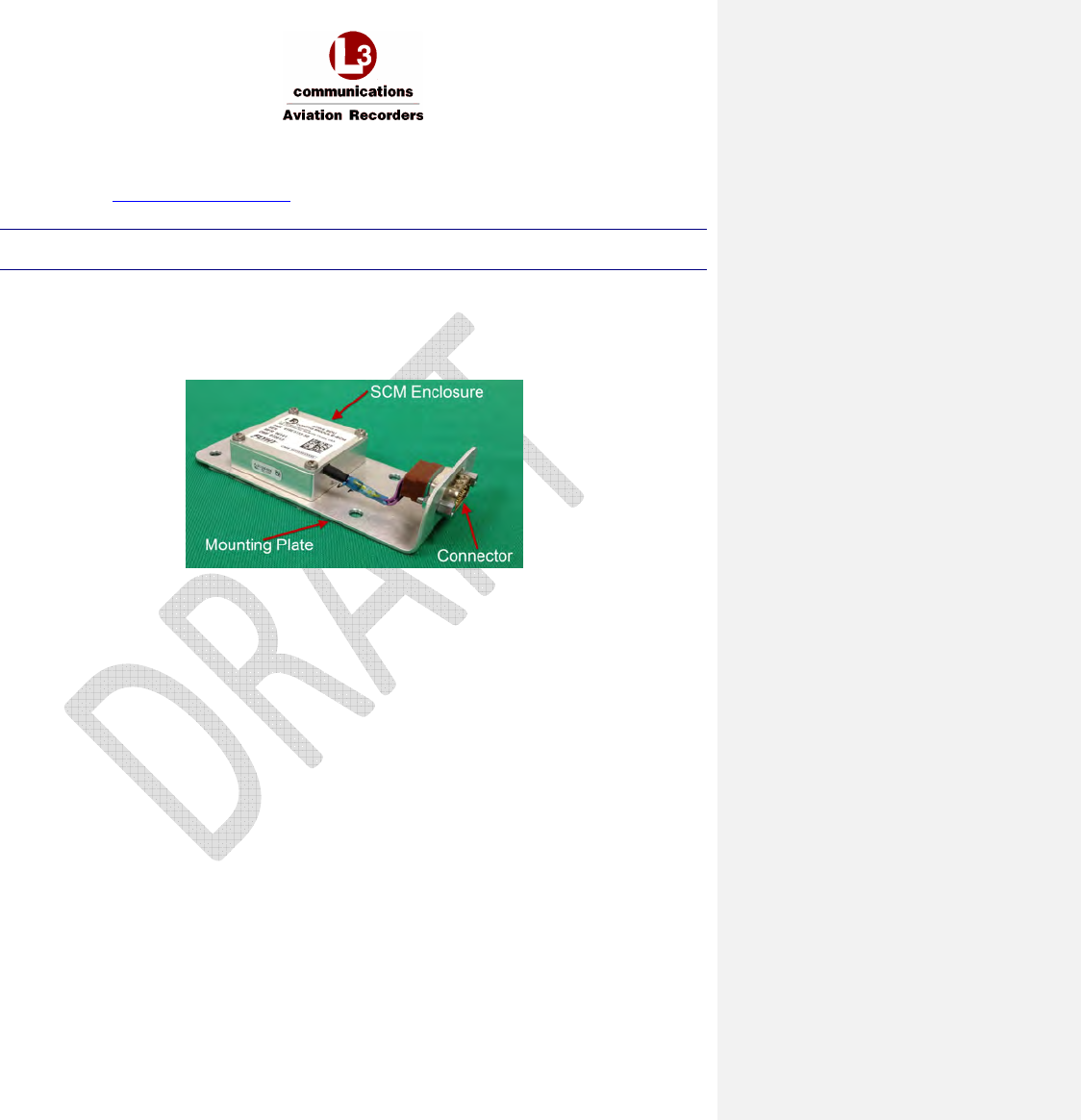
3.2 SDU Configuration Module (SCM)
The SCM is housed in a small enclosure designed to be mounted within 24” of the SDU rear
connector. Typically, the SCM will be mounted on or near the ARINC 600 mounting tray used for the
SDU. See Figure 3-6 for an outline of this component.
Figure 3-3 –Iridium SATCOM System SDU Configuration Module (SCM)
AFIRS 228S Iridium Global Communications System Installation Manual
16 July 2014 L-3 Aviation Recorders Proprietary Page 19
165E5733-00 Rev. 03
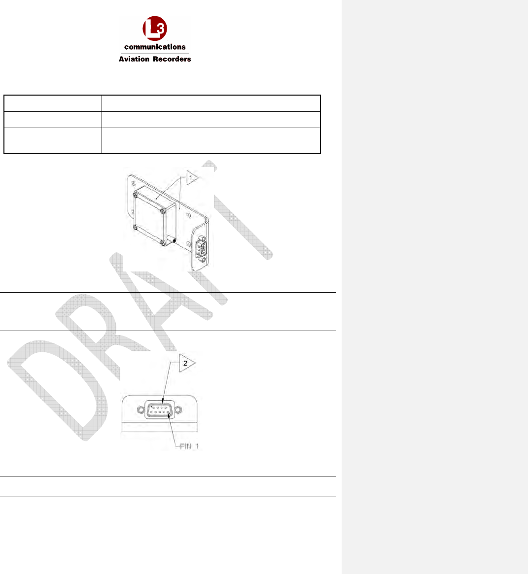
3.2.1 Mechanical Specifications
Dimensions 1.00” x 2.00” x 4.69” (25.4mm x 50.8mm x 119.1mm)
Weight 0.4 lbs. (0.18 kg) Max
Material/Finish Aluminum alloy with clear chromate per MIL-DTL-5541,
Type II, Class 3 on all surfaces
Figure 3-4 – SCM Oblique View
Note:
Resistance not to exceed 20 milli-ohms
- Between mounting plate and module
- Between mounting plate and aircraft structure
Figure 3-5 – SCM Connector View Showing Location of Pin 1
Note:
Connector is a 9-pin D-Sub, P/N ABS1145A09P03B
AFIRS 228S Iridium Global Communications System Installation Manual
16 July 2014 L-3 Aviation Recorders Proprietary Page 20
165E5733-00 Rev. 03
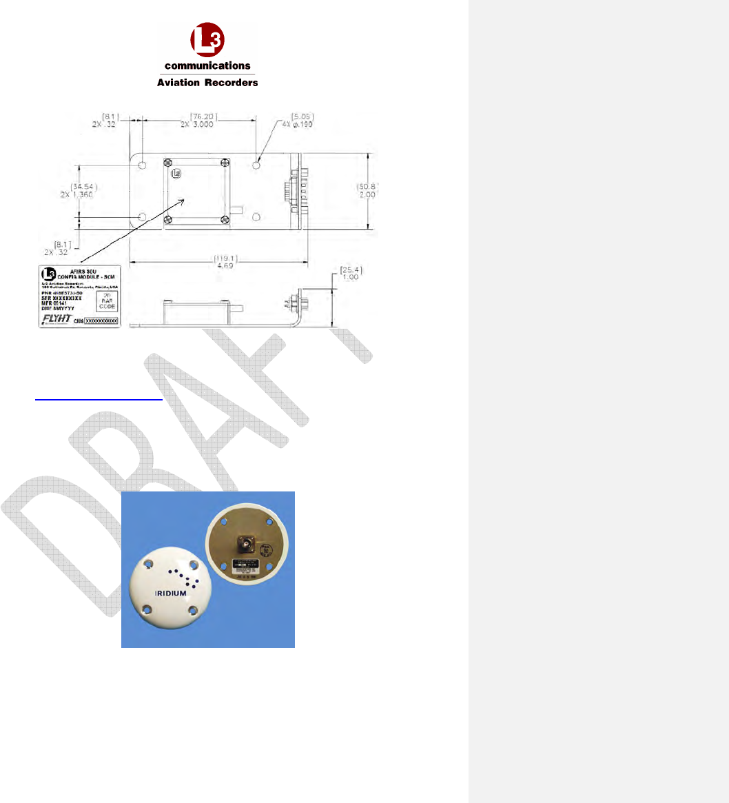
Figure 3-6 – SCM Outline Drawing (dimensions in [millimeters] and inches)
3.2.2 Environmental Specifications
Refer to Supplemental Documents for environmental testing conditions, categories, and
descriptions of the SCM tests conducted.
3.3 Iridium SATCOM System Satellite Antenna
The antenna is a Commercial Off the Shelf (COTS) unit that is mounted on the top of the aircraft’s
fuselage. It provides satellite connectivity for both the GPS and Iridium satellite systems.
Figure 3-7 –Iridium SATCOM System Antenna
AFIRS 228S Iridium Global Communications System Installation Manual
16 July 2014 L-3 Aviation Recorders Proprietary Page 21
165E5733-00 Rev. 03
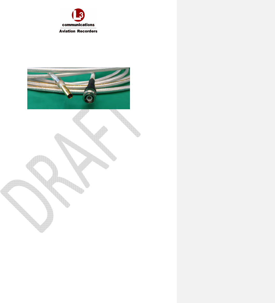
3.4 Antenna Coaxial Cable
For details on the selection and installation of the antenna coaxial cable, please see Section 4.3.3
which provides recommended coaxial cable types to be used which meet the Iridium SATCOM
System requirements.
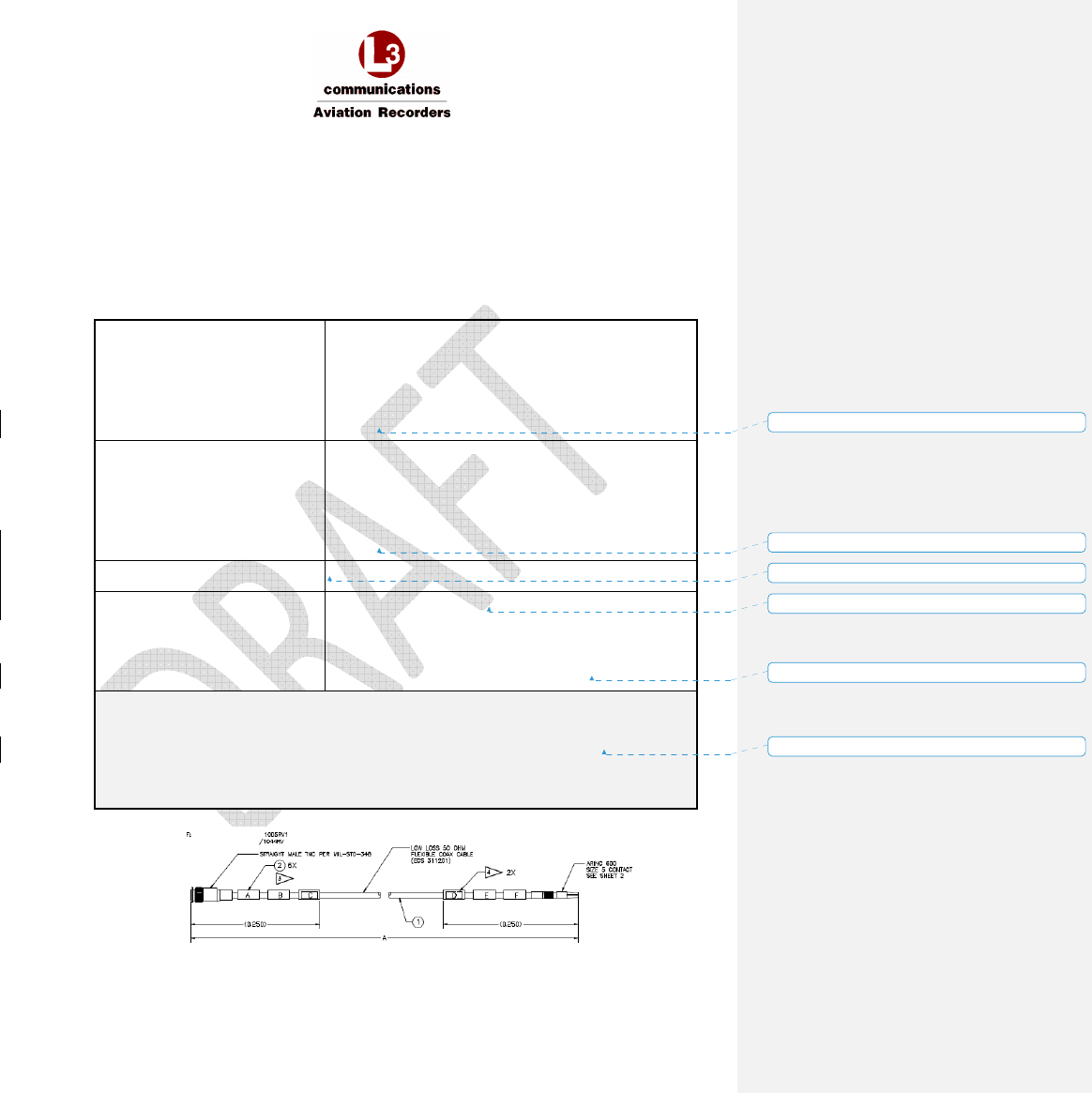
Figure 3-8 – Iridium Antenna Coaxial Cable and Connectors
AFIRS 228S Iridium Global Communications System Installation Manual
16 July 2014 L-3 Aviation Recorders Proprietary Page 22
165E5733-00 Rev. 03
3.5 Interface Specifications
3.5.1 SDU Rear Connector (J1)
Table 3-1 – J1A Top Plug (TP) Insert
A
B
C
D
E
F
G
H
J
K
1
Ethernet
1A
Tx+
Ethernet
1A
Rx+
O O
Ethernet
2B
Tx+
Ethernet
2B
Rx+
O O
Ethernet
3B
Tx+
Ethernet
3B
Rx+
2
Ethernet
1A
Rx-
Ethernet
1A
Tx-
O
Ethernet
2B
Rx-
Ethernet
2B
Tx-
O O
Ethernet
3B
Rx-
Ethernet
3B
Tx-
3 O O O O O O O O O O
4 O O O O O O O O O O
5
Ethernet
4B
Tx+
Ethernet
4B
Rx+
O O O O O O O O
6
Ethernet
4B
Rx-
Ethernet
4B
Tx-
O O O O O O O O
7 O O O O O O O O O O
8 O O O O O O O O O O
9 O O O O O O O O O O
10 O O O O O O O O O O
11 O O O O O O O O O O
12 O O O O O O O O O O
13 O O O O O O O O O O
14 O O O O O O O O O O
15 O O O O O O O O O O
AFIRS 228S Iridium Global Communications System Installation Manual
16 July 2014 L-3 Aviation Recorders Proprietary Page 23
165E5733-00 Rev. 03
Table 3-2 – J1B Middle Plug (MP) Insert
A
B
C
D
E
F
G
H
J
K
1
O O O O O O
No. 1
A429Rx
A
No. 1
A429Rx
B
No. 1
A429Tx
A
No. 1
A429Tx
B
2
Ext. 1
Mic Audio
Hi
Ext. 1
Mic Audio
Lo
Ext. 1
Audio Out
Hi
Ext. 1
Audio Out
Lo
O O O O O O
3
O O
No. 2
A429Rx
A
No. 2
A429Rx
B
No. 3
A429Rx
A
No. 3
A429Rx
B
No. 4
A429Rx
A
No. 4
A429Rx
B
No. 2
A429Tx
A
No. 2
A429Tx
B
4
O
O O O O O O O SCM
Power
SCM
Ground
5
No. 1
Discrete
Output
LGCIU 1
Discrete
Input
No. 2
Discrete
Input
No. 3
Discrete
Input
No. 4
Discrete
Input
No. 5
Discrete
Input
No. 6
Discrete
Input
No. 7
Discrete
Input
SCM
Data
SCM
Clock
6
No. 5
A429Rx
A
No. 5
A429Rx
B
No. 6
A429Rx
A
No. 6
A429Rx
B
No. 7
A429Rx
A
No. 7
A429Rx
B
No. 8
A429Rx
A
No. 8
A429Rx
B
No. 9
A429Rx
A
No. 9
A429Rx
B
7
No. 10
A429Rx
A
No. 10
A429Rx
B
No. 3
A429Tx
A
No. 3
A429Tx
B
No. 4
A429Tx
A
No. 4
A429Tx
B
No. 11
A429Rx
A
No. 11
A429Rx
B
No. 1
RS232
Com
No. 4
RS232
Com
8
No. 8
Discrete
Input
No. 2
Discrete
Output
No. 12
A429Rx
A
No. 12
A429Rx
B
No. 3
Discrete
Output
No. 9
Discrete
Input
No. 4
Discrete
Output
No. 10
Discrete
Input
No. 13
A429Rx
A
No. 13
A429Rx
B
9
No. 2
RS232
Com
No. 3
RS232
Com
No. 5
A429Tx
A
No. 5
A429Tx
B
No. 1
RS422Tx-
RS232TXD
No. 1
RS422Tx+
RS232RTS
No. 1
RS422Rx+
RS232RXD
No. 1
RS422Rx-
RS232CTS
No. 2
RS422Tx-
RS232TXD
No. 2
RS422Tx+
RS232RTS
10
No. 2
RS422Rx+
RS232RXD
No. 2
RS422Rx-
RS232CTS
No. 3
RS422Tx-
RS232TXD
No. 3
RS422Tx+
RS232RTS
No. 3
RS422Rx+
RS232RXD
No. 3
RS422Rx-
RS232CTS
No. 4
RS422Tx-
RS232TXD
No. 4
RS422Tx+
RS232RTS
No. 4
RS422Rx+
RS232RXD
No. 4
RS422Rx-
RS232CTS
11
No. 11
Discrete
Input
No. 12
Discrete
Input
No. 13
Discrete
Input
No. 14
Discrete
Input
No. 15
Discrete
Input
LGCIU
HPP
No. 5
Discrete
Output
No. 6
Discrete
Output
No. 7
Discrete
Output
No. 8
Discrete
Output
12
No. 14
A429Rx
A
No. 14
A429Rx
B
No. 6
A429Tx
A
No. 6
A429Tx
B
A717Rx
A
A717Rx
B
No. 15
A429Rx
A
No. 15
A429Rx
B
No. 16
A429Rx
A
No. 16
A429Rx
B
13
Fault
Output
N/C
Fault
Output
N/O
O O O O O O O O
14
O Chime
Output O O O O O O O O
15
O O O O O O
Phone
Ext. 2
Tip
Phone
Ext. 2
Ring
Phone
Ext. 3
Tip
Phone
Ext. 3
Ring
AFIRS 228S Iridium Global Communications System Installation Manual
16 July 2014 L-3 Aviation Recorders Proprietary Page 24
165E5733-00 Rev. 03
Table 3-3 – J1C Bottom Plug (BP) Insert
Pin Size Description
1 20 Not Used
2 12 Primary 28 VDC Power Input
3 12 Power Ground
4 20 Not Used
5 20 Not Used
6 20 Not Used
7 12 Not Used
8 16 Chassis Ground
9 16 Not Used
10 16 Not Used
11 16 Not Used
12 5 Not Used
13 5 Iridium/GPS Antenna
Figure 3-9 – SDU Connector Map
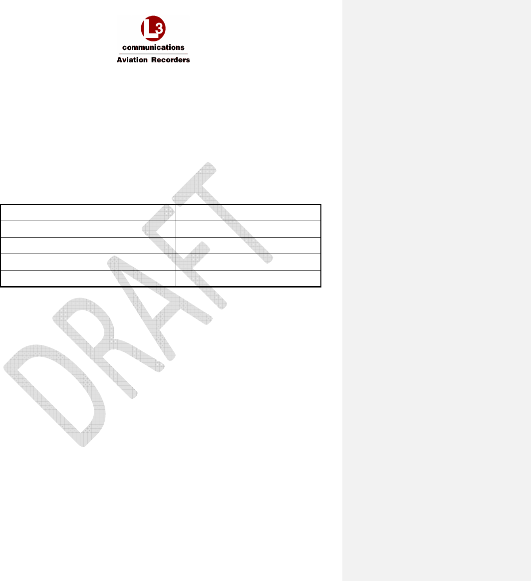
3.5.2 Power Input
The Iridium SATCOM System is powered by +28 VDC.
3.5.3 Chassis Ground
Quantity 1
Format DC Chassis Ground
For redundant chassis ground connection only.
Not to be used as a normal current carrying conductor.

AFIRS 228S Iridium Global Communications System Installation Manual
16 July 2014 L-3 Aviation Recorders Proprietary Page 25
165E5733-00 Rev. 03
3.5.4 ARINC 429 Digital Serial Bus Input
Quantity 16
Format DITS, ARINC 429 Low or high speed
Low Speed Data Rate 12.5 Kbps ± 1%
High Speed Data Rate 100 Kbps ± 1%
SSM/SDI/Data Definition Software Selectable Protocols
3.5.5 ARINC 429 Digital Serial Bus Output
Quantity 6
Format DITS, ARINC 429 Low or high speed
Low Speed Data Rate 12.5 Kbps ± 1%
High Speed Data Rate 100 Kbps ± 1%
SSM/SDI/Data Definition Software Selectable Protocols
3.5.6 Rear Ethernet Ports
Quantity 4
Format 802.3 10BASE-T/100BASE-TX, half- and full-duplex modes
(auto-negotiated)
ARINC 664P2 Physical Layer
3.5.7 Discrete Inputs
Quantity 16 Configurable
Input Impedance >10 k
Ω
Fault Current <15 mA
DIN+ Voltage Range Logic High: 7.0 – 36.0 VDC
Logic Low: 0 – 3.5 VDC
Pulse Width (Min) 100 ms
AFIRS 228S Iridium Global Communications System Installation Manual
16 July 2014 L-3 Aviation Recorders Proprietary Page 26
165E5733-00 Rev. 03
3.5.7.1 Configurable Inputs
Each configurable discrete input is individually software-configurable for the following:
• Signal Level: Open-Ground (Negative-Seeking) or Open-28V (Positive-Seeking)
• Logic Assignment: Active Low or Active High
• Function: Selected from list
Refer to Section 6.9 for additional information on use of configurable inputs.
3.5.8 Discrete Outputs
Each discrete output transitions between an “Open Circuit” (high-impedance-to-ground) and a “Closed
Circuit” (low-impedance-to-ground) state to indicate a change in output logic.
Quantity 8 Configurable
“Open Circuit” Impedance >100 kΩ
“Open Circuit” Voltage (Max) 36 VDC
“Closed Circuit” Current Limit (Min) 500 mA
Voltage Across “Closed Circuit” <1.25 V
3.5.8.1 Configurable Outputs
The discrete outputs use “Open-Closed” signal levels, where the output is either high-impedance to
ground (Open) or low-impedance to ground (Closed). Each configurable discrete output is individually
software-configurable for the following:
• Logic Assignment: Active Low (Closed) or Active High (Open)
• Function: Selected from list.
Refer to Section 6.10 for additional information on use of configurable outputs.
AFIRS 228S Iridium Global Communications System Installation Manual
16 July 2014 L-3 Aviation Recorders Proprietary Page 27
165E5733-00 Rev. 03
3.5.9 Microphone Input
Quantity 1
Format Standard DO-214 Microphone Input
Dynamic Range 20 mV to 1.5 V RMS
Input Impedance 150 Ω ± 20%
Mic. Bias (No Load) 16 ± 0.5 V
Mic. Bias Ripple <1 mV RMS in the 300 – 3400 Hz band
Sidetone Provided by System to Interphone Output
Sidetone Level Software Configurable
Audio Band Pass 300 – 3400 Hz
3.5.10 Iridium / GPS Antenna
Coaxial Cable Insertion
Loss (Max.)
3 dB @ 1626.5 MHz
3.6 Maintenance Front Panel Ethernet Port (J2)
The Iridium SATCOM System SDU provides an RJ-45 Maintenance Port connector on the front panel,
which provides for Ethernet connection to Ground Service Equipment (GSE) e.g. a laptop or Personal
Computer with a standard web browser.
3.7 SDU Configuration Module (SCM)
The SCM and antenna connect directly to the SDU. The SDU is the heart of the system and provides
all of the interfaces to other aircraft systems.
Formatted: No underline, Font color: Auto
AFIRS 228S Iridium Global Communications System Installation Manual
16 July 2014 L-3 Aviation Recorders Proprietary Page 28
165E5733-00 Rev. 03
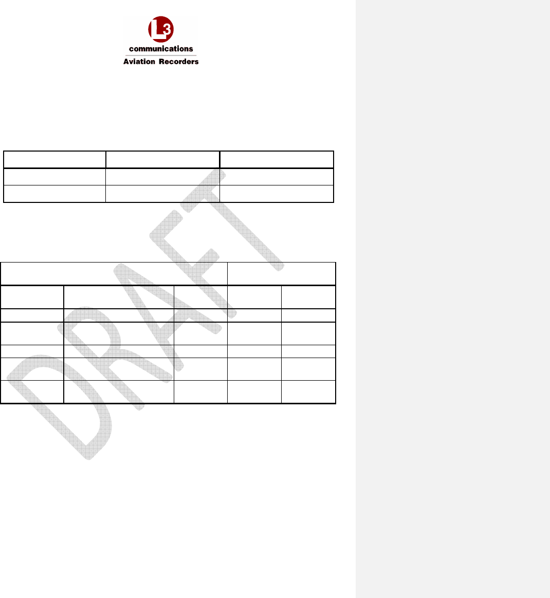
3.8 ARINC 429 Receiver Protocols
Table 3-4 – ARINC 429 Receiver Protocols – ATSU/FWC
Source: ATSU / FWC Speed: High
(Configurable)
Label Parameter Format Transmit Rate
172 ATSU Identifier Word BCD 1 s
270 ATSU Status Word and Monitoring Boolean
word
600 ms
307 SDU SAL HYB
377 ATSU Equipment Identifier BCD 1 s
ARINC 618
Block Uplink
BOP (GFI=Eh) ISO 5 N/A
ARINC 618
Block Downlink
BOP (GFI=Eh) ISO 5 N/A
Table 3-5 – ARINC 429 Receiver Protocols – MCDU
Source: ARINC 739A MCDU Speed: Low
(Configurable)
Label Parameter Format Transmit Rate
377 MCDU Identifier BCD 1 s
270 Discrete Word #1 Discrete
word
1 s
350 Maintenance Word #1 Discrete
word
1 s
307 SDU SAL HYB
AFIRS 228S Iridium Global Communications System Installation Manual
16 July 2014 L-3 Aviation Recorders Proprietary Page 29
165E5733-00 Rev. 03
3.9 ARINC 429 Receiver Activity Status
Defines the criteria the Iridium SATCOM System uses to determine if a receiver port is active. A bus is
generally declared active when four consecutive words at the specified rate are received, and
declared inactive when four consecutive samples fail.
Table 3-6 – ARINC 429 Receiver Port Monitoring
Receiver
Activity Label
Min
imum
Update Rate
ATSU / FWC 270 1 Hz
ARINC 739A MCDU 270 / 377 1 Hz
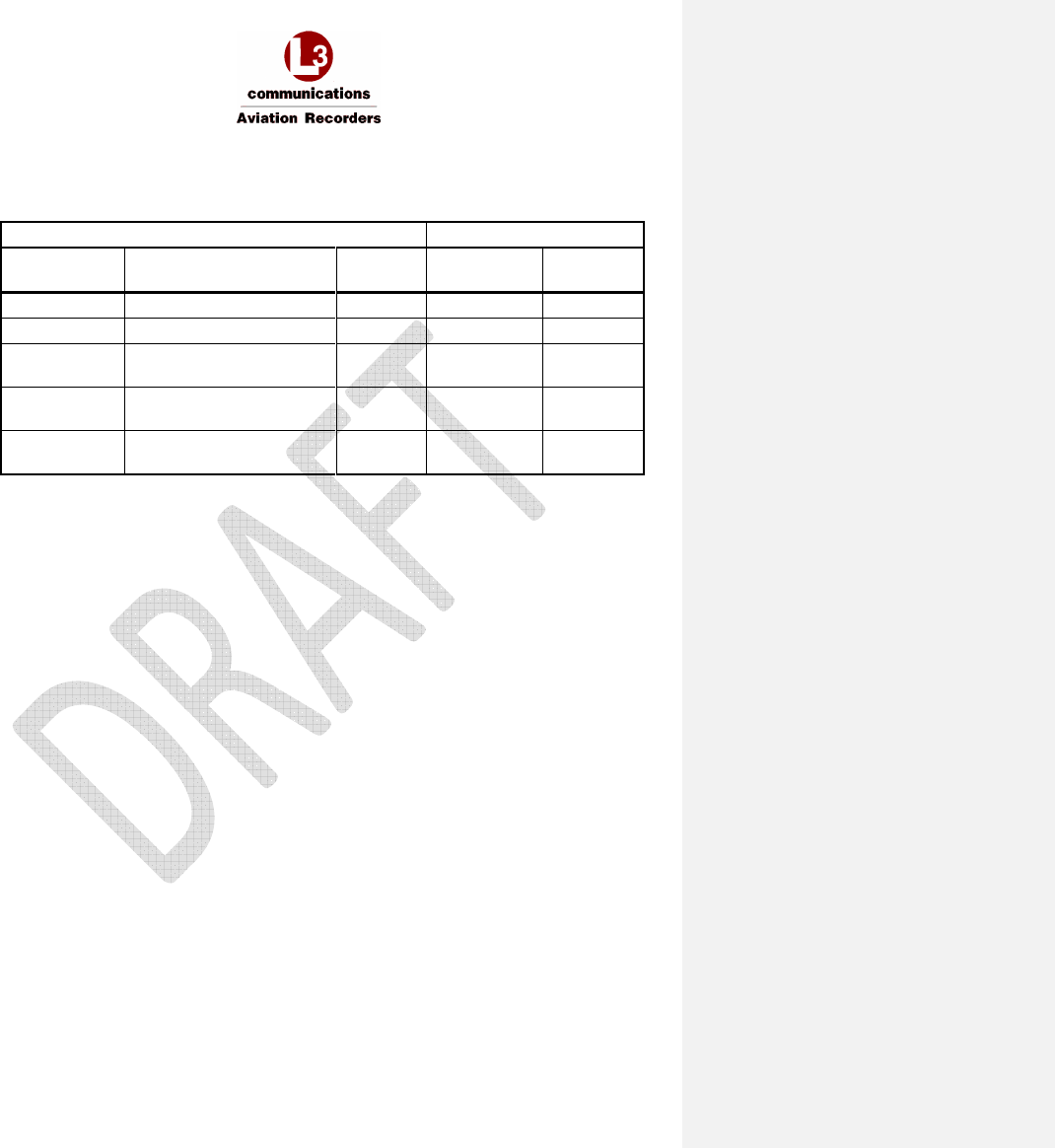
3.10 ARINC 429 Transmitter Protocols
3.10.1 From SDU to ATSU / FWC
Table 3-7 – ARINC 429 Transmitter Protocols SDU – ATSU/FWC
Destination: ATSU / FWC Speed:
High
(Configurable)
Label Parameter Format Transmit
Rate
Update Rate
172 SDU Identifier BCD 1 s –
270 SDU Status Word and
Monitoring
Boolean
word
1 s -
304 ATSU SAL HYB
ARINC 618
Block Uplink
BOP (GFI=Eh) ISO 5 N/A -
ARINC 618
Block Downlink
BOP (GFI=Eh) ISO 5 N/A -
AFIRS 228S Iridium Global Communications System Installation Manual
16 July 2014 L-3 Aviation Recorders Proprietary Page 30
165E5733-00 Rev. 03
3.10.2 From SDU to MCDU
Table 3-8 – ARINC 429 Transmitter Protocols SDU – MCDU
Destination: ARINC 739A MCDU Speed:
Low (Configurable)
Label Parameter Format Transmit
Rate
Update
Rate
172 Subsystem Identifier BCD 1 s –
377 Equipment Identifier BCD 1 s –
220 MCDU Address Label for
MCDU#1
221 MCDU Address Label for
MCDU#2
222 MCDU Address Label for
MCDU#3

AFIRS 228S Iridium Global Communications System Installation Manual
16 July 2014 L-3 Aviation Recorders Proprietary Page 31
165E5733-00 Rev. 03
THIS PAGE INTENTIONALLY LEFT BLANK
AFIRS 228S Iridium Global Communications System Installation Manual
16 July 2014 L-3 Aviation Recorders Proprietary Page 32
165E5733-00 Rev. 03
4. INSTALLATION CONSIDERATIONS
4.1 Satellite Data Unit (SDU)
The SDU is housed in an ARINC 600 2MCU enclosure designed to be mounted in a standard ARINC
600 mounting tray. Although the SDU does not require forced-air cooling, every attempt should be
made to install it in a well-ventilated area, preferably on a mounting tray that provides cooling air to
the SDU.
Figure 4-1 – Typical 2MCU Mounting Tray for the SDU
The SDU tray should be electrically bonded to the airframe (<20 milli-ohms), and installed so that
there is easy access to the front panel to facilitate replacing the flash card or connecting to the
Maintenance Port.
4.2 SDU Configuration Module (SCM)
The SCM can be mounted on or near the SDU tray within 24 inches of the SDU rear connector. The
SCM should be electrically bonded to the airframe (<20 milli-ohms). Ensure that the installation
location allows easy access to the cover should the SIM card require replacement. Refer to Figure 3-6
for the SCM mounting footprint.
AFIRS 228S Iridium Global Communications System Installation Manual
16 July 2014 L-3 Aviation Recorders Proprietary Page 33
165E5733-00 Rev. 03
4.3 Iridium Antenna System
The Iridium SATCOM System has a single combined Iridium/GPS RF connection on the rear interface
connector, which is to be connected to a single combined Iridium/GPS Antenna. The antenna system
is comprised of all the components from the rear interface connector up to, and including, the
antenna. The total gain of the antenna system must be greater than 0 dB at 1626.5 MHz (measured
at the antenna zenith).
Most Iridium antennas have a gain of +3 dBic at the zenith; therefore the maximum attenuation in the
rest of the antenna system must be less than 3 dB.
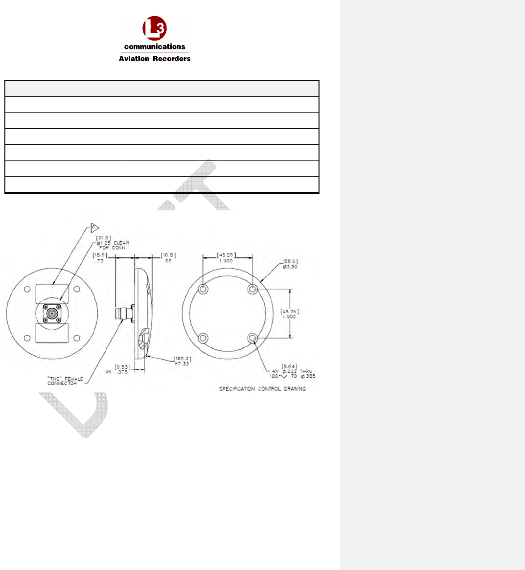
4.3.1 Antenna Specifications
The antenna is a low-profile, circular device that can be mounted directly to the aircraft fuselage, and
connects to the Iridium SDU through a coaxial cable – see Figure 3-8.
Weight (Typical) 0.170 kg (6 oz.)
Height (Typical) 16.8 mm (0.66 inches)
Diameter (Typical) 89 mm (3.5 inches)
Manufacturer’s Reference
Documentation
Drawing 009E5733-00, Revision B
Iridium Antenna – Passive, 1565 – 1626.5 MHz
RHCP – see Figure 4-2.
Iridium SATCOM System Supplier Equipment
Specification: Doc. No. 905-E5750-07, Revision N
Environmental
The Iridium SATCOM System antenna meets the environmental requirements of RTCA
DO-262A, where applicable, as referenced in Doc. No. 905-E5809-42, Revision C.
Testing was performed to DO-160F, MIL-STD-810, EN-60068, ISO-2669, and the
applicable ABDs, unless otherwise noted.
Temperature -55° C (-67° F); to +85° C (+185° F)
Altitude -100 to +55,000 FT
Vibration 10 Gs (DO-160D/E F2-AB)
AFIRS 228S Iridium Global Communications System Installation Manual
16 July 2014 L-3 Aviation Recorders Proprietary Page 34
165E5733-00 Rev. 03
E
lectrical
Frequency 1616.0 – 1626.5 MHz
VSWR
≤
1.5:1
Impedance 50-Ohms
Polarization RHCP
Axial Ratio
≤
3.0 db @ zenith
Power Handling 60 Watts CW
Figure 4-2 - Iridium Antenna, Outline and Dimensions
AFIRS 228S Iridium Global Communications System Installation Manual
16 July 2014 L-3 Aviation Recorders Proprietary Page 35
165E5733-00 Rev. 03
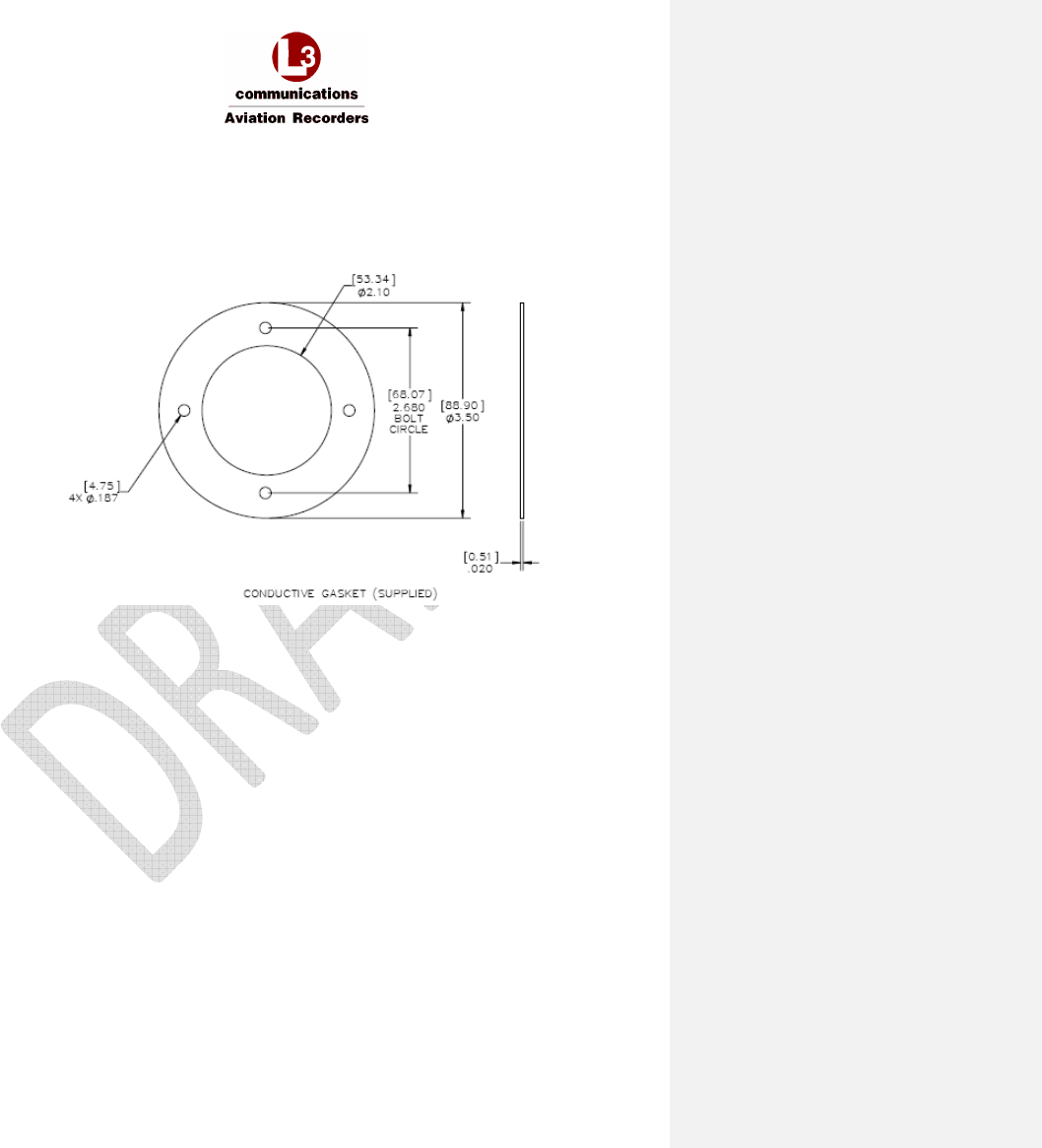
4.3.2 Antenna Mounting
A .020 thick conductive gasket is provided. L-3 recommends using four screws (MS24693-C274) for
mounting the Iridium Antenna.
Figure 4-3 - Iridium Antenna, Gasket
AFIRS 228S Iridium Global Communications System Installation Manual
16 July 2014 L-3 Aviation Recorders Proprietary Page 36
165E5733-00 Rev. 03
4.3.3 Coaxial Antenna Cable
The Iridium SATCOM System uses an RF cable designed to cover the frequency range from 1565
MHz to 1626.5 MHz for Iridium transmit / receive operations and GPS reception. It is a low-loss,
aircraft-grade cable that will be mounted in the aircraft fuselage. This cable provides the
interconnection between the Iridium SATCOM System Satellite Data Unit and the Iridium Antenna.
One end of the coaxial cable has an ARINC Size 5 coaxial contact installed and the other end has a
TNC male connector.
Specifications
Weight (Typical)
•
024E5733-01 - 1.64 kg (57.85 oz)
•
024E5733-02 – 1.50 kg (52.91 oz)
•
024E5733-03 – 1.47 kg (51.85 oz)
•
024E5733-04 – 1.68 kg (59.26 oz)
Length (Typical)
•
024E5733-01 – 11.30 m (445.0 inches)
•
024E5733-02 – 10.20 m (402.0 inches)
•
024E5733-03 – 9.95 m (392.0 inches)
•
024E5733-04 – 11.56 m (455.1 inches)
Diameter (Typical) 8.1 mm (0.32 inches)
Manufacturer’s Reference
Documentation
Drawing 024E5733-00, Revision D
Iridium Antenna Coax Cable – see Figure 4-4.
Iridium SATCOM System Supplier Equipment
Specification: Doc. No. 905-E5750-07, Revision N
Environmental
The Iridium SATCOM System coaxial cable meets the environmental requirements of
RTCA DO-262A, where applicable, as described in Doc. No. 905E5836-42 Revision B.
Testing was performed to DO-160F, EN 4604, EN 3475, and the applicable ABDs,
unless otherwise noted.
Figure 4-4 – Iridium Antenna Coaxial Cable
Formatted: No underline, Font color: Auto
Formatted: No underline, Font color: Auto
Formatted: No underline, Font color: Auto
Formatted: No underline, Font color: Auto
Formatted: No underline, Font color: Auto
Formatted: No underline, Font color: Auto

AFIRS 228S Iridium Global Communications System Installation Manual
16 July 2014 L-3 Aviation Recorders Proprietary Page 37
165E5733-00 Rev. 03
THIS PAGE INTENTIONALLY LEFT BLANK

AFIRS 228S Iridium Global Communications System Installation Manual
16 July 2014 L-3 Aviation Recorders Proprietary Page 38
165E5733-00 Rev. 03
5. SATCOM INSTALLATION MATERIALS
In addition to the Iridium SATCOM System LRUs (SDU and SCM), the materials described in this
section are generally required as part of a typical Iridium SATCOM System installation.
Note:
The system integrator is responsible to ensure that all installation materials used meet the regulatory
requirements for the intended aircraft installation environment.
5.1 Required Materials
• ARINC 600 2MCU mounting tray
• ARINC 600 Size 2 connector, with contacts
• ARINC 600 ground block, with contacts
• Iridium antenna
• Antenna coaxial cable(s)
• System interface wiring

AFIRS 228S Iridium Global Communications System Installation Manual
16 July 2014 L-3 Aviation Recorders Proprietary Page 39
165E5733-00 Rev. 03
THIS PAGE INTENTIONALLY LEFT BLANK
AFIRS 228S Iridium Global Communications System Installation Manual
16 July 2014 L-3 Aviation Recorders Proprietary Page 40
165E5733-00 Rev. 03
6. SYSTEM INTERFACE WIRING
6.1 General
All wire types and installation practices must comply with the requirements for the aircraft. Unless
otherwise noted, minimum wire size is 22 AWG for standard copper wire or 24 AWG for high-strength
copper alloy wire.
Terminate all shields at ground block or ground stud on SDU tray. Keep shield drains and unshielded
conductor lengths as short as practicable (<3”).
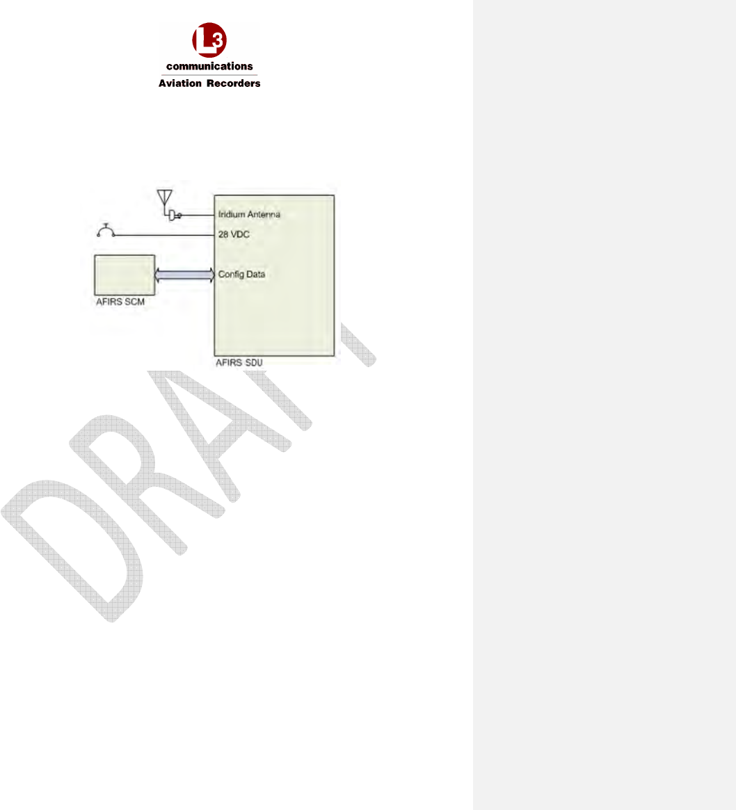
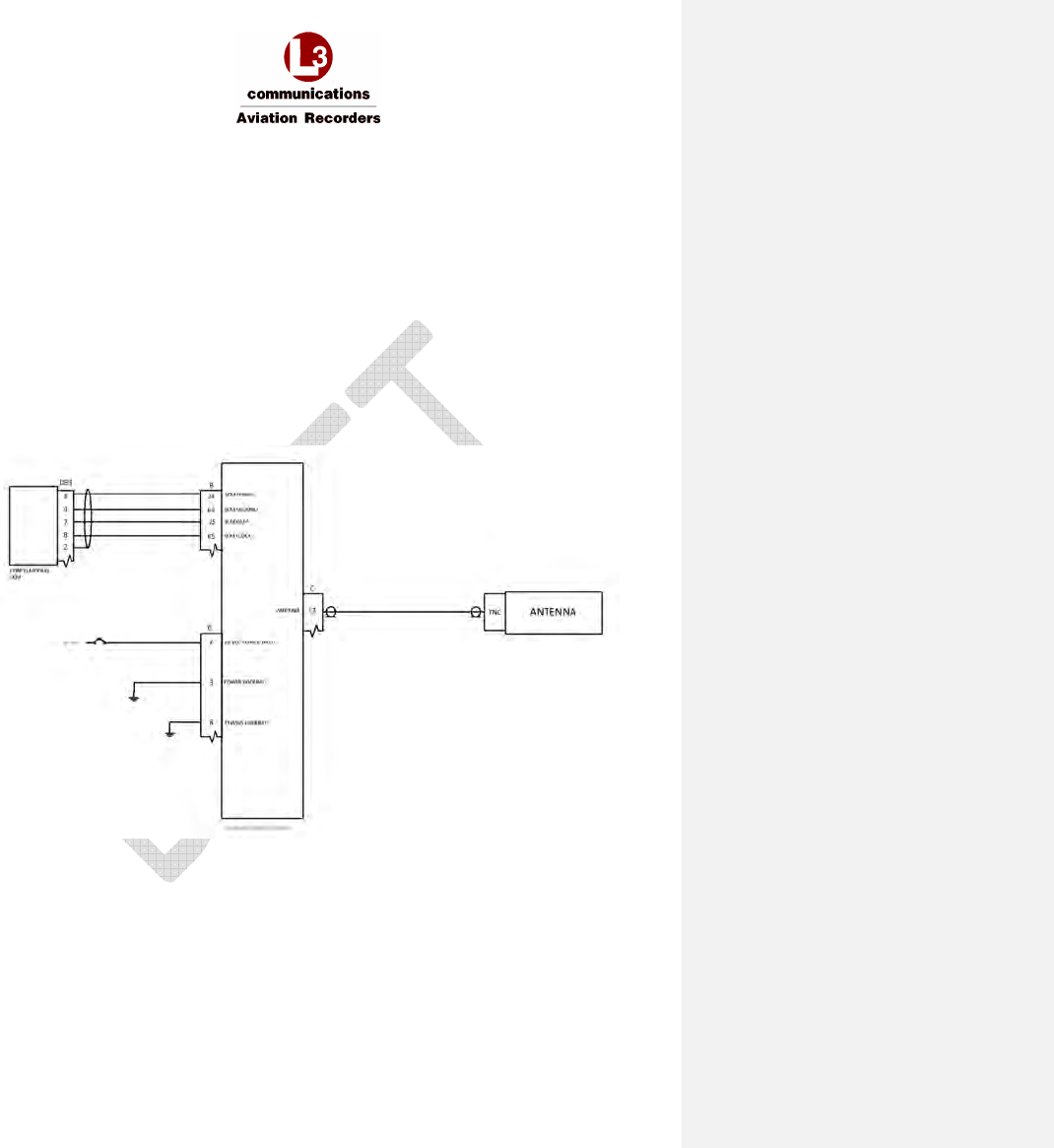
6.2 Primary Power, Antenna, and SCM
The primary power, antenna, and SCM connections in Figure 6-1 are required for all Iridium SATCOM
System installations. The system will start, and continue to operate, whenever power (20.5 – 32.2 VDC)
is available at the Primary Power Input pin (J1C-2).
Figure 6-1 – Primary Power, Antenna, and SCM Interface

AFIRS 228S Iridium Global Communications System Installation Manual
16 July 2014 L-3 Aviation Recorders Proprietary Page 41
165E5733-00 Rev. 03
6.3 ARINC 429 Interfaces
The Iridium SATCOM System has 16 ARINC 429 receive ports and 6 ARINC 429 transmit ports. Each
port is software-configurable for high or low speed, and the receive ports are also individually
software-configurable for odd, even, or no parity checking. The transmit ports always transmit odd
parity.
6.3.1 Receiver Protocols
Each of the ARINC 429 receivers can be configured in software for the proper protocol of the external
aircraft system to which it is interfaced. Once a protocol (except “None”) is selected for any given
receive port, it is no longer available for assignment to any other port. When an input is not connected
to an active system (e.g. no connection, or wiring provisions only are installed), the port should be
configured as “None” to avoid triggering bus inactivity faults.
•
None
•
ACARS 1
•
ACARS 2
•
A739 MCDU 1
•
A739 MCDU 2
•
A739 MCDU 3
See Section 0 for the label specifications for each receiver protocol.
6.3.2 Transmitter Protocols
Each of the ARINC 429 transmitters can be configured in software for the proper protocol of the
external aircraft system to which it is interfaced. Once a protocol (except “None”) is selected for any
given port, it is no longer available for assignment to any other port.
•
None
•
ACARS
•
A739 MCDU
See Section 3.10 for the label specifications for each transmitter protocol.
AFIRS 228S Iridium Global Communications System Installation Manual
16 July 2014 L-3 Aviation Recorders Proprietary Page 42
165E5733-00 Rev. 03
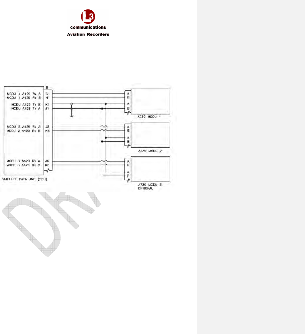
6.4 MCDU
If an ARINC 739A MCDU is installed:
• MCDU 1 should be connected to ARINC 429 Tx 1 and ARINC 429 Rx 1
• MCDU 2 and 3 can be connected to any ARINC 429 Rx port from 2-16
(Ports 2 and 3 are used in Figure 6-2)
Figure 6-2 – MCDU Interface
AFIRS 228S Iridium Global Communications System Installation Manual
16 July 2014 L-3 Aviation Recorders Proprietary Page 43
165E5733-00 Rev. 03
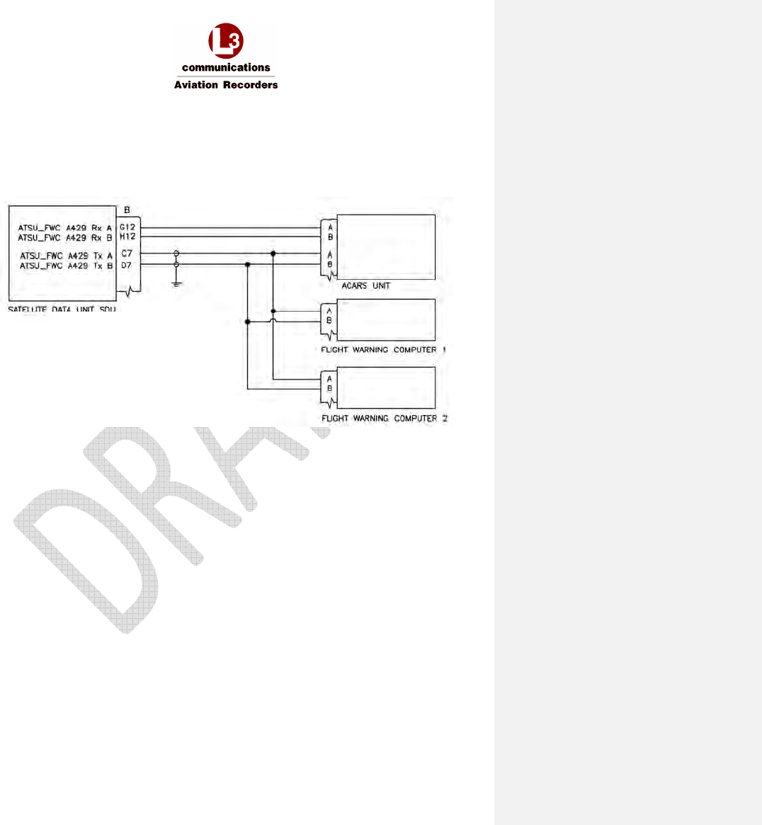
6.5 ACARS ATSU
The ACARS ARINC 429 Tx interface provides safety-services data functionality for the Iridium
SATCOM System. It is recommended that if the ACARS ATSU ARINC 429 Rx connection will not be
used, that the wires be capped and stowed near the connectors as shown. Any Rx port from 2 to 16
may be used (ARINC 429 Rx port 4 is used in Figure 6-3).
Figure 6-3 – ACARS ATSU Interface
AFIRS 228S Iridium Global Communications System Installation Manual
16 July 2014 L-3 Aviation Recorders Proprietary Page 44
165E5733-00 Rev. 03
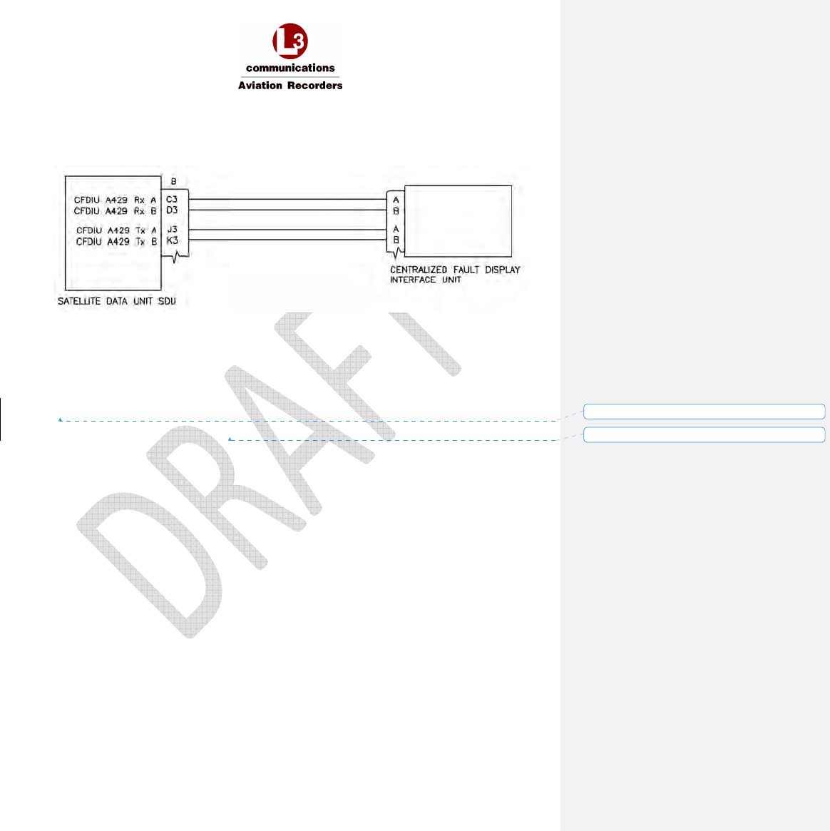
6.6 CFDIU Interface
The SDU communicates with the Centralized Fault Display Interface Unit (CFDIU) over two ARINC
429 Low Speed busses, (1) input and (1) output as shown in Figure 6-4.
Figure 6-4 – CFDIU Interface
6.7 Date, Time, and Position
The Iridium SATCOM System’s internal GPS provides date, time, and position information to be used
in various ways; for example, attaching information tags to various reports and events.
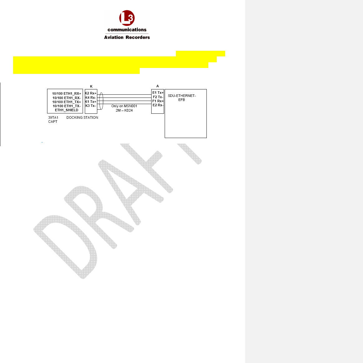
6.8 Rear Ethernet Ports
The Iridium SATCOM System has four rear Ethernet ports (see Figure 6-5) that should be set to
“none”. Each port can auto-negotiate the best speed (10/100) and mode (full/half duplex).
A 4-conductor Ethernet cable must be used. The rear connector pin layout provides slightly better
noise immunity with a star-quad cable construction, but a twisted-pair cable construction can generally
also be used.
• For star-quad cables, the conductor lay order should be maintained without crossing the
conductors when terminating.
Examples: PIC P/N E51424 and ECS P/N 422404
• For twisted-pair construction, the conductor twists should be maintained right up to the rear
connector.
Examples: PIC P/N E40424 and ECS P/N 922404
In either case, the best noise immunity is obtained by keeping the strip length of the shield as short as
physically possible, preferably <0.25 inches.
Each of the Ethernet ports can be configured in software for the proper protocol of the external aircraft
system to which it is interfaced. Below is a list of the available protocols.
• None
• Not Monitored
• Monitored
Unused Ethernet ports should be configured as “None.” A “Monitored” port is one where the system
expects an active link and it will generate a fault if the Ethernet link to the external system is not
Formatted: No underline, Font color: Auto
Formatted: No underline, Font color: Auto, Not Highlight
AFIRS 228S Iridium Global Communications System Installation Manual
16 July 2014 L-3 Aviation Recorders Proprietary Page 45
165E5733-00 Rev. 03
available. For example, if the SDU is connected by Ethernet to a Class 2 EFB that is routinely
turned off and stowed for take-off and landing, the port should be configured as “Not
Monitored” or the system will generate a fault whenever the EFB is disconnected.
REPLACE WITH UPDATED DIAGRAM FROM AIRBUS – This was NOT updated when the Non-
EFB document was because only the non-EFB drawing was created at that time.
Figure 6-5 – Rear Ethernet Ports
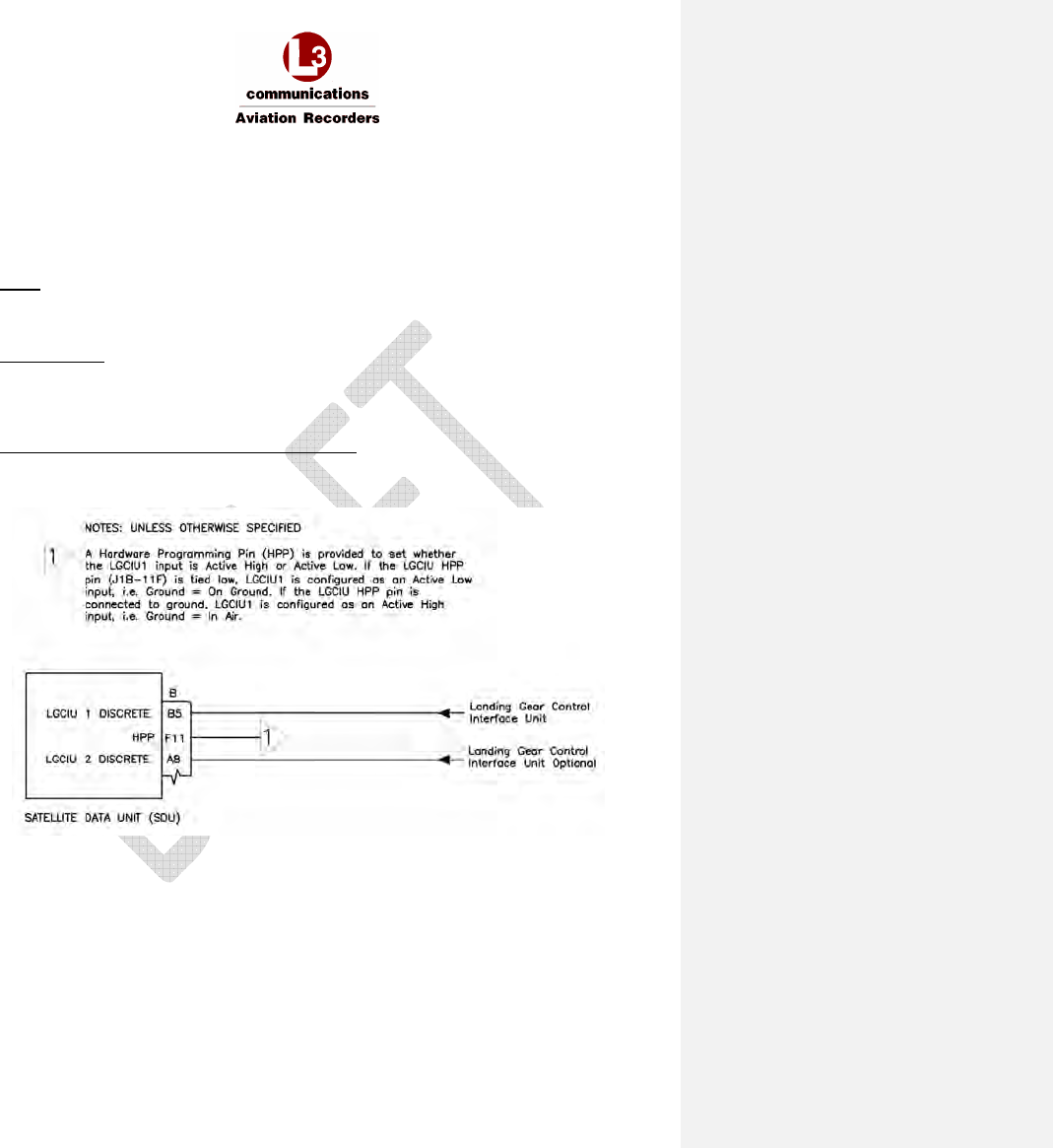
6.9 Discrete Inputs
The Iridium SATCOM System has 16 Discrete Inputs, of which 14 are software-configurable for Open-
Ground or Open-28V signaling levels, Active High or Active Low logic, and the assigned function.
6.9.1 Landing Gear Control Interface Unit (LGCIU) Input
Discrete input no. 1 (Din 1) is dedicated for use as a Landing Gear Control Interface Unit (LGCIU1)
input. When there is only one LGCIU input (i.e. the LGCIU2 function is not assigned to a discrete
input; see Section 6.9.2) and the LGCIU1 input transitions to the active state, the system is signaled
that the aircraft is on the ground, and the inactive state indicates that the aircraft is in the air.
LGCIU1 (Din 1) is only an Open-Ground input; it cannot be configured as an Open-28V input. A
Hardware Programming Pin (HPP) is provided to set whether the LGCIU1 input is Active High or
Active Low. If the LGCIU HPP pin (J1B-11F) is tied low, LGCIU1 is configured as an Active Low input,
i.e. Ground = On Ground. If the LGCIU HPP pin is connected to ground, LGCIU1 is configured as an
Active High input, i.e. Ground = In Air.
If one of the configurable discrete inputs is configured for the LGCIU2 function (see Section 6.9.2), the
following logic is used to determine the aircraft’s Air-Ground status:
• When the LGCIU1 discrete input is in the active state (as configured by the LGCIU HPP
strapping) and the LGCIU2 discrete input is in the active state (as defined by the ICT setting
for the discrete input configured as “LGCIU 2”), the aircraft is considered as “on the ground.”
• When any of the LGCIU discrete inputs are in the inactive state, the aircraft is considered as
“in the air.”
6.9.2 Function Assignment
The discrete inputs are software configurable. Once a function is selected for any given input, it is no
longer available for assignment to any of the other inputs. See Figure 6-6.
AFIRS 228S Iridium Global Communications System Installation Manual
16 July 2014 L-3 Aviation Recorders Proprietary Page 46
165E5733-00 Rev. 03
The Mic On and Call Light functions are used in conjunction with the Extension 1 audio interface and
are discussed in Section 6.11.1.1 below.
• Discrete input no. 1 (Din 1) is dedicated as a LGCIU input.
• Only discrete inputs Din 2 through Din 15 are software-configurable.
• Discrete input no. 16 (Din 16) is dedicated as “aircraft on ground” (LGCIU HPP).
None
When an input is not connected to an active system (e.g. no connection, or wiring provisions
only are installed), configure the input as “None.”
System Reset
The System Reset discrete input, when configured, will reset the system only after an inactive
to active transition. The system will reset only once even if the discrete input is left active. The
System Reset function is independent of the “In-Air” or “On-Ground” status of the aircraft.
Landing Gear Control Interface Unit 2 (LGCIU2)
A second Landing Gear Control Interface Unit input may optionally be provided to the AFIRS
system. Refer to Section 6.9.1 for the logic used when a LGCIU2 input is provided.
Figure 6-6 – Discrete Input Interfaces

AFIRS 228S Iridium Global Communications System Installation Manual
16 July 2014 L-3 Aviation Recorders Proprietary Page 47
165E5733-00 Rev. 03
6.10 Discrete Outputs
The Iridium SATCOM System has 8 configurable discrete outputs, each of which is software-
configurable for Active High or Active Low logic and the assigned function. The discrete outputs use
“Open-Closed” signal levels, where the output is either high-impedance to ground (Open) or low-
impedance to ground (Closed).
Once a function (except “None”) is selected for any given output, it is no longer available for
assignment to any of the other outputs.
6.11 SATCOM
This section describes the interface and integration requirements for the Iridium SATCOM System
with an Audio Integrating System.
6.11.1 Audio Integrating System
Extension 1 is generally intended to be connected to the aircraft’s audio integrating system for flight
crew use. The interfaces required to fully support this functionality vary significantly depending on the
design of the audio integrating system. Generally, the MCDUs are used for control and display of the
SATCOM functions for Extension 1.
6.11.1.1 Audio Discrete Signals
There is one discrete input and one discrete output that can be used to support the integrated audio
interface.
Mic On Input
The Mic On function is dedicated as a Latched ACP mode; therefore, Voice Extension 1
(Mic/Phone input) will answer an incoming call when the Mic On input transitions to the active
state. Once a call is in progress, the microphone audio channel will function as long as the Mic
On input is in the active state. If a call is in progress and the Mic On input toggles to the
inactive state, the call will be terminated. For outgoing calls when the Mic On input is
configured for Latched ACP, the function is dependent on which control source is configured
for Extension 1. When an MCDU is the Extension 1 dialing control, setting the “Mic On” input
to the active state will initiate the dialing process using the phone number preselected on the
MCDU.
Call Light Output
The Call List Output is Software configurable for either steady or flashing lights.
• Incoming Call is Ringing = Call Light output will transition to the active state, either in a
steady state or flashing at approximately a 1 Hz rate.
• Call is Answered = Call Light output remains active in the steady state as long as the
call is in progress.
• Call is Terminated = Call Light output will go inactive.
AFIRS 228S Iridium Global Communications System Installation Manual
16 July 2014 L-3 Aviation Recorders Proprietary Page 48
165E5733-00 Rev. 03
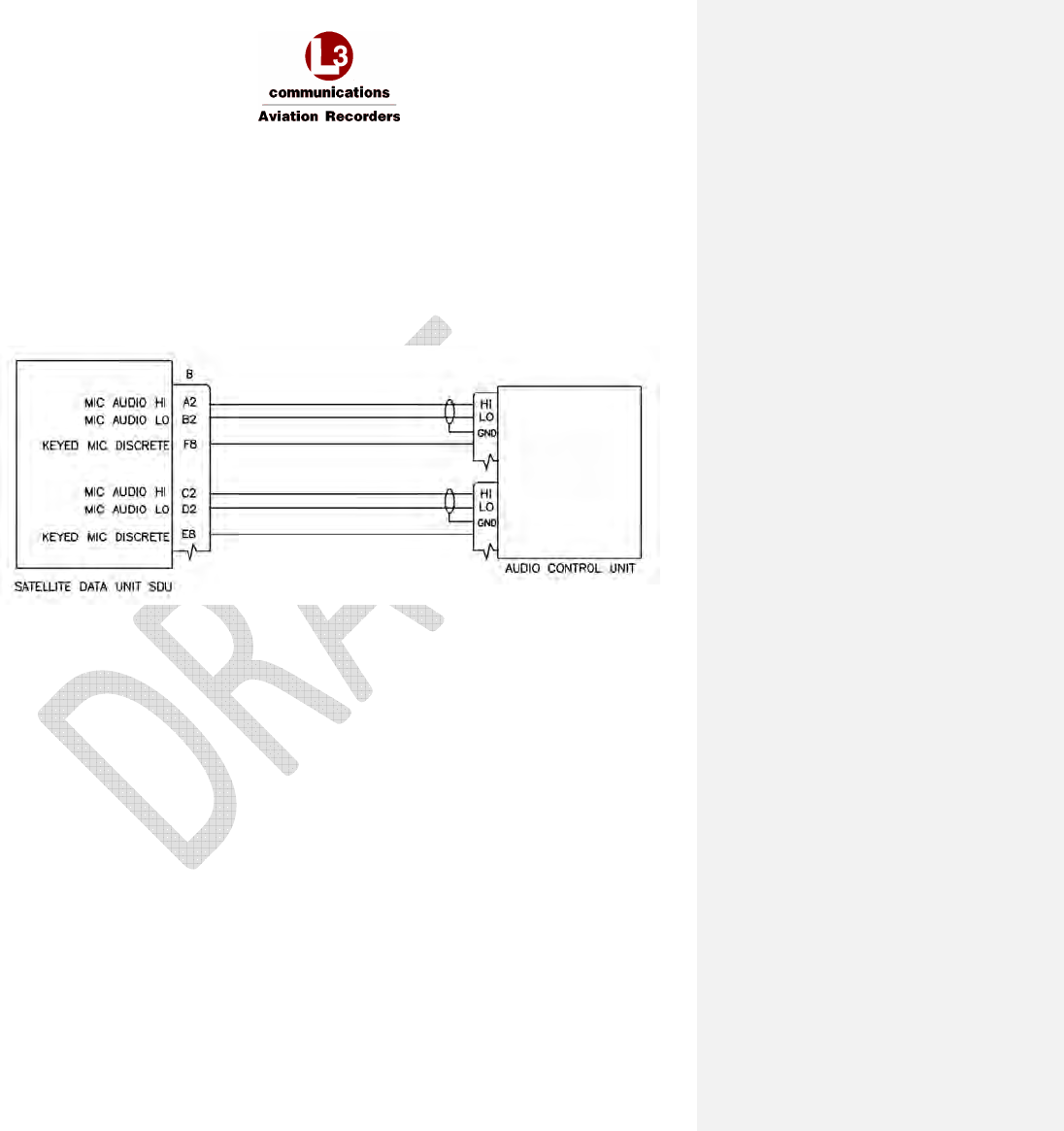
6.11.1.2 Latched ACP Configuration
If the Audio Integrating System provides a latched Mic On output, the following interface can be used.
When an incoming call is ringing and the SATCOM switch on the Audio Control Panel is pressed, the
call will be answered and microphone audio will always be live. The SATCOM switch on the Audio
Control Panel is pressed a second time to end the call. Calls cannot be answered and terminated on
the MCDU screen in this configuration.
The following diagram also shows how the Call Light output can be interfaced to an Audio Integrating
System that provides SATCOM visual and aural call indications. In this case, a Call Light, Chime and
Chime Reset switch are not required.
Figure 6-7 – Latched ACP Audio Interface

AFIRS 228S Iridium Global Communications System Installation Manual
16 July 2014 L-3 Aviation Recorders Proprietary Page 49
165E5733-00 Rev. 03
THIS PAGE INTENTIONALLY LEFT BLANK
AFIRS 228S Iridium Global Communications System Installation Manual
16 July 2014 L-3 Aviation Recorders Proprietary Page 50
165E5733-00 Rev. 03
7. SATCOM SYSTEM CONFIGURATION
The Iridium SATCOM System Satellite Data Unit (SDU) is configured via the Maintenance Port
Ethernet connection, using a laptop, web browser, and the AFIRS Maintenance User Interface (MUI).
Note:
The MUI only accepts English-language characters and numbers.
IMPORTANT:
This manual provides information on how to connect to the Maintenance Port and access the
Maintenance User Interface (MUI), as well as general information on the steps required to configure
and update the Iridium SATCOM System.
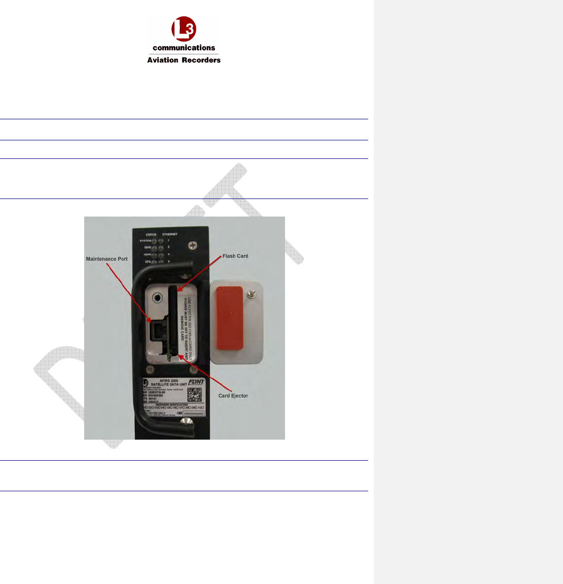
An RJ-45 Maintenance Port jack is located behind the access door on the front panel of the SDU.
Figure 7-1 – Maintenance Port Location
Note:
Upon initial configuration of an installed system, perform and complete the Before Power-On Tests
in Section 8.1, before applying power to the Iridium SATCOM System.
AFIRS 228S Iridium Global Communications System Installation Manual
16 July 2014 L-3 Aviation Recorders Proprietary Page 51
165E5733-00 Rev. 03
7.1 Access the Maintenance User Interface (MUI)
If an Electronic Flight Bag (EFB) with a supported web browser installed is connected to one
of the rear Ethernet port connections, the EFB can be used as an AFIRS maintenance terminal
and a laptop is not required.
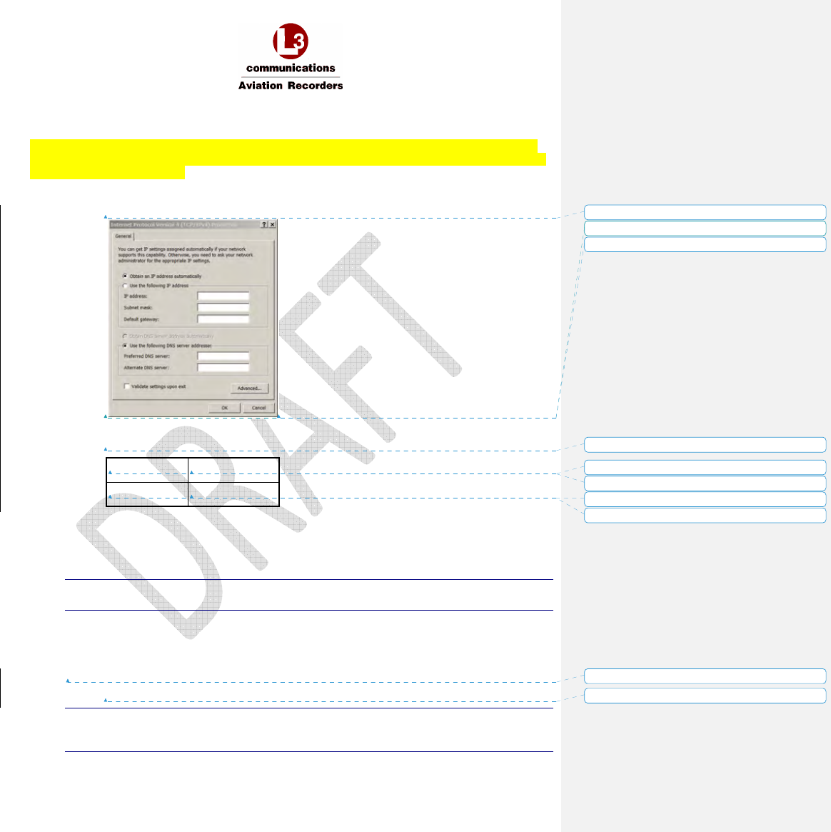
1. On the laptop computer set the IP address to one of the following:
a. Set the Internet Protocol to: Obtain an IP Address Automatically
OR
b. Use the following IP address:
IP address:
196.168.128.10
Subnet mask:
255.255.255.0
2. Connect an Ethernet cable to the Maintenance Port via the front panel access door of the SDU
- system power may be on or off.
3. Connect the other end of the Ethernet cable to a laptop with a web browser.
Note:
Mozilla Firefox ® is the recommended Internet browser with the SDU.
4. If not already powered, apply power to the SDU.
5. Confirm that there is either a steady, or flashing, green link light (adjacent to Maintenance Port
RJ45 connector). A flashing light indicates that data is being transmitted.
6. Open a web browser on the laptop. In the Address bar, type the following IP address:
192.168.128.1
Note:
Before opening the web page, clear the web browser’s cache, or Ctrl+F5 and re-open the web
page.
Formatted: No underline, Font color: Auto
Formatted: No underline, Font color: Auto
Formatted: No underline, Font color: Auto
Formatted: No underline, Font color: Auto
Formatted: No underline, Font color: Auto
Formatted: No underline, Font color: Auto
Formatted: No underline, Font color: Auto
Formatted: No underline, Font color: Auto
Formatted: No underline, Font color: Auto
Formatted: No underline, Font color: Auto
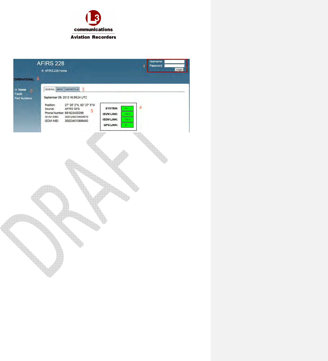
AFIRS 228S Iridium Global Communications System Installation Manual
16 July 2014 L-3 Aviation Recorders Proprietary Page 52
165E5733-00 Rev. 03
The Iridium SATCOM System home page appears with the General tab information displayed.
Figure 7-2 – Home Page – General Tab
1 Login area
2 Menu of available links to pages accessible to various users upon login
3 Tabs: General, ARINC, and Discrete In
4 System and Link status display area
5 System information data display area
6 Mode: OPERATIONAL, MAINTENANCE, INITIALIZING, etc.
7.1.1 Home Page Tab Descriptions
No user name or password is required to open the MUI home page.
General Tab
• UTC Date and Time: This is correlated to a GPS clock if the ICT parameter “Internal GPS =
Active”. If no link is available (i.e. during startup), a default date is displayed.
• Position: This is the AFIRS GPS position. If no GPS is fixed, no GPS will be displayed.
• Phone Number: Displays the aircraft phone number (12 digits).
*Important: The phone number displayed may not be correct - check the SIM card.
• ISVM IMEI: Iridium Satellite Voice Modem International Mobile Equipment Identity (15 digits).
• ISDM IMEI: Iridium Satellite Data Modem International Mobile Equipment Identity (15 digits).
AFIRS 228S Iridium Global Communications System Installation Manual
16 July 2014 L-3 Aviation Recorders Proprietary Page 53
165E5733-00 Rev. 03
• Iridium SATCOM System Status Indicators
System
Yellow = (INIT) initializing Green = OK
Yellow = FAULT Yellow (blank) = system is in Maintenance Mode
Red = SDU Configuration Module (SCM) or Satellite Data Unit (SDU) Hardware failure
or other critical error.
ISVM and ISDM LINK
Yellow = NO LINK, no Iridium link if CSQ (Channel Signal Quality) is 0-1
Green = OK, if CSQ is 2-5
GPS LINK
Yellow = NO FIX
Green = OK
ARINC Tab
• Displays the status of the 16 ARINC 429 RX channels.
• The status of a configured function is either ACTIVE (green) or FAULT (red).
• The ARINC 717 RX configuration is currently not used.
Discrete In Tab
• Displays the state of the 16 Discrete Inputs.
• The state of the configured functional input is either ACTIVE (green) or INACTIVE (blue).
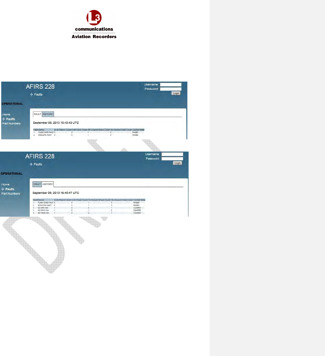
AFIRS 228S Iridium Global Communications System Installation Manual
16 July 2014 L-3 Aviation Recorders Proprietary Page 54
165E5733-00 Rev. 03
7.1.2 Faults Page
The Faults page provides access to the system fault log and fault history.
• FAULT tab displays only currently-raised faults
• HISTORY tab displays all raised and cleared faults since the last system reboot
Figure 7-3 – Faults Page (Fault Tab)
Figure 7-4 – Faults Page (History Tab)
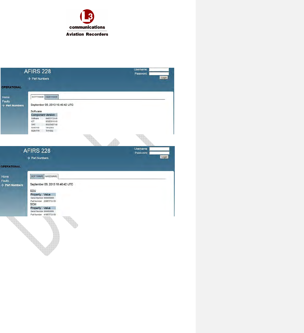
AFIRS 228S Iridium Global Communications System Installation Manual
16 July 2014 L-3 Aviation Recorders Proprietary Page 55
165E5733-00 Rev. 03
7.1.3 Part Numbers Page
The Part Numbers page provides the software and hardware configuration status of the Iridium
SATCOM System.
Figure 7-5 – Part Numbers Page (Software Tab)
Figure 7-6 – Part Numbers Page (Hardware Tab)
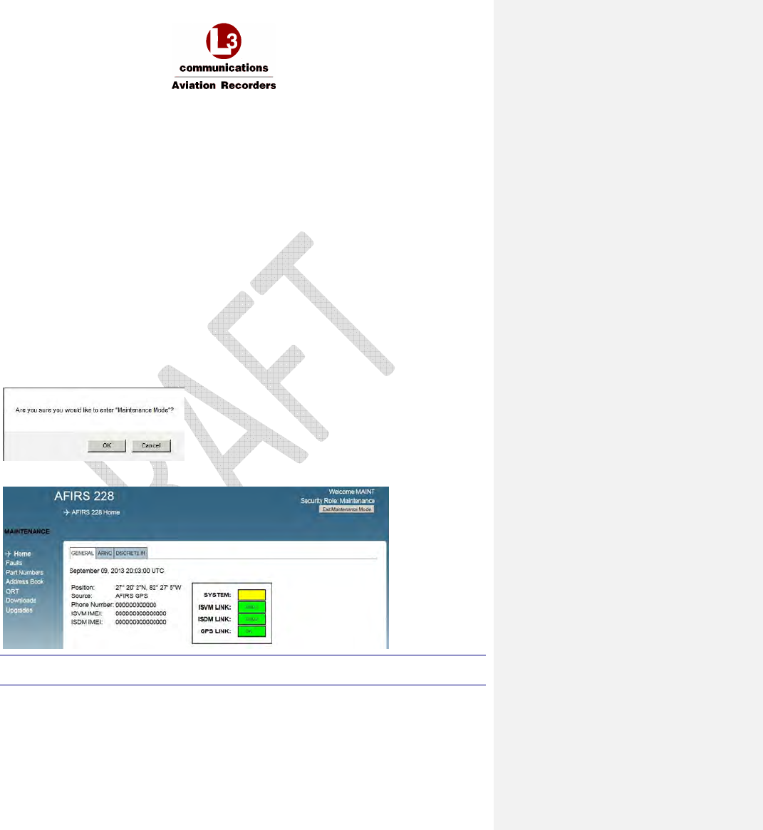
AFIRS 228S Iridium Global Communications System Installation Manual
16 July 2014 L-3 Aviation Recorders Proprietary Page 56
165E5733-00 Rev. 03
7.2 Maintenance Mode
To enter Maintenance Mode, the aircraft must be deemed “On-Ground.” If the aircraft is deemed “In-
Air”, the [Enter Maintenance Mode] button will be, or will become, unavailable.
If the aircraft status changes to “In-Air” while in Maintenance Mode, the system will reboot
automatically and return to Operational Mode.
The following users can enter Maintenance Mode after log in:
Maintenance User (View Upgrades page, modify 5 parameters on the ORT page)
Administrator User (View Upgrades page, modify parameters on the UAT page)
Role-based MUI permissions are provided in Table 7-1 through Table 7-3 at the end of this section.
Enter Maintenance Mode
1. Once connected to the Iridium SATCOM System MUI, on the Home page, enter your user
name and password and click Login.
2. If the aircraft is deemed “On-Ground”, the [Enter Maintenance Mode] button is available at the
top right corner of the screen.
3. Click Enter Maintenance Mode.
The following message displays, prompting for confirmation to enter Maintenance Mode.
4. Click OK.
The Home screen displays. The SYSTEM status indicates Yellow (blank).
Note:
Entering Maintenance Mode disables all MCDU functions.
Figure 7-7 – Maintenance Mode Initial Display Screen
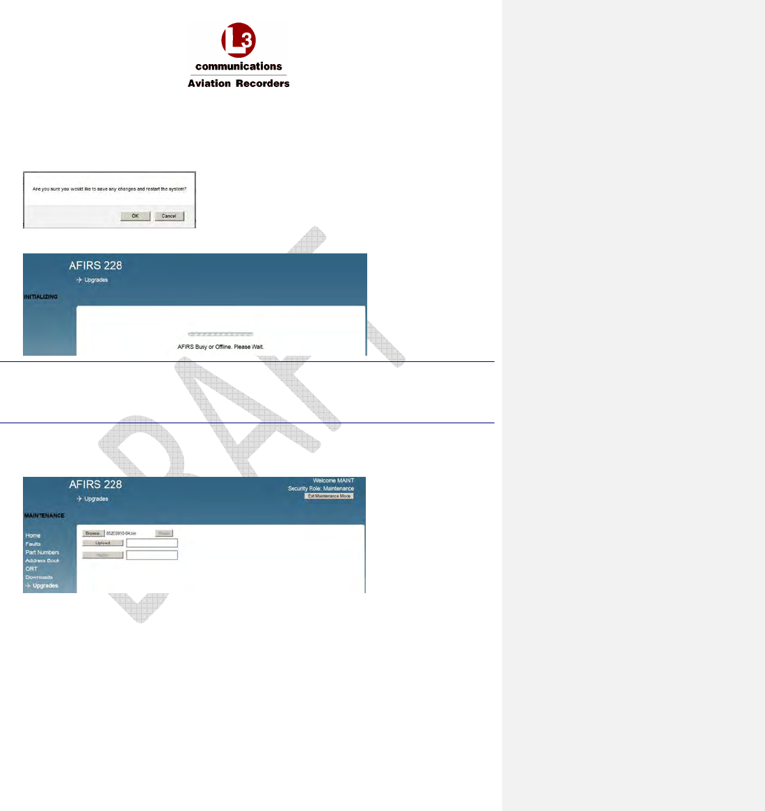
AFIRS 228S Iridium Global Communications System Installation Manual
16 July 2014 L-3 Aviation Recorders Proprietary Page 57
165E5733-00 Rev. 03
Exit Maintenance Mode
1. Upon completion of uploading of data or software files or modifying parameters, click Exit
Maintenance Mode for the changes to take effect.
The following dialog box will display, prompting for confirmation to save changes.
2. Click OK, then the system will restart.
The following screen will display.
Note:
Exiting Maintenance Mode enables all MCDU functions.
If the aircraft status changes to “In-Air” while in Maintenance Mode, the system will reboot
automatically and return to Operational Mode, disregarding incomplete file uploads.
7.2.1 Maintenance Mode Upgrades Page
1. Click Upgrades from the Maintenance menu to upload software or data files.
The following page will display.
2. Click Browse to navigate and select the software or data file to be uploaded.

AFIRS 228S Iridium Global Communications System Installation Manual
16 July 2014 L-3 Aviation Recorders Proprietary Page 58
165E5733-00 Rev. 03
3. Click Upload.
Success
• The blue progress bars turn green.
• The uploaded data files display a CRC code.
• The uploaded software file displays the part number of the software.
Incomplete
• Non-compatible files will be rejected and an error message will display.
4. Click Apply to start the verification process.
Success
• The blue progress bars turn green.
Incomplete
• Non-compatible files will be rejected and an error message will display.
5. Click Reset in to upload another file.
6. Click Exit Maintenance Mode. The system must re-boot for changes to take effect.
Note:
If the aircraft’s status changes to “In-Air” before uploading is complete, the system will reboot
automatically and return to Operational Mode - disregarding incomplete uploads.
7. Maintenance User can modify only 5 ORT parameters:
a. Click ORT (Owner Requirements Table) to configure customized settings for specific
aircraft and or operator requirements.
8. Administrator User can modify any UAT parameter:
a. Click UAT (User Access Table) to configure user access privileges.
9. Click Exit Maintenance Mode. The system reboots and returns to Operational Mode.
Note:
If the aircraft’s status changes to “In-Air” before uploading is complete, the system will reboot
automatically and return to Operational Mode - disregarding incomplete uploads.

AFIRS 228S Iridium Global Communications System Installation Manual
16 July 2014 L-3 Aviation Recorders Proprietary Page 59
165E5733-00 Rev. 03
THIS PAGE INTENTIONALLY LEFT BLANK
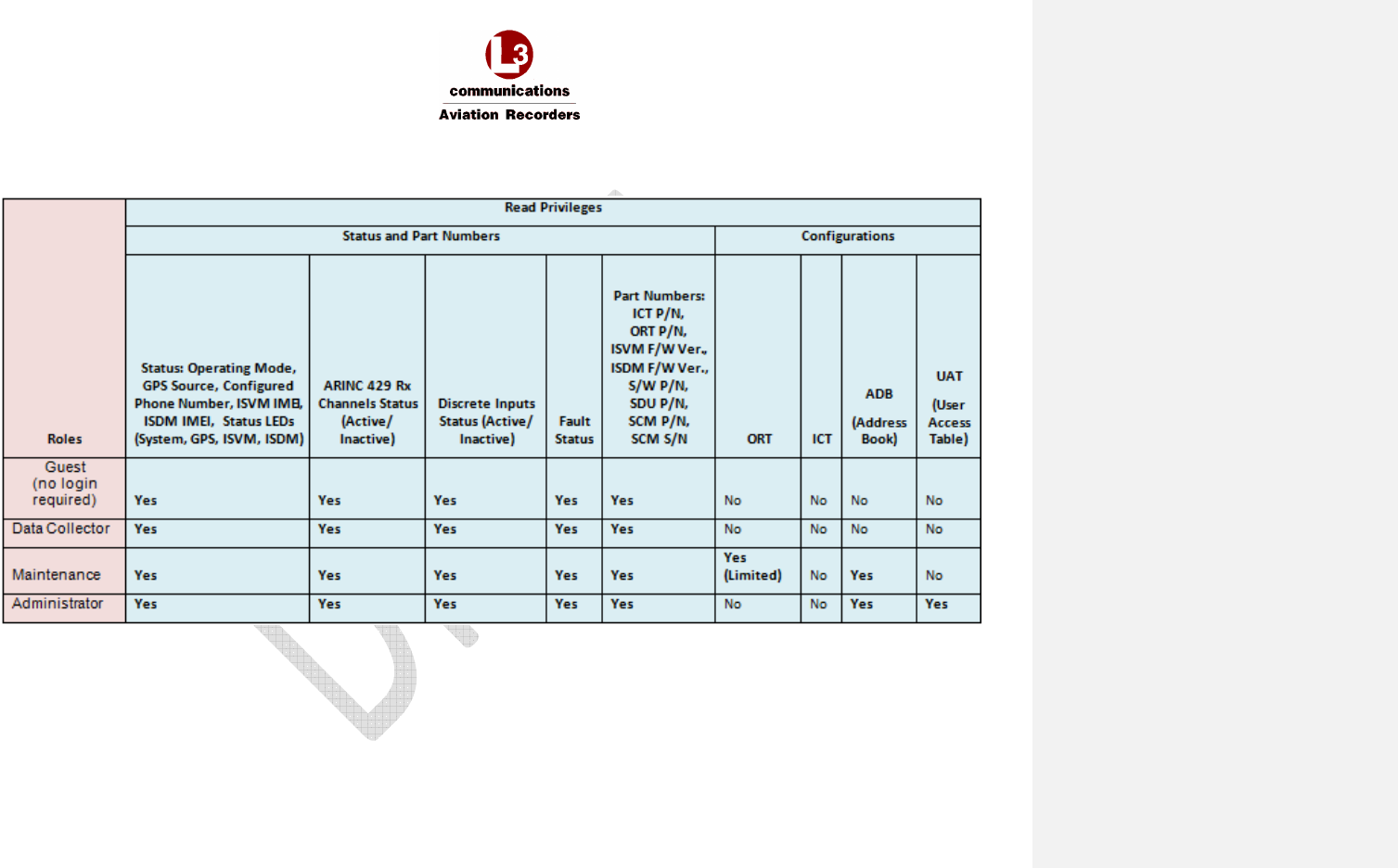
AFIRS 228S Iridium Global Communications System Installation Manual
16 July 2014 L-3 Aviation Recorders Proprietary Page 60
165E5733-00 Rev. 03
Table 7-1 - Read Privileges by Role
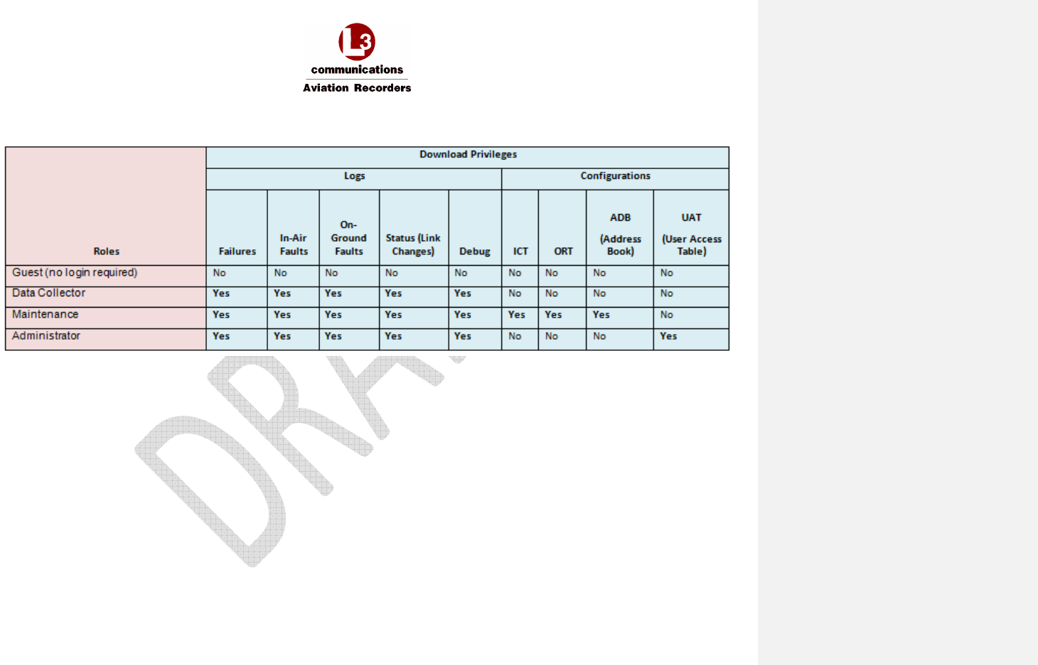
AFIRS 228S Iridium Global Communications System Installation Manual
16 July 2014 L-3 Aviation Recorders Proprietary Page 61
165E5733-00 Rev. 03
Table 7-2 - Download Privileges by Role
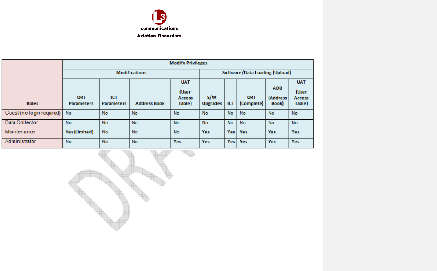
AFIRS 228S Iridium Global Communications System Installation Manual
16 July 2014 L-3 Aviation Recorders Proprietary Page 62
165E5733-00 Rev. 03
Table 7-3 – Modify Privileges by Role

AFIRS 228S Iridium Global Communications System Installation Manual
16 July 2014 L-3 Aviation Recorders Proprietary Page 63
165E5733-00 Rev. 03
THIS PAGE INTENTIONALLY LEFT BLANK

AFIRS 228S Iridium Global Communications System Installation Manual
16 July 2014 L-3 Aviation Recorders Proprietary Page 64
165E5733-00 Rev. 03
7.3 Configure the Iridium SATCOM System
The following sections are intended to provide information on the configuration process and data
inputs required to install and verify a system as operational. For the purposes of installation, system
configuration, and verification, the following steps should be completed:
1. Address Book to upload
2. ORT parameters for Maintenance User
3. ICT file to upload
4. UAT parameters for user roles
Reminder:
To enter Maintenance Mode, the aircraft must be deemed “On-Ground”.
The following users can enter Maintenance Mode after log in:
Maintenance User – 5 ORT parameters
Administrator User – UAT parameters
7.3.1 Address Book
• Can be uploaded as a comma-separated-values file (adb.csv).
• Can contain up to 300 Address Book entries.
• Can be viewed by Maintenance and Administrator users after login in Operational mode.
• Entries can be modified, if unprotected, via the MCDU in Operational mode.
• Can be downloaded as ‘adb.csv’ file in the MUI (including modifications that have been made
via the MCDU) by the Maintenance User after login in Operational Mode
The following restrictions and limitations apply to the parameters of a compatible adb.csv file:
• Phone Number – up to 18 digits
• Name – up to 23 upper-case alpha-numeric characters; A-Z, 0-9, +, -, /, space
• Priority – 4 (Public), 3 (Non-Safety), 2 (Safety), 1 (Emergency)
• Protected – 0 (No) = Entry can be modified or deleted via the MCDU in Operational Mode.,
1 (Yes) = Entry cannot be modified via the MCDU in Operation Mode.
• Directory - 4 (Public), 3 (Non-Safety), 2 (Safety), 1 (Emergency)
• Speed Dial 1 – 1 (address book appears in the cockpit for pilot’s use)
• Speed Dial 2 – 0 (currently not used)
• Speed Dial 3 – 0 (currently not used)
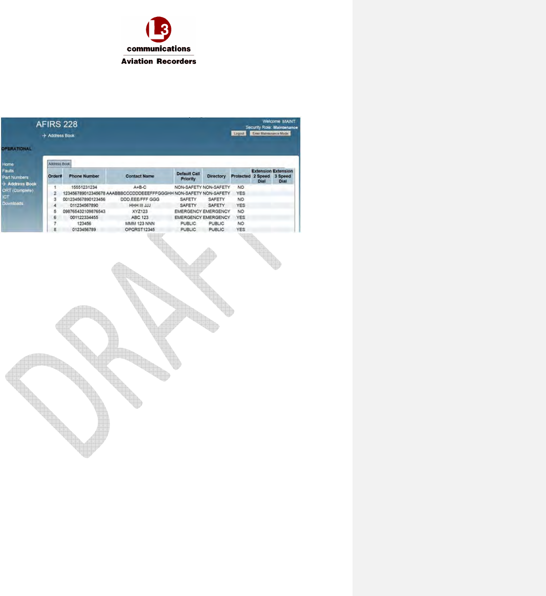
AFIRS 228S Iridium Global Communications System Installation Manual
16 July 2014 L-3 Aviation Recorders Proprietary Page 65
165E5733-00 Rev. 03
View the Address Book in the MUI
1. In Operational Mode, log in as Maintenance User or Administrator User.
2. Click Address Book. The Address Book will display.
3. Address Book entry fields:
• Order#: Up to 300 address book entries
Note: This parameter is not part of the adb.csv file.
• Phone Number: From 6 to 18 digits
• Contact Name: Up to 23 upper-case alpha-numeric characters
• Default Call Priority and Directory: Options displayed are Emergency, Safety, Non-
Safety, and Public.
• Protected:
YES = Entry cannot be modified via the MCDU in Operational Mode
NO = Entry can be modified or deleted via the MCDU in Operational Mode
• Extension 2 and 3 Speed Dial: Currently not used.
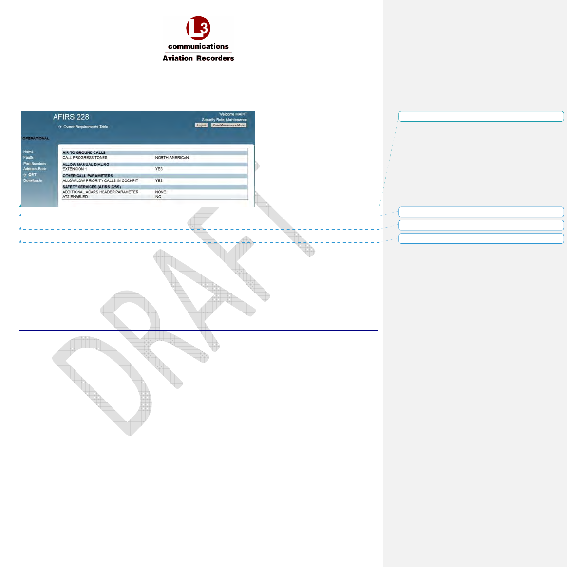
AFIRS 228S Iridium Global Communications System Installation Manual
16 July 2014 L-3 Aviation Recorders Proprietary Page 66
165E5733-00 Rev. 03
7.3.2 Owner Requirements Table (ORT) Parameters
The Owner Requirements Table (ORT) contains the parameters that may be customized by the
individual aircraft operator.
These settings may be changed as required to meet operational requirements or preferences.
The ORT file can be uploaded and downloaded as a binary file by the Maintenance User.
Modification of the ORT will cause the MOD label to display on the MCDU under the ORT P/N.
The file name of an up-loadable ORT file has a part number; for example, “852E5927-00.bin”. It is
version-controlled and the CRC is calculated and displayed during the upload process for verification.
If the ORT has been modified, the text “MOD” will be displayed on the MCDU, under the ORT Part
Number.
The default file name of a downloaded ORT file is “ort.bin”.
Note:
An ORT Configuration Worksheet is provided in Appendix B to assist the operator in selecting and
documenting the correct ORT configuration settings.
Formatted: No underline, Font color: Auto
Formatted: No underline, Font color: Auto
Formatted: No underline, Font color: Auto
Formatted: No underline, Font color: Auto
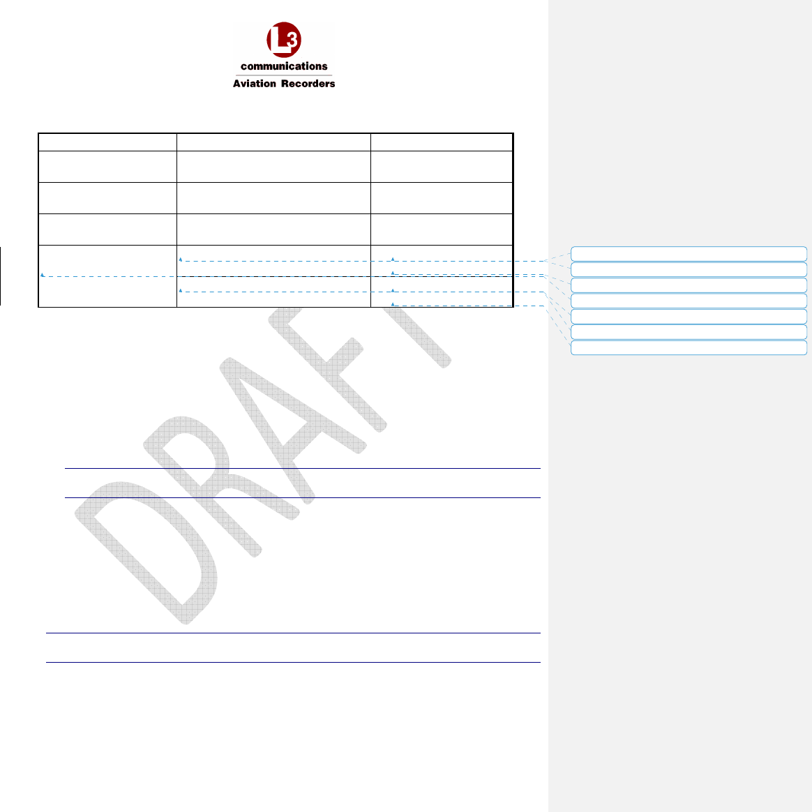
AFIRS 228S Iridium Global Communications System Installation Manual
16 July 2014 L-3 Aviation Recorders Proprietary Page 67
165E5733-00 Rev. 03
Access and Modify ORT Parameters
ORT Group
ORT Parameter Name
Value
Air
to Ground Calls
Call Progress Tones
NORTH AMERICAN
EUROPEAN
Allow Manual Dialing Extension 1 YES
NO
Other Call Parameters
Allow Low Priority Calls in Cockpit
YES
NO
Safety Services (Iridium
SATCOM System)
Additional ACARS Header Parameter
NONE
ARINC
ATS Enabled YES
NO
1. Log in with user name and password as Maintenance User while aircraft is “On-Ground”.
2. Click Enter Maintenance Mode.
3. Click the ORT link on the left side of the screen to open the ORT page.
4. AIR TO GROUND CALLS - CALL PROGRESS TONES:
The call progress tones can be configured to either North American (default) or European.
5. ALLOW MANUAL DIALING - EXTENSION 1:
YES = Manually-dialed phone calls can be placed from the cockpit, and via the directory.
NO = Phone calls from the cockpit can be placed only by using the directory
Note:
If set to NO, the MANUAL DIAL prompt will not be available on the MCDU.
IMPORTANT! For operational approval for safety-services voice in accordance with FAA
AC20-150A, Extension 1 must be configured YES to allow manual dialing for the flight crew.
6. OTHER CALL PARAMETERS – ALLOW LOW PRIORITY CALLS IN COCKPIT:
Low-priority calls are considered PUBLIC or Priority 4.
YES = Low-priority calls can be received in the cockpit, and low-priority calls can be placed
from the cockpit.
NO = Low-priority incoming calls will not ring in the cockpit, and no low-priority calls can be
placed from the cockpit.
Note:
If set to NO, the PUBLIC directory prompt will not be available on the MCDU.
Formatted: No underline
Formatted: No underline
Formatted: No underline
Formatted: No underline
Formatted: No underline
Formatted: No underline
Formatted: No underline
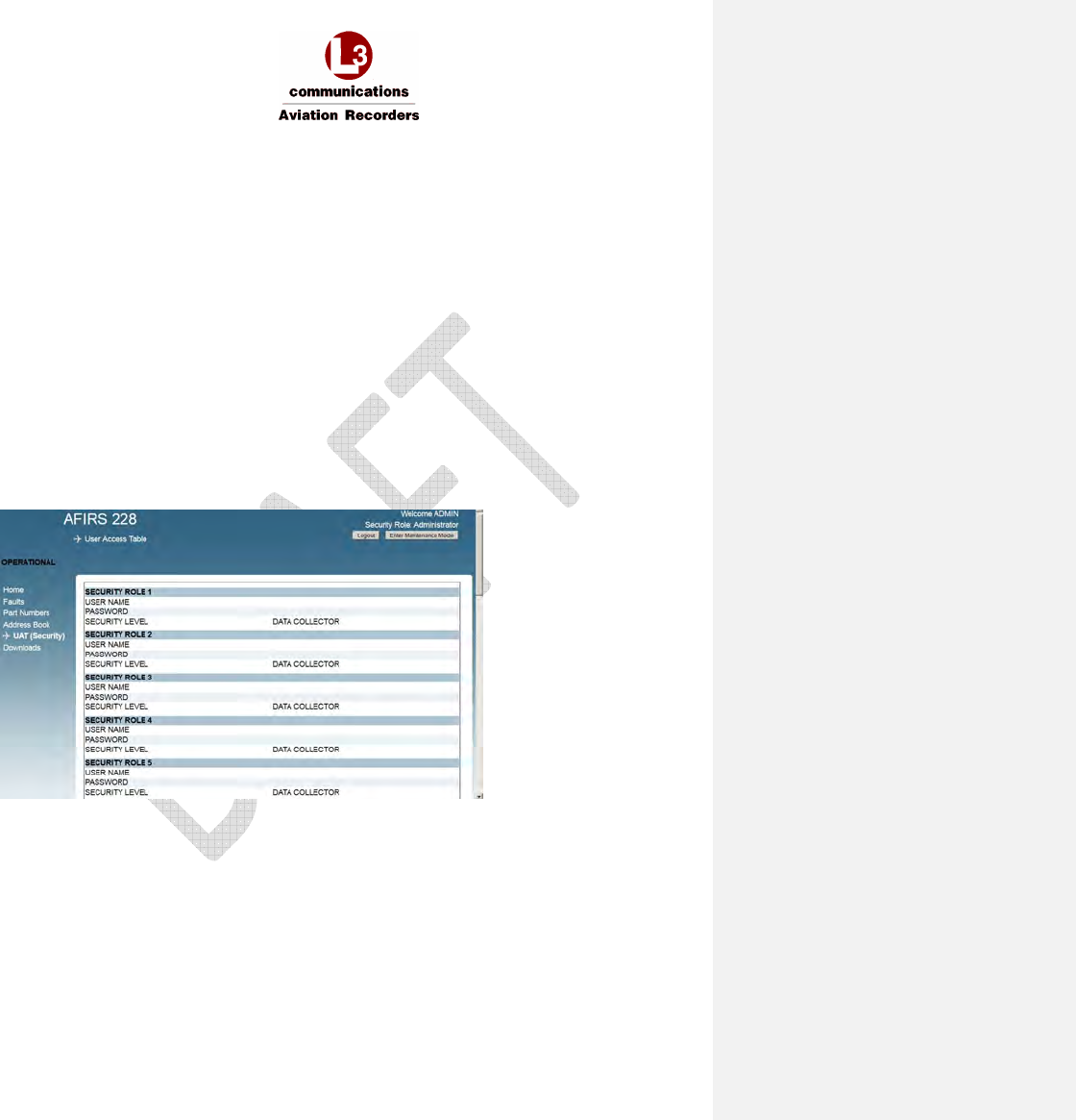
AFIRS 228S Iridium Global Communications System Installation Manual
16 July 2014 L-3 Aviation Recorders Proprietary Page 68
165E5733-00 Rev. 03
7. SAFETY SERVICES (Iridium SATCOM System) – ADDITIONAL ACARS HEADER
PARAMETER: The default configuration of NONE corresponds to SITA; alternatively, select
ARINC.
8. ATS ENABLED:
YES = Safety / ATS (Air Traffic Service) SIM card installed in the SCM.
NO = Non-Safety / NON-ATS (Air Traffic Service) SIM card installed in the SCM.
7.3.3 Installation Configuration Table (ICT)
The Installation Configuration Table (ICT) parameters may not be viewed or modified.
The ICT file can be uploaded and downloaded as a binary file by the Maintenance User.
The file name of an uploadable ICT file has a part number; for example, “852E5910-00.bin”. It is
version-controlled and the CRC is calculated and displayed during the upload process for verification.
The default file name of a downloaded ICT file is “ict.bin”.
7.3.4 User Access Table (UAT) Parameters
The User Access Table (UAT) is used by an Administrator User to set up user access privileges for up
to 20 users. These settings may be changed as required to meet operational requirements.
Access and Modify UAT Parameters
1. Log in with user name and password as Administrator User while the aircraft is “On-Ground”.
2. Click Enter Maintenance Mode.
3. Click the UAT (Security) link on the left side of the screen to open the UAT page.
4. USER NAME: From 4 to 20 upper-case alphanumeric characters
5. PASSWORD: From 4 to 20 upper-case alphanumeric characters
6. SECURITY LEVEL: Select either DATA COLLECTOR (default) or MAINTENANCE or
ADMINISTRATOR.

AFIRS 228S Iridium Global Communications System Installation Manual
16 July 2014 L-3 Aviation Recorders Proprietary Page 69
165E5733-00 Rev. 03
Exit Maintenance Mode
Upon completion of modifying parameters, click Exit Maintenance Mode for the system to reboot and
the changes to take effect.
Note:
Exiting Maintenance Mode enables all MCDU functions.
If the aircraft status changes to “In-Air” while in Maintenance Mode, the system will reboot
automatically and return to Operational Mode.
7.4 Upgrade Iridium SATCOM System Software
The Iridium SATCOM System software may be upgraded in the field using the Upgrade function of
the MUI in Maintenance Mode.
Maintenance and Administrator Users have privileges to login and upload software and data files
while aircraft status is “On-Ground”.
7.4.1 Upgrade Materials
Make sure to have the following materials available before beginning the upgrade procedure.
• A notebook computer with an Ethernet port, running the Microsoft Windows operating system
and a web browser such as Mozilla Firefox ® (see Section 7.1 Access the Maintenance User
Interface).
• A standard, straight-through Ethernet patch cable.
• The software release folder that contains the upgrade file (upgrade.tgz).
• The software release notes to identify any changes to functionality or special upload
instructions.
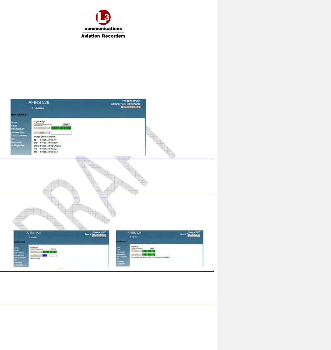
AFIRS 228S Iridium Global Communications System Installation Manual
16 July 2014 L-3 Aviation Recorders Proprietary Page 70
165E5733-00 Rev. 03
7.4.2 Upgrade the Iridium SATCOM System Software
1. From the left menu, click Upgrades. The Upgrades screen will display.
2. Click Browse to locate the software file to upload (upgrade.tgz).
3. Select the software file and click Upload.
Blue progress bars indicate the file uploading status. When the upload is complete and
successful, the progress bars turn green, and the new Software Part Numbers of the new
software image will be displayed.
Note:
Incompatible files will be rejected. The progress bars will turn red, and an error message will
display next to the progress bars. Click Reset to restart the upgrade process.
If you uploaded an incorrect file, but have not yet clicked Apply, click Reset to restart the upgrade
process
.
4. Click Apply to verify and load the software into non-volatile memory.
Blue progress bars indicate the status of the software file being installed on the SDU. When
the software verification has successfully completed, the progress bars turn green, and a
message displays that the system must be restarted for the changes to take effect.
Note:
If the aircraft status changes to “In-Air” at any time during the upgrade process, the system will
reboot automatically and return to Operational Mode, disregarding incomplete upgrades.
To activate the newly installed software, you must Exit Maintenance Mode and restart the SDU.
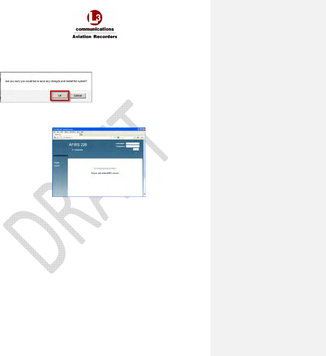
AFIRS 228S Iridium Global Communications System Installation Manual
16 July 2014 L-3 Aviation Recorders Proprietary Page 71
165E5733-00 Rev. 03
5. Click Exit Maintenance Mode at the top-right corner of the MUI screen.
A confirmation message displays prompting to confirm that you want to exit Maintenance
Mode.
6. Click OK.
The SDU automatically restarts and applies the newly-installed software. A message
displays indicating that the AFIRS system is rebooting.
7. When the restart is complete, verify that the SDU is in Operational Mode and functioning
as expected. To verify that the correct software version and configurations have been
loaded, check the following:
a. From the Home page, click on the General, ARINC, and Discrete In tabs to review the
system and link status, and the status of the ARINC 429 Rx and Discrete In
connections.
b. Click on the Faults page to verify any faults that might be raised.
c. Click on the Part Numbers page to verify that the software part number displayed
matches the software version and part number as noted in the release notes or
upgrade instructions.
d. Enter User Name and Password (Maintenance User) and click Login.
e. Maintenance User - Click ORT and review the ORT configurations to confirm that they
are correct.
f. Click Logout after your review is complete and satisfactory.
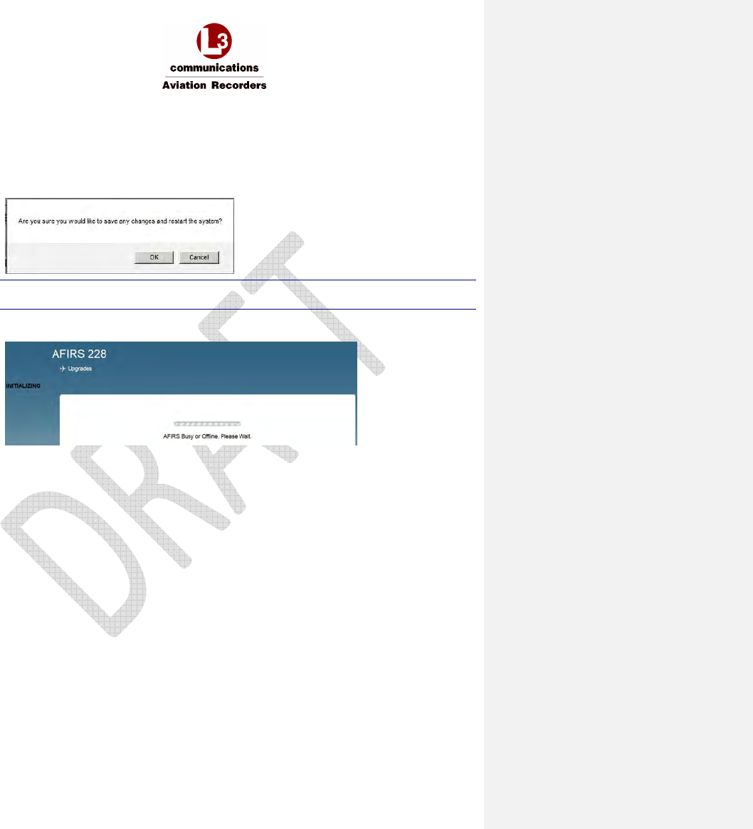
AFIRS 228S Iridium Global Communications System Installation Manual
16 July 2014 L-3 Aviation Recorders Proprietary Page 72
165E5733-00 Rev. 03
7.5 Exit Maintenance Mode
1. To save changes and uploaded configuration data, exit maintenance mode for the changes
to take effect
1. In the top-right corner of the screen, click Exit Maintenance Mode.
2. A Message displays prompting for confirmation to exit Maintenance Mode
Note:
If you click Cancel, changes are still active but not saved.
3. Click OK to exit Maintenance Mode, save your changes, and reboot the system.
The following message displays.
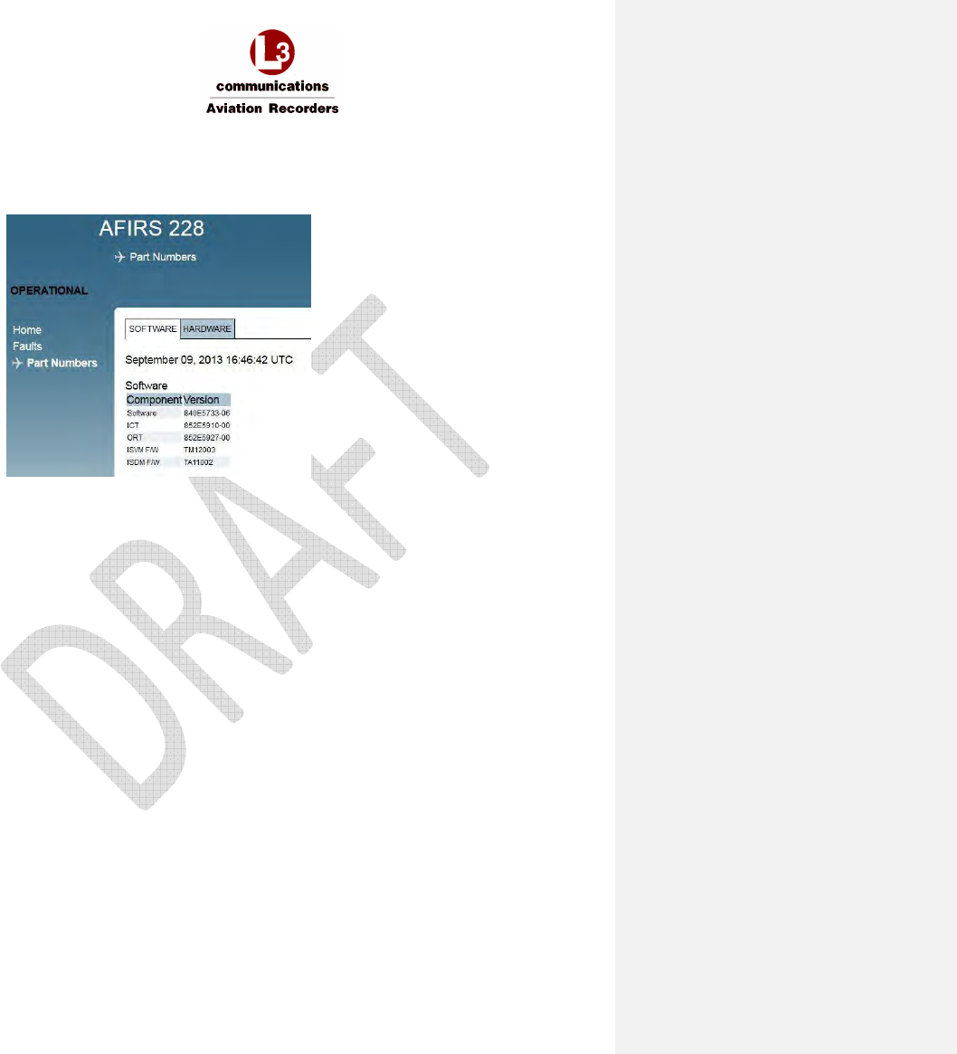
AFIRS 228S Iridium Global Communications System Installation Manual
16 July 2014 L-3 Aviation Recorders Proprietary Page 73
165E5733-00 Rev. 03
4. Once the system reboots to Operational Mode, verify your changes and confirm that the
correct software and data files have been installed.
5. Click the Part Numbers page and review the Software tab for the correct Part Numbers.
The Part Numbers screen displays.

AFIRS 228S Iridium Global Communications System Installation Manual
16 July 2014 L-3 Aviation Recorders Proprietary Page 74
165E5733-00 Rev. 03
8. MAINTENANCE AND CHECKOUT
This section provides instructions on post-installation checkout procedures and information on
Instructions for Continued Airworthiness.
8.1 Post-Installation Checkout
8.1.1 Before Power-On Tests
1. Before installing the SDU in the mounting tray, confirm that all aircraft interface wiring is
correct as per the aircraft wiring integration design.
2. Confirm that a valid SIM card is installed in the SDU Configuration Module (SCM).
3. Set the system circuit breaker for the Main power source and confirm that 28 VDC power is
available between pins J1C-2 and J1C-3. Pull the circuit breaker and ensure that Main power
is removed.
4. Place the SDU in the mounting tray and secure the front hold-down.
5. Open the front panel door and confirm that a flash card is installed in the SDU.
Note:
If no flash card is present, a FLASH CARD FAULT is generated in the MUI, and an SDU FAIL
will display on the MCDU SATCOM BITE STATUS page.
Only FLYHT P/N 502-1180-x flash cards should be used in the Iridium SATCOM System.
6. If installed, the cockpit FAULT indication should be illuminated when power is not applied to
the system.
7. Set the system circuit breaker for the Main power source. The SYSTEM LED indicator on the
front panel of the SDU will be yellow, indicating that the system is initializing.
Note:
The first time an SDU is installed in an aircraft, the SYSTEM LED indicator will typically remain
yellow even after it has initialized. The MUI will display an SCM Configuration Fault indicating
that the proper configuration settings have not yet been made.
8. Connect an Ethernet cable to the Maintenance Port in the front panel and follow procedures to
open the Maintenance User Interface (MUI) as described in Section 7.
9. Log in to the MUI as Maintenance User and Enter Maintenance Mode to install ICT and ORT
files in accordance with the procedures contained in Section 7. Exit Maintenance Mode to
reboot the system. Keep the laptop connected to the Maintenance Port after finishing the
configuration procedure.
10. Once the system resets, the SYSTEM LED indicator on the front panel of the SDU will turn
green once the system is operational.
11. The cockpit FAULT annunciator should remain illuminated whenever the SYSTEM STATUS
indicator is amber, and extinguish when the SYSTEM LED indicator turns green.
8.1.2 Aircraft Systems Interface Tests
Note:
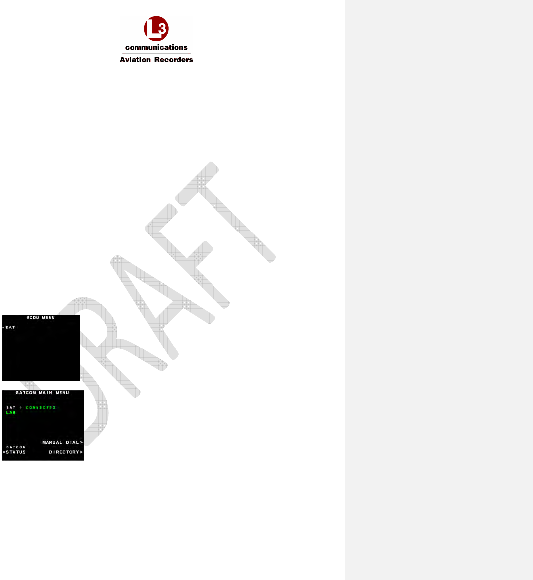
AFIRS 228S Iridium Global Communications System Installation Manual
16 July 2014 L-3 Aviation Recorders Proprietary Page 75
165E5733-00 Rev. 03
The tests listed in this section are generic in nature and are not intended to be used as a test
plan for any specific aircraft installation. They should only be used by the aircraft systems
integrator as a guide in developing the correct and complete aircraft-specific integration tests.
The aircraft systems integrator’s test plan should ensure that the aircraft and its systems are in
a safe condition for each test to be performed.
8.1.2.1 Main Power Test
1. Confirm that 28 VDC power is available at the Main power input, and that the Iridium SATCOM
System is initialized and operating.
2. Using the MUI Home page General tab, confirm that the System status and Datalinks are
green.
8.1.2.2 ARINC 429 Databus Interface Tests
1. On the MUI, click on the ARINC tab on the Home page.
2. Confirm the aircraft systems connected to the databus ports being tested are operational and
transmitting on the databus.
3. Confirm that the ARINC 429 Rx (1-16) channels used are shown as ACTIVE.
8.1.2.3 MCDU Tests
Confirm SATCOM functionality on each MCDU as follows:
1. On the MCDU MENU page, the <SAT prompt should be available at one of the Line Select
Keys (LSKs). Press the LSK to display the SATCOM MAIN MENU page.
2. On the SATCOM MAIN MENU, press the LSK for the SATCOM STATUS page.
The SATCOM STATUS page should be displayed with log-on state as well as voice and
datalink status information.
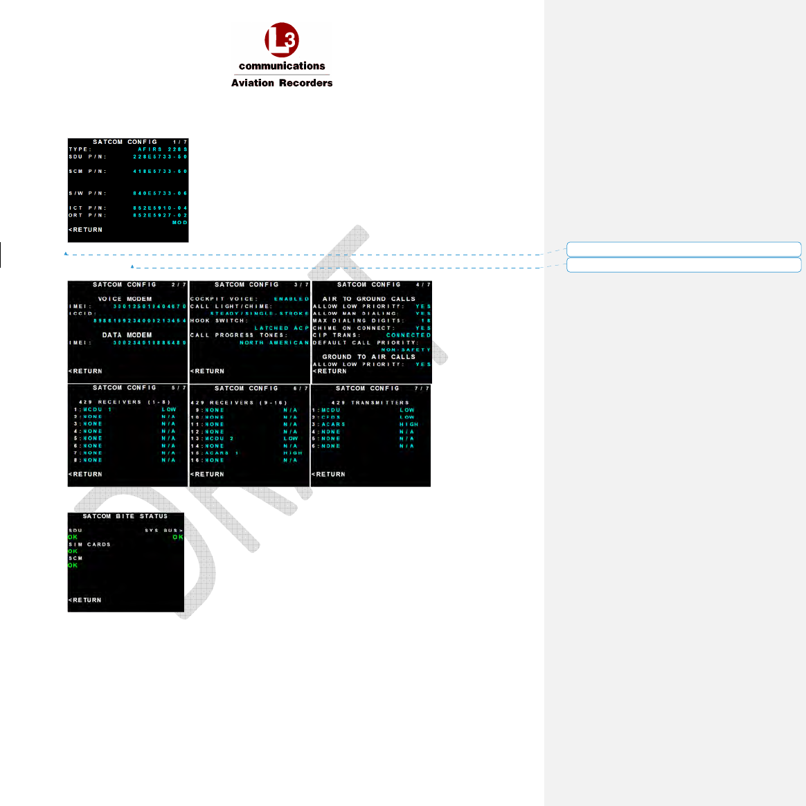
AFIRS 228S Iridium Global Communications System Installation Manual
16 July 2014 L-3 Aviation Recorders Proprietary Page 76
165E5733-00 Rev. 03
3. On the SATCOM STATUS page, press the LSK of the CONFIG prompt. The SATCOM
CONFIG page 1 of 7 should be displayed.
If the ORT has been modified, the text “MOD” will be displayed on the MCDU, under the ORT
Part Number.
4. Press Arrow Down or Arrow Up to view current configurations to page 7.
5. On the SATCOM STATUS page, press the LSK of the BITE prompt to display the SATCOM
BITE STATUS page to display the status of the SDU, SIM CARDS, and SCM.
Formatted: No underline, Font color: Auto
Formatted: Not Highlight
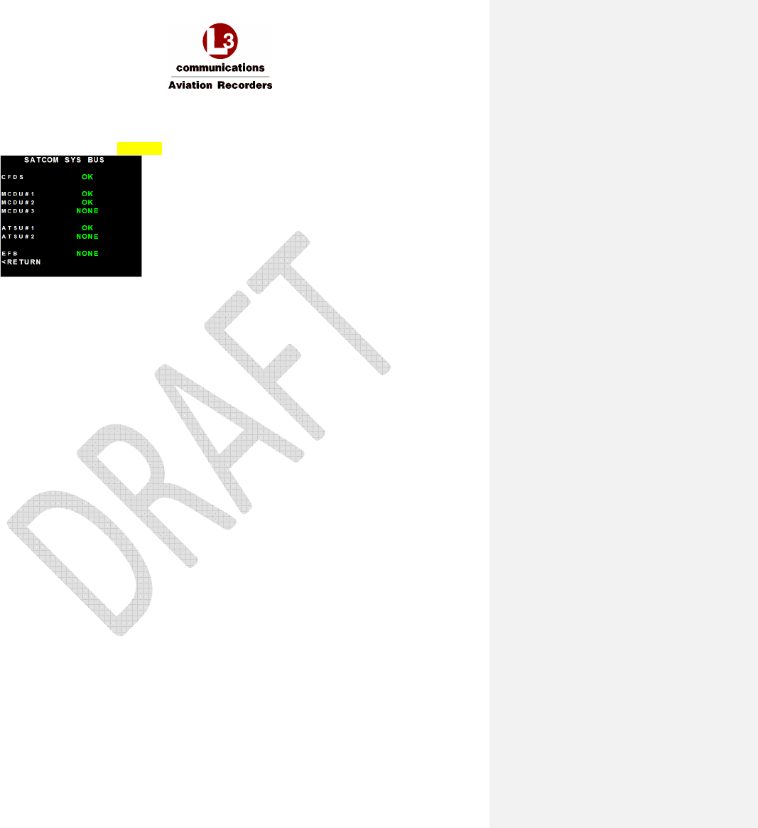
AFIRS 228S Iridium Global Communications System Installation Manual
16 July 2014 L-3 Aviation Recorders Proprietary Page 77
165E5733-00 Rev. 03
6. On the SATCOM BITE STATUS page, press the LSK of the SYS BUS prompt. The SATCOM
SYS BUS page should display with status information of the MCDU#1, MCDU#2, MCDU#3,
ATSU#1, and ATSU#2 and EFB.
7. Press the <RETURN LSK several times to return to the SATCOM MAIN MENU page.
8.1.2.4 Ethernet Port Tests
1. Confirm connectivity to each Ethernet device as follows:
2. Confirm that the SDU front panel ETHERNET LEDs for the connected ports are green.
Flashing green indicates data is being transferred.
3. Perform any tests specific to the connected system to confirm that it is communicating with the
SDU over the Ethernet port.
8.1.2.5 Discrete Input Tests
For each discrete input connected (1-16), confirm the correct aircraft system interface as follows:
1. Using the Maintenance User Interface (MUI), click on the Discrete In tab on the Home page.
2. Select the discrete input to its inactive state. Confirm proper operation of the interfaced aircraft
system.
3. Select the discrete input to its active state. Confirm proper operation of the interfaced aircraft
system.
8.1.2.6 Discrete Output Tests
For each discrete output configured and connected (1-8), confirm the correct state is detected as
follows:
1. Manipulate the system providing the discrete output as required to indicate the output active
state
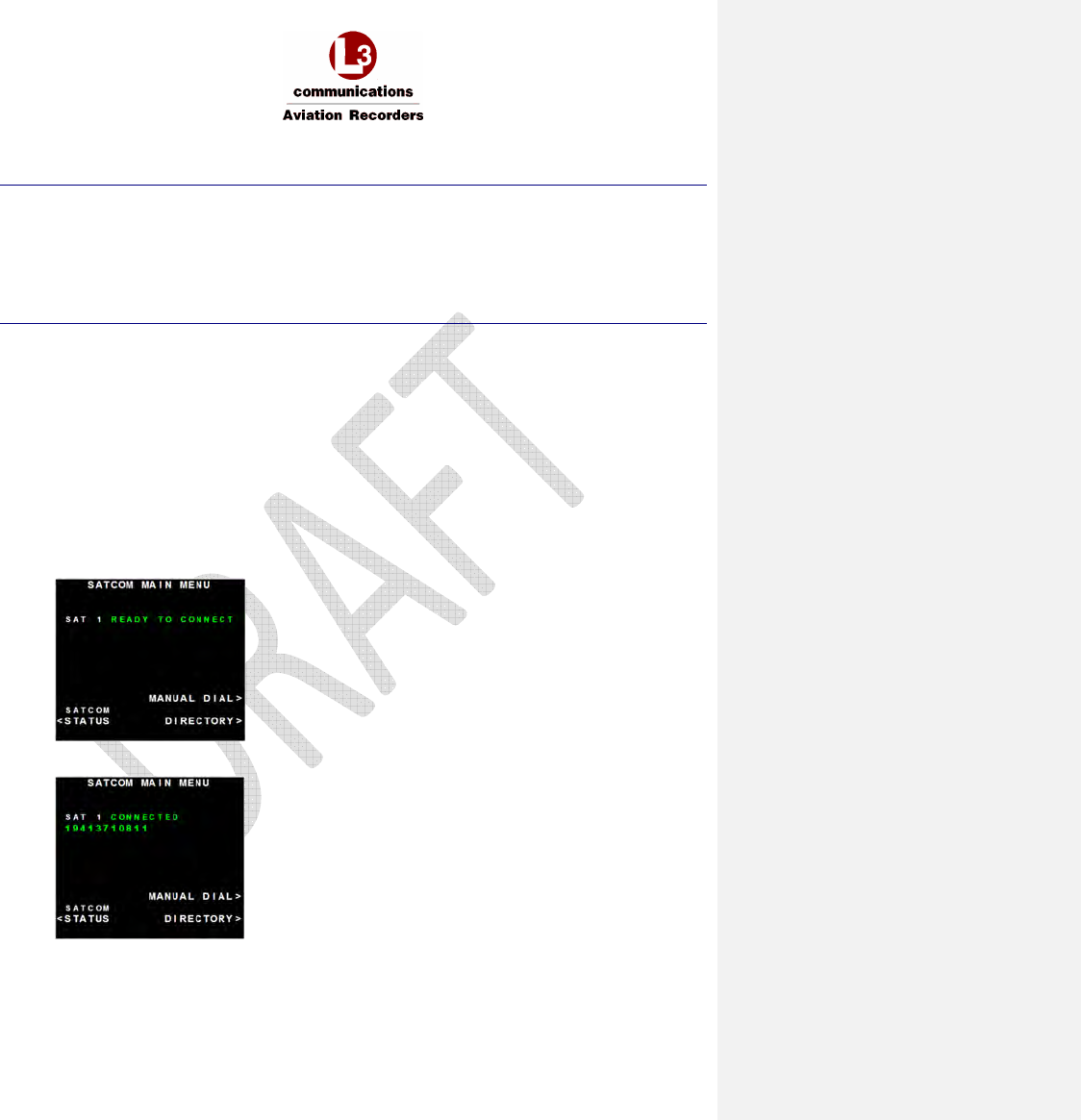
AFIRS 228S Iridium Global Communications System Installation Manual
16 July 2014 L-3 Aviation Recorders Proprietary Page 78
165E5733-00 Rev. 03
8.1.3 Operational System Tests
Note:
The tests in this section require the aircraft to be powered and outside the hangar in a location that
has a clear view of the Iridium and GPS satellites. Aircraft systems that interface with the Iridium
SATCOM System must be installed and operational.
These tests also require the AFIRS system to be activated on the Iridium network by SIM card
provider, and a valid SIM card installed in the SCM. Ensure that the ORT configuration ATS Enabled
(Yes/No) matches the SIM card type installed.
8.1.3.1 Date, Time, and Position Tests
1. Open the MUI to display the AFIRS Home page.
2. Confirm that the correct date, time, and position (UTC) information is displayed.
3. If the Internal GPS is configured as Active, the MUI display is showing AFIRS GPS and the
GPS Link is displayed green.
8.1.3.2 Datalink Tests
1. Confirm on the MUI that the ISVM and ISDM Links are green, and the MCDU SATCOM
STATUS page displays LOGGED-ON.
8.1.3.3 SATCOM Voice Tests
1. Confirm that the MCDU SATCOM MAIN MENU page displays Ready to Connect.
2. Place an air-to-ground call by using the MCDU. Confirm proper MCDU indications for a call in
progress.
3. Terminate the call from the cockpit. Confirm proper cockpit indications and return to Ready to
Connect state.
4. Place a ground-to-air call. Confirm proper cockpit indications for an incoming call. Answer the
call and confirm proper cockpit indications for a call in progress.

AFIRS 228S Iridium Global Communications System Installation Manual
16 July 2014 L-3 Aviation Recorders Proprietary Page 79
165E5733-00 Rev. 03
5. Place a ground-to-air call and reject the incoming call. Confirm proper cockpit indications.
6. Place a ground-to-air call. Allow call to go unanswered. Confirm proper ring sequencing,
eventual call termination, and proper cockpit indications.
7. If SIM card installed is ATS-enabled, place a ground-to-air call. While the call is in progress,
place a higher priority ground-to-air call. Confirm that the existing call is terminated and pre-
empted by a call of higher priority.
8. Terminate call from the ground. Confirm proper cockpit indications.
8.1.4 EMI Tests
Each Iridium SATCOM System aircraft installation should be tested for electromagnetic interference in
accordance with procedures developed by the aircraft systems integrator. The tests should be
developed to ensure that there is no objectionable interference between the Iridium SATCOM System
and other aircraft systems. This can include ground tests with engine running and flight tests as
required.
8.2 Instructions for Continued Airworthiness
The aircraft systems integrator is responsible to provide Instructions for Continued Airworthiness (ICA)
for the Iridium SATCOM System specific to the aircraft installation. The general content in this
Installation Manual may be referenced by the aircraft systems integrator when developing the ICA.
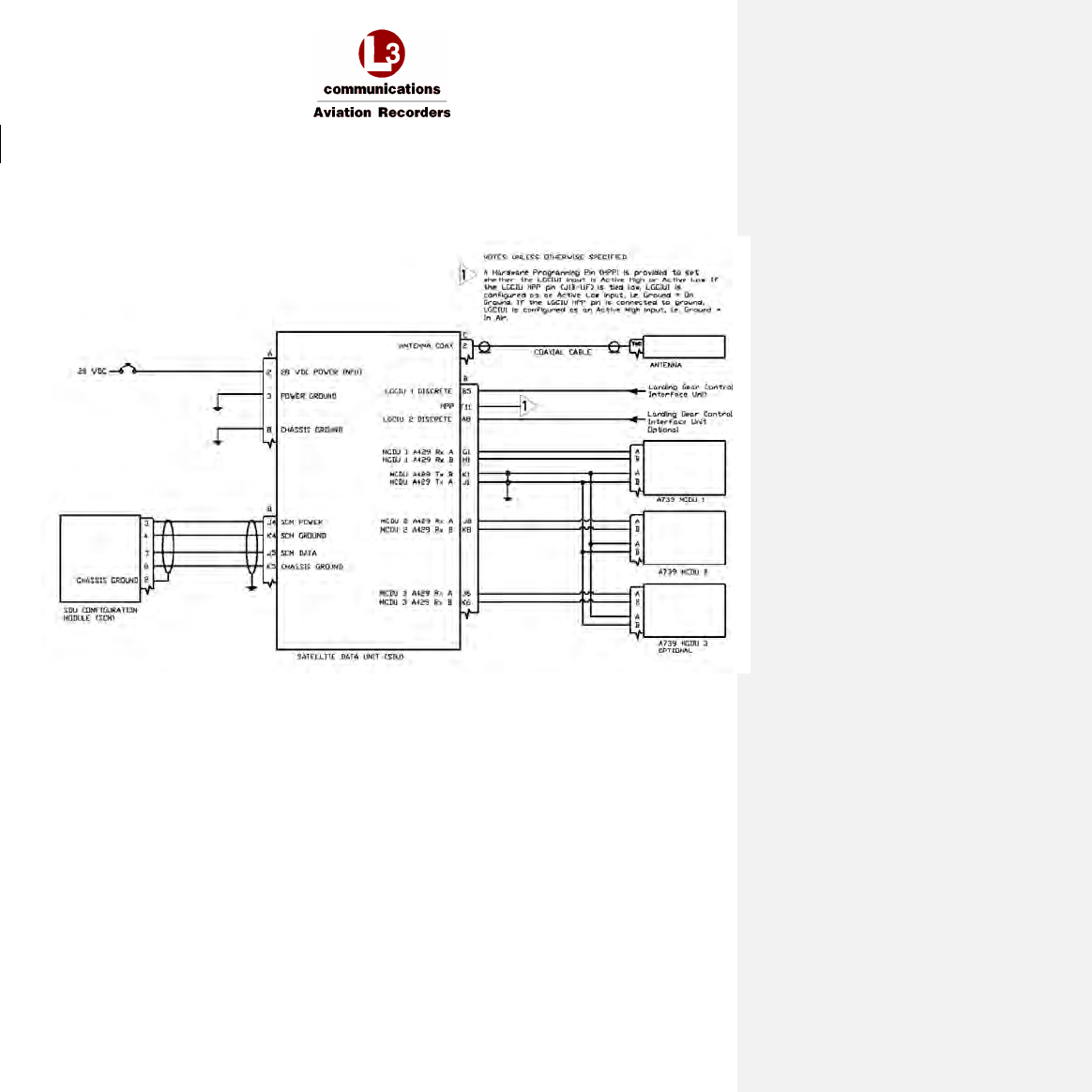
AFIRS 228S Iridium
Global Communications System Installation Manual
16 July 2014 L-3 Aviation Recorders Proprietary Appendix
165E5733-00 Rev. 03 Page 1
Appendix A – Wiring Diagram
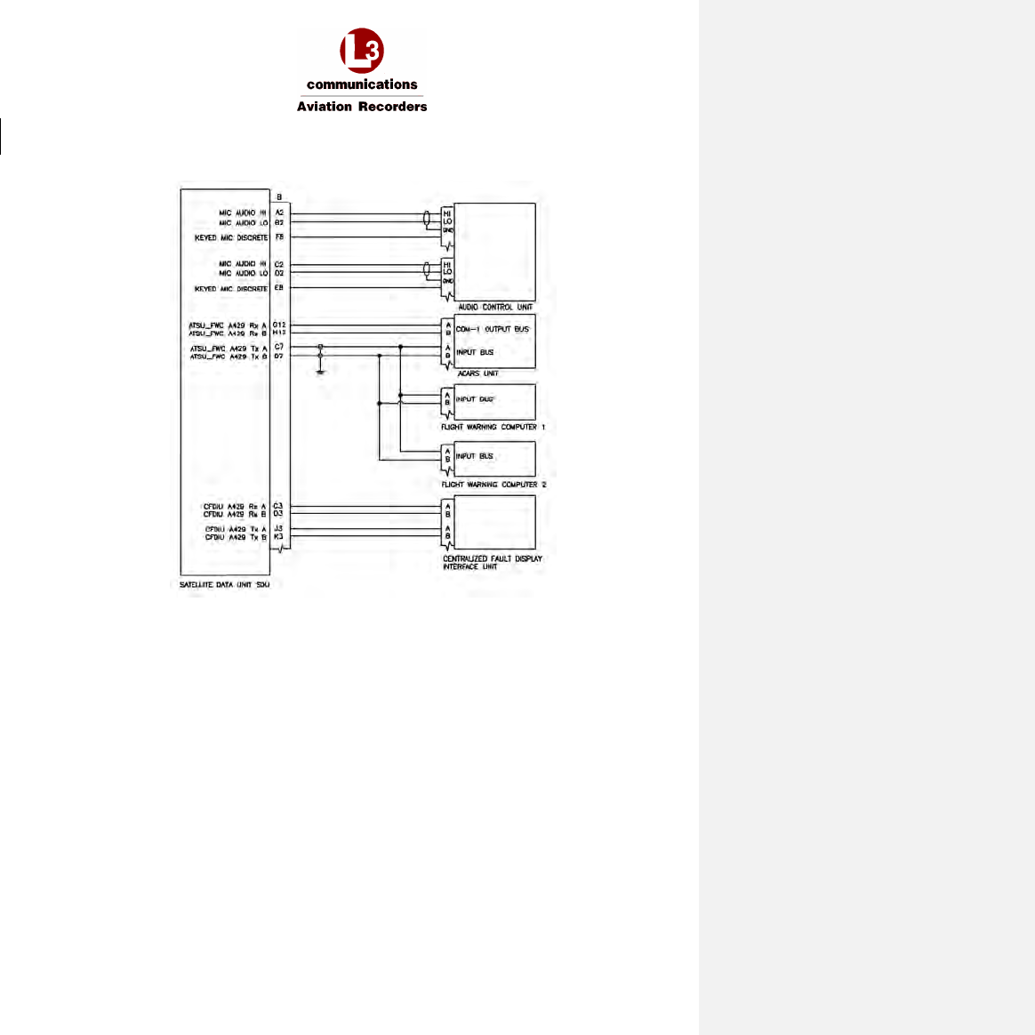
AFIRS 228S Iridium
Global Communications System Installation Manual
16 July 2014 L-3 Aviation Recorders Proprietary Appendix
165E5733-00 Rev. 03 Page 2
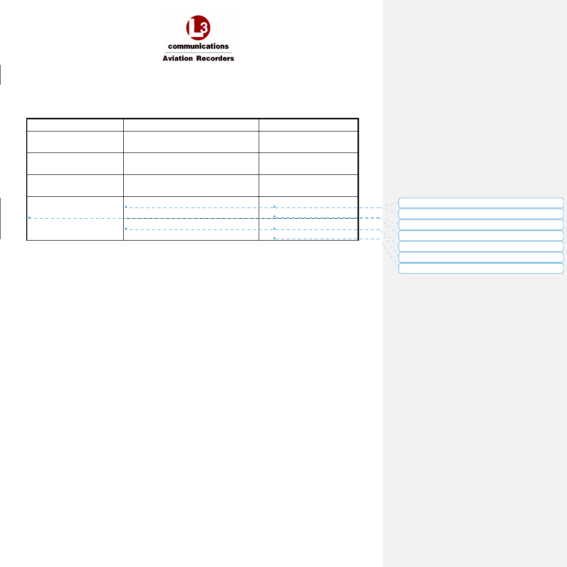
AFIRS 228S Iridium
Global Communications System Installation Manual
16 July 2014 L-3 Aviation Recorders Proprietary Appendix
165E5733-00 Rev. 03 Page 3
Appendix B – ORT Configuration Worksheet
ORT Group
ORT Parameter Name
Value
Air to Ground Calls
Call Progress Tones
NORTH AMERICAN
EUROPEAN
Allow Manual Dialing
Ext
ension
1
YES
NO
Other Call Parameters Allow Low Priority Calls in Cockpit YES
NO
Safety Services (Iridium
SATCOM System)
Additional ACARS Header Parameter
NONE
ARINC
ATS Enabled
YES
NO
Formatted: No underline
Formatted: No underline
Formatted: No underline
Formatted: No underline
Formatted: No underline
Formatted: No underline
Formatted: No underline

AFIRS 228S Iridium
Global Communications System Installation Manual
16 July 2014 L-3 Aviation Recorders Proprietary Appendix
165E5733-00 Rev. 03 Page 4
THIS PAGE INTENTIONALLY LEFT BLANK
AFIRS 228S Iridium
Global Communications System Installation Manual
16 July 2014 L-3 Aviation Recorders Proprietary Appendix
165E5733-00 Rev. 03 Page 1
Formatted: Right: -0.19"
Appendix C – System Faults
Iridium SATCOM Built-In-Tests (BIT)
Most of the checks are run as part of the Power-On Self-Test (POST) functionality or the Continuous Built-In Test (C-BIT) functionality.
- POST checks are run when the system is in Initialization Mode
- C-BIT checks are run at regular intervals during Operational Mode and Maintenance Mode
As BIT Checks are performed, the system will identify any "Raise Fault/Failure" conditions (system errors) that will affect functionality.
Sometimes an error can cleared immediately, and there will be no record of it in the fault log. If a system error cannot be resolved immediately,
a Failure, Fault, or Status Message will be recorded and tagged with the specific Date, Time, Position (DTP), and the value will be stored as the
ORT Aircraft ICAO Address parameter.
During the next periodic Continuous tests the system will determine if a recorded system error is still affecting functionality. If it is not, the
Failure, Fault, or Status Message may be cleared. In the event that a condition is cleared, the system will record it as cleared, and tag it with the
specific Date, Time, Position and the value of the associated ORT Aircraft ICAO Address parameter.
Data Area Checks: Ensures that the various data areas utilized by the Iridium SATCOM system are accessible
Power Checks: Monitors voltage inputs to the Iridium SATCOM system and internal voltage rails of the power supply
Temperature Checks: Responds to system critical temperatures reported by the temperature sensors built into the SDU
Internal Interface Checks: Monitors communication with system devices, including the Internal GPS, ISVM, ISDM, the SCM
External Interface Checks: Monitors communication between the Iridium SATCOM system and external systems
Satellite Link Checks: Monitors the availability of the GPS and Iridium satellite links
Formatted Table
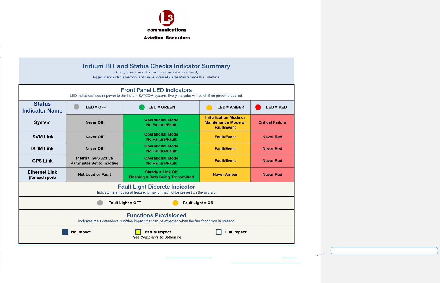
AFIRS 228S Iridium
Global Communications System Installation Manual
16 July 2014 L-3 Aviation Recorders Proprietary Appendix
165E5733-00 Rev. 03 Page 2
Formatted: Right: -0.19"
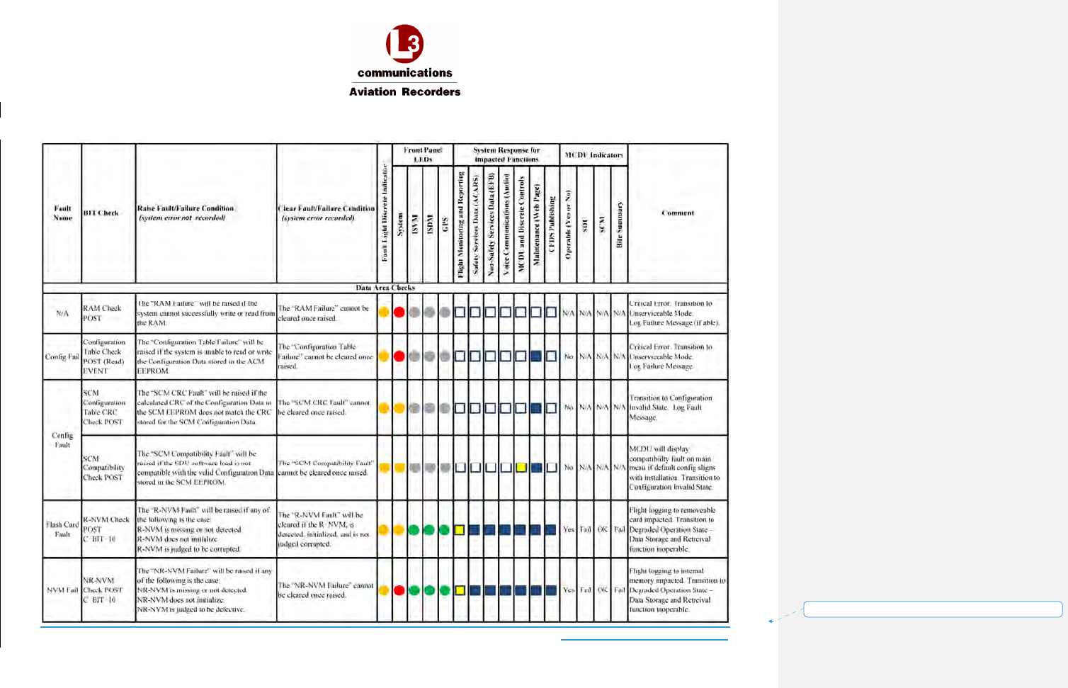
AFIRS 228S Iridium
Global Communications System Installation Manual
16 July 2014 L-3 Aviation Recorders Proprietary Appendix
165E5733-00 Rev. 03 Page 3
Formatted: Right: -0.19"
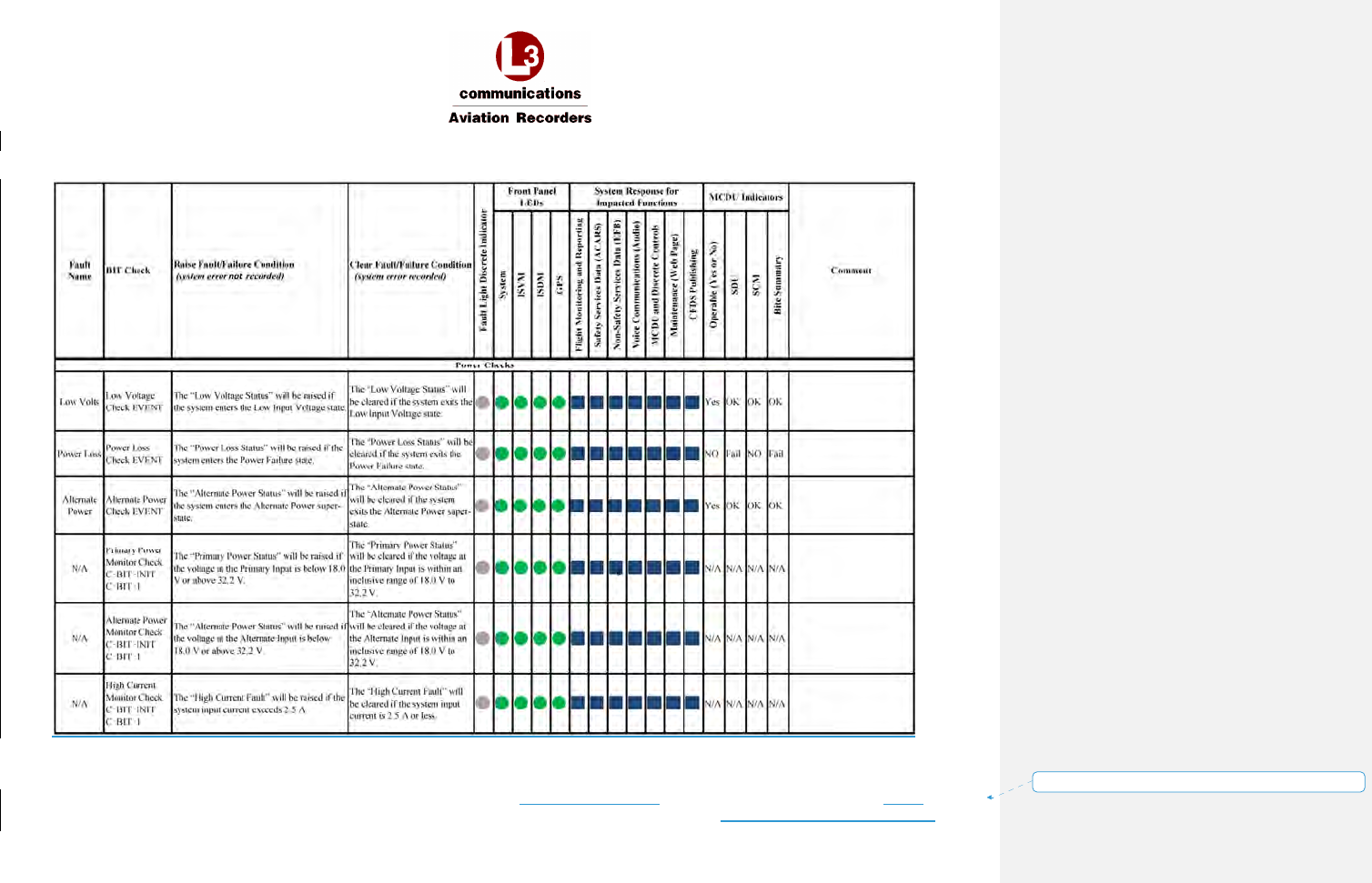
AFIRS 228S Iridium
Global Communications System Installation Manual
16 July 2014 L-3 Aviation Recorders Proprietary Appendix
165E5733-00 Rev. 03 Page 4
Formatted: Right: -0.19"
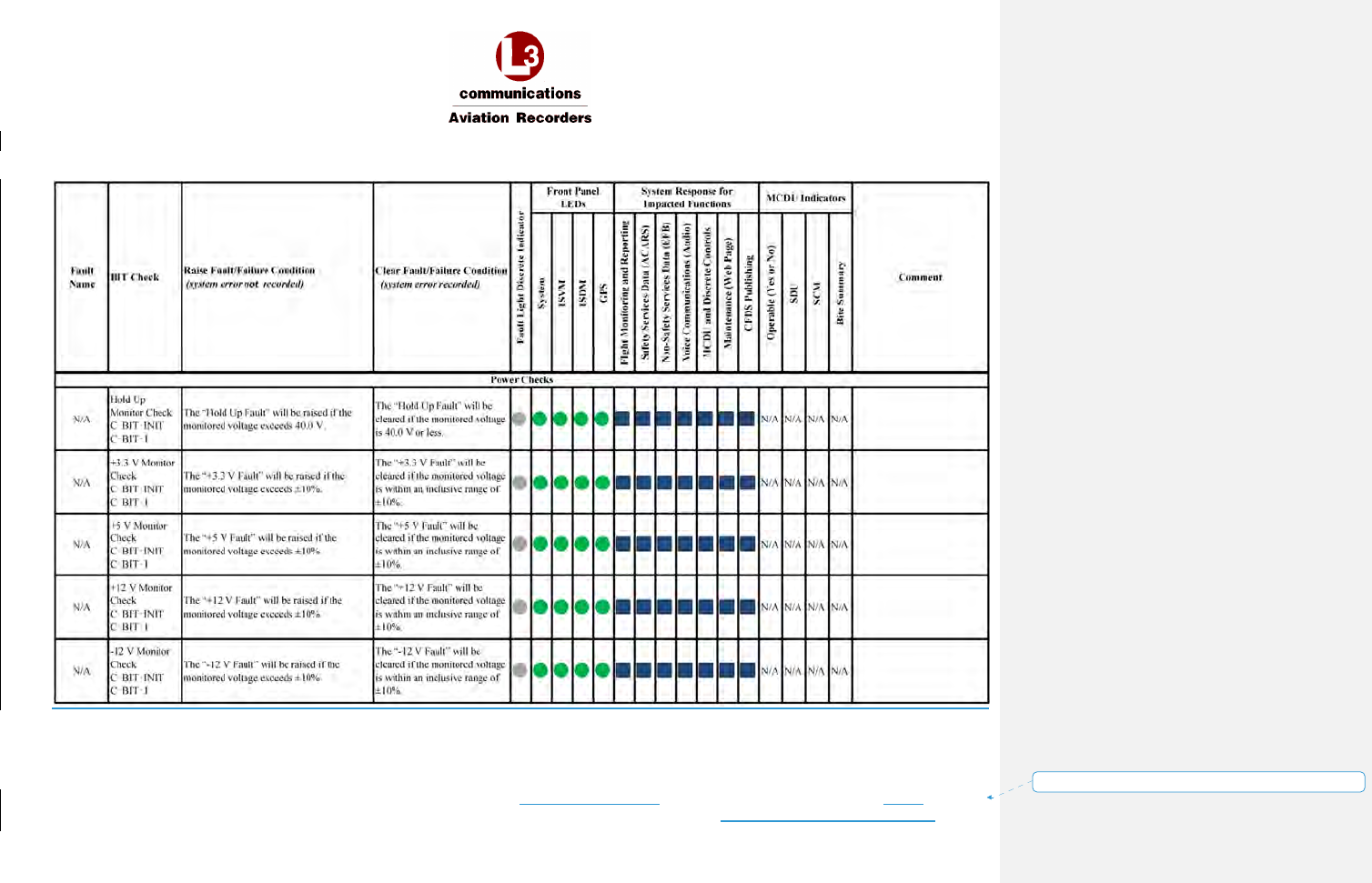
AFIRS 228S Iridium
Global Communications System Installation Manual
16 July 2014 L-3 Aviation Recorders Proprietary Appendix
165E5733-00 Rev. 03 Page 5
Formatted: Right: -0.19"
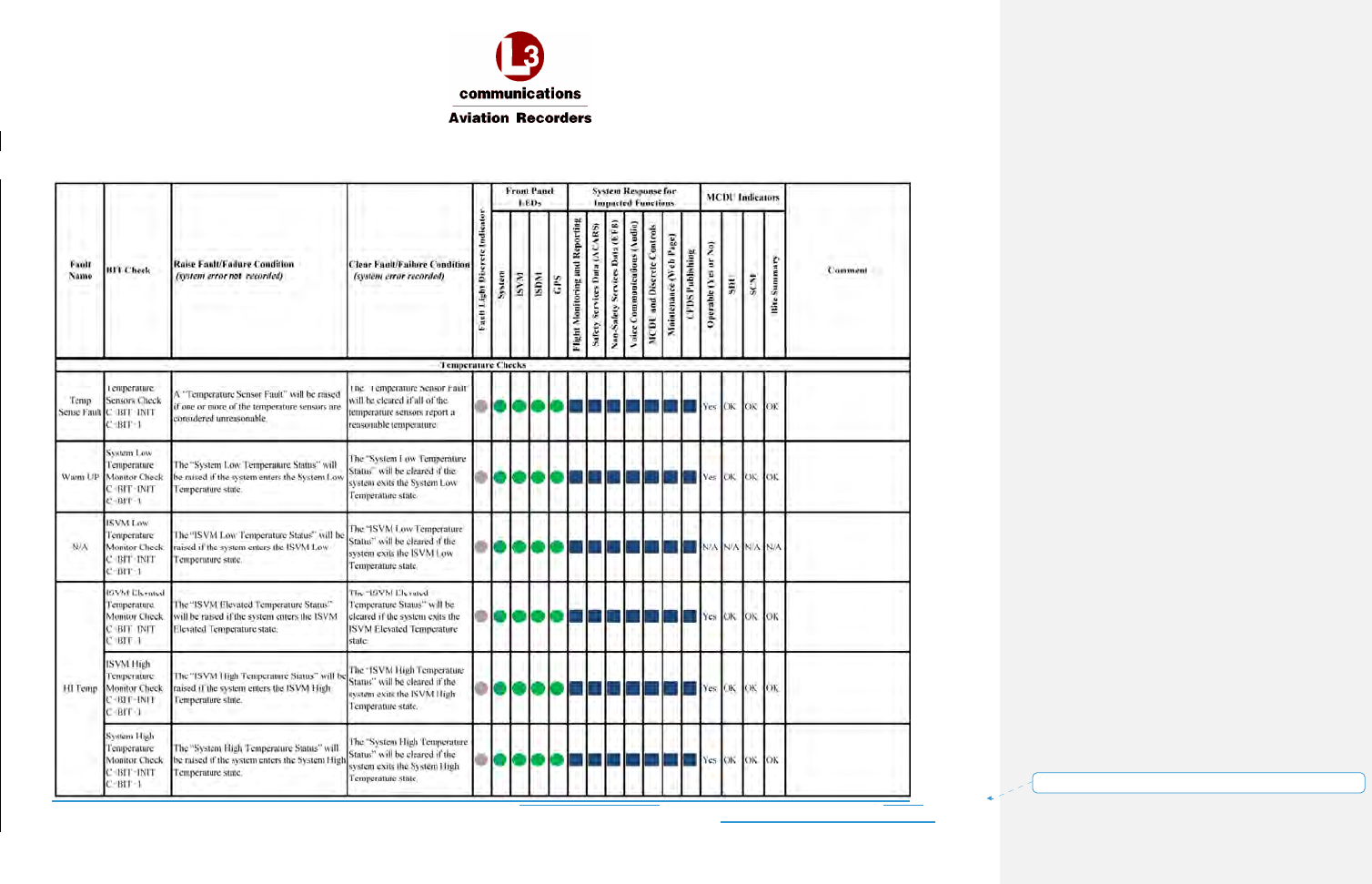
AFIRS 228S Iridium
Global Communications System Installation Manual
16 July 2014 L-3 Aviation Recorders Proprietary Appendix
165E5733-00 Rev. 03 Page 6
Formatted: Right: -0.19"
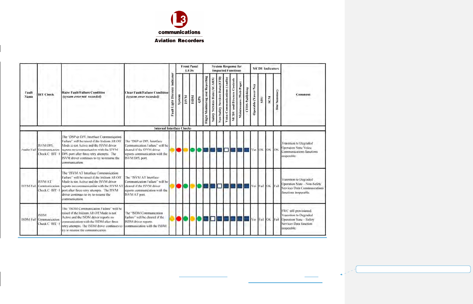
AFIRS 228S Iridium
Global Communications System Installation Manual
16 July 2014 L-3 Aviation Recorders Proprietary Appendix
165E5733-00 Rev. 03 Page 7
Formatted: Right: -0.19"
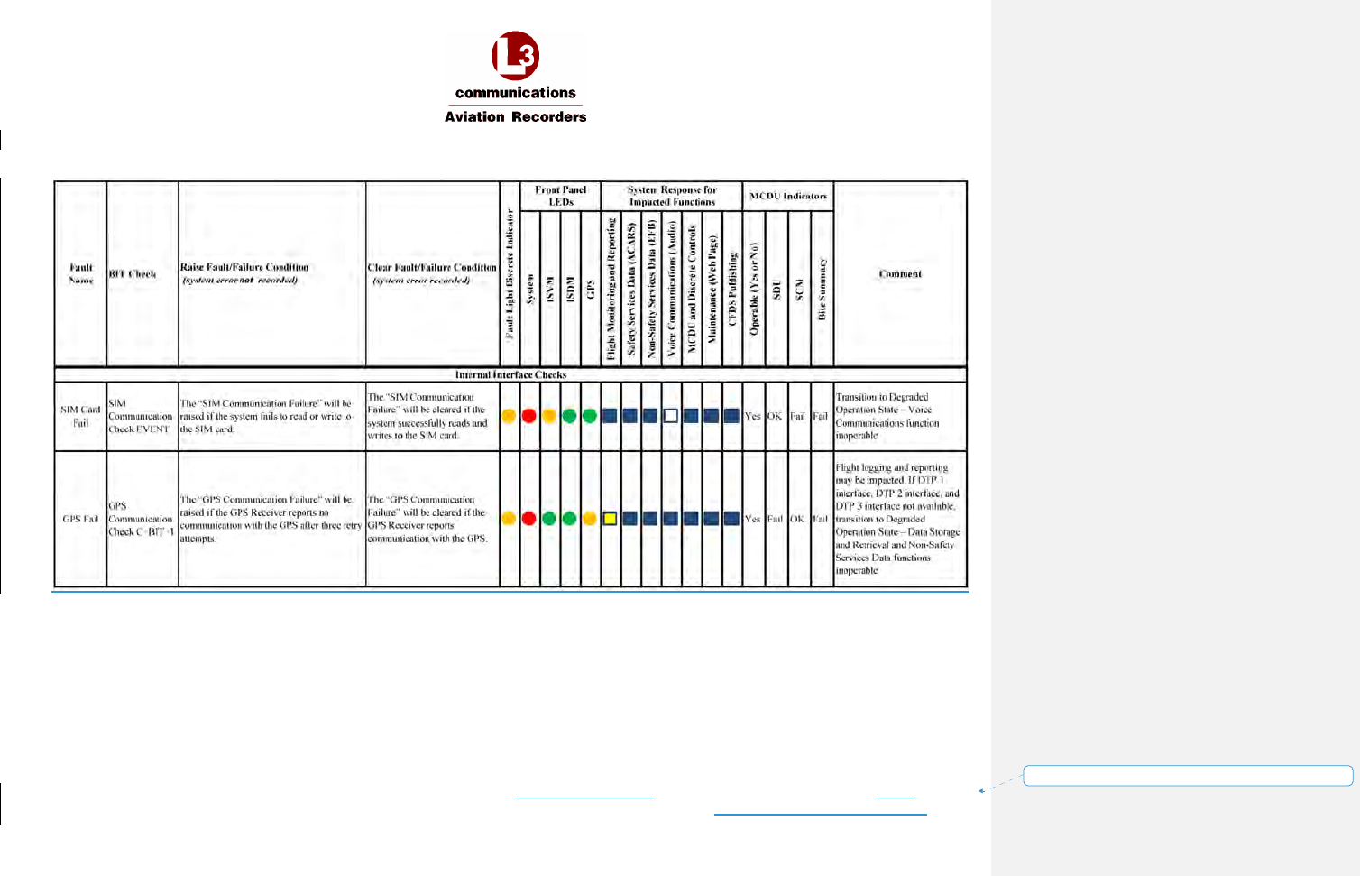
AFIRS 228S Iridium
Global Communications System Installation Manual
16 July 2014 L-3 Aviation Recorders Proprietary Appendix
165E5733-00 Rev. 03 Page 8
Formatted: Right: -0.19"
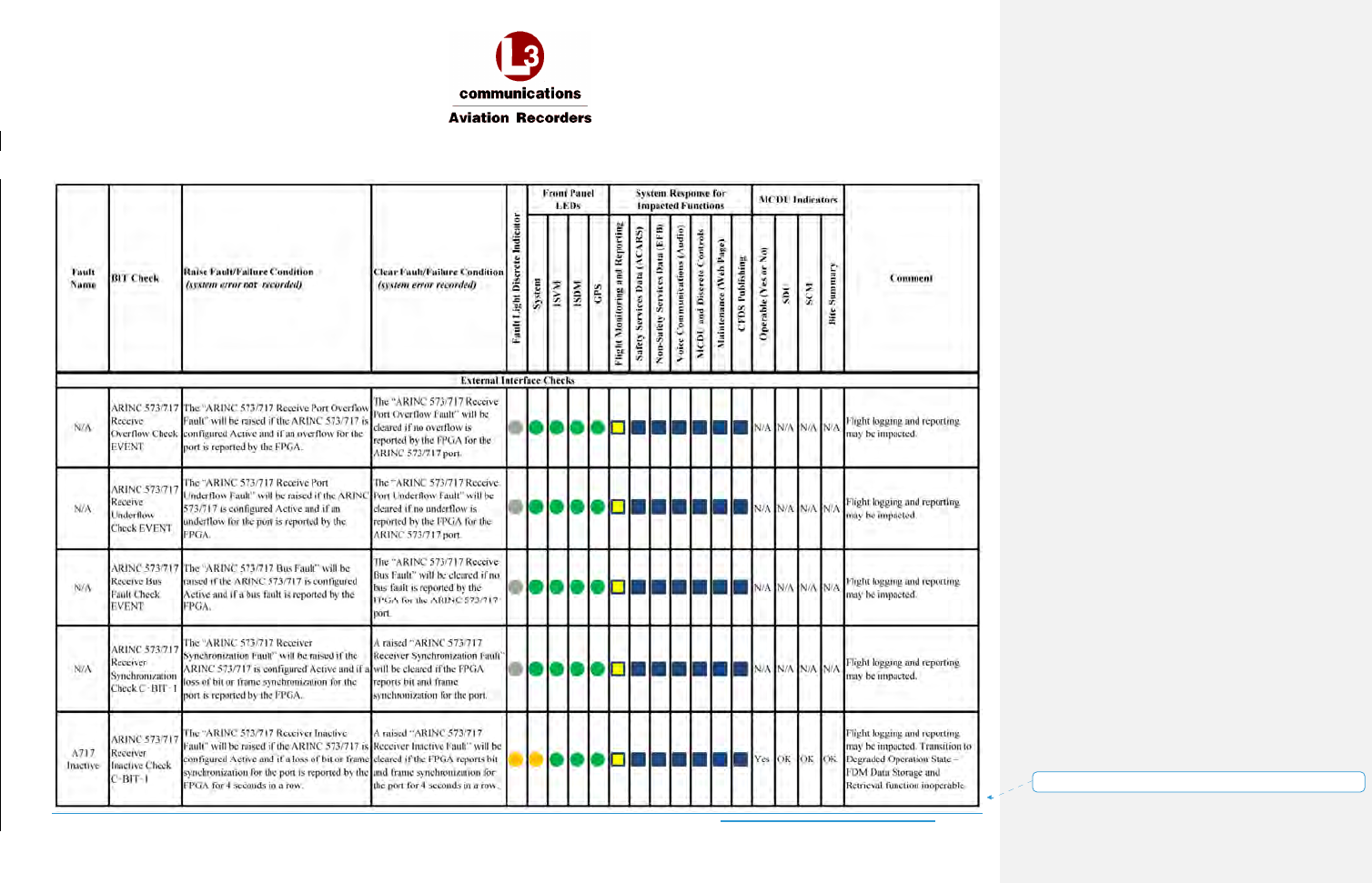
AFIRS 228S Iridium
Global Communications System Installation Manual
16 July 2014 L-3 Aviation Recorders Proprietary Appendix
165E5733-00 Rev. 03 Page 9
Formatted: Right: -0.19"
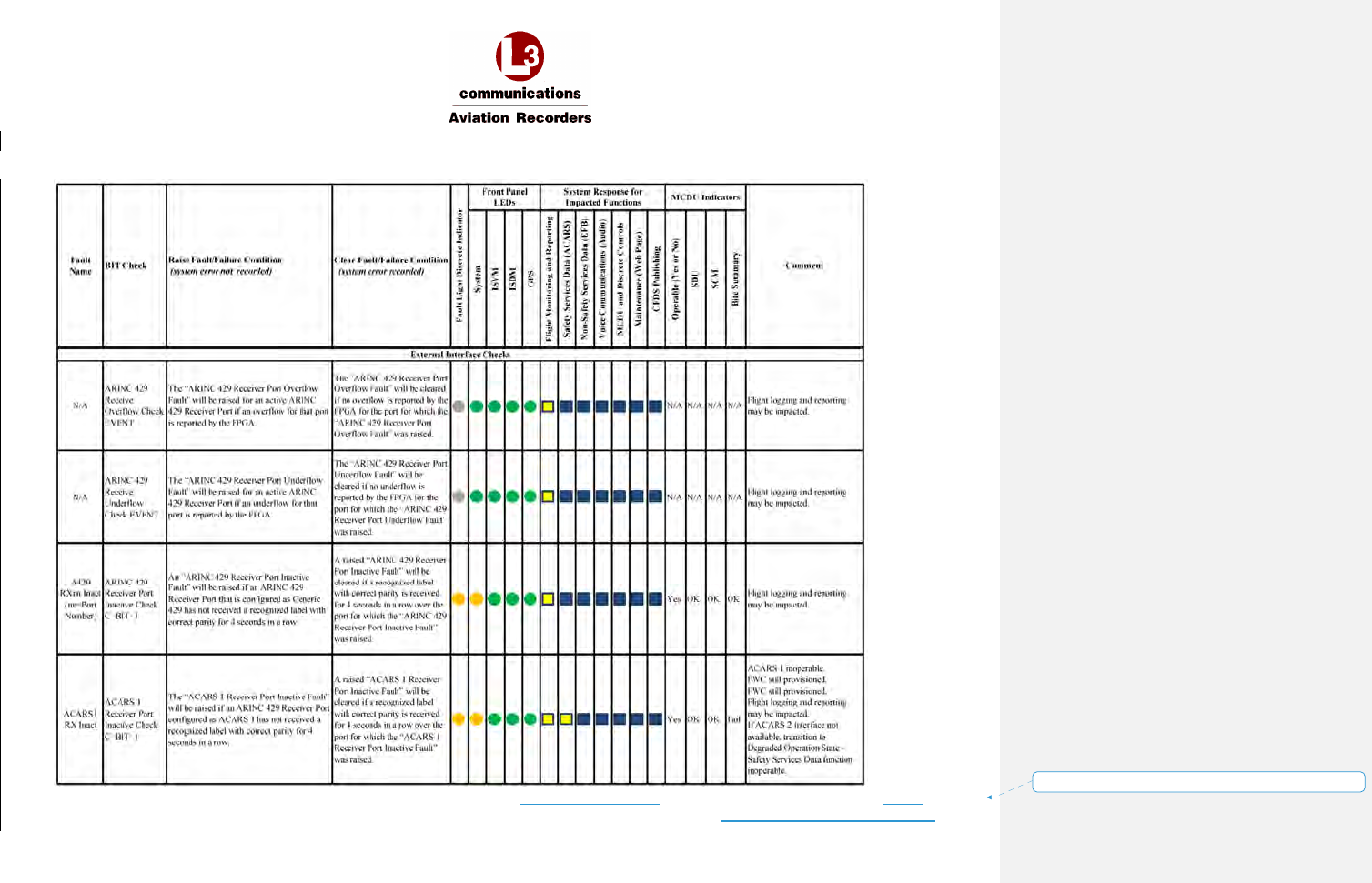
AFIRS 228S Iridium
Global Communications System Installation Manual
16 July 2014 L-3 Aviation Recorders Proprietary Appendix
165E5733-00 Rev. 03 Page 10
Formatted: Right: -0.19"
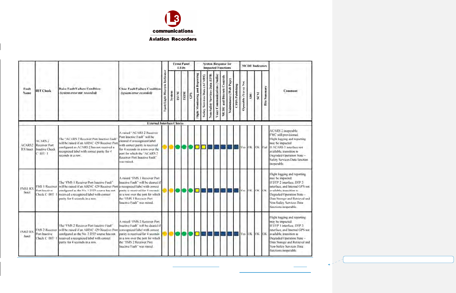
AFIRS 228S Iridium
Global Communications System Installation Manual
16 July 2014 L-3 Aviation Recorders Proprietary Appendix
165E5733-00 Rev. 03 Page 11
Formatted: Right: -0.19"
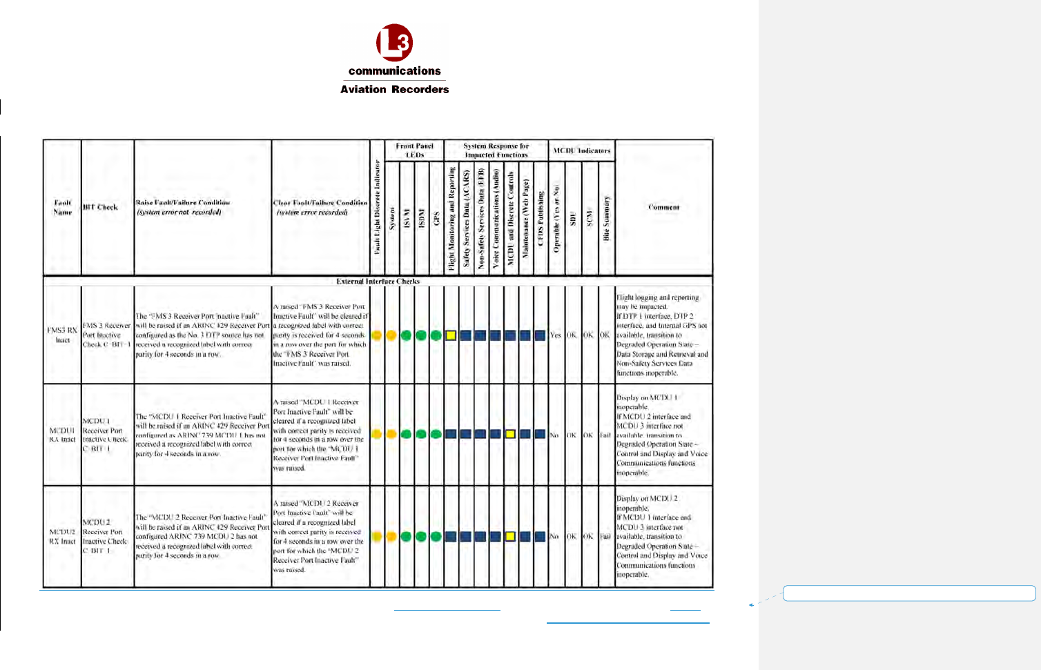
AFIRS 228S Iridium
Global Communications System Installation Manual
16 July 2014 L-3 Aviation Recorders Proprietary Appendix
165E5733-00 Rev. 03 Page 12
Formatted: Right: -0.19"
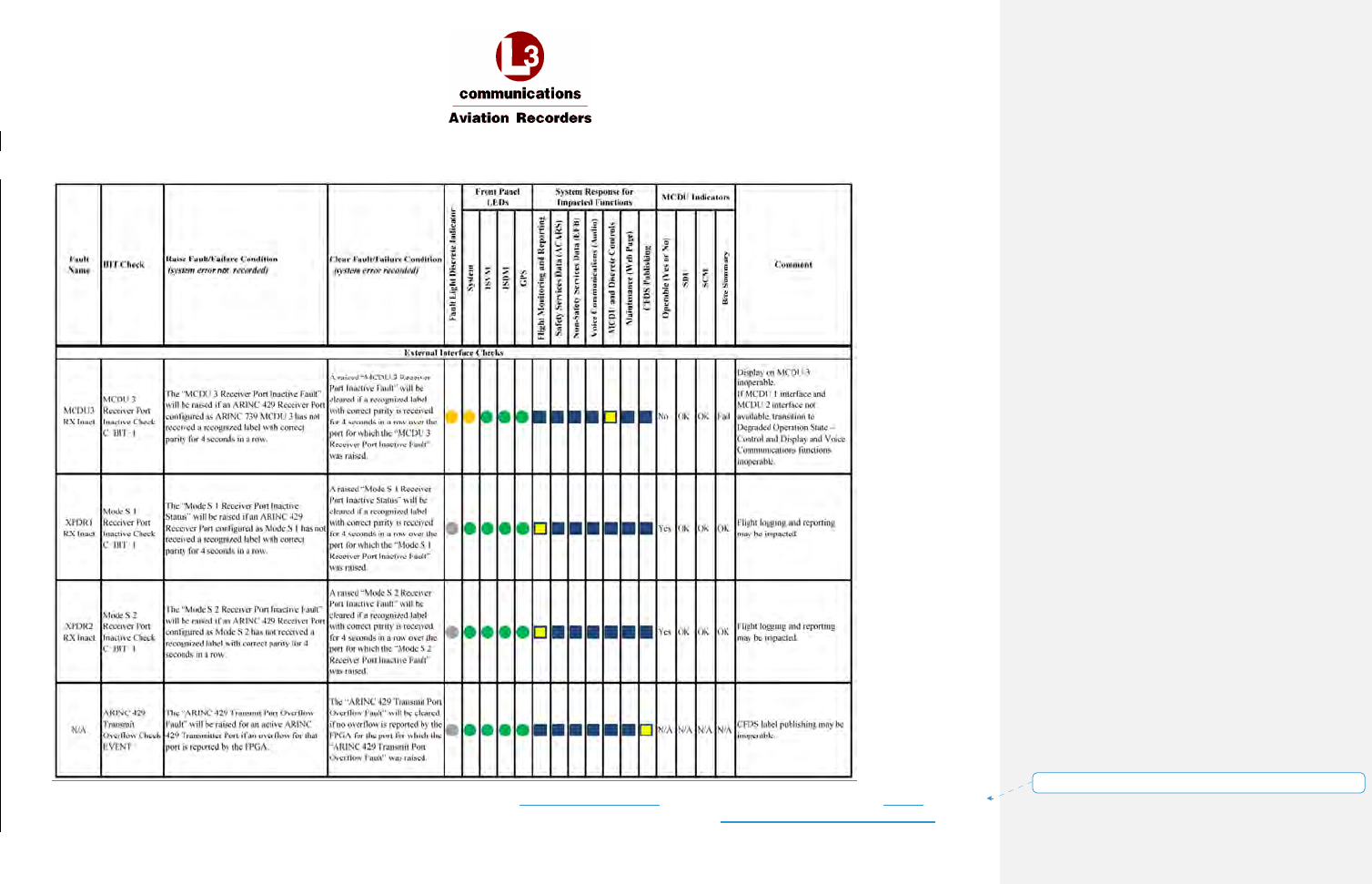
AFIRS 228S Iridium
Global Communications System Installation Manual
16 July 2014 L-3 Aviation Recorders Proprietary Appendix
165E5733-00 Rev. 03 Page 13
Formatted: Right: -0.19"
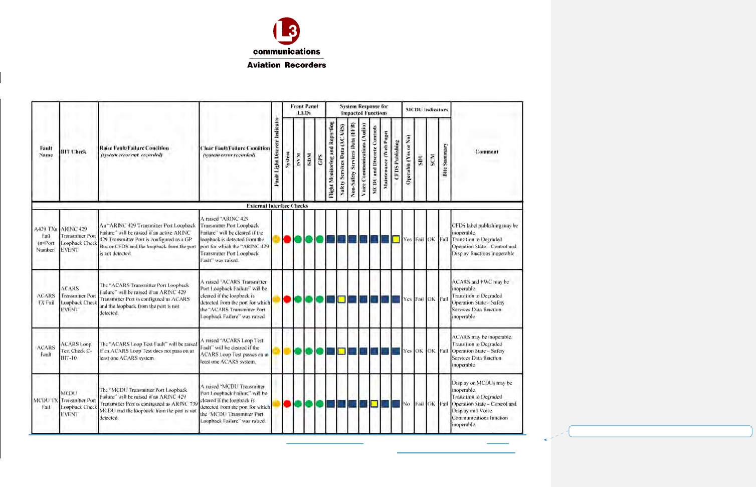
AFIRS 228S Iridium
Global Communications System Installation Manual
16 July 2014 L-3 Aviation Recorders Proprietary Appendix
165E5733-00 Rev. 03 Page 14
Formatted: Right: -0.19"
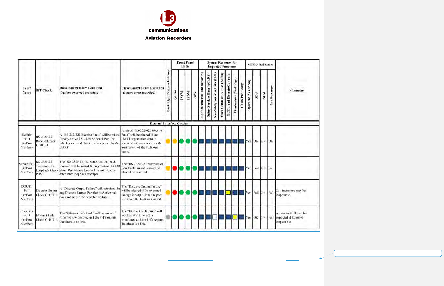
AFIRS 228S Iridium
Global Communications System Installation Manual
16 July 2014 L-3 Aviation Recorders Proprietary Appendix
165E5733-00 Rev. 03 Page 15
Formatted: Right: -0.19"
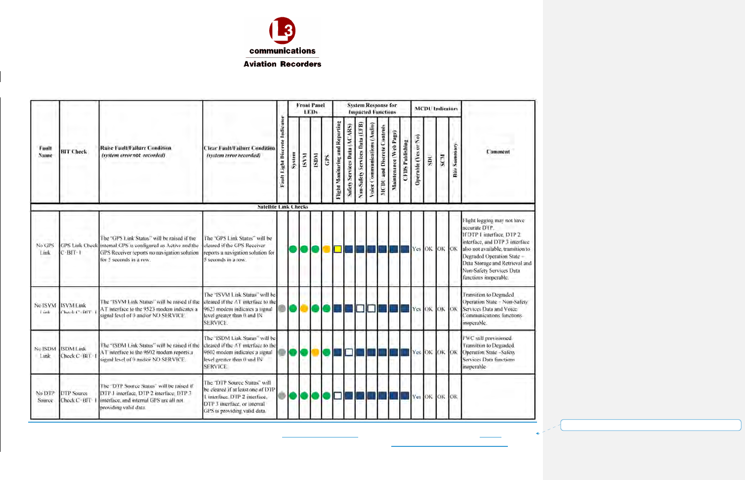
AFIRS 228S Iridium
Global Communications System Installation Manual
16 July 2014 L-3 Aviation Recorders Proprietary Appendix
165E5733-00 Rev. 03 Page 16
Formatted: Right: -0.19"
AFIRS 228S Iridium
Global Communications System Installation Manual
16 July 2014 L-3 Aviation Recorders Proprietary Appendix
165E5733-00 Rev. 03 Page 17
Formatted: Right: -0.19"
THIS PAGE INTENTIONALLY LEFT BLANK
AFIRS 228S Iridium
Global Communications System Installation Manual
16 July 2014 L-3 Aviation Recorders Proprietary Supplemental Documents
165E5733-00 Rev. 03 Page 1
Supplemental Documents
Document
Number
Date Description
905-E5750-63
Rev. A
10/2/14 Environmental Qualification Form –
AFIRS 228S Satellite Data Unit and Satellite Control Module
AFIRS 228S Iridium
Global Communications System Installation Manual
16 July 2014 L-3 Aviation Recorders Proprietary Supplemental Documents
165E5733-00 Rev. 03 Page 2
THIS PAGE INTENTIONALLY LEFT BLANK