L3 Technologies AFIRS228S0 AFIRS 228S Satellite Data Unit User Manual Iridium SATCOM System Welcome Package
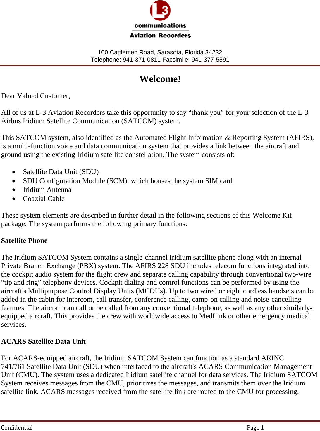
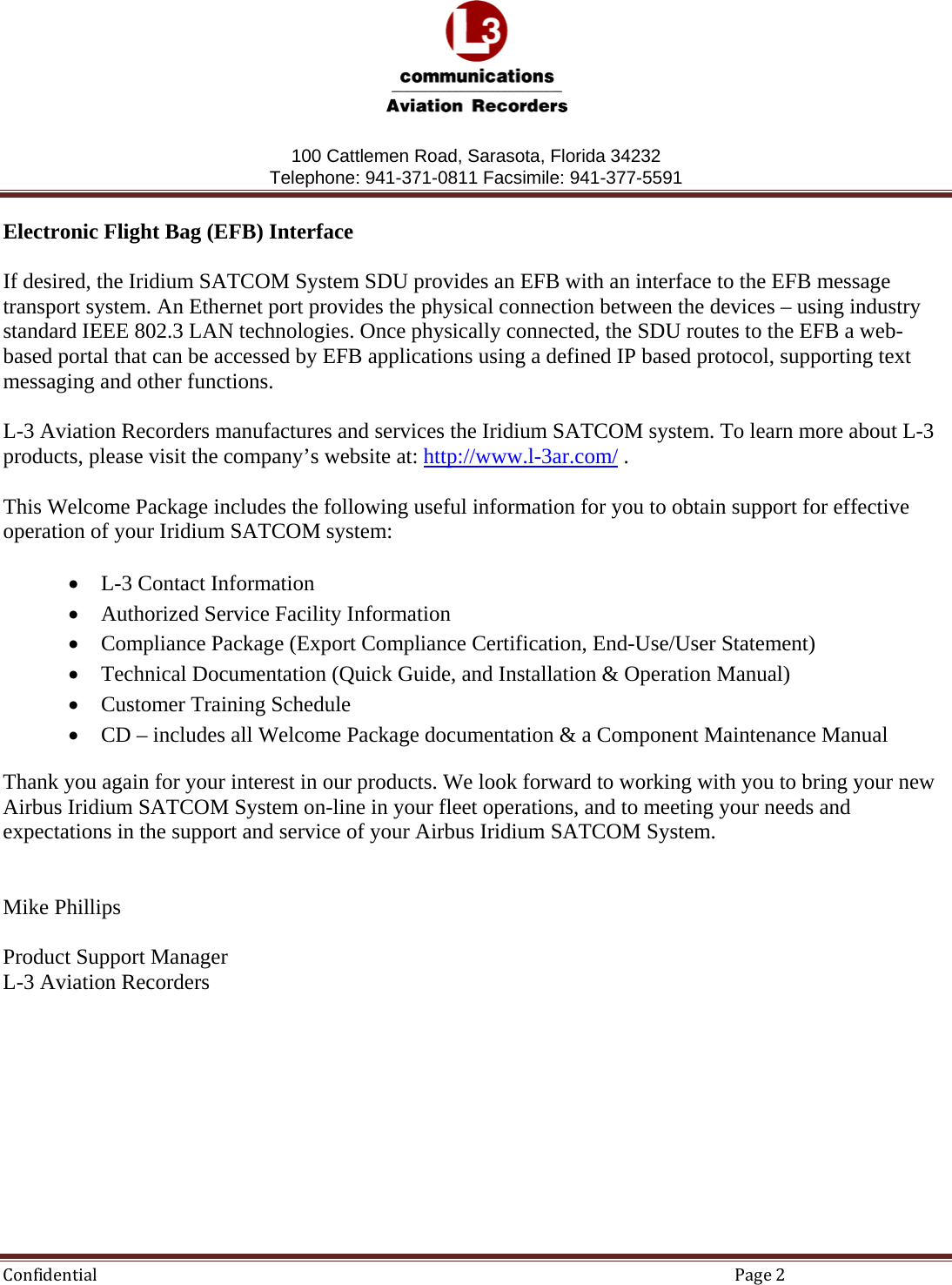
L3 Technologies AFIRS 228S Satellite Data Unit Iridium SATCOM System Welcome Package
UserManual.wiki
>
L3 Technologies
>
AFIRS228S0 User Manual
User Manual
Navigation menu
Upload a User Manual
Namespaces
Wiki Guide
HTML
PDF
Info
Views
User Manual
Discussion / Help
Navigation


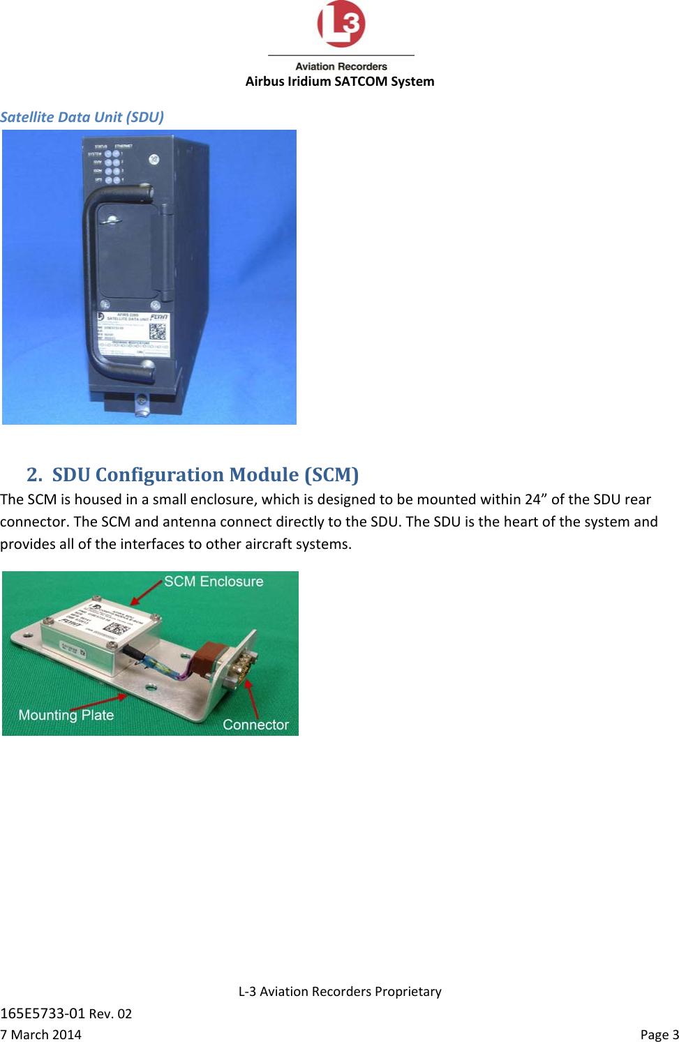
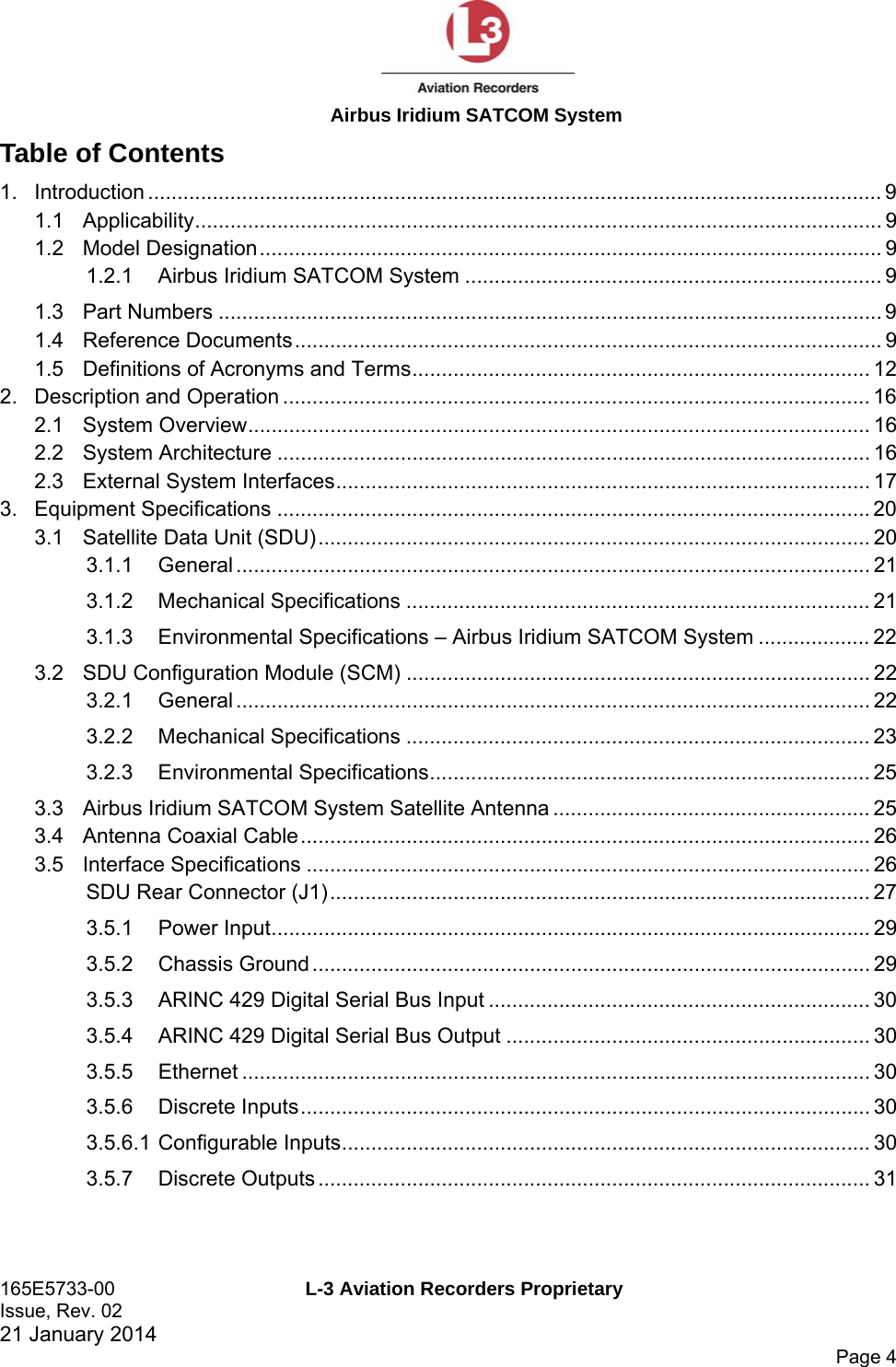

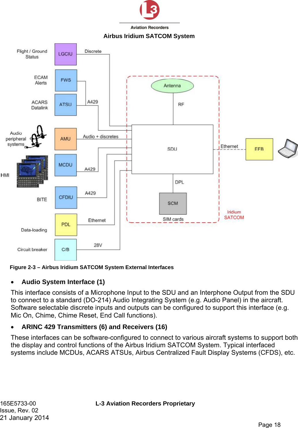
![Airbus Iridium SATCOM System 165E5733-00 L-3 Aviation Recorders Proprietary Issue, Rev. 02 21 January 2014 Page 21 3.1.1 General The SDU is housed in an ARINC 600 2MCU enclosure, which is designed to be mounted in a standard ARINC 600 mounting tray. See Figure 3-2 for an outline of this component. Figure 3-2 – SDU Outline Drawing (dimensions in [millimeters] and inches) 3.1.2 Mechanical Specifications Dimensions: 7.81” x 2.27” x 15.02” (198.3mm x 57.7mm x 381.5mm) (See Figure 3-2) Weight: 7.7 lbs. (3.49 kg) Max. Material/Finish: Aluminum Alloy with Black Polyurethane Finish](https://usermanual.wiki/L3-Technologies/AFIRS228S0/User-Guide-3659344-Page-58.png)
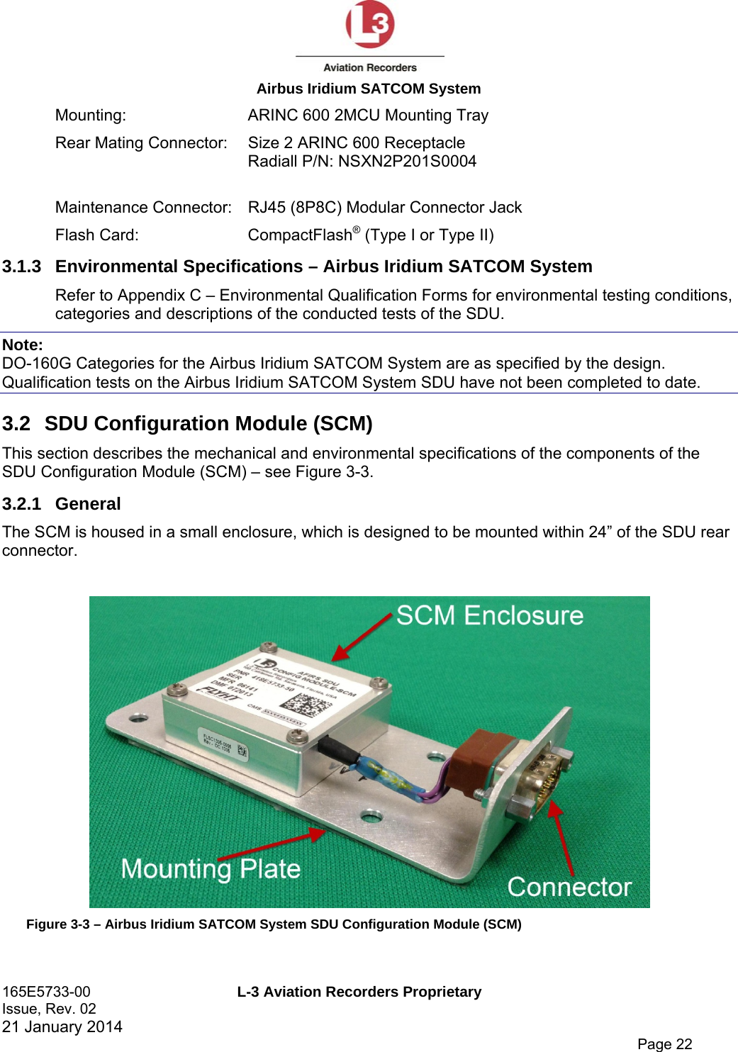
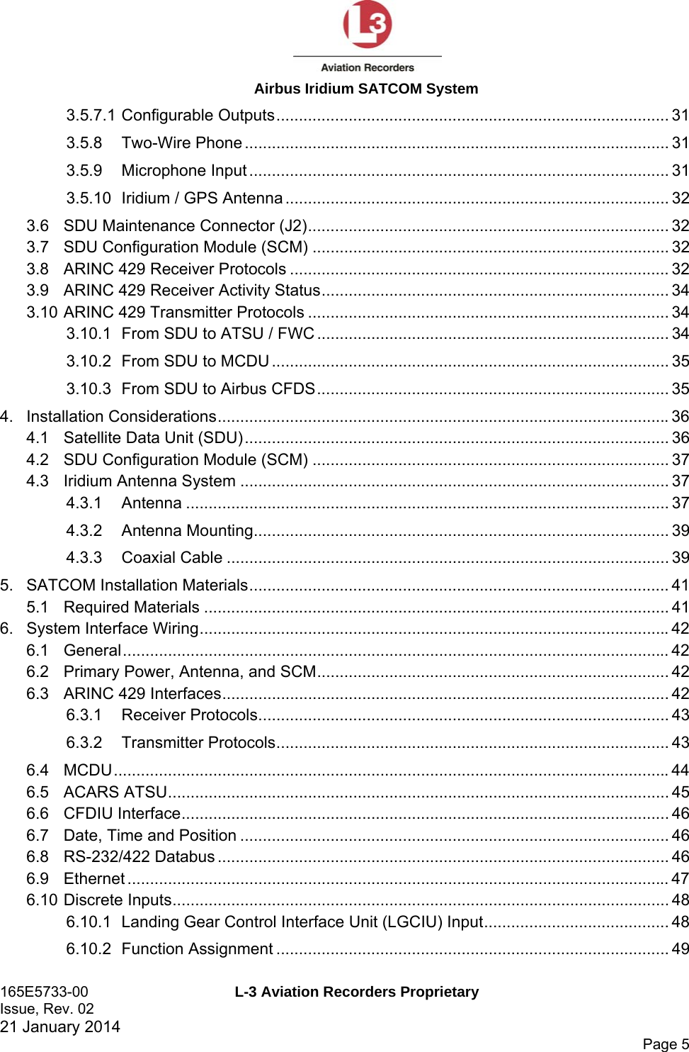
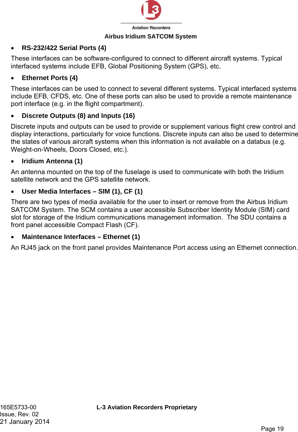
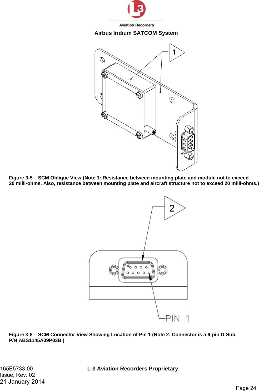
![Airbus Iridium SATCOM System 165E5733-00 L-3 Aviation Recorders Proprietary Issue, Rev. 02 21 January 2014 Page 23 Typically, the SCM will be mounted on or near the ARINC 600 mounting tray used for the SDU. See Figure 3-4 for an outline of this component. Figure 3-4 – SCM Outline Drawing (dimensions in [millimeters] and inches) 3.2.2 Mechanical Specifications Dimensions: 1.00” x 2.00” x 4.69” (25.4mm x 50.8mm x 119.1mm) Weight: 0.4 lbs. (0.18 kg) Max. Material/Finish: Aluminum alloy with clear chromate per MIL-DTL-5541, Type II, Class 3 on all surfaces](https://usermanual.wiki/L3-Technologies/AFIRS228S0/User-Guide-3659344-Page-60.png)
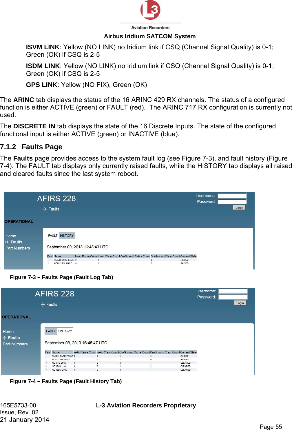
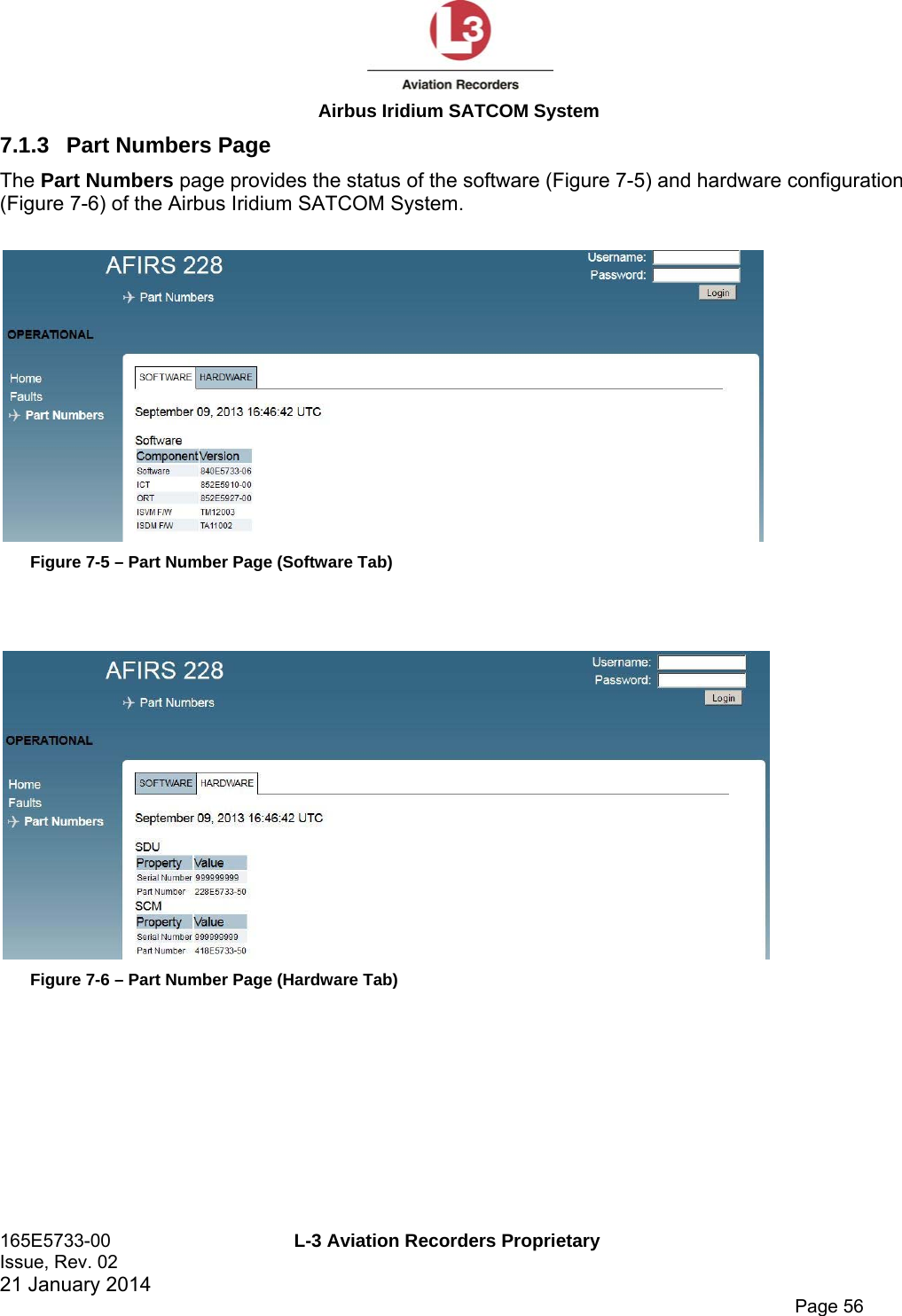
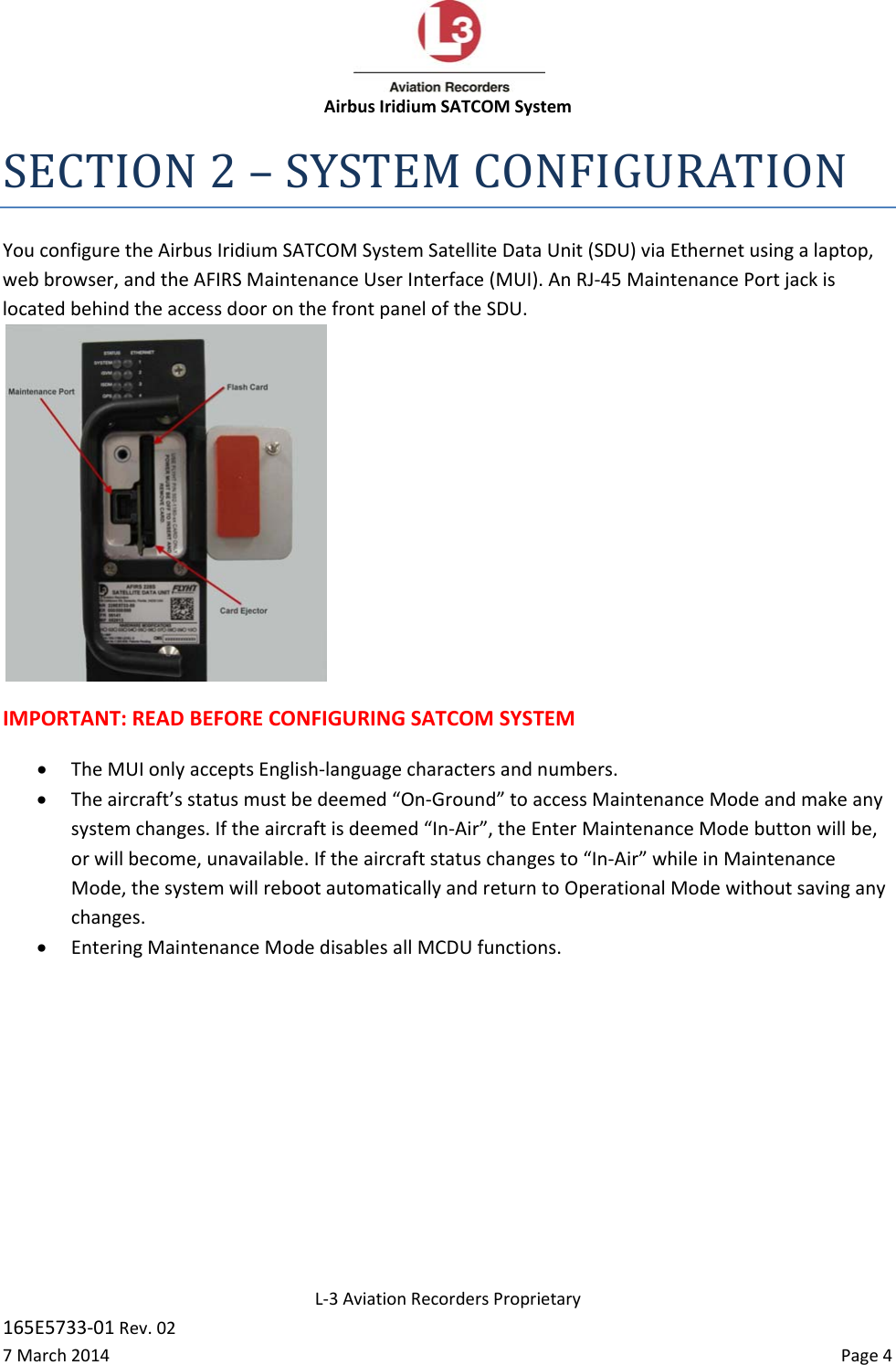
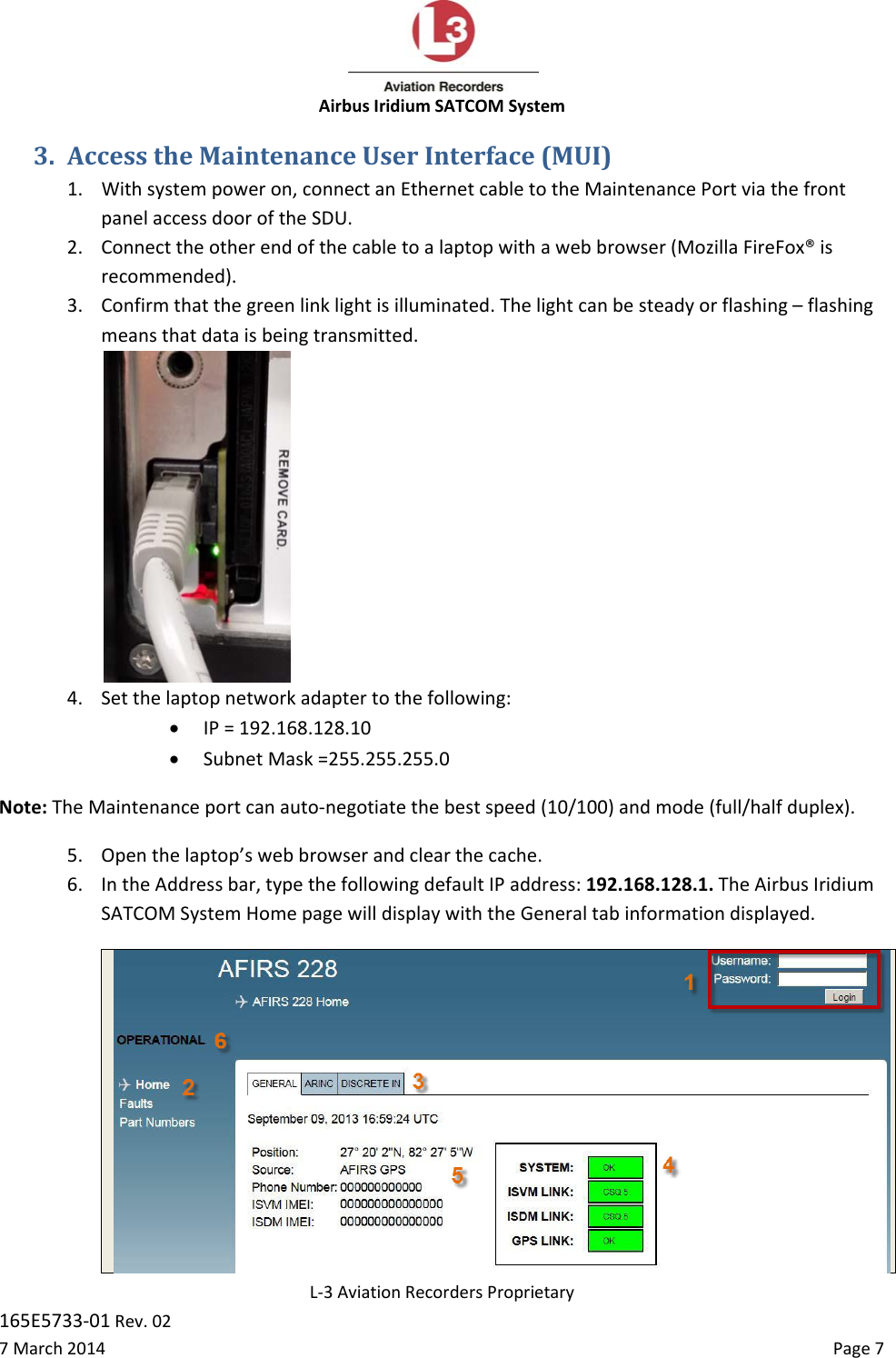
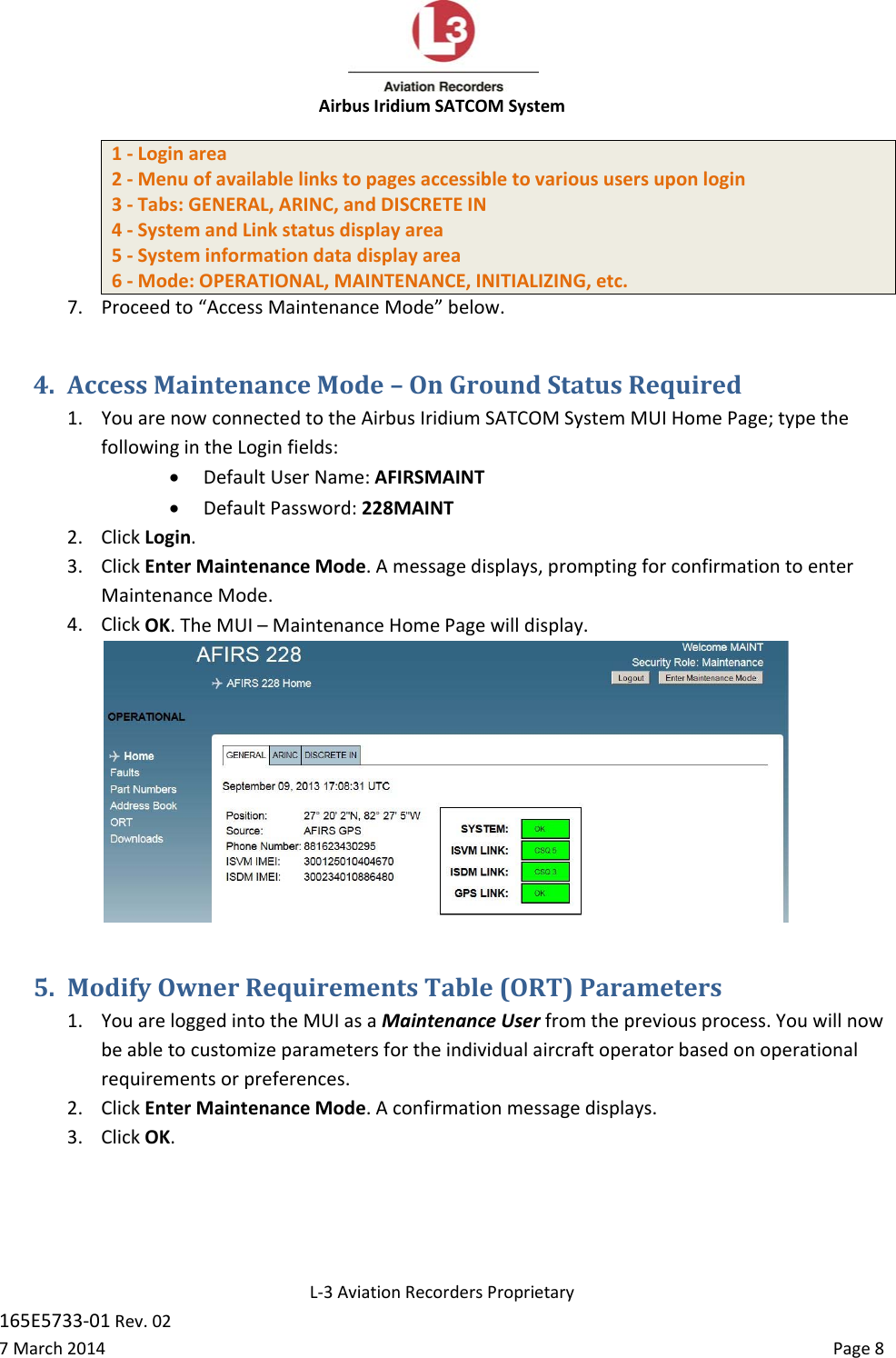
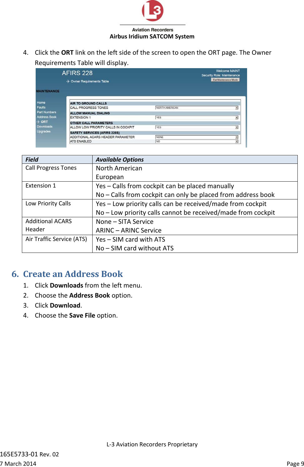
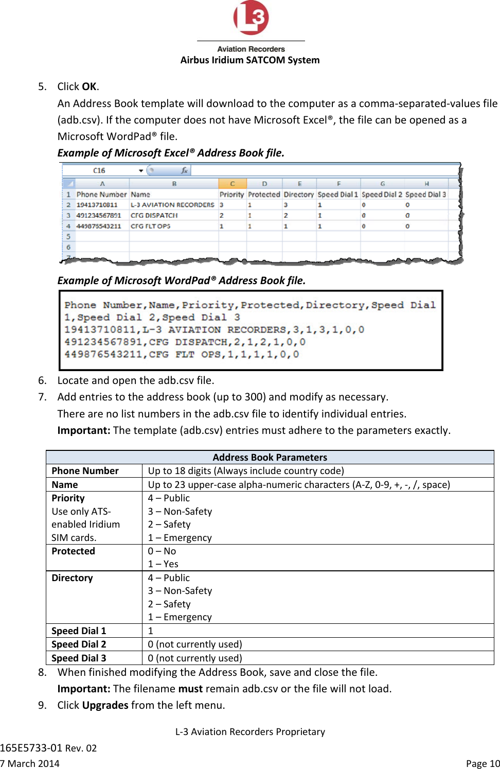
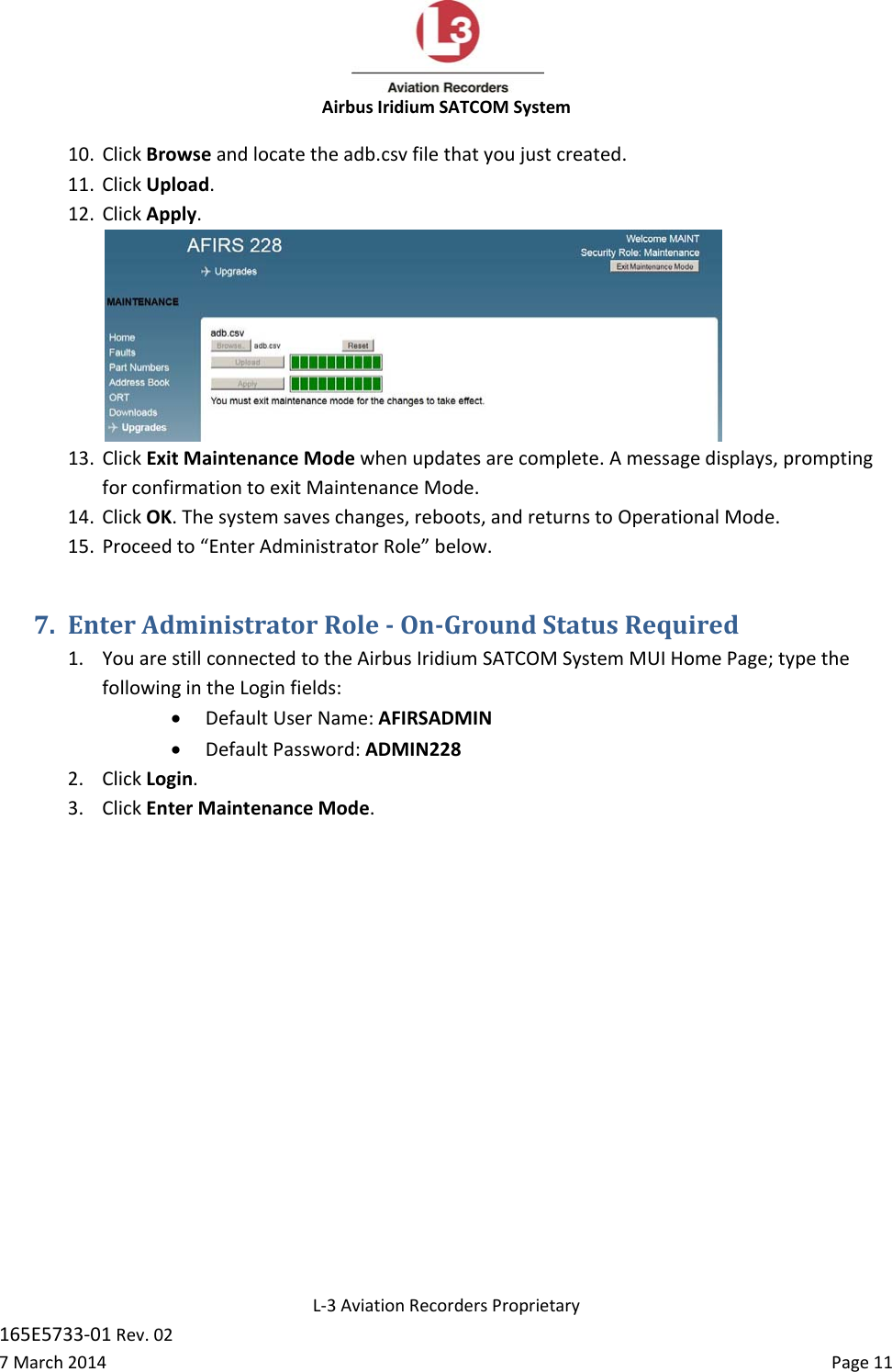
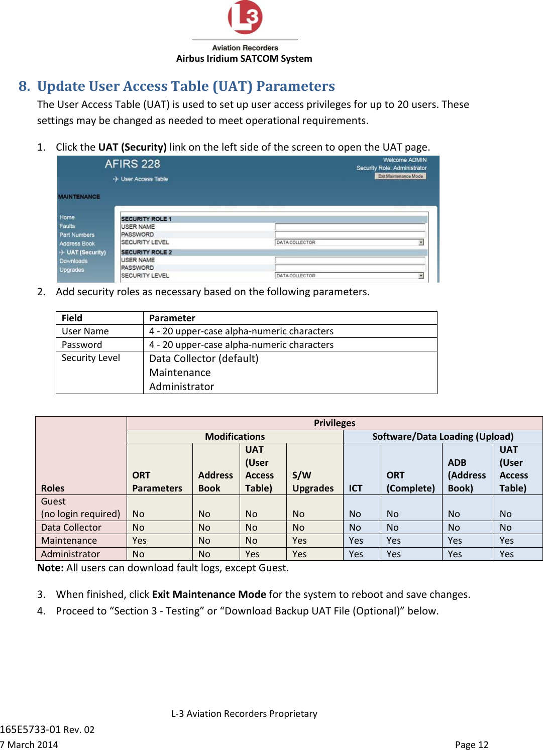
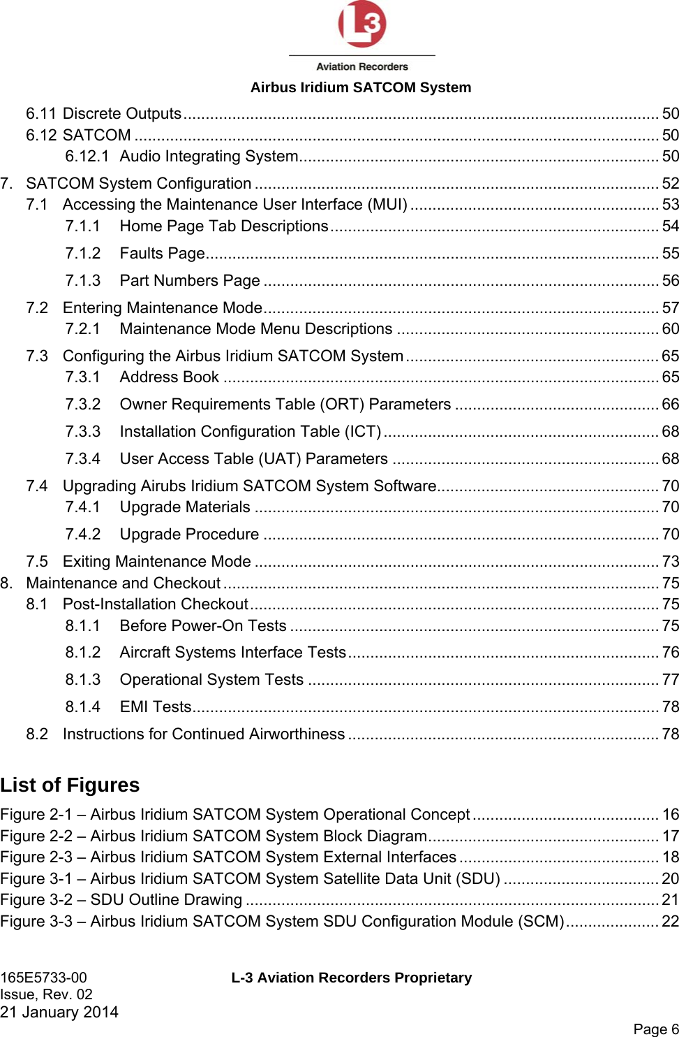
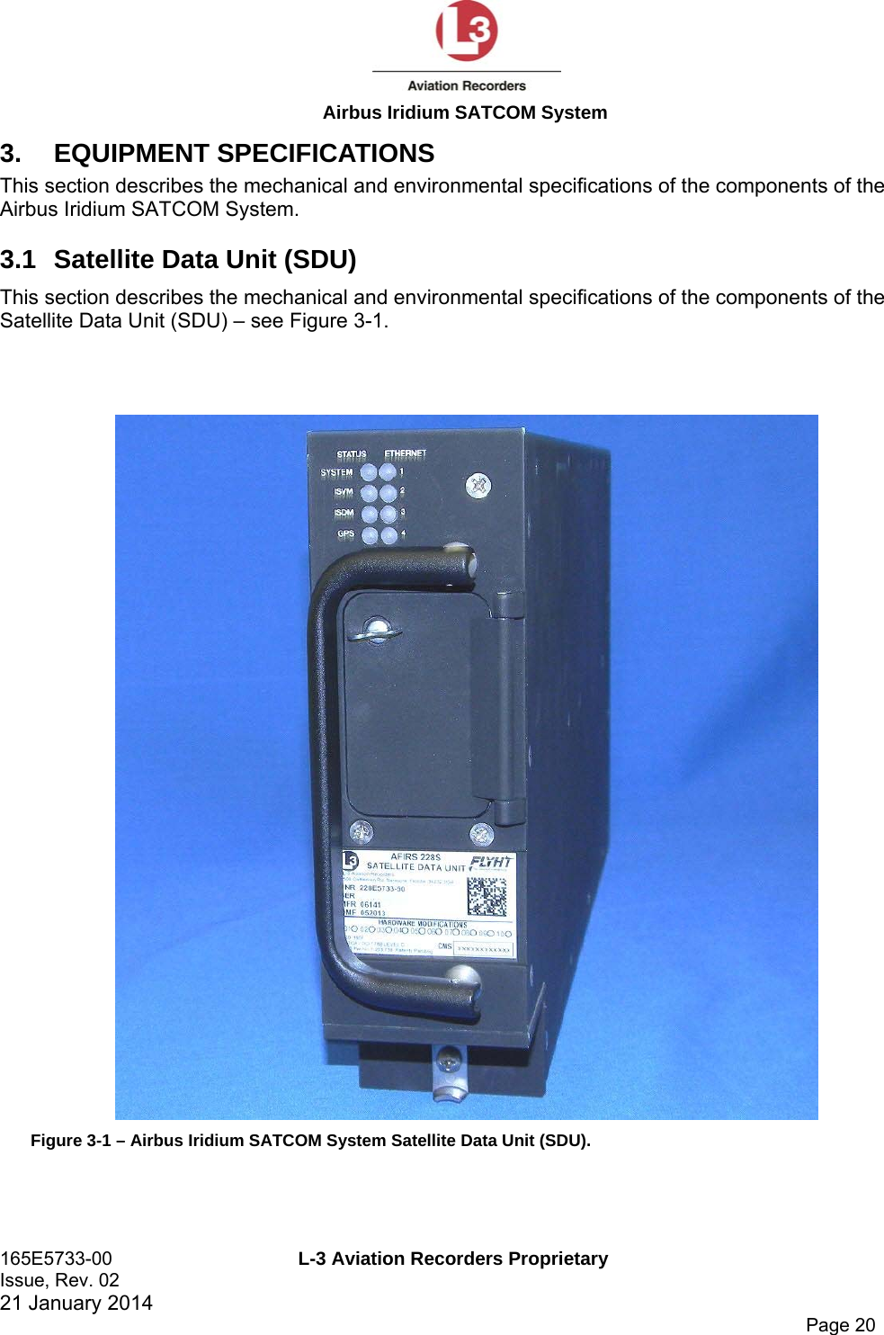
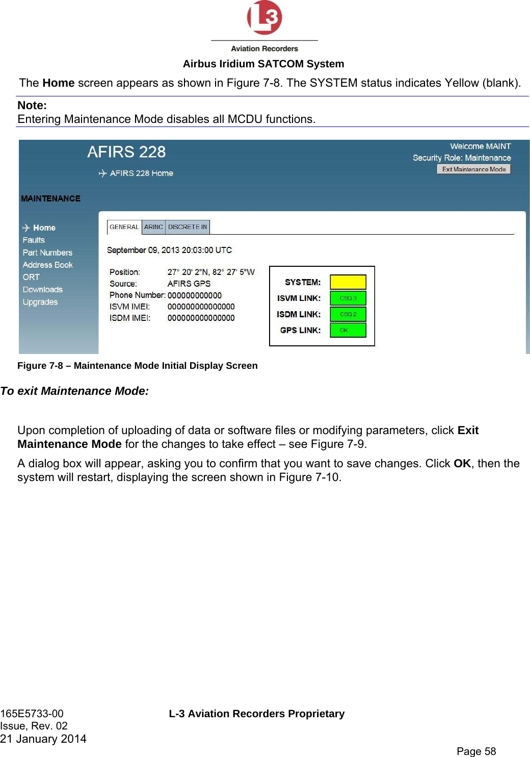
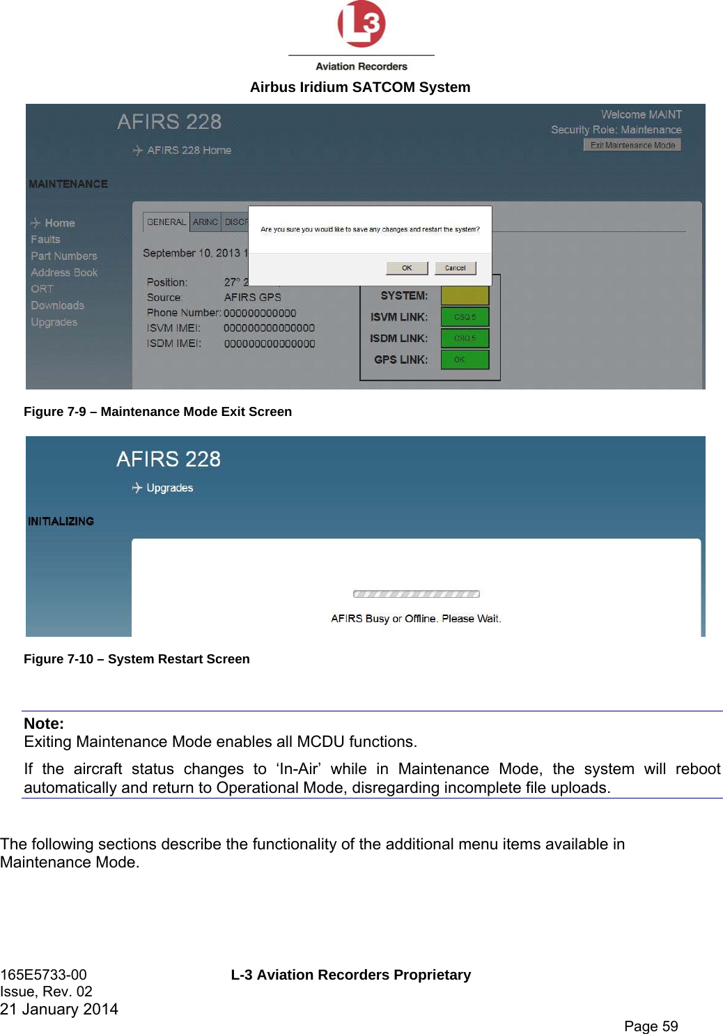
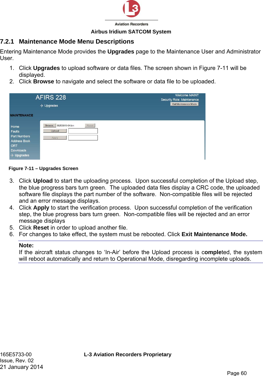
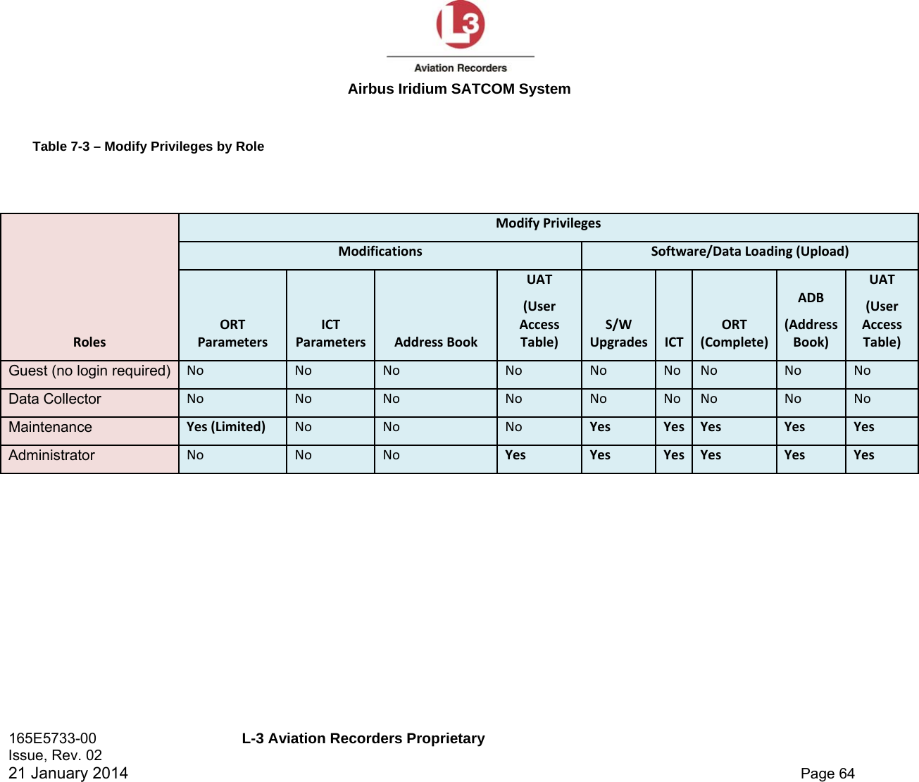
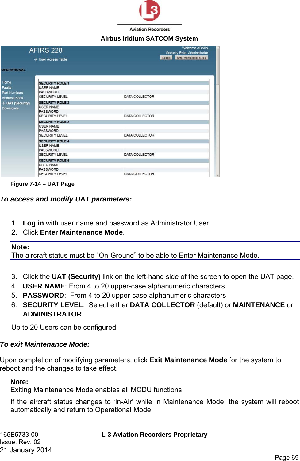
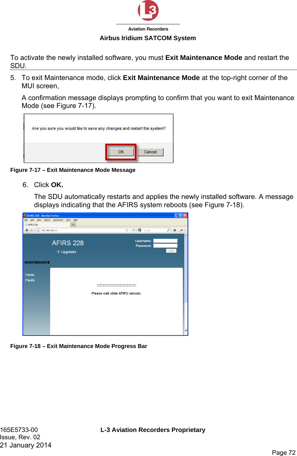
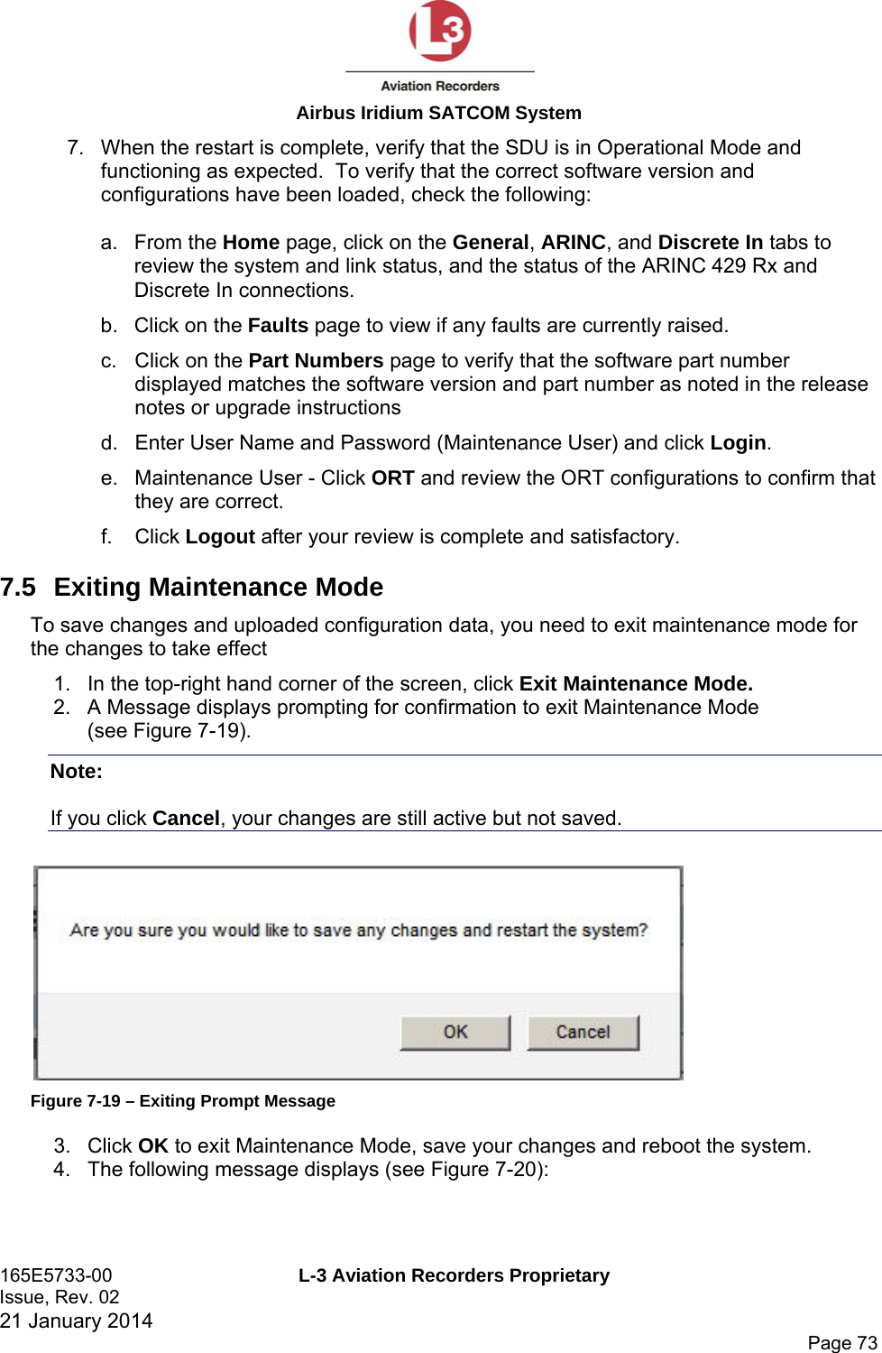
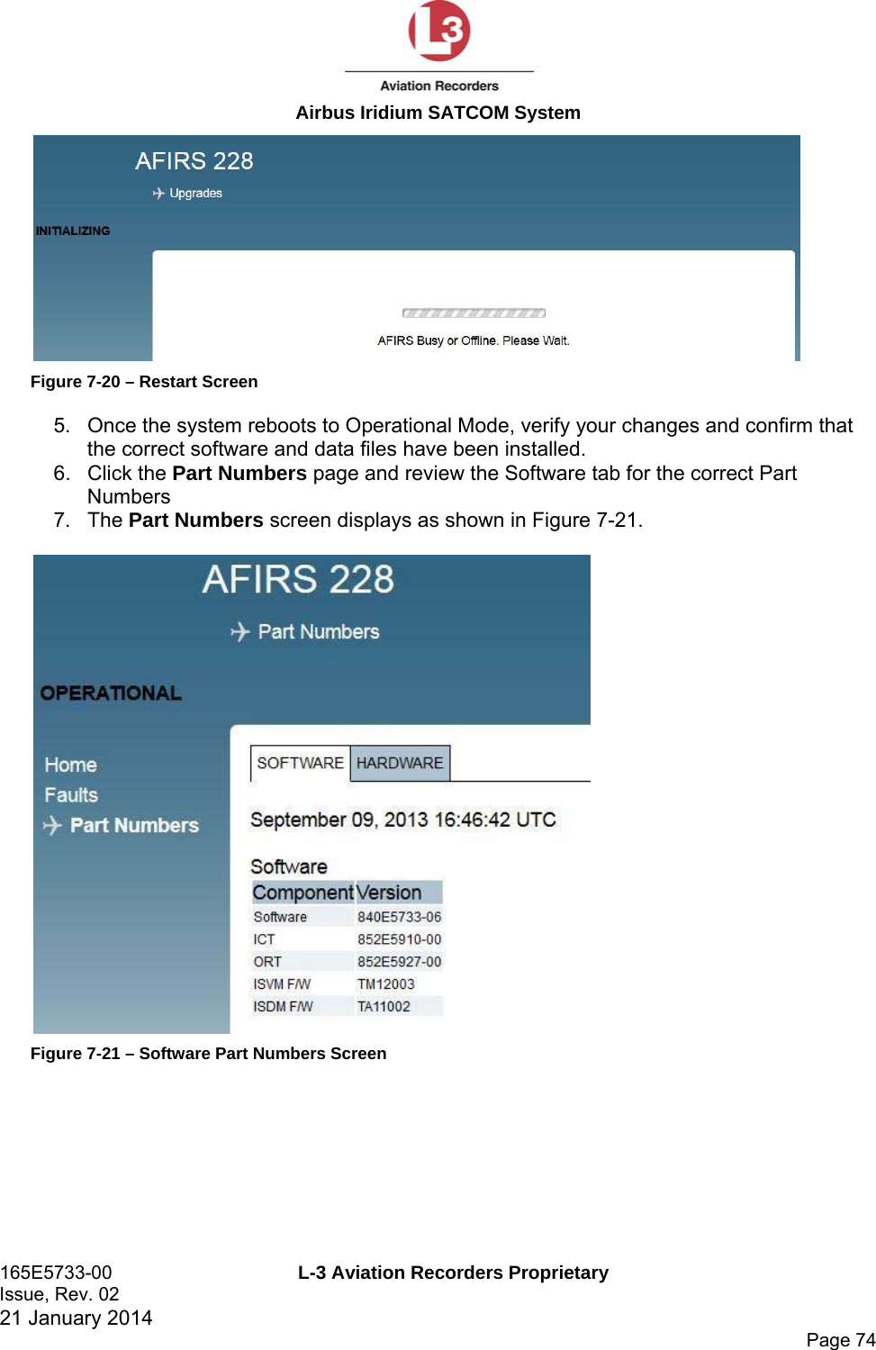
![Airbus Iridium SATCOM System 165E5733-00 L-3 Aviation Recorders Proprietary Issue, Rev. 02 21 January 2014 Page 57 7.2 Entering Maintenance Mode In order to enter Maintenance Mode, the aircraft must be deemed ‘On-Ground’. If the aircraft is deemed ‘In-Air’, the [Enter Maintenance Mode] button will be or will become unavailable. If the aircraft status changes to ‘In-Air’ while in Maintenance Mode, the system will reboot automatically and return to Operational Mode. Entering Maintenance Mode is granted to the following users after login with their assigned user name and password: Maintenance User Administrator User Entering Maintenance Mode provides the Upgrades page to the Maintenance User and Administrator User. In addition, the Maintenance User is allowed to modify 5 parameters in the ORT page. The Administrator User is allowed to modify parameters in the UAT page only. Role based MUI permissions are provided in Table 7-1 through Table 7-3 at the end of this section. To enter Maintenance Mode: 1. Once connected to the Airbus Iridium SATCOM System MUI, on the Home page, enter your user name and password, then click Login. 2. If the aircraft is deemed ‘On-Ground’, the [Enter Maintenance Mode] button is available at the top right corner of the screen. Click Enter Maintenance Mode. A message appears (see Figure 7-7) prompting for confirmation to enter Maintenance Mode. Figure 7-7– Entering Maintenance Mode Message 3. To enter Maintenance Mode, click OK.](https://usermanual.wiki/L3-Technologies/AFIRS228S0/User-Guide-3659344-Page-94.png)
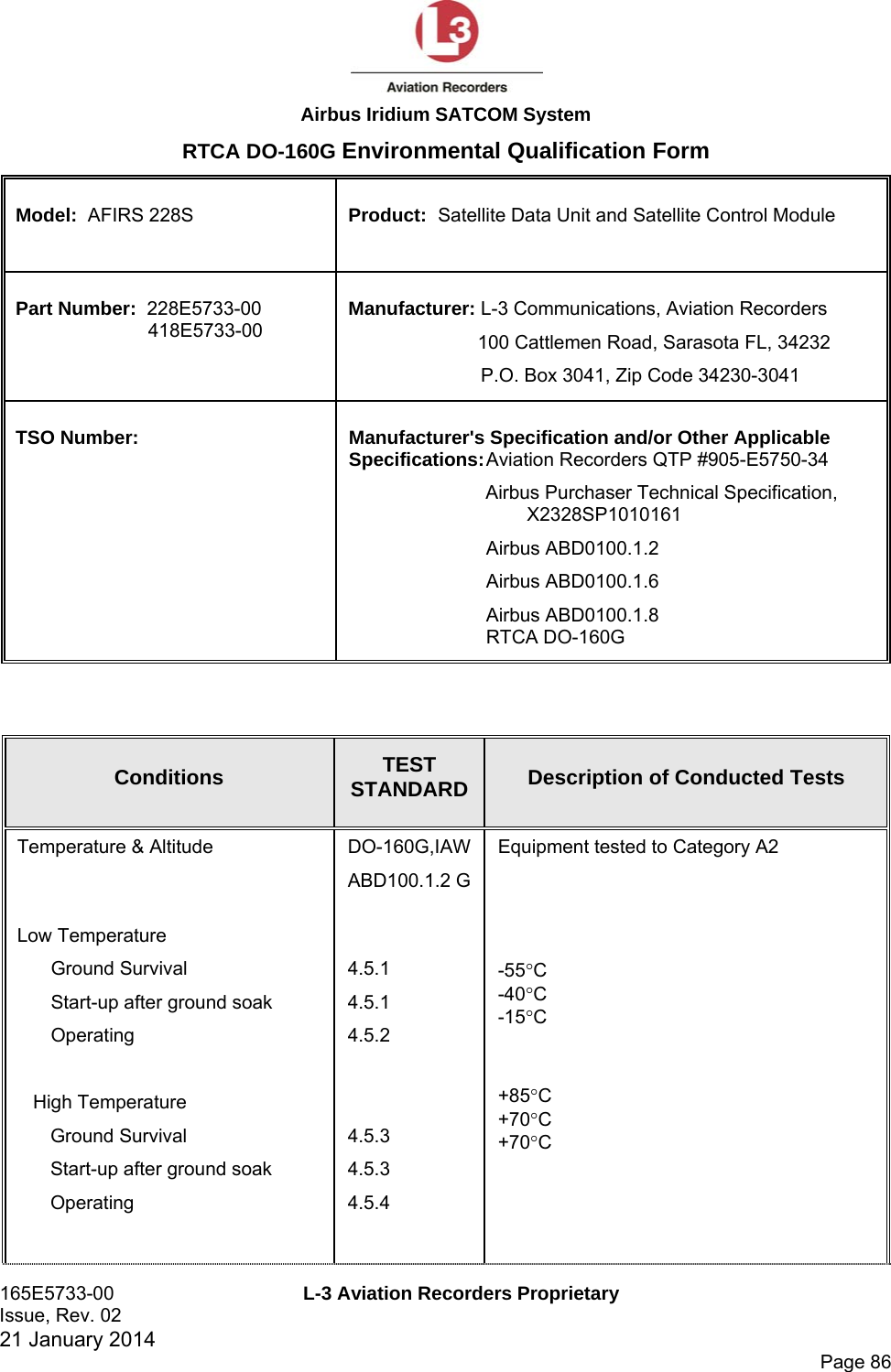
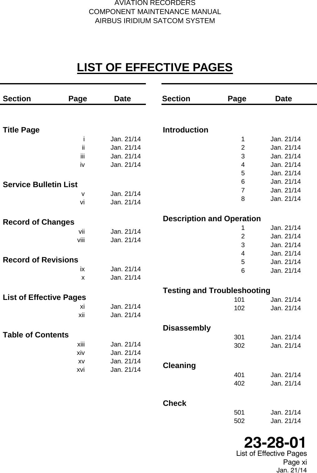
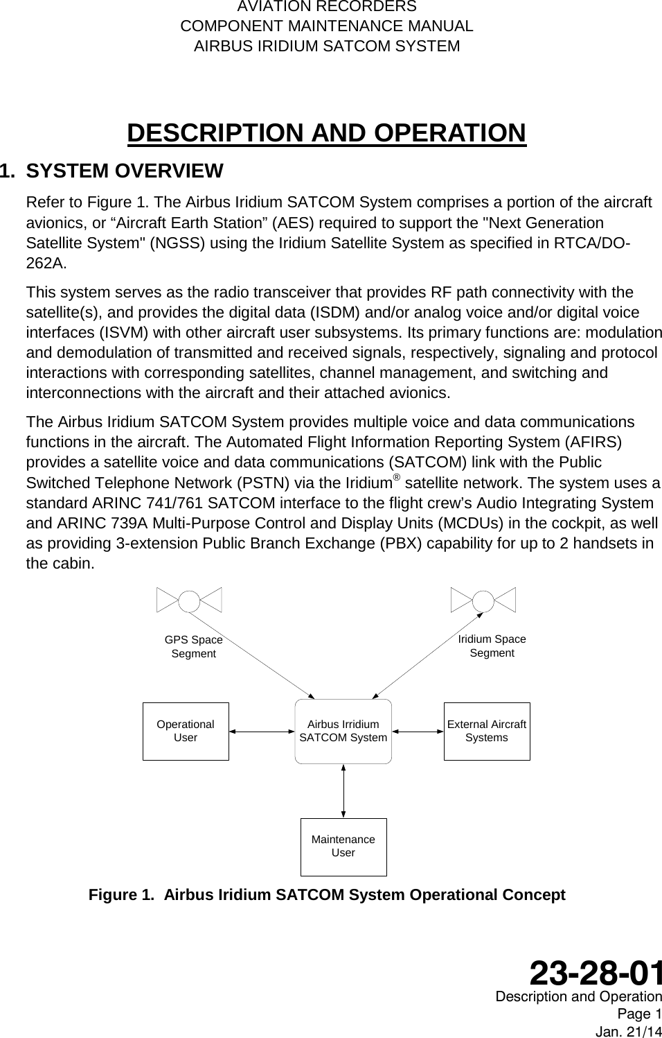
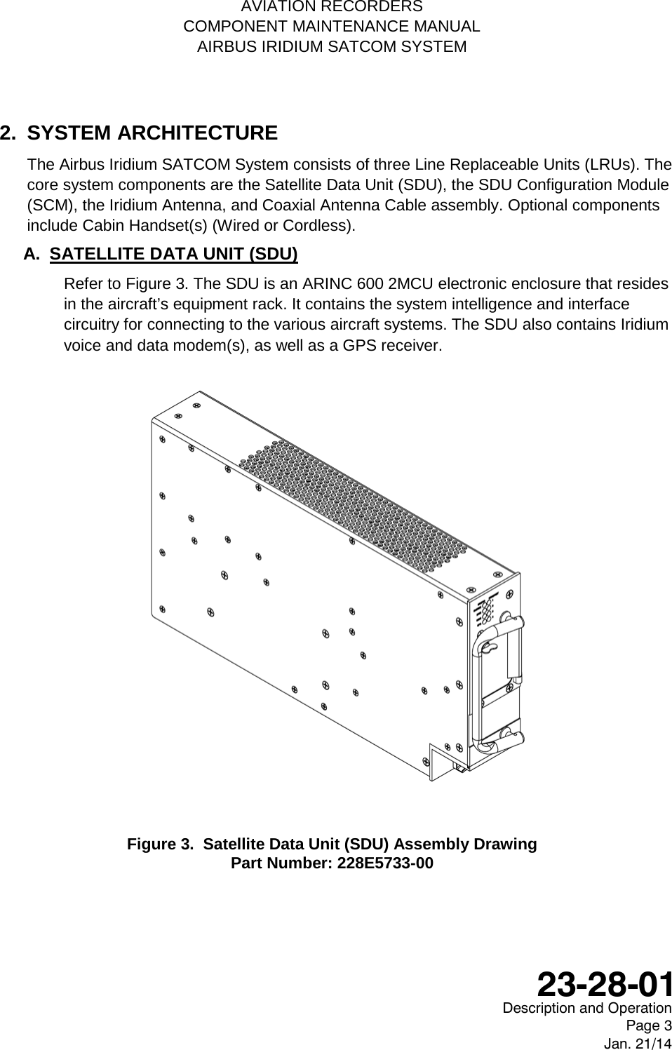

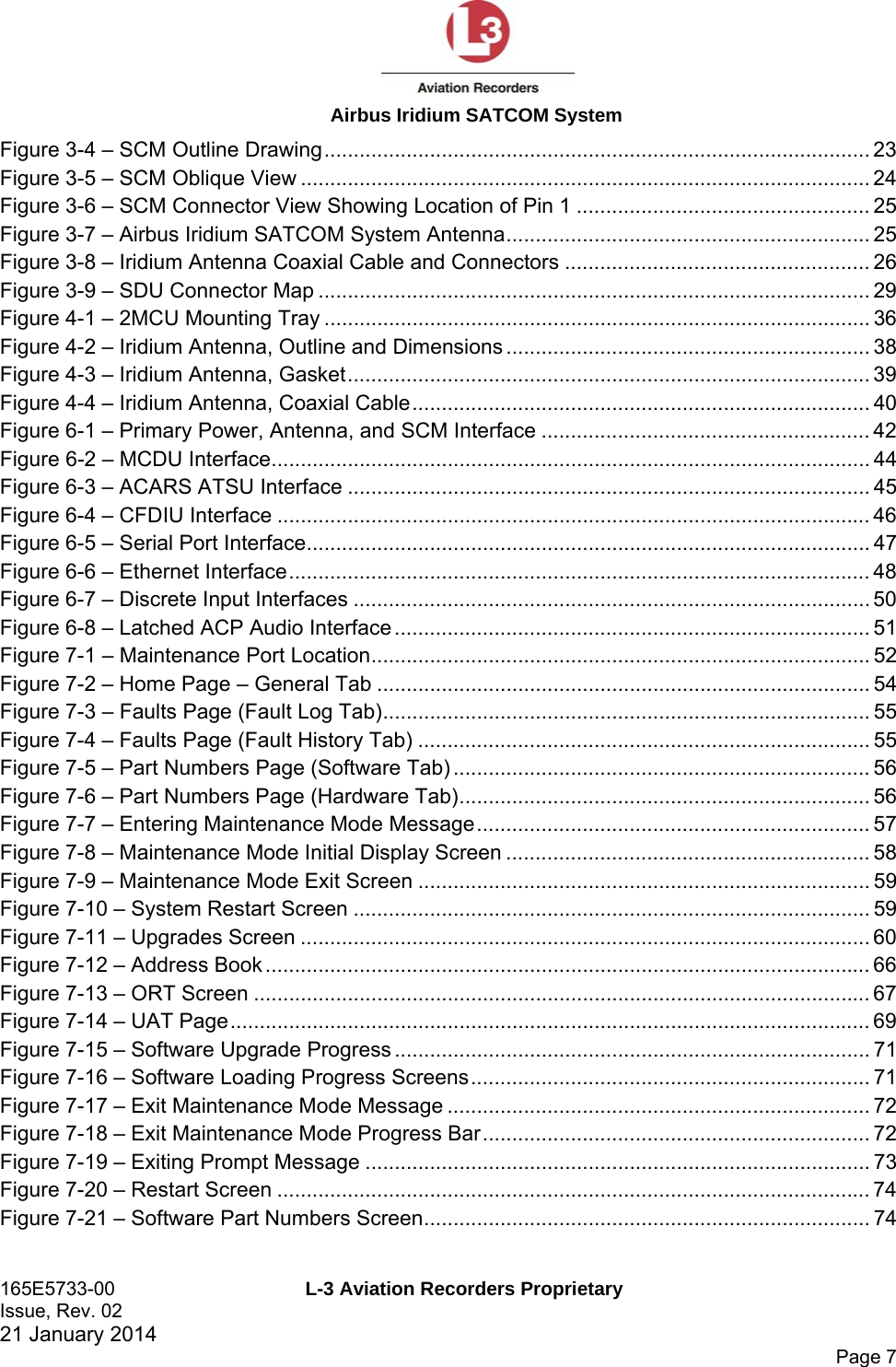
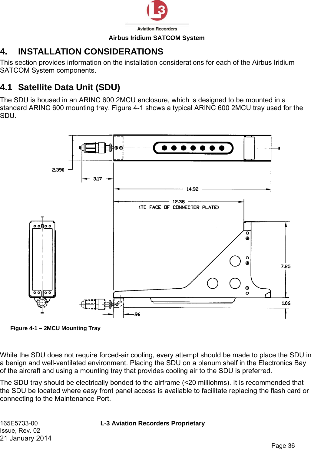
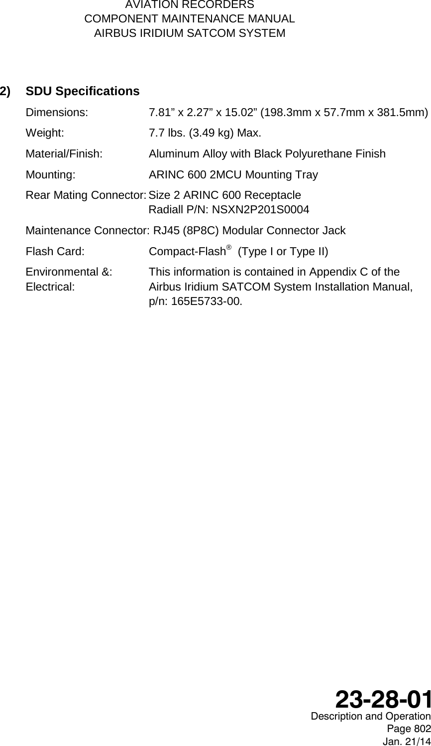
![AVIATION RECORDERS COMPONENT MAINTENANCE MANUAL AIRBUS IRIDIUM SATCOM SYSTEM FITS AND CLEARANCES 1. GENERAL This section provides the Airbus Iridium System specifications and outline and dimensions. Since the recorder uses solid-state memory recording technology, there are no internal fits and clearances or torque values normally associated with older technology electro-mechanical tape recorder units. 2. EQUIPMENT SPECIFICATIONS This section describes the mechanical specifications of the components of the Airbus Iridium SATCOM System. A. SATELLITE DATA UNIT (SDU) This paragraph describes the mechanical specifications of the Satellite Data Unit (SDU) refer to Figure 801 for an outline of this component. 1) SDU Outline & Dimensions The SDU is housed in an ARINC 600 2MCU enclosure, which is designed to be mounted in a standard ARINC 600 mounting tray. Figure 801. SDU Outline Drawing (dimensions in [millimeters] and inches) Description and Operation Page 801 Jan. 21/14 23-28-01](https://usermanual.wiki/L3-Technologies/AFIRS228S0/User-Guide-3659344-Page-170.png)
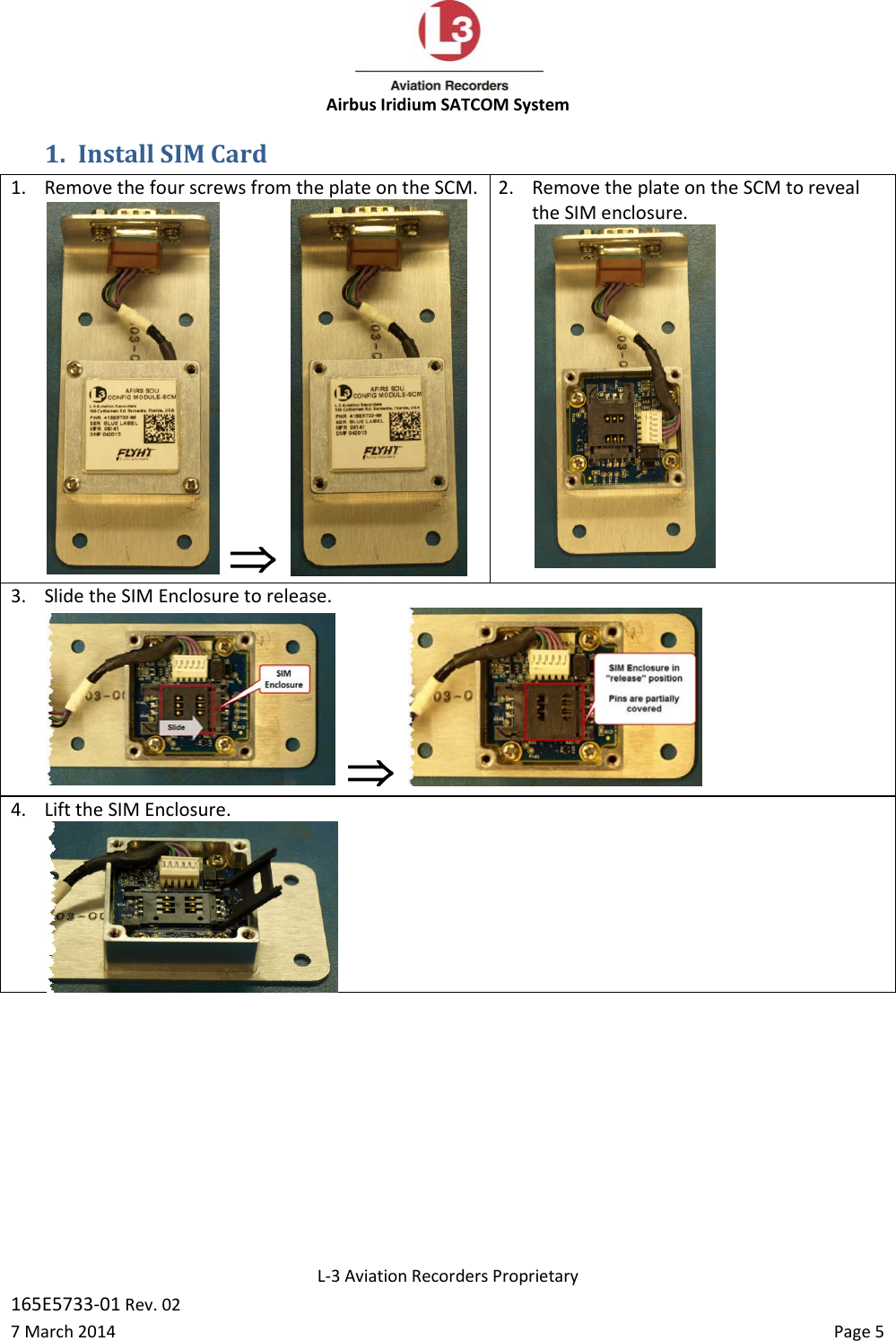
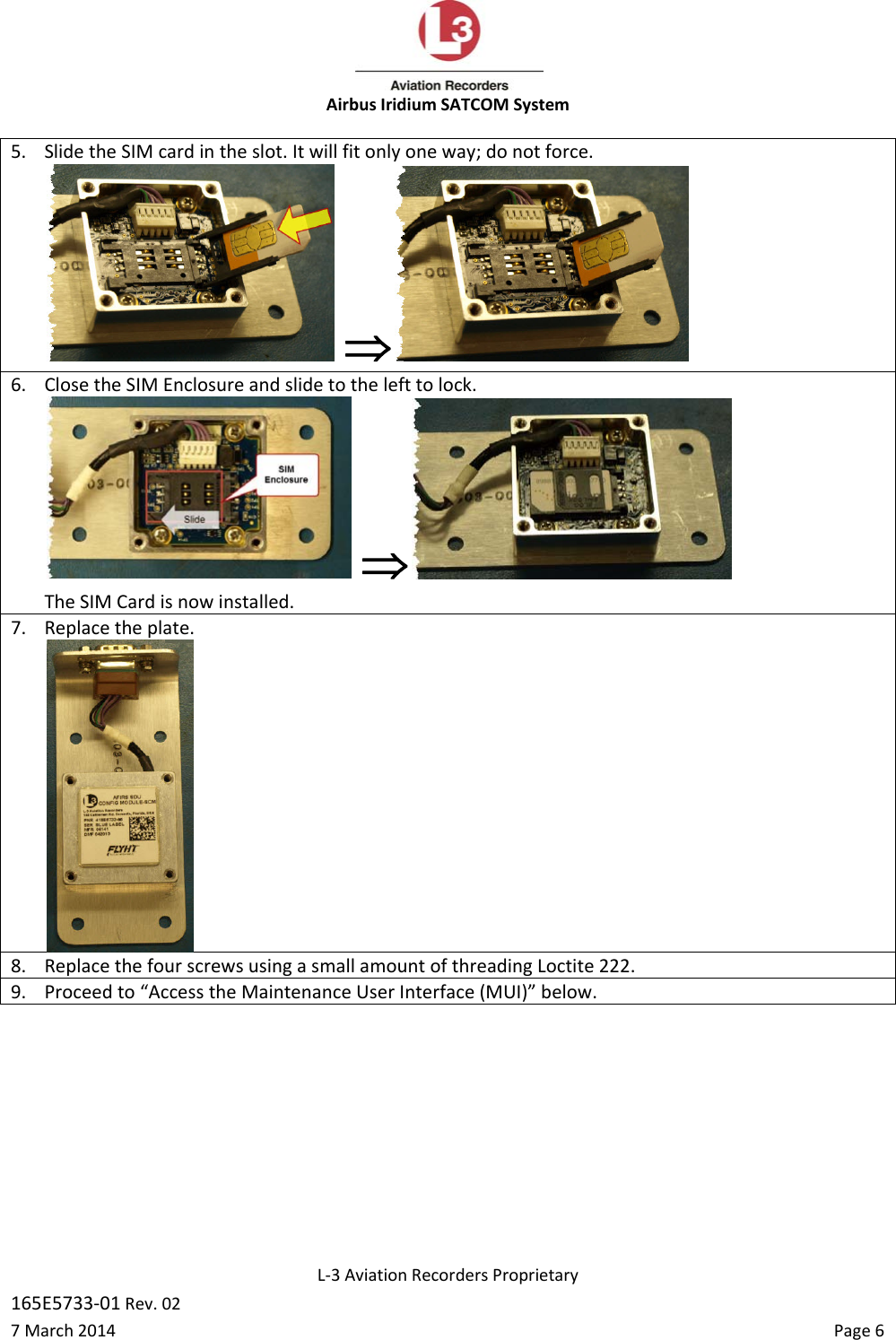
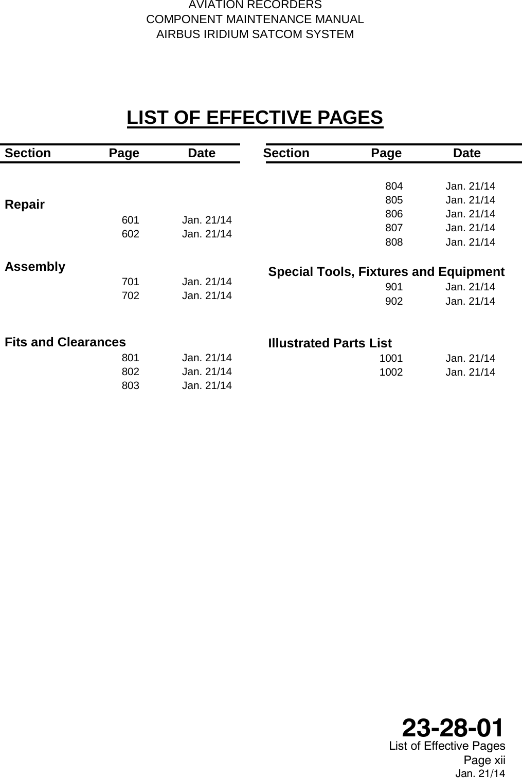
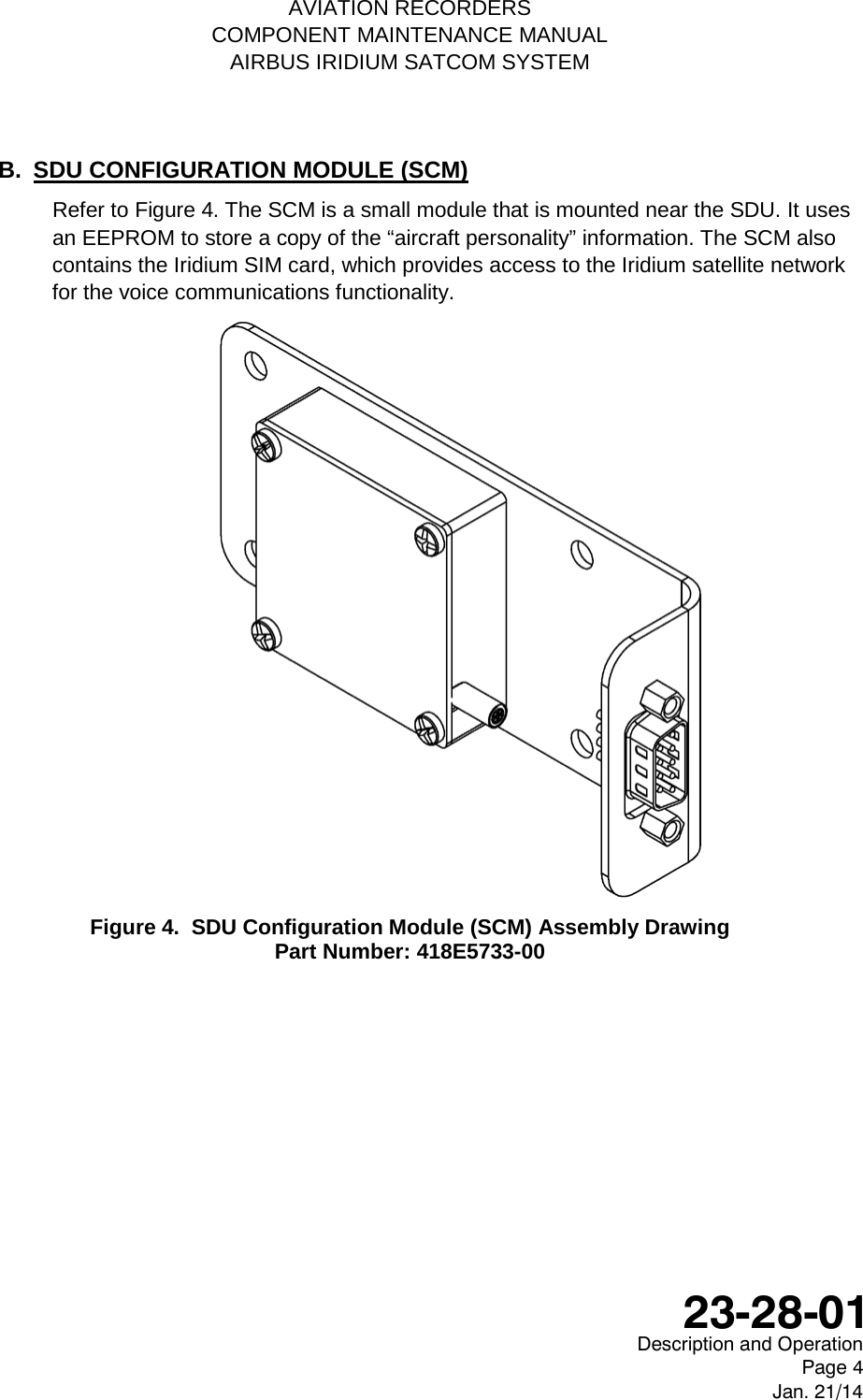
![AVIATION RECORDERS COMPONENT MAINTENANCE MANUAL AIRBUS IRIDIUM SATCOM SYSTEM B. SDU CONFIGURATION MODULE (SCM) This paragraph describes the mechanical specifications of the SDU Configuration Module (SCM). Refer to Figure 802 for an outline of this component. 1) SCM Outline & Dimensions Figure 802. SCM Outline Drawing (dimensions in [millimeters] and inches) 2) SCM Specifications Dimensions: 1.00” x 2.00” x 4.69” (25.4mm x 50.8mm x 119.1mm) Weight: 0.4 lbs. (0.18 kg) Max. Material/Finish: Aluminum alloy with clear chromate per MIL-DTL-5541, Type II, Class 3 on all surfaces. Environmental &: This information is contained in Appendix C of the Electrical: Airbus Iridium SATCOM System Installation Manual, p/n: 165E5733-00. Description and Operation Page 803 Jan. 21/14 23-28-01](https://usermanual.wiki/L3-Technologies/AFIRS228S0/User-Guide-3659344-Page-172.png)
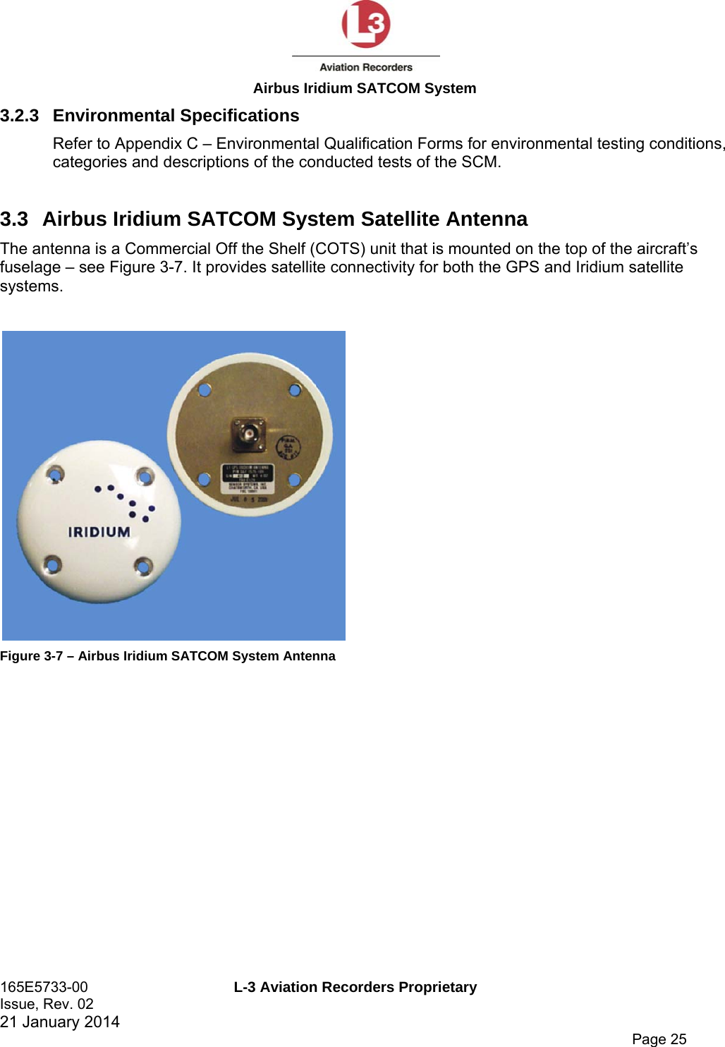
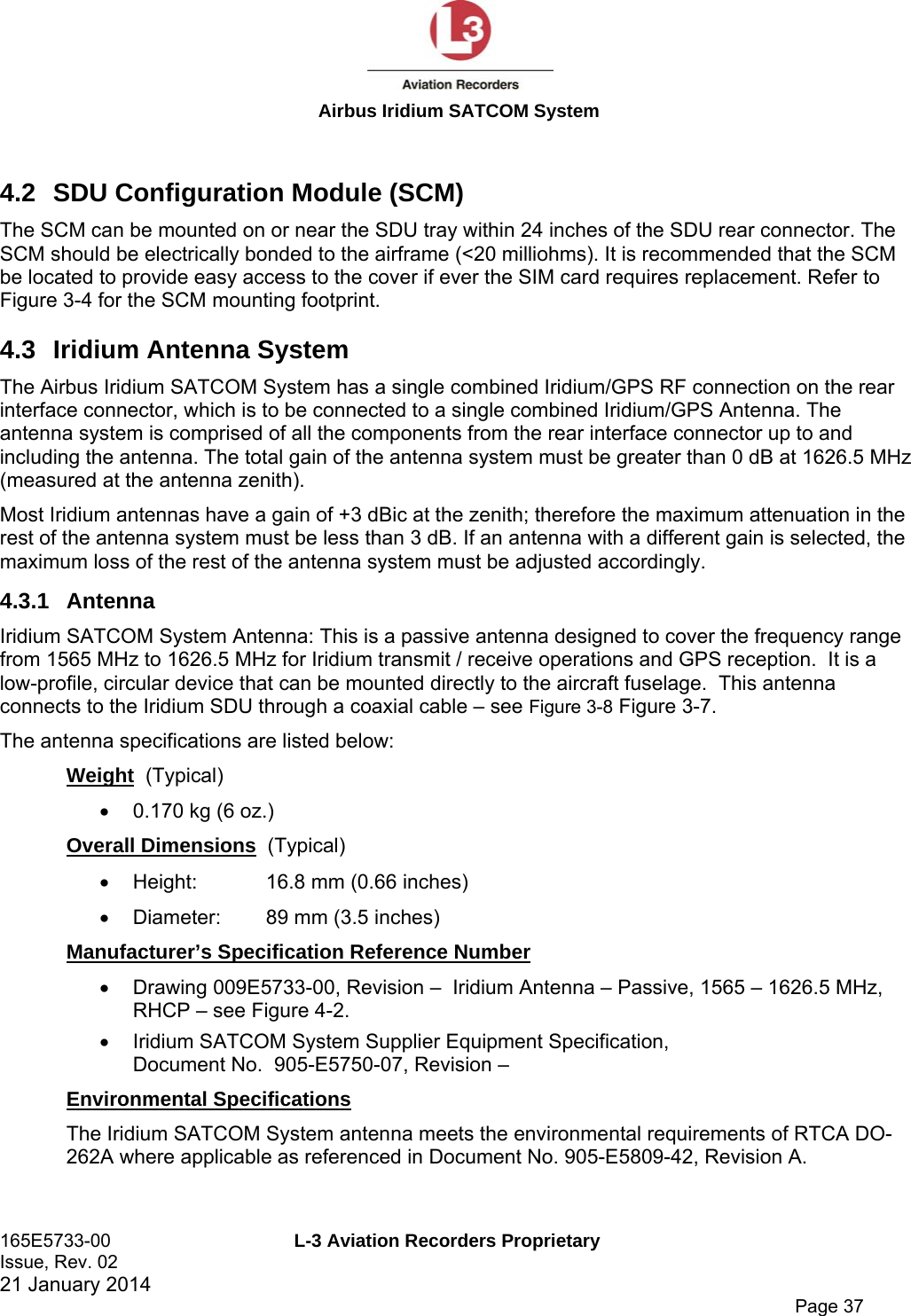
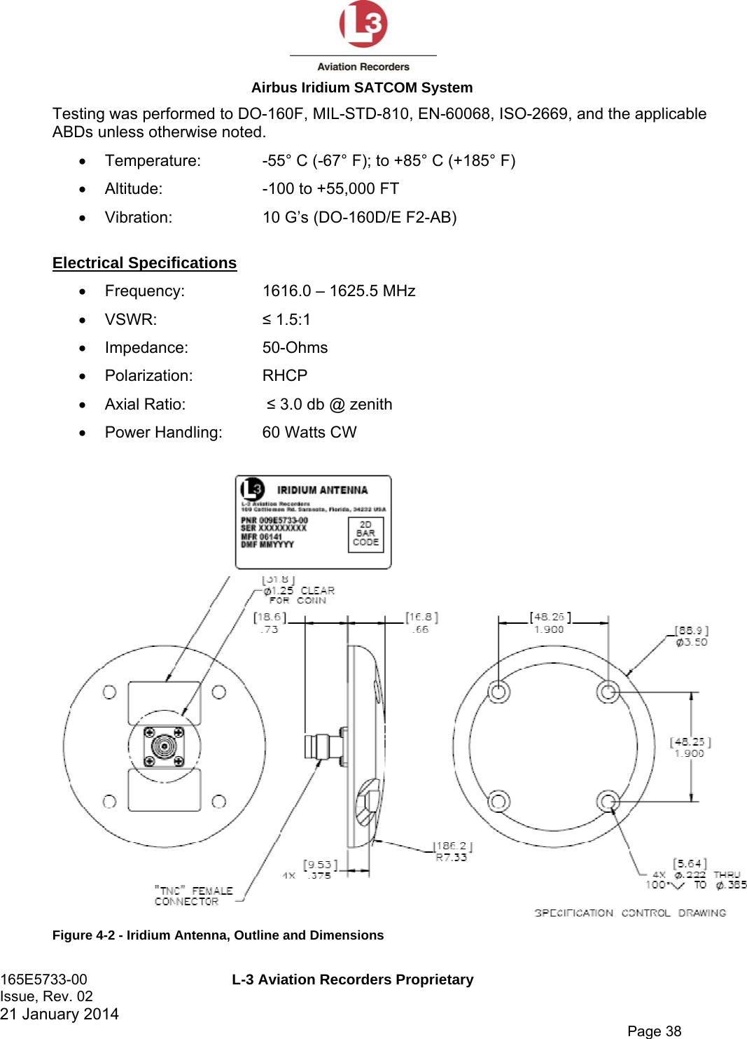
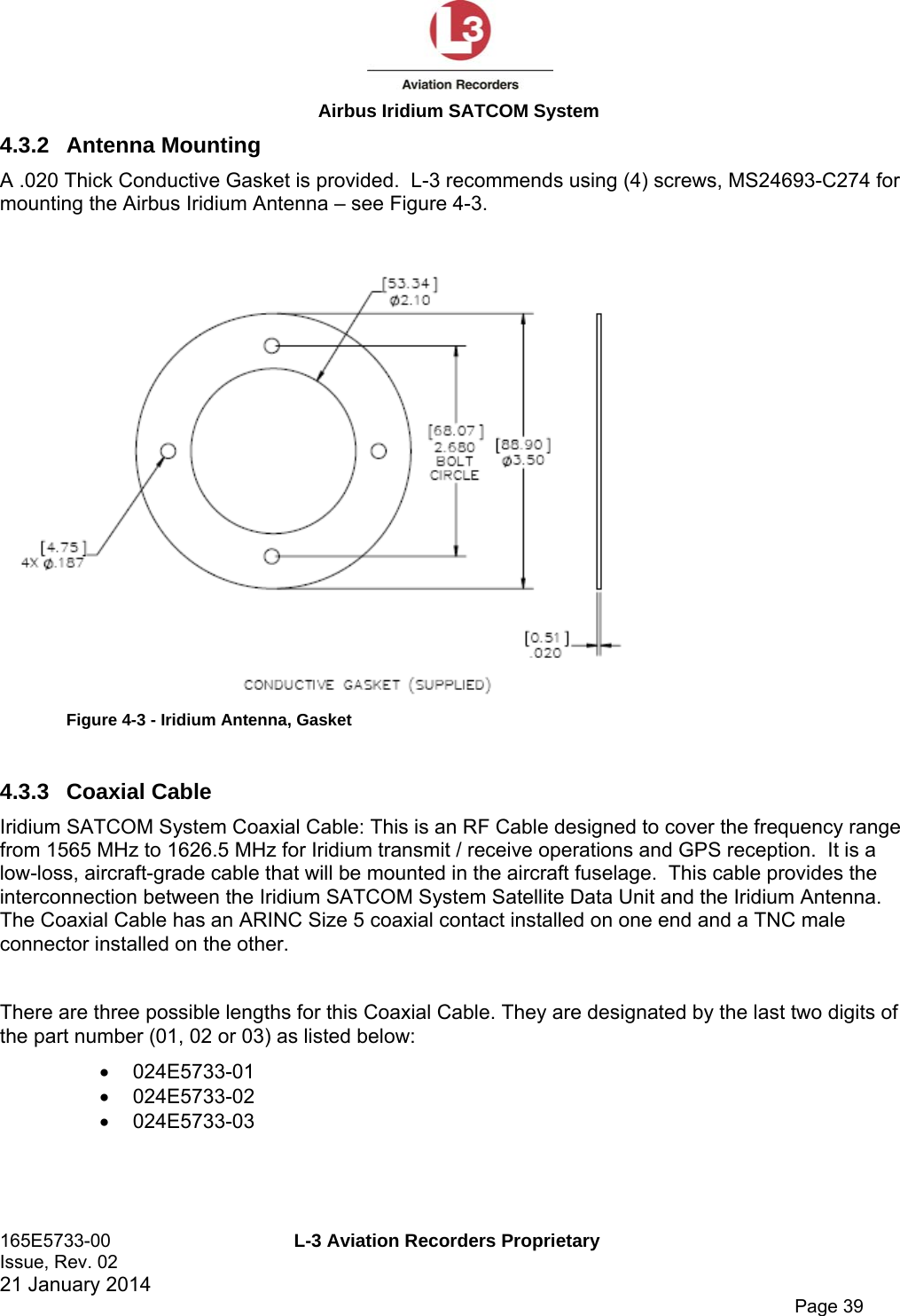
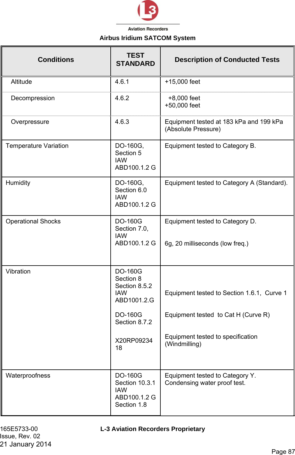
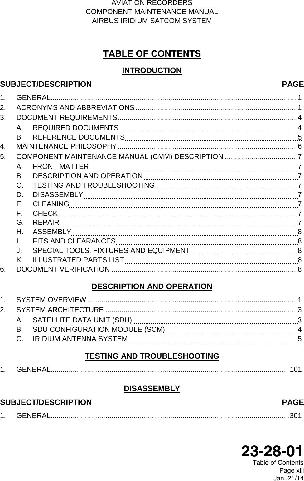
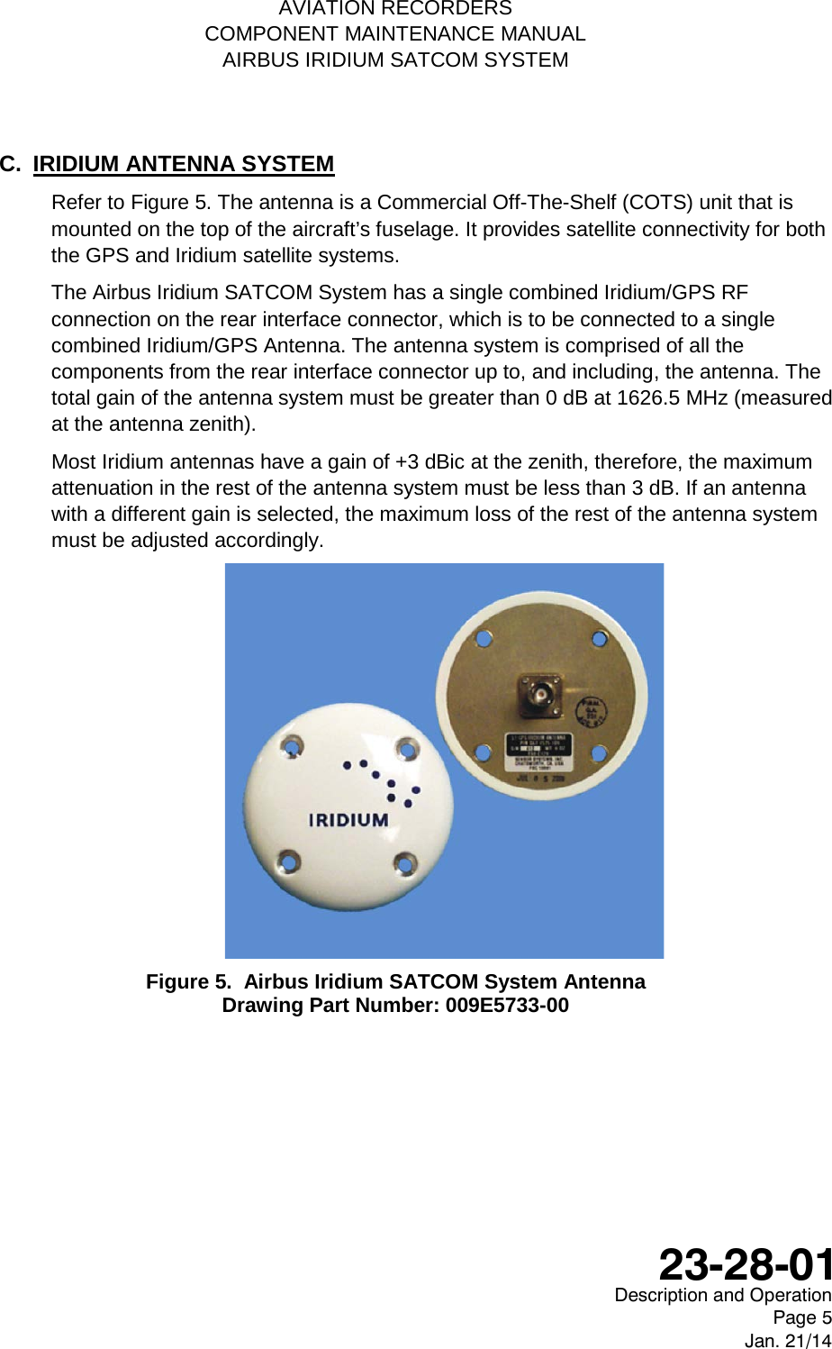
![AVIATION RECORDERS COMPONENT MAINTENANCE MANUAL AIRBUS IRIDIUM SATCOM SYSTEM C. IRIDIUM ANTENNA SYSTEM This paragraph describes the mechanical specifications of the Iridium Antenna. Refer to Figure 803 for the Outline & Dimension drawing of this component. 1) Iridium Antenna Outline & Dimensions Figure 803. Iridium Antenna Outline Drawing (dimensions in [millimeters] and inches) Description and Operation Page 804 Jan. 21/14 23-28-01](https://usermanual.wiki/L3-Technologies/AFIRS228S0/User-Guide-3659344-Page-173.png)

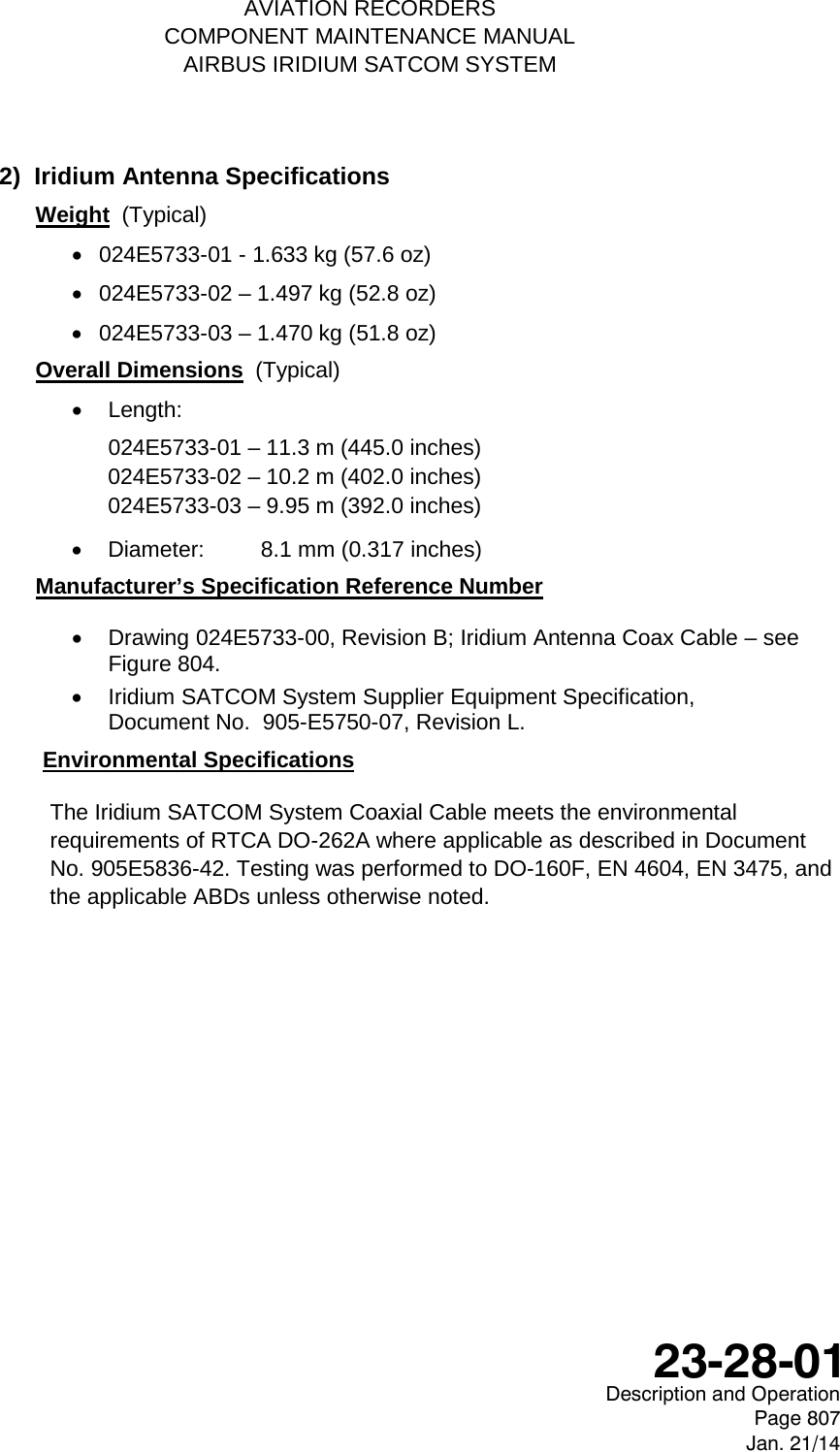
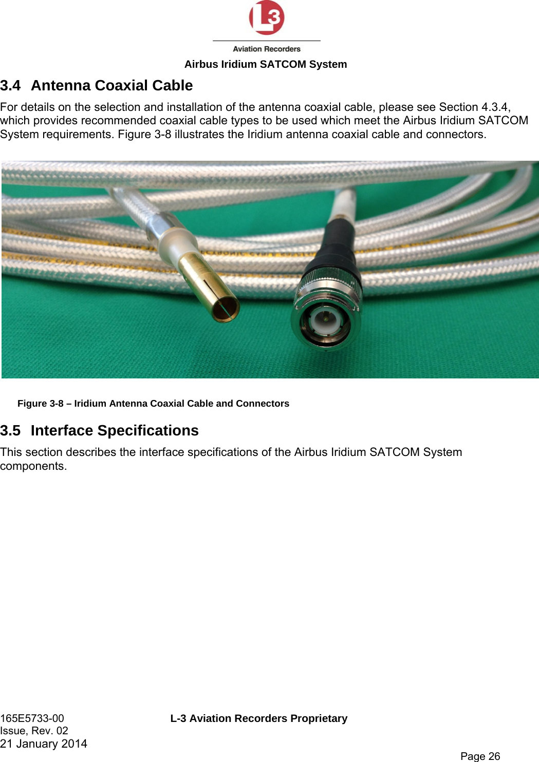
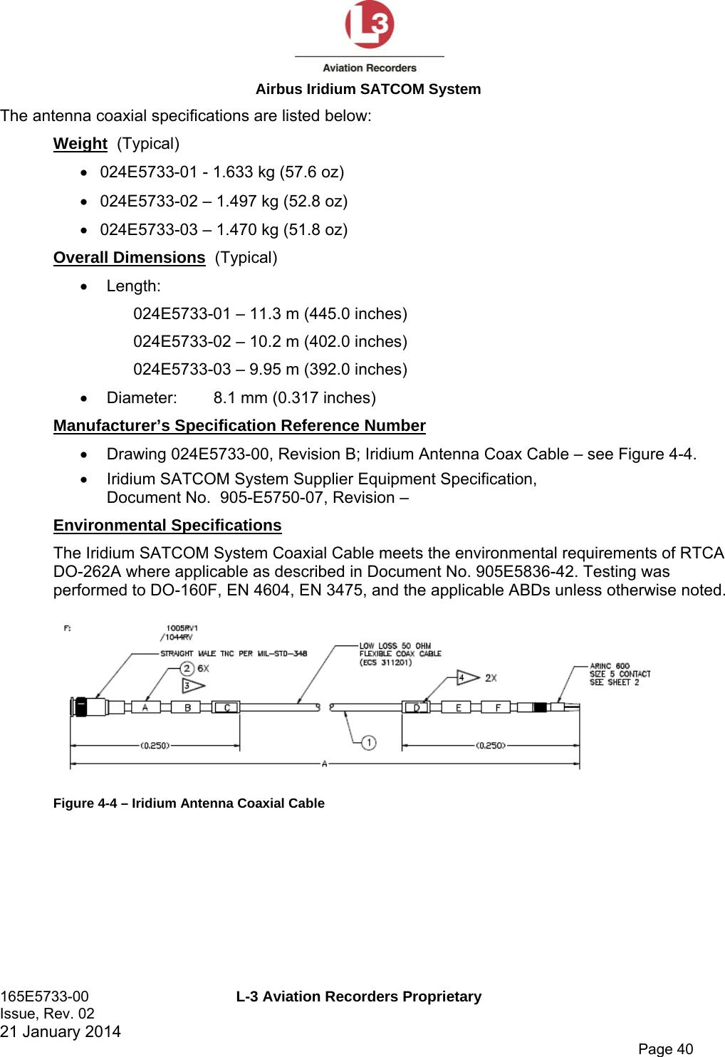
![AVIATION RECORDERS COMPONENT MAINTENANCE MANUAL AIRBUS IRIDIUM SATCOM SYSTEM Electrical Specifications Frequency: 1616.0 – 1625.5 MHz VSWR: ≤ 1.5:1 Impedance: 50-Ohms Polarization: RHCP • Axial Ratio: ≤ 3.0 db @ zenith • Power Handling: 60 Watts CW D. COAXIAL ANTENNA CABLE ASSEMBLY Refer to Figure 804. The Iridium SATCOM System Coaxial Cable is an RF Cable designed to cover the frequency range from 1565 MHz to 1626.5 MHz for Iridium transmit / receive operations and GPS reception. It is a low-loss, aircraft-grade cable that will be mounted in the aircraft fuselage. This cable provides the interconnection between the Iridium SATCOM System Satellite Data Unit and the Iridium Antenna. The Coaxial Cable has an ARINC Size 5 coaxial contact installed on one end and a TNC male connector installed on the other. There are three possible lengths for this Coaxial Cable. They are designated by the last two digits of the part number (01, 02 or 03) as listed below: 1) Coaxial Antenna Outline & Dimensions Figure 804. Coaxial Antenna Cable Outline Drawing (dimensions in [millimeters] and inches) Description and Operation Page 806 Jan. 21/14 23-28-01](https://usermanual.wiki/L3-Technologies/AFIRS228S0/User-Guide-3659344-Page-175.png)