L3 Technologies AFIRS228S0 AFIRS 228S Satellite Data Unit User Manual Iridium SATCOM System Welcome Package
L3 Technologies AFIRS 228S Satellite Data Unit Iridium SATCOM System Welcome Package
User Manual
IridiumIridium ®®
Welcome Welcome
PackagePackage
PackagePackage
Airbus Iridium SATCOM System

100 Cattlemen Road, Sarasota, Florida 34232
Telephone: 941-371-0811 Facsimile: 941-377-5591
Confidential Page1
Welcome!
Dear Valued Customer,
All of us at L-3 Aviation Recorders take this opportunity to say “thank you” for your selection of the L-3
Airbus Iridium Satellite Communication (SATCOM) system.
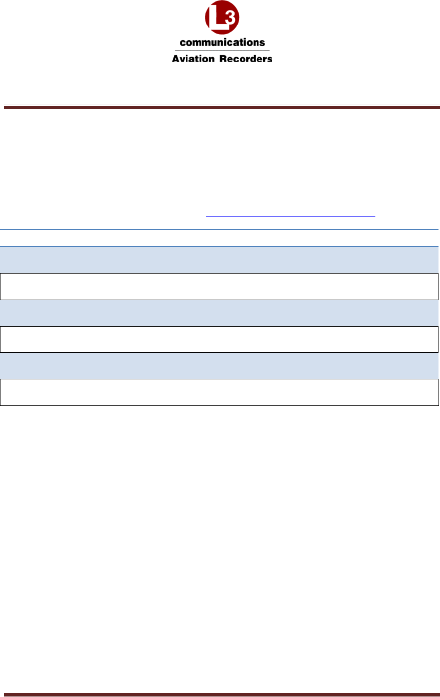
This SATCOM system, also identified as the Automated Flight Information & Reporting System (AFIRS),
is a multi-function voice and data communication system that provides a link between the aircraft and
ground using the existing Iridium satellite constellation. The system consists of:
Satellite Data Unit (SDU)
SDU Configuration Module (SCM), which houses the system SIM card
Iridium Antenna
Coaxial Cable
These system elements are described in further detail in the following sections of this Welcome Kit
package. The system performs the following primary functions:
Satellite Phone
The Iridium SATCOM System contains a single-channel Iridium satellite phone along with an internal
Private Branch Exchange (PBX) system. The AFIRS 228 SDU includes telecom functions integrated into
the cockpit audio system for the flight crew and separate calling capability through conventional two-wire
“tip and ring” telephony devices. Cockpit dialing and control functions can be performed by using the
aircraft's Multipurpose Control Display Units (MCDUs). Up to two wired or eight cordless handsets can be
added in the cabin for intercom, call transfer, conference calling, camp-on calling and noise-cancelling
features. The aircraft can call or be called from any conventional telephone, as well as any other similarly-
equipped aircraft. This provides the crew with worldwide access to MedLink or other emergency medical
services.
ACARS Satellite Data Unit
For ACARS-equipped aircraft, the Iridium SATCOM System can function as a standard ARINC
741/761 Satellite Data Unit (SDU) when interfaced to the aircraft's ACARS Communication Management
Unit (CMU). The system uses a dedicated Iridium satellite channel for data services. The Iridium SATCOM
System receives messages from the CMU, prioritizes the messages, and transmits them over the Iridium
satellite link. ACARS messages received from the satellite link are routed to the CMU for processing.

100 Cattlemen Road, Sarasota, Florida 34232
Telephone: 941-371-0811 Facsimile: 941-377-5591
Confidential Page2
Electronic Flight Bag (EFB) Interface
If desired, the Iridium SATCOM System SDU provides an EFB with an interface to the EFB message
transport system. An Ethernet port provides the physical connection between the devices – using industry
standard IEEE 802.3 LAN technologies. Once physically connected, the SDU routes to the EFB a web-
based portal that can be accessed by EFB applications using a defined IP based protocol, supporting text
messaging and other functions.
L-3 Aviation Recorders manufactures and services the Iridium SATCOM system. To learn more about L-3
products, please visit the company’s website at: http://www.l-3ar.com/ .
This Welcome Package includes the following useful information for you to obtain support for effective
operation of your Iridium SATCOM system:
L-3 Contact Information
Authorized Service Facility Information
Compliance Package (Export Compliance Certification, End-Use/User Statement)
Technical Documentation (Quick Guide, and Installation & Operation Manual)
Customer Training Schedule
CD – includes all Welcome Package documentation & a Component Maintenance Manual
Thank you again for your interest in our products. We look forward to working with you to bring your new
Airbus Iridium SATCOM System on-line in your fleet operations, and to meeting your needs and
expectations in the support and service of your Airbus Iridium SATCOM System.
Mike Phillips
Product Support Manager
L-3 Aviation Recorders
100 Cattlemen Road, Sarasota, Florida 34232
Telephone: 941-371-0811 Facsimile: 941-377-5591
Confidential Page1
Table of Contents
This Welcome Package includes the documents listed in the table below.
Keep in mind, these documents may not be the latest up-to-date revisions. Please check the L-3 Customer
Support website for the latest update available at: http://www.l-3ar.com/customer/index.htm
Documents
Welcome Letter
L-3 Contact Details
Airbus Iridium SATCOM System Quick Start Guide
Iridium SIM Card Registration
Installation Manual Airbus Iridium SATCOM System
Airbus Iridium SATCOM System Component Maintenance Manual

S t Fl id 34232
S
araso
t
a,
Fl
or
id
a
34232
CAGE Code 06141
Phone: (941) 371–0811 | FAX: (941) 377–5591
http://www.l-3ar.com/
I
ridium Customer
Su
pp
or
t
I
ridium Customer
Su
pp
or
t
Technicalsupport,Reliability,Productsupport
DaveDowding
SeniorProductSupportEngineer
Phone941.377.5551
Cell 941 284 3048
DarenWelker
ProductSupportEngineer
Phone941.379.1620
Cell 941 372 2313
CarloMammelli
PublicationsSupervisor
Phone941.377.5550
Cell 941 726 9050
pppp
Cell
941
.
284
.
3048
Fax941.377.5591
Emaildavid.dowding@l‐3com.com
Cell
941
.
372
.
2313
Fax941.377.5591
Emaildaren.welker@l‐3com.com
Cell
941
.
726
.
9050
Fax941.377.5591
Emailcharles.mammelli@l‐3com.com
Technical Technical
Mike Phillips
DocumentationDocumentation
ForaccesstoTechnicaldocumentation,pleaselogonto:
Website:http://www.l‐3ar.com/customer/technical.htm
Forspecificrequestsontechnicaldocumentation,contact:
Email:charles.mammelli@l‐3com.com
Mike
Phillips
ProductSupportManager
Phone941.377.5547
Cell941.726.0107
Fax941.377.5591
Emailmike.phillips@l‐3com.com
Customer Iridium Operator training is provided
TrainingTraining
Formoredetailsconcernin
g
L3ARTrainin
g
p
leaseusethislink:
Customer
Iridium
Operator
training
is
provided
three(3)timesayearattheL3ARFacilityin
Sarasota,FL.
2014TrainingDates
Feb.18‐20,2014
Jun. 23‐25,2014
Oct.20‐22,2014
g g p
Website:http://www.l‐3ar.com/services/training_aviation.htm
Forquestionsaboutproducttraining,contact:
Email:daren.welker@l‐3com.com

Sarasota
,
Florida 34232
Authorized Service Facilit
y
Authorized Service Facilit
y
,
CAGE Code 06141
Phone: (941) 371–0811 | FAX: (941) 377–5591
http://www.l-3ar.com/
yy
AEuropeanservicefacilitywillbeestablishedlaterin2014.Untilsuch
time,allIridiumrepairswillbeperformedatL‐3Factory.
Address:
L‐3CommunicationsAviationRecorders
100CattlemenRd.Sarasota,Florida34232
Attention: Repair Station
941
377
5517
Attention:
Repair
Station
–
941
‐
377
‐
5517
RepairStationManager:GeraldGodbee
Phone:941.377.5531Email:gerald.godbee@l‐3com.com

AirbusIridiumSATCOMSystem
L‐3AviationRecordersProprietary
165E5733‐01Rev.02
7March2014Page1
AirbusIridiumSATCOMSystem
QuickStartGuide
SDU L-3 part number 228E5733-00
SCM L-3 part number 418E5733-00
AirbusIridiumSATCOMSystem
L‐3AviationRecordersProprietary
165E5733‐01Rev.02
7March2014Page2
SECTION1‐OVERVIEW
1. AirbusIridiumSATCOMSystemOverview
TheAirbusIridiumSATCOMSystemwillbecertifiedtoTSOC‐159aforvoiceanddatasafety‐services.It
hasadual‐channelIridiumlink,onededicatedfordata‐withthecapabilitytosendandreceivestandard
ACARSmessagesbetweentheaircraft’sAirTrafficServiceUnit(ATSU),andtheotherprioritizedfor
voiceviaacertifiedterrestrialserviceprovider.
TheAutomatedFlightInformationReportingSystem(AFIRS)providesasatellitevoiceanddata
communications(SATCOM)linkwiththePublicSwitchedTelephoneNetwork(PSTN)viatheIridium®
satellitenetwork.ThesystemusesastandardARINC741/761SATCOMinterfacetotheflightcrew’s
AudioIntegratingSystemandARINC739AMulti‐PurposeControlandDisplayUnits(MCDUs)inthe
cockpit,aswellasproviding3‐extensionPublicBranchExchange(PBX)capabilityforupto2handsetsin
thecabin.
AirbusIridiumSATCOMSystem
L‐3AviationRecordersProprietary
165E5733‐01Rev.02
7March2014Page3
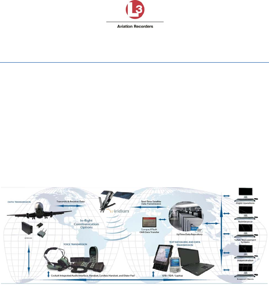
SatelliteDataUnit(SDU)
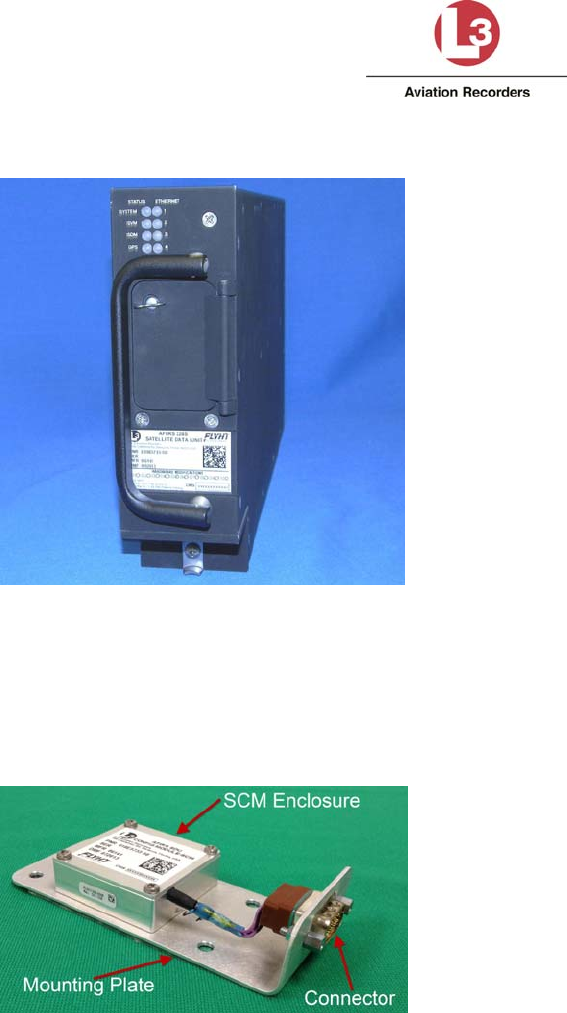
2. SDUConfigurationModule(SCM)
TheSCMishousedinasmallenclosure,whichisdesignedtobemountedwithin24”oftheSDUrear
connector.TheSCMandantennaconnectdirectlytotheSDU.TheSDUistheheartofthesystemand
providesalloftheinterfacestootheraircraftsystems.
AirbusIridiumSATCOMSystem
L‐3AviationRecordersProprietary
165E5733‐01Rev.02
7March2014Page4
SECTION2–SYSTEMCONFIGURATION
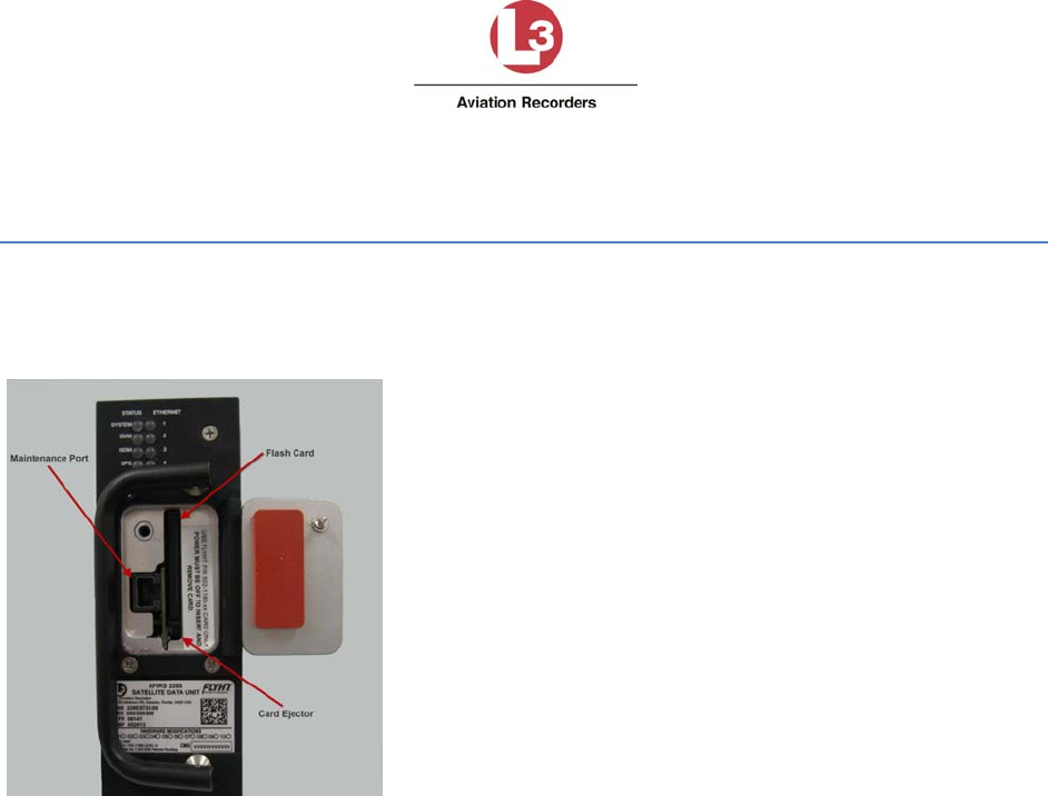
YouconfiguretheAirbusIridiumSATCOMSystemSatelliteDataUnit(SDU)viaEthernetusingalaptop,
webbrowser,andtheAFIRSMaintenanceUserInterface(MUI).AnRJ‐45MaintenancePortjackis
locatedbehindtheaccessdooronthefrontpaneloftheSDU.
IMPORTANT:READBEFORECONFIGURINGSATCOMSYSTEM
TheMUIonlyacceptsEnglish‐languagecharactersandnumbers.
Theaircraft’sstatusmustbedeemed“On‐Ground”toaccessMaintenanceModeandmakeany
systemchanges.Iftheaircraftisdeemed“In‐Air”,theEnterMaintenanceModebuttonwillbe,
orwillbecome,unavailable.Iftheaircraftstatuschangesto“In‐Air”whileinMaintenance
Mode,thesystemwillrebootautomaticallyandreturntoOperationalModewithoutsavingany
changes.
EnteringMaintenanceModedisablesallMCDUfunctions.
AirbusIridiumSATCOMSystem
L‐3AviationRecordersProprietary
165E5733‐01Rev.02
7March2014Page5
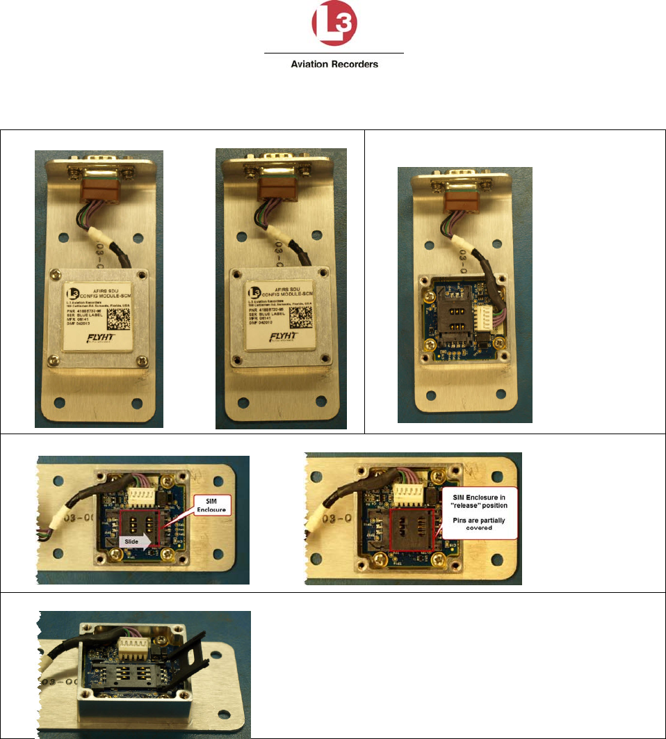
1. InstallSIMCard
1. RemovethefourscrewsfromtheplateontheSCM.
2. RemovetheplateontheSCMtoreveal
theSIMenclosure.
3. SlidetheSIMEnclosuretorelease.
4. LifttheSIMEnclosure.
AirbusIridiumSATCOMSystem
L‐3AviationRecordersProprietary
165E5733‐01Rev.02
7March2014Page6
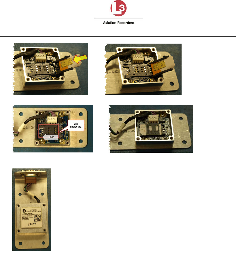
5. SlidetheSIMcardintheslot.Itwillfitonlyoneway;donotforce.
6. ClosetheSIMEnclosureandslidetothelefttolock.
TheSIMCardisnowinstalled.
7. Replacetheplate.
8. ReplacethefourscrewsusingasmallamountofthreadingLoctite222.
9. Proceedto“AccesstheMaintenanceUserInterface(MUI)”below.
AirbusIridiumSATCOMSystem
L‐3AviationRecordersProprietary
165E5733‐01Rev.02
7March2014Page7
3. AccesstheMaintenanceUserInterface(MUI)
1. Withsystempoweron,connectanEthernetcabletotheMaintenancePortviathefront
panelaccessdooroftheSDU.
2. Connecttheotherendofthecabletoalaptopwithawebbrowser(MozillaFireFox®is
recommended).
3. Confirmthatthegreenlinklightisilluminated.Thelightcanbesteadyorflashing–flashing
meansthatdataisbeingtransmitted.
4. Setthelaptopnetworkadaptertothefollowing:
IP=192.168.128.10
SubnetMask=255.255.255.0
Note:TheMaintenanceportcanauto‐negotiatethebestspeed(10/100)andmode(full/halfduplex).
5. Openthelaptop’swebbrowserandclearthecache.
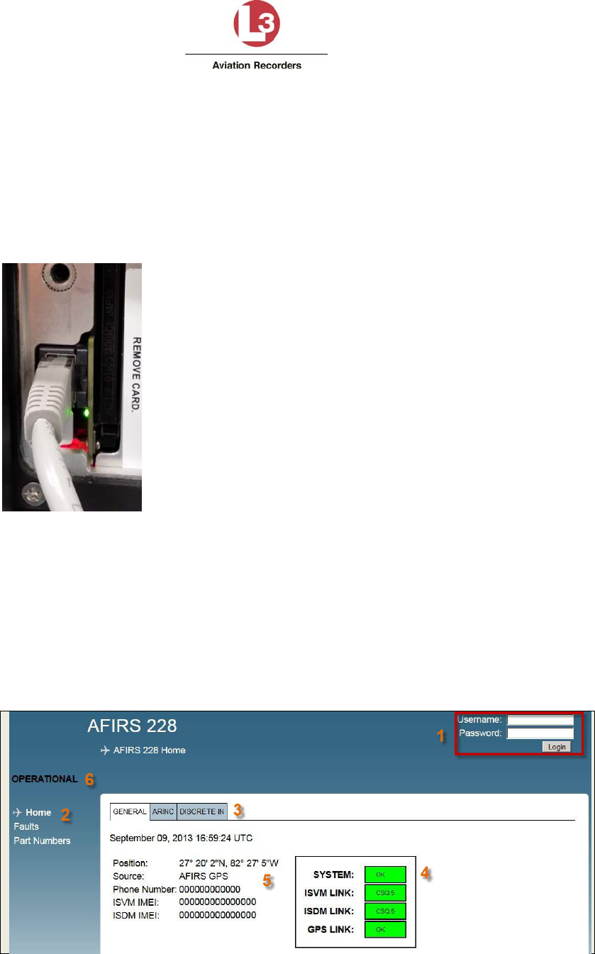
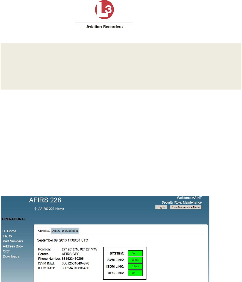
6. IntheAddressbar,typethefollowingdefaultIPaddress:192.168.128.1.TheAirbusIridium
SATCOMSystemHomepagewilldisplaywiththeGeneraltabinformationdisplayed.
AirbusIridiumSATCOMSystem
L‐3AviationRecordersProprietary
165E5733‐01Rev.02
7March2014Page8
1‐Loginarea
2‐Menuofavailablelinkstopagesaccessibletovarioususersuponlogin
3‐Tabs:GENERAL,ARINC,andDISCRETEIN
4‐SystemandLinkstatusdisplayarea
5‐Systeminformationdatadisplayarea
6‐Mode:OPERATIONAL,MAINTENANCE,INITIALIZING,etc.
7. Proceedto“AccessMaintenanceMode”below.
4. AccessMaintenanceMode–OnGroundStatusRequired
1. YouarenowconnectedtotheAirbusIridiumSATCOMSystemMUIHomePage;typethe
followingintheLoginfields:
DefaultUserName:AFIRSMAINT
DefaultPassword:228MAINT
2. ClickLogin.
3. ClickEnterMaintenanceMode.Amessagedisplays,promptingforconfirmationtoenter
MaintenanceMode.
4. ClickOK.TheMUI–MaintenanceHomePagewilldisplay.
5. ModifyOwnerRequirementsTable(ORT)Parameters
1. YouareloggedintotheMUIasaMaintenanceUserfromthepreviousprocess.Youwillnow
beabletocustomizeparametersfortheindividualaircraftoperatorbasedonoperational
requirementsorpreferences.
2. ClickEnterMaintenanceMode.Aconfirmationmessagedisplays.
3. ClickOK.
AirbusIridiumSATCOMSystem
L‐3AviationRecordersProprietary
165E5733‐01Rev.02
7March2014Page9
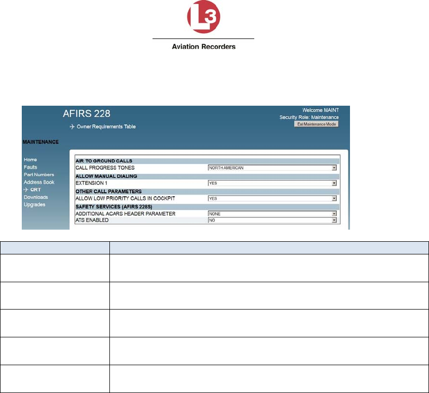
4. ClicktheORTlinkontheleftsideofthescreentoopentheORTpage.TheOwner
RequirementsTablewilldisplay.
Fiel
d
AvailableOptions
CallProgressTonesNorthAmerican
European
Extension1Yes–Callsfromcockpitcanbeplacedmanually
No–Callsfromcockpitcanonlybeplacedfromaddressbook
LowPriorityCallsYes–Lowprioritycallscanbereceived/madefromcockpit
No–Lowprioritycallscannotbereceived/madefromcockpit
AdditionalACARS
Header
None–SITAService
ARINC–ARINCService
AirTrafficService(ATS)Yes–SIMcardwithATS
No–SIMcardwithoutATS
6. CreateanAddressBook
1. ClickDownloadsfromtheleftmenu.
2. ChoosetheAddressBookoption.
3. ClickDownload.
4. ChoosetheSaveFileoption.
AirbusIridiumSATCOMSystem
L‐3AviationRecordersProprietary
165E5733‐01
Rev.02
7March2014Page10
5. ClickOK.
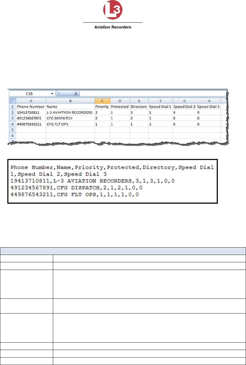
AnAddressBooktemplatewilldownloadtothecomputerasacomma‐separated‐valuesfile
(adb.csv).IfthecomputerdoesnothaveMicrosoftExcel®,thefilecanbeopenedasa
MicrosoftWordPad®file.
ExampleofMicrosoftExcel®AddressBookfile.
ExampleofMicrosoftWordPad®AddressBookfile.
6. Locateandopentheadb.csvfile.
7. Addentriestotheaddressbook(upto300)andmodifyasnecessary.
Therearenolistnumbersintheadb.csvfiletoidentifyindividualentries.
Important:Thetemplate(adb.csv)entriesmustadheretotheparametersexactly.
AddressBookParameters
PhoneNumber Upto18digits (Alwaysincludecountrycode)
NameUpto23upper‐casealpha‐numericcharacters(A‐Z,0‐9,+,‐,/,space)
Priority
UseonlyATS‐
enabledIridium
SIMcards.
4–Public
3–Non‐Safety
2–Safety
1–Emergency
Protected0–No
1–Yes
Directory4–Public
3–Non‐Safety
2–Safety
1–Emergency
SpeedDial11
SpeedDial20(notcurrentlyused)
SpeedDial30(notcurrentlyused)
8. WhenfinishedmodifyingtheAddressBook,saveandclosethefile.
Important:Thefilenamemustremainadb.csvorthefilewillnotload.
9. ClickUpgradesfromtheleftmenu.
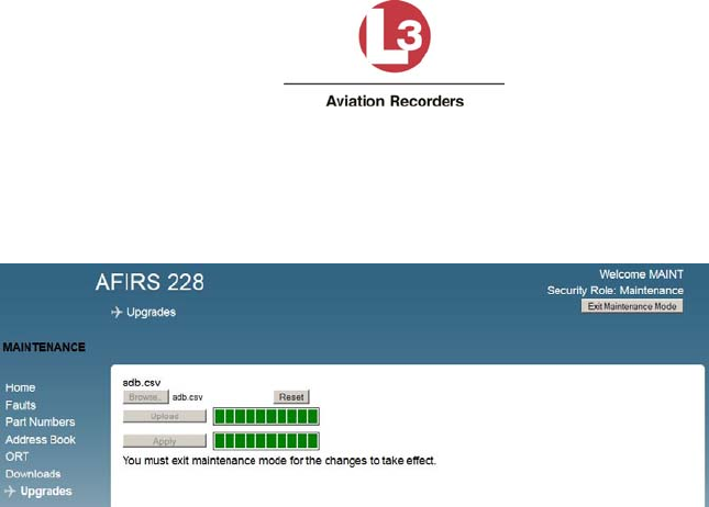
AirbusIridiumSATCOMSystem
L‐3AviationRecordersProprietary
165E5733‐01Rev.02
7March2014Page11
10. ClickBrowseandlocatetheadb.csvfilethatyoujustcreated.
11. ClickUpload.
12. ClickApply.
13. ClickExitMaintenanceModewhenupdatesarecomplete.Amessagedisplays,prompting
forconfirmationtoexitMaintenanceMode.
14. ClickOK.Thesystemsaveschanges,reboots,andreturnstoOperationalMode.
15. Proceedto“EnterAdministratorRole”below.
7. EnterAdministratorRole‐On‐GroundStatusRequired
1. YouarestillconnectedtotheAirbusIridiumSATCOMSystemMUIHomePage;typethe
followingintheLoginfields:
DefaultUserName:AFIRSADMIN
DefaultPassword:ADMIN228
2. ClickLogin.
3. ClickEnterMaintenanceMode.
AirbusIridiumSATCOMSystem
L‐3AviationRecordersProprietary
165E5733‐01Rev.02
7March2014Page12
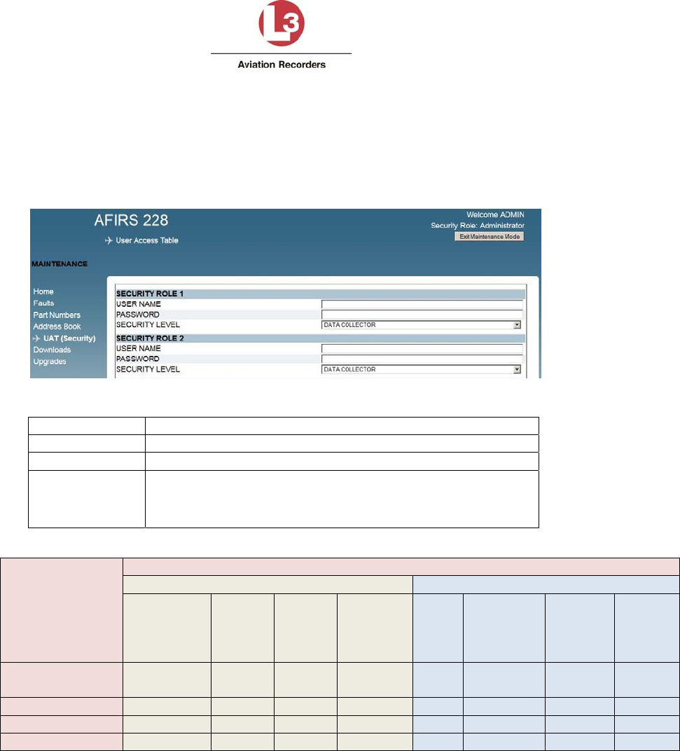
8. UpdateUserAccessTable(UAT)Parameters
TheUserAccessTable(UAT)isusedtosetupuseraccessprivilegesforupto20users.These
settingsmaybechangedasneededtomeetoperationalrequirements.
1. ClicktheUAT(Security)linkontheleftsideofthescreentoopentheUATpage.
2. Addsecurityrolesasnecessarybasedonthefollowingparameters.
FieldParameter
UserName4‐20upper‐casealpha‐numericcharacters
Password4‐20upper‐casealpha‐numericcharacters
SecurityLevelDataCollector(default)
Maintenance
Administrator
Roles
Privileges
Modifications Software/DataLoading(Upload)
ORT
Parameters
Address
Book
UAT
(User
Access
Table)
S/W
UpgradesICT
ORT
(Complete)
ADB
(Address
Book)
UAT
(User
Access
Table)
Guest
(nologinrequired)NoNoNoNoNoNoNoNo
DataCollectorNoNo No No No NoNo No
MaintenanceYesNo No Yes Yes YesYes Yes
AdministratorNoNo Yes Yes Yes YesYes Yes
Note:Alluserscandownloadfaultlogs,exceptGuest.
3. Whenfinished,clickExitMaintenanceModeforthesystemtorebootandsavechanges.
4. Proceedto“Section3‐Testing”or“DownloadBackupUATFile(Optional)”below.

AirbusIridiumSATCOMSystem
L‐3AviationRecordersProprietary
165E5733‐01Rev.02
7March2014Page13
a. DownloadBackupUATFile(Optional)
YoumaywanttodownloadabackupUATfilethatyoucoulduploadintheeventthat
thesystemfileshouldfail.
1. OntheHomePage,typethefollowingintheLoginfields:
DefaultUserName:AFIRSADMIN
DefaultPassword:ADMIN228
2. ClickLogin.
3. ClickDownloads.
4. SelecttheUAToptionfromtheConfigurationssection.
5. ClickDownload.
6. ChooseSave.
7. ClickOK.
8. Proceedto“Section3‐Testing”below.
AirbusIridiumSATCOMSystem
L‐3AviationRecordersProprietary
165E5733‐01Rev.02
7March2014Page14
SECTION3–TESTING
1. TestSystemVoiceConnectivity
Performthefollowingstepstoensurethatthesystemisworkingproperly.Ifyoudonothave
voicetransmissionavailable,proceedtoTestSystemDataConnectivity.Forinformationon
Built‐inTestsandFaultIndicators,seetheInstallationandOperationsManual.
a. CallfromLandlinePhonetoIridiumSATCOMPhone
NON‐ATS(AirTrafficService)SIM
1. CallIridiumCallService
U.S.1‐480‐768‐2500
Non‐U.S.001‐480‐768‐2500
2. EnterIridium12digitphonenumberandfollowwiththe#symbol.
ATS(AirTrafficService)SIM
1. CallIridiumCallService
U.S.1‐480‐730‐3900
Non‐U.S.001‐480‐730‐3900
2. EnterIridium12digitphonenumberandfollowwiththe#symbol.
3. Enterthefollowinginformationwhenpromptedandfolloweachentrywiththe
#symbol.ThisinformationisprovidedbySIMcardprovider.
UserID
PIN
Prioritylevel
o Emergency
o Safety
o Non‐Safety
o Public
PlaneID
AirbusIridiumSATCOMSystem
L‐3AviationRecordersProprietary
165E5733‐01Rev.02
7March2014Page15
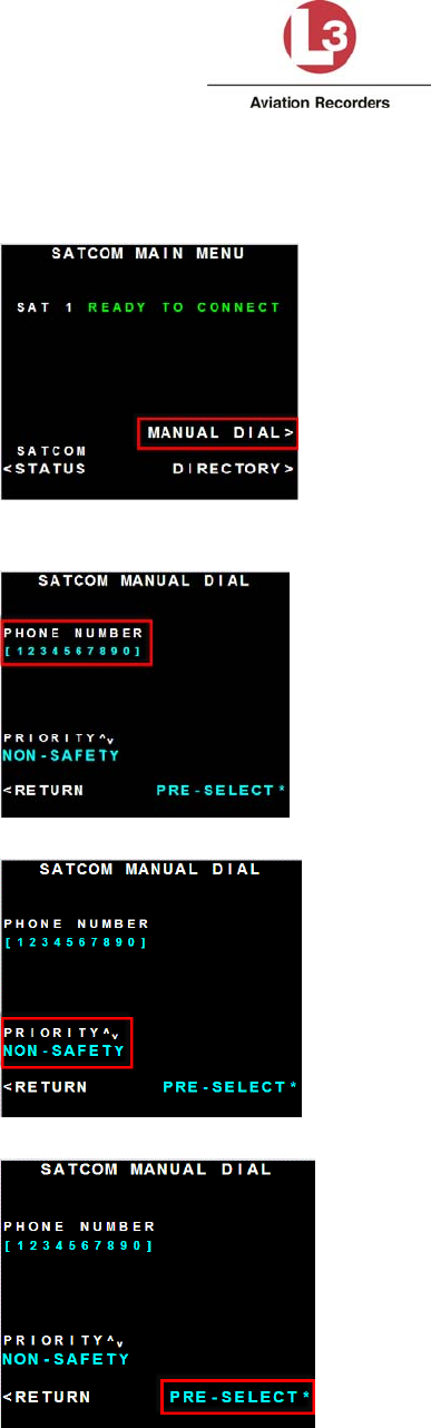
b. CallfromIridiumSATCOMPhonetoLandlinePhone(Manual)
1. SelectManualDialfromtheMCDUscreen.
2. Punchinthephonenumberandselectthebuttondirectlynexttotheopenfield
topopulatethefield.
3. ChooseaprioritybyusingthePageUpandPageDownbuttons.
4. ChoosePre‐Select.
AirbusIridiumSATCOMSystem
L‐3AviationRecordersProprietary
165E5733‐01Rev.02
7March2014Page16
5. Thesystemisreadytoconnectthecall.
6. Initiatethecall.
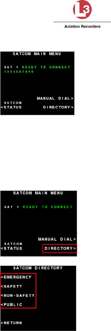
c. CallfromIridiumSATCOMPhonetoLandlinePhone
(Directory)
IMPORTANT:Ifmanualdialinghasbeendisabled,theabilitytousedual‐tonemulti‐
frequencysignaling(DTMF)willalsobedisabled.Thismeansthatyouwillnotbeableto
punchinanextensionnumberafterreachingaswitchboardviaDirectorydialing.
1. SelectDirectoryfromtheMCDUscreen.
2. Chooseadirectory.
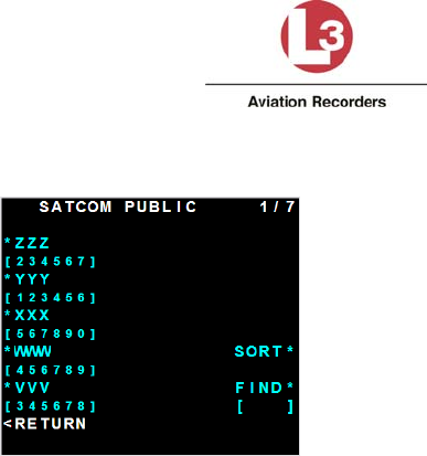
AirbusIridiumSATCOMSystem
L‐3AviationRecordersProprietary
165E5733‐01Rev.02
7March2014Page17
3. Locatethenumbertocall.
4. Initiatethecall.
2. SendDataMessagefromIridiumSATCOM
1. GototheMCDU.
2. ChooseafreetextandsendatestmessagetoDispatchorMaintenance.Thesystem
willautomaticallyqueueandsendthemessage.Optionally,youcanhavethe
messagereceiversendyouamessageback.
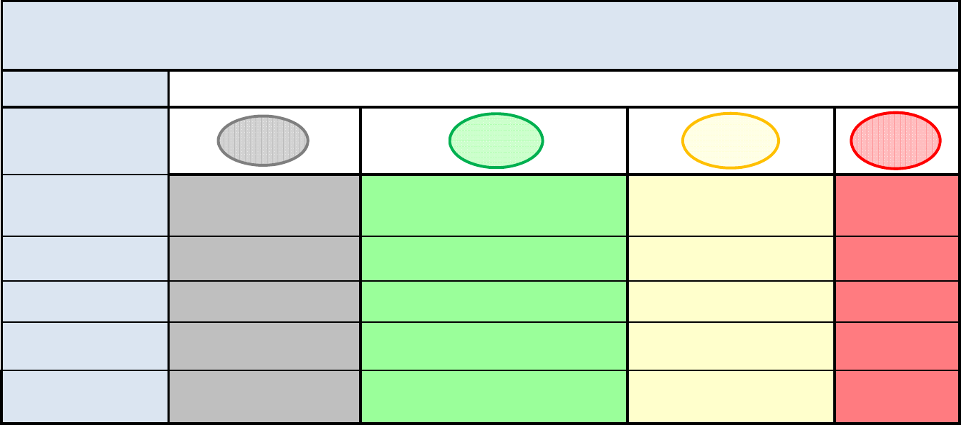
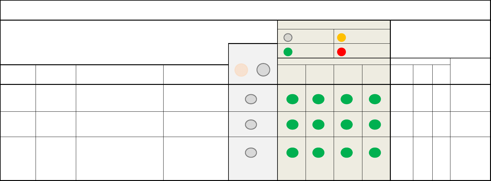
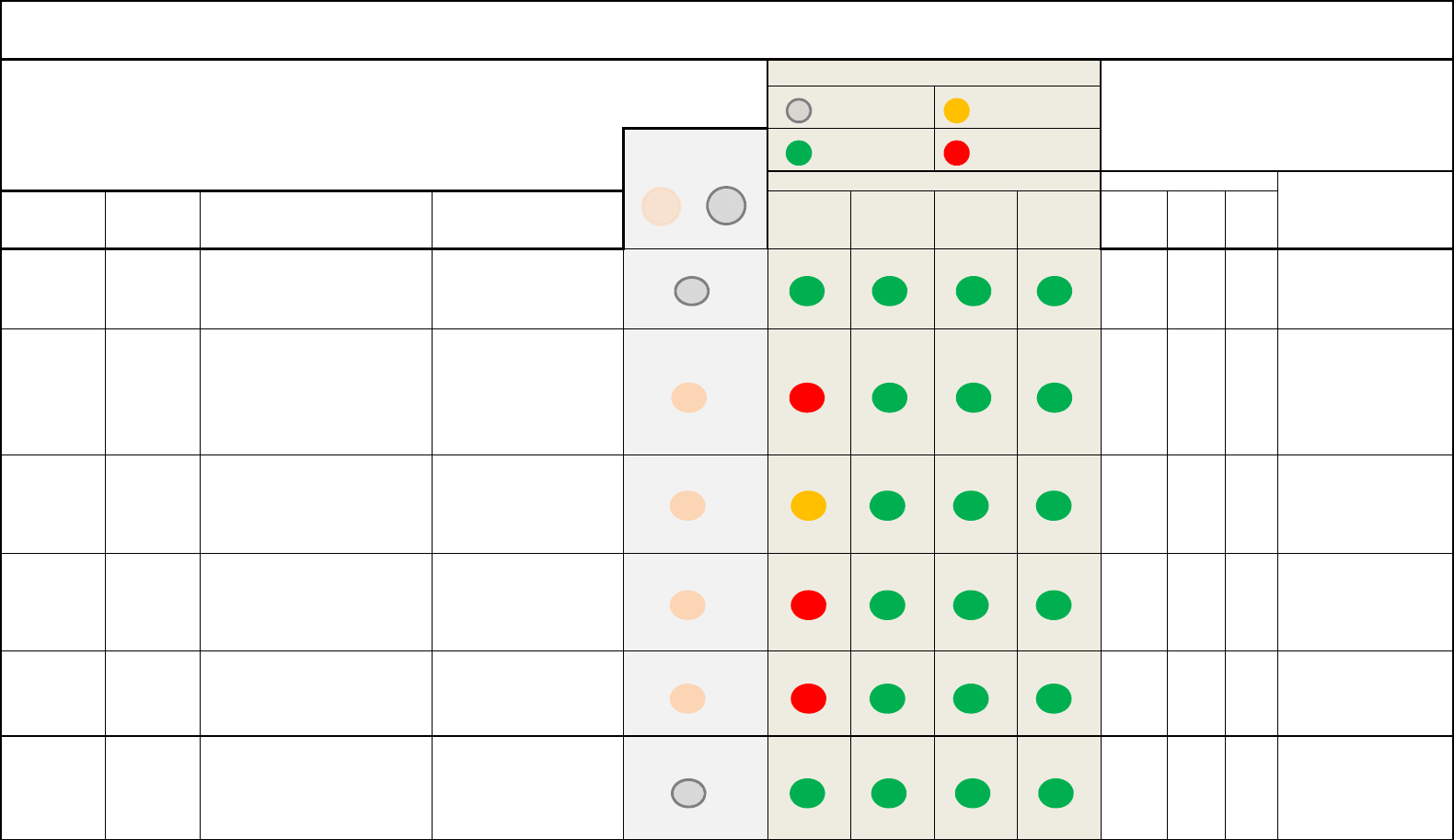
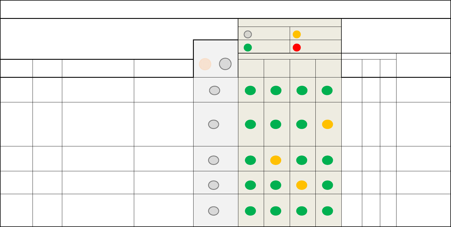
Status
Indicator Name
OFF GREEN YELLOW RED
System
Never Off Operational Mode
No Failure/Fault
Initialization Mode or
Maintenance Mode or
Fault/Event Critical Failure
ISVM Link
Never Off Operational Mode
No Failure/Fault Fault/Event Never Red
ISDM Link
Never Off Operational Mode
No Failure/Fault Fault/Event Never Red
GPS Link
Internal GPS Active
Parameter Set to Inactive Operational Mode
No Failure/Fault Fault/Event Never Red
Ethernet Link
(for each port)
Not Used or Fault Steady = Link OK
Flashing = Data Being Transmitted
Never Yellow Never Red
IridiumStatusIndicatorSummary
Note:LEDindicatorsrequirepowertotheIridiumSATCOMsystem.Everyindicatorwillbeoffifnopowerisapplied.
Indicator Color
(f
or eac
h
por
t)
Flashing
=
Data
Being
Transmitted
L‐3AviationRecordersProprietary
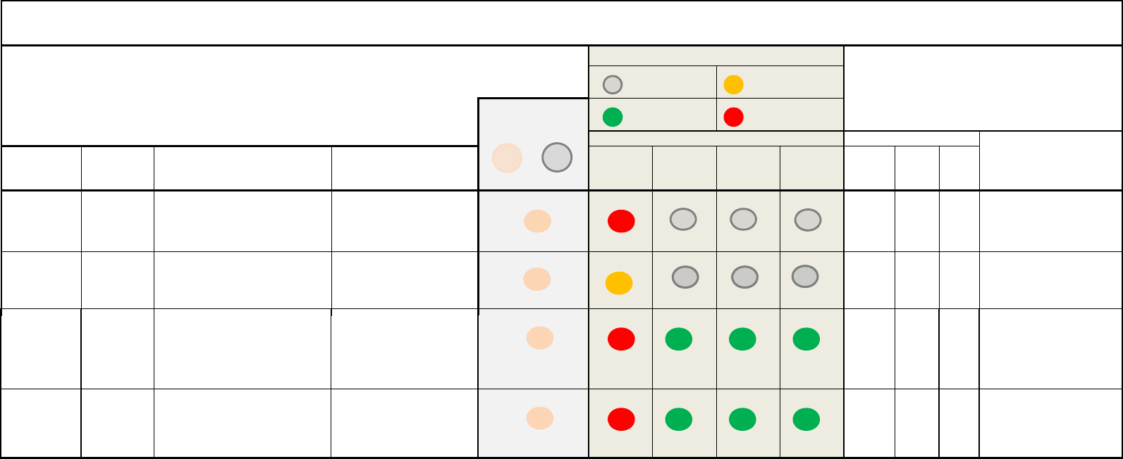
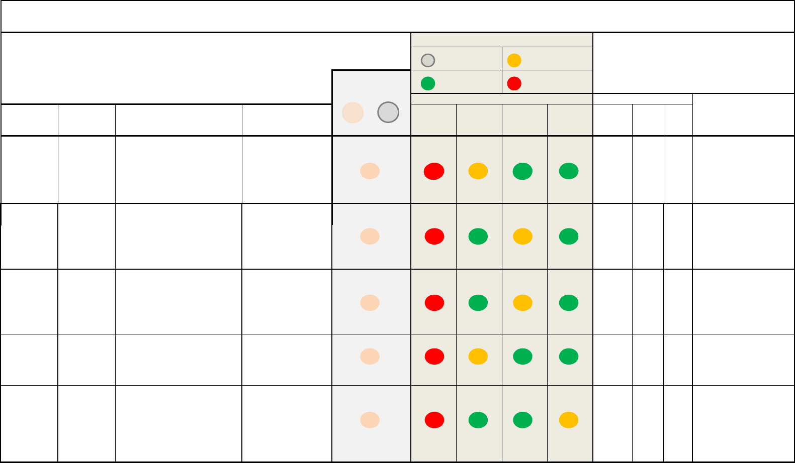
Fault Name BIT Check Raise Fault/Failure Condition Clear Fault/Failure
Condition System ISVM ISDM GPS Operable SDU SCM
CONFIG FAIL Configuration
Table Failure
The “Configuration Table Failure”
will be raised if the system is
unable to read or write the
Configuration Data stored in the
memory
The “Configuration Table
Failure” cannot be cleared
once raised.
No N/A N/A
Critical Error. Verify ICT and
ORT files in MUI. If files are
valid for A/C, replace SDU.
CONFIG
FAULT
SCM
Compatibility
Fault
The “SCM Compatibility Fault” will
be raised if the SDU software load
is not compatible with the valid
Configuration Data stored in the
SC
The “SCM Compatibility
Fault” cannot be cleared
once raised.
No N/A N/A
Transition to Configuration
Invalid State. Verify
software load in MUI.
Fault Light
Discrete Output
ON OFF
L-3 Iridium SATCOM System - Built-in Test and Fault Indicators
DATA CHECKS
Front Panel LEDs MCDU Indicators
Indicator Description
LED Off
Operational,
No Failure/Fault Critical Failure
Fault/Event
Comment
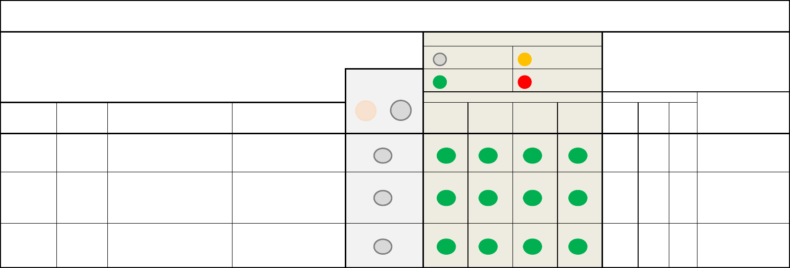
NVM FAIL NR-NVM
Failure
The “NR-NVM Failure” will be
raised if missing or not detected,
does not initialize or is judged to be
defective.
The “NR-NVM Failure”
cannot be cleared once
raised.
Yes FAIL OK Internal memory failure.
FLASH CARD
FAULT
Flash card
status
Flash card removed or can not be
read
Flash card inserted and can
be read. Yes FAIL OK
Verify flash card is inserted
and can be read.
L‐3AviationRecordersProprietary
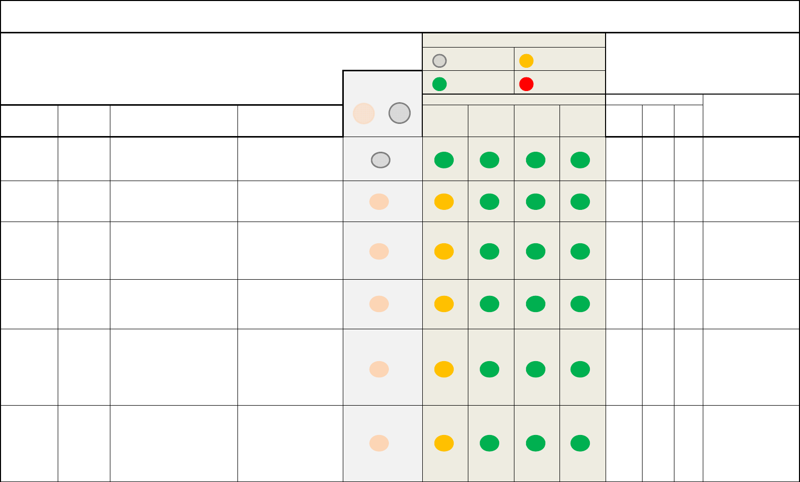
Fault Name BIT Check Raise Fault/Failure Condition Clear Fault/Failure Condition System ISVM ISDM GPS Operable SDU SCM
LOW VOLTS Low Voltage
Status
The “Low Voltage Status” will be
raised if the system enters the Low
Input Voltage state.
The “Low Voltage Status” will be
cleared if the system exits the
Low Input Voltage state.
Yes OK OK
Check input voltage if
persistent.
ALTERNATE
POWER
Alternate
Power Status
The “Alternate Power Status” will
be raised if the voltage at the
Alternate Input is below 18.0 V or
above 32.2 V.
The “Alternate Power Status”
will be cleared if the voltage at
the Alternate Input is within an
inclusive range of 18.0 V to 32.2
V.
Yes OK OK Check input voltage.
Comment
L-3 Iridium SATCOM System - Built-in Test and Fault Indicators
POWER CHECKS
Indicator Description
LED Off Fault/Event
Fault Light
Discrete Output
ON OFF
Operational,
No Failure/Fault Critical Failure
Front Panel LEDs MCDU Indicators
POWER LOSS Power Loss
Check
The “Power Loss Status” will be
raised if the system enters the
Power Failure state.
The “Power Loss Status” will be
cleared if the system exits the
Power Failure state.
No FAIL No Check input voltage.
L‐3AviationRecordersProprietary
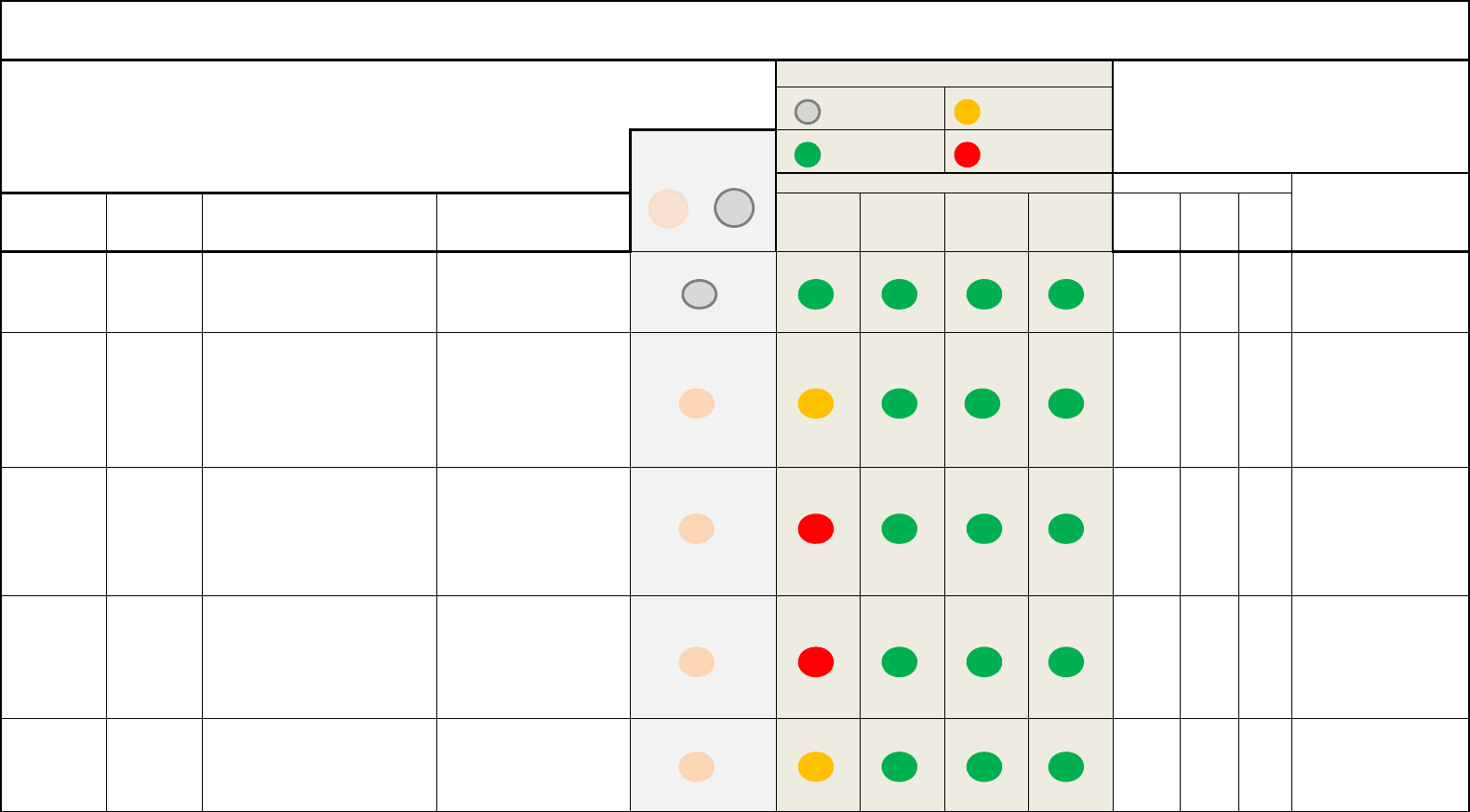
Fault Name BIT Check Raise Fault/Failure Condition Clear Fault/Failure
Condition System ISVM ISDM GPS Operable SDU SCM
CONFIG FAIL Temperature
Sensor Fault
A “Temperature Sensor Fault” will be
raised if one or more of the temperature
sensors are considered unreasonable.
The “Temperature Sensor
Fault” will be cleared if all of
the temperature sensors
report a reasonable
temperature
Yes OK OK
CONFIG
FAULT
System Low
Temperature
Status
The “System Low Temperature Status”
will be raised if the system enters the
System Low Temperature state.
The “System Low
Temperature Status” will be
cleared if the system exits
the System Low
Yes OK OK Temperature is
below -15 C.
NVM FAIL
ISVM Elevated
The
“
System High Temperature Status
”
The
“
System High
Yes
OK
OK
Temperature is
Comment
L-3 Iridium SATCOM System - Built-in Test and Fault Indicators
TEMPERATURE CHECKS
Indicator Description
LED Off Fault/Event
Fault Light
Discrete Output
ON OFF
Operational,
No Failure/Fault Critical Failure
Front Panel LEDs MCDU Indicators
NVM
FAIL
ISVM
Elevated
Temperature
Status, or ISVM
High
Temperature
Status, or System
High
Tt
The
System
High
Temperature
Status
will be raised if the system enters the
System High Temperature state.
The
System
High
Temperature Status” will be
cleared if the system exits
the System High
Temperature state.
Yes
OK
OK
Temperature
is
above 70 C.
L‐3AviationRecordersProprietary
Fault Name BIT Check Raise Fault/Failure Condition Clear Fault/Failure
Condition System ISVM ISDM GPS Operable SDU SCM
ISVM DPL
FAIL
ISVM Voice
Communication
Failure
The Iridium Satellite Voice Modem
(ISVM) failure will be raised if the
ISVM driver reports no communication
with the ISVM DPL port after three
retry attempts.
The “ISVM Voice
Communication Failure”
will be cleared if the ISVM
driver reports
communication with the
ISVM.
Yes FAIL OK
Voice communications not
available. Link should
reestablish within a few
minutes. If link does not
reestablish within 20 minute
period, replace SDU.
ISVM AT FAIL ISVM Data
Communication
Fil
The “ISVM Data Communication
Failure” will be raised if the Iridium All
Off M d i A i d h ISVM
The “ISVM Data
Communication Failure”
ill b l d if h ISVM
Non-Safety Services Data
Communications inoperable.
Li k h ld t bli h
Comment
L-3 Iridium SATCOM System - Built-in Test and Fault Indicators
INTERNAL CHECKS
Indicator Description
LED Off Fault/Event
Fault Light
Discrete Output
ON OFF
Operational,
No Failure/Fault Critical Failure
Front Panel LEDs MCDU Indicators
Failure Off Mode is not Active and the ISVM
driver reports no communication with
the ISVM AT port after three retry
attempts.
will be cleared if the ISVM
driver reports
communication with the
ISVM AT port.
Yes FAIL OK
Li
n
k
s
h
ou
ld
rees
t
a
bli
s
h
within a few minutes. If link
does not reestablish within
20 minute period, replace
SDU.
ISDM FAIL ISDM
Communication
Failure
The Iridium Satellite Data Modem
(ISDM) failure will be raised if the
ISDM driver reports no communication
with the ISDM DPL port after three
retry attempts.
The “ISDM Voice
Communication Failure”
will be cleared if the ISDM
driver reports
communication with the
ISDM.
Yes FAIL OK
Safety Services Data
Communications inoperable.
Link should reestablish
within a few minutes. If link
does not reestablish within
20 minute period, replace
S
D
U
.
SIM CARD
FAIL SIM
Communication
Failure
The “SIM Communication Failure” will
be raised if the system fails to read or
write to the SIM card.
The “SIM Communication
Failure” will be cleared if
the system successfully
reads and writes to the SIM
card.
Yes OK FAIL
Voice Communications not
available. Verify SIM card is
installed and SCM is
operational.
GPS FAIL GPS
Communication
Fail
The “GPS Communication Failure” will
b
e raised if the GPS Receiver reports no
communication with the GPS after three
retry attempts.
The “GPS Communication
Failure” will be cleared if
the GPS Receiver reports
communication with the
GPS. Yes FAIL OK
GPS not available, Link
should reestablish within a
few minutes. If link does not
reestablish within 20 minute
period, replace SDU. If still
present verify Iridium/GPS
antenna and cable
an
t
enna an
d
ca
bl
e.
L‐3AviationRecordersProprietary
Fault Name BIT Check Raise Fault/Failure Condition Clear Fault/Failure
Condition System ISVM ISDM GPS Operable SDU SCM
A717
INACTIVE
ARINC
573/717
Receiver
Inactive Fault
The “ARINC 573/717 Receiver fault
will be raised if the ARINC 573/717
is configured Active data and the
data is not present.
The ARINC 573/717
Receiver Fault will be cleared
if ARINC 573/717 data
resumes.
Yes OK OK
Verify ARINC 573/717
data.
A429 RXnn
INACT (nn =
Port Number)
ARINC 429
Receiver Port
Inactive Fault
An “ARINC 429 Receiver Port
Inactive Fault” will be raised if an
ARINC 429 Receiver Port that is
configured as Generic 429 has not
A raised “ARINC 429
Receiver Port Inactive Fault”
will be cleared if a recognized
label with correct parity is
f
Yes OK OK
Verify ARINC 429 data on
indicated receiver port.
The
“
ACARS 1 Receiver Port
Araised
“
ACARS 1 Receiver
Comment
L-3 Iridium SATCOM System - Built-in Test and Fault Indicators
EXTERNAL CHECKS
Indicator Description
LED Off Fault/Event
Fault Light
Discrete Output
ON OFF
Operational,
No Failure/Fault Critical Failure
Front Panel LEDs MCDU Indicators
ACARS1 RX
INACT
ACARS 1
Receiver Port
Inactive Fault
The
ACARS
1
Receiver
Port
Inactive Fault” will be raised if an
ARINC 429 Receiver Port
configured as ACARS 1 has not
received a recognized label with
correct parity for 4 seconds in a
A
raised
ACARS
1
Receiver
Port Inactive Fault” will be
cleared if a recognized label
with correct parity is received
for 4 seconds in a row over
the port for which the
Yes OK OK
Verify ACARS 1 receiver
data.
ACARS2 RX
INACT
ACARS 2
Receiver Port
Inactive Fault
The “ACARS 2 Receiver Port
Inactive Fault” will be raised if an
ARINC 429 Receiver Port
configured as ACARS 2 has not
received a recognized label with
A raised “ACARS 2 Receiver
Port Inactive Fault” will be
cleared if a recognized label
with correct parity is received
for 4 seconds in a row over
Yes OK OK
Verify ACARS 2 receiver
data.
MCDU1 RX
INACT
MCDU 1
Receiver Port
Inactive Fault
The “MCDU 1 Receiver Port
Inactive Fault” will be raised if an
ARINC 429 Receiver Port
configured as ARINC 739 MCDU 1
has not received a recognized label
with correct parity for 4 seconds in
a row.
A raised “MCDU 1 Receiver
Port Inactive Fault” will be
cleared if a recognized label
with correct parity is received
for 4 seconds in a row over
the port for which the “MCDU
1 Receiver Port Inactive
Fault” was raised.
No
(MCDU
1)
OK OK
Display on MCDU 1
inoperable. Check MCDU
1.
MCDU2 RX
INACT
MCDU 2
Receiver Port
Inactive Fault
The “MCDU 2 Receiver Port
Inactive Fault” will be raised if an
ARINC 429 Receiver Port
configured as ARINC 739 MCDU 1
has not received a recognized label
A raised “MCDU 2 Receiver
Port Inactive Fault” will be
cleared if a recognized label
with correct parity is received
for 4 seconds in a row over
No
(MCDU
2)
OK OK
Display on MCDU 2
inoperable. Check MCDU
2
Inactive
Fault
has
not
received
a
recognized
label
with correct parity for 4 seconds in
a row.
the port for which the “MCDU
1 Receiver Port Inactive
Fault” was raised.
2)
2
.
L‐3AviationRecordersProprietary
Fault Name BIT Check Raise Fault/Failure Condition Clear Fault/Failure
Condition System ISVM ISDM GPS Operable SDU SCM
A717
INACTIVE
ARINC
573/717
Receiver
Inactive Fault
The “ARINC 573/717 Receiver fault
will be raised if the ARINC 573/717
is configured Active data and the
data is not present.
The ARINC 573/717
Receiver Fault will be cleared
if ARINC 573/717 data
resumes.
Yes OK OK
Verify ARINC 573/717
data.
Comment
L-3 Iridium SATCOM System - Built-in Test and Fault Indicators
EXTERNAL CHECKS
Indicator Description
LED Off Fault/Event
Fault Light
Discrete Output
ON OFF
Operational,
No Failure/Fault Critical Failure
Front Panel LEDs MCDU Indicators
MCDU3 RX
INACT
MCDU 3
Receiver Port
Inactive Fault
The “MCDU 3 Receiver Port
Inactive Fault” will be raised if an
ARINC 429 Receiver Port
configured as ARINC 739 MCDU 1
has not received a recognized label
A raised “MCDU 3 Receiver
Port Inactive Fault” will be
cleared if a recognized label
with correct parity is received
for 4 seconds in a row over
No
(MCDU
3)
OK OK Display on MCDU 3
inoperable.
Inactive
Fault
has
not
received
a
recognized
label
with correct parity for 4 seconds in
a row.
the port for which the “MCDU
1 Receiver Port Inactive
Fault
”
was raised
3)
A
429 TXn FAIL
(n = Port
Number)
ARINC 429
Transmitter
Port
Loopback
Failure
An “ARINC 429 Transmitter Port
Loopback Failure” will be raised if
an active ARINC 429 Transmitter
Port is configured as a GP Bus or
CFDS and the loopback from the
port is not detected.
A raised “ARINC 429
Transmitter Port Loopback
Failure” will be cleared if the
loopback is detected from the
port for which the “ARINC
429 Transmitter Port
Loopback Fault” was raised.
Yes FAIL OK
Verify ARINC 429 data on
indicated transmitter port.
ACARS TX
FAIL
ACARS
Transmitter
Port
Loopback
Failure
The “ACARS Transmitter Port
Loopback Failure” will be raised if
an ARINC 429 Transmitter Port is
configured as ACARS and the
loopback from the port is not
detected.
A
raised “ACARS Transmitter
Port Loopback Failure” will
be cleared if the loopback is
detected from the port for
which the “ACARS
Transmitter Port Loopback
Failure” was raised.
Yes FAIL OK
Verify ACARS transmitter
port.
A
CARS FAULT ACARS Loop
Test Fault
The “ACARS Loop Test Fault” will
be raised if an ACARS Loop Test
does not pass on at least one
ACARS system.
Yes OK OK Verify ACARS system.
L‐3AviationRecordersProprietary
Fault Name BIT Check Raise Fault/Failure Condition Clear Fault/Failure
Condition System ISVM ISDM GPS Operable SDU SCM
A717
INACTIVE
ARINC
573/717
Receiver
Inactive Fault
The “ARINC 573/717 Receiver fault
will be raised if the ARINC 573/717
is configured Active data and the
data is not present.
The ARINC 573/717
Receiver Fault will be cleared
if ARINC 573/717 data
resumes.
Yes OK OK
Verify ARINC 573/717
data.
Comment
L-3 Iridium SATCOM System - Built-in Test and Fault Indicators
EXTERNAL CHECKS
Indicator Description
LED Off Fault/Event
Fault Light
Discrete Output
ON OFF
Operational,
No Failure/Fault Critical Failure
Front Panel LEDs MCDU Indicators
MCDU TX FAIL
MCDU
Transmitter
Port
Loopback
The “MCDU Transmitter Port
Loopback Failure” will be raised if
an ARINC 429 Transmitter Port is
configured as ARINC 739 MCDU
dh l b kf h i
A raised “MCDU Transmitter
Port Loopback Failure” will
be cleared if the loopback is
detected from the port for
which the
“
MCDU
No FAIL OK Verify MCDU system.
Loopback
Failure and the loopback
f
rom the port is
not detected.
which
the
MCDU
Transmitter Port Loopback
Failure” was raised.
SERIALn
FAULT (n =
Port Number)
RS-232/422
Receive Fault
A “RS-232/422 Receive Fault” will
be raised for any active RS-
232/422 Serial Port for which a
received data error is reported.
A raised “RS-232/422
Receiver Fault” will be
cleared if the data is received
without error over the port for
which the fault was raised.
Yes OK OK
Verify received serial data
on indicated port.
SERIALn FAIL
(n = Port
Number)
RS-232/422
Transmission
Loopback
Failure
The “RS-232/422 Transmission
Loopback Failure” will be raised for
any Active RS-232 Serial Port
whose loopback is not detected
after three loopback attempts.
The “RS-232/422
Transmission Loopback
Failure” cannot be cleared
once raised.
Yes FAIL OK Verify serial data on
indicated port.
DOUTn FAIL (n
= Port Number)
Discrete
Output Failure
A “Discrete Output Failure” will be
raised for any Discrete Output Port
that is Active and does not output
the expected voltage.
The “Discrete Output Failure”
will be cleared if the expected
voltage is output from the
port for which the fault was
raised.
Yes FAIL OK
Verify discrete output on
indicated port.
ETHERNETn
FAULT (n =
Port Number)
Ethernet Link
Fault
The “Ethernet Link Fault” will be
raised if Ethernet is Monitored and
there is no link.
The “Ethernet Link Fault” will
be cleared if Ethernet is
Monitored and there is a link.
Yes OK OK
Verify indicated Ethernet
port. Access to MUI may
be impacted, may need to
access MUI through
another Ethernet port.
another
Ethernet
port.
L‐3AviationRecordersProprietary
Fault Name BIT Check Raise Fault/Failure Condition Clear Fault/Failure
Condition System ISVM ISDM GPS Operable SDU SCM
A717
INACTIVE
ARINC
573/717
Receiver
Inactive Fault
The “ARINC 573/717 Receiver fault
will be raised if the ARINC 573/717
is configured Active data and the
data is not present.
The ARINC 573/717
Receiver Fault will be cleared
if ARINC 573/717 data
resumes.
Yes OK OK
Verify ARINC 573/717
data.
Comment
L-3 Iridium SATCOM System - Built-in Test and Fault Indicators
EXTERNAL CHECKS
Indicator Description
LED Off Fault/Event
Fault Light
Discrete Output
ON OFF
Operational,
No Failure/Fault Critical Failure
Front Panel LEDs MCDU Indicators
NO GPS LINK GPS Link
Status
The “GPS Link Status” will be
raised if the internal GPS is
configured as Active and the GPS
Ri t iti
The “GPS Link Status” will be
cleared if the GPS Receiver
r
epo
r
ts
a
n
a
vi
gat
i
o
n
so
l
ut
i
o
n Yes OK OK
GPS not available, Link
should reestablish within a
few minutes. If link does
not reestablish within 20
min
ute
pe
ri
od,
r
ep
l
ace
Status
R
ece
i
ver repor
t
s no nav
i
ga
ti
on
solution for 5 seconds in a row.
reports
a
navigation
solution
for 5 seconds in a row.
minute
period,
replace
SDU. If still present verify
Iridium/GPS antenna and
cable.
NO ISVM LINK ISVM Link
Status
The “ISVM Link Status” will be
raised if the ISVM driver reports no
link.
The “ISVM Link Status” will
be cleared if the ISVM driver
reports a link for 5 seconds in
a row.
Yes OK OK
Voice communications not
available. Link should
reestablish within a few
minutes.
NO ISDM LINK ISDM Link
Status
The “ISDM Link Status” will be
raised if the ISDM driver reports no
link.
The “ISDM Link Status” will
be cleared if the ISDM driver
reports a link for 5 seconds in
a row.
Yes OK OK
Data communications not
available. Link should
reestablish within a few
minutes.
NO DTP
SOURCE
Date, Time,
Position
Source Status
The “DTP Source Status” will be
raised if DTP 1 interface, DTP 2
interface, DTP 3 interface, and
internal GPS are all not providing
valid data.
The “DTP Source Status” will
be cleared if at least one of
DTP 1 interface, DTP 2
interface, DTP 3 interface, or
internal GPS is providing
valid data.
Yes OK OK Verify DTP source.
L‐3AviationRecordersProprietary

Iridium SIM Card Registration
The Iridium network is based on the international Global System for Mobile
communications (GSM) standard and architecture. With any GSM cellular device, all Iridium
transceivers capable of voice require a Subscriber Identity Module (SIM) associated with the
mobile device. Though the SIM can be used for many functions, such as restricting call access or
to store information, its primary function is to assign the telephone number to the L-3 Satellite
Data Unit (SDU) transceiver. An exception is the Iridium Short Burst Data (SBD) modem, which
operates solely from an IMEI number assigned to each modem.
Often customers or installers are not familiar with the need to activate the SIM and IMEI
for service over the Iridium network prior to testing or use of the system. You may select any
valid Iridium Service provider. Our recommendation is to contact our partner, FLYHT Aerospace
Solutions Ltd., complete the following activation form, and send to FLYHT for processing.
There are two types of voice service plans to choose from:
• Air Traffic Service (ATS)
The operator will be able to prioritize calls to and from the cockpit and pre-empt
a lower priority call with a higher priority incoming call. The calls from ground-to-
air have additional security procedures; the user will be required to have a User
ID, PIN, plane ID, and set the call priority.
• Non-ATS
This service does not have call prioritization and the ground-to-air calls only
require the phone number of the SIM card to place a call.
You may need the following information when activating a SIM card:
• Tail Number
• IMEI Voice Modem Number
• Avionics MFR – L-3/FLYHT
• IMEI Data Modem Number
• Avionics Model - AFIRS 228S Satellite Data Unit
• Voice Modem Model 9523
• Data Modem Model 9602

CongratulationsonpurchasingtheFLYHTAFIRSTM228Ssystem.
Inordertocompletetheactivationofthevoiceanddataserviceswerequiresomeadditional
information.
Pleasereviewthefollowingvoiceanddataserviceoptionsandemailthecompletedformtous
at228SVoice/DataServices@FLYHT.com.AFLYHTServiceandSupportManagerwillcontact
youtocompletetheactivationprocessandtoprovideyouwiththeassignedsatcomphone
number.
1. AircraftInformation:
Model:
SerialNumber:
Registration:
2. AFIRS228Information:
SDUSerial
Number:
SCMSerial
Number
3. Pleaseselectoneofthefollowingsatcomvoiceserviceplanoptions:
AFIRSGlobalVoice/DataPlan–NONATS Rate BillingIntervals
AirtoGround$1.45/minUSD20seconds
GroundtoAir$1.45/minUSD20seconds
CircuitSwitchDataforEFB$1.45/minUSD20seconds
Note1:CallstootherSATCOMserviceproviderswillbechargedatarateof$8.50/min
Note2:Minimummonthlyfeeof$50willapplytoallaccounts
AFIRSGlobalVoice/DataPlan–ATS Rate BillingIntervals
AirtoGround$1.45/minUSD20seconds
GroundtoAir$1.75/minUSD20seconds
CircuitSwitchDataforEFB$1.45/minUSD20seconds
Note:CallstootherSATCOMserviceproviderswillbechargedatarateof$8.50/min
Note2:Minimummonthlyfeeof$50willapplytoallaccounts

4. PleaseindicateyourACARSsatcomdataserviceprovider:
ARINC
SITA
PleasenoteyouwillrequireaseparateagreementwithyourselectedACARSsatcomdata
serviceprovider.
5. Contactinformation:
Primarycontact*BillingContact(ifdifferent)
Company
Name
Address:
email:
Phone:
*Thesatcomvoicephonenumberwillbeprovidedtothiscontactuponactivation.

TermsandConditions
TERMSOFPAYMENT
Paymentnetthirty(30)daysfromdateofinvoiceorasotherwisespecifiedbySeller.Buyer
agreestopaytheentirenetamountofeachinvoicefromSellerpursuanttothetermsofeach
suchinvoicewithoutoffsetordeduction.OrdersaresubjecttocreditapprovalbySeller,which
mayinitssolediscretionatanytimechangethetermsofbuyer’scredit,requirepaymentin
cash,bankwiretransferorbyofficialcheckand/orrequirepaymentofanyorallamountsdue
ortobecomedueforBuyer’sorderbeforeshipmentofanyoralloftheproducts.Ifseller
believesingoodfaiththatBuyer’sabilitytomakepaymentsmaybeimpairedorifBuyershall
failtopayanyinvoicewhendue,Sellermaysuspendthedeliveryofanyorderoranyremaining
balancethereofuntilsuchpaymentismadeorcancelanyorderoranyremainingbalance,
thereof,andbuyershallremainliabletopayforanyproductsalreadyshippedandallNon‐
StandardProductsorderedbyBuyer.Buyeragreestosubmitsuchfinancialinformationfrom
timetotimeasmaybereasonablyrequestedbySellerfortheestablishmentand/or
continuationofcreditterms.Checksareacceptedsubjecttocollectionandthedateofthe
collectionshallbedeemedthedateofpayment.AnycheckreceivedfromBuyermaybeapplied
bySelleragainstanyobligationowingfromBuyertoSeller,regardlessofanystatement
appearinginorreferringtoBuyershallpayinterestonanyinvoicenotpaidwhenduefromthe
duedatetothedateofpaymentattherateofoneandone‐half(1‐1/2%)percentpermonthor
suchlowerrateasmaybemaximumallowablebylaw.IfBuyerfailstomakepaymentwhendue
Sellermaypursueanylegalorequitableremedies,inwhicheventSellershallbeentitledto
reimbursementforcostsofcollectionandreasonableattorneysfees.
PRIVACYPOLICY
FLYHTAerospaceSolutionsLtd.(FLYHT)usestheinformationcollectedtofulfillyourrequestsfor
servicesandtofacilitatebilling.FLYHTwillsendpersonallyidentifiableinformationaboutyou
and/oryourcompanytoothercompaniesorpeoplewhen:weneedtoshareyourinformation
toprovidetheserviceyouhaverequested,weneedtosendtheinformationtocompanieswho
workonbehalfofFLYHTtoprovideservicetoyou(unlesswetellyoudifferentlythese
companiesdonothaveanyrighttousethepersonallyidentifiableinformationweprovidethem
beyondwhatisnecessarytoassistus).Personallyidentifiableconsumerinformationisshared
withthirdparties(suchasbanksandcreditcardprocessors)totheextentnecessaryforFLYHT
tocollectpaymentfortheservicesprovided.

CUSTOMERAGREEMENT
Asanindividualorauthorizedrepresentativeofthecompany,Iherebycertifythatthe
informationprovidedonthisformistrueandcorrect.IauthorizeFLYHTAerospaceSolutions
Ltd.(FLYHT)toinvestigatefinancialreferencesandallotherrelevantmaterial.FLYHThasthe
righttodenyservicetoanyaccountthatispastdueandalsoreservestherighttodenyservice
baseduponinformationsupplied.Iunderstandthatourcompanyisresponsibleforallcharges
andservicesuptillthedateouraccountisproperlycancelledthroughFLYHTandtheIridium
network.IagreethatFLYHTcannotbeheldliableforanyclaimsduetounavailability,delay,or
interruptioninsatelliteservices.Suchclaimsshallalsoextendtodamage,expense,andlossof
life.IagreetotheTermsofPaymentandthePrivacyPolicy.
Ihavereadandagreetothestandardtermsandconditionsabove.Signedthis dayof ,20:
Signature:
PrintName
Title
Company
Address:
email:
Phone:

L-3 Aviation Recorders Proprietary
100 Cattlemen Road
Sarasota, FL 34232
Installation Manual
Airbus Iridium SATCOM System
SDU L-3 part number 228E5733-00
SCM L-3 part number 418E5733-00
Publication Number: 165E5733-00
Issue: Rev. 02
21 January 2014

L-3 Aviation Recorders Proprietary
100 Cattlemen Road
Sarasota, FL 34232
EXPORT CONTROL STATEMENT IRIDIUM SATCOM
TECHNOLOGY / DATA:
“This Iridium SATCOM System Technical Data is being exported from
the United States in accordance with the Export Administration
Regulations (ECCN #7A994), No License Required (NLR). Diversion
contrary to U.S. law is prohibited. In accordance with U.S. Law (Title
15CFR Part 746 and Supplement No. 1 to Part 774; and Title 31CFR)
resale/re-export or transfer to certain designated countries is
prohibited without the prior written consent of the U.S. Department of
Commerce.”
HTSUS/Schedule B: 85439.09.000
This manual contains date sensitive information. To verify the latest
revision level of this manual, visit our document down-load site at
http://www.L3ar.net.
©Copyright 2013 by L-3 Communications.
All rights reserved. No part of this manual may be reproduced or
utilized in any form or by any means, electronic or mechanical,
including photocopying, recording, or by information storage and
retrieval system, without permission in writing.
Inquiries should be addressed to:
L-3 Communications,
Aviation Recorders Publications
Vendor Code: 06141 P. O. Box 3041
Sarasota, Florida 34230
Phone: (941) 371–0811;
FAX: (941) 377–5591

L-3 Aviation Recorders Proprietary
100 Cattlemen Road
Sarasota, FL 34232
Record of Revisions
Rev. Issue Date Description Pages By
00 01 November 2013 Initial issue. All CM
01 15 December 2013 Corrected SDU & SCM Top-
Level Part Numbers.
All CM/SC
02 21 January 2014 Corrected SDU & SCM Top-
Level Part Numbers.
All CP

Airbus Iridium SATCOM System
165E5733-00 L-3 Aviation Recorders Proprietary
Issue, Rev. 02
21 January 2014
Page 4
Table of Contents
1.Introduction ............................................................................................................................. 9
1.1Applicability ..................................................................................................................... 9
1.2Model Designation .......................................................................................................... 9
1.2.1Airbus Iridium SATCOM System ....................................................................... 9
1.3Part Numbers ................................................................................................................. 9
1.4Reference Documents .................................................................................................... 9
1.5Definitions of Acronyms and Terms .............................................................................. 12
2.Description and Operation .................................................................................................... 16
2.1System Overview .......................................................................................................... 16
2.2System Architecture ..................................................................................................... 16
2.3External System Interfaces ........................................................................................... 17
3.Equipment Specifications ..................................................................................................... 20
3.1Satellite Data Unit (SDU) .............................................................................................. 20
3.1.1General ............................................................................................................ 21
3.1.2Mechanical Specifications ............................................................................... 21
3.1.3Environmental Specifications – Airbus Iridium SATCOM System ................... 22
3.2SDU Configuration Module (SCM) ............................................................................... 22
3.2.1General ............................................................................................................ 22
3.2.2Mechanical Specifications ............................................................................... 23
3.2.3Environmental Specifications ........................................................................... 25
3.3Airbus Iridium SATCOM System Satellite Antenna ...................................................... 25
3.4Antenna Coaxial Cable ................................................................................................. 26
3.5Interface Specifications ................................................................................................ 26
SDU Rear Connector (J1) ............................................................................................ 27
3.5.1Power Input ...................................................................................................... 29
3.5.2Chassis Ground ............................................................................................... 29
3.5.3ARINC 429 Digital Serial Bus Input ................................................................. 30
3.5.4ARINC 429 Digital Serial Bus Output .............................................................. 30
3.5.5Ethernet ........................................................................................................... 30
3.5.6Discrete Inputs ................................................................................................. 30
3.5.6.1Configurable Inputs .......................................................................................... 30
3.5.7Discrete Outputs .............................................................................................. 31

Airbus Iridium SATCOM System
165E5733-00 L-3 Aviation Recorders Proprietary
Issue, Rev. 02
21 January 2014
Page 5
3.5.7.1Configurable Outputs ....................................................................................... 31
3.5.8Two-Wire Phone .............................................................................................. 31
3.5.9Microphone Input ............................................................................................. 31
3.5.10Iridium / GPS Antenna ..................................................................................... 32
3.6SDU Maintenance Connector (J2) ................................................................................ 32
3.7SDU Configuration Module (SCM) ............................................................................... 32
3.8ARINC 429 Receiver Protocols .................................................................................... 32
3.9ARINC 429 Receiver Activity Status ............................................................................. 34
3.10ARINC 429 Transmitter Protocols ................................................................................ 34
3.10.1From SDU to ATSU / FWC .............................................................................. 34
3.10.2From SDU to MCDU ........................................................................................ 35
3.10.3From SDU to Airbus CFDS .............................................................................. 35
4.Installation Considerations .................................................................................................... 36
4.1Satellite Data Unit (SDU) .............................................................................................. 36
4.2SDU Configuration Module (SCM) ............................................................................... 37
4.3Iridium Antenna System ............................................................................................... 37
4.3.1Antenna ........................................................................................................... 37
4.3.2Antenna Mounting ............................................................................................ 39
4.3.3Coaxial Cable .................................................................................................. 39
5.SATCOM Installation Materials ............................................................................................. 41
5.1Required Materials ....................................................................................................... 41
6.System Interface Wiring ........................................................................................................ 42
6.1General ......................................................................................................................... 42
6.2Primary Power, Antenna, and SCM .............................................................................. 42
6.3ARINC 429 Interfaces ................................................................................................... 42
6.3.1Receiver Protocols ........................................................................................... 43
6.3.2Transmitter Protocols ....................................................................................... 43
6.4MCDU ........................................................................................................................... 44
6.5ACARS ATSU ............................................................................................................... 45
6.6CFDIU Interface ............................................................................................................ 46
6.7Date, Time and Position ............................................................................................... 46
6.8RS-232/422 Databus .................................................................................................... 46
6.9Ethernet ........................................................................................................................ 47
6.10Discrete Inputs .............................................................................................................. 48
6.10.1Landing Gear Control Interface Unit (LGCIU) Input ......................................... 48
6.10.2Function Assignment ....................................................................................... 49

Airbus Iridium SATCOM System
165E5733-00 L-3 Aviation Recorders Proprietary
Issue, Rev. 02
21 January 2014
Page 6
6.11Discrete Outputs ........................................................................................................... 50
6.12SATCOM ...................................................................................................................... 50
6.12.1Audio Integrating System ................................................................................. 50
7.SATCOM System Configuration ........................................................................................... 52
7.1Accessing the Maintenance User Interface (MUI) ........................................................ 53
7.1.1Home Page Tab Descriptions .......................................................................... 54
7.1.2Faults Page ...................................................................................................... 55
7.1.3Part Numbers Page ......................................................................................... 56
7.2Entering Maintenance Mode ......................................................................................... 57
7.2.1Maintenance Mode Menu Descriptions ........................................................... 60
7.3Configuring the Airbus Iridium SATCOM System ......................................................... 65
7.3.1Address Book .................................................................................................. 65
7.3.2Owner Requirements Table (ORT) Parameters .............................................. 66
7.3.3Installation Configuration Table (ICT) .............................................................. 68
7.3.4User Access Table (UAT) Parameters ............................................................ 68
7.4Upgrading Airubs Iridium SATCOM System Software.................................................. 70
7.4.1Upgrade Materials ........................................................................................... 70
7.4.2Upgrade Procedure ......................................................................................... 70
7.5Exiting Maintenance Mode ........................................................................................... 73
8.Maintenance and Checkout .................................................................................................. 75
8.1Post-Installation Checkout ............................................................................................ 75
8.1.1Before Power-On Tests ................................................................................... 75
8.1.2Aircraft Systems Interface Tests ...................................................................... 76
8.1.3Operational System Tests ............................................................................... 77
8.1.4EMI Tests ......................................................................................................... 78
8.2Instructions for Continued Airworthiness ...................................................................... 78
List of Figures
Figure 2-1 – Airbus Iridium SATCOM System Operational Concept .......................................... 16
Figure 2-2 – Airbus Iridium SATCOM System Block Diagram .................................................... 17
Figure 2-3 – Airbus Iridium SATCOM System External Interfaces ............................................. 18
Figure 3-1 – Airbus Iridium SATCOM System Satellite Data Unit (SDU) ................................... 20
Figure 3-2 – SDU Outline Drawing ............................................................................................. 21
Figure 3-3 – Airbus Iridium SATCOM System SDU Configuration Module (SCM) ..................... 22

Airbus Iridium SATCOM System
165E5733-00 L-3 Aviation Recorders Proprietary
Issue, Rev. 02
21 January 2014
Page 7
Figure 3-4 – SCM Outline Drawing ............................................................................................. 23
Figure 3-5 – SCM Oblique View ................................................................................................. 24
Figure 3-6 – SCM Connector View Showing Location of Pin 1 .................................................. 25
Figure 3-7 – Airbus Iridium SATCOM System Antenna .............................................................. 25
Figure 3-8 – Iridium Antenna Coaxial Cable and Connectors .................................................... 26
Figure 3-9 – SDU Connector Map .............................................................................................. 29
Figure 4-1 – 2MCU Mounting Tray ............................................................................................. 36
Figure 4-2 – Iridium Antenna, Outline and Dimensions .............................................................. 38
Figure 4-3 – Iridium Antenna, Gasket ......................................................................................... 39
Figure 4-4 – Iridium Antenna, Coaxial Cable .............................................................................. 40
Figure 6-1 – Primary Power, Antenna, and SCM Interface ........................................................ 42
Figure 6-2 – MCDU Interface ...................................................................................................... 44
Figure 6-3 – ACARS ATSU Interface ......................................................................................... 45
Figure 6-4 – CFDIU Interface ..................................................................................................... 46
Figure 6-5 – Serial Port Interface ................................................................................................ 47
Figure 6-6 – Ethernet Interface ................................................................................................... 48
Figure 6-7 – Discrete Input Interfaces ........................................................................................ 50
Figure 6-8 – Latched ACP Audio Interface ................................................................................. 51
Figure 7-1 – Maintenance Port Location ..................................................................................... 52
Figure 7-2 – Home Page – General Tab .................................................................................... 54
Figure 7-3 – Faults Page (Fault Log Tab) ................................................................................... 55
Figure 7-4 – Faults Page (Fault History Tab) ............................................................................. 55
Figure 7-5 – Part Numbers Page (Software Tab) ....................................................................... 56
Figure 7-6 – Part Numbers Page (Hardware Tab) ...................................................................... 56
Figure 7-7 – Entering Maintenance Mode Message ................................................................... 57
Figure 7-8 – Maintenance Mode Initial Display Screen .............................................................. 58
Figure 7-9 – Maintenance Mode Exit Screen ............................................................................. 59
Figure 7-10 – System Restart Screen ........................................................................................ 59
Figure 7-11 – Upgrades Screen ................................................................................................. 60
Figure 7-12 – Address Book ....................................................................................................... 66
Figure 7-13 – ORT Screen ......................................................................................................... 67
Figure 7-14 – UAT Page ............................................................................................................. 69
Figure 7-15 – Software Upgrade Progress ................................................................................. 71
Figure 7-16 – Software Loading Progress Screens .................................................................... 71
Figure 7-17 – Exit Maintenance Mode Message ........................................................................ 72
Figure 7-18 – Exit Maintenance Mode Progress Bar .................................................................. 72
Figure 7-19 – Exiting Prompt Message ...................................................................................... 73
Figure 7-20 – Restart Screen ..................................................................................................... 74
Figure 7-21 – Software Part Numbers Screen ............................................................................ 74

Airbus Iridium SATCOM System
165E5733-00 L-3 Aviation Recorders Proprietary
Issue, Rev. 02
21 January 2014
Page 8
List of Tables
Table 1-1 – Part Numbers ............................................................................................................ 9
Table 1-2 – References ................................................................................................................ 9
Table 1-3 – Acronyms and Terms .............................................................................................. 12
Table 3-1 – J1A Top Plug (TP) Insert ......................................................................................... 27
Table 3-2 – J1B Middle Plug (MP) Insert .................................................................................... 28
Table 3-3 – J1C Bottom Plug (BP) Insert ................................................................................... 29
Table 3-4 – ARINC 429 Receiver Protocols – ATSU/FWC ........................................................ 32
Table 3-5 – ARINC 429 Receiver Protocols – CFDS ................................................................. 33
Table 3-6 – ARINC 429 Receiver Protocols – MCDU ................................................................ 33
Table 3-7 – ARINC 429 Receiver Port Monitoring ...................................................................... 34
Table 3-8 – ARINC 429 Transmitter Protocols SDU – ATSU/FWC ............................................ 34
Table 3-9 – ARINC 429 Transmitter Protocols SDU – MCDU .................................................... 35
Table 3-10 – ARINC 429 Transmitter Protocols SDU – FDS ..................................................... 35
Table 6-1 – Serial Port Pin Assignments .................................................................................... 46
Table 7-1 – Read Privileges by Role .......................................................................................... 62
Table 7-2 – Download Privileges by Role ................................................................................... 63
Table 7-3 – Modify Privileges by Role ........................................................................................ 64
Appendices
Appendix A – Wiring Diagram ..................................................................................................... 79
Appendix B – ORT Worksheet .................................................................................................... 83
Appendix C – Environmental Qualification Forms ...................................................................... 85
Airbus Iridium SATCOM System
165E5733-00 L-3 Aviation Recorders Proprietary
Issue, Rev. 02
21 January 2014
Page 9
1. INTRODUCTION
This section provides a general introduction to the Airbus Iridium SATCOM System and its applicable
standards and references.
1.1 Applicability
This Installation Manual provides the information necessary to plan the Airbus Iridium SATCOM
System installation and integration in the aircraft. It defines the mechanical and electrical interfaces for
each Line Replaceable Unit (LRU) and provides the procedures required to properly configure, test,
and maintain the Airbus Iridium SATCOM System. This manual is applicable to the following software
version(s):
Software Part Number: 840E5733-06
1.2 Model Designation
This manual covers model designation Airbus Iridium SATCOM System.
1.2.1 Airbus Iridium SATCOM System
The Airbus Iridium SATCOM System will be certified to TSO C-159a for voice and data safety-
services. It has a dual-channel Iridium link, one dedicated for safety-services data and the other
prioritized for safety-services voice.
1.3 Part Numbers
The following part numbers are defined for the LRUs of the Airbus Iridium SATCOM System.
Table 1-1 – Part Numbers
Part Number Description
228E5733-00 Airbus Iridium SATCOM System Satellite Data Unit (SDU)
418E5733-00 Airbus Iridium SATCOM System SDU Configuration Module
(SCM)
1.4 Reference Documents
Table 1-2 – References
Ref. Document Number Description
1. ANSI/TIA/EIA-232-
F-1997
Interface Between Data Terminal Equipment and Data Circuit-
Terminating Equipment Employing Serial Binary Data Interchange
2. ARINC 429-19 Mark 33 Digital Information Transfer System (DITS)

Airbus Iridium SATCOM System
165E5733-00 L-3 Aviation Recorders Proprietary
Issue, Rev. 02
21 January 2014
Page 10
Ref. Document Number Description
3. ARINC 573-7 Mark 2 Aircraft Integrated Data System (AIDS Mark 2)
4. ARINC 600-16 Air Transport Avionics Equipment Interfaces
5. ARINC 619-3 ACARS Protocols For Avionic End Systems
6. ARINC 664-2 Aircraft Data Networks
7. ARINC 702-6 Flight Management Computer System
8. ARINC 702A-3 Advanced Flight Management Computer System
9. ARINC 717-14 Flight Data Acquisition and Recording System
10. ARINC 718-4 Mark 3 Air Traffic Control Transponder (ATCRBS/MODE S)
11. ARINC 718A-2 Mark 4 Air Traffic Control Transponder (ATCRBS/MODE S)
12. ARINC 739A-1 Multi-Purpose Control And Display Unit
13. ARINC 741-13 Aviation Satellite Communication System
14. ARINC 758-2 Communications Management Unit (CMU) Mark 2
15. ARINC 761-4 Second Generation Aviation Satellite Communication System,
Aircraft Installation Provisions
16. FAA TSO C-159a Technical Standard Order, Avionics Supporting Next Generation
Satellite Systems (NGSS)
17. GAMA Publication
No. 11, Ver. 5.1
ARINC 429, General Aviation Subset
18. IEEE 802.3-2008 IEEE Standard for Information Technology-Specific Requirements
- Part 3: Carrier Sense Multiple Access with Collision Detection
(CMSA/CD) Access Method and Physical Layer Specifications
19. RTCA/DO-160G Environmental Conditions and Test Procedures for Airborne
Equipment
20. RTCA/DO-214 Audio Systems Characteristics and Minimum Operational
Performance Standards for Aircraft Audio Systems and
Equipment
21. RTCA/DO-262A Minimum Operational Performance Standards for Avionics
Supporting Next Generation Satellite Systems (NGSS)
22. TIA/EIA-422-B Electrical Characteristics of Balanced Voltage Digital Interface
Circuits

Airbus Iridium SATCOM System
165E5733-00 L-3 Aviation Recorders Proprietary
Issue, Rev. 02
21 January 2014
Page 11
Ref. Document Number Description
23. ABD0100 Issue I List of Affective ABD0100 Modules
24. ABD0100.0.0D General
25. ABD0100.1.1E General Technical Requirements Applicable to all Technical
Domains
26. ABD0100.1.2G Environmental Conditions and Tests Requirements Associated to
Qualification
27. ABD0100.1.3E Safety – Reliability - Requirements
28. ABD0100.1.4F Maintainability Requirements
29. ABD0100.1.5F Off – Aircraft Test and Testability Requirements
30. ABD0100.1.6D Material Requirements
31. ABD0100.1.7E Mechanical Requirements
32. ABD0100.1.8E Electrical and Installation Requirements
33. ABD0100.1.9H Electronic Equipment Design and Parts Requirements
34. ABD0100.1.10G Software Requirements Related to Product
35. ABD0100.1.11C Optical and Installation Requirements
36. ABD0100.1.12B Conventional Instruments Requirements
37. ABD0100.1.13A Cabin Requirements
38. ABD0100.1.14B Obsolescence Management
39. ABD0100.1.15A Supportability Engineering
40. ABD0100.1.16A Equipment Functional Robustness
41. ABD0100.2.1C Purchaser-Supplier Relations Requirements
42. ABD0100.2.2F Supplier Organization Requirements
43. ABD0100.2.3E Equipment General Design Assurance Process
44. ABD0100.2.4G Software Design Assurance Process
45. ABD0100.2.5D Hardware Design Assurance Process
Airbus Iridium SATCOM System
165E5733-00 L-3 Aviation Recorders Proprietary
Issue, Rev. 02
21 January 2014
Page 12
Ref. Document Number Description
46. ABD0100.2.6B Sub-Contracted Item Design Assurance
47. ABD0100.2.7G Design Validation/Verification Process and Reviews
48. ABD0100.2.8F Formal Qualification and Purchaser Acceptance Process
49. ABD0100.2.9G Configuration Management Process
50. ABD0100.2.10A Design Quality Assurance
51. ABD0100.2.11C Electronic Hardware Design Assurance Process
52. ABD0100.3.0H Documentation Requirements
53. ABD0012G Supplies – Tool and Test Equipment
54. ABD0031F Fire/Smoke/Toxicity
55. ABD0024E Aircraft MFR – Tools and test equipment
56. ABD0046D Units of Measurement
57. AP1013C GRESS: General Requirements for Equipment and System
Supplier
1.5 Definitions of Acronyms and Terms
Table 1-3 – Acronyms and Terms
Acronym Definition
ACARS Aircraft Communications Addressing and Reporting System
ACP Audio Control Panel
ADB Address Book
AFIRS Automated Flight Information Reporting System
ANSI American National Standards Institute
APU Auxiliary Power Unit
ATE Automatic Test Equipment
ATS Air Traffic Service
ATSU Air Traffic Service Unit

Airbus Iridium SATCOM System
165E5733-00 L-3 Aviation Recorders Proprietary
Issue, Rev. 02
21 January 2014
Page 13
Acronym Definition
ARINC Aeronautical Radio Incorporated
AWG American Wire Gauge
BCD Binary Coded Decimal
BITE Built-In Test Equipment
BOP Bit Oriented Protocol
BP Bottom Plug
BSP Board Support Package
CF Compact Flash
CFDS Centralized Fault Display System (Airbus)
CNSSA Core Non-Safety Services Application
CTS Clear To Send
DITS Digital Information Transfer System
DTP Date Time Position
EFB Electronic Flight Bag
EIA Electronics Industry Association
ELA Embedded Logic Application
FAA Federal Aviation Administration
F/W Firmware
FWC Flight Warning Computer
GAMA General Aviation Manufacturers Association
GFI General Format Identifier
GPS Global Positioning System
GSE Ground Service Equipment
HBP Harvard Bi-Phase
HYB Hybrid
ICA Instructions for Continued Airworthiness
ICAO International Civil Aviation Organization

Airbus Iridium SATCOM System
165E5733-00 L-3 Aviation Recorders Proprietary
Issue, Rev. 02
21 January 2014
Page 14
Acronym Definition
ICD Interface Control Document
ICE Iridium Certified Equipment
ICT Installation Configuration Table
IEEE Institute of Electrical and Electronics Engineers
IMEI International Mobile Equipment Identifier
ISO International Organization for Standardization
LGCIU Landing Gear Control Interface Unit
LED Light Emitting Diode
LRU Line Replaceable Unit
LSK Line Select Key
MCDU Multi-Purpose Control and Display Unit
MOPS Minimum Operational Performance Specifications
MP Middle Plug
MUI Maintenance User Interface
N/C Normally Closed
NGSS Next Generation Satellite Systems
N/O Normally Open
ORT Owner Requirements Table
PBX Public Branch Exchange
PC Personal Computer
P/N Part Number
PSTN Public Switched Telephone Network
PTT Push To Talk
RMS Root-Mean-Square
RTS Request To Send
RTCA Radio Technical Commission for Aeronautics
RX Receive
Airbus Iridium SATCOM System
165E5733-00 L-3 Aviation Recorders Proprietary
Issue, Rev. 02
21 January 2014
Page 15
Acronym Definition
SAL System Address Label
SATCOM Satellite Communications
SCM SDU Configuration Module
SDI Source/Destination Identifier
SDU Satellite Data Unit
SIM Subscriber Identity Module
SSA Safety Service Application
SSM Signed Status Matrix
SW Software
TIA Telecommunications Industry Association
TNC Threaded Neill–Concelman
TP Top Plug
TX Transmit
TSO Technical Standard Order
UAT User Access Table
UTC Coordinated Universal Time
VAC Volts Alternating Current
VDC Volts Direct Current
WPS Words Per Second
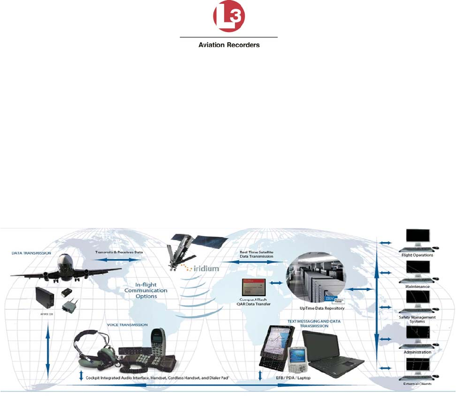
Airbus Iridium SATCOM System
165E5733-00 L-3 Aviation Recorders Proprietary
Issue, Rev. 02
21 January 2014
Page 16
2. DESCRIPTION AND OPERATION
This section describes the system operation and architecture.
2.1 System Overview
The Airbus Iridium SATCOM System provides multiple voice and data communications functions in
the aircraft. The Automated Flight Information Reporting System (AFIRS) provides a satellite voice
and data communications (SATCOM) link with the Public Switched Telephone Network (PSTN) via
the Iridium® satellite network. The system uses a standard ARINC 741/761 SATCOM interface to the
flight crew’s Audio Integrating System and ARINC 739A Multi-Purpose Control and Display Units
(MCDUs) in the cockpit, as well as providing 3-extension Public Branch Exchange (PBX) capability for
up to 2 handsets in the cabin.
Figure 2-1 – Airbus Iridium SATCOM System Operational Concept
The Airbus Iridium SATCOM System provides a dedicated safety-services data channel with the
capability to send and receive standard ACARS messages between the aircraft’s Air Traffic Service
Unit (ATSU) and a safety-services certified terrestrial service provider.
2.2 System Architecture
The Airbus Iridium SATCOM System consists of modular avionics components that can be tailored to
meet customer needs. The core system components are the Satellite Data Unit (SDU), the SDU
Configuration Module (SCM), and the Iridium Antenna (see Figure 2-2). Optional components include
Cabin Handset(s) (Wired or Cordless).
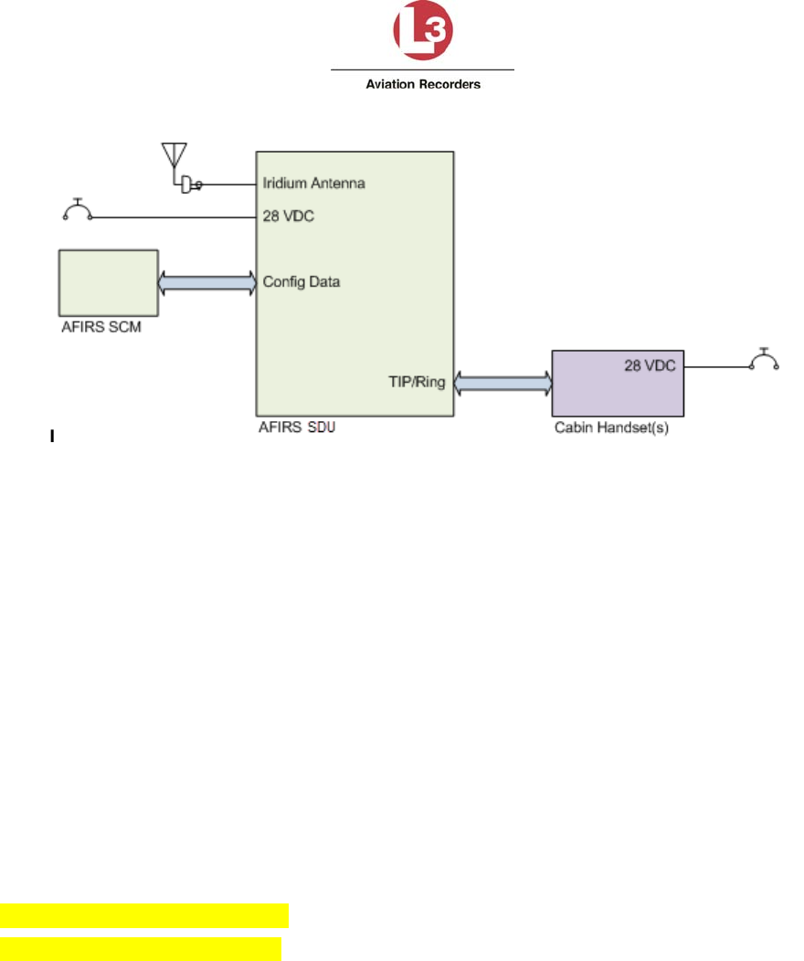
Airbus Iridium SATCOM System
165E5733-00 L-3 Aviation Recorders Proprietary
Issue, Rev. 02
21 January 2014
Page 17
Figure 2-2 – Airbus Iridium SATCOM System Block Diagram
2.3 External System Interfaces
The Airbus Iridium SATCOM System has a number of external interfaces, which are listed below and
described in detail in this section.
Audio System Interface (1)
ARINC 429 Transmitters (6) and Receivers (16)
RS-232/422 Serial Ports (4)
Ethernet Ports (4)
Discrete Outputs (8) and Inputs (16)
Iridium Antenna (1)
User Media Interfaces – SIM (1), CF (1)
Maintenance Interfaces – Ethernet (1)
Voice Modem – Iridium 9523
Data Modem – Iridium 9602
Figure 2-3 illustrates the interfaces that the Airbus Iridium SATCOM System provides to external
aircraft systems or to the user.
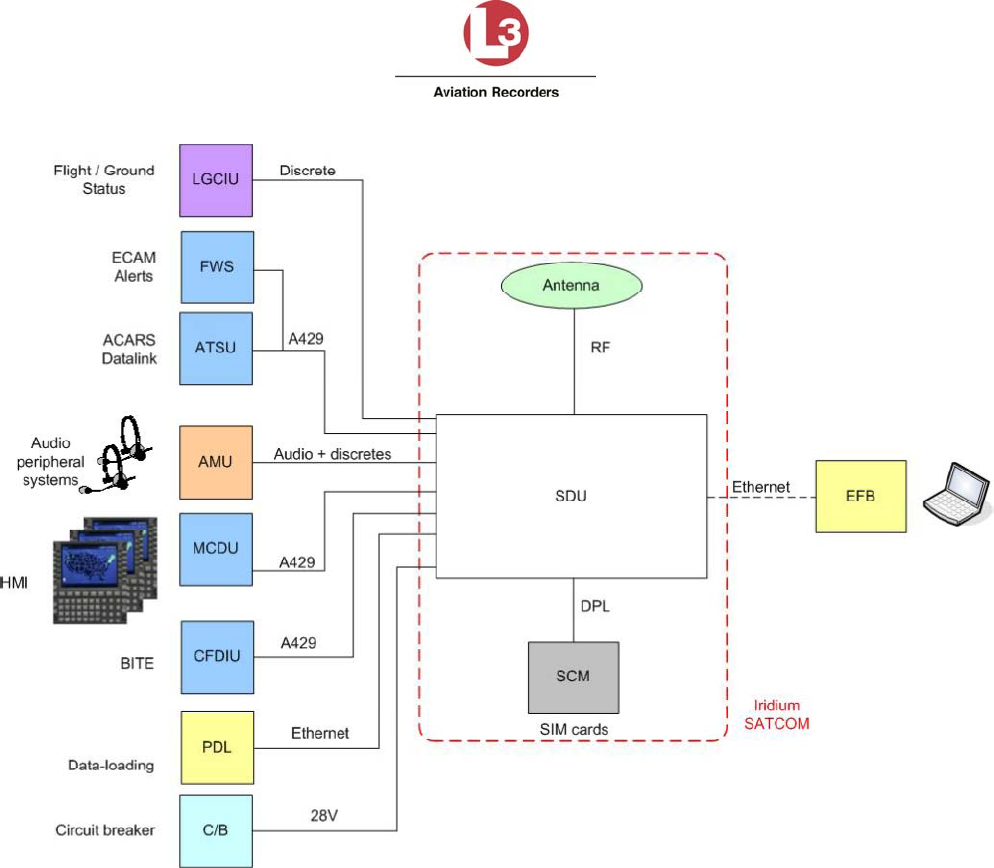
Airbus Iridium SATCOM System
165E5733-00 L-3 Aviation Recorders Proprietary
Issue, Rev. 02
21 January 2014
Page 18
Figure 2-3 – Airbus Iridium SATCOM System External Interfaces
Audio System Interface (1)
This interface consists of a Microphone Input to the SDU and an Interphone Output from the SDU
to connect to a standard (DO-214) Audio Integrating System (e.g. Audio Panel) in the aircraft.
Software selectable discrete inputs and outputs can be configured to support this interface (e.g.
Mic On, Chime, Chime Reset, End Call functions).
ARINC 429 Transmitters (6) and Receivers (16)
These interfaces can be software-configured to connect to various aircraft systems to support both
the display and control functions of the Airbus Iridium SATCOM System. Typical interfaced
systems include MCDUs, ACARS ATSUs, Airbus Centralized Fault Display Systems (CFDS), etc.

Airbus Iridium SATCOM System
165E5733-00 L-3 Aviation Recorders Proprietary
Issue, Rev. 02
21 January 2014
Page 19
RS-232/422 Serial Ports (4)
These interfaces can be software-configured to connect to different aircraft systems. Typical
interfaced systems include EFB, Global Positioning System (GPS), etc.
Ethernet Ports (4)
These interfaces can be used to connect to several different systems. Typical interfaced systems
include EFB, CFDS, etc. One of these ports can also be used to provide a remote maintenance
port interface (e.g. in the flight compartment).
Discrete Outputs (8) and Inputs (16)
Discrete inputs and outputs can be used to provide or supplement various flight crew control and
display interactions, particularly for voice functions. Discrete inputs can also be used to determine
the states of various aircraft systems when this information is not available on a databus (e.g.
Weight-on-Wheels, Doors Closed, etc.).
Iridium Antenna (1)
An antenna mounted on the top of the fuselage is used to communicate with both the Iridium
satellite network and the GPS satellite network.
User Media Interfaces – SIM (1), CF (1)
There are two types of media available for the user to insert or remove from the Airbus Iridium
SATCOM System. The SCM contains a user accessible Subscriber Identity Module (SIM) card
slot for storage of the Iridium communications management information. The SDU contains a
front panel accessible Compact Flash (CF).
Maintenance Interfaces – Ethernet (1)
An RJ45 jack on the front panel provides Maintenance Port access using an Ethernet connection.
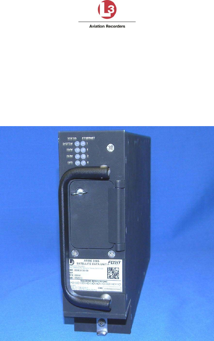
Airbus Iridium SATCOM System
165E5733-00 L-3 Aviation Recorders Proprietary
Issue, Rev. 02
21 January 2014
Page 20
3. EQUIPMENT SPECIFICATIONS
This section describes the mechanical and environmental specifications of the components of the
Airbus Iridium SATCOM System.
3.1 Satellite Data Unit (SDU)
This section describes the mechanical and environmental specifications of the components of the
Satellite Data Unit (SDU) – see Figure 3-1.
Figure 3-1 – Airbus Iridium SATCOM System Satellite Data Unit (SDU).
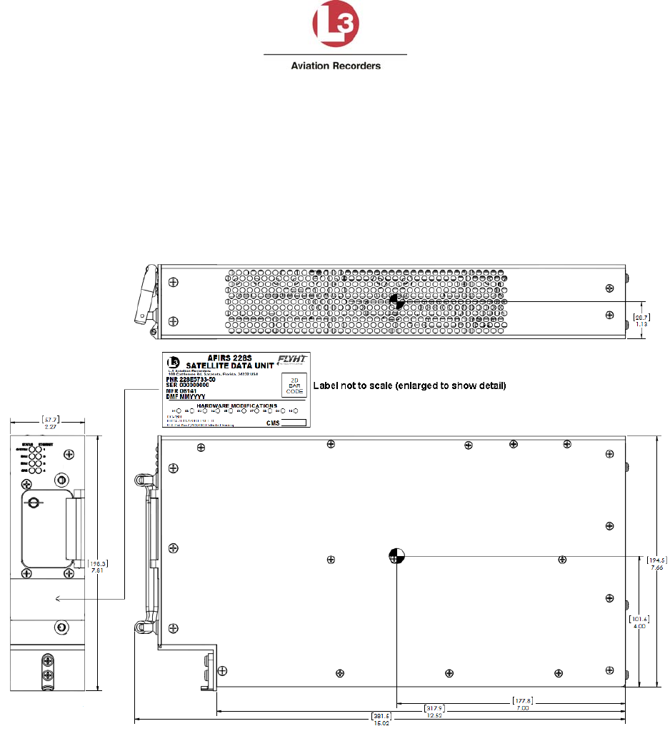
Airbus Iridium SATCOM System
165E5733-00 L-3 Aviation Recorders Proprietary
Issue, Rev. 02
21 January 2014
Page 21
3.1.1 General
The SDU is housed in an ARINC 600 2MCU enclosure, which is designed to be mounted in a
standard ARINC 600 mounting tray. See Figure 3-2 for an outline of this component.
Figure 3-2 – SDU Outline Drawing (dimensions in [millimeters] and inches)
3.1.2 Mechanical Specifications
Dimensions: 7.81” x 2.27” x 15.02” (198.3mm x 57.7mm x 381.5mm)
(See Figure 3-2)
Weight: 7.7 lbs. (3.49 kg) Max.
Material/Finish: Aluminum Alloy with Black Polyurethane Finish
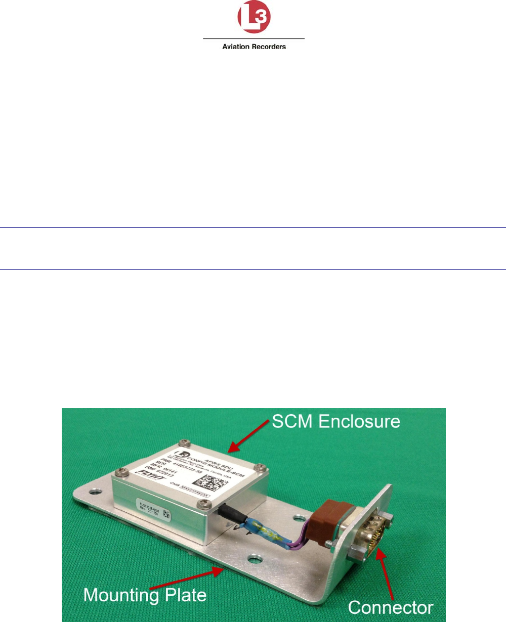
Airbus Iridium SATCOM System
165E5733-00 L-3 Aviation Recorders Proprietary
Issue, Rev. 02
21 January 2014
Page 22
Mounting: ARINC 600 2MCU Mounting Tray
Rear Mating Connector: Size 2 ARINC 600 Receptacle
Radiall P/N: NSXN2P201S0004
Maintenance Connector: RJ45 (8P8C) Modular Connector Jack
Flash Card: CompactFlash® (Type I or Type II)
3.1.3 Environmental Specifications – Airbus Iridium SATCOM System
Refer to Appendix C – Environmental Qualification Forms for environmental testing conditions,
categories and descriptions of the conducted tests of the SDU.
Note:
DO-160G Categories for the Airbus Iridium SATCOM System are as specified by the design.
Qualification tests on the Airbus Iridium SATCOM System SDU have not been completed to date.
3.2 SDU Configuration Module (SCM)
This section describes the mechanical and environmental specifications of the components of the
SDU Configuration Module (SCM) – see Figure 3-3.
3.2.1 General
The SCM is housed in a small enclosure, which is designed to be mounted within 24” of the SDU rear
connector.
Figure 3-3 – Airbus Iridium SATCOM System SDU Configuration Module (SCM)
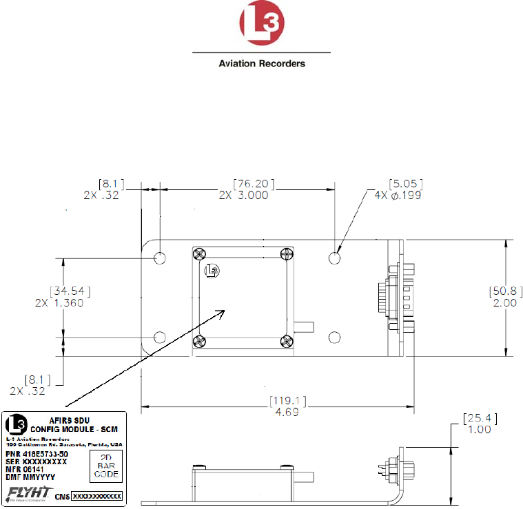
Airbus Iridium SATCOM System
165E5733-00 L-3 Aviation Recorders Proprietary
Issue, Rev. 02
21 January 2014
Page 23
Typically, the SCM will be mounted on or near the ARINC 600 mounting tray used for the SDU. See
Figure 3-4 for an outline of this component.
Figure 3-4 – SCM Outline Drawing (dimensions in [millimeters] and inches)
3.2.2 Mechanical Specifications
Dimensions: 1.00” x 2.00” x 4.69” (25.4mm x 50.8mm x 119.1mm)
Weight: 0.4 lbs. (0.18 kg) Max.
Material/Finish: Aluminum alloy with clear chromate per MIL-DTL-5541, Type II,
Class 3 on all surfaces
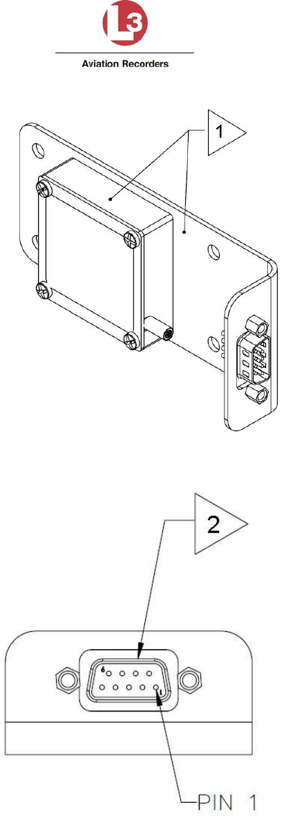
Airbus Iridium SATCOM System
165E5733-00 L-3 Aviation Recorders Proprietary
Issue, Rev. 02
21 January 2014
Page 24
Figure 3-5 – SCM Oblique View (Note 1: Resistance between mounting plate and module not to exceed
20 milli-ohms. Also, resistance between mounting plate and aircraft structure not to exceed 20 milli-ohms.)
Figure 3-6 – SCM Connector View Showing Location of Pin 1 (Note 2: Connector is a 9-pin D-Sub,
P/N ABS1145A09P03B.)
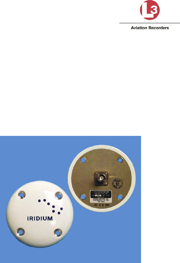
Airbus Iridium SATCOM System
165E5733-00 L-3 Aviation Recorders Proprietary
Issue, Rev. 02
21 January 2014
Page 25
3.2.3 Environmental Specifications
Refer to Appendix C – Environmental Qualification Forms for environmental testing conditions,
categories and descriptions of the conducted tests of the SCM.
3.3 Airbus Iridium SATCOM System Satellite Antenna
The antenna is a Commercial Off the Shelf (COTS) unit that is mounted on the top of the aircraft’s
fuselage – see Figure 3-7. It provides satellite connectivity for both the GPS and Iridium satellite
systems.
Figure 3-7 – Airbus Iridium SATCOM System Antenna
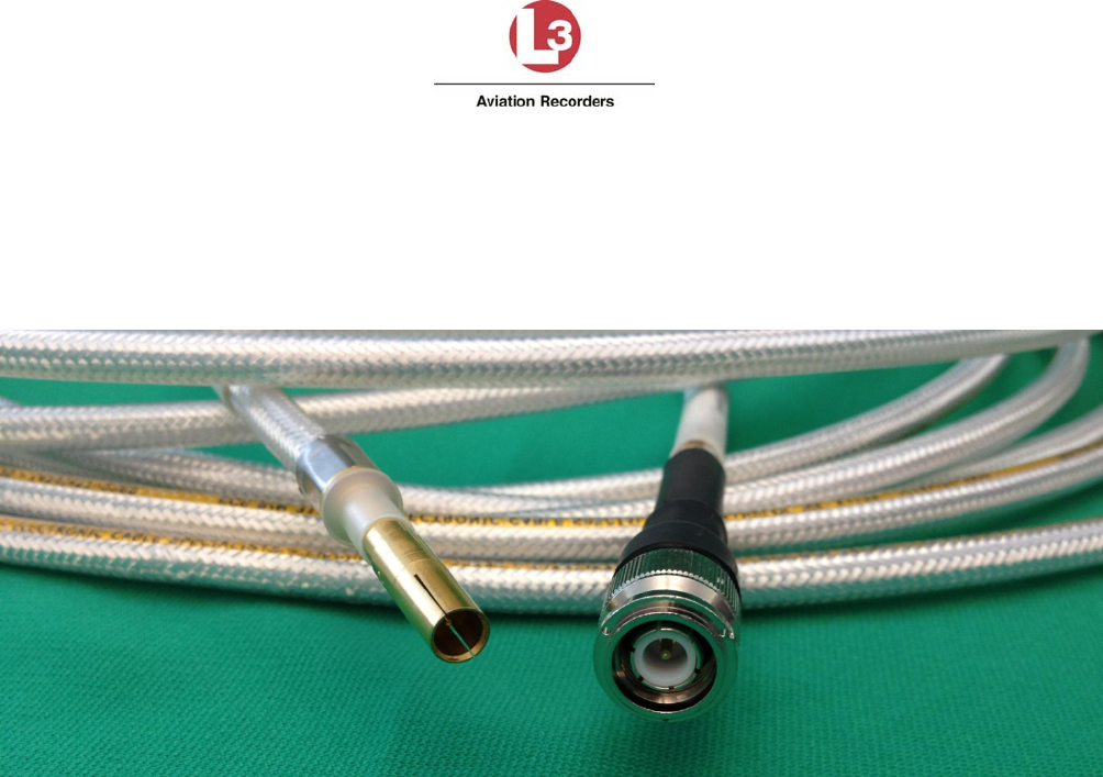
Airbus Iridium SATCOM System
165E5733-00 L-3 Aviation Recorders Proprietary
Issue, Rev. 02
21 January 2014
Page 26
3.4 Antenna Coaxial Cable
For details on the selection and installation of the antenna coaxial cable, please see Section 4.3.4,
which provides recommended coaxial cable types to be used which meet the Airbus Iridium SATCOM
System requirements. Figure 3-8 illustrates the Iridium antenna coaxial cable and connectors.
Figure 3-8 – Iridium Antenna Coaxial Cable and Connectors
3.5 Interface Specifications
This section describes the interface specifications of the Airbus Iridium SATCOM System
components.
Airbus Iridium SATCOM System
165E5733-00 L-3 Aviation Recorders Proprietary
Issue, Rev. 02
21 January 2014
Page 27
SDU Rear Connector (J1)
Table 3-1 – J1A Top Plug (TP) Insert
A B C D E F G H J
K
1 Ethernet
1A
Tx+
Ethernet
1A
Rx+
O O
Ethernet
2B
Tx+
Ethernet
2B
Rx+
O O
Ethernet
3B
Tx+
Ethernet
3B
Rx+
2 Ethernet
1A
Rx-
Ethernet
1A
Tx-
O
Ethernet
2B
Rx-
Ethernet
2B
Tx-
O O
Ethernet
3B
Rx-
Ethernet
3B
Tx-
3 O O O O O O O O O O
4 O O O O O O O O O O
5 Ethernet
4B
Tx+
Ethernet
4B
Rx+
O O O O O O O O
6 Ethernet
4B
Rx-
Ethernet
4B
Tx-
O O O O O O O O
7 O O O O O O O O O O
8 O O O O O O O O O O
9 O O O O O O O O O O
10 O O O O O O O O O O
11 O O O O O O O O O O
12 O O O O O O O O O O
13 O O O O O O O O O O
14 O O O O O O O O O O
15 O O O O O O O O O O
Airbus Iridium SATCOM System
165E5733-00 L-3 Aviation Recorders Proprietary
Issue, Rev. 02
21 January 2014
Page 28
Table 3-2 – J1B Middle Plug (MP) Insert
A B C D E F G H J
K
1 O O O O O O
No. 1
A429Rx
A
No. 1
A429Rx
B
No. 1
A429Tx
A
No. 1
A429Tx
B
2 Ext. 1
Mic Audio
Hi
Ext. 1
Mic Audio
Lo
Ext. 1
Audio Out
Hi
Ext. 1
Audio Out
Lo
O O O O O O
3 O O
No. 2
A429Rx
A
No. 2
A429Rx
B
No. 3
A429Rx
A
No. 3
A429Rx
B
No. 4
A429Rx
A
No. 4
A429Rx
B
No. 2
A429Tx
A
No. 2
A429Tx
B
4
O
O O O O O O O
SCM
Power
SCM
Ground
5 No. 1
Discrete
Output
LGCIU 1
Discrete
Input
No. 2
Discrete
Input
No. 3
Discrete
Input
No. 4
Discrete
Input
No. 5
Discrete
Input
No. 6
Discrete
Input
No. 7
Discrete
Input
SCM
Data
SCM
Clock
6 No. 5
A429Rx
A
No. 5
A429Rx
B
No. 6
A429Rx
A
No. 6
A429Rx
B
No. 7
A429Rx
A
No. 7
A429Rx
B
No. 8
A429Rx
A
No. 8
A429Rx
B
No. 9
A429Rx
A
No. 9
A429Rx
B
7 No. 10
A429Rx
A
No. 10
A429Rx
B
No. 3
A429Tx
A
No. 3
A429Tx
B
No. 4
A429Tx
A
No. 4
A429Tx
B
No. 11
A429Rx
A
No. 11
A429Rx
B
No. 1
RS232
Com
No. 4
RS232
Com
8 No. 8
Discrete
Input
No. 2
Discrete
Output
No. 12
A429Rx
A
No. 12
A429Rx
B
No. 3
Discrete
Output
No. 9
Discrete
Input
No. 4
Discrete
Output
No. 10
Discrete
Input
No. 13
A429Rx
A
No. 13
A429Rx
B
9 No. 2
RS232
Com
No. 3
RS232
Com
No. 5
A429Tx
A
No. 5
A429Tx
B
No. 1
RS422Tx-
RS232TXD
No. 1
RS422Tx+
RS232RTS
No. 1
RS422Rx+
RS232RXD
No. 1
RS422Rx-
RS232CTS
No. 2
RS422Tx-
RS232TXD
No. 2
RS422Tx+
RS232RTS
10 No. 2
RS422Rx+
RS232RXD
No. 2
RS422Rx-
RS232CTS
No. 3
RS422Tx-
RS232TXD
No. 3
RS422Tx+
RS232RTS
No. 3
RS422Rx+
RS232RXD
No. 3
RS422Rx-
RS232CTS
No. 4
RS422Tx-
RS232TXD
No. 4
RS422Tx+
RS232RTS
No. 4
RS422Rx+
RS232RXD
No. 4
RS422Rx-
RS232CTS
11 No. 11
Discrete
Input
No. 12
Discrete
Input
No. 13
Discrete
Input
No. 14
Discrete
Input
No. 15
Discrete
Input
LGCIU
HPP
No. 5
Discrete
Output
No. 6
Discrete
Output
No. 7
Discrete
Output
No. 8
Discrete
Output
12 No. 14
A429Rx
A
No. 14
A429Rx
B
No. 6
A429Tx
A
No. 6
A429Tx
B
A717Rx
A
A717Rx
B
No. 15
A429Rx
A
No. 15
A429Rx
B
No. 16
A429Rx
A
No. 16
A429Rx
B
13 Fault
Output
N/C
Fault
Output
N/O
O O O O O O O O
14 O Chime
Output O O O O O O O O
15 O O O O O O
Phone
Ext. 2
Tip
Phone
Ext. 2
Ring
Phone
Ext. 3
Tip
Phone
Ext. 3
Ring
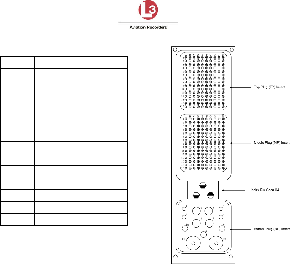
Airbus Iridium SATCOM System
165E5733-00 L-3 Aviation Recorders Proprietary
Issue, Rev. 02
21 January 2014
Page 29
Table 3-3 – J1C Bottom Plug (BP) Insert
Pin Size Description
1 20 Not Used
2 12 Primary 28 VDC Power Input
3 12 Power Ground
4 20 Not Used
5 20 Not Used
6 20 Not Used
7 12 Not Used
8 12 Chassis Ground
9 16 Not Used
10 16 Not Used
11 16 Not Used
12 5 Not Used
13 5 Iridium/GPS Antenna
Figure 3-9 – SDU Connector Map
3.5.1 Power Input
The Airbus Iridium SATCOM System is powered by +28 VDC.
3.5.2 Chassis Ground
For redundant chassis ground connection only. Not to be used as a normal current carrying
conductor.
Quantity: 1
Format: DC Chassis Ground

Airbus Iridium SATCOM System
165E5733-00 L-3 Aviation Recorders Proprietary
Issue, Rev. 02
21 January 2014
Page 30
3.5.3 ARINC 429 Digital Serial Bus Input
Quantity: 16
Format: DITS, ARINC 429 Low or high speed
Low Speed Data Rate: 12.5 Kbps ± 1%
High Speed Data Rate: 100 Kbps ± 1%
SSM/SDI/Data Definition: Software Selectable Protocols
3.5.4 ARINC 429 Digital Serial Bus Output
Quantity: 6
Format: DITS, ARINC 429 Low or high speed
Low Speed Data Rate: 12.5 Kbps ± 1%
High Speed Data Rate: 100 Kbps ± 1%
SSM/SDI/Data Definition: Software Selectable Protocols
3.5.5 Ethernet
Quantity: 4
Format: 802.3 10BASE-T/100BASE-TX, half- and full-duplex
modes (auto-negotiated)
ARINC 664P2 Physical Layer
3.5.6 Discrete Inputs
Quantity: 16 Configurable
Input Impedance: >10 kΩ
Fault Current: <15 mA
DIN+ Voltage Range: Logic High: 7.0 – 36.0 VDC
Logic Low: 0 – 3.5 VDC
Pulse Width (Min): 100 ms
3.5.6.1 Configurable Inputs
Each configurable discrete input is individually software-configurable for the following:
Signal Level: Open-Ground (Negative-Seeking) or Open-28V (Positive-Seeking)
Logic Assignment: Active Low or Active High
Function: Selected from list.
Refer to §6.10 for additional information on use of configurable inputs.

Airbus Iridium SATCOM System
165E5733-00 L-3 Aviation Recorders Proprietary
Issue, Rev. 02
21 January 2014
Page 31
3.5.7 Discrete Outputs
Each discrete output transitions between an ‘Open Circuit’ (high-impedance-to-ground) and a ‘Closed
Circuit’ (low-impedance-to-ground) state to indicate a change in output logic.
Quantity: 8 Configurable
‘Open Circuit’ Impedance: >100 kΩ
‘Open Circuit’ Voltage (Max.): 36 VDC
‘Closed Circuit’ Current Limit (Min.): 500 mA
Voltage Across ‘Closed Circuit’: <1.25 V
3.5.7.1 Configurable Outputs
The Discrete Outputs use ‘Open-Closed’ signal levels, where the output is either high-impedance to
ground (Open) or low-impedance to ground (Closed). Each configurable discrete output is individually
software-configurable for the following:
Logic Assignment: Active Low (Closed) or Active High (Open)
Function: Selected from list.
Refer to §6.11 for additional information on use of configurable outputs.
3.5.8 Two-Wire Phone
Quantity: 2
Format: Standard 2-Wire Tip and Ring Loop
Loop Battery: 48 ±4 VDC
Ring Signal: 20 Hz ±10%, 90 ±10 VAC RMS
Hook Flash: <700 ms
Load Impedance (Nom.): 600 Ω
Polarity Sensitivity: None
Audio Band Pass: 300 – 3400 Hz
3.5.9 Microphone Input
Quantity: 1
Format: Standard DO-214 Microphone Input
Dynamic Range: 20 mV to 1.5 V RMS
Input Impedance: 150 Ω ± 20%
Mic. Bias (No Load): 16 ± 0.5 V
Mic. Bias Ripple: <1 mV RMS in the 300 – 3400 Hz band
Airbus Iridium SATCOM System
165E5733-00 L-3 Aviation Recorders Proprietary
Issue, Rev. 02
21 January 2014
Page 32
Sidetone: Provided by System to Interphone Output
Sidetone Level: Software Configurable
Audio Band Pass: 300 – 3400 Hz
3.5.10 Iridium / GPS Antenna
Coaxial Cable Insertion Loss (Max.): 3 dB @ 1626.5 MHz
3.6 SDU Maintenance Connector (J2)
The Airbus Iridium SATCOM System SDU provides an RJ-45 Maintenance Port connector on the
front panel which provides for Ethernet connection to Ground Service Equipment (GSE) e.g. a laptop
or Personal Computer with a standard web browser.
3.7 SDU Configuration Module (SCM)
The SCM and antenna connect directly to the SDU. The SDU is the heart of the system and provides
all of the interfaces to other aircraft systems.
3.8 ARINC 429 Receiver Protocols
Table 3-4 – ARINC 429 Receiver Protocols – ATSU/FWC
Source: ATSU / FWC Speed: High
(Configurable)
Label Parameter Format Transmit Rate
172 ATSU Identifier Word BCD 1 s
214 ATSU ICAO Address Word 1 Boolean
word
200 ms
216 ATSU ICAO Address Word 2 Boolean
word
200 ms
270 ATSU Status Word and Monitoring Boolean
word
600 ms
307 SDU SAL HYB
377 ATSU Equipment Identifier BCD 1 s
ARINC
618
Block
Uplink
BOP (GFI=Eh) ISO 5 N/A
ARINC
618
Block
Downlink
BOP (GFI=Eh) ISO 5 N/A
Airbus Iridium SATCOM System
165E5733-00 L-3 Aviation Recorders Proprietary
Issue, Rev. 02
21 January 2014
Page 33
Table 3-5 – ARINC 429 Receiver Protocols – CFDS
Source: Airbus CFDS Speed: Low
(Configurable)
Label Parameter Format Transmit Rate
125 Time (UTC) BCD 1 s
126 Flight Phases BNR 1 s
155 Aircraft Configuration (Printer, ACARS, etc.) Discrete
word
1 s
156 Aircraft Type Discrete
word
1 s
157 Aircraft Configuration (ATSU2, ATSU1) Discrete
word
1 s
227 CFDS BITE Command ISO 5 120 ms
233 Flight Number 1, 2 ISO 5 4 s
234 Flight Number 3, 4 ISO 5 4 s
235 Flight Number 5, 6 ISO 5 4 s
236 Flight Number 7, 8 ISO 5 4 s
260 BCD Date YY/MM/DD BCD 1 s
301 Aircraft Identification 1,2,3 (ORT parameter) ISO 5 4 s
302 Aircraft Identification 4,5,6 (ORT parameter) ISO 5 4 s
303 Aircraft Identification 7,8,9 (ORT parameter) ISO 5 4 s
304 Fleet Identification, Aircraft Type ISO 5 4 s
Table 3-6 – ARINC 429 Receiver Protocols – MCDU
Source: ARINC 739A MCDU Speed: Low
(Configurable)
Label Parameter Format Transmit Rate
377 MCDU Identifier BCD 1 s
270 Discrete Word #1 Discrete
word
1 s
350 Maintenance Word #1 Discrete
word
1 s
307 SDU SAL HYB
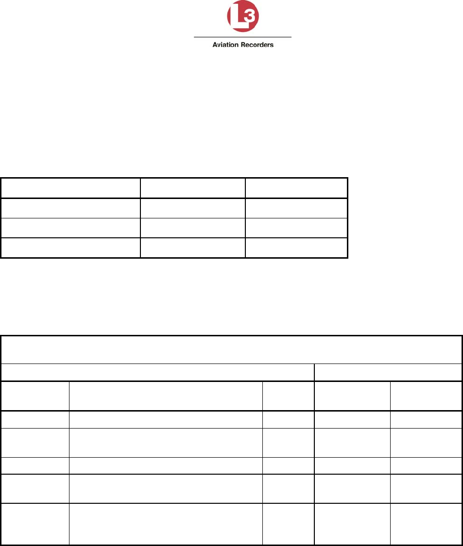
Airbus Iridium SATCOM System
165E5733-00 L-3 Aviation Recorders Proprietary
Issue, Rev. 02
21 January 2014
Page 34
3.9 ARINC 429 Receiver Activity Status
Defines the criteria the Airbus Iridium SATCOM System uses for determining whether a receiver port
is active. A bus is generally declared active when 4 consecutive words at the specified rate are
received, and declared inactive when 4 consecutive samples fail.
Table 3-7 – ARINC 429 Receiver Port Monitoring
Receiver Activity Label Min. Update Rate
ATSU / FWC 270 1 Hz
ARINC 739A MCDU 270 / 377 1 Hz
Airbus CFDS 125 / 260 1 Hz
3.10 ARINC 429 Transmitter Protocols
Table 3-8 – ARINC 429 Transmitter Protocols SDU – ATSU/FWC
3.10.1 From SDU to ATSU / FWC
Destination: ATSU / FWC Speed: High (Configurable)
Label Parameter Format Transmit
Rate Update Rate
172 SDU Identifier BCD 1 s –
270 SDU Status Word and Monitoring Boolean
word
1 s -
304 ATSU SAL HYB
ARINC 618
Block Uplink
BOP (GFI=Eh) ISO 5 N/A -
ARINC 618
Block
Downlink
BOP (GFI=Eh) ISO 5 N/A -
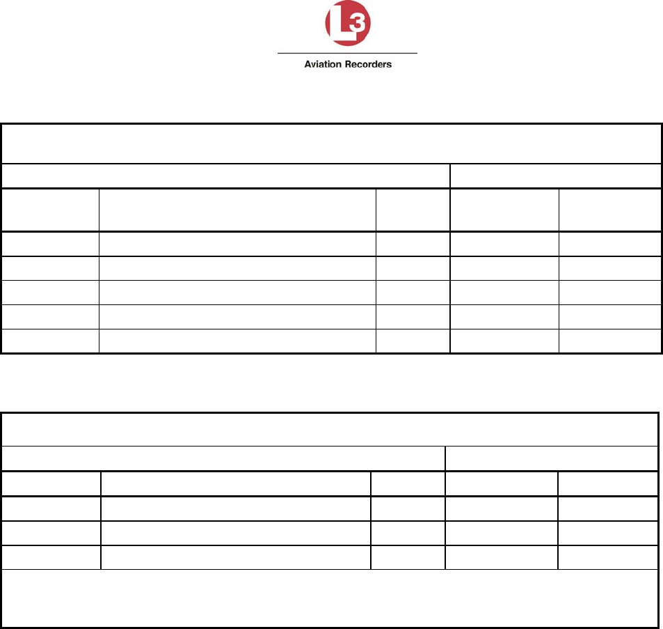
Airbus Iridium SATCOM System
165E5733-00 L-3 Aviation Recorders Proprietary
Issue, Rev. 02
21 January 2014
Page 35
Table 3-9 – ARINC 429 Transmitter Protocols SDU – MCDU
3.10.2 From SDU to MCDU
Destination: ARINC 739A MCDU Speed: Low (Configurable)
Label Parameter Format Transmit
Rate Update Rate
172 Subsystem Identifier BCD 1 s –
377 Equipment Identifier BCD 1 s –
220 MCDU Address Label for MCDU#1
221 MCDU Address Label for MCDU#2
222 MCDU Address Label for MCDU#3
Table 3-10 – ARINC 429 Transmitter Protocols SDU – CFDS
3.10.3 From SDU to Airbus CFDS
Destination: Airbus CFDS Speed: Low (Configurable)
Label Parameter Format Transmit Rate Update Rate
354 LRU Identification (PN, SN) ISO 5 500 ms –
3561 Fault Status ISO 5 200 ms -
377 ARINC 429 Equipment Identifier BCD 1 s –
Notes:
1. Label 356 is only transmitted when the system is in Operational or Maintenance mode and there are
no active failures or faults.
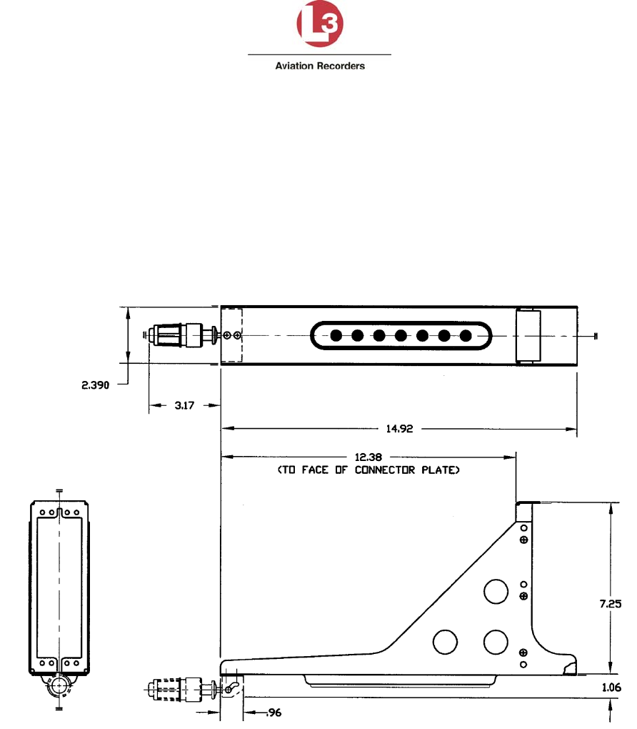
Airbus Iridium SATCOM System
165E5733-00 L-3 Aviation Recorders Proprietary
Issue, Rev. 02
21 January 2014
Page 36
4. INSTALLATION CONSIDERATIONS
This section provides information on the installation considerations for each of the Airbus Iridium
SATCOM System components.
4.1 Satellite Data Unit (SDU)
The SDU is housed in an ARINC 600 2MCU enclosure, which is designed to be mounted in a
standard ARINC 600 mounting tray. Figure 4-1 shows a typical ARINC 600 2MCU tray used for the
SDU.
Figure 4-1 – 2MCU Mounting Tray
While the SDU does not require forced-air cooling, every attempt should be made to place the SDU in
a benign and well-ventilated environment. Placing the SDU on a plenum shelf in the Electronics Bay
of the aircraft and using a mounting tray that provides cooling air to the SDU is preferred.
The SDU tray should be electrically bonded to the airframe (<20 milliohms). It is recommended that
the SDU be located where easy front panel access is available to facilitate replacing the flash card or
connecting to the Maintenance Port.

Airbus Iridium SATCOM System
165E5733-00 L-3 Aviation Recorders Proprietary
Issue, Rev. 02
21 January 2014
Page 37
4.2 SDU Configuration Module (SCM)
The SCM can be mounted on or near the SDU tray within 24 inches of the SDU rear connector. The
SCM should be electrically bonded to the airframe (<20 milliohms). It is recommended that the SCM
be located to provide easy access to the cover if ever the SIM card requires replacement. Refer to
Figure 3-4 for the SCM mounting footprint.
4.3 Iridium Antenna System
The Airbus Iridium SATCOM System has a single combined Iridium/GPS RF connection on the rear
interface connector, which is to be connected to a single combined Iridium/GPS Antenna. The
antenna system is comprised of all the components from the rear interface connector up to and
including the antenna. The total gain of the antenna system must be greater than 0 dB at 1626.5 MHz
(measured at the antenna zenith).
Most Iridium antennas have a gain of +3 dBic at the zenith; therefore the maximum attenuation in the
rest of the antenna system must be less than 3 dB. If an antenna with a different gain is selected, the
maximum loss of the rest of the antenna system must be adjusted accordingly.
4.3.1 Antenna
Iridium SATCOM System Antenna: This is a passive antenna designed to cover the frequency range
from 1565 MHz to 1626.5 MHz for Iridium transmit / receive operations and GPS reception. It is a
low-profile, circular device that can be mounted directly to the aircraft fuselage. This antenna
connects to the Iridium SDU through a coaxial cable – see Figure 3-8 Figure 3-7.
The antenna specifications are listed below:
Weight (Typical)
0.170 kg (6 oz.)
Overall Dimensions (Typical)
Height: 16.8 mm (0.66 inches)
Diameter: 89 mm (3.5 inches)
Manufacturer’s Specification Reference Number
Drawing 009E5733-00, Revision – Iridium Antenna – Passive, 1565 – 1626.5 MHz,
RHCP – see Figure 4-2.
Iridium SATCOM System Supplier Equipment Specification,
Document No. 905-E5750-07, Revision –
Environmental Specifications
The Iridium SATCOM System antenna meets the environmental requirements of RTCA DO-
262A where applicable as referenced in Document No. 905-E5809-42, Revision A.
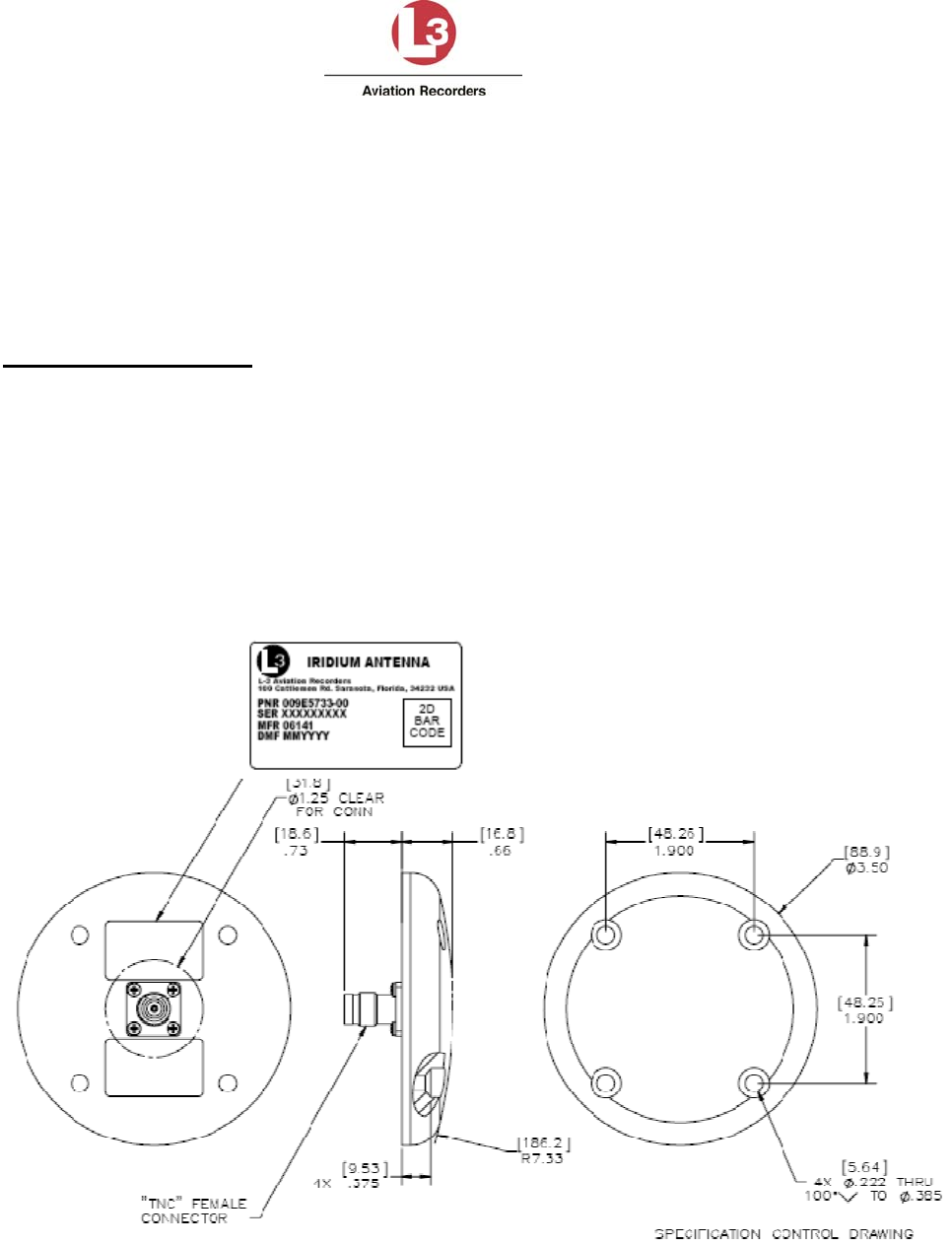
Airbus Iridium SATCOM System
165E5733-00 L-3 Aviation Recorders Proprietary
Issue, Rev. 02
21 January 2014
Page 38
Testing was performed to DO-160F, MIL-STD-810, EN-60068, ISO-2669, and the applicable
ABDs unless otherwise noted.
Temperature: -55° C (-67° F); to +85° C (+185° F)
Altitude: -100 to +55,000 FT
Vibration: 10 G’s (DO-160D/E F2-AB)
Electrical Specifications
Frequency: 1616.0 – 1625.5 MHz
VSWR: ≤ 1.5:1
Impedance: 50-Ohms
Polarization: RHCP
Axial Ratio: ≤ 3.0 db @ zenith
Power Handling: 60 Watts CW
Figure 4-2 - Iridium Antenna, Outline and Dimensions
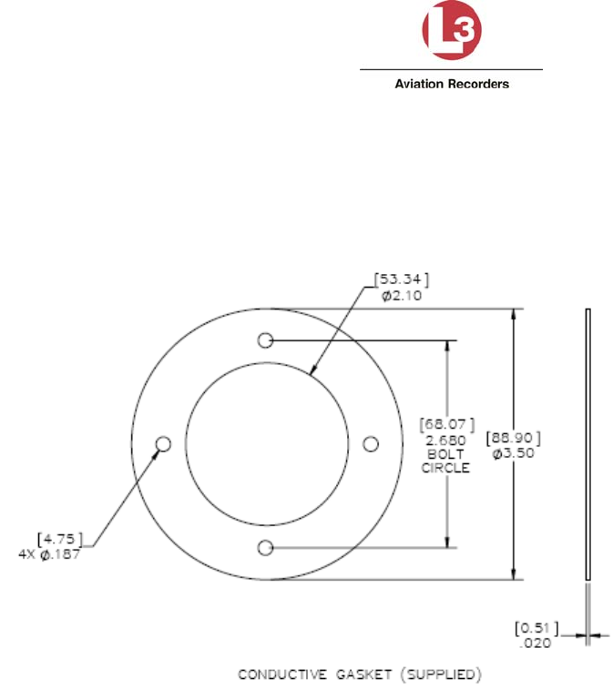
Airbus Iridium SATCOM System
165E5733-00 L-3 Aviation Recorders Proprietary
Issue, Rev. 02
21 January 2014
Page 39
4.3.2 Antenna Mounting
A .020 Thick Conductive Gasket is provided. L-3 recommends using (4) screws, MS24693-C274 for
mounting the Airbus Iridium Antenna – see Figure 4-3.
Figure 4-3 - Iridium Antenna, Gasket
4.3.3 Coaxial Cable
Iridium SATCOM System Coaxial Cable: This is an RF Cable designed to cover the frequency range
from 1565 MHz to 1626.5 MHz for Iridium transmit / receive operations and GPS reception. It is a
low-loss, aircraft-grade cable that will be mounted in the aircraft fuselage. This cable provides the
interconnection between the Iridium SATCOM System Satellite Data Unit and the Iridium Antenna.
The Coaxial Cable has an ARINC Size 5 coaxial contact installed on one end and a TNC male
connector installed on the other.
There are three possible lengths for this Coaxial Cable. They are designated by the last two digits of
the part number (01, 02 or 03) as listed below:
024E5733-01
024E5733-02
024E5733-03
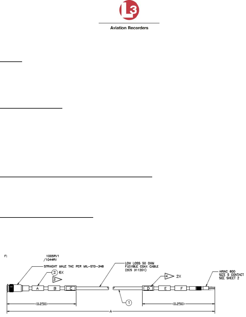
Airbus Iridium SATCOM System
165E5733-00 L-3 Aviation Recorders Proprietary
Issue, Rev. 02
21 January 2014
Page 40
The antenna coaxial specifications are listed below:
Weight (Typical)
024E5733-01 - 1.633 kg (57.6 oz)
024E5733-02 – 1.497 kg (52.8 oz)
024E5733-03 – 1.470 kg (51.8 oz)
Overall Dimensions (Typical)
Length:
024E5733-01 – 11.3 m (445.0 inches)
024E5733-02 – 10.2 m (402.0 inches)
024E5733-03 – 9.95 m (392.0 inches)
Diameter: 8.1 mm (0.317 inches)
Manufacturer’s Specification Reference Number
Drawing 024E5733-00, Revision B; Iridium Antenna Coax Cable – see Figure 4-4.
Iridium SATCOM System Supplier Equipment Specification,
Document No. 905-E5750-07, Revision –
Environmental Specifications
The Iridium SATCOM System Coaxial Cable meets the environmental requirements of RTCA
DO-262A where applicable as described in Document No. 905E5836-42. Testing was
performed to DO-160F, EN 4604, EN 3475, and the applicable ABDs unless otherwise noted.
Figure 4-4 – Iridium Antenna Coaxial Cable

Airbus Iridium SATCOM System
165E5733-00 L-3 Aviation Recorders Proprietary
Issue, Rev. 02
21 January 2014
Page 41
5. SATCOM INSTALLATION MATERIALS
In addition to the Airbus Iridium SATCOM System LRUs (SDU and SCM), the materials described in
this section are generally required as part of a typical Airbus Iridium SATCOM System installation.
Note:
The system integrator is responsible to ensure that all installation materials used meet the regulatory
requirements for the intended aircraft installation environment.
5.1 Required Materials
ARINC 600 2MCU mounting tray
ARINC 600 Size 2 connector, with contacts
ARINC 600 ground block, with contacts
Iridium antenna (ref.4.3.1)
Antenna coaxial cable(s) (ref. §4.3.3)
System interface wiring (ref. §6)

Airbus Iridium SATCOM System
165E5733-00 L-3 Aviation Recorders Proprietary
Issue, Rev. 02
21 January 2014
Page 42
6. SYSTEM INTERFACE WIRING
This section provides information on the system interface wiring required for the Airbus Iridium
SATCOM System.
6.1 General
All wire types and installation practices must comply with the requirements for the aircraft. Unless
otherwise noted, minimum wire size is 22 AWG for standard copper wire or 24 AWG for high strength
copper alloy wire.
Terminate all shields at ground block or ground stud on SDU tray. Keep shield drains and unshielded
conductor lengths as short as practicable (<3”).
6.2 Primary Power, Antenna, and SCM
The primary power, antenna, and SCM connections shown in Figure 6-1 are required for all Airbus
Iridium SATCOM System installations. The system will start and continue to operate whenever power
(20.5 – 32.2 VDC) is available at the Primary Power Input pin (J1C-2).
Figure 6-1 – Primary Power, Antenna, and SCM Interface
6.3 ARINC 429 Interfaces
The Airbus Iridium SATCOM System has 16 ARINC 429 receive ports and 6 ARINC 429 transmit
ports. Each port is software-configurable for high or low speed, and the receive ports are also
individually software-configurable for odd, even or no parity checking. The transmit ports always
transmit odd parity.

Airbus Iridium SATCOM System
165E5733-00 L-3 Aviation Recorders Proprietary
Issue, Rev. 02
21 January 2014
Page 43
6.3.1 Receiver Protocols
Each of the ARINC 429 receivers can be configured in software for the proper protocol of the external
aircraft system to which it is interfaced. Below is a list of the available ARINC 429 receiver protocols.
(See §3.8 for the label specifications for each receiver protocol.) Once a protocol (except “None” is
selected for any given receive port, it is no longer available for assignment to any of the other ports.
None
ACARS 1
ACARS 2
Airbus CFDS
A739 MCDU 1
A739 MCDU 2
A739 MCDU 3
When an input is not connected to an active system (e.g. no connection, or wiring provisions only are
installed), the port should be configured as “None” to avoid triggering bus inactivity faults.
6.3.2 Transmitter Protocols
Each of the ARINC 429 transmitters can be configured in software for the proper protocol of the
external aircraft system to which it is interfaced. Below is a list of the available ARINC 429 transmitter
protocols. (See §3.10 for the label specifications for each transmitter protocol.) Once a protocol
(except “None”) is selected for any given port, it is no longer available for assignment to any of the
other ports.
None
ACARS
A739 MCDU
Airbus CFDS
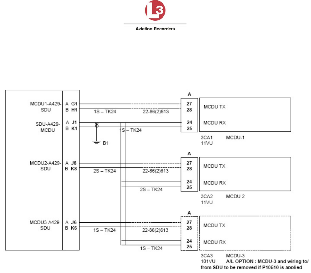
Airbus Iridium SATCOM System
165E5733-00 L-3 Aviation Recorders Proprietary
Issue, Rev. 02
21 January 2014
Page 44
6.4 MCDU
If an ARINC 739A MCDU is installed, MCDU 1 should be connected to ARINC 429 Tx 1 and ARINC
429 Rx 1. For MCDU 2 and 3, ARINC 429 Rx ports 2 and 3 are used as shown in Figure 6-2, but any
Rx port from 2 to 16 may be used.
Figure 6-2 – MCDU Interface
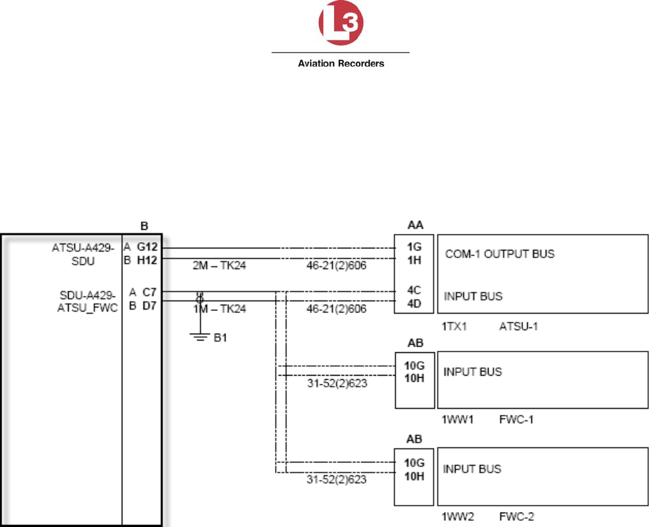
Airbus Iridium SATCOM System
165E5733-00 L-3 Aviation Recorders Proprietary
Issue, Rev. 02
21 January 2014
Page 45
6.5 ACARS ATSU
The ACARS ARINC 429 Tx interface provides safety-services data functionality for the Airbus Iridium
SATCOM System. It is recommended that if the ACARS ATSU ARINC 429 Rx connection will not be
utilized, that the wires be capped and stowed near the connectors as shown. ARINC 429 Rx port 4 is
shown in Figure 6-3, but any Rx port from 2 to 16 may be used.
Figure 6-3 – ACARS ATSU Interface
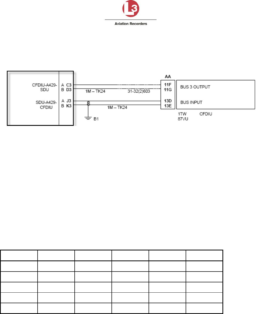
Airbus Iridium SATCOM System
165E5733-00 L-3 Aviation Recorders Proprietary
Issue, Rev. 02
21 January 2014
Page 46
6.6 CFDIU Interface
The SDU communicates with the Airbus Centralized Fault Display Interface Unit (CFDIU) over
two ARINC 429 Low Speed busses, (1) input and (1) output as shown in Figure 6-4.
Figure 6-4 – CFDIU Interface
6.7 Date, Time and Position
The Airbus Iridium SATCOM System uses date, time and position information for numerous purposes,
including information tags attached to various reports and events. Date, time and position information
is provided by the system’s internal GPS.
6.8 RS-232/422 Databus
The Airbus Iridium SATCOM System has four serial ports (transmit and receive). Each port is
software-configurable for RS-232 or RS-422 mode. The speed, data bits, parity, stop bits, and flow
control settings for each port are also software-configurable. See Figure 6-5.
Each serial port is assigned 5 pins on the rear connector. The function of these pins is dependent on
whether RS-232 or RS-422 mode is being used.
Table 6-1 – Serial Port Pin Assignments
RS-232 RS-422 Port 1 Port 2 Port 3 Port 4
TXD Tx- 9E 9J 10C 10G
RTS Tx+ 9F 9K 10D 10H
RXD Rx+ 9G 10A 10E 10J
CTS Rx- 9H 10B 10F 10K
Com Not Used 7J 9A 9B 7K
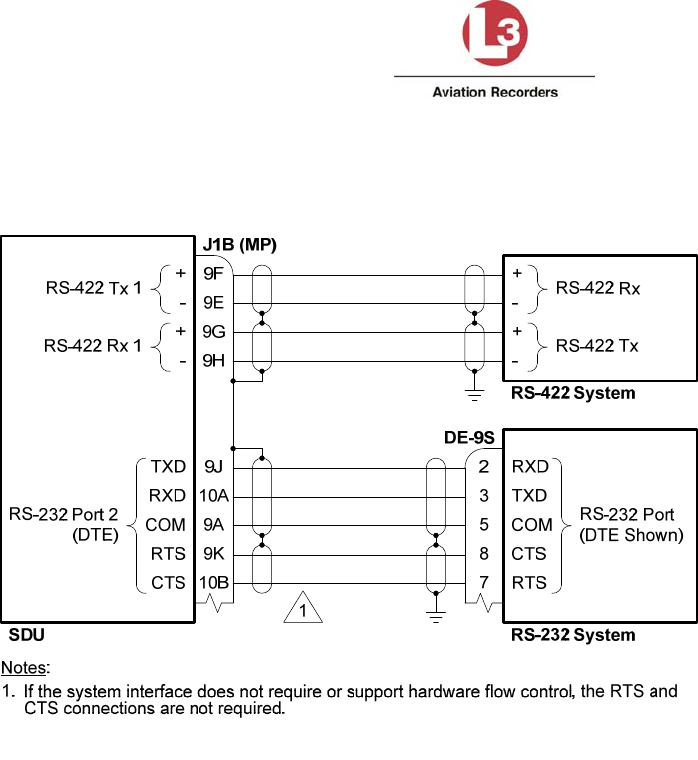
Airbus Iridium SATCOM System
165E5733-00 L-3 Aviation Recorders Proprietary
Issue, Rev. 02
21 January 2014
Page 47
When configured for RS-232 mode, the serial ports support software (Xon/Xoff) and hardware
(RTS/CTS) handshaking. If hardware handshaking is not being used, the RTS and CTS pins do not
need to be connected.
Figure 6-5 – Serial Port Interface
6.9 Ethernet
The Airbus Iridium SATCOM System has four Ethernet ports (see Figure 6-6). Each port can auto-
negotiate the best speed (10/100) and mode (full/half duplex). Port 1A is currently configured with a
static IP address.
A 4-conductor Ethernet cable must be used. The rear connector pin layout provides slightly better
noise immunity with a star-quad cable construction, but a twisted-pair cable construction can generally
also be used. For star-quad cables, the conductor lay order should be maintained without crossing the
conductors when terminating. For twisted-pair construction, the conductor twists should be maintained
right up to the rear connector. In either case, the best noise immunity is obtained by keeping the strip
length of the shield as short as physically possible, preferably <0.25 inches.
PIC P/N E51424 and ECS P/N 422404 are examples of aircraft-quality star-quad Ethernet cables that
are typically suitable for use. PIC P/N E40424 and ECS P/N 922404 are examples of aircraft-quality
twisted-pair Ethernet cables that are typically suitable for use.
Each of the Ethernet ports can be configured in software for the proper protocol of the external aircraft
system to which it is interfaced. Below is a list of the available protocols.
None
Not Monitored
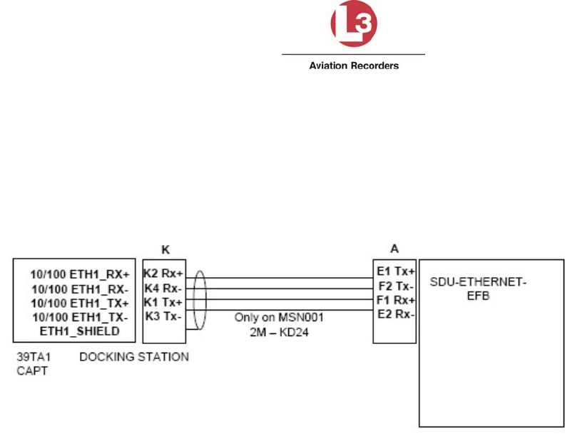
Airbus Iridium SATCOM System
165E5733-00 L-3 Aviation Recorders Proprietary
Issue, Rev. 02
21 January 2014
Page 48
Monitored
Unused Ethernet ports should be configured as “None.” A “Monitored” port is one where the system
expects an active link and it will generate a fault if the Ethernet link to the external system is not
available. For example, if the SDU is connected by Ethernet to a Class 2 EFB that is routinely turned
off and stowed for take-off and landing, the port should be configured as “Not Monitored” or the
system will generate a fault whenever the EFB is disconnected.
Figure 6-6 – Ethernet Interface
6.10 Discrete Inputs
The Airbus Iridium SATCOM System has 16 Discrete Inputs, of which 14 are software-configurable for
Open-Ground or Open-28V signaling levels, Active High or Active Low logic, and the assigned
function.
6.10.1 Landing Gear Control Interface Unit (LGCIU) Input
Discrete Input No. 1 (Din 1) is dedicated for use as a Landing Gear Control Interface Unit (LGCIU1)
input. When there is only one LGCIU input (i.e. the LGCIU2 function is not assigned to a Discrete
Input; see §6.10.2) and the ‘LGCIU1’ input transitions to the active state, the system is signaled that
the aircraft is on the ground, and the inactive state indicates that the aircraft is in the air.
LGCIU1 (Din 1) is only an Open-Ground input; it cannot be configured as an Open-28V input. A
Hardware Programming Pin (HPP) is provided to set whether the LGCIU1 input is Active High or
Active Low. If the LGCIU HPP pin (J1B-11F) is tied low, LGCIU1 is configured as an Active Low input,
i.e. Ground = On Ground. If the LGCIU HPP pin is connected to ground, LGCIU1 is configured as an
Active High input, i.e. Ground = In Air.
If one of the configurable Discrete Inputs is configured for the LGCIU2 function (see §6.10.2), the
following logic is used to determine the aircraft’s Air-Ground status:
When the ‘LGCIU1’ discrete input is in the active state (as configured by the LGCIU HPP
strapping) and the ‘LGCIU2’ discrete input is in the active state (as defined by the ICT setting
for the discrete input configured as ‘LGCIU 2’), the aircraft is considered as ‘on the ground.’

Airbus Iridium SATCOM System
165E5733-00 L-3 Aviation Recorders Proprietary
Issue, Rev. 02
21 January 2014
Page 49
When any of the LGCIU discrete inputs are in the inactive state, the aircraft is considered as
‘in the air.
6.10.2 Function Assignment
The discrete inputs are software configurable. Once a function is selected for any given input, it is no
longer available for assignment to any of the other inputs. See Figure 6-7.
The ‘Mic On’, and ‘Call Light’ functions are used in conjunction with the Extension 1 audio interface
and are discussed in §6.12.1.1 below.
Discrete Input No. 1 (Din 1) is dedicated as a LGCIU input. Only Discrete Inputs Din 2 through Din 15
are software-configurable. Discrete Input No. 16 (Din 16) is dedicated as “aircraft on ground” (LGCIU
HPP).
None
When an input is not connected to an active system (e.g. no connection, or wiring provisions
only are installed), the input should be configured as “None.”
System Reset
The System Reset Discrete Input, when configured, will reset the system only after an inactive
to active transition. The system will reset only once even if the discrete input is left active. The
System Reset function is independent of the 'In-Air' or 'On-Ground' status of the aircraft.
Landing Gear Control Interface Unit 2 (LGCIU2)
A second Landing Gear Control Interface Unit input may optionally be provided to the AFIRS
system. Refer to §6.10.1 for the logic used when a ‘LGCIU2’ input is provided.
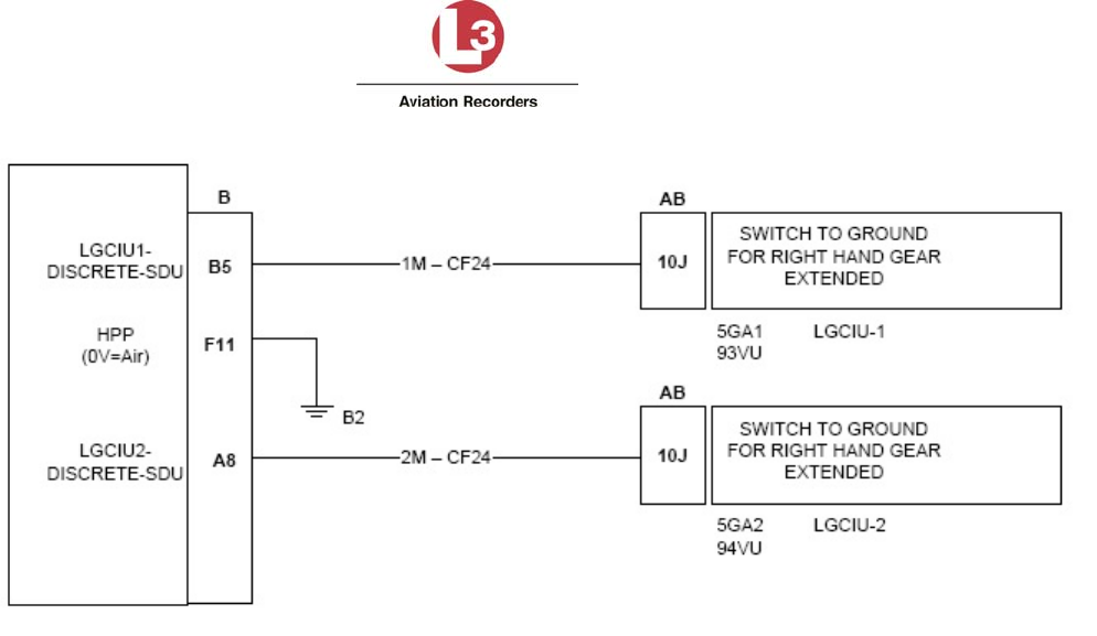
Airbus Iridium SATCOM System
165E5733-00 L-3 Aviation Recorders Proprietary
Issue, Rev. 02
21 January 2014
Page 50
Figure 6-7 – Discrete Input Interfaces
6.11 Discrete Outputs
The Airbus Iridium SATCOM System has 8 configurable Discrete Outputs, each of which is software-
configurable for Active High or Active Low logic and the assigned function. The Discrete Outputs use
‘Open-Closed’ signal levels, where the output is either high-impedance to ground (Open) or low-
impedance to ground (Closed).
Once a function (except “None”) is selected for any given output, it is no longer available for
assignment to any of the other outputs.
6.12 SATCOM
This section describes the interface and integration requirements for the Airbus Iridium SATCOM
System with an Audio Integrating System.
6.12.1 Audio Integrating System
Extension 1 is generally intended to be connected to the aircraft’s audio integrating system for flight
crew use. The interfaces required to fully support this functionality vary significantly depending on the
design of the audio integrating system. Generally, the MCDUs are used for control and display of the
SATCOM functions for Extension 1.
6.12.1.1 Audio Discrete Signals
There is one discrete input and one discrete output that can be used to support the integrated audio
interface.
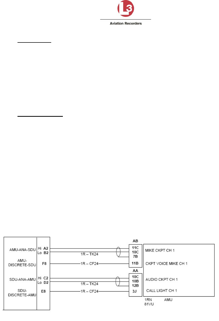
Airbus Iridium SATCOM System
165E5733-00 L-3 Aviation Recorders Proprietary
Issue, Rev. 02
21 January 2014
Page 51
Mic On Input
The ‘Mic On’ function is dedicated as a ‘Latched ACP’ mode; therefore, Voice Extension 1
(Mic/Phone input) will answer an incoming call when the ‘Mic On’ input transitions to the active
state. Once a call is in progress, the microphone audio channel will function as long as the
‘Mic On’ input is in the active state. If a call is in progress and the ‘Mic On’ input toggles to the
inactive state, the call will be terminated. For outgoing calls when the ‘Mic On’ input is
configured for ‘Latched ACP’, the function is dependent on which control source is configured
for Extension 1. When an MCDU is the Extension 1 dialing control, setting the ‘Mic On’ input to
the active state will initiate the dialing process using the phone number preselected on the
MCDU.
Call Light Output
The ‘Call Light’ output is software configurable for either steady or flashing lights. When an
incoming voice call is ringing, the ‘Call Light’ output will transition to the active state; either in a
steady state or flashing at approximately a 1 Hz rate. When the incoming call is subsequently
answered, the ‘Call Light’ output will remain active in the steady state as long as the call is in
progress. When the call in progress is terminated, the ‘Call Light’ output will go inactive.
6.12.1.2 Latched ACP Configuration
If the Audio Integrating System provides a latched Mic On output, the following interface can be used.
When an incoming call is ringing and the SATCOM switch on the Audio Control Panel is pressed, the
call will be answered and microphone audio will always be live. The SATCOM switch on the Audio
Control Panel is pressed a second time to end the call. Calls cannot be answered and terminated on
the MCDU screen in this configuration.
The following diagram also shows how the Call Light output can be interfaced to an Audio Integrating
System that provides SATCOM visual and aural call indications. In this case, a Call Light, Chime and
Chime Reset switch are not required. See Figure 6-8.
Figure 6-8 – Latched ACP Audio Interface
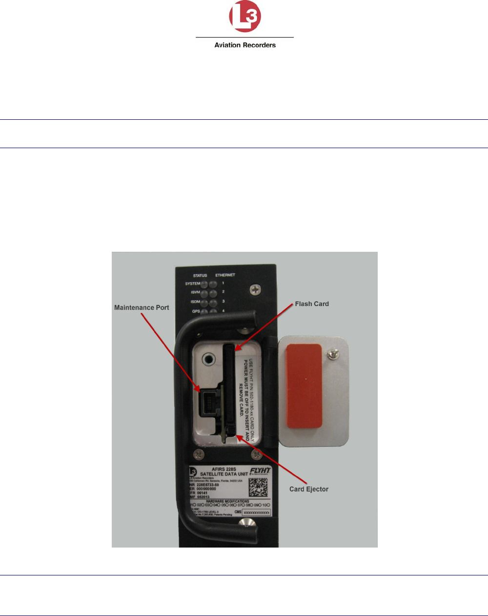
Airbus Iridium SATCOM System
165E5733-00 L-3 Aviation Recorders Proprietary
Issue, Rev. 02
21 January 2014
Page 52
7. SATCOM SYSTEM CONFIGURATION
You configure the Airbus Iridium SATCOM System Satellite Data Unit (SDU) via Ethernet using a
laptop, web browser, and the AFIRS Maintenance User Interface (MUI).
Note:
The MUI only accepts English-language characters and numbers.
IMPORTANT: This manual provides information on how to connect to the Maintenance Port and
access the Maintenance User Interface (MUI). It also provides general information on the steps
required to configure and update the Airbus Iridium SATCOM System.
The Airbus Iridium SATCOM System has an Ethernet interface for the Maintenance Port connection.
An RJ-45 Maintenance Port jack is located behind the access door on the front panel of the SDU as
shown in Figure 7-1.
Figure 7-1 – Maintenance Port Location
Note:
When performing the initial configuration of an installed system, perform and complete the Before
Power-On Tests in section 8.1 before applying power to the Airbus Iridium SATCOM System.
Airbus Iridium SATCOM System
165E5733-00 L-3 Aviation Recorders Proprietary
Issue, Rev. 02
21 January 2014
Page 53
7.1 Accessing the Maintenance User Interface (MUI)
You access the AFIRS MUI by connecting an Ethernet cable to the Maintenance Port of the SDU.
Alternatively, as described in section 6.9, Ethernet Port 1A can be used.
Also, if an Electronic Flight Bag (EFB) with a supported web browser installed is connected to one of
the rear Ethernet port connections, the EFB can be used as an AFIRS maintenance terminal and a
laptop is not required.
To access the Maintenance User Interface (MUI):
1. Connect an Ethernet cable either to the Maintenance Port via the front panel access door of
the SDU or through the rear Ethernet Port 1A connection. Note that the Airbus Iridium
SATCOM System power may be on or off.
2. Connect the other end of the Ethernet cable to a laptop that is running a web browser.
Note:
It is recommended to use Mozilla Firefox ® as the Internet browser with the SDU. The laptop
network adapter must be set to the same subnet mask as the SDU (i.e. 255.255.255.0).
3. If not already powered, apply power to the SDU.
4. Confirm that the green link light (adjacent to Maintenance Port RJ45 connector) is illuminated,
either steady or flashing (a flashing link light indicates that data is being transmitted).
5. Open a web browser on the laptop. In the Address bar, type one of the two following IP
addresses depending on the connection point:
192.168.128.1 (if connecting to the Maintenance Port at the front panel of the SDU –
see Figure 7-1.)
10.0.0.238 (if connecting to the rear Ethernet Port 1A. – see Figure 6-6).
Note:
Before opening the Web page, clear the cache of the Web browser or Ctrl+F5 and reopen the
Web page.
The Airbus Iridium SATCOM System Home page appears with the General tab information
displayed – see Figure 7-2 – Home Page – General Tab.
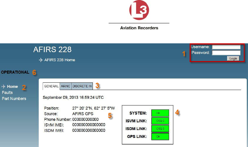
Airbus Iridium SATCOM System
165E5733-00 L-3 Aviation Recorders Proprietary
Issue, Rev. 02
21 January 2014
Page 54
Figure 7-2 – Home Page – General Tab
The default view opens to the Home page General tab (see Figure 7-2) which displays the
following information:
1 Login area
2 Menu of available links to pages accessible to various users upon login
3 Tabs: General, ARINC, and Discrete In
4 System and Link status display area
5 System information data display area
6 Mode: OPERATIONAL, MAINTENANCE, INITIALIZING, etc.
7.1.1 Home Page Tab Descriptions
To open the MUI Home Page, there is no user name and password required.
The General tab page displays:
UTC Date and Time: This is correlated to a GPS clock if ICT parameter ‘Internal GPS =
Active’. If no link is available (i.e. during startup) a default date is displayed.
Position: This is the AFIRS GPS position. If no GPS is fixed, no GPS will be displayed.
Phone Number: Displays the aircraft phone number (12 digits).
ISVM IMEI: Iridium Satellite Voice Modem International Mobile Equipment Identity (15 digits).
ISDM IMEI: Iridium Satellite Data Modem International Mobile Equipment Identity (15 digits).
Airbus Iridium SATCOM System Status Indicators:
System: Yellow (INIT) initializing; Green (OK), Yellow (FAULT), Yellow (blank) indicates that
system is in Maintenance Mode; Red indicates SDU Configuration Module (SCM) or Satellite
Data Unit (SDU) Hardware failure or other critical error.
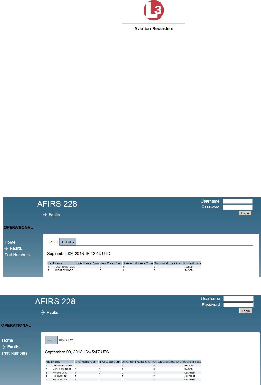
Airbus Iridium SATCOM System
165E5733-00 L-3 Aviation Recorders Proprietary
Issue, Rev. 02
21 January 2014
Page 55
ISVM LINK: Yellow (NO LINK) no Iridium link if CSQ (Channel Signal Quality) is 0-1;
Green (OK) if CSQ is 2-5
ISDM LINK: Yellow (NO LINK) no Iridium link if CSQ (Channel Signal Quality) is 0-1;
Green (OK) if CSQ is 2-5
GPS LINK: Yellow (NO FIX), Green (OK)
The ARINC tab displays the status of the 16 ARINC 429 RX channels. The status of a configured
function is either ACTIVE (green) or FAULT (red). The ARINC 717 RX configuration is currently not
used.
The DISCRETE IN tab displays the state of the 16 Discrete Inputs. The state of the configured
functional input is either ACTIVE (green) or INACTIVE (blue).
7.1.2 Faults Page
The Faults page provides access to the system fault log (see Figure 7-3), and fault history (Figure
7-4). The FAULT tab displays only currently raised faults, while the HISTORY tab displays all raised
and cleared faults since the last system reboot.
.
Figure 7-3 – Faults Page (Fault Log Tab)
Figure 7-4 – Faults Page (Fault History Tab)
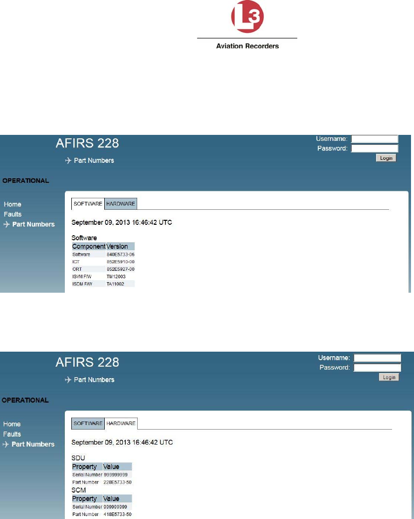
Airbus Iridium SATCOM System
165E5733-00 L-3 Aviation Recorders Proprietary
Issue, Rev. 02
21 January 2014
Page 56
7.1.3 Part Numbers Page
The Part Numbers page provides the status of the software (Figure 7-5) and hardware configuration
(Figure 7-6) of the Airbus Iridium SATCOM System.
Figure 7-5 – Part Number Page (Software Tab)
Figure 7-6 – Part Number Page (Hardware Tab)
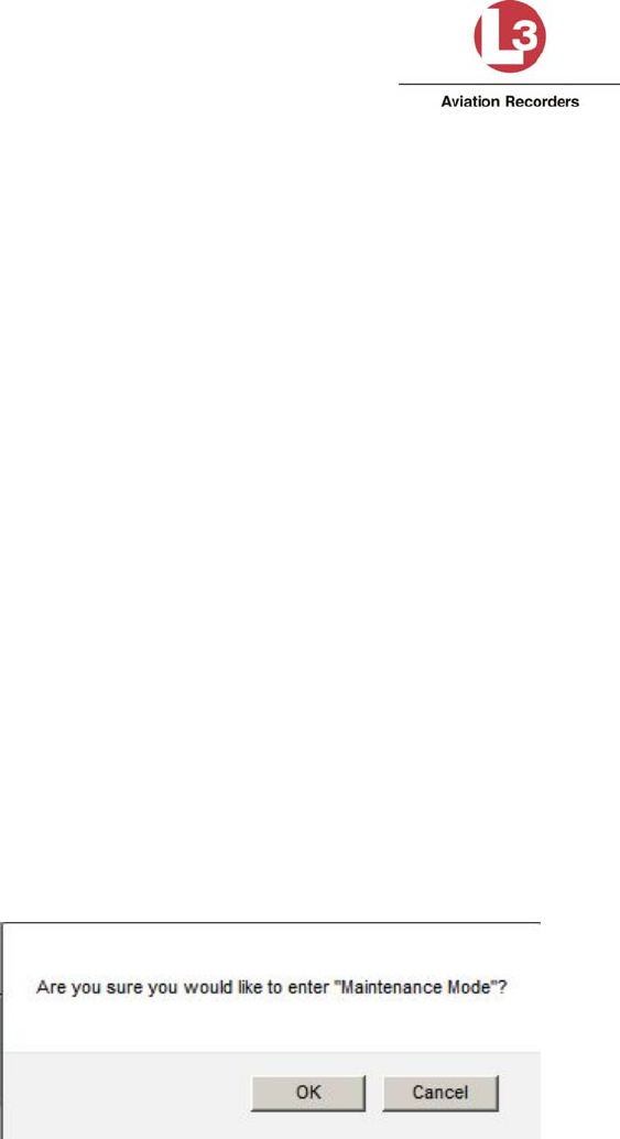
Airbus Iridium SATCOM System
165E5733-00 L-3 Aviation Recorders Proprietary
Issue, Rev. 02
21 January 2014
Page 57
7.2 Entering Maintenance Mode
In order to enter Maintenance Mode, the aircraft must be deemed ‘On-Ground’. If the aircraft is
deemed ‘In-Air’, the [Enter Maintenance Mode] button will be or will become unavailable.
If the aircraft status changes to ‘In-Air’ while in Maintenance Mode, the system will reboot
automatically and return to Operational Mode.
Entering Maintenance Mode is granted to the following users after login with their assigned user name
and password:
Maintenance User
Administrator User
Entering Maintenance Mode provides the Upgrades page to the Maintenance User and Administrator
User. In addition, the Maintenance User is allowed to modify 5 parameters in the ORT page.
The Administrator User is allowed to modify parameters in the UAT page only.
Role based MUI permissions are provided in Table 7-1 through Table 7-3 at the end of this section.
To enter Maintenance Mode:
1. Once connected to the Airbus Iridium SATCOM System MUI, on the Home page, enter your
user name and password, then click Login.
2. If the aircraft is deemed ‘On-Ground’, the [Enter Maintenance Mode] button is available at the
top right corner of the screen. Click Enter Maintenance Mode.
A message appears (see Figure 7-7) prompting for confirmation to enter Maintenance Mode.
Figure 7-7– Entering Maintenance Mode Message
3. To enter Maintenance Mode, click OK.
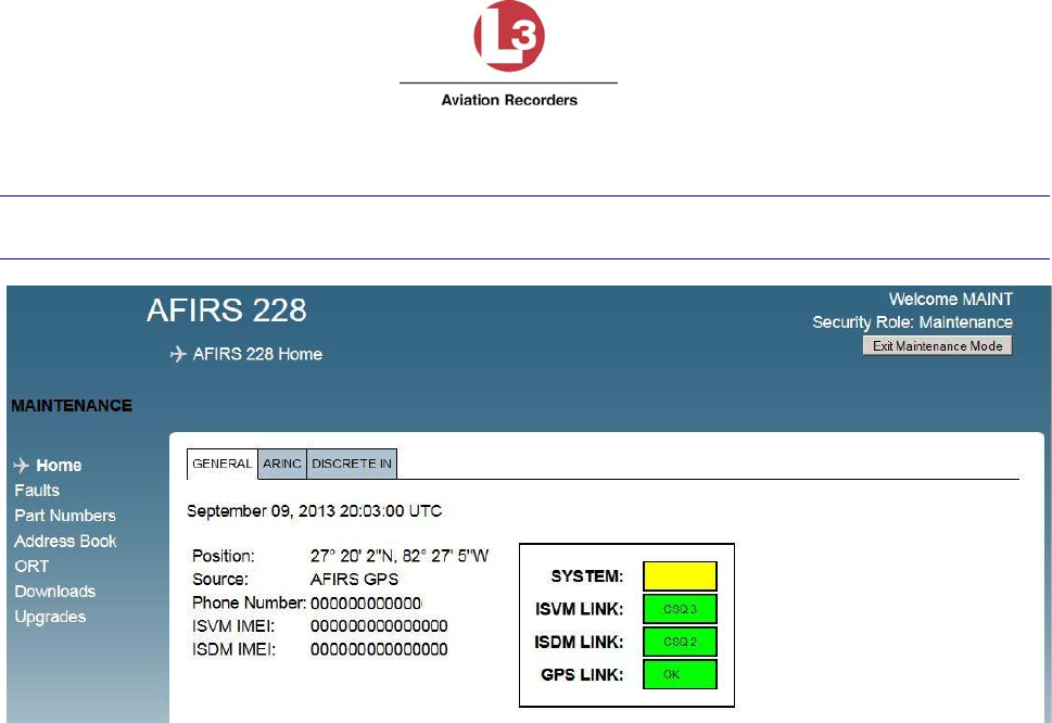
Airbus Iridium SATCOM System
165E5733-00 L-3 Aviation Recorders Proprietary
Issue, Rev. 02
21 January 2014
Page 58
The Home screen appears as shown in Figure 7-8. The SYSTEM status indicates Yellow (blank).
Note:
Entering Maintenance Mode disables all MCDU functions.
Figure 7-8 – Maintenance Mode Initial Display Screen
To exit Maintenance Mode:
Upon completion of uploading of data or software files or modifying parameters, click Exit
Maintenance Mode for the changes to take effect – see Figure 7-9.
A dialog box will appear, asking you to confirm that you want to save changes. Click OK, then the
system will restart, displaying the screen shown in Figure 7-10.
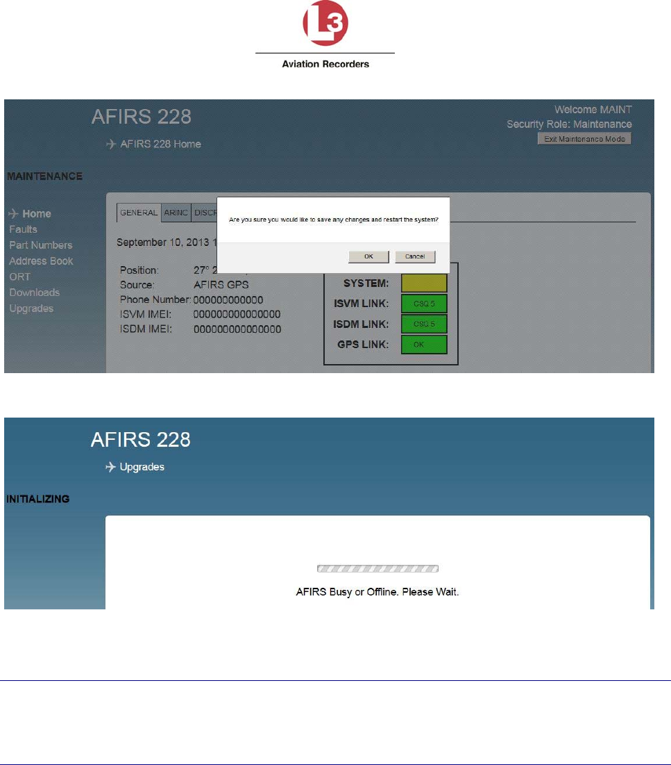
Airbus Iridium SATCOM System
165E5733-00 L-3 Aviation Recorders Proprietary
Issue, Rev. 02
21 January 2014
Page 59
Figure 7-9 – Maintenance Mode Exit Screen
Figure 7-10 – System Restart Screen
Note:
Exiting Maintenance Mode enables all MCDU functions.
If the aircraft status changes to ‘In-Air’ while in Maintenance Mode, the system will reboot
automatically and return to Operational Mode, disregarding incomplete file uploads.
The following sections describe the functionality of the additional menu items available in
Maintenance Mode.
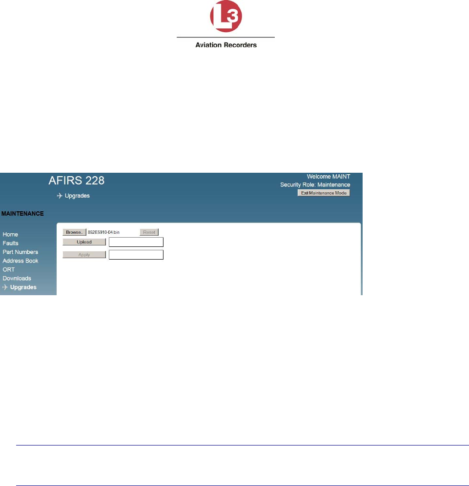
Airbus Iridium SATCOM System
165E5733-00 L-3 Aviation Recorders Proprietary
Issue, Rev. 02
21 January 2014
Page 60
7.2.1 Maintenance Mode Menu Descriptions
Entering Maintenance Mode provides the Upgrades page to the Maintenance User and Administrator
User.
1. Click Upgrades to upload software or data files. The screen shown in Figure 7-11 will be
displayed.
2. Click Browse to navigate and select the software or data file to be uploaded.
Figure 7-11 – Upgrades Screen
3. Click Upload to start the uploading process. Upon successful completion of the Upload step,
the blue progress bars turn green. The uploaded data files display a CRC code, the uploaded
software file displays the part number of the software. Non-compatible files will be rejected
and an error message displays.
4. Click Apply to start the verification process. Upon successful completion of the verification
step, the blue progress bars turn green. Non-compatible files will be rejected and an error
message displays
5. Click Reset in order to upload another file.
6. For changes to take effect, the system must be rebooted. Click Exit Maintenance Mode.
Note:
If the aircraft status changes to ‘In-Air’ before the Upload process is completed, the system
will reboot automatically and return to Operational Mode, disregarding incomplete uploads.

Airbus Iridium SATCOM System
165E5733-00 L-3 Aviation Recorders Proprietary
Issue, Rev. 02
21 January 2014
Page 61
7. Maintenance User can modify only 5 ORT parameters:
a. Click ORT (Owner Requirements Table) to configure customized settings for specific
aircraft and or operator requirements.
8. Administrator User can modify any UAT parameter:
a. Click UAT (User Access Table) to configure user access privileges.
.
9. Click Exit Maintenance Mode for changes to take effect. The system reboots and returns to
Operational Mode
Note:
If the aircraft status changes to ‘In-Air’ before the Upload process is completed, the system will
reboot automatically and return to Operational Mode, disregarding incomplete uploads.
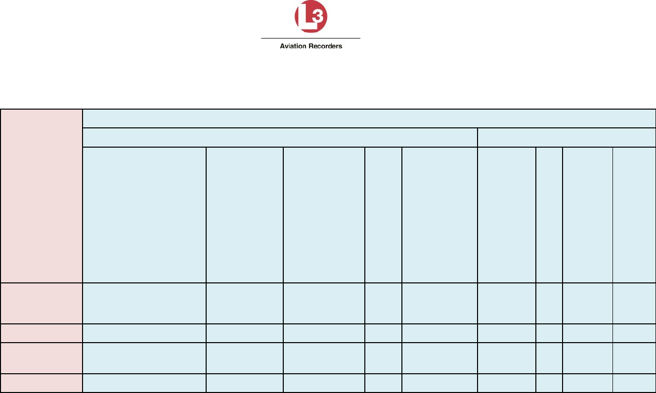
Airbus Iridium SATCOM System
165E5733-00 L-3 Aviation Recorders Proprietary
Issue, Rev. 02
21 January 2014 Page 62
Table 7-1 - Read Privileges by Role
Roles
Read Privileges
StatusandPartNumbers Configurations
Status:OperatingMode,
GPSSource,Configured
PhoneNumber,ISVMIMEI,
ISDMIMEI,StatusLEDs
(System,GPS,ISVM,ISDM)
ARINC429Rx
ChannelsStatus
(Active/
Inactive)
DiscreteInputs
Status(Active/
Inactive)
Fault
Status
PartNumbers:
ICTP/N,
ORTP/N,
ISVMF/WVer.,
ISDMF/WVer.,
S/WP/N,
SDUP/N,
SCMP/N,
SCMS/NORTICT
ADB
(Address
Book)
UAT
(User
Access
Table)
Guest
(no login
required) YesYesYesYesYesNoNoNoNo
Data Collector YesYes Yes Yes Yes No No No No
Maintenance YesYesYesYesYes
Yes
(Limited)NoYesNo
Administrator YesYes Yes Yes Yes No No Yes Yes
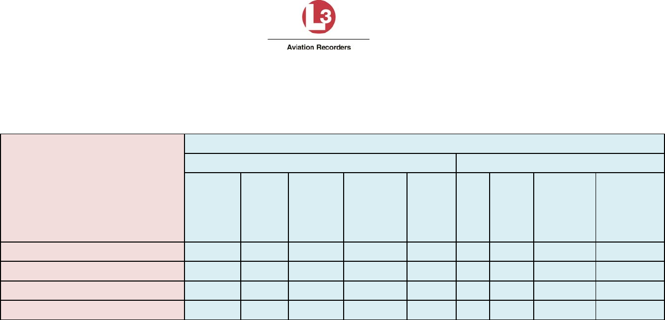
Airbus Iridium SATCOM System
165E5733-00 L-3 Aviation Recorders Proprietary
Issue, Rev. 02
21 January 2014 Page 63
Table 7-2 - Download Privileges by Role
Roles
DownloadPrivileges
Logs Configurations
Failures
In‐Air
Faults
On‐
Ground
Faults
Status(Link
Changes)DebugICTORT
ADB
(Address
Book)
UAT
(UserAccess
Table)
Guest (no login required) No No No No NoNo No No No
Data Collector Yes Yes Yes Yes YesNo No No No
Maintenance Yes Yes Yes Yes YesYes Yes Yes No
Administrator Yes Yes Yes Yes YesNo No No Yes
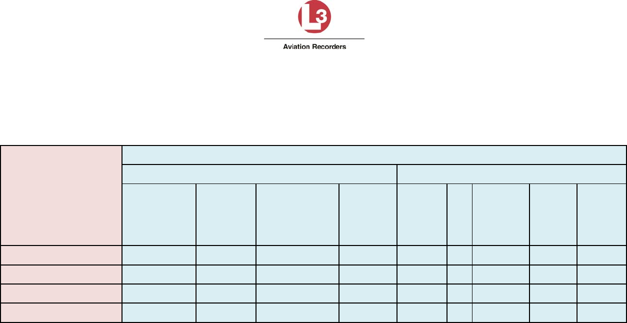
Airbus Iridium SATCOM System
165E5733-00 L-3 Aviation Recorders Proprietary
Issue, Rev. 02
21 January 2014 Page 64
Table 7-3 – Modify Privileges by Role
Roles
ModifyPrivileges
Modifications Software/DataLoading(Upload)
ORT
Parameters
ICT
ParametersAddressBook
UAT
(User
Access
Table)
S/W
Upgrades ICT
ORT
(Complete)
ADB
(Address
Book)
UAT
(User
Access
Table)
Guest (no login required) NoNo No No NoNo No No No
Data Collector NoNo No No NoNo No No No
Maintenance Yes(Limited) No No No YesYes Yes Yes Yes
Administrator NoNo No Yes YesYes Yes Yes Yes

Airbus Iridium SATCOM System
165E5733-00 L-3 Aviation Recorders Proprietary
Issue, Rev. 02
21 January 2014
Page 65
7.3 Configuring the Airbus Iridium SATCOM System
This section provides basic information on how to configure the Airbus Iridium SATCOM
System.
User access privileges are required to modify parameters as follows:
Maintenance User – 5 ORT parameters
Administrator User – UAT parameters
The above listed users are required to log in with a user name and password and enter
Maintenance Mode.
Note: The aircraft status must be ‘On-Ground’ when Entering Maintenance Mode.
The following sections are intended to provide you with information on the configuration process
and data inputs required to install and verify a system as operational: For the purposes of
installation, system configuration and verification, the following steps should be completed:
1. Address Book to upload
2. ORT parameters for Maintenance User
3. ICT file to upload
4. UAT parameters for user roles
7.3.1 Address Book
The Address Book can be uploaded as a comma-separated-values file (adb.csv) by the
Maintenance User or Administrator User after login with a user name and password, and
Entering Maintenance Mode when the aircraft status ‘On-Ground’.
The Address Book can be viewed in the MUI by the Maintenance User or Administrator User
after login in Operational Mode. Up to 300 Address Book entries can be made.
Note: Address Book entries can be viewed and, if unprotected, modified via the MCDU in
Operational Mode.
The Address Book can be downloaded as ‘adb.csv’ file in the MUI (including modifications that
have been made via the MCDU) by the Maintenance User after login in Operational Mode.
The following restrictions and limitations apply to the parameters of a compatible adb.csv file:
Phone Number – up to 18 digits
Name – up to 23 alphanumeric characters; A-Z, 0-9, +, -, /, space
Priority – 4 (Public), 3 (Non-Safety), 2 (Safety), 1 (Emergency)
Protected – 0 (No), 1 (Yes)
Directory - 4 (Public), 3 (Non-Safety), 2 (Safety), 1 (Emergency)
Speed Dial 1 - 1
Speed Dial 2 – 0 (currently not used)
Speed Dial 3 – 0 (currently not used)
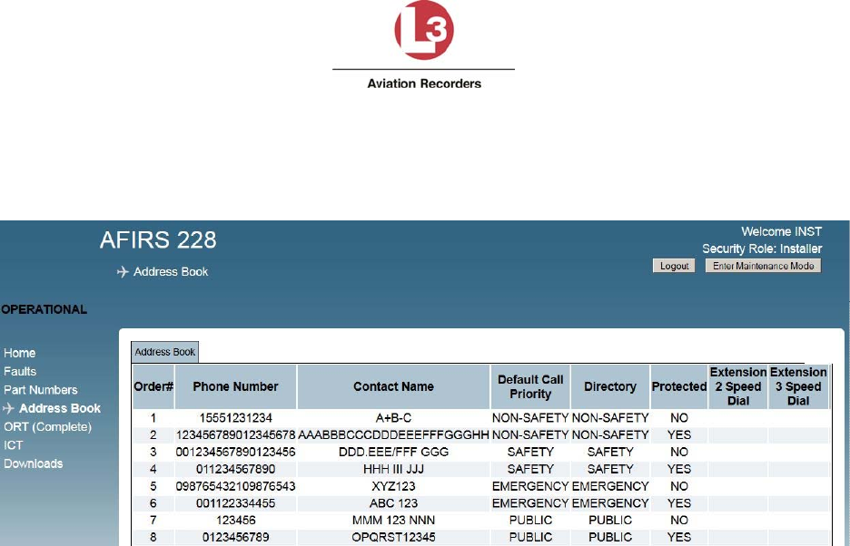
Airbus Iridium SATCOM System
165E5733-00 L-3 Aviation Recorders Proprietary
Issue, Rev. 02
21 January 2014
Page 66
To view the Address Book in the MUI:
1. In Operational Mode, log in as Maintenance User or Administrator User.
2. Click Address Book to display the Address Book entries (see Figure 7-12).
Figure 7-12 – Address Book
3. View the Address Book entries in the MUI:
Order#: Up to 300 address book entries.
Note: This parameter is not part of the adb.csv file.
Phone Number: From 6 to 18 digits
Contact Name: Up to 23 alphanumeric characters
Default Call Priority and Directory: Options displayed are Emergency, Safety,
Non-Safety, and Public.
Protected: YES indicates that the Address Book entry is ‘protected’ from being
modified. NO indicates that the Address Book entry is ‘not protected’, and can be
modified or deleted via the MCDU in Operational Mode.
Extension 2 and 3 Speed Dial: Currently not used.
7.3.2 Owner Requirements Table (ORT) Parameters
The following user access privileges are required to modify ORT parameters:
Maintenance User – 5 ORT parameters
The Owner Requirements Table (ORT) for Maintenance User (see Figure 7-13) contains the
parameters that may be customized by the individual aircraft operator. These settings may be
changed as required to meet operational requirements or preferences.
The ORT file can be uploaded and downloaded as a binary file by the Maintenance User.
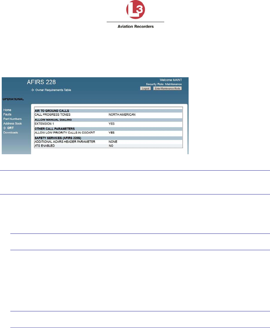
Airbus Iridium SATCOM System
165E5733-00 L-3 Aviation Recorders Proprietary
Issue, Rev. 02
21 January 2014
Page 67
The file name of an up-loadable ORT file has a part number; for example, ‘852E5927-00.bin’. It
is version-controlled and the CRC is calculated and displayed during the upload process for
verification.
The default file name of a downloaded ORT file is ‘ort.bin’.
Figure 7-13 – ORT Screen
Note:
An ORT Configuration Worksheet is provided in Appendix B to assist the operator in selecting
and documenting the correct ORT configuration settings.
To access and modify ORT parameters:
1. Log in with user name and password as Maintenance User.
2. Click Enter Maintenance Mode.
Note:
The aircraft status must be ‘On-Ground’ to be able to Enter Maintenance Mode.
3. Click the ORT link on the left-hand side of the screen to open the ORT page.
4. AIR TO GROUND CALLS - CALL PROGRESS TONES: The call progress tones can be
configured to either North American or European. The default is NORTH AMERICAN.
5. ALLOW MANUAL DIALING - EXTENSION 1: If set to YES, manually dialed phone
calls can be placed from the cockpit, in addition to using the directory. If set to NO,
phone calls from the cockpit can be placed only by using the directory.
Note:
If set to NO, the MANUAL DIAL prompt will not be available on the MCDU.
IMPORTANT! To obtain operational approval for safety-services voice in accordance with
FAA AC20-150A, Extension 1 must be configured YES to allow manual dialing for the flight
crew.

Airbus Iridium SATCOM System
165E5733-00 L-3 Aviation Recorders Proprietary
Issue, Rev. 02
21 January 2014
Page 68
6. OTHER CALL PARAMETERS – ALLOW LOW PRIORITY CALLS IN COCKPIT: Low-
priority calls are considered PUBLIC or Priority 4. If set to YES, low-priority calls can be
received in the cockpit, and low-priority calls can be placed from the cockpit. If set to
NO, low-priority incoming calls will not ring in the cockpit, and no low-priority calls can be
placed from the cockpit.
Note:
If set to NO, the PUBLIC directory prompt will not be available on the MCDU.
7. SAFETY SERVICES (Airbus Iridium SATCOM System) – ADDITIONAL ACARS
HEADER PARAMETER: The default configuration of NONE corresponds to SITA;
alternatively, select ARINC.
8. ATS ENABLED: If set to YES, the Iridium SIM card installed in the SCM must be ATS-
enabled. If set to NO, the Iridium SIM card installed in the SCM is not ATS-enabled.
7.3.3 Installation Configuration Table (ICT)
The Installation Configuration Table (ICT) parameters may not be viewed or modified.
The ICT file can be uploaded and downloaded as a binary file by the Maintenance User.
The file name of an uploadable ICT file has a part number; for example, ‘852E5910-00.bin’. It is
version-controlled and the CRC is calculated and displayed during the upload process for
verification.
The default file name of a downloaded ICT file is ‘ict.bin’.
7.3.4 User Access Table (UAT) Parameters
The following user access privileges are required to modify UAT parameters:
Administrator User
The User Access Table (UAT), shown in Figure 7-14, is used by the Administrator User to set
up user access privileges for up to 20 users. These settings may be changed as required to
meet operational requirements.
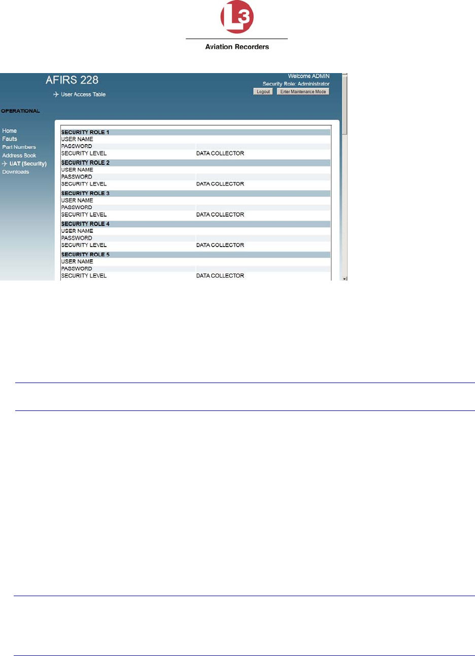
Airbus Iridium SATCOM System
165E5733-00 L-3 Aviation Recorders Proprietary
Issue, Rev. 02
21 January 2014
Page 69
Figure 7-14 – UAT Page
To access and modify UAT parameters:
1. Log in with user name and password as Administrator User
2. Click Enter Maintenance Mode.
Note:
The aircraft status must be “On-Ground” to be able to Enter Maintenance Mode.
3. Click the UAT (Security) link on the left-hand side of the screen to open the UAT page.
4. USER NAME: From 4 to 20 upper-case alphanumeric characters
5. PASSWORD: From 4 to 20 upper-case alphanumeric characters
6. SECURITY LEVEL: Select either DATA COLLECTOR (default) or MAINTENANCE or
ADMINISTRATOR.
Up to 20 Users can be configured.
To exit Maintenance Mode:
Upon completion of modifying parameters, click Exit Maintenance Mode for the system to
reboot and the changes to take effect.
Note:
Exiting Maintenance Mode enables all MCDU functions.
If the aircraft status changes to ‘In-Air’ while in Maintenance Mode, the system will reboot
automatically and return to Operational Mode.

Airbus Iridium SATCOM System
165E5733-00 L-3 Aviation Recorders Proprietary
Issue, Rev. 02
21 January 2014
Page 70
7.4 Upgrading Airbus Iridium SATCOM System Software
The Airbus Iridium SATCOM System software is field-upgradeable using the Upgrade function
of the MUI in Maintenance Mode.
One of the following user privileges is required to login and enter Maintenance Mode to upload
software and data files:
Maintenance User
Administrator User
Note:
The aircraft status must be ‘On-Ground’ to enter Maintenance Mode.
7.4.1 Upgrade Materials
Make sure you have the following materials available before beginning the upgrade procedure.
A notebook computer with an Ethernet port, running the Microsoft Windows operating
system and a web browser such as Internet Explorer (see Section 7.1 Accessing the
Maintenance Port).
A standard, straight-through Ethernet patch cable.
The software release folder that contains the upgrade file (upgrade.tgz).
The software release notes to identify any changes to functionality or special upload
instructions.
7.4.2 Upgrade Procedure
Before beginning the upload procedure, make sure you have saved the applicable software
release folder that includes the upgrade.tgz file to an accessible location on your laptop. Make
sure you review the software release notes for any special instructions that may apply.
To upgrade the Airbus Iridium SATCOM System Software:
1. From the left-hand menu, click Upgrades.
The Upgrades screen displays.
2. Click Browse to locate the software file to upload (upgrade.tgz).
3. Once you have selected the software file you want to upload, click Upload to start the
upload process.
Blue progress bars indicate the file uploading status. When the upload is complete and
successful, the progress bars turn green, and the new Software Part Numbers of the
new software image will be displayed (see Figure 7-15).
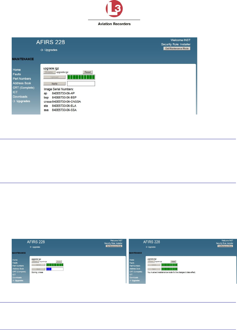
Airbus Iridium SATCOM System
165E5733-00 L-3 Aviation Recorders Proprietary
Issue, Rev. 02
21 January 2014
Page 71
Figure 7-15 – Software Upgrade Progress
Note:
Incompatible files will be rejected. The progress bars turn red, and an error message
displays next to the progress bars. Click Reset to restart the upgrade process.
If you uploaded an incorrect file, but have not yet clicked Apply, click Reset to restart the
upgrade process.
4. Click Apply to verify and load the software into non-volatile memory.
Blue progress bars indicate the status of the software file being installed on the SDU.
When the software verification is completed successfully, the progress bars turn green,
and the message displays that the system must be restarted for the changes to take
effect (see Figure 7-16).
Figure 7-16 – Software Loading Progress Screens
Note:
If the aircraft status changes to ‘In-Air’ at any time during the Upgrade process, the system
will reboot automatically and return to Operational Mode, disregarding any incomplete
upgrades.
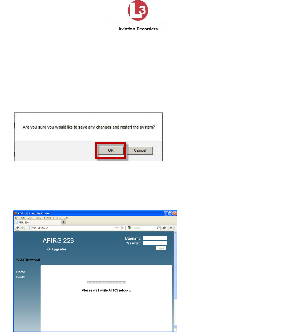
Airbus Iridium SATCOM System
165E5733-00 L-3 Aviation Recorders Proprietary
Issue, Rev. 02
21 January 2014
Page 72
To activate the newly installed software, you must Exit Maintenance Mode and restart the
SDU.
5. To exit Maintenance mode, click Exit Maintenance Mode at the top-right corner of the
MUI screen,
A confirmation message displays prompting to confirm that you want to exit Maintenance
Mode (see Figure 7-17).
Figure 7-17 – Exit Maintenance Mode Message
6. Click OK.
The SDU automatically restarts and applies the newly installed software. A message
displays indicating that the AFIRS system reboots (see Figure 7-18).
Figure 7-18 – Exit Maintenance Mode Progress Bar
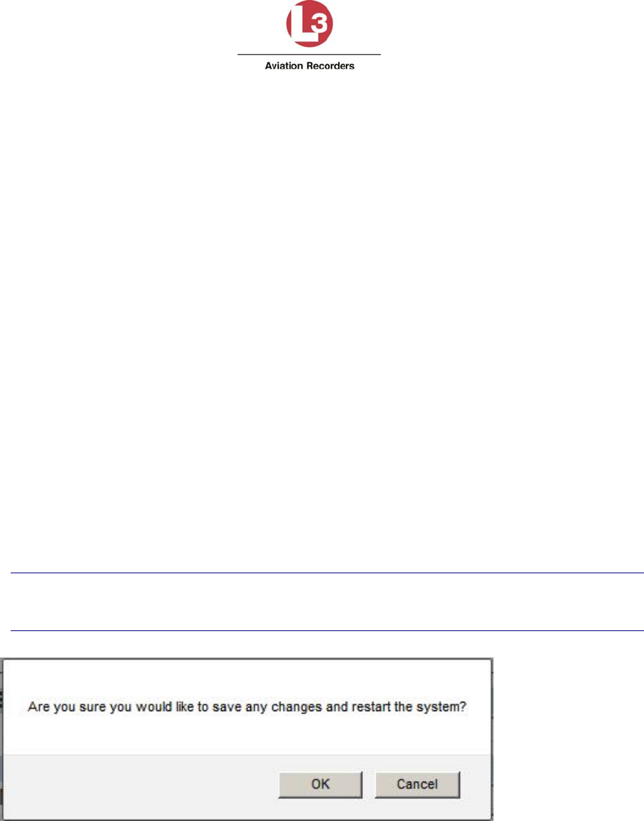
Airbus Iridium SATCOM System
165E5733-00 L-3 Aviation Recorders Proprietary
Issue, Rev. 02
21 January 2014
Page 73
7. When the restart is complete, verify that the SDU is in Operational Mode and
functioning as expected. To verify that the correct software version and
configurations have been loaded, check the following:
a. From the Home page, click on the General, ARINC, and Discrete In tabs to
review the system and link status, and the status of the ARINC 429 Rx and
Discrete In connections.
b. Click on the Faults page to view if any faults are currently raised.
c. Click on the Part Numbers page to verify that the software part number
displayed matches the software version and part number as noted in the release
notes or upgrade instructions
d. Enter User Name and Password (Maintenance User) and click Login.
e. Maintenance User - Click ORT and review the ORT configurations to confirm that
they are correct.
f. Click Logout after your review is complete and satisfactory.
7.5 Exiting Maintenance Mode
To save changes and uploaded configuration data, you need to exit maintenance mode for
the changes to take effect
1. In the top-right hand corner of the screen, click Exit Maintenance Mode.
2. A Message displays prompting for confirmation to exit Maintenance Mode
(see Figure 7-19).
Note:
If you click Cancel, your changes are still active but not saved.
Figure 7-19 – Exiting Prompt Message
3. Click OK to exit Maintenance Mode, save your changes and reboot the system.
4. The following message displays (see Figure 7-20):
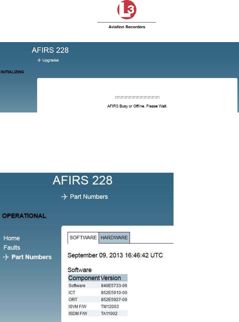
Airbus Iridium SATCOM System
165E5733-00 L-3 Aviation Recorders Proprietary
Issue, Rev. 02
21 January 2014
Page 74
Figure 7-20 – Restart Screen
5. Once the system reboots to Operational Mode, verify your changes and confirm that
the correct software and data files have been installed.
6. Click the Part Numbers page and review the Software tab for the correct Part
Numbers
7. The Part Numbers screen displays as shown in Figure 7-21.
Figure 7-21 – Software Part Numbers Screen
Airbus Iridium SATCOM System
165E5733-00 L-3 Aviation Recorders Proprietary
Issue, Rev. 02
21 January 2014
Page 75
8. MAINTENANCE AND CHECKOUT
This section provides instructions on post-installation checkout procedures and information on
Instructions for Continued Airworthiness.
8.1 Post-Installation Checkout
8.1.1 Before Power-On Tests
1. Before installing the SDU in the mounting tray, confirm that all aircraft interface wiring is
correct as per the aircraft wiring integration design.
2. Confirm that a valid SIM card is installed in the SDU Configuration Module (SCM).
3. Set the system circuit breaker for the Main power source and confirm that 28 VDC power
is available between pins J1C-2 and J1C-3. Pull the circuit breaker and ensure that Main
power is removed.
4. Place the SDU in the mounting tray and secure the front hold-down.
5. Open the front panel door and confirm that a flash card is installed in the SDU.
Note:
If no flash card is present, a FLASH CARD FAULT is generated in the MUI, and an SDU
FAIL will display on the MCDU SATCOM BITE STATUS page. Only FLYHT P/N 502-
1180-x flash cards should be used in the Airbus Iridium SATCOM System.
6. If installed, the cockpit FAULT indication should be illuminated when power is not
applied to the system.
7. Set the system circuit breaker for the Main power source. The SYSTEM LED indicator
on the front panel of the SDU will be amber indicating that the system is initializing.
Note:
The first time an SDU is installed in an aircraft, the SYSTEM LED indicator will typically
remain amber even after it has initialized. The MUI will display an SCM Configuration
Fault indicating that the proper configuration settings have not yet been made.
8. Connect an Ethernet cable to the Maintenance Port in the front panel and follow
procedures to open the Maintenance User Interface (MUI) as described in Section 7.
9. Log in to the MUI as Maintenance User and Enter Maintenance Mode to install ICT and
ORT files in accordance with the procedures contained in Section 7. Exit Maintenance
Mode to reboot the system. Keep the laptop connected to the Maintenance Port after
finishing the configuration procedure.
10. Once the system resets, the SYSTEM LED indicator on the front panel of the SDU will
turn green once the system is operational.
11. The cockpit FAULT annunciator should remain illuminated whenever the SYSTEM
STATUS indicator is amber, and extinguish when the SYSTEM LED indicator turns
green.

Airbus Iridium SATCOM System
165E5733-00 L-3 Aviation Recorders Proprietary
Issue, Rev. 02
21 January 2014
Page 76
8.1.2 Aircraft Systems Interface Tests
Note:
The tests listed in this section are generic in nature and are not intended to be used as a
test plan for any specific aircraft installation. They should only be used by the aircraft
systems integrator as a guide in developing the correct and complete aircraft-specific
integration tests. The aircraft systems integrator’s test plan should ensure that the
aircraft and its systems are in a safe condition for each test to be performed.
8.1.2.1 Main Power Test
1. Confirm that 28 VDC power is available at the Main power input, and that the Airbus
Iridium SATCOM System is initialized and operating.
2. Using the MUI Home page General tab, confirm that the System status and Datalinks
are green.
8.1.2.2 ARINC 429 Databus Interface Tests
1. On the MUI, click on the ARINC tab on the Home page.
2. Confirm the aircraft systems connected to the databus ports being tested are operational
and transmitting on the databus.
3. Confirm that the ARINC 429 Rx (1-16) channels used are shown as ACTIVE.
8.1.2.3 MCDU Tests
Confirm SATCOM functionality on each MCDU as follows:
1. On the MCDU MENU page, the <SAT prompt should be available at one of the Line
Select Keys (LSKs). Press the LSK to display the SATCOM MAIN MENU page.
2. On the SATCOM MAIN MENU, press the LSK for the SATCOM STATUS page. The
SATCOM STATUS page should be displayed with log-on state as well as voice and
datalink status information.
3. On the SATCOM STATUS page, press the LSK of the CONFIG prompt. The SATCOM
CONFIG page 1 of 7 should be displayed. Press Arrow Down or Arrow Up to view
current configurations on pages 1 through 7.
4. On the SATCOM STATUS page, press the LSK of the BITE prompt to display the
SATCOM BITE STATUS page to display the status of the SDU, SIM CARDS, and SCM.
5. On the SATCOM BITE STATUS page, press the LSK of the SYS BUS prompt. The
SATCOM SYS BUS page should display with status information of the CFDS, MCDU#1,
MCDU#2, MCDU#3, ATSU#1, ATSU#2, and EFB.
6. Press the <RETURN LSK several times to return to the SATCOM MAIN MENU page.

Airbus Iridium SATCOM System
165E5733-00 L-3 Aviation Recorders Proprietary
Issue, Rev. 02
21 January 2014
Page 77
8.1.2.4 Ethernet Port Tests
Confirm Ethernet connectivity to each Ethernet device as follows:
Confirm that the SDU front panel ETHERNET LEDs for the connected ports are green. Flashing
green indicates data is being transferred.
Perform any tests specific to the connected system to confirm that it is communicating with the
SDU over the Ethernet port.
8.1.2.5 Discrete Input Tests
For each discrete input connected (1-16), confirm the correct aircraft system interface as
follows:
1. Using the Maintenance User Interface (MUI), click on the Discrete In tab on the Home
page.
2. Select the discrete input to its inactive state. Confirm proper operation of the interfaced
aircraft system.
3. Select the discrete input to its active state. Confirm proper operation of the interfaced
aircraft system.
8.1.2.6 Discrete Output Tests
For each discrete output configured and connected (1-8), confirm the correct state is detected
as follows:
1. Manipulate the system providing the discrete output as required to indicate the output
active state
8.1.3 Operational System Tests
Note:
The tests in this section require the aircraft to be powered and outside the hangar in a location
that has a clear view of the Iridium and GPS satellites. Aircraft systems that interface with the
Airbus Iridium SATCOM System must be installed and operational.
These tests also require the AFIRS system activated on the Iridium network by FLYHT, and a
valid SIM card installed in the SCM. Ensure that the ORT configuration ATS Enabled (Yes/No)
matches the SIM card type installed.
8.1.3.1 Date, Time, and Position Tests
1. Open the MUI to display the AFIRS Home page.
2. Confirm that the correct date, time, and position (UTC) information is displayed.
3. If the Internal GPS is configured as Active, the MUI display is showing AFIRS GPS and
the GPS Link is displayed green.
8.1.3.2 Datalink Tests
1. Confirm on the MUI that the ISVM and ISDM Links are green, and the MCDU SATCOM
STATUS page displays LOGGED-ON.

Airbus Iridium SATCOM System
165E5733-00 L-3 Aviation Recorders Proprietary
Issue, Rev. 02
21 January 2014
Page 78
8.1.3.3 SATCOM Voice Tests
1. Confirm that the MCDU SATCOM MAIN MENU page displays Ready to Connect.
2. Place an air-to-ground call by using the MCDU. Confirm proper MCDU indications for a
call in progress.
3. Terminate the call from the cockpit. Confirm proper cockpit indications and return to
Ready to Connect state.
4. Place a ground-to-air call. Confirm proper cockpit indications for an incoming call.
Answer the call and confirm proper cockpit indications for a call in progress.
5. Place a ground-to-air call and reject the incoming call. Confirm proper cockpit
indications.
6. Place a ground-to-air call. Allow call to go unanswered. Confirm proper ring sequencing,
eventual call termination, and proper cockpit indications.
7. If SIM card installed is ATS-enabled, place a ground-to-air call. While the call is in
progress, place a higher priority ground-to-air call. Confirm that the existing call is
terminated and preempted by a call of higher priority.
8. Terminate call at from the ground. Confirm proper cockpit indications.
8.1.4 EMI Tests
Each Airbus Iridium SATCOM System aircraft installation should be tested for electromagnetic
interference in accordance with procedures developed by the aircraft systems integrator. The
tests should be developed to ensure that there is no objectionable interference between the
Airbus Iridium SATCOM System and other aircraft systems. This can include ground tests with
engine running and flight tests as required.
8.2 Instructions for Continued Airworthiness
The aircraft systems integrator is responsible to provide Instructions for Continued Airworthiness
(ICA) for the Airbus Iridium SATCOM System specific to the aircraft installation. The general
content in this Installation Manual may be referenced by the aircraft systems integrator when
developing the ICA.

Airbus Iridium SATCOM System
165E5733-00 L-3 Aviation Recorders Proprietary
Issue, Rev. 02
21 January 2014
Page 79
Appendix A – Wiring Diagram (follows on next 3 pages)
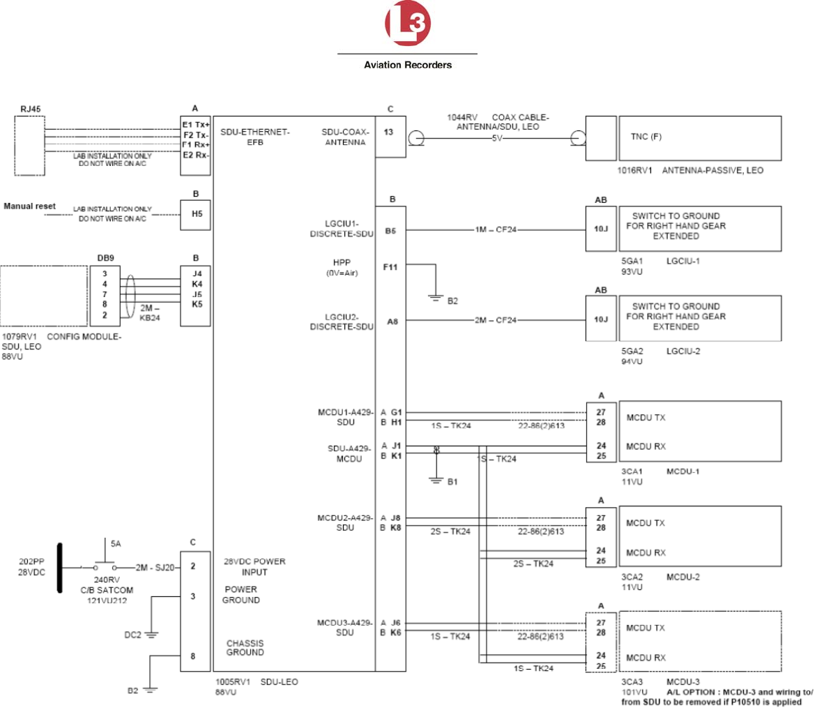
Airbus Iridium SATCOM System
165E5733-00 L-3 Aviation Recorders Proprietary
Issue, Rev. 02
21 January 2014 Page 80
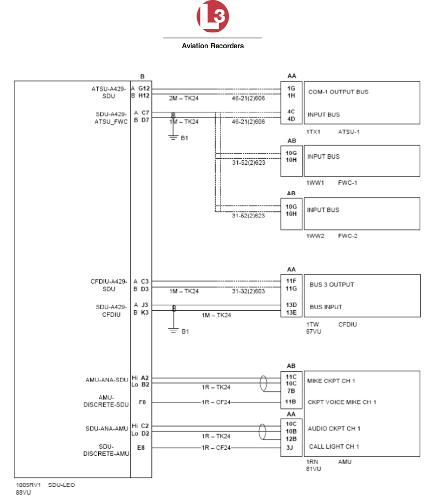
Airbus Iridium SATCOM System
165E5733-00 L-3 Aviation Recorders Proprietary
Issue, Rev. 02
21 January 2014 Page 81
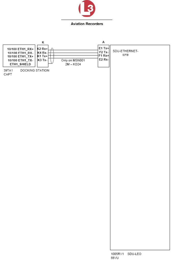
Airbus Iridium SATCOM System
165E5733-00 L-3 Aviation Recorders Proprietary
Issue, Rev. 02
21 January 2014 Page 82
Airbus Iridium SATCOM System
165E5733-00 L-3 Aviation Recorders Proprietary
Issue, Rev. 02
21 January 2014
Page 83
Appendix B – ORT Worksheet
ORTGroupORTParameterNameValue
AirtoGround
Calls
CallProgressTones NORTHAMERICAN
EUROPEAN
AllowManual
Dialing
Extension1 YES
NO
OtherCall
Parameters
AllowLowPriorityCallsinCockpit YES
NO
SafetyServices
(Airbus Iridium
SATCOM
System)
AdditionalACARSHeaderParameter NONE
ARINC
ATSEnabled YES
NO

Airbus Iridium SATCOM System
165E5733-00 L-3 Aviation Recorders Proprietary
Issue, Rev. 02
21 January 2014
Page 84
THIS PAGE INTENTIONALLY LEFT BLANK

Airbus Iridium SATCOM System
165E5733-00 L-3 Aviation Recorders Proprietary
Issue, Rev. 02
21 January 2014
Page 85
Appendix C – Environmental Qualification Forms
The following forms are provided for the Airbus Iridium SATCOM System SDU and Airbus
Iridium SATCOM System SCM, and Airbus Iridium Antenna System respectively.
Airbus Iridium SATCOM System
165E5733-00 L-3 Aviation Recorders Proprietary
Issue, Rev. 02
21 January 2014
Page 86
RTCA DO-160G Environmental Qualification Form
Model: AFIRS 228S
Product: Satellite Data Unit and Satellite Control Module
Part Number: 228E5733-00
418E5733-00
Manufacturer: L-3 Communications, Aviation Recorders
100 Cattlemen Road, Sarasota FL, 34232
P.O. Box 3041, Zip Code 34230-3041
TSO Number:
Manufacturer's Specification and/or Other Applicable
Specifications: Aviation Recorders QTP #905-E5750-34
Airbus Purchaser Technical Specification,
X2328SP1010161
Airbus ABD0100.1.2
Airbus ABD0100.1.6
Airbus ABD0100.1.8
RTCA DO-160G
Conditions TEST
STANDARD Description of Conducted Tests
Temperature & Altitude
Low Temperature
Ground Survival
Start-up after ground soak
Operating
High Temperature
Ground Survival
Start-up after ground soak
Operating
DO-160G,IAW
ABD100.1.2 G
4.5.1
4.5.1
4.5.2
4.5.3
4.5.3
4.5.4
Equipment tested to Category A2
-55C
-40C
-15C
+85C
+70C
+70C

Airbus Iridium SATCOM System
165E5733-00 L-3 Aviation Recorders Proprietary
Issue, Rev. 02
21 January 2014
Page 87
Conditions TEST
STANDARD Description of Conducted Tests
Altitude 4.6.1 +15,000 feet
Decompression 4.6.2 +8,000 feet
+50,000 feet
Overpressure 4.6.3 Equipment tested at 183 kPa and 199 kPa
(Absolute Pressure)
Temperature Variation DO-160G,
Section 5
IAW
ABD100.1.2 G
Equipment tested to Category B.
Humidity DO-160G,
Section 6.0
IAW
ABD100.1.2 G
Equipment tested to Category A (Standard).
Operational Shocks
DO-160G
Section 7.0,
IAW
ABD100.1.2 G
Equipment tested to Category D.
6g, 20 milliseconds (low freq.)
Vibration
DO-160G
Section 8
Section 8.5.2
IAW
ABD1001.2.G
DO-160G
Section 8.7.2
X20RP09234
18
Equipment tested to Section 1.6.1, Curve 1
Equipment tested to Cat H (Curve R)
Equipment tested to specification
(Windmilling)
Waterproofness DO-160G
Section 10.3.1
IAW
ABD100.1.2 G
Section 1.8
Equipment tested to Category Y.
Condensing water proof test.
Airbus Iridium SATCOM System
165E5733-00 L-3 Aviation Recorders Proprietary
Issue, Rev. 02
21 January 2014
Page 88
Conditions TEST
STANDARD Description of Conducted Tests
Fluids Susceptibility DO-160G
Section 11.4.1
IAW
ABD100.1.6 D
Sections 4.7
and 4.8
Equipment tested to Category F, for:
Cleaning Agents
Disinfectants
Extinguishing Agents
Insecticides
Heat Transfer Fluids
Hydraulic Fluid
Dust DO-160G
Section 12.4,
IAW
ABD100.1.2 G
Section 1.10
Equipment qualified to Category D
Fungus Resistance DO-160G
Section 13.0
and IAW
ABD100.1.2 G
Section 1.11
Equipment qualified to Category F
Magnetic Effect DO-160G
Section 15.0
IAW
ABD100.1.2 G
Section 3.4.1
Equipment tested to Category A.
Power Input
DO-160G
Section 16.0,
IAW
ABD100.1.8
Issue E
Equipment tested in accordance with
ABD0100.1.8 for 28VDC equipment.
Note: Low voltage +20V-DC deviating from
requirement of 18.5V-DC
Voltage Spike DO-160G
Section 17.0
IAW
ABD100.1.8
Issue E
Category A
Equipment tested in accordance with
ABD0100.1.8.1, LDC 104.
Audio Frequency Susceptibility DO-160G
Section 18.0
IAW
ABD100.1.8
Issue E
Equipment tested to Category R for DC

Airbus Iridium SATCOM System
165E5733-00 L-3 Aviation Recorders Proprietary
Issue, Rev. 02
21 January 2014
Page 89
Conditions TEST
STANDARD Description of Conducted Tests
Induced Signal Susceptibility
Magnetic Fields
Magnetic Fields
Electric Fields
Spikes
DO-160G
Section 19.0
IAW
ABD100.1.2 G
Section 3.4.4
19.3.1
19.3.3
19.3.4
19.3.5
Equipment tested to Category ZW.
Equipment
Cables
Cables
Cables
Electrostatic Discharge
IAW
ABD100.1.2 G
Section 3.5
Equipment tested Category B
Flammability/Smoke/Toxicity DO-160G
ABD0031
Analysis for Flammability
Analysis for Smoke & Toxicity
Constant Acceleration ABD100.1.2 G
Section 1.18,
Equipment tested to Category B
and Test Procedure to ISO2669
Bench Handling
IAW
ABD100.1.2 G
Section 1.5.3
and
MIL-STD 810
Method 516.5
Equipment tested to Procedure VI.
Airbus Iridium SATCOM System
165E5733-00 L-3 Aviation Recorders Proprietary
Issue, Rev. 02
21 January 2014
Page 90
L-3 Aviation Recorders
100 Cattlemen Road
Sarasota, FL 34232
Telephone: 1-941-371-0811
Fax: 1-941-377-5591
E-mail support: DLAR-aviationproducts@L-3com.com
Website: http://www.L-3ar.com

COMPONENT MAINTENANCE MANUAL
AIRBUS IRIDIUM SATCOM SYSTEM
AIRBUS IRIDIUM SATCOM SYSTEM
IRIDIUM SATCOM SYSTEM
PART NUMBERS
SDU - 228E5733-00
SCM - 418E5733-00
COMPONENT MAINTENANCE MANUAL
WITH
ILLUSTRATED PARTS LIST
P/N: 165E5733-10
IN ACCORDANCE WITH
TSO C-159a
VENDOR CODE: 06141
23-28-01
Revision 1
Jan. 21/14

AVIATION RECORDERS
COMPONENT MAINTENANCE MANUAL
AIRBUS IRIDIUM SATCOM SYSTEM
EXPORT CONTROL STATEMENT IRIDIUM SATCOM
TECHNOLOGY / DATA:
“This Iridium SATCOM System Technical Data is being exported from
the United States in accordance with the Export Administration
Regulations (ECCN #7A994), No License Required (NLR). Diversion
contrary to U.S. law is prohibited. In accordance with U.S. Law (Title
15CFR Part 746 and Supplement No. 1 to Part 774; and Title 31CFR)
resale/re-export or transfer to certain designated countries is
prohibited without the prior written consent of the U.S. Department of
Commerce.”
HTSUS/Schedule B: 85439.09.000
This manual contains date sensitive information. To verify the latest
revision level of this manual check the Publications Index located on the
L-3Com Publications down-load site at http://www.L3ar.net.
©Copyright 2013 by L-3 Communications.
All rights reserved. No part of this manual may be reproduced or utilized
in any form or by any means, electronic or mechanical, including
photocopying, recording, or by information storage and retrieval system,
without permission in writing.
Inquiries should be addressed to:
L-3 Communications,
Aviation Recorders Publications
Vendor Code: 06141
P. O. Box 3041 Sarasota, Florida 34230
Phone: (941) 371-0811;
FAX: (941) 377-5591
Title
Page ii
Jan. 21/14
23-28-01

AVIATION RECORDERS
COMPONENT MAINTENANCE MANUAL
AIRBUS IRIDIUM SATCOM SYSTEM
GENERAL
This product and related documentation must be reviewed for familiarization with safety markings
and instructions before operation.
This instrument was constructed in an ESD (electro–static discharge) protected environment. This is be
cause most of the semiconductor devices used in this instrument are susceptible to damage by static dis
charge.
Depending on the magnitude of the charge, device substrates can be punctured or destroyed by contact or
mere proximity of a static charge. The results can cause degradation of device performance, early failure,
or immediate destruction.
These charges are generated in numerous ways such as simple contact, separation of materials, and nor
mal motions of persons working with static sensitive devices.
When handling or servicing equipment containing static sensitive devices, adequate precautions must be
taken to prevent device damage or destruction.
Only those who are thoroughly familiar with industry accepted techniques for handling static sensitive de
vices should attempt to service circuitry with these devices.
In all instances, measures must be taken to prevent static charge build–up on work surfaces and persons
handling the devices.
BEFORE APPLYING POWER
Verify that the product is set to match the available line voltage and the correct fuse is installed.
Servicing instructions are for use by service–trained personnel only. To avoid dangerous electric shock, do
not perform any servicing unless qualified to do so.
Adjustments described in the manual are performed with power supplied to the instrument while protective
covers are removed. Energy available at many points may, if contacted, result in personal injury.
Title
Page iii
Jan. 21/14
23-28-01
AVIATION RECORDERS
COMPONENT MAINTENANCE MANUAL
AIRBUS IRIDIUM SATCOM SYSTEM
THIS PAGE IS INTENTIONALLY LEFT BLANK
Title
Page iv
Jan. 21/14
23-28-01

AVIATION RECORDERS
COMPONENT MAINTENANCE MANUAL
AIRBUS IRIDIUM SATCOM SYSTEM
SERVICE BULLETIN LIST
SERVICE
BULLETIN
DATE
EFFECTIVITY
DESCRIPTION
Service Bulletin
Page v
Jan. 21/14
23-28-01
AVIATION RECORDERS
COMPONENT MAINTENANCE MANUAL
AIRBUS IRIDIUM SATCOM SYSTEM
THIS PAGE IS INTENTIONALLY LEFT BLANK
Service Bulletin
Page vi
Jan. 21/14
23-28-01

AVIATION RECORDERS
COMPONENT MAINTENANCE MANUAL
AIRBUS IRIDIUM SATCOM SYSTEM
RECORD OF CHANGES
Issue Revision Date of
Change
Comments
Initial 00 Dec. 15/13 Initial issue of AB Iridium SATACOM CMM.
Includes all sections, per ATA100.
1 Jan. 21/14 Corrected part numbers.
23-28-01
Record of Changes
Page vii
Jan. 21/14
AVIATION RECORDERS
COMPONENT MAINTENANCE MANUAL
AIRBUS IRIDIUM SATCOM SYSTEM
THIS PAGE IS INTENTIONALLY LEFT BLANK
23-28-01
Record of Changes
Page viii
Jan. 21/14

AVIATION RECORDERS
COMPONENT MAINTENANCE MANUAL
AIRBUS IRIDIUM SATCOM SYSTEM
RECORD OF REVISIONS
REV.
NO.
INSERTION
DATE
BY
REV.
NO.
INSERTION
DATE
BY
REV.
NO
INSERTION
DATE
BY
-
23-28-01
Record of Revisions
Page ix
Jan. 21/14
AVIATION RECORDERS
COMPONENT MAINTENANCE MANUAL
AIRBUS IRIDIUM SATCOM SYSTEM
THIS PAGE IS INTENTIONALLY LEFT BLANK
23-28-01
Record of Revisions
Page x
Jan. 21/14

AVIATION RECORDERS
COMPONENT MAINTENANCE MANUAL
AIRBUS IRIDIUM SATCOM SYSTEM
LIST OF EFFECTIVE PAGES
Section Page Date Section Page Date
Title Page
i Jan. 21/14
ii Jan. 21/14
iii Jan. 21/14
iv Jan. 21/14
Service Bulletin List
v Jan. 21/14
vi Jan. 21/14
Record of Changes
vii Jan. 21/14
viii Jan. 21/14
Record of Revisions
ix Jan. 21/14
x Jan. 21/14
List of Effective Pages
xi Jan. 21/14
xii Jan. 21/14
Table of Contents
xiii Jan. 21/14
xiv Jan. 21/14
xv Jan. 21/14
xvi Jan. 21/14
Introduction
1 Jan. 21/14
2 Jan. 21/14
3 Jan. 21/14
4 Jan. 21/14
5 Jan. 21/14
6 Jan. 21/14
7 Jan. 21/14
8 Jan. 21/14
Description and Operation
1 Jan. 21/14
2 Jan. 21/14
3 Jan. 21/14
4 Jan. 21/14
5 Jan. 21/14
6 Jan. 21/14
Testing and Troubleshooting
101 Jan. 21/14
102 Jan. 21/14
Disassembly
301 Jan. 21/14
302 Jan. 21/14
Cleaning
401 Jan. 21/14
402 Jan. 21/14
Check
501 Jan. 21/14
502 Jan. 21/14
23-28-01
List of Effective Pages
Page xi
Jan. 21/14

AVIATION RECORDERS
COMPONENT MAINTENANCE MANUAL
AIRBUS IRIDIUM SATCOM SYSTEM
LIST OF EFFECTIVE PAGES
Section Page Date Section Page Date
S
Repair
601 Jan. 21/14
602 Jan. 21/14
Assembly
701 Jan. 21/14
702 Jan. 21/14
Fits and Clearances
801 Jan. 21/14
802 Jan. 21/14
803 Jan. 21/14
804 Jan. 21/14
805 Jan. 21/14
806 Jan. 21/14
807 Jan. 21/14
808 Jan. 21/14
Special Tools, Fixtures and Equipment
901 Jan. 21/14
902 Jan. 21/14
Illustrated Parts List
1001 Jan. 21/14
1002 Jan. 21/14
23-28-01
List of Effective Pages
Page xii
Jan. 21/14

AVIATION RECORDERS
COMPONENT MAINTENANCE MANUAL
AIRBUS IRIDIUM SATCOM SYSTEM
TABLE OF CONTENTS
INTRODUCTION
SUBJECT/DESCRIPTION PAGE
1. GENERAL......................................................................................................................... 1
2. ACRONYMS AND ABBREVIATIONS ............................................................................... 1
3. DOCUMENT REQUIREMENTS ........................................................................................ 4
A. REQUIRED DOCUMENTS 4
B. REFERENCE DOCUMENTS 5
4. MAINTENANCE PHILOSOPHY ........................................................................................ 6
5. COMPONENT MAINTENANCE MANUAL (CMM) DESCRIPTION ................................... 7
A. FRONT MATTER 7
B. DESCRIPTION AND OPERATION 7
C. TESTING AND TROUBLESHOOTING 7
D. DISASSEMBLY 7
E. CLEANING 7
F. CHECK 7
G. REPAIR 7
H. ASSEMBLY 8
I. FITS AND CLEARANCES 8
J. SPECIAL TOOLS, FIXTURES AND EQUIPMENT 8
K. ILLUSTRATED PARTS LIST 8
6. DOCUMENT VERIFICATION ........................................................................................... 8
DESCRIPTION AND OPERATION
1. SYSTEM OVERVIEW ....................................................................................................... 1
2. SYSTEM ARCHITECTURE .............................................................................................. 3
A. SATELLITE DATA UNIT (SDU) 3
B. SDU CONFIGURATION MODULE (SCM) 4
C. IRIDIUM ANTENNA SYSTEM 5
TESTING AND TROUBLESHOOTING
1. GENERAL..................................................................................................................... 101
DISASSEMBLY
SUBJECT/DESCRIPTION PAGE
1. GENERAL...................................................................................................................... 301
23-28-01
Table of Contents
Page xiii
Jan. 21/14

AVIATION RECORDERS
COMPONENT MAINTENANCE MANUAL
AIRBUS IRIDIUM SATCOM SYSTEM
CLEANING
1. GENERAL...................................................................................................................... 401
CHECK
1. GENERAL...................................................................................................................... 501
REPAIR
1. GENERAL...................................................................................................................... 601
ASSEMBLY
1. GENERAL...................................................................................................................... 701
FITS AND CLEARANCES
SUBJECT/DESCRIPTION PAGE
1. GENERAL...................................................................................................................... 801
2. EQUIPMENT SPECIFICATIONS ................................................................................... 801
A. SATELLITE DATA UNIT (SDU) 801
B. SDU CONFIGURATION MODULE (SCM) 803
C. IRIDIUM ANTENNA SYSTEM 804
D. COAXIAL ANTENNA CABLE ASSEMBLY 806
SPECIAL TOOLS, FIXTURES AND EQUIPMENT
1. GENERAL...................................................................................................................... 901
ILLUSTRATED PARTS LIST
1. GENERAL.................................................................................................................... 1001
23-28-01
Table of Contents
Page xiv
Jan. 21/14
AVIATION RECORDERS
COMPONENT MAINTENANCE MANUAL
AIRBUS IRIDIUM SATCOM SYSTEM
LIST OF FIGURES
FIGURE TITLE PAGE
Figure 1. Airbus Iridium SATCOM System Operational Concept 1
Figure 2. Airbus Iridium SATCOM System Block Diagram 2
Figure 3. Satellite Data Unit (SDU) Assembly Drawing
Part Number: 228E5733-00 3
Figure 4. SDU Configuration Module (SCM) Assembly Drawing
Part Number: 418E5733-00 4
Figure 5. Airbus Iridium SATCOM System Antenna Drawing
Part Number: 009E5733-00 5
Figure 801. SDU Outline Drawing 801
Figure 802. SCM Outline Drawing 803
Figure 803. Iridium Antenna Outline Drawing 804
Figure 804. Coaxial Antenna Cable Outline Drawing 806
LIST OF TABLES
TABLE TITLE PAGE
Table 1. Acronym Definition List 1
Table 2. Reference Document List 5
23-28-01
Table of Contents
Page xv
Jan. 21/14
AVIATION RECORDERS
COMPONENT MAINTENANCE MANUAL
AIRBUS IRIDIUM SATCOM SYSTEM
THIS PAGE IS INTENTIONALLY LEFT BLANK
23-28-01
Table of Contents
Page xvi
Jan. 21/14

AVIATION RECORDERS
COMPONENT MAINTENANCE MANUAL
AIRBUS IRIDIUM SATCOM SYSTEM
INTRODUCTION
1. GENERAL
This Component Maintenance Manual (CMM) describes the components for the Airbus
Iridium SATCOM System. The system includes a Satellite Data Unit (SDU), p/n:
228E5733-00, an SDU Configuration Module (SCM), p/n: 418E5733-00, along with an
Iridium Antenna, p/n: 009E5733-00, and Coaxial Antenna Cable assembly, p/n: 024E5733-
XX. The Airbus Iridium SATCOM System meets the performance requirements of TSO C-
159a.
The Airbus Iridium SATCOM System is designed as a maintenance-free system. The SDU,
SCM, Iridium Antenna and Coaxial Antenna Cable assembly are considered Level-1
maintenance line-replaceable units and are not field-repairable. No periodic adjustments,
calibration, or maintenance is required to maintain this system. The Airbus Iridium
SATCOM System is considered an “ON CONDITION LRU.”
2. ACRONYMS AND ABBREVIATIONS
Table 1 defines the acronyms and abbreviations used throughout this CMM.
Table 1. Acronym Definition List
Acronym Definition
ACARS Aircraft Communications Addressing and Reporting System
ACP Audio Control Panel
ADB Address Book
AFIRS Automated Flight Information Reporting System
ANSI American National Standards Institute
APU Auxiliary Power Unit
ATE Automatic Test Equipment
ATS Air Traffic Service
ATSU Air Traffic Service Unit
ARINC Aeronautical Radio Incorporated
BCD Binary Coded Decimal
Introduction
Page 1
Jan. 21/14
23-28-01

AVIATION RECORDERS
COMPONENT MAINTENANCE MANUAL
AIRBUS IRIDIUM SATCOM SYSTEM
Acronym
Definition
BITE Built-In Test Equipment
CF Compact Flash
CFDS Centralized Fault Display System (Airbus)
CNSSA Core Non-Safety Services Application
CTS Clear To Send
DITS Digital Information Transfer System
DTP Date Time Position
EFB Electronic Flight Bag
EIA Electronics Industry Association
FAA Federal Aviation Administration
F/W Firmware
FWC Flight Warning Computer
GAMA General Aviation Manufacturers Association
GFI General Format Identifier
GPS Global Positioning System
GSE Ground Service Equipment
HBP Harvard Bi-Phase
HYB Hybrid
ICA Instructions for Continued Airworthiness
ICAO International Civil Aviation Organization
ICD Interface Control Document
ICE Iridium Certified Equipment
ICT Installation Configuration Table
IEEE Institute of Electrical and Electronics Engineers
IMEI International Mobile Equipment Identifier
ISO International Organization for Standardization
ISDM Iridium Satellite Data Modem
Introduction
Page 2
Jan. 21/14
23-28-01

AVIATION RECORDERS
COMPONENT MAINTENANCE MANUAL
AIRBUS IRIDIUM SATCOM SYSTEM
Acronym
Definition
ISVM Iridium Satellite Voice Modem
LGCIU Landing Gear Control Interface Unit
LED Light Emitting Diode
LRU Line Replaceable Unit
LSK Line Select Key
MCDU Multi-Purpose Control and Display Unit
MOPS Minimum Operational Performance Specifications
MUI Maintenance User Interface
N/C Normally Closed
NGSS Next Generation Satellite Systems
N/O Normally Open
ORT Owner Requirements Table
PBX Public Branch Exchange
PC Personal Computer
P/N Part Number
PSTN Public Switched Telephone Network
PTT Push To Talk
RMS Root-Mean-Square
RTS Request To Send
RTCA Radio Technical Commission for Aeronautics
RX Receive
SAL System Address Label
SATCOM Satellite Communications
SCM SDU Configuration Module
SDI Source/Destination Identifier
SDU Satellite Data Unit
SIM Subscriber Identity Module
Introduction
Page 3
Jan. 21/14
23-28-01

AVIATION RECORDERS
COMPONENT MAINTENANCE MANUAL
AIRBUS IRIDIUM SATCOM SYSTEM
Acronym
Definition
SSA Safety Service Application
SSM Signed Status Matrix
SW Software
TIA Telecommunications Industry Association
TNC Threaded Neill–Concelman
TX Transmit
TSO Technical Standard Order
UAT User Access Table
UTC Coordinated Universal Time
VAC Volts Alternating Current
VDC Volts Direct Current
WPS Words Per Second
3. DOCUMENT REQUIREMENTS
The following equipment and documents are, or may be, required for on-aircraft installation
and check out of the Airbus Iridium System.
A. REQUIRED DOCUMENTS
Installation Manual, Airbus Iridium SATCOM System, Part Number: 165E5733-00.
Introduction
Page 4
Jan. 21/14
23-28-01

AVIATION RECORDERS
COMPONENT MAINTENANCE MANUAL
AIRBUS IRIDIUM SATCOM SYSTEM
B. REFERENCE DOCUMENTS
The following documents are listed for reference only.
Table 2. Reference Document List
Ref.
Document Number
Description
•
ANSI/TIA/EIA-232-
F-1997 Interface Between Data Terminal Equipment and Data Circuit-
Terminating Equipment Employing Serial Binary Data Interchange
•
ARINC 429-19 Mark 33 Digital Information Transfer System (DITS)
•
ARINC 573-7 Mark 2 Aircraft Integrated Data System (AIDS Mark 2)
•
ARINC 600-16 Air Transport Avionics Equipment Interfaces
•
ARINC 619-3 ACARS Protocols For Avionic End Systems
•
ARINC 664-2 Aircraft Data Networks
•
ARINC 702-6 Flight Management Computer System
•
ARINC 702A-3 Advanced Flight Management Computer System
•
ARINC 717-14 Flight Data Acquisition and Recording System
•
ARINC 718-4 Mark 3 Air Traffic Control Transponder (ATCRBS/MODE S)
•
ARINC 718A-2 Mark 4 Air Traffic Control Transponder (ATCRBS/MODE S)
•
ARINC 739A-1 Multi-Purpose Control And Display Unit
•
ARINC 741-13 Aviation Satellite Communication System
•
ARINC 758-2 Communications Management Unit (CMU) Mark 2
•
ARINC 761-4 Second Generation Aviation Satellite Communication System,
Aircraft Installation Provisions
•
FAA TSO C-159a Technical Standard Order, Avionics Supporting Next Generation
Satellite Systems (NGSS)
•
GAMA Publication
No. 11, Ver. 5.1 ARINC 429, General Aviation Subset
•
IEEE 802.3-2008 IEEE Standard for Information Technology-Specific Requirements
- Part 3: Carrier Sense Multiple Access with Collision Detection
(CMSA/CD) Access Method and Physical Layer Specifications
Introduction
Page 5
Jan. 21/14
23-28-01

AVIATION RECORDERS
COMPONENT MAINTENANCE MANUAL
AIRBUS IRIDIUM SATCOM SYSTEM
Ref.
Document Number
Description
•
RTCA/DO-160G Environmental Conditions and Test Procedures for Airborne
Equipment
•
RTCA/DO-214 Audio Systems Characteristics and Minimum Operational
Performance Standards for Aircraft Audio Systems and
Equipment
•
RTCA/DO-262A Minimum Operational Performance Standards for Avionics
Supporting Next Generation Satellite Systems (NGSS)
•
TIA/EIA-422-B Electrical Characteristics of Balanced Voltage Digital Interface
Circuits
4. MAINTENANCE PHILOSOPHY
The Model Airbus Iridium SATCOM System line replaceable units (LRUs), consisting of the
SDU and SCM, are considered “ON CONDITION LRUs” and are designed as
maintenance-free units. The SDU and SCM are considered Level-1 maintenance units and
are not field-repairable.
The bench testing and repair of circuit card assemblies (CCAs) containing surface mount
technology (SMT) devices require specialized factory equipment, training, and techniques.
These assemblies are not field-repairable while the unit is under the warranty period. As a
result, during the unit’s warranty period, the Airbus Iridium SATCOM System maintenance
philosophy is replacement of failed LRU. If an LRU failure occurs, the LRU is to be
returned to L-3Com for testing, fault isolation, and repair.
The L-3Com Repair Station has been given authority to repair, modify, and bench test for
return to service all Airbus Iridium SATCOM System LRUs using L-3Com Factory ATP
procedures. Repair, modification, and/or recertification of Airbus Iridium SATCOM System
LRUs as per ATP procedure are limited to the L-3Com Repair Station.
In turn, the operator will receive a certified Return-To-Service unit to be reinstalled into the
aircraft or as a replacement for a spare unit. Attempts to repair any components of the
Airbus Iridium SATCOM System or the LRU will void the warranty.
Refer to the Airbus Iridium SATCOM System Installation manual, p/n: 165E5733-00 for
detailed instructions for on-aircraft installation, removal and operation.
Introduction
Page 6
Jan. 21/14
23-28-01

AVIATION RECORDERS
COMPONENT MAINTENANCE MANUAL
AIRBUS IRIDIUM SATCOM SYSTEM
5. COMPONENT MAINTENANCE MANUAL (CMM) DESCRIPTION
This CMM consists of a single volume. The manual conforms to the intent and form of Air
Transport Association of America (ATA) Specification 100, Revision 36. The manual is
written for an audience of intermediate- and depot-level maintenance technicians; however
the Airbus Iridium SATCOM System components are not field-repairable. Functional,
electrical and mechanical aspects of Airbus Iridium SATCOM System are documented -
description, specifications, operation, top-level illustrated parts list are contained in this
manual. The CMM content is summarized as follows:
A. FRONT MATTER
Front Matter material consists of a title page, service bulletin list, record of revisions,
record of changes, list of effective pages, table of contents, and this introduction.
B. DESCRIPTION AND OPERATION
This section contains top-level description information for the Airbus Iridium SATCOM
System. Line art is used to illustrate the unit, its interconnections, and functionality.
C. TESTING AND TROUBLESHOOTING
This section is not applicable under the Level-1 maintenance philosophy for the SDU
and SCM units. These units are not field-repairable, and as such, must be returned to
the L-3AR factory for testing and repair should an LRU fail.
D. DISASSEMBLY
This section is not applicable under the current maintenance philosophy for the SDU
and SCM units. These units are not field-repairable, and as such, must be returned to
the L-3AR factory for testing and repair should an LRU fail.
E. CLEANING
This section is not applicable under the current maintenance philosophy. The SDU
and SCM LRUs are level-1 maintenance units and are not field-repairable, and as
such, no component cleaning may be performed.
F. CHECK
This section is not applicable under the current maintenance philosophy for this
system. The system is not field-repairable, and as such, no field checks may be
performed.
G. REPAIR
This section is not applicable under the current maintenance philosophy. The SDU
and SCM LRUs are level-1 maintenance units and are not field-repairable, and as
such, must be returned to the factory for testing and repair should an LRU fail.
Introduction
Page 7
Jan. 21/14
23-28-01

AVIATION RECORDERS
COMPONENT MAINTENANCE MANUAL
AIRBUS IRIDIUM SATCOM SYSTEM
H. ASSEMBLY
This section is not applicable under the current maintenance philosophy for the SDU
and SCM units. These units are not field-repairable, and as such, must be returned to
the L-3AR factory for testing and repair should an LRU fail.
I. FITS AND CLEARANCES
This section provides specifications and outline and dimension drawings for the
Airbus Iridium SATCOM System.
J. SPECIAL TOOLS, FIXTURES AND EQUIPMENT
This section is not applicable under the current maintenance philosophy for this unit.
The unit is not field-repairable, and as such, must be returned to the factory for
testing and repair should an LRU fail.
K. ILLUSTRATED PARTS LIST
This section provides only top-level drawings of the SDU and SCM. LRU part lists and
circuit card assembly diagrams are not applicable under the Level-1 maintenance
philosophy for this system. The unit is not field-repairable, and as such, must be
returned to the factory for testing and repair should an LRU fail.
6. DOCUMENT VERIFICATION
All CMM material was validated against existing engineering source material. Effectivity of
the manual is based on effective dates and product serial number and is identified by a list
of effective pages in the front of the manual.
Introduction
Page 8
Jan. 21/14
23-28-01
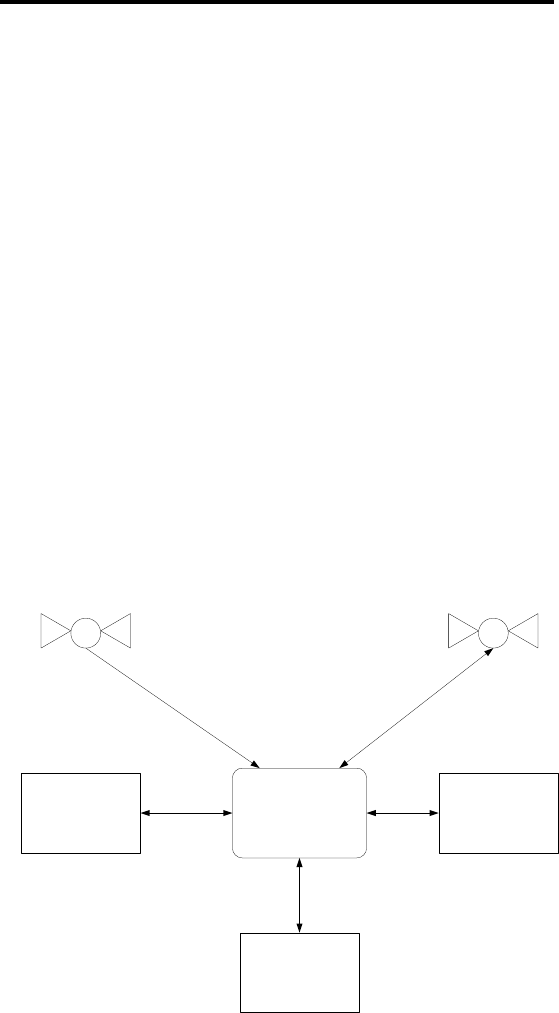
AVIATION RECORDERS
COMPONENT MAINTENANCE MANUAL
AIRBUS IRIDIUM SATCOM SYSTEM
DESCRIPTION AND OPERATION
1. SYSTEM OVERVIEW
Refer to Figure 1. The Airbus Iridium SATCOM System comprises a portion of the aircraft
avionics, or “Aircraft Earth Station” (AES) required to support the "Next Generation
Satellite System" (NGSS) using the Iridium Satellite System as specified in RTCA/DO-
262A.
This system serves as the radio transceiver that provides RF path connectivity with the
satellite(s), and provides the digital data (ISDM) and/or analog voice and/or digital voice
interfaces (ISVM) with other aircraft user subsystems. Its primary functions are: modulation
and demodulation of transmitted and received signals, respectively, signaling and protocol
interactions with corresponding satellites, channel management, and switching and
interconnections with the aircraft and their attached avionics.
The Airbus Iridium SATCOM System provides multiple voice and data communications
functions in the aircraft. The Automated Flight Information Reporting System (AFIRS)
provides a satellite voice and data communications (SATCOM) link with the Public
Switched Telephone Network (PSTN) via the Iridium® satellite network. The system uses a
standard ARINC 741/761 SATCOM interface to the flight crew’s Audio Integrating System
and ARINC 739A Multi-Purpose Control and Display Units (MCDUs) in the cockpit, as well
as providing 3-extension Public Branch Exchange (PBX) capability for up to 2 handsets in
the cabin.
Airbus Irridium
SATCOM System
Operational
User
Maintenance
User
External Aircraft
Systems
Iridium Space
Segment
GPS Space
Segment
Figure 1. Airbus Iridium SATCOM System Operational Concept
Description and Operation
Page 1
Jan. 21/14
23-28-01
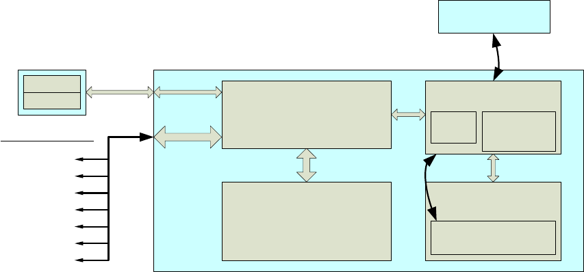
AVIATION RECORDERS
COMPONENT MAINTENANCE MANUAL
AIRBUS IRIDIUM SATCOM SYSTEM
Refer to Figure 2. The Airbus Iridium SATCOM System interfaces to various aircraft
systems to monitor, record, and report the aircraft flight and system data. This data
includes aircraft movement and position reports, Flight Data Monitoring (FDM) data
records, engine and airframe system health and trend records and reports, and monitored
parameter tolerances and exception reports.
The Airbus Iridium SATCOM System provides a dedicated safety-services data channel
with the capability to send and receive standard ACARS messages between the aircraft’s
Air Traffic Service Unit (ATSU) and a safety-services certified terrestrial service provider.
AFIRS Antenna
(Iridium and GPS)
Satellite Data Unit (SDU)
To Aircraft Interfaces
Satellite Control
Module (SCM)RF
Data Acquisition and Power
Module (DAPM)
Interconnects, Conditioning,
Monitoring, Power Supply, Hold-Up
Circuitry
EEPROM
SIM Card RF Mixer Module
(RFMM)
GPS
Module
Iridium
Satellite Data
Modem (ISDM)
Voice Modem Interface
Module (VMIM)
Iridium Satellite Voice
Modem (ISVM)
Modem Control and Interface
Module (MCIM)
System Control, Data and
Telephony Processing, Data Storage
and Retrieval, Communication
Control, BIT
28 VDC Power
ARINC 573/717
ARINC 429
Serial
Ethernet
Discrete
Audio
RF
Figure 2. Airbus Iridium SATCOM System Block Diagram
Description and Operation
Page 2
Jan. 21/14
23-28-01
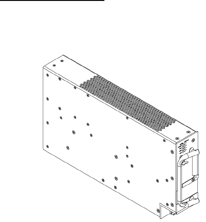
AVIATION RECORDERS
COMPONENT MAINTENANCE MANUAL
AIRBUS IRIDIUM SATCOM SYSTEM
2. SYSTEM ARCHITECTURE
The Airbus Iridium SATCOM System consists of three Line Replaceable Units (LRUs). The
core system components are the Satellite Data Unit (SDU), the SDU Configuration Module
(SCM), the Iridium Antenna, and Coaxial Antenna Cable assembly. Optional components
include Cabin Handset(s) (Wired or Cordless).
A. SATELLITE DATA UNIT (SDU)
Refer to Figure 3. The SDU is an ARINC 600 2MCU electronic enclosure that resides
in the aircraft’s equipment rack. It contains the system intelligence and interface
circuitry for connecting to the various aircraft systems. The SDU also contains Iridium
voice and data modem(s), as well as a GPS receiver.
Figure 3. Satellite Data Unit (SDU) Assembly Drawing
Part Number: 228E5733-00
Description and Operation
Page 3
Jan. 21/14
23-28-01
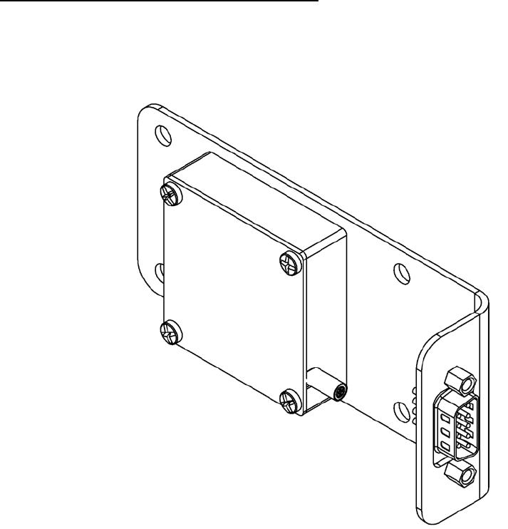
AVIATION RECORDERS
COMPONENT MAINTENANCE MANUAL
AIRBUS IRIDIUM SATCOM SYSTEM
B. SDU CONFIGURATION MODULE (SCM)
Refer to Figure 4. The SCM is a small module that is mounted near the SDU. It uses
an EEPROM to store a copy of the “aircraft personality” information. The SCM also
contains the Iridium SIM card, which provides access to the Iridium satellite network
for the voice communications functionality.
Figure 4. SDU Configuration Module (SCM) Assembly Drawing
Part Number: 418E5733-00
Description and Operation
Page 4
Jan. 21/14
23-28-01
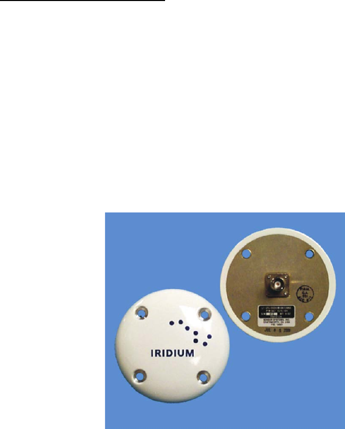
AVIATION RECORDERS
COMPONENT MAINTENANCE MANUAL
AIRBUS IRIDIUM SATCOM SYSTEM
C. IRIDIUM ANTENNA SYSTEM
Refer to Figure 5. The antenna is a Commercial Off-The-Shelf (COTS) unit that is
mounted on the top of the aircraft’s fuselage. It provides satellite connectivity for both
the GPS and Iridium satellite systems.
The Airbus Iridium SATCOM System has a single combined Iridium/GPS RF
connection on the rear interface connector, which is to be connected to a single
combined Iridium/GPS Antenna. The antenna system is comprised of all the
components from the rear interface connector up to, and including, the antenna. The
total gain of the antenna system must be greater than 0 dB at 1626.5 MHz (measured
at the antenna zenith).
Most Iridium antennas have a gain of +3 dBic at the zenith, therefore, the maximum
attenuation in the rest of the antenna system must be less than 3 dB. If an antenna
with a different gain is selected, the maximum loss of the rest of the antenna system
must be adjusted accordingly.
Figure 5. Airbus Iridium SATCOM System Antenna
Drawing Part Number: 009E5733-00
Description and Operation
Page 5
Jan. 21/14
23-28-01
AVIATION RECORDERS
COMPONENT MAINTENANCE MANUAL
AIRBUS IRIDIUM SATCOM SYSTEM
THIS PAGE IS INTENTIONALLY LEFT BLANK
Description and Operation
Page 6
Jan. 21/14
23-28-01

AVIATION RECORDERS
COMPONENT MAINTENANCE MANUAL
AIRBUS IRIDIUM SATCOM SYSTEM
TESTING AND TROUBLESHOOTING
1. GENERAL
This section is not applicable to this CMM.
The Airbus Iridium System components: Satellite Data Unit, p/n: 228E5733-00, and SDU
Configuration Module, p/n: 418E5733-00, have been designated as Level-1 non-field-
repairable Line Replaceable Units. These Airbus Iridium System units should be returned
to L-3 Aviation Recorders Repair Station for all maintenance tasks (i.e. disassembly,
assembly, replacement parts, testing, and return to service certification).
23-28-01
Testing & Fault Isolation
Page 101
Jan. 21/14
AVIATION RECORDERS
COMPONENT MAINTENANCE MANUAL
AIRBUS IRIDIUM SATCOM SYSTEM
THIS PAGE IS INTENTIONALLY LEFT BLANK
23-28-01
Testing & Fault Isolation
Page 102
Jan. 21/14

AVIATION RECORDERS
COMPONENT MAINTENANCE MANUAL
AIRBUS IRIDIUM SATCOM SYSTEM
DISASSEMBLY
1. GENERAL
This section is not applicable to this CMM.
The Airbus Iridium System components: Satellite Data Unit, p/n: 228E5733-00, and SDU
Configuration Module, p/n: 418E5733-00, have been designated as Level-1 non-field-
repairable Line Replaceable Units. These Airbus Iridium System units must be returned to
L-3 Aviation Recorders Repair Station for all maintenance tasks (i.e. disassembly,
assembly, replacement parts, testing, and return to service certification).
Disassembly
Page 301
Jan. 21/14
23-28-01
AVIATION RECORDERS
COMPONENT MAINTENANCE MANUAL
AIRBUS IRIDIUM SATCOM SYSTEM
THIS PAGE IS INTENTIONALLY LEFT BLANK
Disassembly
Page 302
Jan. 21/14
23-28-01

AVIATION RECORDERS
COMPONENT MAINTENANCE MANUAL
AIRBUS IRIDIUM SATCOM SYSTEM
CLEANING
1. GENERAL
This section is not applicable to this CMM.
The Airbus Iridium System components: Satellite Data Unit, p/n: 228E5733-00, and SDU
Configuration Module, p/n: 418E5733-00, have been designated as Level-1 non-field-
repairable Line Replaceable Units. These Airbus Iridium System units should be returned
to L-3 Aviation Recorders Repair Station for all maintenance tasks (i.e. disassembly,
assembly, replacement parts, testing, and return to service certification).
Cleaning
Page 401
Jan. 21/14
23-28-01
AVIATION RECORDERS
COMPONENT MAINTENANCE MANUAL
AIRBUS IRIDIUM SATCOM SYSTEM
THIS PAGE IS INTENTIONALLY LEFT BLANK
Cleaning
Page 402
Jan. 21/14
23-28-01

AVIATION RECORDERS
COMPONENT MAINTENANCE MANUAL
AIRBUS IRIDIUM SATCOM SYSTEM
CHECK
1. GENERAL
This section is not applicable to this CMM.
The Airbus Iridium System components: Satellite Data Unit, p/n: 228E5733-00, and SDU
Configuration Module, p/n: 418E5733-00, have been designated as Level-1 non-field-
repairable Line Replaceable Units. These Airbus Iridium System units should be returned
to L-3 Aviation Recorders Repair Station for all maintenance tasks (i.e. disassembly,
assembly, replacement parts, testing, and return to service certification).
Check
Page 501
Jan. 21/14
23-28-01
AVIATION RECORDERS
COMPONENT MAINTENANCE MANUAL
AIRBUS IRIDIUM SATCOM SYSTEM
THIS PAGE IS INTENTIONALLY LEFT BLANK
Check
Page 502
Jan. 21/14
23-28-01

AVIATION RECORDERS
COMPONENT MAINTENANCE MANUAL
AIRBUS IRIDIUM SATCOM SYSTEM
REPAIR
1. GENERAL
This section is intended to contain information required to restore a worn or damaged part
to a serviceable condition. However, the Airbus Iridium SATCOM System is a completely
solid-state device that does not contain any electro-mechanical moving parts.
The Airbus Iridium SATCOM System consists of a Satellite Data Unit (SDU) and SDU
Configuration Module (SCM) line replaceable units (LRUs).
These LRUs have been designed as Level-1 maintenance units that make extensive use
of surface mount technology (SMT). The repair of circuit card assemblies (CCAs)
containing SMT components requires specialized factory equipment, training, and
techniques, therefore, such CCAs are not field-repairable. Only the L-3AR Repair Station,
FAA: LD7R612J; EASA.145.4620 is authorized to repair the Airbus Iridium SATCOM
System components in accordance with L-3AR Factory test, calibration and repair
specifications.
CAUTION: THE AIRBUS IRIDIUM SYSTEM CIRCUIT BOARDS ARE SUSCEPTIBLE
TO ELECTROSTATIC DESTRUCTION. PRIOR TO HANDLING PWAs,
ENSURE PROPER PERSONNEL GROUNDING TECHNIQUES ARE
USED.
ENSURE THAT CARDS ARE PLACED INTO STATIC SHIELDING
CONDUCTIVE BAGS WHEN HANDLING OR STORING.
Repair
Page 601
Jan. 21/14
23-28-01
AVIATION RECORDERS
COMPONENT MAINTENANCE MANUAL
AIRBUS IRIDIUM SATCOM SYSTEM
THIS PAGE IS INTENTIONALLY LEFT BLANK
Repair
Page 602
Jan. 21/14
23-28-01

AVIATION RECORDERS
COMPONENT MAINTENANCE MANUAL
AIRBUS IRIDIUM SATCOM SYSTEM
ASSEMBLY
1. GENERAL
This section is not applicable to this CMM.
The Airbus Iridium System components: Satellite Data Unit, p/n: 228E5733-00, and SDU
Configuration Module, p/n: 418E5733-00, have been designated Level-1 non-field-
repairable Line Replaceable Units. These Airbus Iridium System units must be returned to
the L-3AR Repair Station, FAA: LD7R612J; EASA.145.4620 for service in accordance with
L-3AR Factory assembly specification instructions.
Assembly
Page 701
Jan. 21/14
23-28-01
AVIATION RECORDERS
COMPONENT MAINTENANCE MANUAL
AIRBUS IRIDIUM SATCOM SYSTEM
THIS PAGE IS INTENTIONALLY LEFT BLANK
Assembly
Page 702
Jan. 21/14
23-28-01
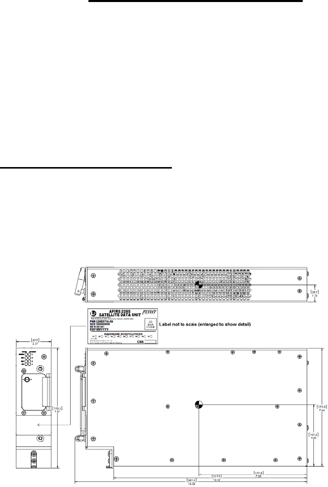
AVIATION RECORDERS
COMPONENT MAINTENANCE MANUAL
AIRBUS IRIDIUM SATCOM SYSTEM
FITS AND CLEARANCES
1. GENERAL
This section provides the Airbus Iridium System specifications and outline and dimensions.
Since the recorder uses solid-state memory recording technology, there are no internal fits
and clearances or torque values normally associated with older technology electro-
mechanical tape recorder units.
2. EQUIPMENT SPECIFICATIONS
This section describes the mechanical specifications of the components of the Airbus
Iridium SATCOM System.
A. SATELLITE DATA UNIT (SDU)
This paragraph describes the mechanical specifications of the Satellite Data Unit
(SDU) refer to Figure 801 for an outline of this component.
1) SDU Outline & Dimensions
The SDU is housed in an ARINC 600 2MCU enclosure, which is designed to be
mounted in a standard ARINC 600 mounting tray.
Figure 801. SDU Outline Drawing (dimensions in [millimeters] and inches)
Description and Operation
Page 801
Jan. 21/14
23-28-01
AVIATION RECORDERS
COMPONENT MAINTENANCE MANUAL
AIRBUS IRIDIUM SATCOM SYSTEM
2) SDU Specifications
Dimensions: 7.81” x 2.27” x 15.02” (198.3mm x 57.7mm x 381.5mm)
Weight: 7.7 lbs. (3.49 kg) Max.
Material/Finish: Aluminum Alloy with Black Polyurethane Finish
Mounting: ARINC 600 2MCU Mounting Tray
Rear Mating Connector: Size 2 ARINC 600 Receptacle
Radiall P/N: NSXN2P201S0004
Maintenance Connector: RJ45 (8P8C) Modular Connector Jack
Flash Card: Compact-Flash® (Type I or Type II)
Environmental &: This information is contained in Appendix C of the
Electrical: Airbus Iridium SATCOM System Installation Manual,
p/n: 165E5733-00.
Description and Operation
Page 802
Jan. 21/14
23-28-01
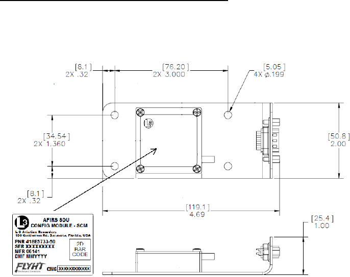
AVIATION RECORDERS
COMPONENT MAINTENANCE MANUAL
AIRBUS IRIDIUM SATCOM SYSTEM
B. SDU CONFIGURATION MODULE (SCM)
This paragraph describes the mechanical specifications of the SDU Configuration
Module (SCM). Refer to Figure 802 for an outline of this component.
1) SCM Outline & Dimensions
Figure 802. SCM Outline Drawing (dimensions in [millimeters] and inches)
2) SCM Specifications
Dimensions: 1.00” x 2.00” x 4.69” (25.4mm x 50.8mm x 119.1mm)
Weight: 0.4 lbs. (0.18 kg) Max.
Material/Finish: Aluminum alloy with clear chromate per
MIL-DTL-5541, Type II, Class 3 on all surfaces.
Environmental &: This information is contained in Appendix C of the
Electrical: Airbus Iridium SATCOM System Installation Manual,
p/n: 165E5733-00.
Description and Operation
Page 803
Jan. 21/14
23-28-01
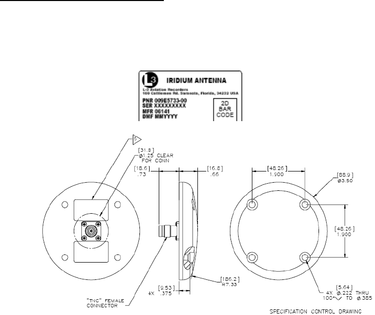
AVIATION RECORDERS
COMPONENT MAINTENANCE MANUAL
AIRBUS IRIDIUM SATCOM SYSTEM
C. IRIDIUM ANTENNA SYSTEM
This paragraph describes the mechanical specifications of the Iridium Antenna. Refer
to Figure 803 for the Outline & Dimension drawing of this component.
1) Iridium Antenna Outline & Dimensions
Figure 803. Iridium Antenna Outline Drawing
(dimensions in [millimeters] and inches)
Description and Operation
Page 804
Jan. 21/14
23-28-01

AVIATION RECORDERS
COMPONENT MAINTENANCE MANUAL
AIRBUS IRIDIUM SATCOM SYSTEM
2) Iridium Antenna Specifications
The Iridium SATCOM System Antenna is a passive antenna designed to cover
the frequency range from 1565 MHz to 1626.5 MHz for Iridium transmit / receive
operations and GPS reception. It is a low-profile, circular device that can be
mounted directly to the aircraft fuselage. This antenna connects to the Iridium
SDU through a coaxial cable.
Weight (Typical)
0.170 kg (6 oz.)
Overall Dimensions (Typical)
Height: 16.8 mm (0.66 inches)
Diameter: 89 mm (3.5 inches)
Manufacturer’s Specification Reference Number
Drawing 009E5733-00, Revision – Iridium Antenna – Passive, 1565 – 1626.5
MHz, RHCP – refer to Figure 5.
Iridium SATCOM System Supplier Equipment Specification,
Document No. 905-E5750-07, Revision –
Environmental Specifications
The Iridium SATCOM System antenna meets the environmental requirements of
RTCA DO-262A where applicable as referenced in Document No. 905-E5809-
42, Revision A.
Testing was performed to DO-160F, MIL-STD-810, EN-60068, ISO-2669, and
the applicable ABDs unless otherwise noted.
Temperature: -55 C (-67 F); to +85 C (+185 F)
Altitude: -100 to +55,000 FT
Vibration: 10 G’s (DO-160D/E F2-AB)
Description and Operation
Page 805
Jan. 21/14
23-28-01
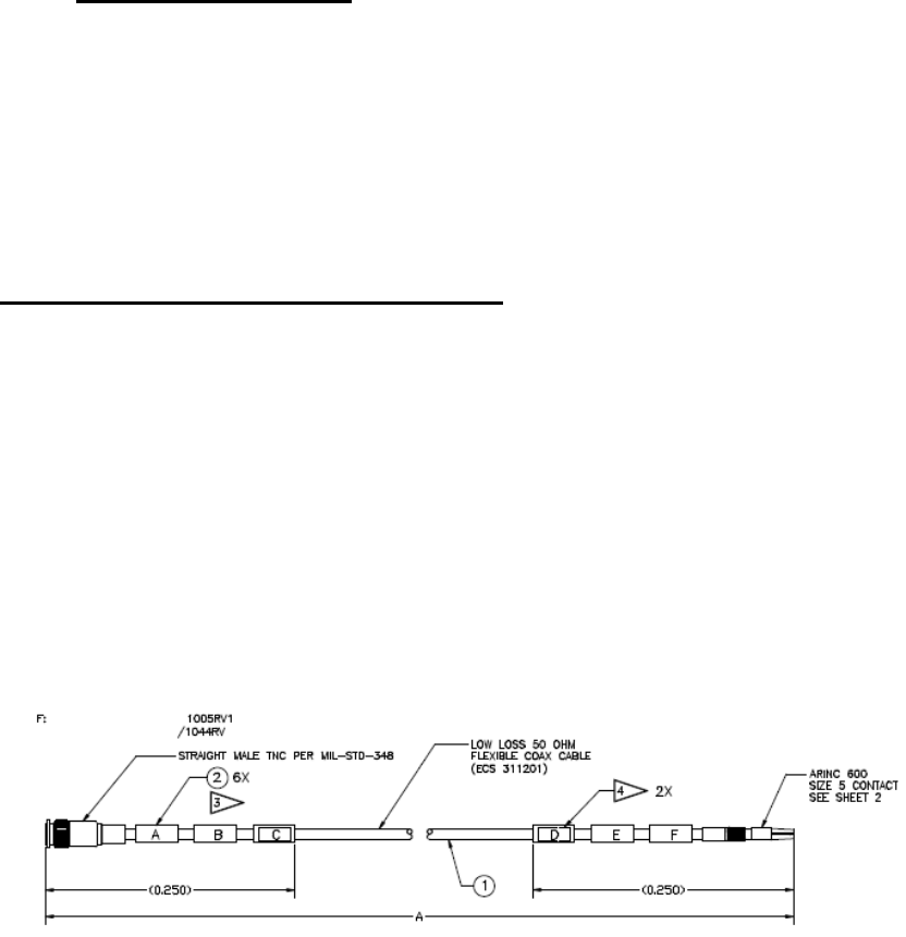
AVIATION RECORDERS
COMPONENT MAINTENANCE MANUAL
AIRBUS IRIDIUM SATCOM SYSTEM
Electrical Specifications
Frequency: 1616.0 – 1625.5 MHz
VSWR: ≤ 1.5:1
Impedance: 50-Ohms
Polarization: RHCP
• Axial Ratio: ≤ 3.0 db @ zenith
• Power Handling: 60 Watts CW
D. COAXIAL ANTENNA CABLE ASSEMBLY
Refer to Figure 804. The Iridium SATCOM System Coaxial Cable is an RF Cable
designed to cover the frequency range from 1565 MHz to 1626.5 MHz for Iridium
transmit / receive operations and GPS reception. It is a low-loss, aircraft-grade cable
that will be mounted in the aircraft fuselage. This cable provides the interconnection
between the Iridium SATCOM System Satellite Data Unit and the Iridium Antenna.
The Coaxial Cable has an ARINC Size 5 coaxial contact installed on one end and a
TNC male connector installed on the other.
There are three possible lengths for this Coaxial Cable. They are designated by the
last two digits of the part number (01, 02 or 03) as listed below:
1) Coaxial Antenna Outline & Dimensions
Figure 804. Coaxial Antenna Cable Outline Drawing
(dimensions in [millimeters] and inches)
Description and Operation
Page 806
Jan. 21/14
23-28-01

AVIATION RECORDERS
COMPONENT MAINTENANCE MANUAL
AIRBUS IRIDIUM SATCOM SYSTEM
2) Iridium Antenna Specifications
Weight (Typical)
• 024E5733-01 - 1.633 kg (57.6 oz)
• 024E5733-02 – 1.497 kg (52.8 oz)
• 024E5733-03 – 1.470 kg (51.8 oz)
Overall Dimensions (Typical)
• Length:
024E5733-01 – 11.3 m (445.0 inches)
024E5733-02 – 10.2 m (402.0 inches)
024E5733-03 – 9.95 m (392.0 inches)
• Diameter: 8.1 mm (0.317 inches)
Manufacturer’s Specification Reference Number
• Drawing 024E5733-00, Revision B; Iridium Antenna Coax Cable – see
Figure 804.
• Iridium SATCOM System Supplier Equipment Specification,
Document No. 905-E5750-07, Revision L.
Environmental Specifications
The Iridium SATCOM System Coaxial Cable meets the environmental
requirements of RTCA DO-262A where applicable as described in Document
No. 905E5836-42. Testing was performed to DO-160F, EN 4604, EN 3475, and
the applicable ABDs unless otherwise noted.
Description and Operation
Page 807
Jan. 21/14
23-28-01
AVIATION RECORDERS
COMPONENT MAINTENANCE MANUAL
AIRBUS IRIDIUM SATCOM SYSTEM
THIS PAGE IS INTENTIONALLY LEFT BLANK
Description and Operation
Page 808
Jan. 21/14
23-28-01

AVIATION RECORDERS
COMPONENT MAINTENANCE MANUAL
AIRBUS IRIDIUM SATCOM SYSTEM
SPECIAL TOOLS, FIXTURES AND EQUIPMENT
1. GENERAL
The Airbus Iridium System components, SDU p/n: 228E5733-00 and SCM p/n: 418E5733-
00) have been designated as Level-1 non-field-repairable Line Replaceable Units. There
are no special tools, fixtures and test equipment for Level-1 maintenance for the Airbus
Iridium System units. These units must be returned to L-3 Communications for all
maintenance tasks (i.e. disassembly, assembly, replacement parts, testing, and return to
service certification).
Special Tools and Test Equipment
Page 901
Jan. 21/14
23-28-01
AVIATION RECORDERS
COMPONENT MAINTENANCE MANUAL
AIRBUS IRIDIUM SATCOM SYSTEM
THIS PAGE IS INTENTIONALLY LEFT BLANK
Special Tools and Test Equipment
Page 902
Jan. 21/14
23-28-01

AVIATION RECORDERS
COMPONENT MAINTENANCE MANUAL
AIRBUS IRIDIUM SATCOM SYSTEM
ILLUSTRATED PARTS LIST
1. GENERAL
The Airbus Iridium System components: Satellite Data Unit, p/n: 228E5733-00 and SDU
Configuration Module, p/n: 418E5733-00, have been designated as Level-1 non-field-
repairable Line Replaceable Units. The Airbus Iridium System units should be returned to
L-3 Communications for all maintenance tasks (i.e. disassembly, assembly, replacement
parts, testing, and return to service certification).
Illustrated Parts List
Page 1001
Jan. 21/14
23-28-01
AVIATION RECORDERS
COMPONENT MAINTENANCE MANUAL
AIRBUS IRIDIUM SATCOM SYSTEM
THIS PAGE IS INTENTIONALLY LEFT BLANK
Illustrated Parts List
Page 1002
Jan. 21/14
23-28-01