L3 Technologies AIS Shipboard AIS User Manual manual
L-3 Communications Shipboard AIS manual
UserManual.wiki
>
L3 Technologies
>
AIS User Manual
manual
Navigation menu
Upload a User Manual
Namespaces
Wiki Guide
HTML
PDF
Info
Views
User Manual
Discussion / Help
Navigation

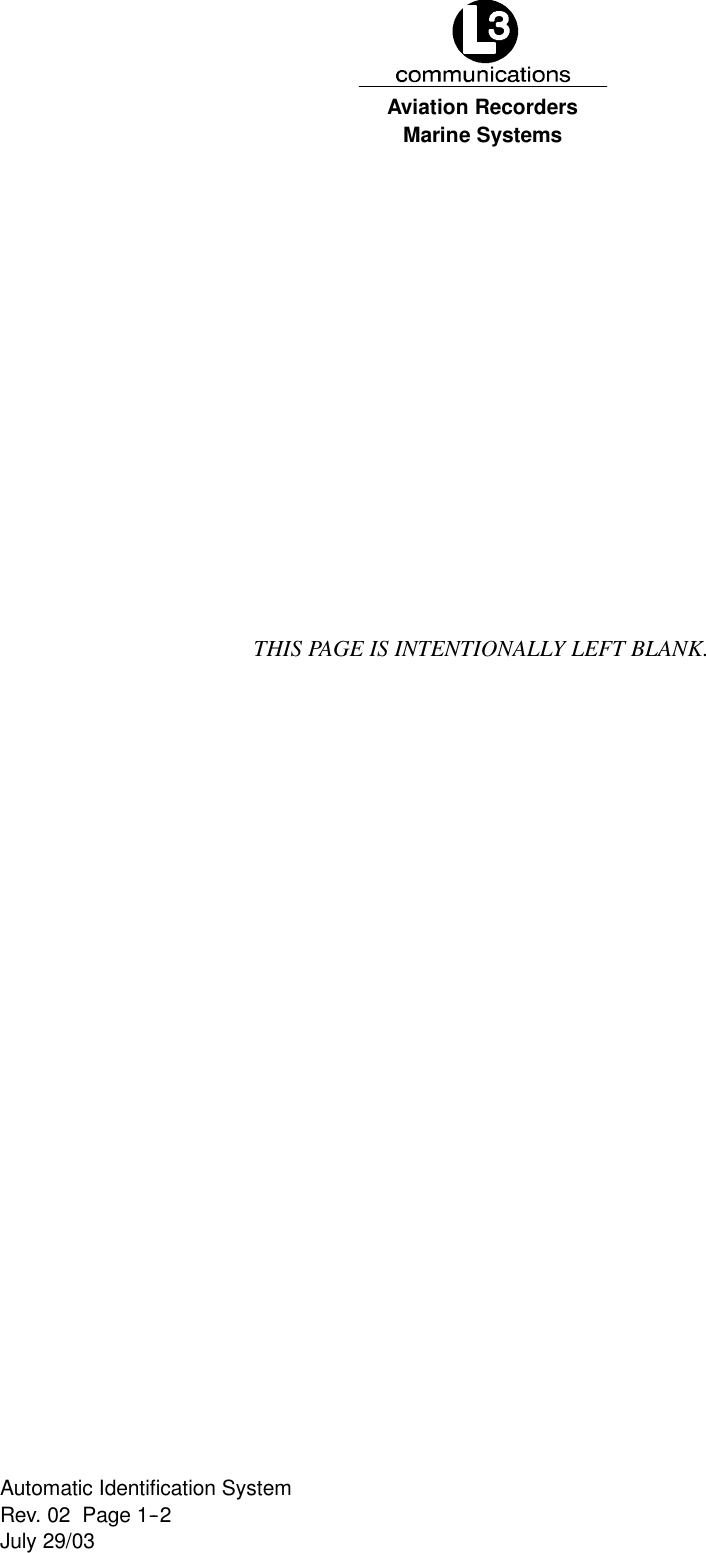
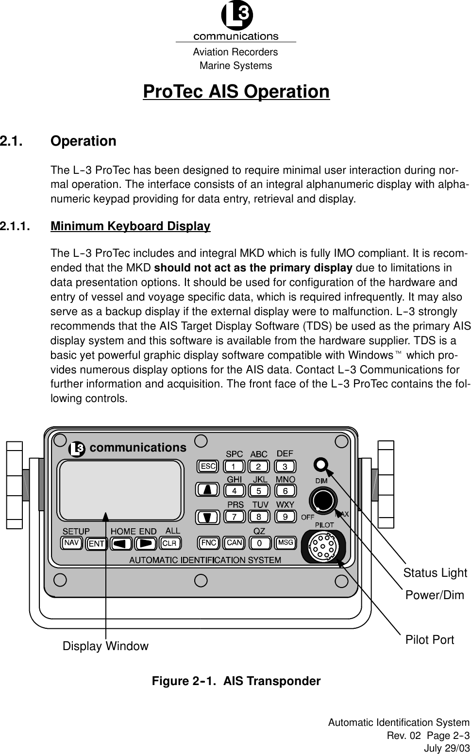
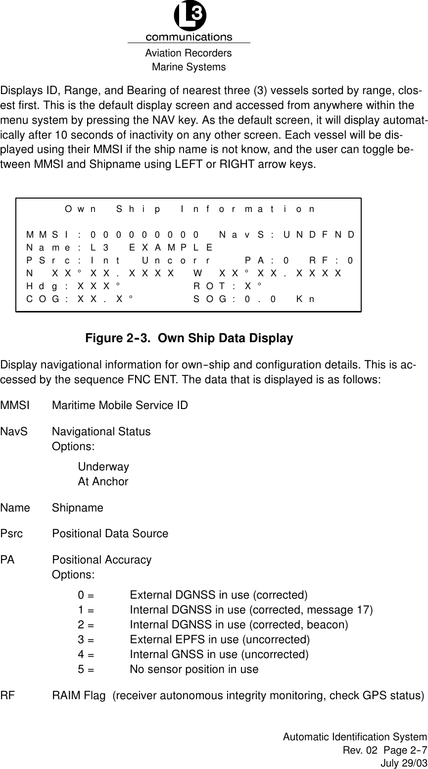
![Marine SystemsAviation RecordersRev. 02 Page 1--12July 29/03Automatic Identification SystemFDimensions of ship -- to nearest meter.FLocation on ship where reference point for position reports is located.FType of position fixing device -- various options from differential GPS toundefined.FDraught of ship -- 1/10 meter to 25.5 meters [note “air--draught” is not pro-vided].FDestination -- 20 characters are provided.1.3.9. AIS FrequenciesThe International Telecommunications Union World Radio Conference in 1997 desig-nated two VHF radio frequencies: 161.975 MHz (AIS1, or channel 87B) and 162.025MHz (AIS2, or channel 88B) for AIS. In the US, the first channel is owned by Mari-TEL, a public coast station operator, and the second by the federal government. TheUSCG signed a Memorandum of Agreement with MariTEL for use of AIS 1, and hasauthority from the National Telecommunications and Information Administration touse both AIS1 and AIS 2 US--wide for AIS operation. The USCG has asked the Fed-eral Communications Commission to authorize any US vessel to operate AIS onthese two channels under its existing ship station license. The FCC released a No-tice authorizing operation of AIS under a ship’s existing station license.](https://usermanual.wiki/L3-Technologies/AIS/User-Guide-354123-Page-22.png)
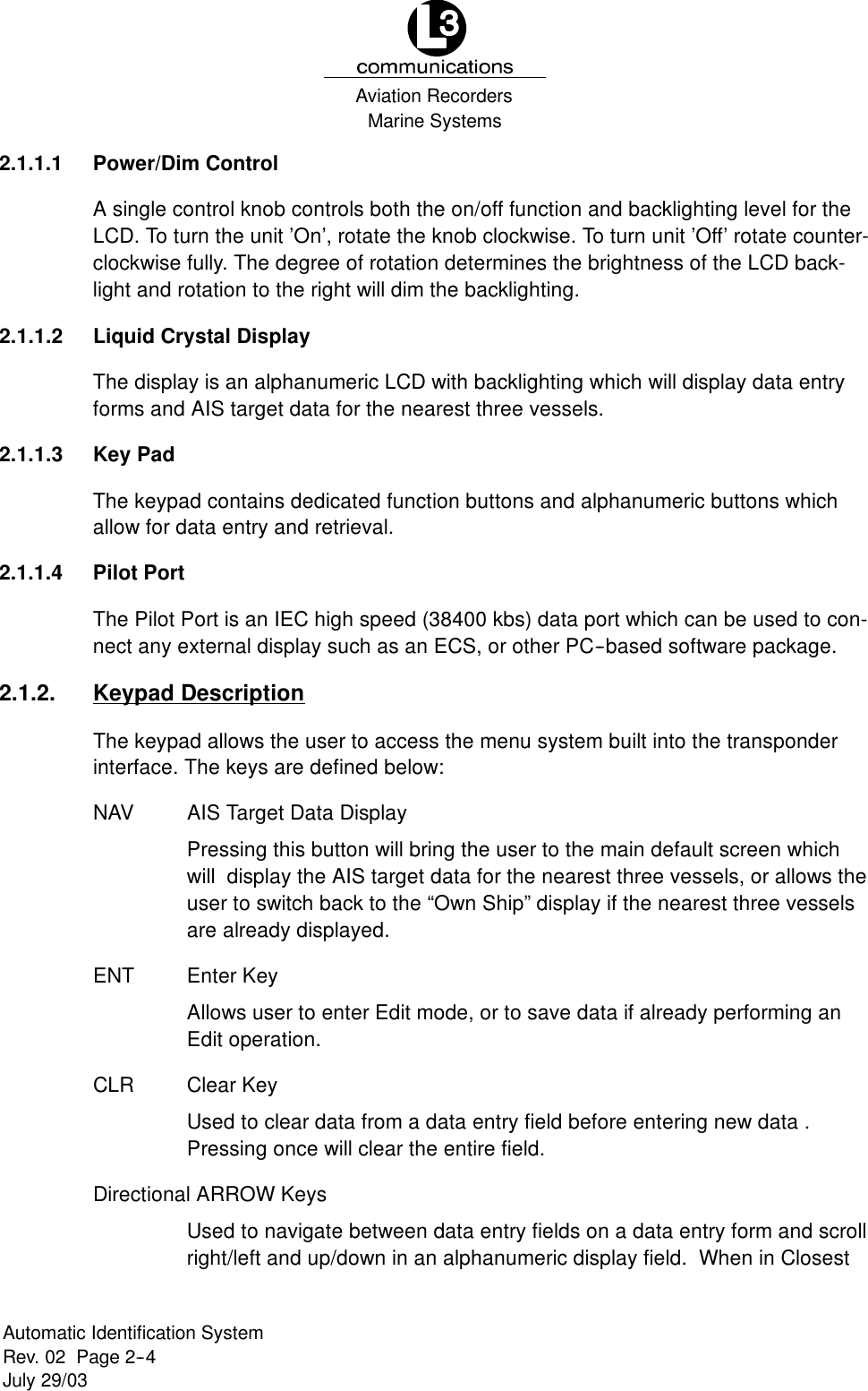
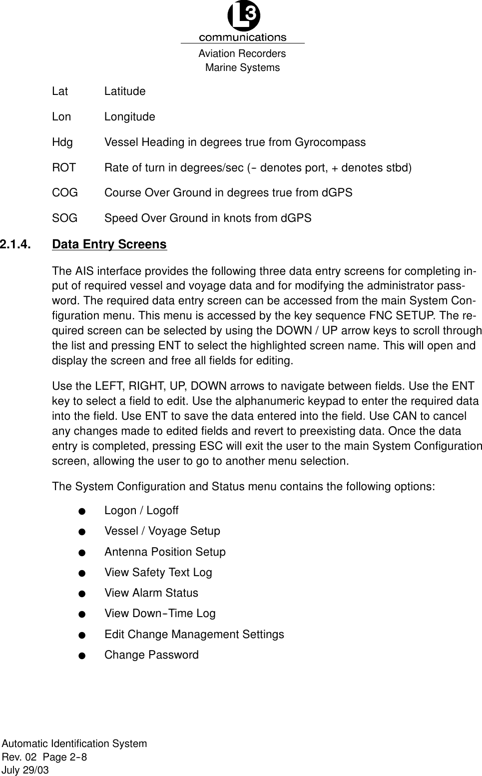


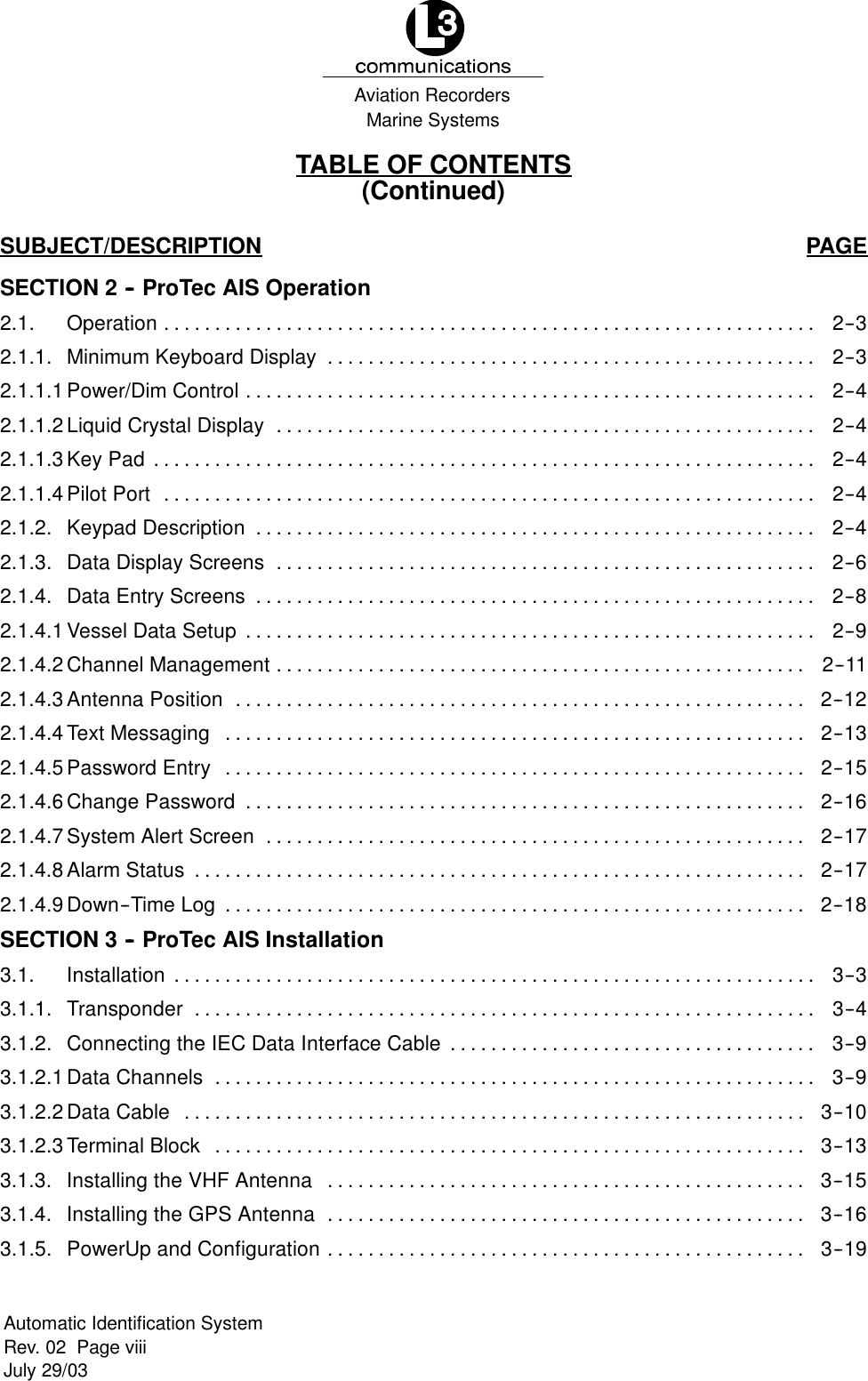
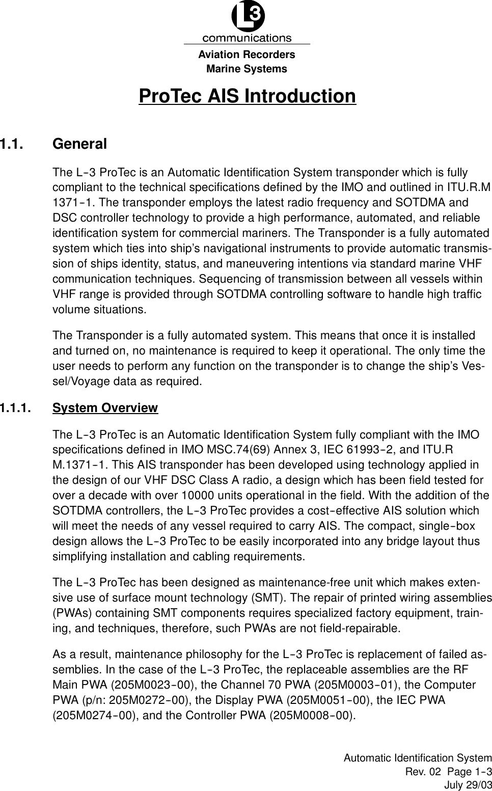
![Marine SystemsAviation RecordersRev. 02 Page 3--12July 29/03Automatic Identification System12--24 VDCBLACK (--)RED (+)GREEN (BIIT 1)WHITE (BIIT 2)GPSANTVHFANTPL 259CONN. TNCCONN.RG59 COAX.RG8X COAX.CABLE GROUP 1111222122531323NC414245152661627NC819299203010213118WHITE/BLUEBLUE/WHITESHIELDWHITE/ORANGEORANGE/WHITESHIELDWHITE/GREENGREEN/WHITESHIELDCABLE SHIELD[NO CONNECT]WHITE/BROWNBROWN/WHITESHIELDWHITE/GREYGREY/WHITESHIELDRED/BLUEBLUE/REDSHIELDCABLE SHIELD[NO CONNECT]RED/ORANGEORANGE/REDSHIELDRED/GREENGREEN/REDSHIELDRED/BROWNBROWN/REDSHIELDCABLE SHIELD12345678910111213141516171819202122232425262728293031CABLE GROUP 2 CABLE GROUP 3IEC DATACABLE(31 PIN)RATE OF TURNNMEA 0183RS 422 CH 2HEADINGNMEA 0183RS 422 CH 3PC/EXT APP.NMEA 0183RS 422 CH 4RXTXBABAPOSITIONNMEA 0183RS 422 CH 1TXBABAABTXBABARXTXECDIS/ARPANMEA 0183RS 422 CH 5BATXBARXLONG RANGENMEA 0183RS 422 CH 8TXOpen = FailShort = PassNote: Akarn Relay OutputFigure 3--8. IEC Data Cable External Wiring Diagram](https://usermanual.wiki/L3-Technologies/AIS/User-Guide-354123-Page-58.png)