L3 Technologies AIS Shipboard AIS User Manual manual
L-3 Communications Shipboard AIS manual
manual
P/N: 165M0014--00July 29/03
Rev. 02
ProTec
AUTOMATIC IDENTIFICATION SYSTEM
HARDWARE
AIS PART NUMBER
AISA1000--00
communications
INSTALLATION AND OPERATION MANUAL

Marine Systems
Aviation Recorders
Rev. 02 Page ii
July 29/03
Automatic Identification System
AIS Hardware I&O Manual 165M0014--00
Rev. 02
July 29/03
The AIS products/software are being exported from the
United States in accordance with the Export Adminis-
tration Regulations ECCN 4D994, No License Re-
quired. Diversion contrary to U.S. law is prohibited. In
accordance with U.S. Law (31 CFR Part 746, and Sup-
plement No.1 to Part 774, and CFR Part 550) resale/re--
export or transfer to the countries identified therein is
prohibited without the prior written consent of the U.S.
Department of Commerce.
This manual contains date sensitive information.
To verify the latest revision level of this manual,
visit our document download site at
http://www.L--3ar.net.
ECopyright 2003 by L-3 Communications.
All rights reserved. No part of this manual may be re-
produced or utilized in any form or by any means, elec-
tronic or mechanical, including photocopying, record-
ing, or by information storage and retrieval system,
without permission in writing.
Inquiries should be addressed to:
L-3 Communications
Aviation Recorders Publications
Vendor Code: 06141
P. O. Box 3041
Sarasota, Florida 34230
Phone: (941) 371–0811
FAX: (941) 377–5591

Marine Systems
Aviation Recorders
Rev. 02 Page iii
July 29/03
Automatic Identification System
GENERAL
This product and related documentation must be reviewed for familiarization with safety
markings and instructions before operation.
This board was constructed in an ESD (electro–static discharge) protected environment. This is
because most of the semiconductor devices used in this board are susceptible to damage by static
discharge.
Depending on the magnitude of the charge, device substrates can be punctured or destroyed by
contact or mere proximity of a static charge. The results can cause degradation of device perfor-
mance, early failure, or immediate destruction.
These charges are generated in numerous ways such as simple contact, separation of materials,
and normal motions of persons working with static sensitive devices.
When handling or servicing equipment containing static sensitive devices, adequate precautions
must be taken to prevent device damage or destruction.
Only those who are thoroughly familiar with industry accepted techniques for handling static sen-
sitive devices should attempt to service circuitry with these devices.
In all instances, measures must be taken to prevent static charge build–up on work surfaces and
persons handling the devices.

Marine Systems
Aviation Recorders
Rev. 02 Page iv
July 29/03
Automatic Identification System
RETURN MATERIAL POLICY
Components and spare parts purchased from L--3 that are discrepant for any of the following reasons may be re-
turned immediately provided the extended value of the parts are in excess of $100.00.
1. Overshipments
Quantity of parts received in excess of quantity specified on purchase order.
2. Wrong Part Numbers
Receipt of parts numbered other than those identified on a customer order where L--3 has not advised the cus-
tomer by purchase order acknowledgment, by telex, or by notification on the shipping document that the received
part is a replacement for the ordered part.
3. Parts Nonconforming to Specifications
If the extended value of the items is less than $100.00, the items are to be scrapped instead of returned. When
this occurs, notification must be sent to L--3 advising: (1) the reason for the rejection; (2) the items are less than
$100.00 in extended value and have been scrapped, and; (3) whether credit or replacement is desired.
If you wish to return material to L--3 for reasons other than warranty returns or those specified above, please contact
an L--3 Account Administrator for authorization before proceeding. A Return Authorization Number will be assigned at
this time. Your request should specify the relevant Return Authorization Number, purchase order number, part num-
ber, quantity and the reason you wish the part returned.
To assist us in processing these items more efficiently, we ask that all returned goods be accompanied by paperwork
that clearly indicates the following:
1. Reason for return.
2. Purchase Order Numbers.
3. Correspondence Reference Number.
4. Return Authorization Number.
4. Copies of returned goods paperwork should be mailed to:
L--3 COMMUNICATIONS CORPORATION
AVIATION RECORDERS DIVISION
P. O. Box 3041
Sarasota, FL 34230--3041
Attn: Tom Meloche / Marine Systems Product Support Department
5. Parts returned under the above conditions should be addressed to:
L--3 COMMUNICATIONS CORPORATION
AVIATION RECORDERS DIVISION
6000 E. Fruitville Road
Sarasota, FL 34232
Attn: SERVICE DEPARTMENT
Component and spare parts purchased from L--3 that have been on the customer’s shelf for more than 10 weeks from
date of receipt; have been installed in a component or on a vessel, are not covered by this procedure. Such parts
may be covered by warranty in which case they should be returned through normal warranty channels.

Marine Systems
Aviation Recorders
Rev. 02 Page v
July 29/03
Automatic Identification System
RETURN OF MATERIAL UNDER WARRANTY
1. Material should be returned to the following address:
L--3 COMMUNICATIONS CORPORATION
AVIATION RECORDERS DIVISION
6000 E. Fruitville Road
Sarasota, FL 34232
Attn: WARRANTY RETURNS
2. For returning overseas shipments, the following customs broker must be used:
L--3 COMMUNICATIONS CORPORATION
AVIATION RECORDERS DIVISION
c/o A.J. Arango
Air Cargo Bldg.
Hoover Blvd.
Tampa Int’l Airport
Tampa, Florida 33634
Tel: (813) 248--9220
Fax: (813) 248--6013
To ensure prompt handling of material returned under warranty, your return order and shipment should clearly
identify the item as a warranty return, and a copy of such return order should accompany the shipment. Status of
warranty in process will be provided by the Warranty Administrator.
3. Warranty claims and warranty return orders pertaining to components and spare parts returned should be
mailed to the following address:
L--3 COMMUNICATIONS CORPORATION
AVIATION RECORDERS DIVISION
P. O. Box 3041
Sarasota, FL 34230--3041
Attn: Marine Systems Warranty Administrator
Tel: (941) 377--5574
Fax: (941) 377--5591
RETURNED GOODS
Goods returned to stock for credit at the request of the Buyer and authorized by the Seller, will be subject to a restock-
ing charge of 10% of the purchase price if notified within 30 days of the order, and 25% of the purchase price if notified
after 30 days of the order.
CANCELLATION CHARGE
Any order wishing to be canceled must be approved by the pertinent Account Administrator and may be accountable
for a cancellation fee of 15%. This cancellation fee shall take into account expenses already incurred and commit-
ments made by L--3.

Marine Systems
Aviation Recorders
Rev. 02 Page vi
July 29/03
Automatic Identification System
THIS PAGE IS INTENTIONALLY LEFT BLANK.

Marine Systems
Aviation Recorders
Rev. 02 Page vii
July 29/03
Automatic Identification System
TABLE OF CONTENTS
AUTOMATIC IDENTIFICATION SYSTEM
SUBJECT/DESCRIPTION PAGE
SECTION 1 -- ProTec AIS Introduction
1.1. General 1--3.................................................................
1.1.1. System Overview 1--3.........................................................
1.1.2. References 1--4..............................................................
1.1.3. Acronyms 1--5................................................................
1.2. Technical Specifications 1--6...................................................
1.3. AIS Description 1--8...........................................................
1.3.1. Compact Design 1--8..........................................................
1.3.2. Integral Minimum Keyboard Display (MKD) 1--8..................................
1.3.3. Integral GPS 1--8.............................................................
1.3.4. Data Interface 1--8............................................................
1.3.5. Equipment List 1--9...........................................................
1.3.6. Operational Modes 1--10......................................................
1.3.6.1Autonomous and Continuous 1--10.............................................
1.3.6.2Assigned 1--10...............................................................
1.3.6.3Polled 1--10..................................................................
1.3.6.4Initialization 1--10.............................................................
1.3.7. DSC Functionality 1--11.......................................................
1.3.8. AIS Broadcast Parameters 1--11................................................
1.3.9. AIS Frequencies 1--12.........................................................
1.4. Interface Description 1--13.....................................................
1.4.1. Pilot Systems Input Data and Formats 1--13......................................
1.4.2. Pilot Systems Output Data and Formats 1--14....................................
1.4.3. Pilot Input / Output Port 1--14..................................................
1.4.4. Long Range equipment interface 1--15..........................................
1.4.5. Long Range Input Data and Formats 1--15.......................................
1.4.6. Long Range Output Data and Formats 1--16.....................................
1.4.7. Sensor Input Data and Formats 1--18...........................................

Marine Systems
Aviation Recorders
Rev. 02 Page viii
July 29/03
Automatic Identification System
TABLE OF CONTENTS
(Continued)
SUBJECT/DESCRIPTION PAGE
SECTION 2 -- ProTec AIS Operation
2.1. Operation 2--3................................................................
2.1.1. Minimum Keyboard Display 2--3................................................
2.1.1.1Power/Dim Control 2--4........................................................
2.1.1.2Liquid Crystal Display 2--4.....................................................
2.1.1.3Key Pad 2--4.................................................................
2.1.1.4Pilot Port 2--4................................................................
2.1.2. Keypad Description 2--4.......................................................
2.1.3. Data Display Screens 2--6.....................................................
2.1.4. Data Entry Screens 2--8.......................................................
2.1.4.1Vessel Data Setup 2--9........................................................
2.1.4.2Channel Management 2--11....................................................
2.1.4.3Antenna Position 2--12........................................................
2.1.4.4Text Messaging 2--13.........................................................
2.1.4.5Password Entry 2--15.........................................................
2.1.4.6Change Password 2--16.......................................................
2.1.4.7System Alert Screen 2--17.....................................................
2.1.4.8Alarm Status 2--17............................................................
2.1.4.9Down--Time Log 2--18.........................................................
SECTION 3 -- ProTec AIS Installation
3.1. Installation 3--3...............................................................
3.1.1. Transponder 3--4.............................................................
3.1.2. Connecting the IEC Data Interface Cable 3--9....................................
3.1.2.1Data Channels 3--9...........................................................
3.1.2.2Data Cable 3--10.............................................................
3.1.2.3Terminal Block 3--13..........................................................
3.1.3. Installing the VHF Antenna 3--15...............................................
3.1.4. Installing the GPS Antenna 3--16...............................................
3.1.5. PowerUp and Configuration 3--19...............................................

Marine Systems
Aviation Recorders
Rev. 02 Page ix
July 29/03
Automatic Identification System
LIST OF FIGURES
FIGURE TITLE PAGE
Figure 1--1. AIS Transponder 1--6...................................................
Figure 2--1. AIS Transponder 2--3...................................................
Figure 2--2. NAV Display Screens 2--6................................................
Figure 2--3. Own Ship Data Display 2--7..............................................
Figure 2--4. System Configuration Screen 2--9........................................
Figure 2--5. Vessel Data Setup 2--11.................................................
Figure 2--6. Channel Management Settings Screen 2--12...............................
Figure 2--7. Antenna Position Screen 2--12...........................................
Figure 2--8. Antenna Position Measurements 2--13....................................
Figure 2--9. Safety Text Message 2--14...............................................
Figure 2--10. Safety Text Review Screen 2--15..........................................
Figure 2--11. Password Entry Screen 2--16.............................................
Figure 2--12. Password Change Screen 2--17..........................................
Figure 2--13. System Alert Screen 2--17...............................................
Figure 2--14. Alarm Status Screen 2--18...............................................
Figure 2--15. Down--Time Log Screen 2--18............................................
Figure 3--1. AIS Transponder Interconnection Diagram 3--3.............................
Figure 3--2. AIS Transponder O&D Drawing with Trunion Bracket 3--5....................
Figure 3--3. AIS Transponder O&D Drawing 3--6.......................................
Figure 3--4. AIS Transponder Power Cable 3--7.......................................
Figure 3--5. Pilot Port Cable 3--8.....................................................
Figure 3--6. AIS Transponder IEC Data Cable 3--10....................................
Figure 3--7. IEC Data Cable Interconnect Diagram 3--11................................
Figure 3--8. IEC Data Cable External Wiring Diagram 3--12.............................
Figure 3--9. AIS Transponder Antenna Diagram 3--17..................................
Figure 3--10. AIS Transponder Rear View 3--18.........................................
Figure 3--11. AIS Transponder MKD 3--19.............................................
Figure 3--12. System Configuration Screen 3--20.......................................
Figure 3--13. Vessel Data Setup 3--20.................................................
Figure 3--14. Antenna Position 3--22..................................................
Figure 3--15. Calculating Antenna Position 3--23........................................
Figure 3--16. Transponder Interconnection Diagram 3--24................................

Marine Systems
Aviation Recorders
Rev. 02 Page x
July 29/03
Automatic Identification System
LIST OF TABLES
TABLE TITLE PAGE
Table 1--1. AIS Parts List 1--9.......................................................
Table 1--2. Pilot System High--Speed Input Data Formats 1--13..........................
Table 1--3. Pilot System High--Speed Output Data Formats 1--14........................
Table 1--4. Long Range Input Data and Formats 1--16..................................
Table 1--5. Long Range Output Data and Formats 1--17................................
Table 1--6. Sensor Input Data and Formats 1--18......................................
Table 2--1. Vessel Type Codes 2--10.................................................
Table 2--2. Password Type Menu Screen Access 2--15.................................
Table 3--1. Data Channels 3--9......................................................
Table 3--2. IEC Cable and Junction Box Pinouts 3--14..................................
Table 3--3. Vessel Type Codes 3--21.................................................

Marine Systems
Aviation Recorders
Rev. 02 Page 1--1
July 29/03
Automatic Identification System
SECTION 1
ProTec
AUTOMATIC IDENTIFICATION SYSTEM (AIS)
INTRODUCTION

Marine Systems
Aviation Recorders
Rev. 02 Page 1--2
July 29/03
Automatic Identification System
THIS PAGE IS INTENTIONALLY LEFT BLANK.

Marine Systems
Aviation Recorders
Rev. 02 Page 1--3
July 29/03
Automatic Identification System
ProTec AIS Introduction
1.1. General
The L--3 ProTec is an Automatic Identification System transponder which is fully
compliant to the technical specifications defined by the IMO and outlined in ITU.R.M
1371--1. The transponder employs the latest radio frequency and SOTDMA and
DSC controller technology to provide a high performance, automated, and reliable
identification system for commercial mariners. The Transponder is a fully automated
system which ties into ship’s navigational instruments to provide automatic transmis-
sion of ships identity, status, and maneuvering intentions via standard marine VHF
communication techniques. Sequencing of transmission between all vessels within
VHF range is provided through SOTDMA controlling software to handle high traffic
volume situations.
The Transponder is a fully automated system. This means that once it is installed
and turned on, no maintenance is required to keep it operational. The only time the
user needs to perform any function on the transponder is to change the ship’s Ves-
sel/Voyage data as required.
1.1.1. System Overview
The L--3 ProTec is an Automatic Identification System fully compliant with the IMO
specifications defined in IMO MSC.74(69) Annex 3, IEC 61993--2, and ITU.R
M.1371--1. This AIS transponder has been developed using technology applied in
the design of our VHF DSC Class A radio, a design which has been field tested for
over a decade with over 10000 units operational in the field. With the addition of the
SOTDMA controllers, the L--3 ProTec provides a cost--effective AIS solution which
will meet the needs of any vessel required to carry AIS. The compact, single--box
design allows the L--3 ProTec to be easily incorporated into any bridge layout thus
simplifying installation and cabling requirements.
The L--3 ProTec has been designed as maintenance-free unit which makes exten-
sive use of surface mount technology (SMT). The repair of printed wiring assemblies
(PWAs) containing SMT components requires specialized factory equipment, train-
ing, and techniques, therefore, such PWAs are not field-repairable.
As a result, maintenance philosophy for the L--3 ProTec is replacement of failed as-
semblies. In the case of the L--3 ProTec, the replaceable assemblies are the RF
Main PWA (205M0023--00), the Channel 70 PWA (205M0003--01), the Computer
PWA (p/n: 205M0272--00), the Display PWA (205M0051--00), the IEC PWA
(205M0274--00), and the Controller PWA (205M0008--00).

Marine Systems
Aviation Recorders
Rev. 02 Page 1--4
July 29/03
Automatic Identification System
When it has been determined that one or more of these assemblies is faulty, the
faulty assembly(ies) should be removed and returned to the Aviation Recorders fac-
tory for repair or replacement. Attempts to repair any of these assemblies will void
the warranty. Extreme care should be used when handling these assemblies.
For repair service, ship units to:
L--3 Communications, Aviation Recorders
6000 East Fruitville Road
Sarasota, FL 34232 USA
Attn: Repair Department
Tel: (941) 377--5558
Fax #: (941) 377--5585
CAUTION: THE L--3 ProTec CIRCUIT BOARDS ARE SUSCEPTIBLE TO
ELECTROSTATIC DESTRUCTION (ESD). PRIOR TO HANDLING
PWAs, ENSURE PROPER PERSONNEL GROUNDING TECH-
NIQUES ARE USED. ENSURE THAT CARDS ARE PLACED INTO
STATIC SHIELDING CONDUCTIVE BAGS WHEN HANDLING OR
STORING.
1.1.2. References
IMO Resolution MSC.74(69), Annex 3, Recommendation on Performance Standards
for an Universal Shipborne Automatic Identification Systems (AIS)
IMO SN/Circ. 227, Guidelines for the INstallation of a Shipborne Automatic Identifi-
cation System (AIS)
International Telecommunications Union Sector for Radio Communications (ITU--R)
Recommendation M.1371--1, Technical Characteristics for a Universal Shipborne
Automatic Identification System Using Time Division Multiple Access in the Maritime
Mobile Band.
IEC 61993--2 Ed.1, Maritime Navigation and Radiocommunication Requirements --
Automatic Identification Systems (AIS) -- Part 2: Class A shipborne Equipment of the
Universal Automatic Identification System (AIS) -- Operational and Performance Re-
quirements, Methods of Test and Required Test Results
IEC 60945 Ed. 4, Maritime Navigation and Radiocommunication Equipment and
Systems -- General Requirements -- Methods of Testing and Required Test Results.
IALA Recommendation on AIS Shore Stations and Networking Aspects Relating to
the AIS Service, Edition 1.0, September 5, 2002

Marine Systems
Aviation Recorders
Rev. 02 Page 1--5
July 29/03
Automatic Identification System
1.1.3. Acronyms
ABM Addressed Binary Message
ABK Ackowledgement Message
ACA AIS Channel Assigment
ACK Ackowledgement Message
BBM Broadcast Binary Message
COG Course Over Ground
DGPS Differential Global Positiioning System
GGA Global Positioning Fix Data
GLL Geographic Position, Latitude/Longitude
GPS Global Positiioning System
GSA GPS DOP and Active Satellites
GSV GPS Satellites in View
HDG Heading, Deviation & Variation
HDT Heading, True
IEC International Electrotechnical Commission
IMO International Maritime Organization
LRF Long Range Function
LFI Long Range Interrogation
MMSI Maritime Mobile Service ID
NMEA National Marine Electronics Association
RAIM Receiver Autonomous Integrity Monitoring
RMC Recommended Minimum Data for GPS
ROT Rate of Turn
SOG Speed Over Ground
SOTDMA Self Organized Time Division Multiple Access
SSD Station Static Data
TDS Target Display Software
TXT Status/Indication Message
VBW Dual Ground/Water Speed
VDO VHF Data--link Own--vessel Message
VSD Voyage Static Data
VTG Track Made Good and Ground Speed
ZDA Date and Time
Marine Systems
Aviation Recorders
Rev. 02 Page 1--6
July 29/03
Automatic Identification System
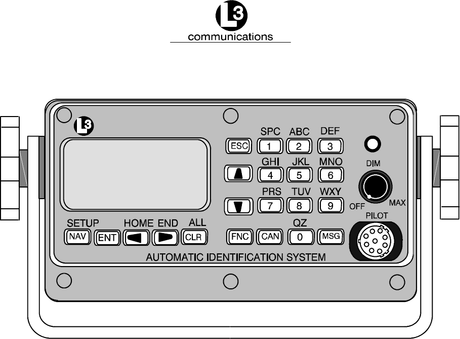
NOTE: 1. Front Panel Mating Connectors
Pilot Port -- L3 PN: 063--98--02113
TYCO PN: 206485--1
communications
Figure 1--1. AIS Transponder
1.2. Technical Specifications
Standards IMO MSC.74(69) Annex 3, IEC 61993--2, ITU.R.M.1371--1
Ship reporting capacity
2250 reports per minute, 4500 reports per minute on two channels
TDMA Transmitter
TX Frequency: 156.025 MHz -- 162.025 MHz, manual/automatic setting
Transmitter Power: 2 W, 12.5 W manual/automatic selection

Marine Systems
Aviation Recorders
Rev. 02 Page 1--7
July 29/03
Automatic Identification System
TDMA Receiver
RX Frequency: 156.025 MHz -- 162.025 MHz, 2 channels
RX1: Default CH87B (161.975 MHz), manual/automatic setting
RX2: Default CH88B (162.025 MHz), manual/automatic setting
Channel Spacing: 25 kHz and 12.5 kHz
DSC Receiver
RX Frequency: CH70 (156.525 MHz)
Internal GPS Receiver
12 Channel, UTC Synchronization Jitter (time between slot start and transmitter on):
±100 μs
Navigational data
COG/SOG, ROT, POS, Heading from external sources
Display
Integral MKD with 160 x 64 Dots backlit LCD
INTERFACE
Input ABM,ACA,ACK,AIR,BBM,DTM,GBS,GGA,GLL,GNS,HDT,
OSD,
SSD, RMC, ROT, VBW, VSD, VTG
Output ABK, VDO, VDM, ACA, ACS, ALR, LRF, LR1, LR2, LR3, TXT
Power Supply
12--24 VDC nominal, complies with IEC 60945
Power Supply requirements, 2.5--5 A, 115/230 VAC with Converter
Environment
IEC 60945 for Protected Environment
Frequency
VHF Marine Band

Marine Systems
Aviation Recorders
Rev. 02 Page 1--8
July 29/03
Automatic Identification System
1.3. AIS Description
1.3.1. Compact Design
The completely self--contained L--3 ProTec is the most compact AIS unit available on
the market today with outside dimensions of 6.5” W (16.5 cm) x 3.4” H (8.6 cm) x
7.4” D (18.8 cm). It is easily mounted on any surface using either a trunion bracket
or flush--mount bracket. The data port on the faceplate provides for easy connection
to any external display in either mounting configuration.
1.3.2. Integral Minimum Keyboard Display (MKD)
In line with the compact design, the L--3 ProTec is a single--box design incorporating
an integral MKD which is fully IMO compliant. The interface includes a of 2.58” L (6.5
cm) x 1.16” H (2.9 cm) (160 x 64 Dots) backlit LCD screen for displaying alphanu-
meric text and a multifunction keypad. The closest three vessels within AIS range
will be displayed with each vessel identified by MMSI and ship name and will display
both range and bearing to each vessel.
The interface has been designed to facilitate data entry and retrieval with a minimum
of keystrokes. It also includes a Pilot port designed to allow any user to quickly and
easily attach a portable AIS--compatible display system directly to the AIS trans-
ponder for display of the AIS data. This display system can consist of any system
which recognizes the NMEA AIS string whether it’s installed on a handheld PC, lap-
top PC, or dedicated display.
1.3.3. Integral GPS
The L--3 ProTec includes an internal GPS receiver card. The internal GPS provides
timing data required for synchronization of transmission. By specifications, ship posi-
tional information in NMEA format is to be fed to the transponder from the ships ex-
ternal electronic position indicating system through the supplied data cable. The in-
ternal GPS requires a dedicated GPS antenna to be mounted on the superstructure
and the appropriate connections are supplied on the transponder unit back panel.
1.3.4. Data Interface
Each transponder will be delivered with an IEC--specified NMEA standard data cable
required to interface to ship’s sensors and external display. The description of this
interface cable is given in the Installation Section of this manual. The standard kit
includes an eight (8) ft. (2.5 meters) cable and a terminal block to facilitate the final
linkup to the ship’s navigational instruments.

Marine Systems
Aviation Recorders
Rev. 02 Page 1--9
July 29/03
Automatic Identification System
1.3.5. Equipment List
The Standard AIS Installation Kit includes the following equipment:
FTransponder Unit with Trunion OR Flush Mount
FIEC NMEA Data Cable
FTerminal Block (for data interface)
FPower Cable
FInstallation Manual and parts kit
In order to complete the installation, the following items will be required.
FGPS Antenna with coaxial cable
FVHF Antenna with coaxial cable
FGyro Interface (if gyro output is not NMEA)
FDGPS Interface (if ships DGPS output is not NMEA)
Table 1--1. AIS Parts List
Component Part Number
Transponder AISA1000--00
Trunion Mount 0780019011
Flush Mount 0010019002
IEC Cable 024M0088--00
Power Cable 024M0086--00
Pilot Port Cable 024M0099--00
12V DC Power Supply
(AC/DC Power Converter) 0810006015

Marine Systems
Aviation Recorders
Rev. 02 Page 1--10
July 29/03
Automatic Identification System
1.3.6. Operational Modes
The ProTec AIS is designed to operate in each of three modes: Autonomous and
Continuous, Assigned and Polled which are defined below.
1.3.6.1 Autonomous and Continuous
This is the default mode. The ProTec AIS will determine its own schedule for trans-
mission of position and identification and will automatically resolve scheduling con-
flicts with other stations using the Self Organized Time Division Multiple Access
(SOTDMA) methodology.
1.3.6.2 Assigned
The ProTec will automatically switch to assigned mode when it is commanded by a
competent authority, such as a base or repeater station, to transmit on a specific
transmission schedule. In this mode, the ProTec allocates the defined slots and be-
gins transmitting on these slots. It will continue to transmit in these slots with a zero
slot time--out and a zero slot offset, until those slots have been removed from the
transmission schedule. The assigned slots use the SOTDMA access scheme, with
the time--out value set to the assigned slot time--out. The assignment terminates
when the slot time--out reaches zero of any assigned slot, and the ProTec returns to
autonomous and continuous mode.
1.3.6.3 Polled
The ProTec AIS will transmit a response to DSC interrogation messages from a ship
or competent authority and respond back on the same channel without interfering
with either of the other two modes. When an automatic response is required, trans-
mitted responses will be made on channel 70 unless the unit is instructed to transmit
on another channel. The ProTec is inhibited from transmitting on the AIS 1 and AIS
2 channels. If and when frequency channels other than channel 70 are used for
DSC transmissions, the receive capability of TDMA operations should not be
impaired more than it would be if all DSC messages were transmitted on channel
70.
1.3.6.4 Initialization
The ProTec AIS will enter into an Initialization mode at Power--Up during which it will
monitor the TDMA channels for one minute. During this initialization period, a dy-
namic directory of all users in the system will be created which includes user ID’s,
slot assignments, positions, and other transmitted data. After this initialization period
of 1 minute, the ProTec will enter the required operational mode and begin transmis-
sion of the AIS data on the required schedule.

Marine Systems
Aviation Recorders
Rev. 02 Page 1--11
July 29/03
Automatic Identification System
1.3.7. DSC Functionality
The Assigned and Polled operational modes are activated through a DSC message
transmitted by the competent authority. In order to provide for this, the ProTec AIS
contains a dedicated DSC receiver that is tuned to channel 70. DSC messages
originating from shore stations of competent authorities will define regional AIS fre-
quencies, regions of coverage, required transmission schedule and/or interrogation
request. The ProTec AIS will respond back to such DSC interrogations on the fre-
quency specified in a manner such that it does not interfere with the TDMA transmis-
sions by interleaving the transmission between TDMA transmissions. The DSC re-
sponse will be made after a random delay of 0 -- 20 secs provided the signaling
channel is clear and the TDMA transmissions are not interrupted.
1.3.8. AIS Broadcast Parameters
A Class A AIS unit broadcasts the following information every 2 to 10 seconds while
underway, and every 3 minutes while at anchor at a power level of 12.5 watts. The
information broadcast includes:
FMMSI number -- unique referenceable identification.
FNavigation status
FSpeed over ground -- 1/10 knot resolution.
FPosition accuracy -- differential GPS.
FLongitude -- to 1/10000 minute and Latitude -- to 1/10000 minute.
FCourse over ground -- relative to true north to 1/10th degree.
FTrue Heading -- 0 to 359 degrees derived from heading sensor.
FTime stamp -- The universal time to nearest second that this information
was generated.
In addition, the Class A AIS unit broadcasts the following information every 6
minutes:
FMMSI number -- same unique identification used above, links the data
above to described vessel.
FIMO number -- unique referenceable identification (related to ship’s
construction).
FRadio call sign -- international call sign assigned to vessel, often used on
voice radio.
FName -- Name of ship, 20 characters are provided.
FType of ship/cargo -- there is a table of possibilities that are available.

Marine Systems
Aviation Recorders
Rev. 02 Page 1--12
July 29/03
Automatic Identification System
FDimensions of ship -- to nearest meter.
FLocation on ship where reference point for position reports is located.
FType of position fixing device -- various options from differential GPS to
undefined.
FDraught of ship -- 1/10 meter to 25.5 meters [note “air--draught” is not pro-
vided].
FDestination -- 20 characters are provided.
1.3.9. AIS Frequencies
The International Telecommunications Union World Radio Conference in 1997 desig-
nated two VHF radio frequencies: 161.975 MHz (AIS1, or channel 87B) and 162.025
MHz (AIS2, or channel 88B) for AIS. In the US, the first channel is owned by Mari-
TEL, a public coast station operator, and the second by the federal government. The
USCG signed a Memorandum of Agreement with MariTEL for use of AIS 1, and has
authority from the National Telecommunications and Information Administration to
use both AIS1 and AIS 2 US--wide for AIS operation. The USCG has asked the Fed-
eral Communications Commission to authorize any US vessel to operate AIS on
these two channels under its existing ship station license. The FCC released a No-
tice authorizing operation of AIS under a ship’s existing station license.

Marine Systems
Aviation Recorders
Rev. 02 Page 1--13
July 29/03
Automatic Identification System
1.4. Interface Description
1.4.1. Pilot Systems Input Data and Formats
The input data and formats are shown in Table 1--2, and the details of the sentences
can be found in IEC 61162--1.
Table 1--2. Pilot System High--Speed Input Data Formats
Data IEC 61162--1 Sentences
Normal Access -- Parameter Entry
Static station information
-- (Vessel name)
-- (Call sign)
-- Antenna location
-- Length and beam
SSD -- Station Static Data
-- (not used, field sets to null by MKD)
-- (not used, field sets to null by MKD)
-- used to set the antenna location for the
MKD external GPS only (saved in MKD
memory)
Voyage Information
-- Vessel type and cargo category
-- Navigational status
-- Draught, max. actual static
-- Destination
-- ETA date and time
-- Regional application flags
VSD -- Voyage Static Data
Long Range Acknowledgement
External manual LR acknowledgement LRF -- Long Range Function
Initiate VHF Data Link Broadcasts
Safety messages ABM -- Addressed Binary Message
BBM -- Broadcast Binary Message
Binary messages ABM -- Addressed Binary Message
BBM -- Broadcast Binary Message
Interrogation message AIR -- AIS Interrogation Information
Channel Setting
Channel assignment message (set frequency) ACA -- AIS Channel Assignment Message
BIIT Input
Alarm / indication acknowledgement ACK -- Acknowledgement Message
Own Station Settings Queries
Query messages AIQ, ACA -- Query AIS Channel Assignment
AIQ, SSD -- Query Station Static Data
AIQ, VSD -- Query Voyage Static Data

Marine Systems
Aviation Recorders
Rev. 02 Page 1--14
July 29/03
Automatic Identification System
1.4.2. Pilot Systems Output Data and Formats
The output data and formats are shown in Table 1--3, and the details of the sen-
tences can be found in IEC 61162--1.
Table 1--3. Pilot System High--Speed Output Data Formats
Data IEC 61162--1 Sentences
Prepared by AIS Transponder
Notification that a session initiated by messages
ABM, BBM, ACA, AIR is terminated ABK -- Acknowledgement Message
AIS Own--ship broadcast data (all transmissions
available) VDO -- VHF Data--link Own--vessel Message
Query response messages ACA -- AIS Channel Assignment
SSD -- Station Static Data
VSD -- Voyage Static Data
BIIT Results
AIS equipment status ALR -- Alarm Message
TXT -- Status / Indication Message
Received from Long Range Equipment
LR Interrogation LRI -- Long Range Interrogation
LR Function identification LRF -- Long Range Function
Received on VHF Data Link by AIS Transponder
All VDL AIS messages received
-- Broadcast or
-- Addressed to own station
VDM -- VHF Data Link Message
1.4.3. Pilot Input / Output Port
The Pilot input/output port is a part of the AIS Class A stations. If the installation of
the AIS equipment is such that a pilot cannot connect his Personal Pilot Unit (PPU)
with a reasonable length of cable, an extension cable must be installed with a con-
nector located on the bridge such that the PPU can be connected on the normal
working position of the port.

Marine Systems
Aviation Recorders
Rev. 02 Page 1--15
July 29/03
Automatic Identification System
The Pilot input/output port defined by IEC 61193--2 for connections of ship’s pilot
equipment shall, if fitted, be connected using the pilot port cable, p/n: 024M0099--00.
The Pilot input/output port meets the requirement of IEC 61162--2 and is terminated
as follows:
FTX A is connected to Pin 1
FTX B is connected to Pin 4
FRX A is connected to Pin 5
FRX B is connected to Pin 6
FShield is connected to Pin 9
1.4.4. Long Range equipment interface
The Long Range reply can be set in either:
Fautomatic mode (AUTO)
Fmanual mode L--3 ProTec (MANUAL)
Fmanual mode external application (EXT APPL).
The Long Range reply, when in AUTO mode, is made as soon as a request is re-
ceived on the Long Range communication port.
The Officer of the Watch must approve the Long Range replay when in MANUAL
mode, by a means of pressing a keyboard button on the L--3 ProTec before the re-
ply is performed.
The Long Range reply, when in EXT APPL mode, is made by the L--3 ProTec upon
reception of confirmation / acknowledgement from the external application via the
high--speed ports. The external application acknowledges the interrogation by re-
turning the LRF sentence (updated with reply information).
1.4.5. Long Range Input Data and Formats
The input data and formats are in the form of two Long Range interrogation sen-
tences, LRI and LRF, refer to Table 1--4.
FThe LRI --sentence contains the information needed to determine if a reply
needs to be constructed.
FThe LRF--sentence identifies the information items that are being re-
quested. Details of each sentence can be found in IEC 61162--1.

Marine Systems
Aviation Recorders
Rev. 02 Page 1--16
July 29/03
Automatic Identification System
Table 1--4. Long Range Input Data and Formats
Data IEC 61162--1 Sentences
Long Range Interrogation
Type of request:
-- Geographic area request
-- AIS transponder request
LRI -- Long Range Interrogation
Long Range Function identification
Requestor MMSI and Name
Request for:
-- Ship’s name, call sign and IMO number (A)
-- Date and time of message composition (B)
-- Position (C)
-- Course over ground (E)
-- Speed over ground (F)
-- Destination and ETA (I)
-- Draught (O)
-- Ship / Cargo (P)
-- Ship’s length, breadth and type (U)
-- Number of persons on board (W)
LRF -- Long Range Function
1.4.6. Long Range Output Data and Formats
The output data and formats are in the form of four Long Range reply sentences,
LRF, LR1, LR2, and LR3, refer to Table 1--5.
FThe LRF sentence provides the “Function Reply Status” for the requested
information. Following is a list of “Function Reply Status” characters with
the status:
2 = Information available and provided in the following LR1, LR2, and LR3
sentences.
3 = Information not available from the AIS system.
4 = Information is available but not provided (i.e. restricted access determined
by ship’s master).
FThe LR1 sentence identifies the destination for the reply and contains the
information items requested by the “A” function identification character in
the LRF sentence.

Marine Systems
Aviation Recorders
Rev. 02 Page 1--17
July 29/03
Automatic Identification System
FThe LR2 sentence contains the information items requested by the “B, C,
E, and F” function identification characters in the LRF sentence.
FThe LR3 sentence contains the information items requested by the “I, O,
P, U, and W” function identification characters in the LRF sentence.
Table 1--5. Long Range Output Data and Formats
Data IEC 61162--1 Sentences
Long Range Function identification
Requestor MMSI and Name
Request for:
-- Ship’s name, call sign and IMO number (A)
-- Date and time of message composition (B)
-- Position (C)
-- Course over ground (E)
-- Speed over ground (F)
-- Destination and ETA (I)
-- Draught (O)
-- Ship / Cargo (P)
-- Ship’s length, breadth and type (U)
-- Number of persons on board (W)
LRF -- Long Range Function
MMSI of Responder
MMSI or Requestor
Ship’s name
Ship’s call sign
IMO number
LR1 -- Long Range Response, Line 1
MMSI of Responder
Date and time of message composition
Position
Course over ground
Speed over ground
LR2 -- Long Range Response, Line 2
MMSI of Responder
Destination and ETA
Draught
Ship / Cargo
Ship’s length, breadth and type
Number of persons on board
LR3 -- Long Range Response, Line 3

Marine Systems
Aviation Recorders
Rev. 02 Page 1--18
July 29/03
Automatic Identification System
1.4.7. Sensor Input Data and Formats
The L--3 ProTec Shipborne Class A Transponder supports input data sentences from
various ship sensors, refer to Table 1--6.
Table 1--6. Sensor Input Data and Formats
Sensor Data IEC 61162--1 Sentences
GNSS Positions system:
-- Time of position
-- Latitude /Longitude
-- Accuracy (and integrity status)
Course Over Ground (COG)
Speed Over Ground (SOG)
RAIM Indicator
DTM, GBS, GGA, GLL, GNS, GRS, GSA,
GST,GSV,HDT,RMC,ROT,VBW,VTG,
ZDA
Log Course Over Ground (COG)
Speed Over Ground (SOG)
VBW
Gyro Heading
Rate of Turn (ROT)
HDT, ROT

Marine Systems
Aviation Recorders
Rev. 02 Page 2--1
July 29/03
Automatic Identification System
SECTION 2
ProTec
AUTOMATIC IDENTIFICATION SYSTEM (AIS)
OPERATION

Marine Systems
Aviation Recorders
Rev. 02 Page 2--2
July 29/03
Automatic Identification System
THIS PAGE IS INTENTIONALLY LEFT BLANK.
Marine Systems
Aviation Recorders
Rev. 02 Page 2--3
July 29/03
Automatic Identification System
ProTec AIS Operation
2.1. Operation
The L--3 ProTec has been designed to require minimal user interaction during nor-
mal operation. The interface consists of an integral alphanumeric display with alpha-
numeric keypad providing for data entry, retrieval and display.
2.1.1. Minimum Keyboard Display
The L--3 ProTec includes and integral MKD which is fully IMO compliant. It is recom-
ended that the MKD should not act as the primary display due to limitations in
data presentation options. It should be used for configuration of the hardware and
entry of vessel and voyage specific data, which is required infrequently. It may also
serve as a backup display if the external display were to malfunction. L--3 strongly
recommends that the AIS Target Display Software (TDS) be used as the primary AIS
display system and this software is available from the hardware supplier. TDS is a
basic yet powerful graphic display software compatible with Windowstwhich pro-
vides numerous display options for the AIS data. Contact L--3 Communications for
further information and acquisition. The front face of the L--3 ProTec contains the fol-
lowing controls.
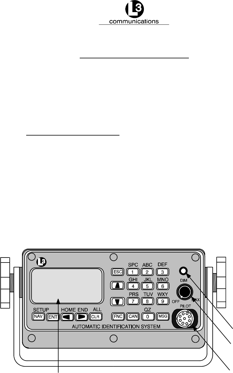
communications
Power/Dim
Status Light
Pilot Port
Display Window
Figure 2--1. AIS Transponder

Marine Systems
Aviation Recorders
Rev. 02 Page 2--4
July 29/03
Automatic Identification System
2.1.1.1 Power/Dim Control
A single control knob controls both the on/off function and backlighting level for the
LCD. To turn the unit ’On’, rotate the knob clockwise. To turn unit ’Off’ rotate counter-
clockwise fully. The degree of rotation determines the brightness of the LCD back-
light and rotation to the right will dim the backlighting.
2.1.1.2 Liquid Crystal Display
The display is an alphanumeric LCD with backlighting which will display data entry
forms and AIS target data for the nearest three vessels.
2.1.1.3 Key Pad
The keypad contains dedicated function buttons and alphanumeric buttons which
allow for data entry and retrieval.
2.1.1.4 Pilot Port
The Pilot Port is an IEC high speed (38400 kbs) data port which can be used to con-
nect any external display such as an ECS, or other PC--based software package.
2.1.2. Keypad Description
The keypad allows the user to access the menu system built into the transponder
interface. The keys are defined below:
NAV AIS Target Data Display
Pressing this button will bring the user to the main default screen which
will display the AIS target data for the nearest three vessels, or allows the
user to switch back to the “Own Ship” display if the nearest three vessels
are already displayed.
ENT Enter Key
Allows user to enter Edit mode, or to save data if already performing an
Edit operation.
CLR Clear Key
Used to clear data from a data entry field before entering new data .
Pressing once will clear the entire field.
Directional ARROW Keys
Used to navigate between data entry fields on a data entry form and scroll
right/left and up/down in an alphanumeric display field. When in Closest

Marine Systems
Aviation Recorders
Rev. 02 Page 2--5
July 29/03
Automatic Identification System
Vessel (default) screen, the Left or Right Arrow Keys will allow the user to
toggle between the Ship Name display and the MMSI screen. (The MMSI
screen will always be displayed for a vessel if the ship name is not known.
FNC Function Key
Used as the initial key in a key sequence to access the various secondary
functions of the interface.
CAN Cancel Key
Used to cancel any edit made in a data entry field and revert data back to
preexisting data.
MSG Message Key
Used to access the text messaging window, in order to send Safety Text
Messages.
ESC Escape Key
Will bring user up one level on the menu system.
The blue text above some identify the secondary definitions for each button. These
secondary definitions are activated by pressing of the FNC button in a key se-
quence.
SETUP Enters the system configuration menu system.
HOME Returns cursor to start position in a data entry field
END Returns cursor to end position in a data entry field
ALL Will clear all contents of a data entry field when preceded by the FNC key.
The alphanumeric keypad is used to enter both numbers and letters. When alphanu-
meric text entry is expected, the nonnumeric options are presented before the nu-
meric value of the key. For example, the number “2” key provides for entry of “A”,
“B”, and “C”. When the cursor is positioned in a display field location that expects an
alphanumeric character, the first press of the “2” key will result in the display of an
“A”. Another press (in a fairly short time) will cause a “B” to be displayed. The next
press shows a “C”, while the forth press shows a “2”.
Repeated key presses will result in cycling through the character options repeatedly.
When the operator stops pressing keys for longer than the preset timeout, the last
value is retained and the cursor moves to the next location in the field. Pressing a
different key forces acceptance of the last character for the field and moves the cur-
sor along.

Marine Systems
Aviation Recorders
Rev. 02 Page 2--6
July 29/03
Automatic Identification System
FNC--ENT Own Ship display
(NAV Key will also bring up this screen if already showing the Closest Ves-
sel display.)
2.1.3. Data Display Screens
The AIS interface consists of the following display screens each of which is ac-
cessed using the defined key sequence.
NOTE: The letter in the lower right hand corner of the screen de-
picts the type of time that is being indicated. S = slot time,
I = Internal GPS, F = Flywheel, N = Time not available.
Sh i p
***
Ta
DD
rg
-- M
Na m
Own
et
MM
s:
-- Y
e/ MM
Pos
00
YY
0
Y
S
U
IR
nkno
H
G-- NM
wn *
H: MM
BRG
**
:SS I
Sh i p
MMS I
MMS I
Ta
DD
rg
-- M
Na m
000
000
et
MM
s:
-- Y
e/ MM
0000
0000
00
YY
0
Y
S
0
0
IR
1
2
H
G-- NM
0. 00
0. 00
H: MM
BRG
XXX
XXX
:SS I
MMSI 000000000 0. 00 XXX°
°
°
Figure 2--2. NAV Display Screens

Marine Systems
Aviation Recorders
Rev. 02 Page 2--7
July 29/03
Automatic Identification System
Displays ID, Range, and Bearing of nearest three (3) vessels sorted by range, clos-
est first. This is the default display screen and accessed from anywhere within the
menu system by pressing the NAV key. As the default screen, it will display automat-
ically after 10 seconds of inactivity on any other screen. Each vessel will be dis-
played using their MMSI if the ship name is not know, and the user can toggle be-
tween MMSI and Shipname using LEFT or RIGHT arrow keys.
O
MM
Na
SI
me
PS
N
rc
XX
Hd
CO
g:
G:
wn S
:0
:L
00
3
:I
°X
nt
X.
XX
XX
X°
.X
hi p
00
EX
00
AM
U
XX
nc
XX
°
I
0
P
o
nf or
0
LE
Na
rr
WXX
RO
SO
T:
G:
ma t i
vS: U
PA
°X
:0
X.
X°
0. 0
on
NDFN
R
XX
F:
XX
Kn
D
0
Figure 2--3. Own Ship Data Display
Display navigational information for own--ship and configuration details. This is ac-
cessed by the sequence FNC ENT. The data that is displayed is as follows:
MMSI Maritime Mobile Service ID
NavS Navigational Status
Options:
Underway
At Anchor
Name Shipname
Psrc Positional Data Source
PA Positional Accuracy
Options:
0 = External DGNSS in use (corrected)
1 = Internal DGNSS in use (corrected, message 17)
2 = Internal DGNSS in use (corrected, beacon)
3 = External EPFS in use (uncorrected)
4 = Internal GNSS in use (uncorrected)
5 = No sensor position in use
RF RAIM Flag (receiver autonomous integrity monitoring, check GPS status)

Marine Systems
Aviation Recorders
Rev. 02 Page 2--8
July 29/03
Automatic Identification System
Lat Latitude
Lon Longitude
Hdg Vessel Heading in degrees true from Gyrocompass
ROT Rate of turn in degrees/sec (-- denotes port, + denotes stbd)
COG Course Over Ground in degrees true from dGPS
SOG Speed Over Ground in knots from dGPS
2.1.4. Data Entry Screens
The AIS interface provides the following three data entry screens for completing in-
put of required vessel and voyage data and for modifying the administrator pass-
word. The required data entry screen can be accessed from the main System Con-
figuration menu. This menu is accessed by the key sequence FNC SETUP. The re-
quired screen can be selected by using the DOWN / UP arrow keys to scroll through
the list and pressing ENT to select the highlighted screen name. This will open and
display the screen and free all fields for editing.
Use the LEFT, RIGHT, UP, DOWN arrows to navigate between fields. Use the ENT
key to select a field to edit. Use the alphanumeric keypad to enter the required data
into the field. Use ENT to save the data entered into the field. Use CAN to cancel
any changes made to edited fields and revert to preexisting data. Once the data
entry is completed, pressing ESC will exit the user to the main System Configuration
screen, allowing the user to go to another menu selection.
The System Configuration and Status menu contains the following options:
FLogon / Logoff
FVessel / Voyage Setup
FAntenna Position Setup
FView Safety Text Log
FView Alarm Status
FView Down--Time Log
FEdit Change Management Settings
FChange Password

Marine Systems
Aviation Recorders
Rev. 02 Page 2--9
July 29/03
Automatic Identification System
NOTE: Figure 2--4 shows the System Configuration and Status
menu screen as it appears as the user initially enters this
menu. Not shown is the Change Password option.
Sy s t
Lo
Ve
An
Vi
Vi
Vi
Ed
em
go
C
ff
ss
te
el
nn
ew
ew
S
A
ew
it
D
C
onf i
/V
a
oy
Po
af
la
et
rm
ow
ha
n--
n
g
a
s
y
T
M
and
ge
it
S
io
T
St
ex
at
im
gm
e
t
St a
et
n
up
Se
t
us
Lo
Lo
Se
g
tt
tus
tup
g
i ngs
Figure 2--4. System Configuration Screen
2.1.4.1 Vessel Data Setup
The Vessel Data Setup screen allows the user to enter the following information
which is required to be completed during the installation of the AIS.
MMSI: Maritime Mobile Service ID
(Maximum 9 characters)
NavS: Navigational Status. When in field, use down arrows to scroll through
available option and click ENT to select.
IMD#: Official IMO designation ID for vessel
(0 = not available= default)
MaxD: Maximum sailing draft in Meters
(0.1 to 25.5 meters)
Csgn: Radio Callsign
(maximum 7 characters)
Type: Vessel Type
(refer to Table 2--1)
Name: Vessel Name
(maximum 20 characters)
Dest: Name of next Destination
(maximum 20 characters)
ETA: Estimated Time of Arrival
(MMDDHHMM UTC)

Marine Systems
Aviation Recorders
Rev. 02 Page 2--10
July 29/03
Automatic Identification System
Table 2--1. Vessel Type Codes
Special Crafts Other Ships
First Digit Second Digit
50Pilot Boats
51Search and Rescue Vessels
52Tugs
53Port Tenders
54Vessels with anti--pollution
facilities or equipment
55Law Enforcement Vessel
56Spare --for assignment to
local vessels
57Spare --for assignment to
local vessels
58Medical Transport
59Spare --for assignment to
other special vessels
6 Passenger Ships
7 Cargo Ships
8 Tankers
9 Other types of
ships
DG:Dangerous
Goods
HS:Harmful
Substances
MP:Marine Pollunants
0 All ships of this type
1 Carrying DG HS or MP
IMO hazard or polluant
category A
2 Carrying DG HS or MP
IMO hazard or polluant
category B
3 Carrying DG HS or MP
IMO hazard or polluant
category C
4 Carrying DG HS or MP
IMO hazard or polluant
category D
5 Not under command
6 Restricted by her ability
to manuever
7 Constrained by her
draught
8 Spare
9 No additional information
To enter vessel and voyage information, perform the following:
(1) Press the FNC key, press the Setup key. The System Configuration screen will
appear.
(2) Using the down Arrow key, select Vessel / Voyage Setup, and press the ENT
key.
(3) Using all of the arrow keys, highlight an entry point, and press the ENT key.
(4) Enter the data, press the ENT key, and move to the next data entry point.
(5) Press the ESC key to return to the System Configuration screen.

Marine Systems
Aviation Recorders
Rev. 02 Page 2--11
July 29/03
Automatic Identification System
V
MM
IM
SI
O#
CS
Na
gn
me
De
ET
st
A
esse
:0
:0
00
:S
:L
QA
3
:S
:M
AR
MD
l/Vo
0000
EXAM
AS
D®
OT
00
y
0
P
A
--
age
0Na
Ma
LE
Ty
00 H
Set u
vS
xD
:U
:0
pe: 0
HMM®
p
ND
.0
FN
00: 0
D
0
Figure 2--5. Vessel Data Setup
2.1.4.2 Channel Management
This screen is designed for the initial setup for the AIS Transponder channel opera-
tion. The L--3 ProTec Transponder will hold up to eight different channel configura-
tions. The user can set these different configurations at the initial setup; however,
the L--3 ProTec Transponder will acquire the data for a new region once it has en-
tered the region.
For the initial setup perform the following:
(1) Press the FNC key.
(2) Press the Setup key. The System Configuration screen will appear.
(3) Using the down Arrow key, select “Edit Chan Mgmt Settings”, and press the
ENT key. The Channel Management Table Entry screen will appear. (Refer to
Figure 2--6.)
(4) Use the up and down arrow keys and the left and right arrow keys to highlight
an entry point, and press the ENT key.
(5) Enter the data, press the ENT key, and move to the next data entry point.
(6) After all of the data is entered for that region, press the FNC key to save the
data.
(7) If another region is required, press the right arrow key to move to the next
screen and repeat steps (4) through (6).
(8) Press the ESC key to return to the System Configuration screen.

Marine Systems
Aviation Recorders
Rev. 02 Page 2--12
July 29/03
Automatic Identification System
C
NE
SW
:
:
Ch
PL
A:
vl
Sr
FN
c:
C:
MTb
NX
NX
X°
X°
20
:L
87
M
In
¬
tr
Pr
lEn
00
00
.0
.0
B
d:
w0
Tx
nl
v. ®
t
R
M
ry 8
E
E
XX
XX
C
xA
hB
B
MS
Nx
I:
t.
Ac t
X°
X°
00
00
:2
TZ
08
n:
-- --
F
-- --
NC
v
.0
.0
8
--
Bw
Nm
-- --
S
-- --
av
0
--
e
Figure 2--6. Channel Management Settings Screen
2.1.4.3 Antenna Position
This setup provides for data entry of location of the antenna for each of the GPS an-
tennas required for the system. The ’Int’ refers to the antenna dedicated to the AIS’
internal GPS and the ‘Ext’ refers to the antenna dedicated to the ship’s external
GPS. The screen layout is as follows:
A
IN
EX
T
T
D
S
im
ee
nt en
A:
A:
0
0
en
I
si
TU
na P
B:
B:
on
-- R
s
M
o
0
0
i
.
si t i
C
C
n
13
Me
71
on R
:0
:0
te
D
rs
oc
ef
D:
D:
0
0
Figure 2--7. Antenna Position Screen
To enter the antenna position, perform the following:
(Refer to Figure 2--7 and Figure 2--8)
(1) Press the FNC key.
(2) Press the Setup key. The System Configuration screen will appear.
(3) Using the down Arrow key, select “Antenna Position Setup”, and press the ENT
key. The Antenna Position Reference screen will appear.
(4) Use the up and down arrow keys and the left and right arrow keys to highlight
an entry point, and press the ENT key.
(5) Enter the data, press the ENT key, and move to the next data entry point.
(6) Press the ESC key to return to the System Configuration screen.

Marine Systems
Aviation Recorders
Rev. 02 Page 2--13
July 29/03
Automatic Identification System
All dimensions defined below are entered in meters.
A Distance in meters from Forward Perpendicular (FP)
B Distance in meters from After Perpendicular (AP)
C Distance in meters inboard from port side
D Distance in meters inboard from starboard side
A
B
CD
Figure 2--8. Antenna Position Measurements
2.1.4.4 Text Messaging
Text messages include specific addressed messages, broacast messages, and safe-
ty messages. To send a particular type of message perform the steps as described
below:
To send a addressed message, perform the following:
(1) Press MSG key.
(2) Press the down arrow key until the MMSI is highlighted.
(3) Press the ENT key, and enter the MMSI number of the ship to be addressed.
(4) Press the down arrow key to highlight “Mode” and press the ENT key.
(5) Using the down arrow key, highlight “Addressed”, and press the ENT key.
(6) Using the down arrow key, highlight the message portion of the screen, type in
the message.
(7) Press the MSG key to broadcast the message.

Marine Systems
Aviation Recorders
Rev. 02 Page 2--14
July 29/03
Automatic Identification System
To broadcast a message, perform the following:
(1) Press MSG key.
(2) Verify that they MMSI number is all zeros.
(3) If the MMSI is not all zeros, press the down arrow key until the MMSI is high-
lighted.
(4) Press the ENT key, and enter all zeros for the MMSI number.
(5) Press the down arrow key to highlight “Mode” and press the ENT key.
(6) Using the down arrow key, highlight “Broadcast”, and press the ENT key.
(7) Using the down arrow key, highlight the message portion of the screen, type in
the message.
(8) Press the MSG key to broadcast the message.
Sa
MM
MO
TE
Us
fety
SI
DE
:0
:B
T: EX
eMs
Tex
00
ro
00
ad
NTER
gKe
t
0
c
y
Ent
00
as
0
t
MESS
to
ry F
AGE
Send
or m
HERE
Tex t
Figure 2--9. Safety Text Message
To review Safety Text Messages that have been received,
perform the following:
(1) Press the FNC key.
(2) Press the Setup key. The System Configuration screen will appear.
(3) Using the down Arrow key, select “View Safety Text Log”, and press the ENT
key. The Safety Text Review screen will appear.
(4) Use the down left and right arrows to view previous or next messages respec-
tively.
(5) Press the ESC key to return to the System Configuration screen.

Marine Systems
Aviation Recorders
Rev. 02 Page 2--15
July 29/03
Automatic Identification System
***
Br
EX
H
AM
¬f
Saf e
H:
PL
MM
E
or P
ty T
:S
ME
S
SS
rev.
e
M
A
xt R
MS
GE
I:
®fo
evi e
0000
rNe
w**
0000
xt
*
0
Figure 2--10. Safety Text Review Screen
2.1.4.5 Password Entry
Passwords allow the user to change the information contained within the AIS Trans-
ponder. Users with an Administrative password can change any of the information
contained within the AIS Transponder; however, users with a User password, cannot
change the MMSI number, IMO number, Name of the ship, Call Sign, passwords, or
anything contained in the Channel management screen.
NOTE: The default administrative password is L3AIS, and the de-
fault user password is L3USR.
Table 2--2. Password Type Menu Screen Access
Menu Screen Administrative Password User Password
System Configuration Edit All Fields Edit All Fields
Vessel Data Setup Edit All Fields Edit All Fields except
MMSI Number,
IMO Number, Call Sign,
Name of Ship
Channel Management Settings Edit All Fields Read Only
Antenna Position Edit All Fields Edit All Fields
Safety Text Message Edit All Fields Edit All Fields
Safety Text Review Access Allowed Access Allowed
Password Entry Data Entry Allowed Data Entry Allowed
Password Edit Edit All Fields Read Only
System Alert Access Allowed Access Allowed
Alarm Status Access Allowed Access Allowed
Down--Time Log Access Allowed Access Allowed
NOTE: Access denotes the abilitly to view the menu and take ap-
propriate actions for the screen.

Marine Systems
Aviation Recorders
Rev. 02 Page 2--16
July 29/03
Automatic Identification System
To log on perform the following:
(1) Press the FNC key.
(2) Press the Setup key. The System Configuration screen will appear.
(3) Using the down Arrow key, select Logon, and press the ENT key. The System
Password Entry screen will appear.
(4) Press the ENT key, and enter the password, and press the ENT again.
(5) Press the ESC key to return to the System Configuration screen.
To log off perform the following:
(1) Press the FNC key.
(2) Press the Setup key. The System Configuration screen will appear.
(3) Using the down Arrow key, select Logon, and press the ENT key. The user is
now logged off of the AIS Transponder.
Sy
Pas s
Ent e
Us e
st em
wo r d
rP
ESC
Pas
: _______________________
wd t
To C
s
o
o
wo r d
Ena
nt i n
Ent
bl e
ue
ry
Up d t s
Figure 2--11. Password Entry Screen
2.1.4.6 Change Password
NOTE: Only users with an administrative password can change pass-
words
To change the transponder’s access password, perform the following:
(1) Press the FNC key.
(2) Press the Setup key. The System Configuration screen will appear.
(3) Using the down Arrow key, select Change Password, and press the ENT key.
The System Password Change screen will appear.

Marine Systems
Aviation Recorders
Rev. 02 Page 2--17
July 29/03
Automatic Identification System
(4) Enter the new password in both fields, and press the ENT key. This will save
the new password.
(5) Press the ESC key to go back to the System Configuration screen.
Sy
Pa
Ve
ss
ri
Put
st em
wd
fy
:
:
Ne w
Pas
Pwd
s
i
wo r d
nBo
Ch a
th F
nge
ields
Figure 2--12. Password Change Screen
2.1.4.7 System Alert Screen
This screen will appear when a system alert is received. Press the ENT key to ac-
knowledge the alert.
***
***
No v
***
Sy s t
Al ar
al i d
Pr es
em A
m0
COG
sEN
l
3
T
er t
0Ac
info
to
Page
tive
rmat
ACK
***
***
ion
***
Figure 2--13. System Alert Screen
2.1.4.8 Alarm Status
The ProTec AIS unit does not support a “General Failure” alarm since all detected
failures are reported with an explicit discrete alarm message.
To review Safety Text Messages that have been received, perform the
following:
(1) Press the FNC key.
(2) Press the Setup key. The System Configuration screen will appear.

Marine Systems
Aviation Recorders
Rev. 02 Page 2--18
July 29/03
Automatic Identification System
(3) Using the down Arrow key, select “View Alarm Status”, and press the ENT key.
(4) Use the down left and right arrows to view previous or next messages respec-
tively.
(5) Press the ESC key to return to the System Configuration screen.
*
00
00
1
2
00
00
3
4
00
00
5
6
** A
VV
VV
0
0
VV
VV
0
0
VV
VV
0
0
larm
0:
0:
00
00
0:
0:
00
00
0:
0:
00
00
:
:
:
:
:
:
St at
00
00
T
V
00
00
R
R
00
00
R
G
us *
x
SW
Fa
R
x
x
Ch
Ch
x
en
70
F
**
il
Li mi
1
2
Er
Er
E
ai
rr
l
t
r
r
Figure 2--14. Alarm Status Screen
2.1.4.9 Down--Time Log
To review Down--Time Log, perform the following:
(1) Press the FNC key.
(2) Press the Setup key. The System Configuration screen will appear.
(3) Using the down Arrow key, select “View Down--Time Log”, and press the ENT
key.
(4) Use the down arrow to view the down times that are further down the list.
(5) Press the ESC key to return to the System Configuration screen.
**
DD
DD
-- M
-- M
DD-- M
*Do
MM
MM
-- Y
-- Y
MM-- Y
wn -- T
Y
Y
HH
HH
YHH
i
:
:
:
me L
MM
MM
MM
og *
00
00
.0
.0
00. 0
**
M
H
in
rs
Da y
s
s
Figure 2--15. Down--Time Log Screen

Marine Systems
Aviation Recorders
Rev. 02 Page 3--1
July 29/03
Automatic Identification System
SECTION 3
ProTec
AUTOMATIC IDENTIFICATION SYSTEM (AIS)
INSTALLATION

Marine Systems
Aviation Recorders
Rev. 02 Page 3--2
July 29/03
Automatic Identification System
THIS PAGE IS INTENTIONALLY LEFT BLANK.
Marine Systems
Aviation Recorders
Rev. 02 Page 3--3
July 29/03
Automatic Identification System
ProTec AIS Installation
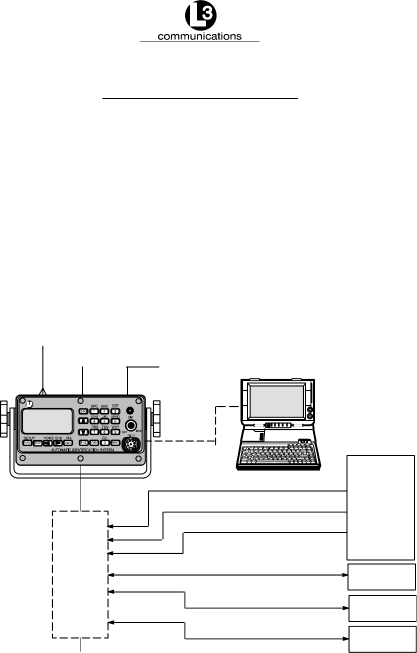
3.1. Installation
The L--3 ProTec Transponder has been designed for easy installation into any exist-
ing bridge layout. Figure 3--1 gives a general representation of the system layout.
Installation can be broken down into 5 distinct operations as follows:
FTransponder
FVHF Antenna
FGPS Antenna
FData Interface
FPowerup and Configuration
Each operation will be discussed in detail below. In regards to 3rd part components
such as VHF and GPS antennas and Gyro interfaces, it is suggested that the
installation procedures suggested by the manufacturer be followed in lieu of these
procedures.
Junction
Box
IEC 61162 HDG, ROT
TRANSPONDER UNIT
IEC 61162 HDG, SOG, COG, ROT, POSN
POSN,SOG,COG
SHIP
SENSORS
(Optional)
RADAR
ECDIS
PILOT/PC
AIS DATA
AIS DATA
AIS DATA
VHF Antenna
150M---W2VN
GPS
24 VDC
Power
PILOT/PC
12---24 VDC
(Optional)
communications
Figure 3--1. AIS Transponder Interconnection Diagram

Marine Systems
Aviation Recorders
Rev. 02 Page 3--4
July 29/03
Automatic Identification System
3.1.1. Transponder
The L--3 ProTec is a single box design which is easily installed into any existing
bridge layout. The compact design requires minimal clearance (refer to Figure 3--2
and Figure 3--3) and can be mounted in a trunion bracket or mounted flush using the
available flush--mount bracket. Install the transponder is as follows:
(1) Mount the transponder in a position which provides easy access to the key-
board and display. If using the trunion bracket, the mount itself may be used to
mark the screw holes on the mounting surface. When locating the transponder,
consider that the IMO mandates that the AIS keyboard and display be easily
accessed from a navigable position on the bridge.
(2) If used, Mount the transponder in the trunion utilizing the trunion knobs pro-
vided, otherwise mount transponder in flush mount bracket.
(3) Locate and mount the terminal block or junction box in a position near the
transponder. The IEC cable provided with the unit is 100 inches (2.5 m) long
and the terminal block should be located to take this into account. Locate the
terminal block in a fashion which allows for easy access to the terminals for
making the connections to required input/output feeds.
(4) Refer to Figure 3--4. Connect the transponder power cable to the power con-
nection on the Transponder and connect to the ships 12--24 Vdc power supply.
The “Red“ lead goes to positive and “Black“ to negative. Ensure proper ground
wire attachment to ships structure.
The other two leads can be used to connect to an external alarm system. This
alarm system can provide an audio and/or visual alarm in the event of an inter-
nal system malfunction, or if the AIS loses power or is turned off.
For steps (5) through (7) refer to Paragraph 3.1.2.
(5) Connect the IEC cable to data port on back of Transponder using J4 connector
provided.
(6) Lead data cables from Gyrocompass data output port and ship’s DGPS data
output port. To terminal block. If an interface adapter must be used to convert
either Gyro output and/or dGPS output to IEC (NMEA 0183) standard, the out-
put from the interfaces should be located as near as possible to the sending
unit (Gyro or dGPS) and the output cables led to the IEC terminal block.
(7) Feed the IEC data cable pigtail to the terminal block.
(8) Do not power up the unit at this time. The transponder should not be powered
up without the VHF antenna connected.
(9) If an external display system is to be connected for display of the AIS target
data, lead the cable from the display unit to the terminal block. (Refer to
Figure 3--5.)
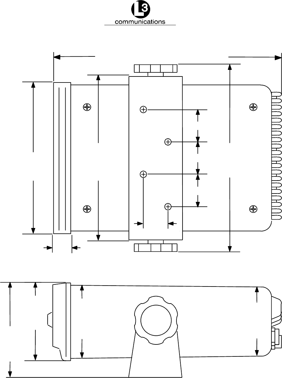
Marine Systems
Aviation Recorders
Rev. 02 Page 3--5
July 29/03
Automatic Identification System
7.23 in. ¦.12
0.625
in.
1.25 in.
1.25 in.
1.25 in.
0.88 in.
7.81 in. ¦.12
6.87 in. ¦.12
6.40 in. ¦.06
3.28 in.
¦.06
3.73 in.
¦.12
3.14 in.
¦.06 2.937 in.
¦.06
80 mm
¦1.5 75 mm
¦1.5
83 mm
¦1.5
95 mm
¦3
174 mm
¦3
163 mm
¦1.5
22 mm
31.75 mm
31.75 mm
31.75 mm
198 mm
¦3
184 mm ¦3
16 mm
Figure 3--2. AIS Transponder O&D Drawing with Trunion Bracket
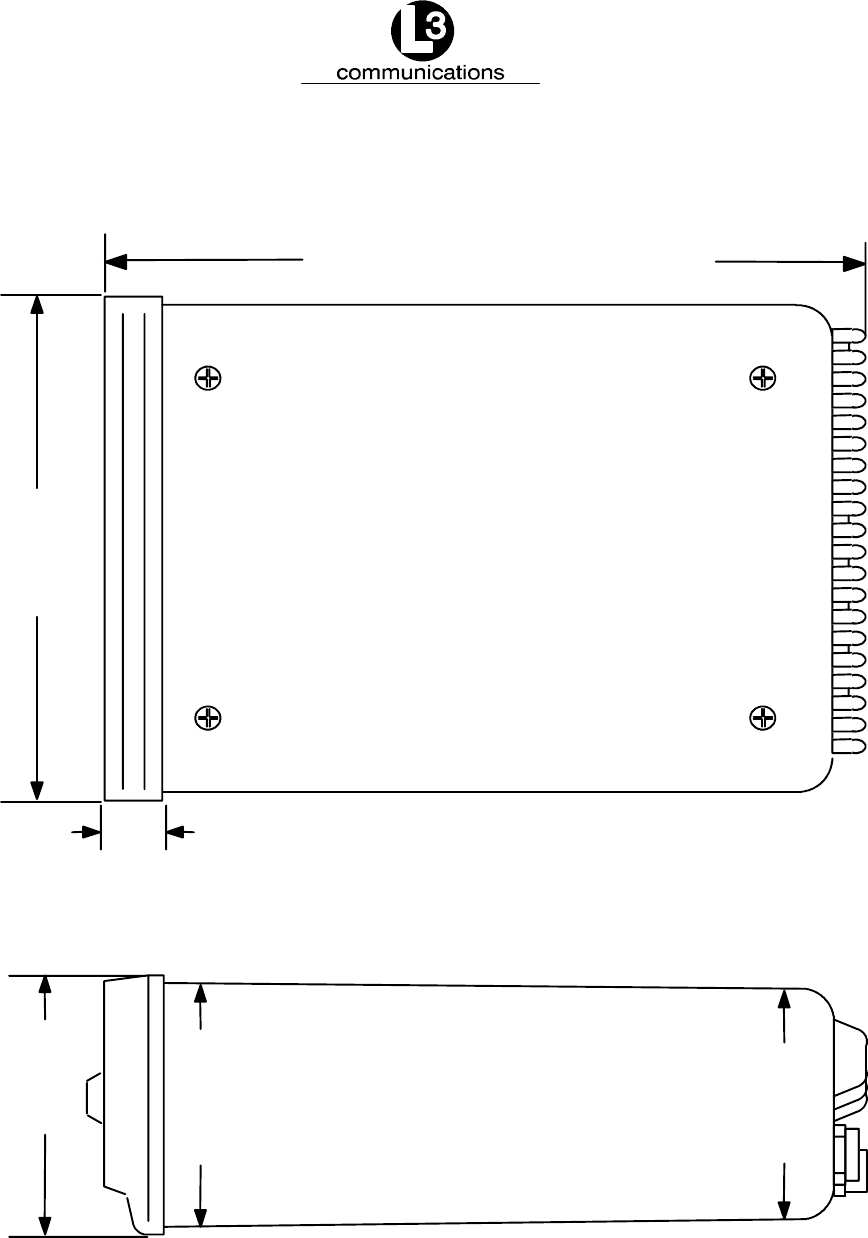
Marine Systems
Aviation Recorders
Rev. 02 Page 3--6
July 29/03
Automatic Identification System
7.23 in. ¦.12
0.625
in.
6.40 ¦.06
184 mm ¦3
163 mm
¦1.5
15.875 mm
3.28 in.
¦.06
3.14 in.
¦.06 2.937 in.
¦.06
80 mm
¦1.5 75 mm
¦1.5
83 mm
¦1.5
Figure 3--3. AIS Transponder O&D Drawing
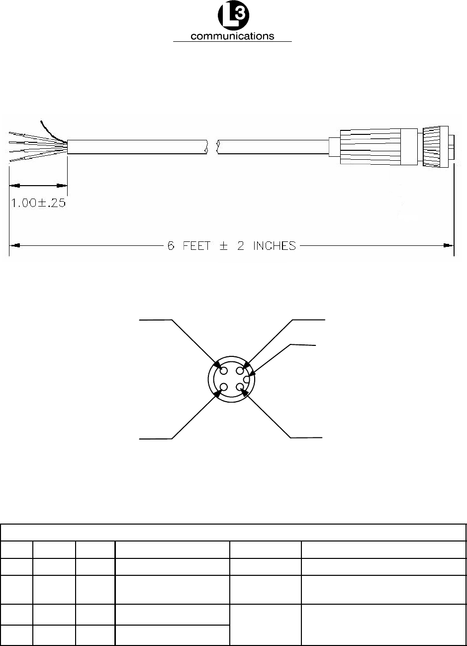
Marine Systems
Aviation Recorders
Rev. 02 Page 3--7
July 29/03
Automatic Identification System
Black
RedGreen
White
ID MARK
1.8 m ¦0.05 m
25 mm
¦6mm
Cable End
Signal Table for “Cable Assembly, Power/BIIT, External”
Line Color Name Description Function Power
1Black B(--) Battery, negative Power return -- --
2Red B(+) Battery, positive Power input +12VDC/5A to +24VDC/2.5A
(nominal voltages)
3Green BIIT 1 BIIT relay, terminal 1 BIIT Status Contact closure
2
2
0
V
D
C
/
2
A
D
C
/
6
0
W
4White BIIT 2 BIIT relay, terminal 2
2
2
0
V
D
C
/
2
A
D
C
/
6
0
W
maximum
Figure 3--4. AIS Transponder Power Cable
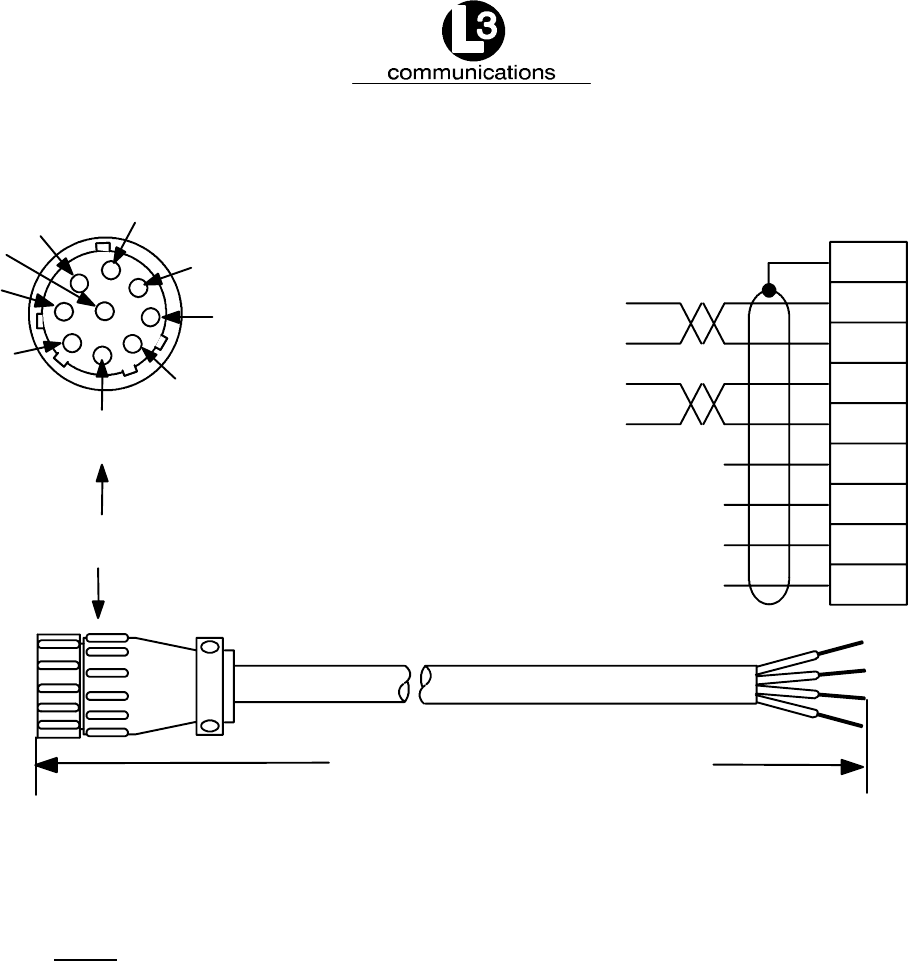
Marine Systems
Aviation Recorders
Rev. 02 Page 3--8
July 29/03
Automatic Identification System
4
2
7
9
8
6
1
3
5
Pilot Port Connector
9
2
1
7
8
5
6
3
4
Reserved Do Not Connect
WHT TXA
BLK TXB
GRN RXA
BLK RXB
SHIELD
72 in. ¦21.8 m ¦0.05 m
Reserved Do Not Connect
Reserved Do Not Connect
Reserved Do Not Connect
Figure 3--5. Pilot Port Cable
NOTE: A Digital Volt Meter may be used to determine the “A” and “B”
polarities. A negative voltage when referenced to ground would
indicate “A”, while a postive voltage when referenced to ground
would indicate “B”.

Marine Systems
Aviation Recorders
Rev. 02 Page 3--9
July 29/03
Automatic Identification System
3.1.2. Connecting the IEC Data Interface Cable
The AIS Transponder receives data from the ship’s sensors through a data interface
cable which is connected to the back of the transponder through a data port. IMO
regulations require that the ship heading, speed--over--ground (SOG), course--over--
ground (COG), rate--of--turn (ROT) and position be transmitted from the AIS. In or-
der to meet these requirements, the L--3 ProTec provides six (6) data channels to
allow the AIS to be connected to the ships Gyrocompass and DGPS system in ac-
cordance with NMEA 0183.
The L3 AIS is shipped with one IEC interface cable P/N 024--M0088--01. All IEC/Pi-
lot communications with the AIS is referenced with the L--3 ProTec considered the
“MASTER” in that transmit data is OUTPUT from the L--3 ProTec, and receive data is
INPUT to the L--3 ProTec. All channels are isolated with individual shielded twisted
pair cables. Refer to Figure 3--7. The IEC connector (J4) is located on the back of
the L--3 ProTec. (Refer to IEC 61993--2 annex D. and NMEA 0183) IEC channels 1,
2, and 3 are RECEIVE ONLY sensor inputs. Differential data (RS422) is received on
each of these channels and internally converted to TTL for input to a standard
UART. Channels 4, 5, and 8 are all RS422 interfaces. IEC channels 4 and 5 are
TRANSMIT/RECEIVE channels for AIS data. IEC channel 8 is the AIS long range
port.
3.1.2.1 Data Channels
Data enters the Transponder through six (6) available data channels. Three data
channels are low speed unidirectional (4800 baud) channels suitable for data input
to the transponder. The other three data channels are high speed bidirectional
channels (38400 baud) which support both input and output to/from the transponder.
The channels are described below by channel number and type. Suggested uses of
each channel are provided but it is not required that a user define the channels in
this fashion. The internal software in the transponder is able to distinguish the type
of data feeding from each channel provided all data streams subscribe to the IEC
61162 format (NMEA 0183).
Table 3--1. Data Channels
Channel BAUD Type Suggested Use
14800 Receive DGPS (COG, SOG, LAT, LON)
24800 Receive Rate of Turn
34800 Receive Heading (Gyro)
438400 Transmit / Receive PC Application
538400 Transmit / Receive ARPA/ECDIS
838400 Transmit / Receive Long Range Tracking (Dedicated)
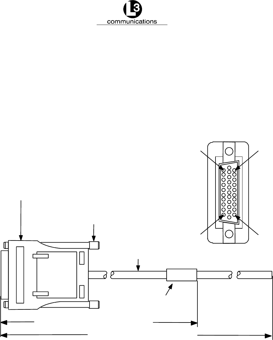
Marine Systems
Aviation Recorders
Rev. 02 Page 3--10
July 29/03
Automatic Identification System
3.1.2.2 Data Cable
Each transponder will come shipped with an 100 inches long IEC data cable (P/N
024--M0088--01) terminated at one end by a J4 connector. (Refer to Figure 3--6,
Figure 3--7 and Figure 3--8.) The IEC data cable is shielded and contains three
smaller diameter cables, each of which is also shielded. Each of these smaller
cables contains three shielded twisted pairs (STP) each and each STP includes a
drain wire. A low speed unidirectional (input only) data channel (4800 kbs) is carried
through one STP, and a high speed bidirectional (input/output) data channel (38400
kbs) will require two pairs.
P1--Connector, Cannon p/n 2PA31P
Metal or metalized plastic backshell,
Cannon p/n DA121073--150 or Equivalent
Thumbscrew, Cannon p/n 250--8501--013
or Equivalent
Cable, ECS p/n 622818
Marker, Brady p/n PWC--PK3
or Equivalent
Pin 1
Pin 10
Pin 31
Pin 22
100 in. ¦2in. 2.5 m ¦.05 m
10 in. ¦2in. 25 cm ¦5cm
Figure 3--6. AIS Transponder IEC Data Cable
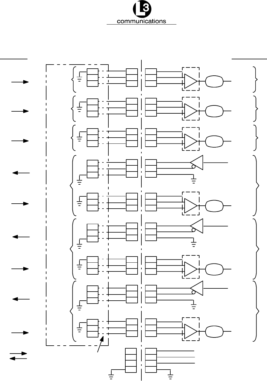
Marine Systems
Aviation Recorders
Rev. 02 Page 3--11
July 29/03
Automatic Identification System
22
1
11
DB31
22
1
11 RXD_CH1 CHANNEL 1
ISO_GND1 OPTO_ISO
B
A
23
3
13 RXD_CH2 CHANNEL 2
ISO_GND2 OPTO_ISO
B
A
24
4
14 RXD_CH3 CHANNEL 3
ISO_GND3 OPTO_ISO
B
A
25
2
12 RXD_CH4
CHANNEL 4
ISO_GND4 OPTO_ISO
B
A
8
19
29
TX_A
TX_B
CH4--TXGND
TXD_CH4
26
5
15 RXD_CH5
CHANNEL 5
ISO_GND5 OPTO_ISO
B
A
9
20
30
TX_A
TX_B
CH5--TXGND
TXD_CH5
27
6
16 RXD_CH8
CHANNEL 8
ISO_GND6 OPTO_ISO
B
A
10
21
31
TX_A
TX_B
CH8--TXGND
TXD_CH8
7
17
28
18
TEST_V+
TEST_OUT
TEST_GND
NOTES:
DATA DIRECTION IS ASSUMED WITH
THE L3 COMMUNICATIONS UAIS
REFERENCED AS THE MASTER. FOR
EXAMPLE, TRANSMIT DATA IS
TERMINATED AT THE L3 UAIS
IEC INTF MOD
7
17
28
18
N/C
N/C
N/C
23
3
13
24
4
14
25
2
12
8
19
29
26
5
15
9
20
30
27
6
16
10
21
31
J4P4
RX_A
RX_B
RX_A
RX_B
RX_A
RX_B
TX_A
TX_B
RX_A
RX_B
TX_A
TX_B
RX_A
RX_B
TX_A
TX_B
RX_A
RX_B
5
3
8
5
3
8
5
3
8
5
3
8
7
2
1
5
3
8
5
3
8
7
2
1
7
2
1
DB9 MALE
DB9 MALE
DB9 MALE
DB9 MALE
DB9 MALE
DB9 MALE
IEC CABLE OPTIONAL TERMINATION
PIGTAILS
DATA DIRECTION
CAUTION... PINOUTS
MAY VARY WITH MANUFACTURER.
RS422 TX_A AND TX_B
RS422 RX_A AND RX_B
RS422 RX_A AND RX_B
RS422 RX_A AND RX_B
RS422 TX_A AND TX_B
RS422 TX_A AND TX_B
RS422 TX_A AND TX_B
RS422 TX_A AND TX_B
RS422 TX_A AND TX_B
Figure 3--7. IEC Data Cable Interconnect Diagram
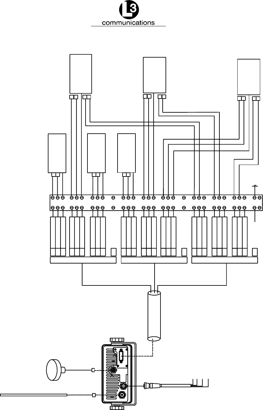
Marine Systems
Aviation Recorders
Rev. 02 Page 3--12
July 29/03
Automatic Identification System
12--24 VDC
BLACK (--)
RED (+)
GREEN (BIIT 1)
WHITE (BIIT 2)
GPS
ANT
VHF
ANT
PL 259
CONN. TNC
CONN.
RG59 COAX.
RG8X COAX.
CABLE GROUP 1
1
11
22
2
12
25
3
13
23
NC
4
14
24
5
15
26
6
16
27
NC
8
19
29
9
20
30
10
21
31
18
WHITE/BLUE
BLUE/WHITE
SHIELD
WHITE/ORANGE
ORANGE/WHITE
SHIELD
WHITE/GREEN
GREEN/WHITE
SHIELD
CABLE SHIELD
[NO CONNECT]
WHITE/BROWN
BROWN/WHITE
SHIELD
WHITE/GREY
GREY/WHITE
SHIELD
RED/BLUE
BLUE/RED
SHIELD
CABLE SHIELD
[NO CONNECT]
RED/ORANGE
ORANGE/RED
SHIELD
RED/GREEN
GREEN/RED
SHIELD
RED/BROWN
BROWN/RED
SHIELD
CABLE SHIELD
1
2
3
4
5
6
7
8
9
10
11
12
13
14
15
16
17
18
19
20
21
22
23
24
25
26
27
28
29
30
31
CABLE GROUP 2 CABLE GROUP 3
IEC DATACABLE
(31 PIN)
RATE OF TURN
NMEA 0183
RS 422 CH 2
HEADING
NMEA 0183
RS 422 CH 3
PC/EXT APP.
NMEA 0183
RS 422 CH 4
RX
TX
B
A
B
A
POSITION
NMEA 0183
RS 422 CH 1
TX
B
A
B
A
A
B
TX
B
A
B
A
RX
TX
ECDIS/ARPA
NMEA 0183
RS 422 CH 5
B
A
TX
B
A
RX
LONG RANGE
NMEA 0183
RS 422 CH 8
TX
Open = Fail
Short = Pass
Note: Akarn Relay Output
Figure 3--8. IEC Data Cable External Wiring Diagram

Marine Systems
Aviation Recorders
Rev. 02 Page 3--13
July 29/03
Automatic Identification System
3.1.2.3 Terminal Block
Each Transponder will come shipped with a 31 pin terminal block. A terminal block is
the preferred installation method for completing the data interface (NMEA) because
data output from a ship sensor ( dGPS, ROT, Gyro) may not subscribe to a standard
pinout definition. As such, each installation may require that the installer identify
and cross reference the sensor pinouts with the IEC pinouts, which is a well defined
standard pinout description. The terminal block allows for greater flexibility in com-
pleting the connection to the ship’s sensors.
A junction box may be made available which terminates the data cable on the termi-
nal block and provides serial connectors to allow for easy connection to ship sen-
sors. However, the installer will need to confirm the pinout definitions for the sensor
outputs before completing the connection correctly.
To complete the data connection to the ship’s sensors, perform the following:
(1) Connect the data cable to the back of the transponder unit.
(2) Feed the data cable into the console to the position in which the terminal block
will be placed.
(3) Locate an ideal position for the terminal block.
FProtected from weather.
FProtected from high heat.
FProtected from accidental contact with conductive material.
FWithin 100 inches (2.5 m) of the transponder due to IEC data cable length.
FGrounding of terminal block to ship’s structure.
FNeed to feed cables from navigational sensors.
(4) Mount the terminal block to the ships structure with self tapping screws
(5) Ground terminal block to ship’s structure using grounding cable provided.
(6) Connect each wire to the correct terminal block position. Use the table below
which gives the IEC pin ID (and color code) and identifies the correct terminal
block position ID.
NOTE: The metallic shielding of each of the three shielded cables
containing the twisted pairs must be connected to the ter-
minal block using the shield drain wire connected to the
shield. The shields from Cables 1 and 2 do not have to be
connected. The shield from Cable 3 must be connected to
TB pin ID 30, which is grounded to the ship’s hull.

Marine Systems
Aviation Recorders
Rev. 02 Page 3--14
July 29/03
Automatic Identification System
NOTE: Each shielded twisted pair of wires is shielded as well by
metallic shielding and a drain wire connected to this shield-
ing is to be connected in accordance with Table 3--2.
Table 3--2. IEC Cable and Junction Box Pinouts
Cable STP Wire Color IEC Pin TB Pin
1White / Blue 1 1
Blue / White 11 2
Drain 22 3
2White / Orange 2 4
Cable 1 Orange / White 12 5
Drain 25 6
3White / Green 3 7
Green / White 13 8
Drain 23 9
Shield Drain NC 10
4White / Brown 411
Brown / White 14 12
Drain 24 13
5White / Gray 514
Cable 2 Gray / White 15 15
Drain 26 16
6Red / Blue 617
Blue / Red 16 18
Drain 27 19
Shield Drain NC 20
7Red / Orange 821
Orange / Red 19 22
Drain 29 23
8Red / Green 924
Cable 3 Green / Red 20 25
Drain 30 26
9Red / Brown 10 27
Brown / Red 21 28
Drain 31 29
Shield Drain 18 30

Marine Systems
Aviation Recorders
Rev. 02 Page 3--15
July 29/03
Automatic Identification System
3.1.3. Installing the VHF Antenna
Installation of a VHF antenna is as important to reliable communications as the
transceiver itself. It is recommended that a high quality antenna be purchased from
an established source and that all manufactures instructions be followed with partic-
ular attention to cable routing and connector installation. Some important consider-
ations in antenna installation are:
FIn general, antennas should be located as high as practical on the vessel
and separated as much as possible from each other.
FThe VHF antenna should be placed in an elevated position with a mini-
mum of 2 meters clearance from any construction that is made with con-
ductive material. In addition, it should not be installed close to any large
vertical obstruction, and the VHF antenna should have a 360°line of sight
to the horizon.
FIt is preferable that the VHF antenna is installed at least 3 meters away
from high power energy sources such as radar and other transmitting ra-
dio antennas, and out of the transmitting beam.
FThere should not be more than one antenna on the same level. The AIS
VHF antenna should be mounted directly above or below the ship’s prima-
ry VHF radiotelephone antenna, with no separation and with a minimum of
2 meters vertical separation. If the VHF antenna is located on the same
level as other antennas, the distance between them should be at least 10
meters.
To install the VHF antenna, perform the following:
(Refer to Figure 3--9 and Figure 3--10.)
(1) Position the antenna mounting bracket on a rigid and structurally sound sur-
face. In general, two bracket types are available, a rail mount and a flat (pad-
eye) mount. Some mounts have a ratchet mechanism which allows them to be
mounted on an inclined surface. Whichever mount is used; ensure the quality
of the mount. L--3 recommends a heavy gage stainless steel mount be used in
the mounting of the antenna.
(2) Install the antenna on the antenna mount.
(3) Run the coaxial cable from the antenna to the transponder location. Use only
high quality RG8X or RG214 coaxial cable and keep cable length as short as
possible to reduce signal attenuation.
(4) Trim cable to length leaving a few inches slack at the transponder.
(5) Attach the connectors to the end of the coaxial cable.
(6) Connect the cables to the transponder. Soldering the connection is not
required.

Marine Systems
Aviation Recorders
Rev. 02 Page 3--16
July 29/03
Automatic Identification System
3.1.4. Installing the GPS Antenna
The correct installation of a GPS antenna is crucial to the operation of the trans-
ponder because the internal transmission synchronization relies on the accuracy of
the time signal obtained from the GPS. It is recommended that a high quality GPS
antenna be purchased from an established source and that all manufactures instruc-
tions be followed with particular attention to cable routing and connector installation.
Some important considerations in GPS antenna installation are:
FGPS antennas should be located to provide a clear, unobstructed view of
the sky.
FGPS signals can be affected by RADAR and SATCOM transmissions. As
such, GPS antennas should be positioned below and at least 5 meters
away from RADAR and SATCOM antennas and outside of the beam path.
FGPS signals can also be affected negatively by VHF and HF transmis-
sions, and the GPS antenna should be positioned at least 3 meters from
these types of antennas.
FThe GPS antennas can be flat mounted onto any surface but it is recom-
mended that it be elevated from the deck surface (20--30 cm) to prevent
ice or spray from negatively impacting the signal reception.
FRecently, it has been identified that certain makes/models of TV antennas
can drastically interfere with GPS reception. As such, the installer should
place the GPS antenna as far away from any shipboard TV antennas as
possible and confirm that any antennas used on board are not ones which
have been exhibited GPS interference problems.
To install the GPS antenna, perform the following:
(Refer to Figure 3--9 and Figure 3--10.)
(1) Position the antenna mounting bracket and/or antenna mast on a rigid and
structurally sound surface.
(2) Install the antenna on the antenna mount.
(3) Run the coaxial cable from the antenna to the transponder location through an
existing throughhull. Use only high quality RG59 coaxial cable and keep cable
length as short as possible to reduce signal attenuation.
(4) Trim cable to length leaving a few inches slack at the transponder.
(5) Attach the connectors to the end of the coaxial cable.
(6) Connect the cable to the transponder. Soldering the connection is not required.
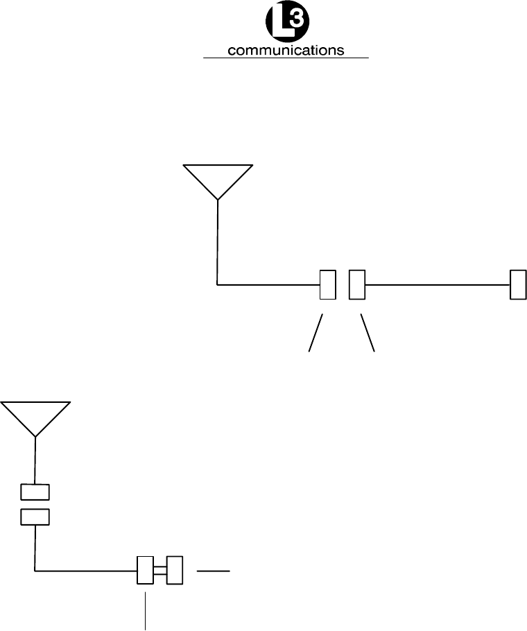
Marine Systems
Aviation Recorders
Rev. 02 Page 3--17
July 29/03
Automatic Identification System
Mini VHF Connector
VHF Antenna
Female Male
PL259
50 ft.
RG8X
20 ft.
GPS Antenna
TNC Connector Male
TNC Connector Female
70 ft.
RJ223
15 m
21 m
6m
Figure 3--9. AIS Transponder Antenna Diagram
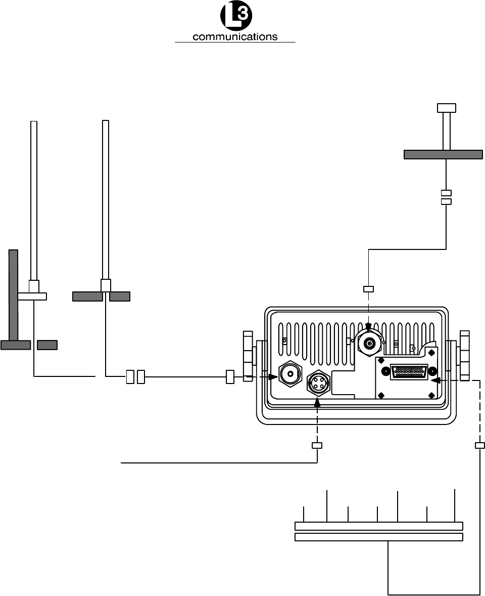
Marine Systems
Aviation Recorders
Rev. 02 Page 3--18
July 29/03
Automatic Identification System
Back Panel Mating Connectors
VHF Antenna -- L3 PN: PL--259 (Generic) (20 ft. cable supplied)
TELEGARTNER J01041A0004
Power BIIT -- L2 PN: 063--98--02108 (6 ft. cable supplied)
CONXALL PN: 6382--4SG--522
GPS -- L3 PN: TNC (Generic) (20 ft. cable supplied)
IEC NMEA -- L3 PN: 063--98--02106 (100 in. cable supplied)
HIROSE PN: HR22--12TPD--20S
Power Consumption:10--32vdc
12 watts nominal -- 50 watts max.
OTHER
PILOT/PC
ECS
ARPAROT
COG
DGPS
TERMINAL BLOCK
IEC/NMEA DATA
TNC CONN
70’ RG59 COAX
TNC CONN
MALE
MALE 50’ RG8X COAX
20’ RG8X COAX
Mini VHF CONN PL 259
NOTES:
GPS ANTENNA
RAIL MOUNTED DECK MOUNTED
VHF ANTENNA
21 m
15 m
6m
Figure 3--10. AIS Transponder Rear View
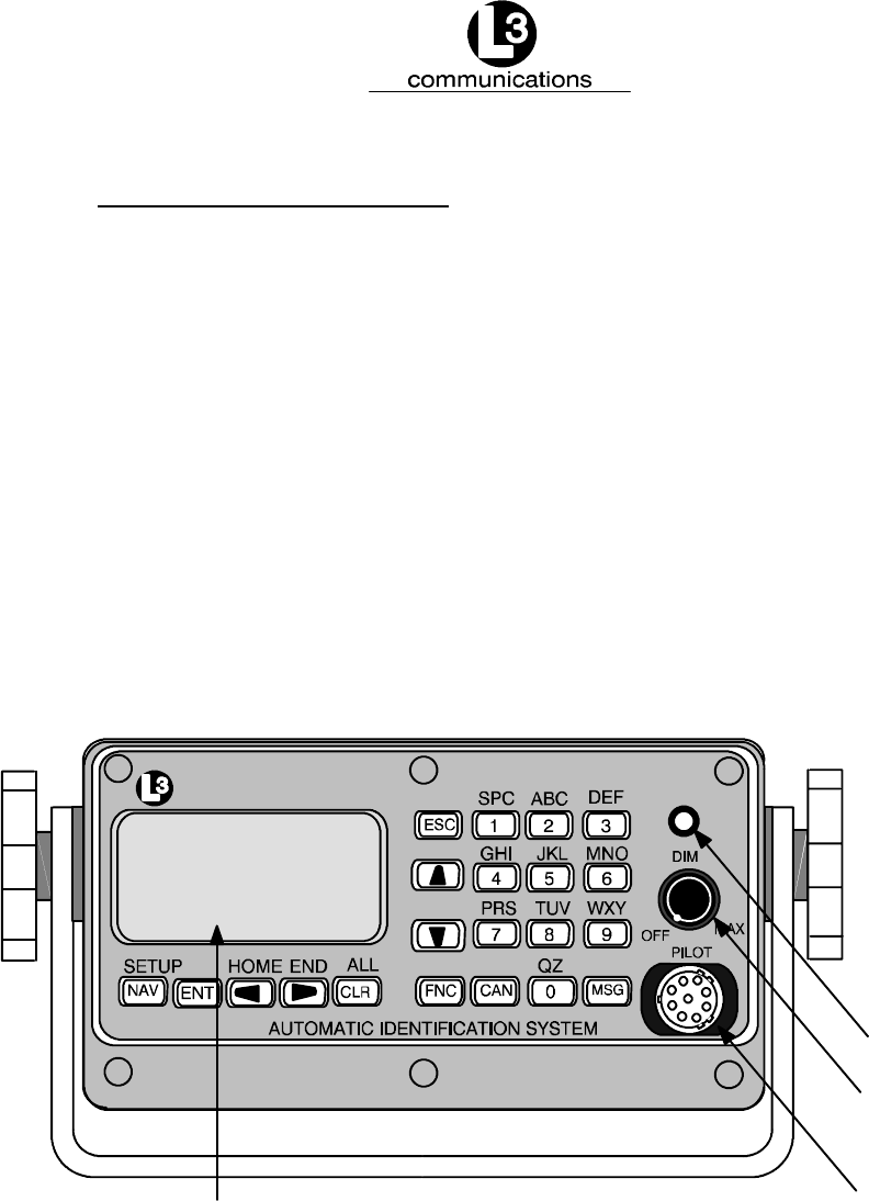
Marine Systems
Aviation Recorders
Rev. 02 Page 3--19
July 29/03
Automatic Identification System
3.1.5. PowerUp and Configuration
At this stage you should have the following steps completed:
FTransponder installed and 10--32 Vdc power connected.
FVHF antenna installed and connected to transponder.
FGPS antenna installed and connected to transponder.
FIEC data cable installed and connected to transponder and terminal block.
The next step in the installation of the AIS transponder involves setup and configura-
tion. A complete description of the interface and menu system is previously given in
Section 2. Figure 3--11 presents a view of the layout of the integral Minimum Key-
board Display. This display includes a backlit LCD screen and keypad which allows
the user to enter the required static and voyage related vessel data. A complete de-
scription of the user interface and menu system is presented in Section 2. The con-
figuration process is summarized below. The following procedure should be followed
to carry out final setup and testing of the AIS Transponder.
communications
Power/Dim
Status Light
Pilot Port
Display Window
Figure 3--11. AIS Transponder MKD
(1) Turn on the Transponder. Rotate the POWER button clockwise. This knob
also controls the brightness of the backlighting such that rotation of the knob
clockwise dims the backlight level.
(2) Check the STATUS light to ensure power is supplied to unit. Steady light indi-
cates normal operation.

Marine Systems
Aviation Recorders
Rev. 02 Page 3--20
July 29/03
Automatic Identification System
(3) Enter Vessel Static Information and Voyage Information. Press FNC and then
NAV to get to the System Configuration screen.
Sy s t
Lo
Ve
An
Vi
Vi
Vi
Ed
em
go
C
ff
ss
te
el
nn
ew
ew
S
A
ew
it
D
C
onf i
/V
a
oy
Po
af
la
et
rm
ow
ha
n--
n
g
a
s
y
T
M
and
ge
it
S
io
T
St
ex
at
im
gm
e
t
St a
et
n
up
Se
t
us
Lo
Lo
Se
g
tt
tus
tup
g
i ngs
Figure 3--12. System Configuration Screen
(4) Use DOWN ARROW key to scroll down to Vessel Data Setup. Click ENT.
(5) This will bring you to a screen which allows you to enter the vessel’s data. The
destination and ETA fields may be entered once the ship deploys. The layout of
the screen is shown below.
V
MM
IM
SI
O#
CS
Na
gn
me
De
ET
st
A
esse
:0
:0
00
:S
:L
QA
3
:S
:M
AR
MD
l/Vo
0000
EXAM
AS
D®
OT
00
y
0
P
A
--
age
0Na
Ma
LE
Ty
00 H
Set u
vS
xD
:U
:0
pe: 0
HMM®
p
ND
.0
FN
00: 0
D
0
Figure 3--13. Vessel Data Setup
The fields are described as follows:
MMSI: Maritime Mobile Service ID (Maximum 9 characters)
NavS: Navigational Status. When in field, use down arrows to scroll through
available option and click ENT to select.
IMD#: Official IMO designation ID for vessel
(0 = not available= default)
MaxD: Maximum sailing draft in Meters
(0.1 to 25.5 meters)

Marine Systems
Aviation Recorders
Rev. 02 Page 3--21
July 29/03
Automatic Identification System
Csgn: Radio Callsign
(maximum 7 characters)
Type: Vessel Type
(see codes listed in Table 3--3 below)
Name: Vessel Name
(maximum 20 characters)
Dest: Name of next Destination
(maximum 20 characters)
ETA: Estimated Time of Arrival
(MMDDHHMM UTC)
Table 3--3. Vessel Type Codes
Special Crafts Other Ships
First Digit Second Digit
50 Pilot Boats
51 Search and Rescue Vessels
52 Tugs
53 Port Tenders
54 Vessels with anti--pollution
facilities or equipment
55 Law Enforcement Vessel
56 Spare -- for assignment to
local vessels
57 Spare -- for assignment to
local vessels
58 Medical Transport
59 Spare -- for assignment to
other special vessels
6 Passenger Ships
7 Cargo Ships
8 Tankers
9 Other types of
ships
DG: Dangerous
Goods
HS: Harmful
Substances
MP: Marine Pollunants
0 All ships of this type
1 Carrying DG HS or MP
IMO hazard or polluant
category A
2 Carrying DG HS or MP
IMO hazard or polluant
category B
3 Carrying DG HS or MP
IMO hazard or polluant
category C
4 Carrying DG HS or MP
IMO hazard or polluant
category D
5 Not under command
6 Restricted by her ability
to manuever
7 Constrained by her
draught
8 Spare
9 No additional information

Marine Systems
Aviation Recorders
Rev. 02 Page 3--22
July 29/03
Automatic Identification System
The following keyboard commands will allow you to navigate and complete the data
entry requirements for this screen.
FUse the LEFT, RIGHT, UP, DOWN arrows to navigate between fields.
FUse the ENT key to select a field to enter.
FUse the alphanumeric keypad to enter the required data into the field.
FUse ENT to save the data entered into the field.
FUse CAN to cancel any changes made to a field
(6) After entering the required data, Click ENT and ENT again to return to System
Configuration.
(7) Use DOWN ARROW key to scroll down to Antenna Position. Click ENT to se-
lect.
(8) In this screen you will be asked to enter the relative position of the location of
the antennas for both the ship’s (external) dGPS systems and the AIS’ (inter-
nal) GPS system.
A
IN
EX
T
T
D
S
im
ee
nt en
A:
A:
0
0
en
I
si
TU
na P
B:
B:
on
-- R
s
M
o
0
0
i
.
si t i
C
C
n
13
Me
71
on R
:0
:0
te
D
rs
oc
ef
D:
D:
0
0
Figure 3--14. Antenna Position
The INT antenna is the antenna dedicated to the GPS receiver internal to the AIS.
The EXT antenna is the antenna dedicated to the ship’s dGPS. The dimensions are
to be entered in Meters and are defined as follows: (Refer to Figure 3--15.)
A Distance in meters from Forward Perpendicular (FP)
B Distance in meters from After Perpendicular (AP)
C Distance in meters inboard from port side
D Distance in meters inboard from starboard side
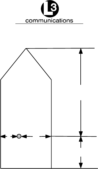
Marine Systems
Aviation Recorders
Rev. 02 Page 3--23
July 29/03
Automatic Identification System
A
B
CD
Figure 3--15. Calculating Antenna Position
(9) This completes the configuration requirements of the AIS. The next step involves
checking the system linkup to ship’s dGPS and Gyro. To check these links you
must enter the Own Ship Data screen of the interface.
(10) Enter FNC and then ENT. This will get you to Own Ship Data screen. The screen
will display ship positional and heading information.
(11) Confirm ship positional data, heading and SOG/COG/ROT data is correct by refer-
encing the equipment repeater display.
The AIS is now placed in service. It is to remain operational at all times when the
vessel is operating unless given specific authorization to discontinue operation by
local maritime authorities. The only interaction with the interface will be to view sur-
rounding ship traffic identification information and to enter voyage specific data at
the start of each voyage.
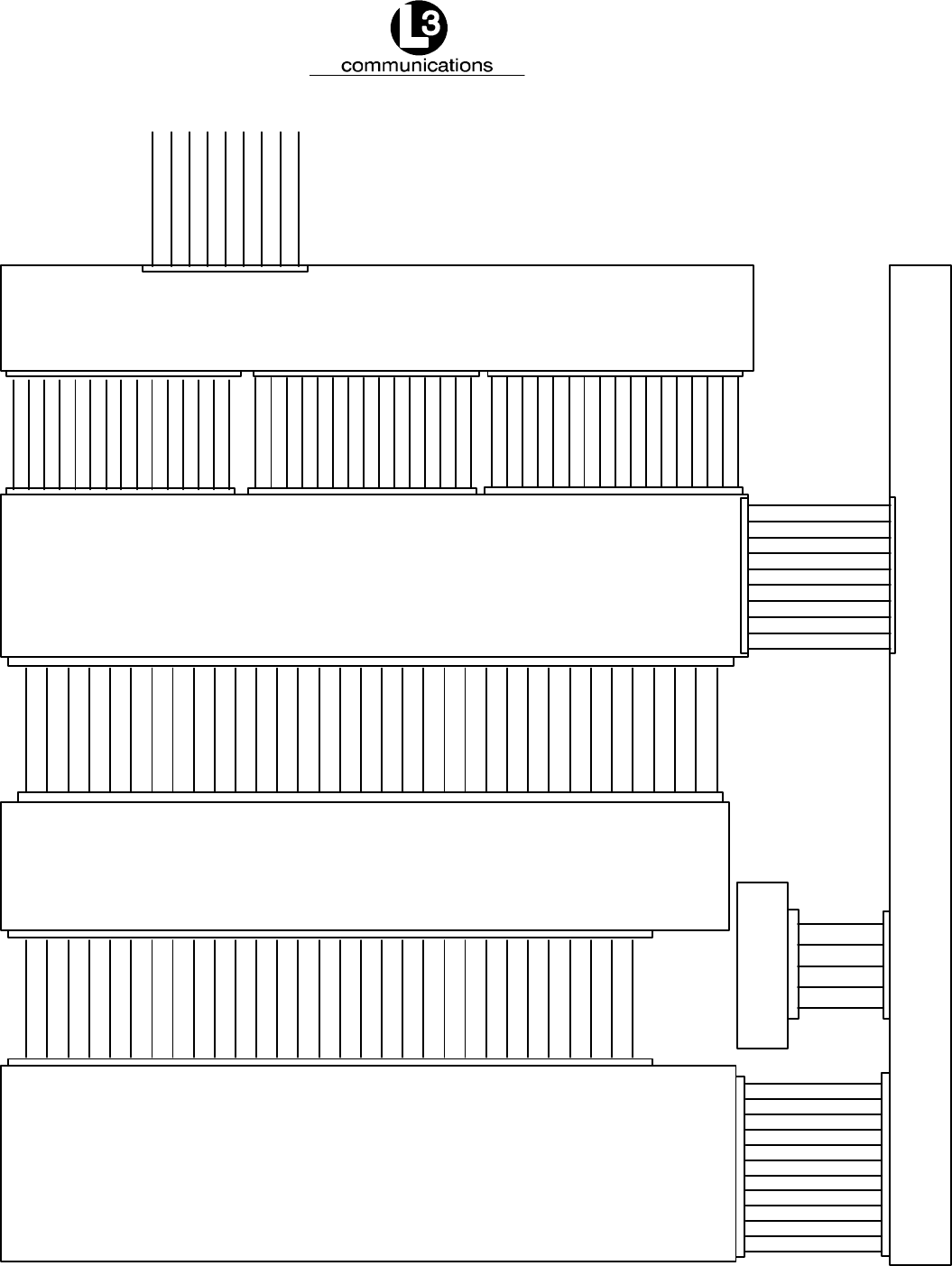
Marine Systems
Aviation Recorders
Rev. 02 Page 3--24
July 29/03
Automatic Identification System
1
2
3
4
5
6
7
8
9
10
11
12
13
14
15
16
17
18
19
20
21
22
23
24
25
26
27
28
29
30
1
2
3
4
5
6
7
8
9
10
11
12
13
14
15
16
17
18
19
20
21
22
23
24
25
26
27
28
29
30
31
32
33
34
1
2
3
4
5
6
7
8
9
10
11
12
+12 volts
+12 volts
ON_OFF1
BIIT_CONT
On_Off2
+5 volts
GPSRXD
+8 volts
GPSTXD
GPSEL
GND
GND
GND
+8 volts
3GMSK_MOD
VCC
LOC/DIS
GMSK1IN
RX2LOCK
SMTR1
RX1_LOCK
SYNKCLK
SYNDAT
SMTR2
VREF+
HI/LO
TX_CMD
GMSK2IN
BIIT_CONT
SQ_BRK_ANT
SYN_RX_IN
SYN_RX2EN
SYN_TXEN
ON_OFF1
ON_OFF2
+12 volts
GPS_TXD
BW_CONT
TX1_LOCK
GPS_RXD
GPSSEL
UAIS RF MAIN UAIS
205M0003---01
BOARD
UAIS COMPUTER
205M0005---02
BOARD
UAIS CONTROLLER BOARD
205M0008---00
GPSTXD
NMEA_IN
GND
+8 volts
TX_MOD
VCC
LOC/DIS
RCVR1_AUD
RX2_LOCK
SMTR1
RX1_LOCK
SYN_CLK
SYN_DAT
SMTR2
VREF+
HI/LO
TXCMD
RCVR70_AUD
BIIT_CONT
SQ_BRK_ANT
SYN_RX1_EN
SYN_RX2_EN
SYN_TX_EN
ON/OFF1
ON/OFF2
+12 volts
RCVR2_AUD
70DAT
GPS_RXD
BW_CONT
RELAY_CONT
NMEA_OUT
TX1_LOCK
1
2
3
4
5
6
7
8
9
10
11
12
13
14
15
1
2
3
4
5
6
7
8
9
10
11
12
13
14
15
1
2
3
4
5
6
7
8
9
10
11
12
13
14
15
16
17
VIEW
RESET
AD0
LCD_EN
RD
WR
D0
D1
D7
D2
D3
D4
D5
D6
+8 volts
PILOT_RXA
PILOT_RXB
PILOT_TXB
ROW1_IN
ROW2_IN
ON/OFF2
ROW0_IN
PILOT_TXA
GND
+12 volts
COL_1
COL_0
COL_2
ON/OFF1
RCVR_TEST
GND
VREFB
VCC
GPS_TXD
UAIS
205M0051---00
BOARD
1
2
3
4
5
6
7
8
9
10
BIT_LED_RD
THERMAL_FAULT
BIT_LED_GN
SP1TX_OUT
GND
GPS_RXD
GPS_TXD
SP1RX_IN
GPS_SEL
SP1_1PPS
1
2
3
4
5
6
7
8
9
PILOT_TXA
GND
+8 volts
PILOT_TXB
PILOT_RXA
PILOT_RXB
TRACE_MANAGER
RCVR_SINAD
CHASSIS_GND
1
2
3
4
5
CLK_SP1
TXD_SP1
RXD_SP1
+5 volts
GND
IEC BOARD
205M0274---00
J1
J6
J2 J613
J605
J603
J703 J702
J1
J604
J602
J1
J3
J2
PILOT
PORT
(E11)
J2 J7
BOARD
205M0023---00
CHANNEL 70 DISPLAY