L3 Technologies AISA3 Protec Mobile AIS Transceiver AISA3-000-XX User Manual title
L-3 Communications Protec Mobile AIS Transceiver AISA3-000-XX title
UserManual.wiki
>
L3 Technologies
>
AISA3 User Manual
Manual
Navigation menu
Upload a User Manual
Namespaces
Wiki Guide
HTML
PDF
Info
Views
User Manual
Discussion / Help
Navigation


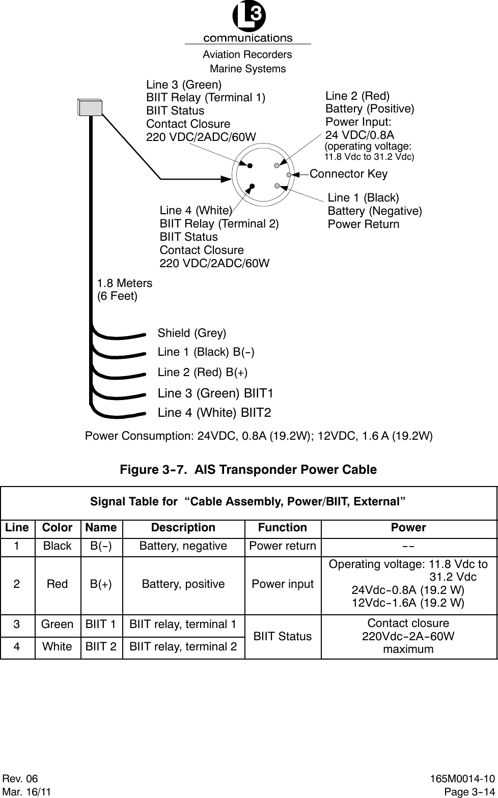
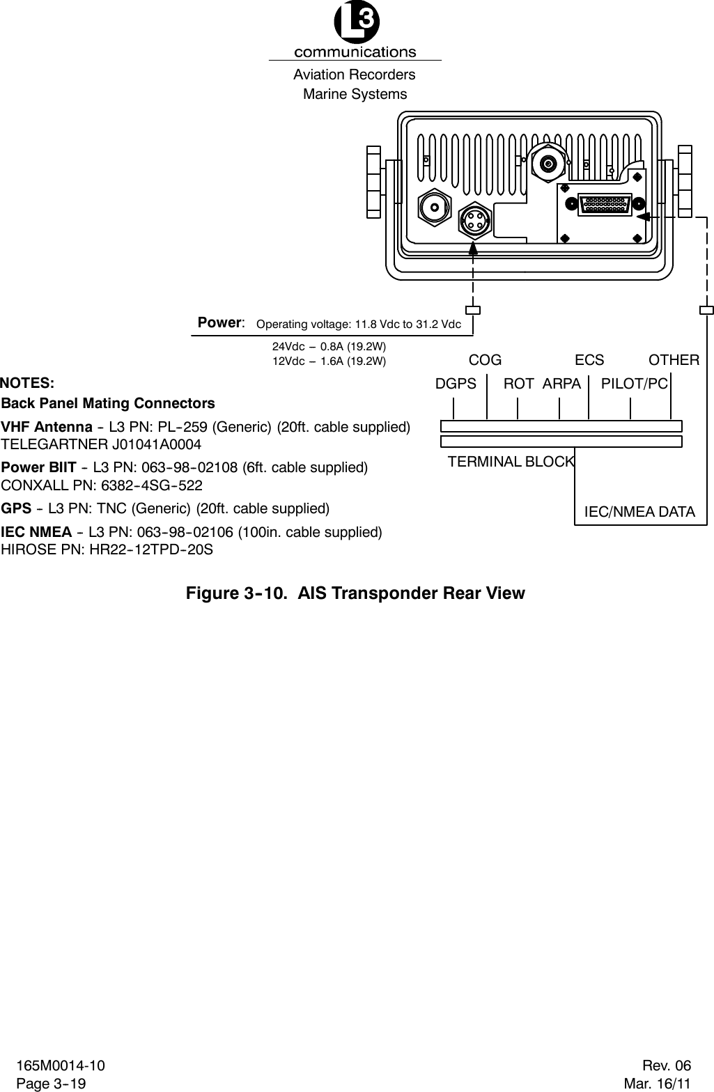
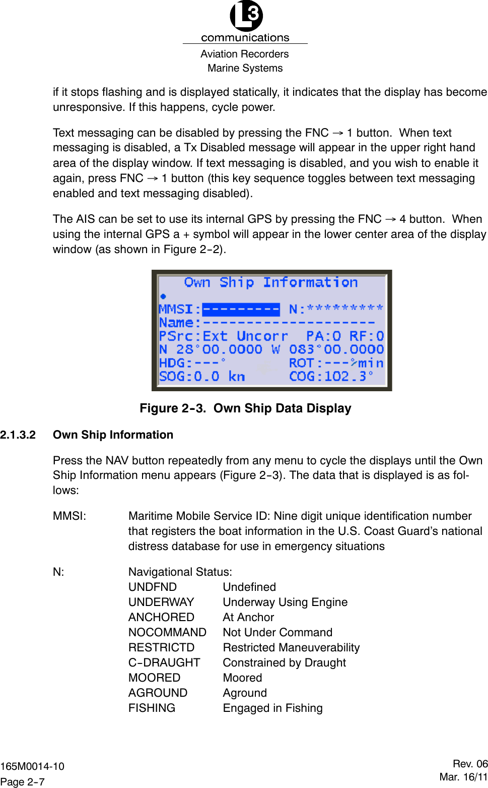
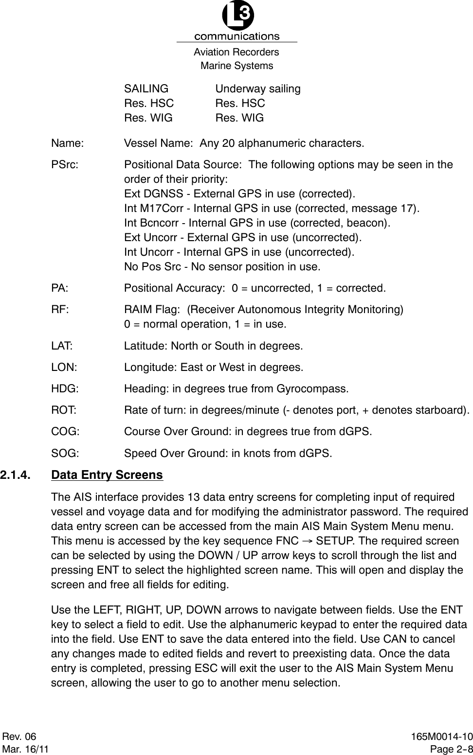
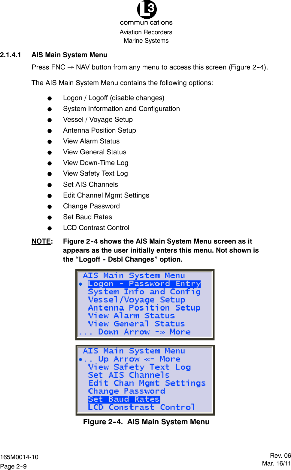
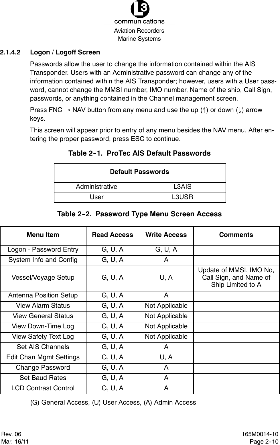
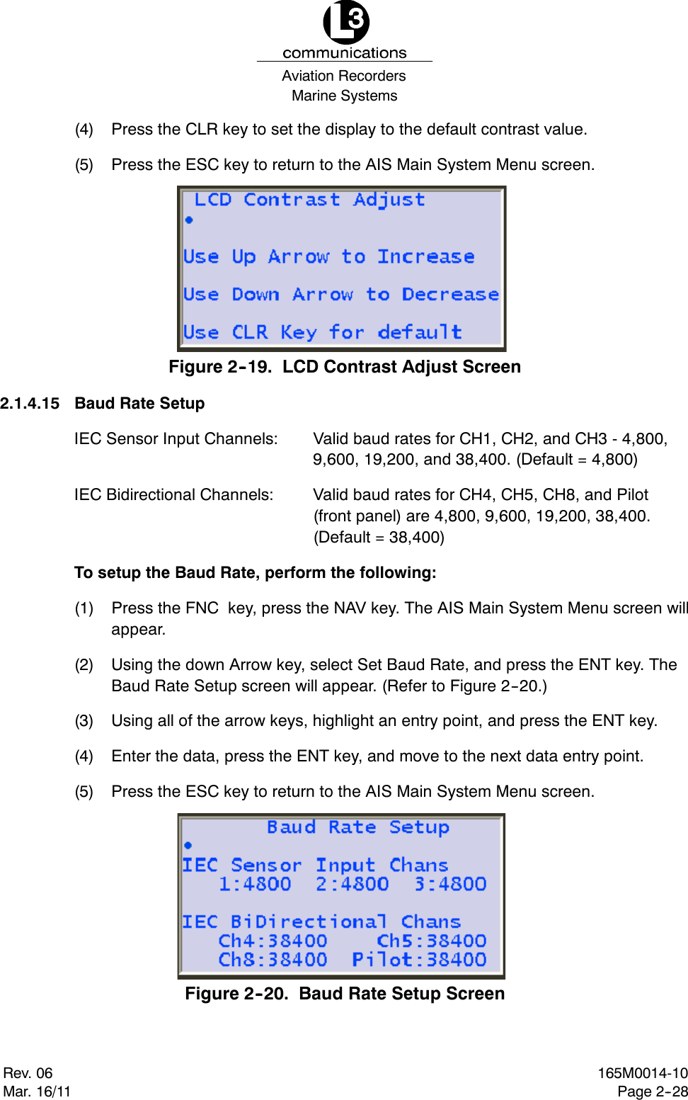
![Marine SystemsAviation RecordersRev. 06Mar. 16/11165M0014-10Page 1--7Internal GPS Receiver12 Channel, UTC Synchronization Jitter: 100ms[Time between slot start and transmitter on.]Navigational dataCOG/SOG, ROT, POS, Heading from external sourcesDisplayIntegral MKD with 160 x 64 Dots backlit LCDINTERFACEInput ABM,ACA,ACK,AIR,BBM,DTM,GBS,GGA,GLL,GNS,HDT,OSD, SSD, RMC, ROT, VBW, VSD, VTGOutput ABK, VDO, VDM, ACA, ACS, ALR, LRF, LR1, LR2, LR3, TXTPower Supply24Vdc nominal, complies with IEC 60945. Operating voltage: 11.8Vdc to 31.2Vdc.Power consumption: 24Vdc -- 0.8A (19.2W); 12Vdc -- 1.6A (19.2W).EnvironmentIEC 60945 Ed. 4 for Protected EnvironmentFrequencyVHF Marine Band](https://usermanual.wiki/L3-Technologies/AISA3/User-Guide-1434626-Page-13.png)
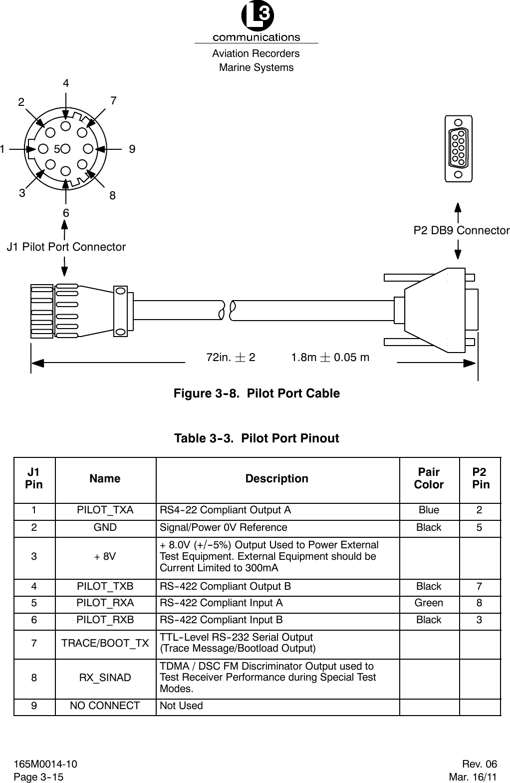
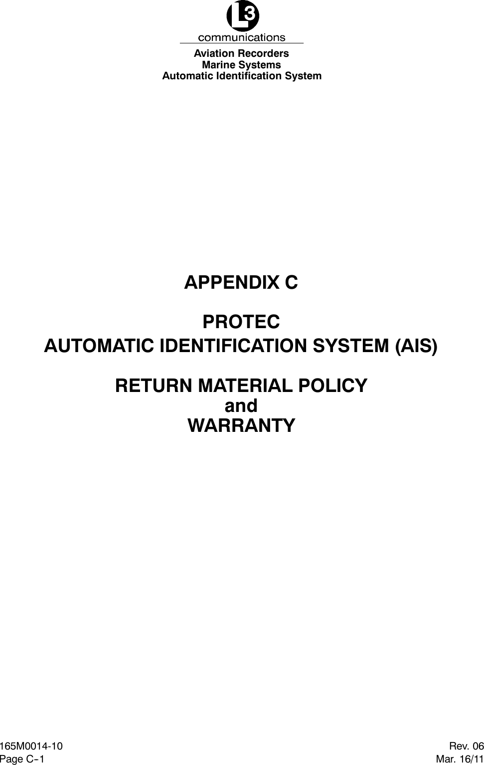
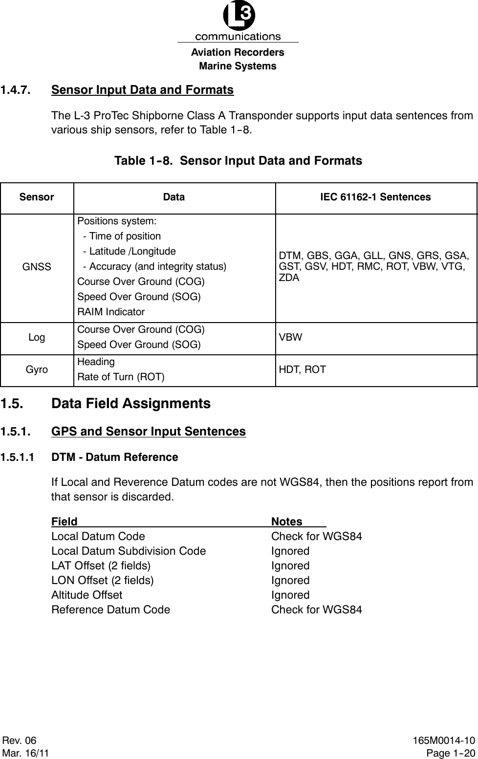
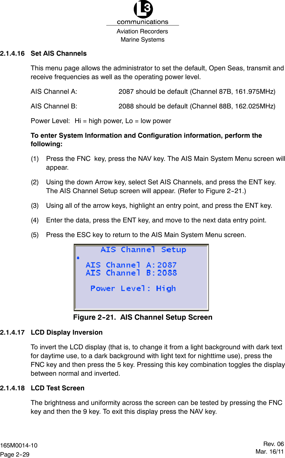
![Marine SystemsAviation RecordersRev. 06Mar. 16/11165M0014-10Page 1--13FDimensions of ship - to nearest meter.FLocation on ship where reference point for position reports is located.FType of position fixing device - various options from differential GPS to un-defined.FDraught of ship - 1/10 to 25.5m [note “air-draught” is not provided].FDestination - 20 alphanumeric characters are provided.1.3.9. AIS FrequenciesThe International Telecommunications Union World Radio Conference in 1997 desig-nated two VHF radio frequencies: 161.975MHz (AIS1, or channel 87B) and162.025MHz (AIS2, or channel 88B) for AIS. In the US, the first channel is owned byMariTEL, a public coast station operator, and the second by the federalgovernment. The USCG signed a Memorandum of Agreement with MariTEL for useof AIS 1, and has authority from the National Telecommunications and InformationAdministration to use both AIS1 and AIS 2 US-wide for AIS operation. The USCGhas asked the Federal Communications Commission to authorize any US vessel tooperate AIS on these two channels under its existing ship station license. The FCCreleased a Notice authorizing operation of AIS under a ship’s existing station license.1.3.10. AIS Input SentencesThis section lists the input sentences received by the L-3 ProTec AIS Transponder.The input sentences are categorized as Pilot, Long Range, and Sensor, which arelisted as follows:PilotABM, BBM, AIR, VSD, SSD, ACK, ACA, AIQLong RangeLRI, LRFSensorRMC, VTG, ROT, HDT, GNS, GLL, GGA, GRS, GSA, GST, GSV, ZDA, GBS, DTM,VBW](https://usermanual.wiki/L3-Technologies/AISA3/User-Guide-1434626-Page-19.png)
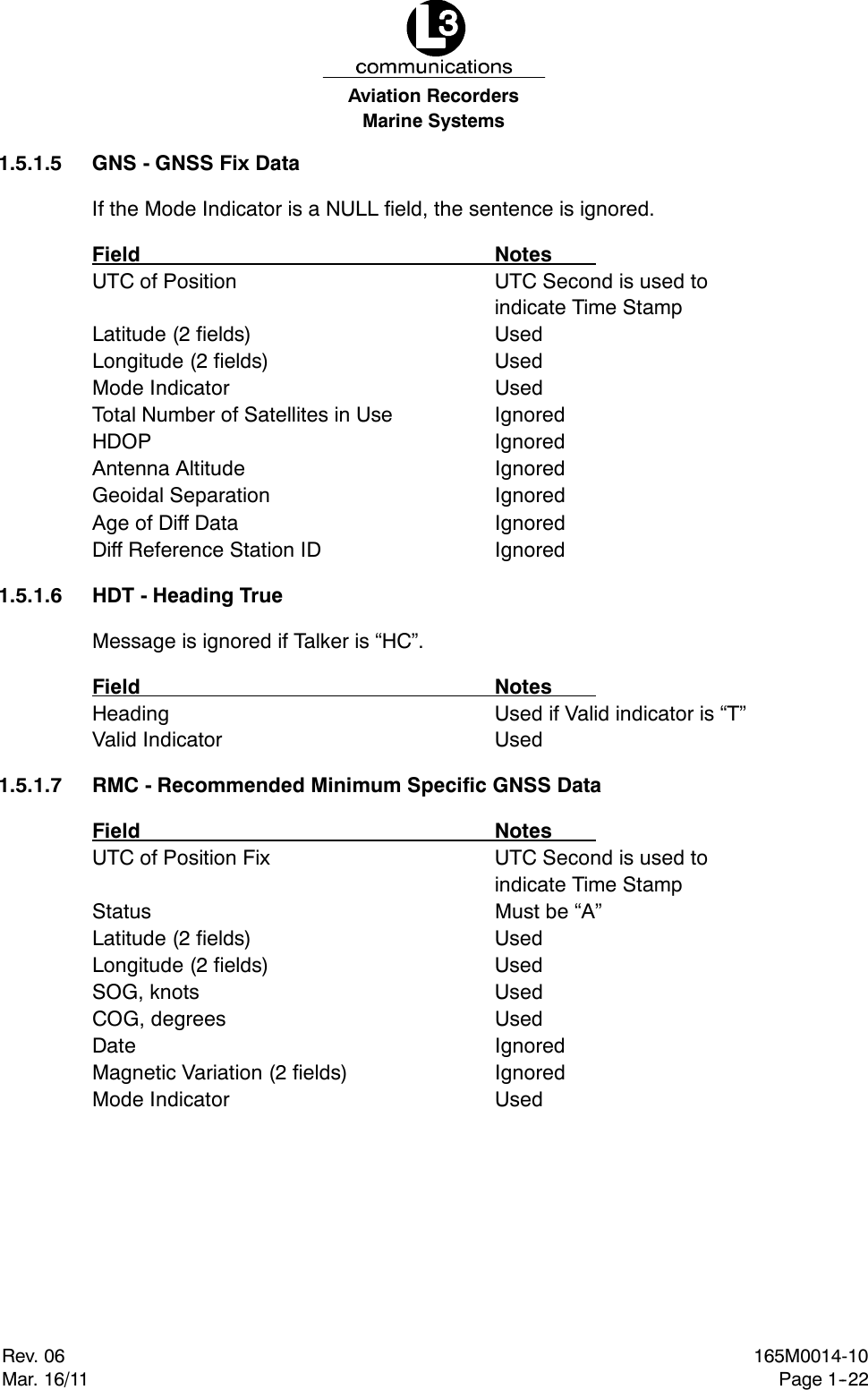


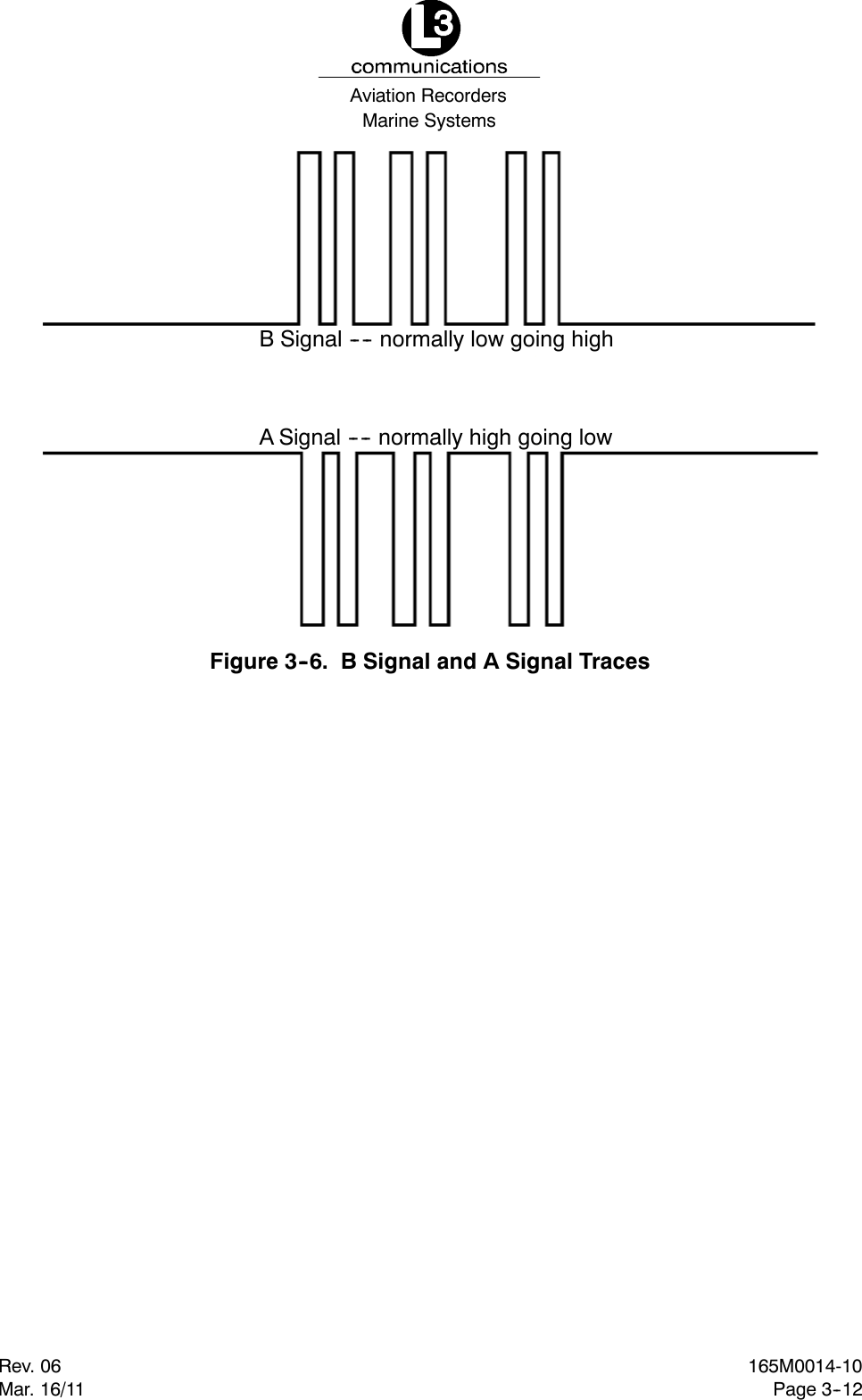
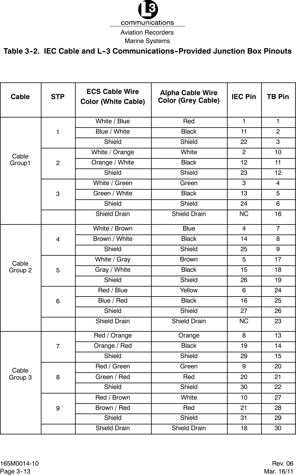
![Marine SystemsAviation RecordersRev. 06Mar. 16/11165M0014-10Page 3--10BLACK (--)RED (+)GREEN (BIIT 1)WHITE (BIIT 2)GPSANTVHFANTPL 259CONN.TNCCONN.CABLE GROUP 1111222122531323NC414245152661627NC819299203010213118CABLE GROUP 2 CABLE GROUP 3IEC DATA CABLE(31 PIN)RATE OF TURNNMEA 0183RS 422 CH 2HEADINGNMEA 0183RS 422 CH 3PC/EXT APP.NMEA 0183RS 422 CH 4TXTXBABAPOSITIONNMEA 0183RS 422 CH 1TXBABAABTXBABATXRXECDIS/ARPANMEA 0183RS 422 CH 5BARXBATXLONG RANGENMEA 0183RS 422 CH 8RXOpen = PassShort = FailNote: Alarm Relay OutputJUNCTION BOXTERMINAL BLOCKREDBLACKSHIELDWHITEBLACKSHIELDGREENBLACKSHIELDCABLE SHIELD[NO CONNECT]BLUEBLACKSHIELDBROWNBLACKSHIELDYELLOWBLACKSHIELDCABLE SHIELD[NO CONNECT]ORANGEBLACKSHIELDGREENREDSHIELDWHITEREDSHIELDCABLE SHIELDSee Figure 3--5 for A Signal and B Signal tracesNOTE: Each shielded twisted pair of wires is shielded as well by metallic shielding, and a drain wire connected tothis shielding is to be connected in accordance with Table 3--2.NOTE: A=(+) Positive, B=(--) Negative.RxARxARxARxARxARxATxATxATxARxBTxBRxBRxBRxBRxBRxBTxBTxBFigure 3--4. IEC Data Cable (Alpha Cable (Grey Covering)) External WiringDiagram with L--3 Communications--provided Junction Box](https://usermanual.wiki/L3-Technologies/AISA3/User-Guide-1434626-Page-74.png)
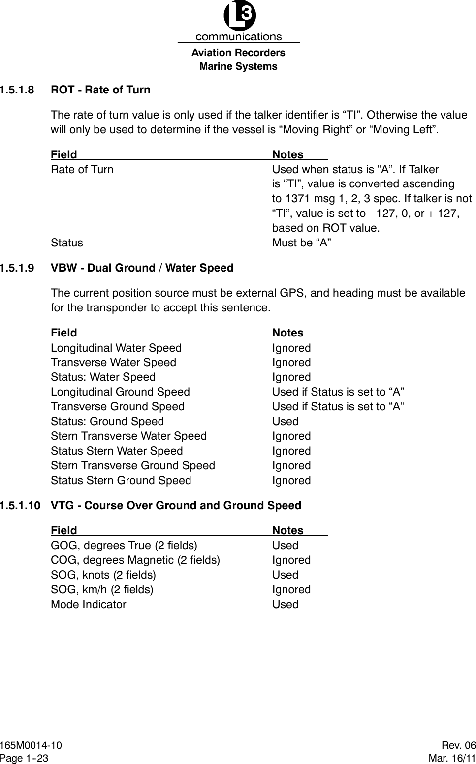
![Marine SystemsAviation RecordersRev. 06Mar. 16/11165M0014-10Page 3--11BLACK (--)RED (+)GREEN (BIIT 1)WHITE (BIIT 2)GPSANTVHFANTPL 259CONN.TNCCONN.CABLE GROUP 1111222122531323NC414245152661627NC819299203010213118CABLE GROUP 2 CABLE GROUP 3IEC DATA CABLE(31 PIN)RATE OF TURNNMEA 0183RS 422 CH 2HEADINGNMEA 0183RS 422 CH 3PC/EXT APP.NMEA 0183RS 422 CH 4TXTXBABAPOSITIONNMEA 0183RS 422 CH 1TXBABAABTXBABATXRXECDIS/ARPANMEA 0183RS 422 CH 5BARXBATXLONG RANGENMEA 0183RS 422 CH 8RXOpen = PassShort = FailNote: Alarm Relay OutputJUNCTION BOXTERMINAL BLOCKWHT/BLUBLU/WHTSHIELDWHT/ORGORG/WHTSHIELDWHT/GRNGRN/WHTSHIELDCABLE SHIELD[NO CONNECT]WHT/BRNBRN/WHTSHIELDWHT/GRYGRY/WHTSHIELDRED/BLUBLU/REDSHIELDCABLE SHIELD[NO CONNECT]RED/ORGORG/REDSHIELDRED/GRNGRN/REDSHIELDRED/BRNBRN/REDSHIELDCABLE SHIELDSee Figure 3--5 for A Signal and B Signal tracesNOTE: Each shielded twisted pair of wires is shielded as well by metallic shielding, and a drain wire connected tothis shielding is to be connected in accordance with Table 3--2.NOTE: A=(+) Positive, B=(--) Negative.RxARxARxARxARxARxATxATxATxARxBTxBRxBRxBRxBRxBRxBTxBTxBFigure 3--5. IEC Data Cable (ECS Cable (White Covering)) External WiringDiagram with L--3 Communications--provided Junction Box](https://usermanual.wiki/L3-Technologies/AISA3/User-Guide-1434626-Page-75.png)