LAMAR (CHAMPION) Elliptical Manual L0601160
C44F C44F LAMAR ELLIPTICAL - Manuals and Guides L0601160 View the owners manual for your LAMAR ELLIPTICAL #C44F. Home:LAMAR:/ Elliptical Machine Parts:LAMAR elliptical machine parts:#C44F LAMAR elliptical machine parts:#C44F LAMAR elliptical manual
User Manual: LAMAR LAMAR (CHAMPION) Elliptical Manual LAMAR (CHAMPION) Elliptical Owner's Manual, LAMAR (CHAMPION) Elliptical installation guides
Open the PDF directly: View PDF ![]() .
.
Page Count: 24

( hampion and ( logo are used raider license fi'om Champion Atldeficwear
ASSEMBLY INSTRU IONS /OI ERS MANUAL
IMPORTANT:
S._rET'£ :
SERIAL NO.
Part No. 06055
READ ALL ASSEMBLY ENSTRUCTIONS .kND SAFETY PRE(A[THONS BEFORE USLNG THIS PRODUCT. REFERENCE ALL
SAFETY GUIDELLNES AND X__Aa_NINGLABELS. RETALN PRODUCT LITERAT[_E FOR FI_RE REFERENCE.
PROPERLY W._'_i [_._ND STRETCH BEFORE EXERCISENG. IF YOU FEEL P.A1N OR DIZZINESS AT A_N_"TEXIE X_IILE
EXER(]SLNG, STOP E_iMEDL_TELY AND (ONSULT YO[_ PI_'SIC[_N.
PURCHASE DATE:
Revision: ADate: 09/05

PAGE 1 TABLE OF CONTENTS
C44F
Reference Information Pa e
Assembly Prep & Intro
Parts Listing
Hardware Chart
Product Exploded Vi
Product AssembJ_ _
C o mp u ter Op e
Troubleshooting
Preventative Maintenance
Product Registration
2
3
4
5
6-13
14-18
19
20
21
22
__ANT _CAU_ONS
WARNING: To reduce the risk of injury, please read the following precautions befol_e assembling or using this product.
1. It is the responsibility of the owner to ensure that all itsers of this equipment are adequately informed of stated pl_ecaution_
2. Read allinstl_ctions and enclosed literatm-e carefully. Understand the assembly and operation before using the equipment.
3. Use equipment on a flat level surface. Use adjustment levelers on the bottom of equipment to help stabilize unit.
4. It's recommended to place an exercise /product mat beneath the equipment for added protection of floors or eaq0ets.
5. Keep childl_en & pets away fi'om equipment at alltimes. Unplug equipment for added safety while not in use.
6. Inspect product on a fi_quent basi_ Tighten lose assemblies or hardwm_e as needed. Replace wol3a or damaged parts.
7. This equipment is intended forinternal home use only. Do not use in a non-residential envh-anment.
Use in non- recommended envh'onments can lead to serious injm$ Tand will void all related warranties & liabilities.
8. Recommended riser weight should not exceed 300 lbs.
9. Fl_equently wipe equipment down with a dampened soft cloth.
10. Observe and adhere to allwal3Mnglabels posted on equipment.
11. Properly wal_n-up and stretch before stm_ing any sta-engthta'aining or cm-dio exercise routine.
12. If you feel pain or dizziness at any time while exel_cising, stop immediately and consult your physician.
Safety Wm'uing: Before stmling an exercise program, consult yore- physician. This is especially impol_ant for individuals over th_
age of 35 or persons with pre-existing health problems. It's impolSani to _ead all insta'ucfions earefimy. We assume no responsibil_
ity for personalinjui_7 or consequential damages sustained by or through the use of this equipment. Additional terms & condi-
tions m_ listed in the back of this manual or enclosed owners manual.

ASSEMBLYPREP & INTRO. PAGE 2
ASSEMBLY PREPARATION
€The product assembly proeess has been documented in easy to follow stages. Please read all assembly
instructions carefully. Take time to review the manual and familiarize yore'self with the entire
assembly process before proceeding.
Assembly Tip: It is always helpful to pre-stage the items needed for each assembly step.
€ To ensm'e ease of product assembly, please take time to verify the size and quantities of all required
assembly hardware. Use the itemized parts listing as reference.
€ Perfol_ product assembly in a 4ft. x 6ft. fiat area. Note: After assembly is completed, allow a minimal
of 2-3ft. of space on each side of unit for user access and dismounting.
€ The basic tools for assembling this product are included with main assembly hardware.
€ Do not dispose of any packa_g materials until assembly of the product is completed.
€ If you experienee problems with operation of the eqm'pment after assembly, please revl'ew the
troubleshooting reference page in this manual.
€ Fill-out the product regis_ation form and retm_a it to us within 30-days of purchase.
€ For added component life, follow the preventative maintenance tips listed in this manual
€ Please contact us if have additional questions or need service assistance.
CU ii SER_[CE 1-877-861-2181

PAGE 3 PARTS REFERENCE
C44F PARTS LISTING
i 23110 Front Stabilizer Assembh, 1
2NA Base Assembly 1
3 12059 Lower Data Cable 1
4 05183 Stabilizer Extension Assembly 2
523107 Handlebar Mast Assembly 1
6 11025 Upper Data Cable 1
707125 Shroud Boot 1
813107 Pivot.M'm Assembly (Left) 1
9 13108 Pivot Arm Assembl) (Right) 1
10 23114 Pedal Arm Assembl3 (Left) 1
11 23115 Pedal Arm Assembly (Bigh0 1
12 23140 Computer Monnlhlg Bracket 1
13 07124 Upper Mast Cover (Rear) 1
14 07123 Upper Mast Cover _ront) 1
15 07109 Upper (Left) Rear Pivot (over 1
16 07110 Upper (Left) Front Pivot (over 1
17 07122 Upper (Righ0 Rear Pivot Cover 1
18 07121 Upper (Right) Front Pivot Cover 1
19 12060 Heart Rate Cable Assembly 1
20 07111 Lower (Left) Rear Pivot Cover 1
21 07112 Lower (Left) Front Pivot Cover 1
22 07119 Lower (Righ0 Rear Pivot Cover 1
23 07120 Lower(Right) Pivot(over 1
Item Part Description QTY,
29 07116 0_reinstaned) Roller ( over (Right) 2
30 10027 (omputer 1
31 14001 A( Adapter 1
32 31001 Bottle Cage 1
33 31010 Sports BottJe 1
34 01003 Button Head .Mien Bolt MSx 1.25 x 16 Length 2
35 01385 Flat Washer 8 x 19 x 2t 2
36 01015 Aconl Nut M8 4
37 01372 Hex Boft M8 x 125 x 50 Length 4
38 01003 Button Head .Mien Bolt M8 x 1.25 x 16 Length 10
39 01380 Spring (Lock) _sher 7
40 01382 FLatVVasher 10 x 26 x 2t 4
41 01030 Hex Head Flange Bolt M8 x 1.0 x 20 Length 2
42 11026 Thread Pivot Shaft 17 x 385 Length 1
43 01328 Flat _sher 17.5 x 25.3t (Black) 4
44 01051 _ ave Washer 17.5 x 25 3t (Black) 2
45 01347 Teflon _%sher 2
46 0 t 384 Button Head .Mien Bolt M8 x 1.25 x 75 Length 2
47 01383 Flat X_ asher 8x 16x It 2
48 01023 Nylon Nut M8 2
49 0 t 386 Button Head .Mien Bolt 3/8 x 128 Length 2
50 01326 Flat Washer 10 x 18 x it 2
51 0 t 043 Truss Screw M5 x 14 Length (Black) 22
52 01337 Self-threadhlg Tlaiss Screw M3 x 14 Length 18
53 0t336 Self-threadhlg Tlaiss Screw M3 x 25 Length 2
54 0t323 Truss Screw _L_ x .8 x 12 Length (Black) 4
55 01327 N)'lon Nut 2
24 07113 0_reinstalled) Roller Arm Pivot Cover (Top /Left) 1
25 07114 _reinstalled) Roller Arm Pivot (over (Bottom /Left) 1
26 07118 0_reinstalled) Roller Arm Pivot Cover (Top /Right) 1
27 07117 (l:h'einstalled) Roller Arm Pivot (over (Bottom /Right) 1
28 07115 0_rehistalled) Roller Cover (Left) 2
HARDWARE CHART PAGE 4
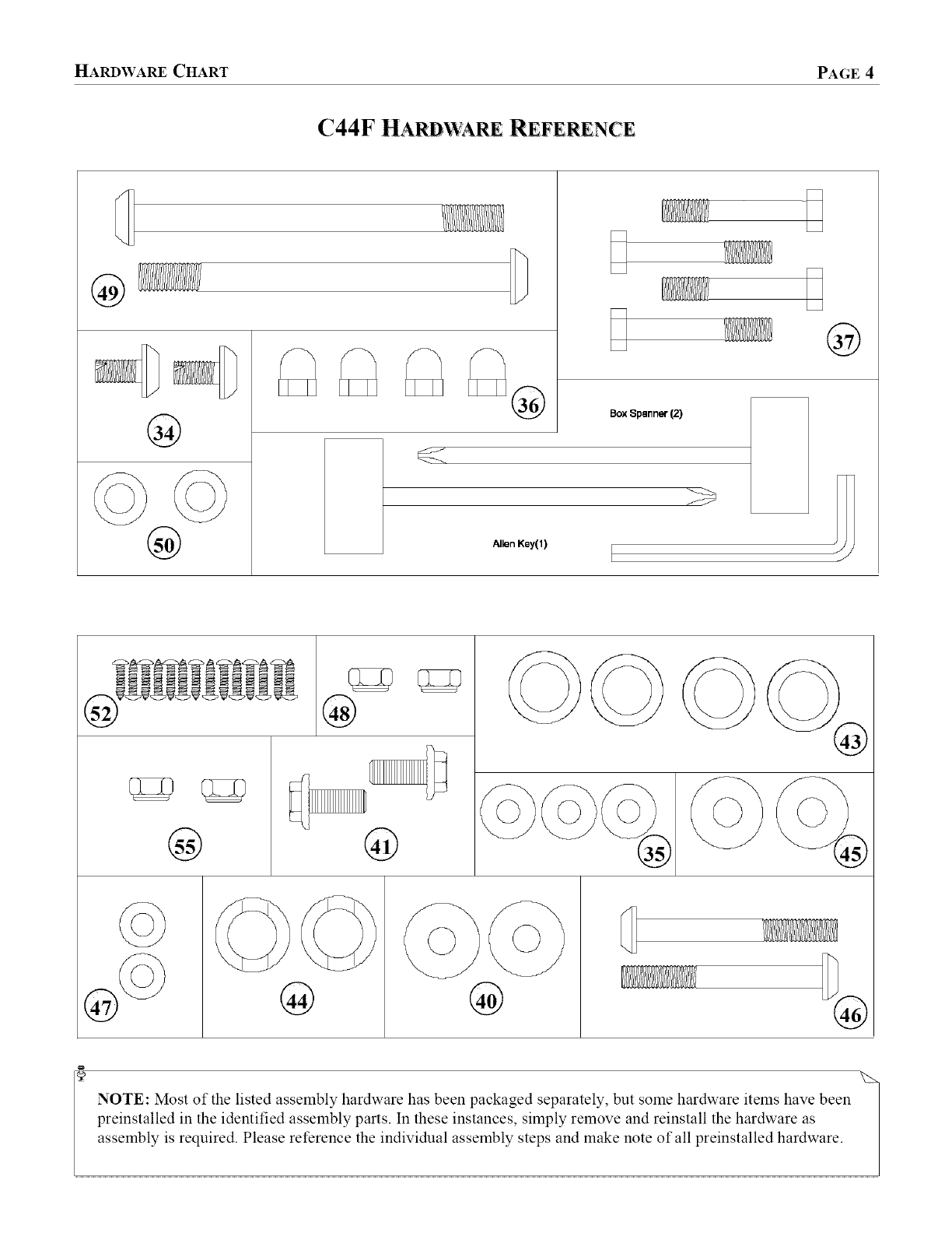
C44F HARDWARE REFERENCE
®
@
@
D
BoxSpanner(2)
Allen Key(l)
©
@
®
®
@
NOTE: Most of the listed assembly hardware has been packaged separately, but some hardware items have been
preinstalled in the identified assembly parts. In these instances, simply remove and reinstall the hardware as
assembly is required. Please reference the individual assembly steps and make note of all preinstalled hardware.
PAGE 5 EXPLODED PARTS VIEW
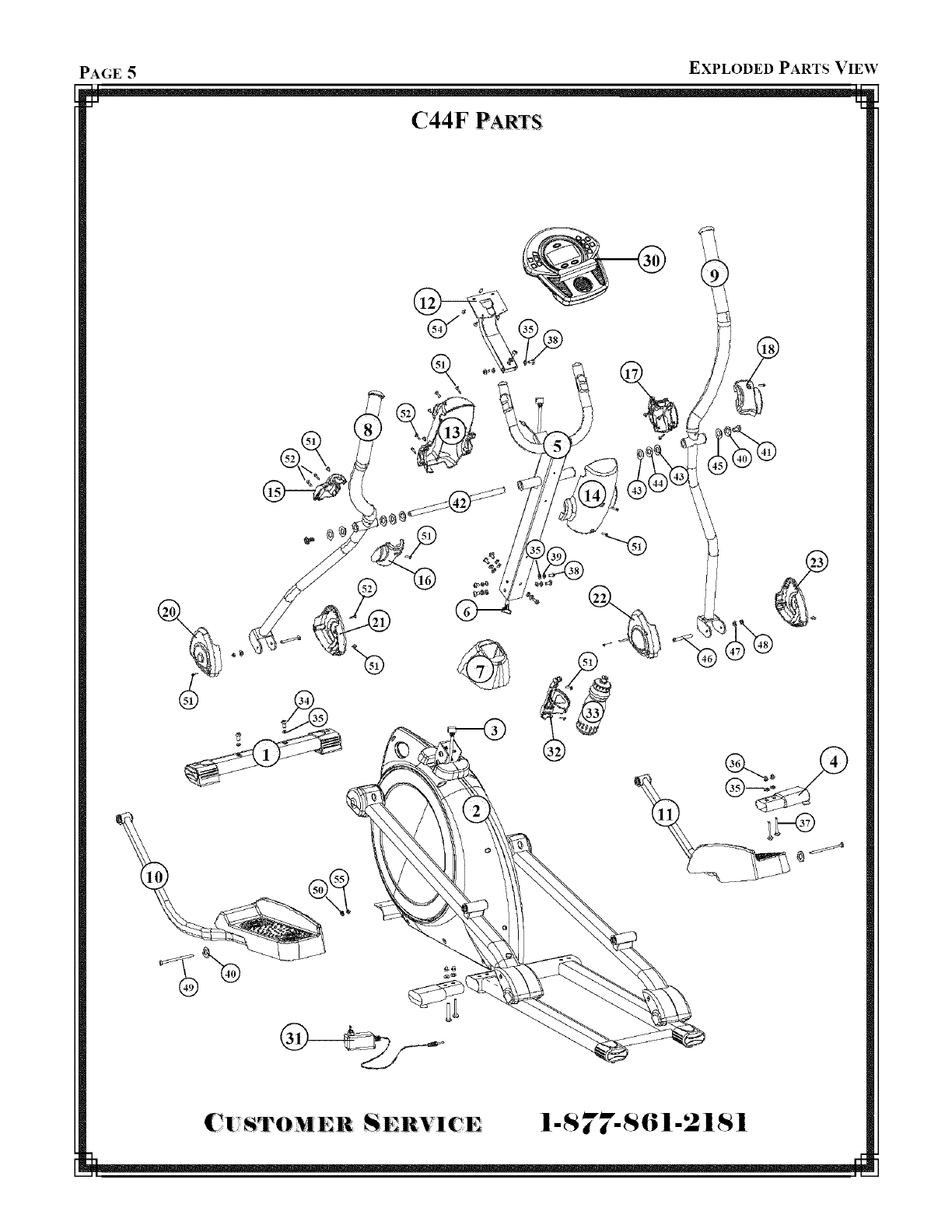
C44F PARTS
C|,_S_TOMER SERVlCE I-S 77-$61-21S1
ASSEMBLY INSTRUCTION PAGE 6
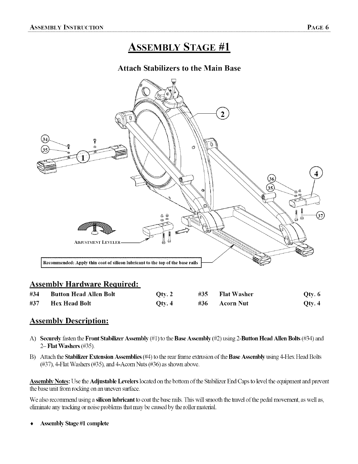
ASSEMBLY STAGE #1
Attach Stabilizers to the Main Base
lRecommended: Apply thin coat of silicon lubricant to the top Of the base rails
Assembly Hardware Required:
#34 Button Head Allen Bolt Qty. 2 #35 Flat Washer
#37 Hex Head Bolt Qty. 4 #36 Acorn Nut
Qty. 6
Qty. 4
Assembly Description:
A) Securely _hsten the Front Stabilizer Assembly (# 1) to the Base Assembly (#2) using 2-Button Head Allen Bolts (#34) and
2- Flat Washers (#35).
B) Attach the Stabilizer Extension Assemblies (#4) to the rear flame extrusion of the Base A_ssembb"using 4-Hex Head Bolts
(#37), 4-Flat Washers (#35), and 4-Acom Nuts (#36) as shown above.
Assembly Notes: Use the Adjustable Levelers located on the bottom of the Stabilizer End Caps to level the equipment and prevent
the base unit from rocking on an uneven surthce.
We also recorrnnend using a silicon lubricant to coat the base rails. This will smooth the travel of the pedal movement, as well as,
eliminate any tracking or noise problems that may be caused by the roller material.
• A_ssembly Stage #1 complete
PAGE 7 ASSEMBLY INSTRUCTION
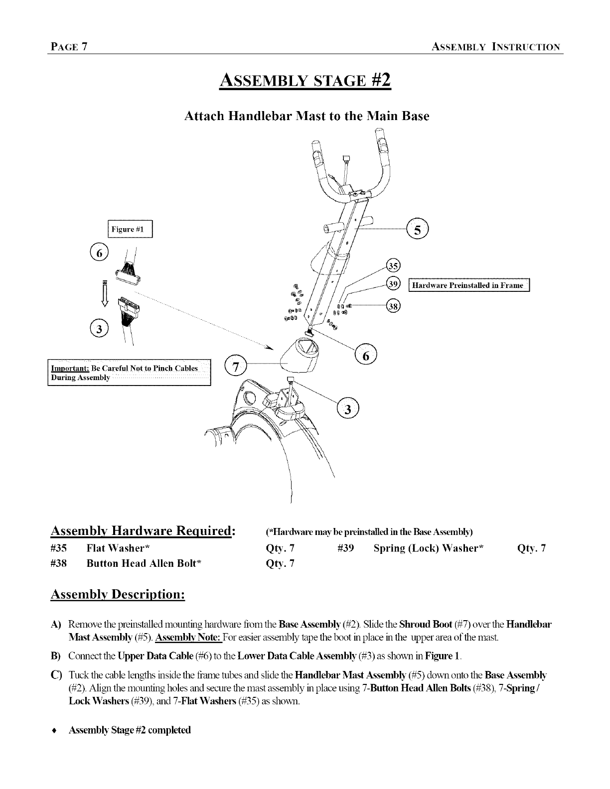
ASSEMBLY STAGE #2
Attach Handlebar Mast to the Main Base
IFigure #1
Be Careful Not to Pinch Cables ]
During Assembly ]
®
[Hardware Preinstalled in Frame I
Assembly Hardware Required:
#35 Flat Washer*
#38 Button Head Allen Bolt*
(*Hardware may be pveinstalled in the Base Assembly)
QD:. 7 #39 Spring (Lock) Washer*
Qty. 7
Qty. 7
Assembly Description:
A) Remove the preinstalled mounting hardware from the Base Assembly (#2). Slide the Shroud Boot (#7) over the Handlebar
_MastAssembly (#5). Assembly Note: For easier assembly tape the boot in place in the upper area of the mast.
B) Connect the Upper Data Cable (#6) to the Lower Data Cable Assembly (#3) as shown in Figure 1.
C) Tuck the cable lengths inside the flame tubes and slide the Handlebar Mast Assemb b"(#5) down onto the Base Assemb b"
(#2). Align the mounting holes and secure the mast assembly in place using 7-Button Head Allen Bolts (#38), 7-Spring /
Lock Washers (#39), and 7-Flat Washers (#35) as shown.
• Assembly Stage #2 completed

ASSEMBLY INSTRUCTION PAGE 8
ASSEMBLY STAGE #3
Attach Upper Pivot Arms to the Handlebar Mast
Assembly Hardware Required:
#40 Flat Washer Qty. 2
#41 Hex Head Flange Bolt Qty. 2
#43 Flat Washer Qty. 4
#44 Wave Washer Qty. 2
#45 Thin Teflon Washer Qty. 2
Assembl v Description:
A) Slide the Threaded Pivot Shaft (#42) through the pivot-boss of the Handlebar Mast (#5). Over each end of the shall slide
1-Flat Washer (#43), 1-Wave Washer (#44), and 1-Flat Washer (#43) following the orientation shown.
B) Slide the Left Pivot Arm Assemb b" (#8) over the end of the Pivot Shaft (#42). Secure the ann to the shaft using 1-Teflon
Washer (#45), 1-Flat Washer (#40), and 1-I-IexHead Flange Bolt (#41) tbllowing the orientation shown. Note: Loose_
tighten the Flange Bolt until the Right Pivot Ann is in place.
C) Repeat the assembly ret_rence tbr attaching the Right Pivot Arm Assembly (#9) to the Pivot Shaft (#42). Secure the arm in
place using 1-Teflon Washer (#45), 1-F"latWasher (#40), and 1-I-Iex Head Flange Bolt (#41) tblk_ving the orientation
shown.
D) Fully tightenthe m(mntmghardware tbr each pivotann. Silnultaneouslytightenthe mountinghardware by turningthe Hex
Head Flange Brits in oplx_sitedirectkms,as referencedby the arrows.
•Assembly Stage #3 completed
PAGE 9 ASSEMBLY INSTRUCTION
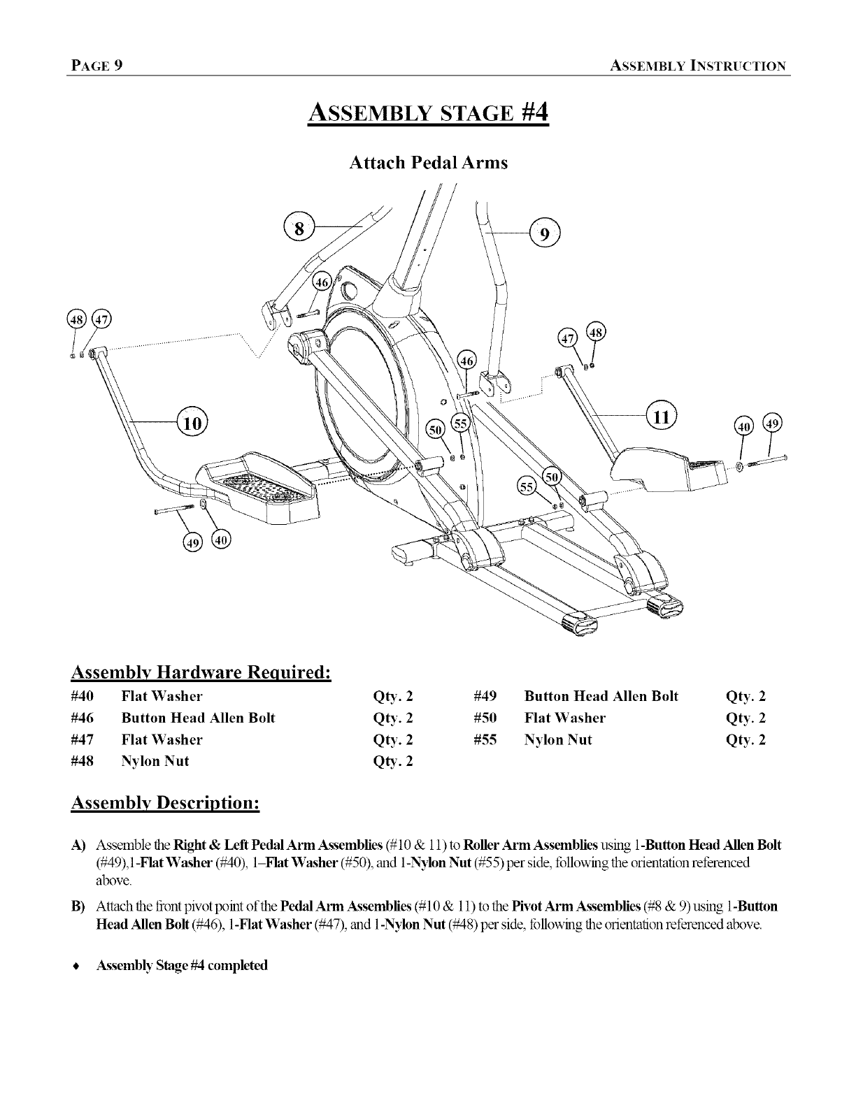
ASSEMBLY STAGE #4
Attach Pedal Arms
/:
Assembly Hardware Required:
#40 Flat Washer QD_. 2
#46 Button Head Allen Bolt Qty. 2
#47 Flat Washer Qty. 2
#48 Nylon Nut QD'. 2
#49 Button Head Allen Bolt Qty. 2
#50 Flat Washer Qty. 2
#55 Nylon Nut Qty. 2
Assembly Description:
A) Assemble the Right &Left Pedal Arm Assemblies (# 10 & 11) to Roller Arm Assemblies using 1-Button Head Allen Bolt
(#49), 1-Flat Washer (#40), 1-Flat Washer (#50), and 1-N31on Nut (#55) per side, fbllowing the orientation ret_renced
above.
B) Attach the front pivot point of the Pedal Arm Aossemblies (# 10 & 11) to the Hvot Arm Assemblies (#8 & 9) using 1-Button
Head Allen Bolt (#46), 1-Hat Washer (#47), and 1-Nylon Nut (#48) per side, tbllt_ving the orientation referenced above.
•Atssembly Stage #4 completed
ASSEMBLY INSTRUCTION PAGE 10
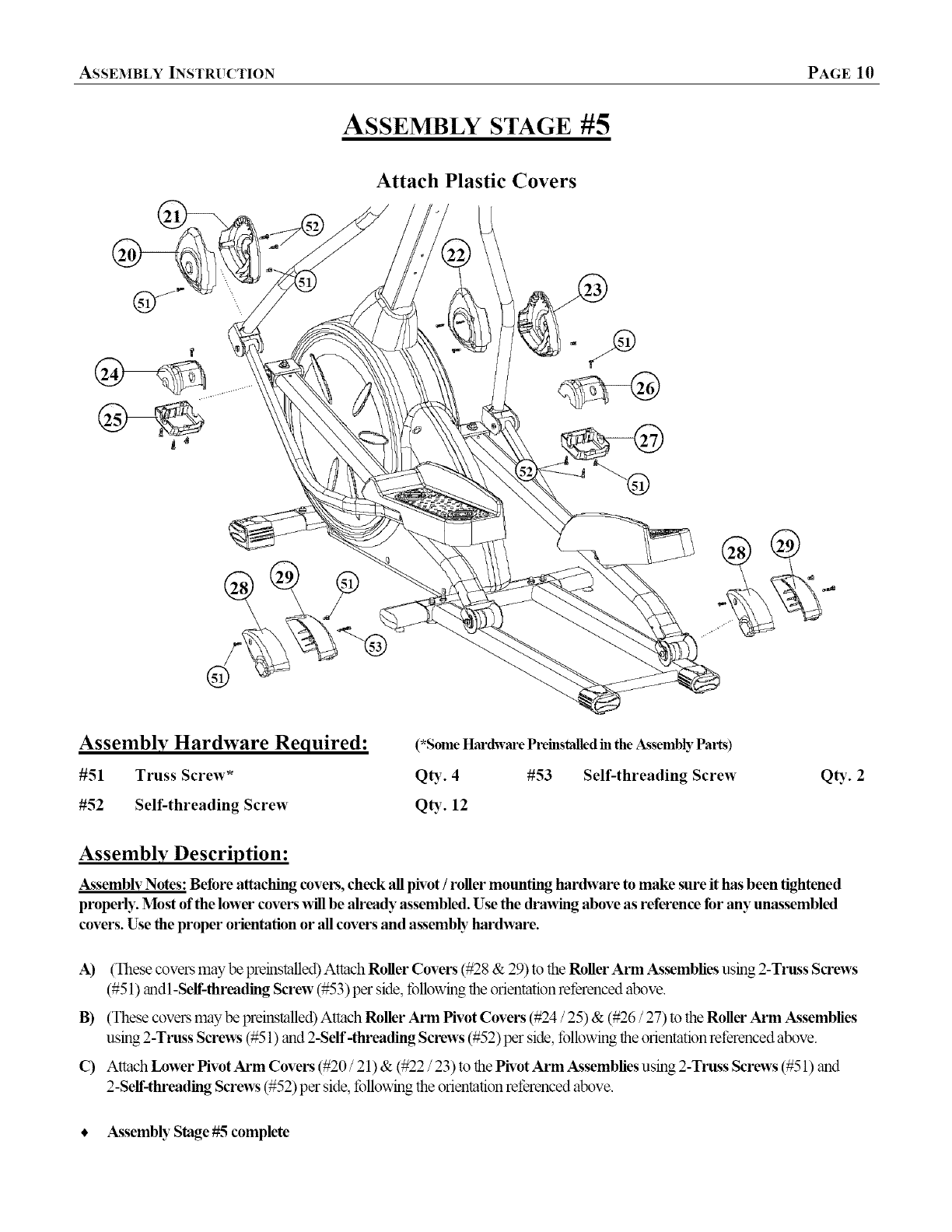
ASSEMBLY STAGE #5
Attach Plastic Covers
Assembly Hardware Required:
#51 Truss Screw _
#52 Self-threading Screw
(*Some Hardware Preinstalledin the Assembly Pal_s)
QD_. 4#53 Self-threading Screw
12
Q_,. 2
Assembly Description:
A_ssemblv Notes: Before attaching covers, check all pivot /roller mounting hardware to make sure it has been tightened
properly. Most of the lower covers x_fllbe already assembled. Use the draxv_ng above as reference for any unassembled
covers. Use the proper orientation or all cove_ and assembh _hardware.
A) (These covers may be preinstalled) Attach Roller Covers (#2g & 29) to the Roller Arm Assemblies using 2-Truss Screws
(#51) andl-Serf-threading Screw (#53) per side, lbllowing the orientation rel_renced above.
B) (These covers may be preinstalled) Attach Roller Arm Pivot Covers (#24 /25) & (#26 /27) to the Roller Arm Assemblies
using 2 -Truss Screws (#51) and 2-Self -threading Screws (#52 ) per side, lbllowing the orientation rel_renced above.
C) Attach Lower Pivot Arm Covers (#20 /21) & (#22 /23) to the Pivot Arm Assemblies using 2-Truss Screws (#51 ) and
2-Self-threading Screws (#52) per side, l_bllowingthe orientationrel_renced above.
• A_ssembly Stage #5 complete
PAGE 11 ASSEMBLY INSTRUCTION
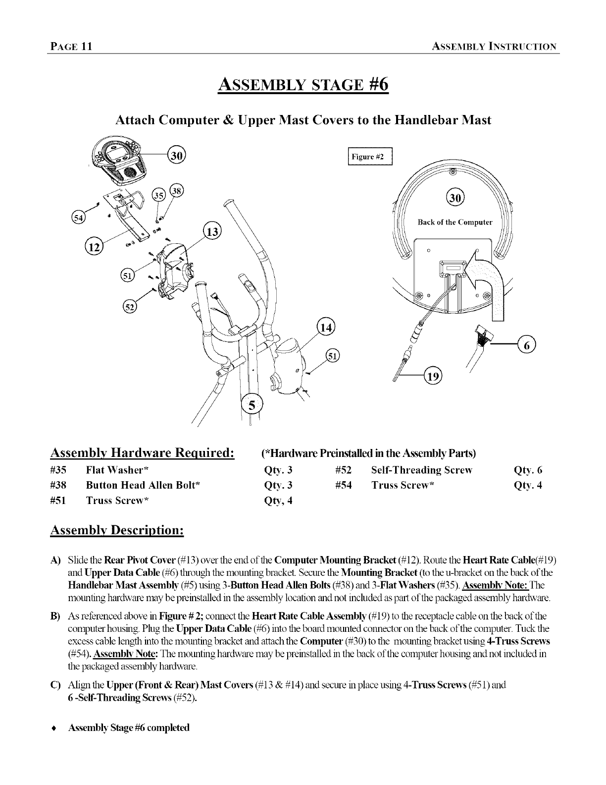
ASSEMBLY STAGE #6
Attach Computer & Upper Mast Covers to the Handlebar Mast
Figure #2 ]
Assembly Hardware Required:
#35 Flat Washer*
#38 Button Head Allen Bolt*
#51 Truss Screw*
(*Hardware Preinsl'_ed in the Assembly Pa_s)
QU- 3 #52 Self-Threading Screw
Qty. 3 #54 Truss Screw*
QD _,4
Qty. 6
Qty. 4
Assembly Description:
A) Slide the Rear Pivot Cover (# 13) over the end of the Computer Mounting Bracket (#12). Route the Heart Rate Cable(# 19)
and Upper Data Cable (#6) through the mounting bracket. Secure the Mounting Bracket (to the u-bracket on the back of the
Handlebar Mast Assemb b"(#5) using 3-Button Head Allen Bolts (#38) and 3-Flat Washers (#35). Assembly Note: The
mounting hardware may be preinstalled in the assembly location and not included as part of the packaged assembly hardware.
B) As retbrenced above in Figure #2; connect the Heart Rate Cable Assembly (#19) to the receptacle cable on the back of the
computer housing. Plug the Upper Data Cable (#6) into the board mounted connector on the back of the computer. Tuck the
excess cable length into the mounting bracket and attach the Computer (#30) to the mounting bracket using 4-Truss Screws
(#54). Assembh _Note: The mounting hardware may be preinstalled in the back of the computer housing and not included in
the packaged assembly hardware.
C) Align the Upper (Front & Rear) Mast Covers (# 13 & # 14) and secure in place using 4-Truss Screws (#51 ) and
6-Serf-Threading Screws (#52).
•Assembly Stage #6 completed

ASSEMBLY INSTRUCTION PAGE 12
ASSEMBLY STAGE #7
Attach Upper Pivot Covers & Water Bottle Cage
Assembly Hardware Required: (*HardwarePreinstalledintheAssembh_Parts)
#51 Truss Screw _ QD:- 4 #52 Self-threading Screw
Assembly Description:
Qty. 4
Assembly Note: Before attaching the Pivot Cover_ check the Pivot Arm mounting hardware to make sure it has been
tightened properh,.
A) Mount the Upper Front Pivot Covers (# 16 & # 18) to the front end of the Ph'ot Arms (#8 & #9) using 1-Truss Screw* per
cover.
B) Attach the Upper Rear Pivot Covers (#15 & #17) using 1-Truss Screw* (#51) and 2-Self-Threading Screws (#52) per side
as shown.
C) Attach the Bottle Cage (#32) to the Handlebar Mast (#5) using the 2-_eviously installed Truss Screws (#51). Once the cage
has been mounted_ insert the Sports Bottle (#33).
•A_ssembly Stage #7 complete
PAGE 13 ASSEMBLY INSTRUCTION
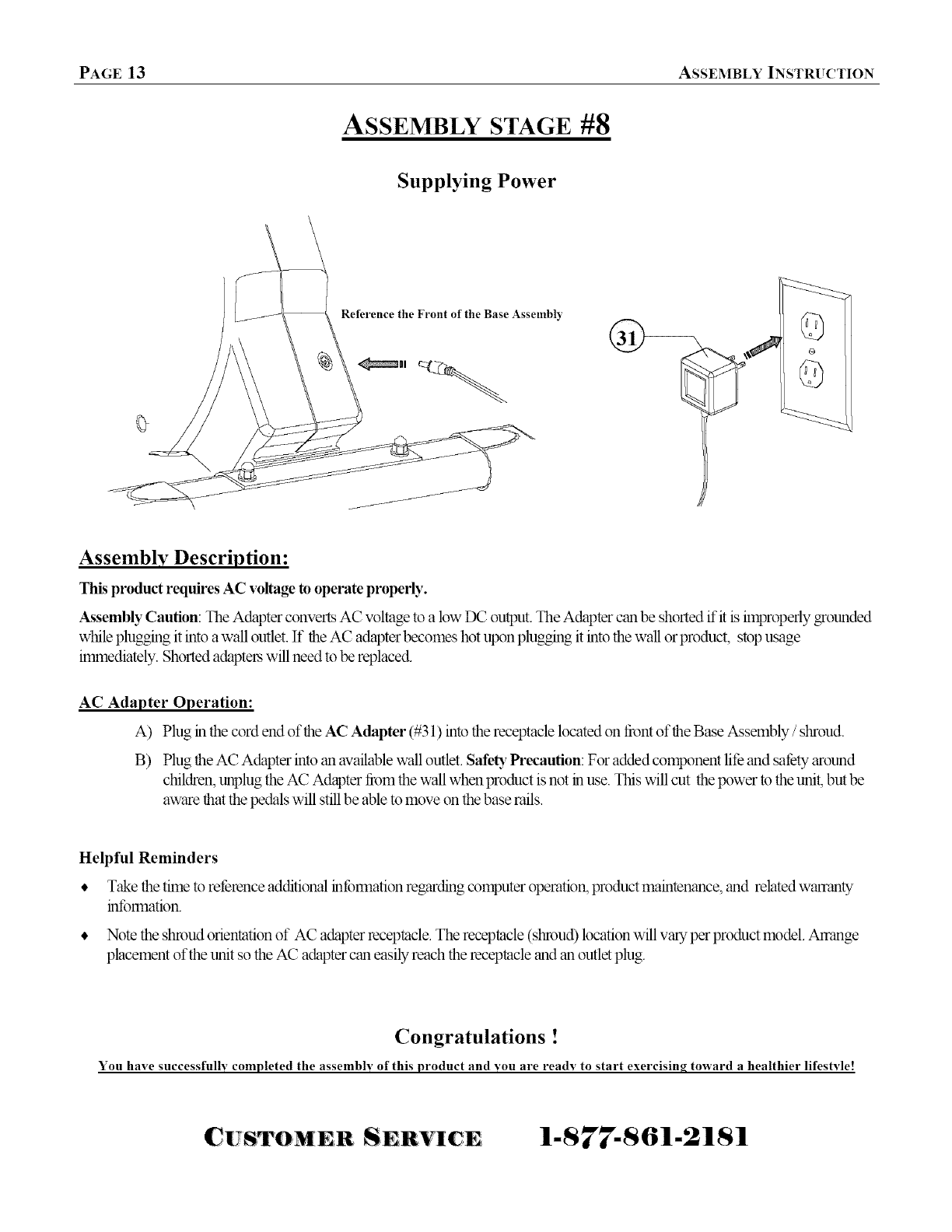
ASSEMBLY STAGE #8
Supplying Power
Reference the Front of the Base Assembly
<_mul q_7_
Assembly Description:
This product requires AC voltage to operate properly.
A_ssembly Caution: The Adapter cx_nvertsAC voltage to a low DC output. The Adapter can be shorted it'it is improperly grounded
while plugging it into a wall outlet. If the AC adapter becomes hot upon plugging it into the wall or product, stop usage
immediately. Shorted adapters will need to be replaced.
AC Adapter Operation:
A) Plug in the cord end of the AC Adapter (#31 ) into the receptacle located on front of the Base Assembly /shroud.
B) Plug the AC Adapter into an available wall outlet. SafeD TPrecaution: For added comlxment lit_ and satbty around
children, unplug the AC Adapter from the wall when product is not in use. This will cut the Ix_wer to the unit, but be
aware that the pedals will still be able to move on the base rails.
Helpful Reminders
• Take the time to ret_rence additional intbrmation regarding computer operation, product maintenance, and related warranty
intbrmation.
• Note the shroud orientation of AC adapter receptacle. The receptacle (shroud) location will vary per product model. Arrange
placement of the unit so the AC adapter can easily reach the receptacle and an outlet plug.
Congratulations !
You have successfulh, completed the assembh, of this product and you are ready to start exercisinq toward a healthier lifestyle!
CUSTOM n S HVIC 1-877-861-2181
COMPUTER OPERATION PAGE 14
COMPUTER |NSTRU_|ON
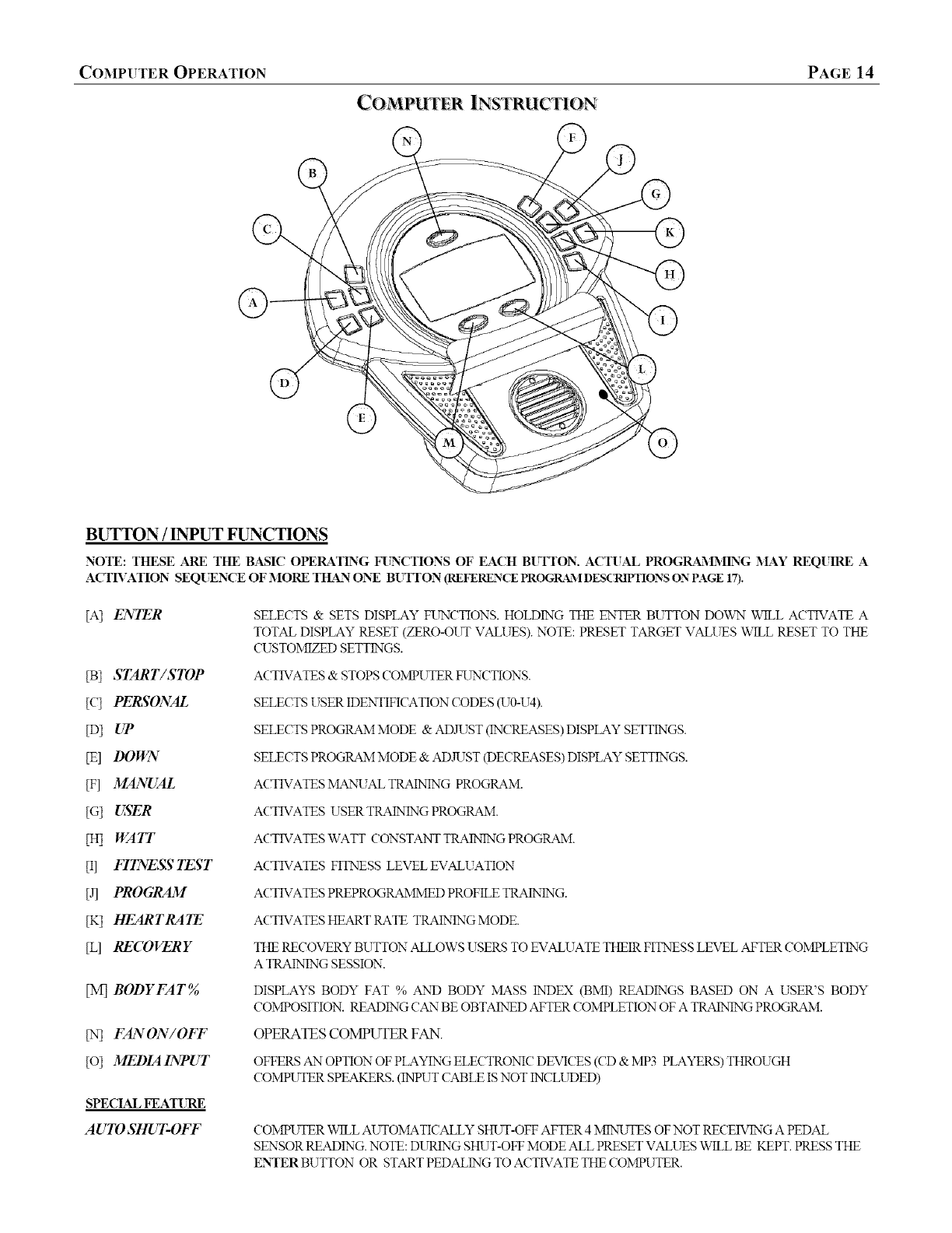
BUTTON /INTUT FUNCTIONS
NOTE: THESE ARE THE BASIC OPERATING FI_CTIONS OF EACH B[YFTON. ACTUAL PROGRA_'_LMING MAY REQUIRE A
ACTB'ATION SEQI_NCE OF MORE THAN ONE BUTTON (REFERENCEPROG1LL\IDESC_dVfIONSON PAGE 17).
[A] ENTER
[B] START/STOP
[c] PERSONAL
[D] UP
[E] DOWN
[F] MANUAL
[G] USER
[HI WAIT
[I] FI1WE,_7 TEST
[J] PROGRAM
[K] HEAR TRA TE
[L] RECOVERY
[M] BODYFAT%o
IN] FANON/OFF
[o] MEDIA INPUT
SPECIAL FEAT[_
AUTO SHUT-OFF
SELECTS & SETS DISPLAY FUNCTIONS. HOLDING THE ENTER BUTTON DOWN WILL ACTIVATE A
TOTAL DISPLAY RESET (ZERO-OUT VALUES). NOTE: PRESET TARGET VALUES WILL RESET TO THE
CUSTOMIZED SETTINGS.
ACTIVATES & STOPS COMPUTER FUNCTIONS.
SELECTS USER IDENTIFICATION CODES (U0-U4).
SELECTS PROGRAM MODE & AD,R_ST(INCREASES) DISPLAY SETTINGS.
SELECTS PROGRAM MODE & ADJUST (DECREASES) DISPLAY SETTINGS.
ACTIVATES MA_NXTALTRAINING PROGRAM.
ACTIVATES USER TRAINING PROGRAM.
ACTIVATES WATT CONSTANT TRAINTNG PROGRAM.
ACTIVATES FITNESS LEVEL EVALUATION
ACTIVATES PREPROGRAMMED PROFILE TRAINING.
ACTIVATES HEART RATE TRAINEXTGMODE.
THE RECOVERY BUTTON ALLOWS USERS TO EVALUATE THEIR FITNESS LEVEL AFTER COI\&LETING
A TRAINING SESSION'.
DISPLAYS BODY FAT % AND BODY MASS INDEX (BMI) READINGS BASED ON A USER'S BODY
COMPOSITION. READING CTANBE OBTAINED AFTER COMPLETION OF A TRAINING PROGRAM.
OPERATES COMPUTER FAN.
OFFERS AN OPTION OF PLAYING ELECTRONIC DEVICES (CD & MP3 PLASTERS)THROUGH
COMPUTER SPEAKERS. (INPUT CABLE IS NOT INCLUDED)
COMPWFER WILL AUTOMATICALLY SHUT-OFF AFTER 4 MIN_UTES OF NOT RECEIVING A PEDAL
SENSOR READING. NOTE: DUREXTGSHUT-OFF MODE ALL PRESET VALUES WqLL BE KEPT. PRESS THE
ENTER BUTTON OR START PEDALING TO ACTIVATE THE COMPUTER.

PAGE 15 COMPUTER OPERATION
©
COMPUTER INSTRUCTION
1) ACTIVATION (START UP)
MAKE SURE THE AC ADAPTER IS PROPERLY PLUGGED IN'TO A WALL OWIZET. PRESS ANY FUNCTION BUTTON
OR START PEDALIN'G TO ACTIVATE DISPLAY. A BEEP WILL SOL_,,T) ANT) THE DISPLAY WILL ILLUMINATE.
2) SET UP STEPS
2.1 ONCE ACTIVATED, THE DISPLAY WILL SHOW A SCREEN WITH STOP BLINKING IN THE LOWER LEFT CORNER
AND A USER ID CODE (U0-U4) BLINKING IN THE UPPER LEFT CORNER. AT THIS POINT A USER ID MUST BE
SELECTED; USE THE PERSONAL BUTTON TO SCROLL THROUGH THE USER ID OPTION'S AND PRESS THE ENTER
BLFFTON TO LOCK IN"THE DESIRED USER ID.
U0 QUICKER SETUP PROCESS WITH LIMITED PROGRAivLMINGOPTION'S.
U1- U4 = MORE PROGRAMMIN'G OPTION'SINCLUDING CUSTOMIZED DATA ENTRY.
22 IF USER ID CODE U1474 IS CHOSEN. THE USER WILL BE PROMPTED (BLINKING DISPLAY TEXT) TO ENTER
PERSONAL DATA (GENDER_AGE, HEIGHT, AND WEIGHT). THIS DATA WILL BE USED TO CALIBRATE THE
TRAINING PROGRAMS.
IF USER ID U0 IS CHOSEN, THE DISPLAY WILL AUTOMATICALLY SKIP PERSONAL DATA ENTRIES AND MOVE
TO THE TRAINING PROGRAM SELECTIONS.
23
2A
ONCE THE USER ID ISDEFINED AND PERSONAL DATA IS ENTERED, THE USER WILL BE PROMPTED (BL1NKINTG
TEXT) TO SELE(T A TRAINING PROGRAM (MANUAL, FITNESS TEST, WATT, PROGRAM, HEART RATE CONTROL.,
OR USER). ALL PROGRAM HEADINGS WILL BE LISTED ACROSS THE TOP OF THE S(TREEN.THE PROGRAM
SELECTION WILL VARY DEPENDING ON THE USER ID SELE(TED. PUSH THE CORRESPONDING BUTTON (ON THE
RIGHT SIDE OF THE COMPUTER) TO CHOOSE A DESIRED PROGRAM. (See page 18)
AFTER SELE(TING A TRAINTNGMODE, THE USER griLL HAVE THE OPTION TO PRESET TARGET VALUES FOR THE
INDIVIDUAL DISPLAY FL_'(TIONS (TIME, DISTANCE, CALORIE, AND HEART RATE). THESE TARGET VALUES
WILL BE IDD<TIFIED WqTHBL1NKL\TGTEXT. USE THE IT OR DO_2_" BUTTON TO ADJUST VALUES AND PRESS
THE ENTER BUTTON TO LOCK IN"THE DESIRED PRESETS. THE ENTER BUTTON CAN ALSO BE USED TO SCROLL
THROUGH EA(THTARGET WINI)OW OR A USER CAN SKIP ALL TARGET SETUP BY PUSHING THE START /STOP
TO BEGIN"TRAINING. NOTE: DISPLAY FUNCTIONS WILL COUNT UP FROM ZERO DtlEN NO VALUES ARE PRESET.
QUICK START AFTER A USER ID IS CHOSEN. PRESS THE _IANTTALPROGRAM BUTTON. NEXT; PRESS THE START /STOP
BUTTON AND BEGIN"TRAINING. ALL DISPLAY VALUES WqLL COUNT UP FROM ZERO, LNLESS PRESET VALUES
WERE PREVIOUSLY ENTERED. NOTE: IF USING U0 USER ID; PRESS THE START /STOP BUTTON. THE COMPUTER
WILL AUTOMATICALLY GO INTO MANUAL TRAD,TNGMODE.
RESISTANCE PRODUCT IS EQUIPPED WITH AN ADJUSTABLE RESISTANCE MECHANISM. THIS FEATURE WILL ALLOW A USER
TO CHOOSE FROM 1- 16LEVELS OF VARIED RESISTANCE. A USER CAN ADAJST RESISTANCE AT ANY TIME
DURING A ]]ZAIN_qG MODE BY PUSHING THE IT DOBN BUTTONS (THE EXCEPTION WOL_D BE THE TARGET
HEART RATE MODE). NOTE: PREPROGRAMMED TRAINING PROFILES WILL NOT ALLOW THE RESISTANCE
LEVELS TO BE ADJUSTED BEYOND THE MINIMAL SETTINGS
ERROR CODES E1 BODY FAT MEASUREMENT FAILED DUE TO INCORRECT HEART RATE READING. (Seepage 19)
E2 BAD DATA CABLE CON%TCTION. (Seepage 19)

COMPUTER OPERATION PAGE 16
COMPUTER INSTRUCTION
DISPLAY FUNCTIONS /RE,M)LNGS
TIME
SPEED
RIM
DISTANCE
CALORIE
PULTE
WATT
RECOVERY
COMPLFFERDISPLAY WILL ACCXJlVRJ'LATETOTAL TRAINING TIME IN 00:00(MINCJTES :SECONDS). COMPUTER
WILL COUNT UP TO, OR DOWN FROM, A MAXIMUM READING OF 99:59.
PRESET TARGET TRAINING TgIE: USE THE ENTER BUTTON TO SCROLL TO _ TIME FUN(TION AND USE
THE UP /DO_TN BUTTONS TO AD,R_STTHE SETTD_G. SETTINGS V_qLLBE ENTERED LN 1:00MINLFFELNCREMENTS
AND THE COMPUTER WILL COUNT DOWN FROM THE SET TIME. ONCE THE DESIRED TIME IS SET, PRESS START /
STOP BUTTON TO BEGIN TRAINING. ONCE A SET TRAINING TIME IS COMPLETED, THE COMPLFFERXaqLL"BEEP"
FOR APPROXIMATELY 8 SECONDS AND COMPUTER WILL RESET TO THE INTHAL SETTING.
THE COMPLFYERXAqLLREGISTER At\i) DISPLAY TRAINING SPEED (MPH).
THE COMPLFYERXAqLLREAD At\i) DISPLAY PEDAL /DRIVE TRAhN ROTATIONS.
THE COMPUTER ACCUMULATES TRAINING DISTANCE FROM 0.00TO A MAXIIVRJMOF 99.90 MILES. EACH
LNCREMENT WILL BE DISPLAYED 1N 0.01 MILE.
PRESET A TARGET TRAENING DISTANCE: USE THE ENTER BLFITON TO SCROLL TO THE DISTANCE FUNCTION
WL\I)OW AND USE THE 1_ /DO%%_ BUTTONS TO AD,RJST THE SETTING. EACH SETTING WILL BE LN
INCREMENTS OF 0.10 MILE AtNDTHE COMPUTER WILL COUNT DOXArNFROM THE SET DISTAtNCE.ONCE THE
DESIRED DISTAtNCE IS SET, PRESS THE START /STOP BUTTON TO BEGIN TRADING. ONCE ATARGET DISTANCE
IS ACHIEVED, THE COMPLFFER WILL "BEEP" FOR APPROXIMATELY 8 SECONDS AND RESET TO THE INTHAL
SETTINGS.
COMPLFYERACCUMULATES TOTAL CALORIE CONSUMPTION (BUP,xN)DURING A TRAINING PERIOD. COMPLFYER
WILL COUNT IN 1CALORIE L\'CREMENTS, FROM 0 TO AMAXIIVRTMREADING OF 9990 CALORIES.
PRESET A TARGET CALORIE BURN: USE THE ENTER BUTTON TO SCROLL TO THE CALORIE FUNCTION AN USE
THE UP /DO_VN BUTTONS TO ADJUST THE SETTING. ADJUSTED VALUES WILL BE ENTERED IN INCREMENTS OF
10CALORIES At\i) THE COMPUTER WILL COUNT DOWN FROM THE SET CALORIE BURN. ONCE THE CALORIE
FUN(TION IS SET, PRESS START /STOP BUTTON TO BEGIN TRAINING. ONCE THE TARGET CALORIE BURN IS
ACHIEVED, THE COMPUTER WILL "BEEP" FOR APPROXIMATELY 8 SECONDS AND THEN RESET TO THE
ORIGINAL SETTING.
NOTE: THE REPORTED CALORIE DATA IS ONLY A REFERENCE GUIDE FOR THE USER, IT SHOULD NOT BE USED
LNCOMPARISON OF CALIBRATED MEDICAL EQUIPMENT.
THE COMPLFFERCAtNDISPLAY A USER'S HEART RATE READING. A BLINKING HEART S'_qVIBOL& NUMERIC
READING WILL BE DISPLAYED ON THE (7OMPUTER AS LONG AS A USER'S HAtNDS ARE LOCATED ON THE GRIP
SENSORS. READINGS WILL APPEAR WITHIN 30SECONDS TO 1 MINUTE OF CONSISTENT GRIP CONTACT.
READINGS WILL BECOME IN(YONSISTENTIF A USER FAILS TO LEAVE BOTH HAtNDSIN CONTA(?T WITH THE GRD
SENSORS.
PRESET A TARGET HEART RATE: USE THE ENTER BUTTON TO SCROLL TO THE HEART RATE FI_JNC?TIONAND
PRESS THE UP /DOX'_,N"BUTTONS TO AD,R?ST THE SETTLNG.Pt_SE SETTINGS WqLLBE FROM 30 - 240 BPM.
ONCE THE DESIRED HEART RATE IS SET PRESS THE START /STOP BUTTON TO BEGIN TRAINING. IF A USER
EXCEEDS THE SET TARGET HEART RATE, THE COMPLFFERWILL "BEEP" TO REMIND THE USER OF THE PRESET
LIMIT.
NOTE: HEART RATE READINGS ARE ONLY A REFERENCE OF A USER'S PULSE RATE DURING TRA_IN'G. THESE
READOUTS SHOULD NOT BE USED 1NCOMPARISON WITH CALIBRATED MEDICAL EQUIPMENT. SOME USERS
MAY EXPERIENCE D,Z'ONSISTENCIES IN READINGS DUE TO THE NATURE OF THEIR PHYSICAL CONDITION.
THE COMPUTER WILL MEASURE A USER'S TRAINING OUTPUT (WORKLOAD). THE COMPUTER WILL
AUTOMATICALLY CONFIGURE AND DISPLAY WATT READINGS DURING ALL TRAINING MODES. READINGS
WILL BE DISPLAYED IN 1-WATT INCREMENTS. (Refh"to the WATT progmn to wainusing a prepromammed setting)
THE COMPUTER WILL ALLOW A USER TO EVALUATE THEIR FITNESS LEVEL AFTER COMPLETING A TRAINING
SESSION. THE EVALUATION IS BASED ON A USER'S HEART RATE RECOVERY. ACTB'ATION: AFTER
COMPLETING A TRAINING SESSION, PRESS THE RECOVERY BUTTON AtXi) PLACE PALMS OF BOTH HANDS ON
THE SENSOR GRIPS. THE COMPUTER griLL AI_OMATICALLY STOP ALL DISPLAY FUNCTIONS EXCEPT "TIME",
DttICH WILL START COL_,'TING DOWN FROM 60 SECONDS. ONCE THE COUNT DOWN ISCOMPLETED, THE USER
('AN REMOVE THEIR HAtXI)S FROM THE SENSOR GRIPS. THE BOTTOM DISPLAY WILL SHOW A RATING OF F 1 F6.
AN 'T 1"READING IS THE BEST RATING POSSIBLE. USERS ('AN MONITOR THEMSELVES AFTER EACH TRAINING
SESSION AtNi) USE THE RE(70VERY READING AS A GAUGE FOR CARDIO (7ONDITIONING.
NOTE: PRESS THE RECOVERY BLFITON AGAIN TO RETURN TO THE MAIN DISPLAY.
PAGE 17
COMPUTER INSTRUCTION
DISPLAY FUNCTION /READ_GS (Continued)
COMPUTER OPERATION
BODY FAT %
(1ST#)
(2ND#)
(SYMBOL)
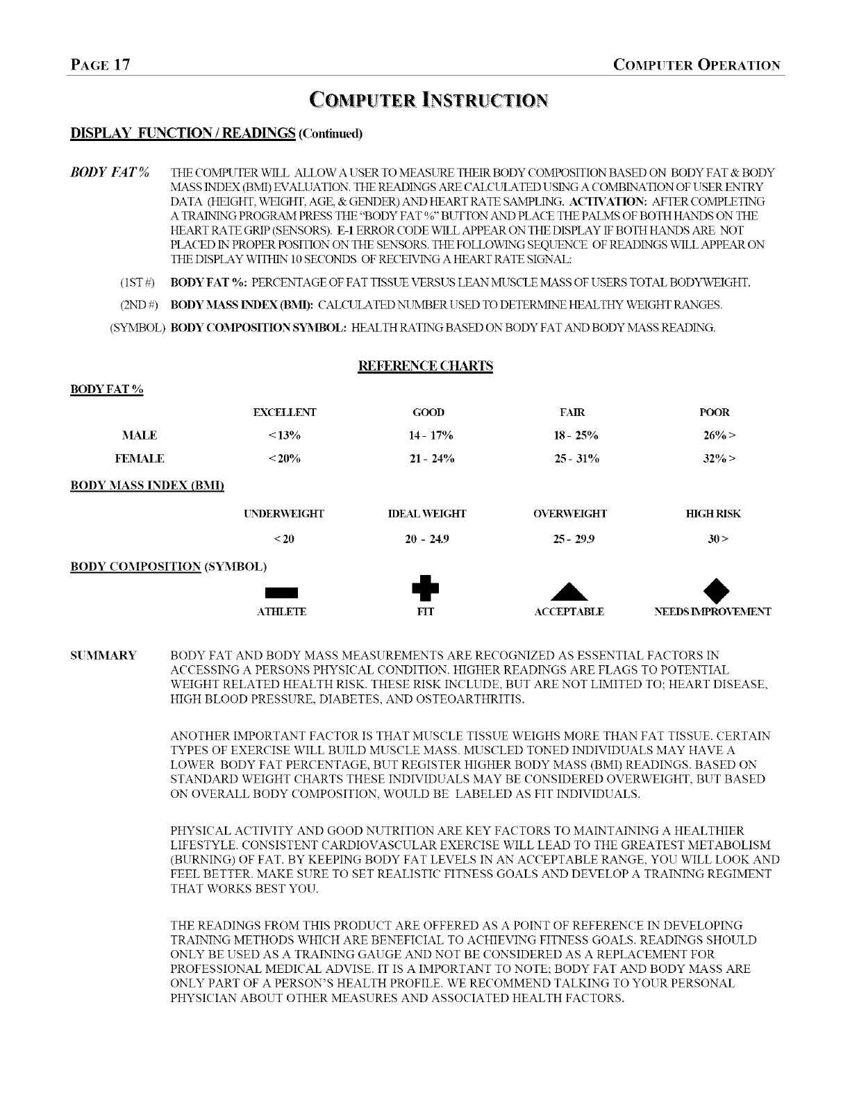
THE COMPUTER V_qLLALLOW A USER TO MEASURE THEIR BODY COMPOSITION BASED ON BODY FAT & BODY
MASS ENDEX(BMI) EVALUATION. THE READINGS ARE CALCULATED USING A COMBINATION OF USER ENTRY
DATA (HEIGHT, WEIGHT, AGE, & GENDER) AND HEART RATE SAMPLING. ACTIA'ATION: AFTER COMPLETING
ATRAINTNG PROGRAM PRESS THE "BODY FAT %" BUTTON AXD PLA(TETHE PALMS OF BOTH HANDS ON THE
HEART RATE GRIP (SENSORS). E-1 ERROR (70DE WILL APPEAR ON THE DISPLAY IFBOTH HANDS ARE NOT
PLACED ENPROPER POSITION"ON THE SENSORS. THE FOLLOWING SEQUENCE OF READINGS WILL APPEAR ON
THE DISPLAY WITHIN"10 SECONDS OF RECEIVING A HEART RATE SIGNAL:
BODY FAT %: PERCENTAGE OF FAT TISSUE VERSUS LEAN MUSCLE MASS OF USERS TOTAL BODYWEIGHT.
BODY MASS [N'DEX (BM1): CAL(VLATED NXYMBERUSED TO DETEtLMINE HEALTHY WEIGHT RANGES.
BODY COMPOSITION SYMBOL: HEALTH RATING BASED ON BODY FAT AND BODY MASS READING.
BODYFAT %
MALE
FEMALE
BODY MASS INDEX (BMI)
REFEREN(_ (_RARTS
EXCELLENT GOOD FAIR POOR
< 13% 14 - 17% 18 - 25% 26% >
<20% 21 -24% 25 -31% 32% >
[_'DERV_I_IGHT IDEAL _VEIGHT OVERV_IGHT HIGH RISK
<20 20 -24.9 25 -29.9 30 >
BODY COMPOSITION (SYMBOL)
.ATHLETE MT AC(YEPTABLE NEEDS L_IPRO_'E_ IENT
S[ MMARY BODY FAT AND BODY MASS MEASUREMENTS ARE RECOGNIZED AS ESSENTIAL FACTORS IN
ACCESSING A PERSONS PHYSICAL CONDITION. HIGHER READINGS ARE FLAGS TO POTENTIAL
WEIGHT RELATED HEALTH RISK. THESE RISK INCLUDE, BUT ARE NOT LIMITED TO; HEART DISEASE,
HIGH BLOOD PRESSURE, DIABETES, AND OSTEOARTHRITIS.
ANOTHER IMPORTANT FACTOR IS THAT MUSCLE TISSUE WEIGHS MORE THAN FAT TISSUE. CERTAIN
TYPES OF EXERCISE WILL BUILD MUSCLE MASS. MUSCLED TONED INDIVIDUALS MAY HAVE A
LOWER BODY FAT PERCENTAGE, BUT REGISTER HIGHER BODY MASS (BMI) READINGS. BASED ON
STANDARD WEIGHT CHARTS THESE INDIVIDUALS MAY BE CONSIDERED OVERWEIGHT, BUT BASED
ON OVERALL BODY COMPOSITION, WOULD BE LABELED AS FIT INDIVIDUALS.
PHYSICAL ACTIVITY AND GOOD NUTRITION ARE KEY FACTORS TO MAINTAINING A HEALTHIER
LIFESTYLE. CONSISTENT CARDIOVASCULAR EXERCISE WILL LEAD TO THE GREATEST METABOLISM
(BURNING) OF FAT. BY KEEPING BODY FAT LEVELS IN AN ACCEPTABLE RANGE, YOU WILL LOOK AND
FEEL BETTER. MAKE SURE TO SET REALISTIC FITNESS GOALS AND DEVELOP A TRAINING REGIMENT
THAT WORKS BEST YOU.
THE READINGS FROM THIS PRODUCT ARE OFFERED AS A POINT OF REFERENCE IN DEVELOPING
TRAINING METHODS WHICH ARE BENEFICIAL TO ACHIEVING FITNESS GOALS. READINGS SHOULD
ONLY BE USED AS A TRAINING GAUGE AND NOT BE CONSIDERED AS A REPLACEMENT FOR
PROFESSIONAL MEDICAL ADVISE. IT IS A IMPORTANT TO NOTE; BODY FAT AND BODY MASS ARE
ONLY PART OF A PERSON'S HEALTH PROFILE. WE RECOMMEND TALKING TO YOUR PERSONAL
PHYSICIAN ABOUT OTHER MEASURES AND ASSOCIATED HEALTH FACTORS.

COMPUTER OPERATION PAGE 18
T !N!NG PR MS
SELECHNG A TRAINTNG PROGRAM
Once a [Tser ID is set up, the computer will list six available tluinh_g program across the top of the display (Manual, User, Watt, Fitness, Progl_gul3_or Target
Heart Rate). The user may select oue of the six pro mmns by pressing the colresponding button ou the fight side of the computer face or sinlply press the
START /STOP button to begin training in a 5 IANITAL Mode. Reth'ence the instructious listed below to set up and activate a desired pro m'am.
M_\TAL MODE - Standard Program
Activation Procedure: 1) Press the :_IANT'AL Pr%manl button. 2) Use the UP /DOV_._ buttous to adjust the resistance level and press the ENTER
buttou to set the desired level (see reference belox_9. 3) Use the UP /DO\\2N" buttons to preset (adjust) indivi&_al target values (time, distance, calories,
etc.) or press the START /STOP buttou to begin trainil_g.
:_Ianual Resistance Adjustment: The display will refbrence 1- 16 levels of trainh_g resistance. Level 16 will be highest resistance setting. [Yse the IF /
DOV_.%"buttons to select a desired resistance setting. The display graph will change as resistance levels are changed (adjusted). Each row (se_nent)
equals one level of resistance. Reference numbm,'s will appear ou left side of the row segments. Once a resistance level is selected, press the ENTER
buttou. Note: It'a target value is preset in Manual mode, the resistance will antomatically adjust to match the preset target values. Resistance levels can
be adjusted anytime &tring training by pressing the IF /DOV_._ buttous.
USER MODE - Set [Tp a Customized Trahfing Grid (Note:This pro_am option cmmotbe used with U0 -User ID Selection)
Activation Procedure: 1) Press the [SER proD'gun button. 2) Set a enstomized training Profile (referenced below). 3) Hold down the ENTER buttou
for approxlinatdy 2seconds to preset target values or press the START /STOP buttou to begin txainil_g.
SetNlg aCustomized Training ProNe: The lower display will refh'ence 16 il_dividual profile (resistm_ce) columns. Each colimm can be set to an
indMdual resistgu_ce level (1-16). The IF &DOV_.%"buttous will adjust the nttmber resistm_ce bars (semnents) per column. After a colimm has
been preset (adjusted), press the ENTER buttou. This cal_ be doue tmtil all 16 colimms have been customized (preset).
WATT (_ONSTAN_f- Resistance Trahling Based on Preprogrammed \_all Settings
Aclivafion Procedure: 1) Press the WAIT CONSTANT prograln buttou. 2) Select a Watt setting (referenced below). 3) Use the IF /DO\\2N"
buttous to preset target values or push the START /STOP button to begin training.
Selecting a Wall setting: The upper left window will reference Watt settings (120 -350). l ?se the IF /DO\\2N" buttons to make a selectiou. Settings
will be in inerenaents of 10. Higher Watt settings will eqtkal higher resistance levels. Press the ENTER button to lock in the setting. Note: Resistance
levels cannot be adiusted dttring the WATT training mode. Users must maintain a speed output dmt correspouds with the Watt setting. Resistance levels
will antomatically adjust based on a user' s speed. If the user speed is lower than needed to m,(mtain a Watt setting, the resistance will increase. If'the
user maintains a speed hi_er than the selected Watt setting, the resistance will decrease.
FITNESS TEST - Performance Evaluation Program (Nnte:TNspro_am optinncarguotbeusedwithU0 -U_erIDSelection.)
Activation Procedure: 1)Press the FITNESS TEST pro_am button. 2) Press the START /STOP buttoutobegin trainhag
Program SummaD,: LYserevaluationis based on a preset 12minute tt'_ahagperiod.The othertarget values will be based on the initialuser data
(gender & age). Targetvalues and resistmacelevel ca_motbe adjusted. A Fitness rating(i7l-F5) will appear inthe upper left of the display, at the
completionof the Wainmgpro_'gun.An F1 reading is the best possible rating, wMe F5 would be the worst. Note: A Hegu'trate reading is used as part of
the evaluation fbmmla. User's nmst maintain _mipcoutact during the training_sessiouto receive an accurate performance assessment.
PROGRAX I _JIODE - Preprogrammed Trainh_g Grids
Activation Procedure: 1) Press the PROGRA.\ I buttou 2) 1_Jse the IF /DOV_%_ buttous to select one of the preprogrammed trainiug profiles P1-P9
(ref_'enced below) 3) Press the ENTER buttou to lock in a selected profile. 4) l_Jse the IF /DOV_.%_buttous to preset target values or push the
START /STOP button to begin training.
Selecting a Training ProNe: The computer has 9 programlned tt'aining (resistance) profiles (referenced P1-P9). Use the UP /DOV_._ buttous to
scroll through the training profiles. Once a training profile is selected, press the ENTER button to lock in the profile.
TARGET HE.ART R_TE MODE -Training Based on TargetHeart Rate Zones (Note:Thispro_am optioncmmotbe usedwithU0-UserII) Selection.)
Activation Procedure: 1) Press HEART RATE Prommnbuttou 2)l_se the IF /DOVe%"buttous to selecta heart ratetraining zoue (refga'enced
below) 3) Pressthe START /STOP buttou tobegin training or use the IF /DOV_ buttous to preset fimctioutargets.
Setting a HR Training Zone: Zone tluining is basal ou exercisingwithin a setpercentage of'a users maxmmm heart rote.A users maximtma
heart rate isbased on a basic formula; (220 BPM - Users Age Maximum HR). After activatingthe Heart Rate Mode, use the IF /DOV_" buttous
to selectoue of the HR training percentage refh'enced inthe upper display area (55%, 75%, 90%,).Press the ENTER buttou to lock in the desired
zone setting.Note: Users may alsoset a customizexlHR target by selectingTAG (target) and using the UP/DOWN buttous to setzoue paranaeters.
Note: The resistancewill auto-adjustaccording heartrate presets.If a user's heartratesfallstraderthe presettargets,the resistauce auto-adjust up
oue level evm'y30-secondstmtiltargetrate is achieved. If'ausers heartrote exceedsthe targetpresets, the computer will auto-adjustdox_nthe resistauce
oue level tmtiltargetis reached. Fortraining satbty,the computer will stop fimclioningand beep, if a user continues to exceed a targetheartrate fbr
more than 30-secondsat the lowestresistance training level.

PAGE 19 TROUBLESHOOTING
PROBLEM DESCRIPTION SUGGESTED SOLUTION
1. NO DISPLAY
(E-2 ERROR ('ODE)
1.1 CHECK AC ADAPTER FOR PROPER VOLTAGE OUTPUT 0-12 VDC).
1.2 INSPECT RECEPTACLE ON THE FRONT OF THE UNIT FOR DAMAGE.
CHECK CABLE CONNECTIONS: MAKE SURE CONNECTIONS ARE SECURE
1.3 AND INTHE CORRECT ORIENTATION.
CHECK CABLE ASSEMBLIES FOR DAMAGE: PINCH POINTS & POSSIBLE
1.4 SHORTING OF WIRES.
CHECK FOR POSSIBLE COMPUTER DAMAGE: CRACKED DISPLAY WINDOW
1.5 (BLACK SCREEN).
.If computer stillfailsto operate after checkingthese suggestions, contact us for
technical support.
2. POWER, BUT NO COMPUTER
READINGS
CHECK COMPUIER CONNECTION: MAKE SURE CONNECTORS ARE SECURE
2.1 AND IN THE CORRECT ORIENTATION.
CHECK FOR THE POSSIBILITY OF PINCHED WIRES, WHICH COULD SHORT
2.2 CABLE CONNECTION.
USE LEVELERS ON THE BOTIOM OF THE STABILIZERS TO ADJUST
3. PRODU(_T WILL NOT SIT LEVEL 3.1 EQUIPMENT TO UNEVEN SURFACES.
4. PIVOT ARM /FOOT PEDAL
WOBBLE
CHECK TO MAKE SURE ALL CORRESPONDING PIVOT MOUNTING
4.1 HARDWARE HAS BEEN SECURELY TIGHTENED.
4.2 REVIEW ASSEMBLY STEPS AND MOUNTING HARDWARE
5.ROLLER NOISE OR TRA(_TG
PROBLEM 5.1 LUBRICATE THE TOP OF THE BASE RAILS WITH SILICON LUBRICANT.
6. ERRATIC HEART RATE
(E-1 ERROR ('ODE)
6.1
6.2
MAKE SURE PALMSOF HAND ARE CENTERED ON GRIP SENSORS.
CHECK CABLE CONNECTIONS FROM HANDLE BAR ASSEMBLY TO THE
COMPUTER.
NOTE: ELLIPTICAL UNITS OPERATE WITH AN AGGRESSIVE USER
MOVEMENT. THIS SOMETIMES EFFECTS THE CONSISTENCY IN USER'S HAND
PLACEMENTON THE GRIPS. IF HR READINGS ARE RAPIDLY FLUC]X;ATING;
SLOW DOWN TRAINING STRIDE AND CONCENTRATE ON CONSISTENT HAND
PLACEMENT ON THE GRIP SENSORS.
NOTE: A USER'S PHYSICALCONDITION CAN EFFECT THE ACC[JRACY OF A
READING, AS WELL AS, UNCONTROLLABLE INTERFERENCES.
Make sm'e to reference the assembhi steps & parts information in this manual when performing any ta-oubleshoofmg.
Ifyou exvperienceother technical problemsthat apenot listedor have additional questions,please contact us :1.877.861.2181

PREVENTATIVE MAINTENANCE PAGE 20
*Use a dampened soft-cloth to wipe equipment free of perspiration 'after each use. Avoid getting
excessive moisture on computer or electronic components. Do not use abrasive cleaners or
petroleum-based solvents to clean equipment.
€Do not remove drive train shrouds or attempt any technical sen4ce on equipment without consulting
an anthorized sen4ce representative.
€Regularly inspect product for lose assembly hardware and worn components. Tighten and rep "lace as
needed.
€0fapplieable) For added safety, unplug equipment from the w'_ socket when it is not being used.
€Use a product/exercise mat underneath equipment for protection of floors & eaq_ets.
€0f applieable) Apply recommended component lubricants at the required time periods.
€Keep product assembly manual, purchase receipt, and serfice records in a safe storage place.
€ (If applieable) Pedodic'_y check batteries for proper voltage ouqmt & rep 'lace as needed.
€Do not store or use equipment outdoors.
* Mofing equipment:
Elliptical models; carefully lift the rear stabilizer tube and steer the equipment to the desired
location. Do not pull on pivot arms or computer to move equipment.
_INING FOR SUCCESS
How you start an exercise program depends on your physical condition. If you have been inactive for
awhile or you have In'e-existing health condition, you should start slowly. Initially you may only be able
to exercise for a short amount of time using minimal resistance levels or weight loads.
Begin your desired training program slowly and gradually increase the amount of time you exercise.
Apply realistic goals, that have been set by you or your lthysician. You should see sufficient gains in
your pel_onal fitness level within 6-8 weeks of continuous exercise, but do not be discouraged if it takes
longer. It is ve137important to exercise at your own pace and become confident in obtaining your goals.
It is also iml_ortant to apply wal_-up, stretchin_ and cool down periods with any exercise program_
As your fitness level increases, so will your confidence and sense of accomldishment. Regular exercise
and a healthy diet will energize you and offer a sense of well-being.
_USTOMER _ERVICE
PAGE 21
General Terms & Comlitions
All LAMAR Heahh, Fimess & Sports, LLC exercise products are
warranted to be free fi'om defects in materials and workmanship
under the terms of recommended use and warranty coverage.
Warranty coverage is valid to the original retail purchaser and is not
transferable. Coverage will be calculated from the date of retail
purchase. Original proof of purchase and serial number identification
will be required with any associated warranty claim.
Coverage periods & warranty terms may vary per product model.
Applied warranties will be based on type of product, components,
and recommended application (use environment). Products sold or
placed in non-reconnnended user applications will void all warranty
coverage set forth by LAMAR Health, Fitness & Sports, LLC.
(bverage Periods
LAMAR Health, Fimess & Sports, LLC hereby extends the following
limited warranties for the application, components, and time periods
indicated;
User Environment: Residential
Structural Frame:
Mechanical Parts:
Lifetime (Limited)
2Years
Electronic Parts: 1 Year
Wear Items*: 6 Months
Labor**: 6 months
*Wear items are those components that may need replacement based
on normal wear & tear conditions (i.e. cables, upholstery, grips, etc.).
**Labor coverage excludes unauthorized repairs, service calls, and
non-warranty related charges.
Exclusions & Limitations
Applied warranties are exclusive to LAMAR Health, Fitness &
Sports, LLC. Warranty coverage will not extend to any product not
purchased fi'om LAMAR Health, Fimess & Sports, LLC or from an
authorized reseller.
Warranty coverage is void and will not extend to; a) use of product in
non-recommended environments; b) invalid claims and /or; c) any
damage, failure or loss due to improper assembly installation,
improper maintenance, negligence, misuse, unauthorized repair,
alteration, accident, normal wear & tear, or an ACT OF GOD.
Except as expressly set forth in the stated warranty terms
LAMAR Health, Fitness &Sports, LLC makes no other
warranties, expressed or implied including, but not limited to,
any implied warranties of merchantability and fitness for a
particular purpose. Any implied warranties that may be imposed
by law are limited to the terms stated within LAMAR Health,
Fitness & Sports, LLC product warranties. Neither LAMAR
Health Fitness & Sports, LLC nor any of its affiliates will be
responsible for incidental or consequential damages. Some states
do not allow limitations on how long an implied warranty lasts or
the exclusion or limitation of incidental or consequential
damages, so the preceding exclusions or limitations may not
apply. The stated warranty gives you specific legal rights and you
may have other rights that vary state to state. LAMAR Health,
Fitness & Sports, LLC neither assumes or authorizes anyone to
assume for it any other express warranty.
Exclusive Remedies
LIMITED WARRANTY
For any product that fails to conform under the terms of applied
warranty, LAMAR Health, Fitness & Sports, LLC will provide, at
their option, one of the following; 1) repair or replacement of
defective parts or; 2) replacement of equipment with a product of
equal value; 3) limited credit reimbursement toward another LAMAR
Health Fitness & Sports product.
Setwiee Procedure
Obtain warranty service by contacting LAMAR Health, Fitness &
Sports, LLC or the original place of product purchase. (If Applicable)
Warranty service will be perfomaed by the original reseller or an
authorized service provider. All warranty claims must be validated
and meet the reqnirements set forth by LAMAR Health, Fimess &
Sports, LLC. Warranty claims will include confirmation of model
number, serial nnmber, and all pertinent information supporting the
existence of an alleged defect. All non-warranty related service cost
will be the sole responsibility of the purchaser.
Purchaser is responsible for all transportation of product to and from
the reseller. Sela-ice calls & travel fees are not covered under standard
warranty labor and are the responsibility of the purchaser.
Unauthorized repairs, service performed by someone other than an
authorized service provider, and /or use of unapproved replacement
parts will void warranty coverage.
Additional service exclusions and limitations may exist based on the
associated distribution agreement under which the product is sold
and /or purchased.
Note to Authorized Warranty Service Providers:
Warranty labor reimbursement or warranty parts rights may not be
transferred or reassigned to a third party service provider without the
authorization of LAMAR Health, Fitness & Sports, LLC.
Product Registration
Fill out the enclosed warranty registration form and return to
LAMAR Health, Fitness & Sports, LLC within 30 days of product
purchase. You can also register your product online. Along with
product registration, keep copies of all product information for your
personal records.
Product Information
31odeh Purehase Date:
Serial :_mber:
Contact Information:
Address: FITNESS &SPORTS, LLC
SOITH #205
Phone:
Email: www.lam

PRODUCT REGISTRATION PAGE 22
Thank you for purchasing a LAMAR Health, Fitness &Sports, LL C product. Our products are designed and manufactured
to the highest quality stamhu.ds. We are committed to our customers satisfaction and we will do everything we can umler the
comlitions of yourproduct warranty to keep you secure in yourproductpurchase. To help us serve you better, please fill out
this" Product Registration form & return it to us within 30-days of product purchase.
Send completed registration form to: LAMAR HEALTH, FITNESS &SPORTS, LLC
4699 NAI TILl SCOIRT SOITH #205
BO[ LDER, COLO1L_.DO 80301.
_2
8
×
Your Name
Address
City
State
Phone Number:
Email Address:
Apt. #
Zip (ode
B) Please note all factors that influenced your product purchase:
1. Valued priced
2. Quality /durability
3. Brand name
4. Design /look /feel
5. Strength training
6. Cardiovascular fitness
7. Weight loss
8. Home fitness convenience
() Rate tile overall in-home assembly of the product:
D Fair D Average D Excellent
?D )Ratefllesafisfaefionx_4ththeretailerfi'omwhMlyoupm'chased)nurproOdct:
PRODUCT INFORMATION
Model:
Product Type:.
Serial Number:
Date of Purchase:
Purchased From:
Address:
(Home Gym.
Quality /durability
5._ Comfort fit feel
most important to you?
6. Design/appearance
7. Ease of assembly
8. Warranty& service
9. Brand recognition
10. Other:
SURVEY
A) How did you learn about our products?
1. D Reconnnendation of personal trainer
2. D Reconnnendation of retail salesperson
3. D Reconnnendation of friend /relative
4. D Article in magazine /newspaper
5. D Intemet
6. D TV /radio
7. D other:
G) How many times a week do you exercise?
D 1-2 times D 3-4 times _ 4-5 times 6-7 times
H) What is the duration of yore" workout?
D 20-30 minutes _ 1-2 hours _ 2 hours or more
I) Age Group:
D 18-25 D 26-35 D 36-45 D 46-55 D 56-65 D 66 & older
J) Gender: D Male D Female
K) Product used by: Personal D Spouse DFamily
L) Do you belong to a health club, gym, wellness center, etc.?
D Yes DNo
Thank you !We appreciate your response. The information provided on this questionnaire is used exclusively by LAMAR Health, Fitness & Sports,
LLC and will not be distributed to any other individuals or agencies regardless of purpose.
Safety Recommendations: Consult a physician or health professional before starting any type of exercise program. Warm up and stretch before
staring a exercise routine. Inspect your product for proper assembly.._Iake sure all hardware is tightened appropriately. Check cables and all
moving parts for smooth movement and full range of motion. If you are unsure of proper use of your purchased product, contact a local retailer
or call us for instruction. Equipment is not designed for the use of children or minors. Failure to follow or apply these suggested safety tips may
result in serious inju_'.

STAMP
LAMAR HEALTH, FITNESS, & SPORTS, LLC
4699 NAUTILUS COURT SOUTH #205
BOULDER, CO. 80301
FOLD LINE
FOLD &TAPE (LOSED OR _]AIL REGISTRATION IN A SEPARATE ENVELOPE
www. lamarhfs, com
