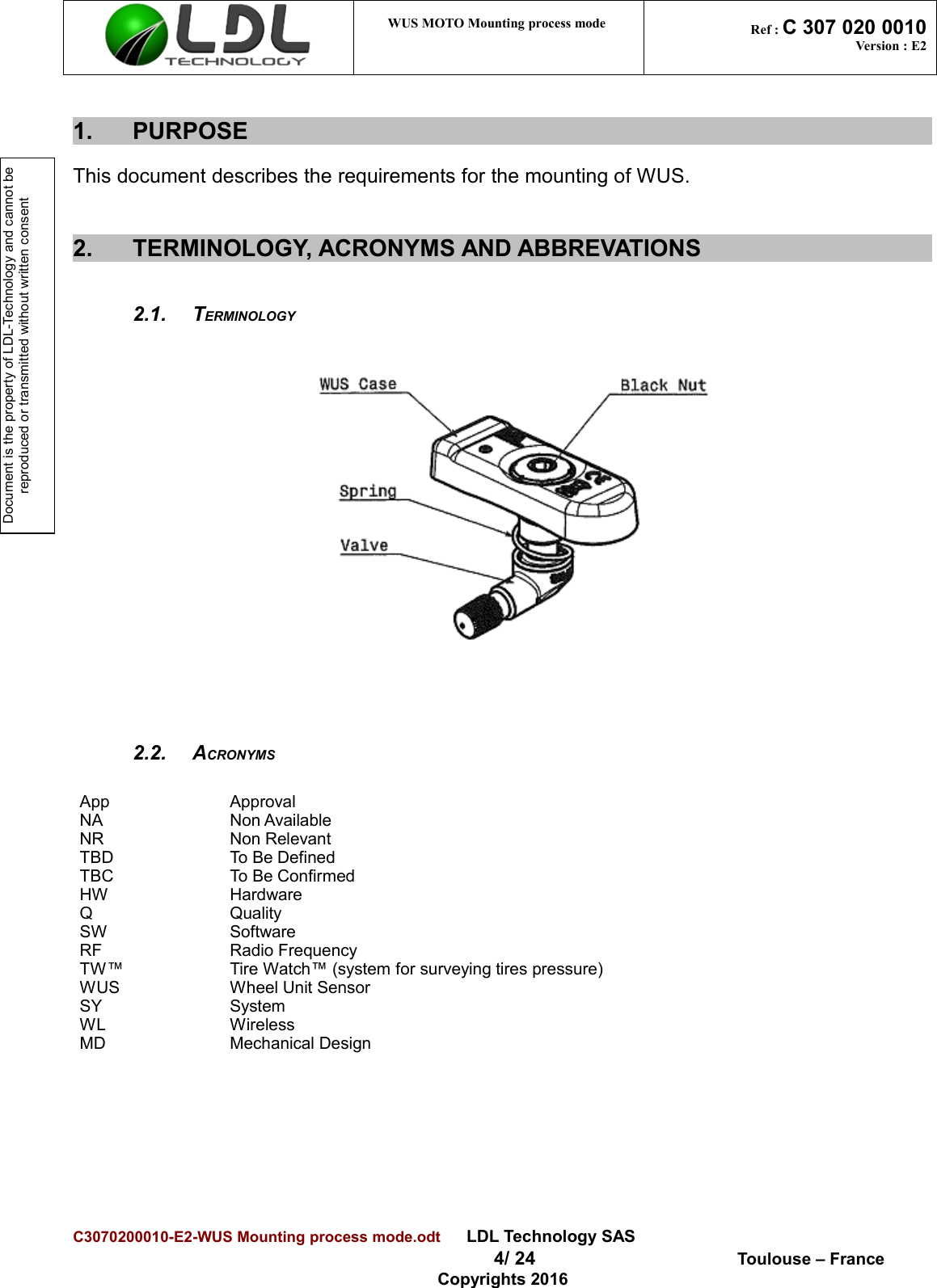
LDL Technology 12134 Tire Pressure Monitoring Transmitter User Manual WUS Mounting process mode

LDL Technology Tire Pressure Monitoring Transmitter WUS Mounting process mode

User Manual

Document is the property of LDL-Technology and cannot be reproduced or transmitted without written consent WUS MOTO Mounting process mode  Ref : C 307 020 0010Version : E2Distribution:    Internal ExternalStatus: Confidential Restricted  ExtendedTITLE: WUS MOTO Mounting process modeReference :    C 307 020 0010                                                                    Version    E2Internal ApprovalAuthor Check ApproverName and Department D. LUCE (MD) S.BAIGET (SY) P. GABAUDAN (PL)Date 06/09/16SignatureC3070200010-E2-WUS Mounting process mode.odt      LDL Technology SAS  1/ 24  Toulouse – FranceCopyrights 2016
Document is the property of LDL-Technology and cannot be reproduced or transmitted without written consentWUS MOTO Mounting process mode  Ref : C 307 020 0010Version : E2VERSIONS HISTORYVersion Update Date Chapters / Pages modifiedModification origin Author CommentsA0 13/05/08 All Creation T. Benard Initial versionA1 14/05/08 All Detailled procedure T. BenardA2 05/08/08 12 Screwing profile T. BenardA3 25/08/08 12 Screwing profile D.LuceA4 14/09/08 12 Screwing tool D.LuceA5 25/09/08 7,9,10,11,12 Screwing procedure D.LuceA6 06/01/09 Title Screwing procedure D.Luce all OEM versionB0 08/01/09 All Merge between 3080820010-A6 and S 307 020 0010-A2L.LafranchisB1 01/09/09 1 Adding C for customer document.T. BenardB2 05/10/09 All Spec for new L valve Gen2 D.LuceC0 22/10/10 6,12 Tire ease recommendation and maximum speedD.LuceD0 21/05/13 6 Recommendation on rim interfaceD.LuceE0 05/08/13 all Scheme adapted to 50° D.LuceE1 31/01/14 All Update Pictures L.LafranchisE2 06/09/16 6Warning FCC part 15/ RSSD.LuceC3070200010-E2-WUS Mounting process mode.odt      LDL Technology SAS 2/ 24  Toulouse – FranceCopyrights 2016
Document is the property of LDL-Technology and cannot be reproduced or transmitted without written consent WUS MOTO Mounting process mode  Ref : C 307 020 0010Version : E2Table des matières1.PURPOSE                                                                                                                                         ...................................................................................................................................   42.TERMINOLOGY, ACRONYMS AND ABBREVATIONS                                                                     ...............................................................   42.1.Terminology...........................................................................................................................42.2.Acronyms..............................................................................................................................43.DESCRIPTION                                                                                                                                  ............................................................................................................................   54.UTILISATION RULES                                                                                                                        ..................................................................................................................   54.1. Specifications.......................................................................................................................65.WUS MOUNTING                                                                                                                              ........................................................................................................................   65.1.Precautions during mounting operation................................................................................65.2.WUS mounting......................................................................................................................75.3.WUS screwing recommendations........................................................................................85.4.Detailed views of WUS assembly.........................................................................................95.5.Method to verify the screwing torque..................................................................................116.TIRE MOUNTING                                                                                                                            ......................................................................................................................   126.1.Precautions.........................................................................................................................126.2.Mounting.............................................................................................................................127.DISMOUNTING A TIRE EQUIPPED WITH A WUS                                                                        ..................................................................   158.WUS DISMOUNTING                                                                                                                     ...............................................................................................................   188.1.Replacing valve seal...........................................................................................................189.WUS MOUNTING – SCREWDRIVER PROCEDURE                                                                    ..............................................................   199.1.Presentation........................................................................................................................199.2.WUS holder goal.................................................................................................................2010.SCREWING STEPS                                                                                                                      ................................................................................................................   2110.1.Step 1................................................................................................................................2110.2.Step 2................................................................................................................................2210.3.Step 3................................................................................................................................24C3070200010-E2-WUS Mounting process mode.odt      LDL Technology SAS  3/ 24  Toulouse – FranceCopyrights 2016
Document is the property of LDL-Technology and cannot be reproduced or transmitted without written consent WUS MOTO Mounting process mode  Ref : C 307 020 0010Version : E21. PURPOSEThis document describes the requirements for the mounting of WUS.2. TERMINOLOGY, ACRONYMS AND ABBREVATIONS2.1. TERMINOLOGY2.2. ACRONYMSApp ApprovalNA Non AvailableNR Non RelevantTBD To Be DefinedTBC To Be ConfirmedHW HardwareQ QualitySW SoftwareRF Radio Frequency TW™ Tire Watch™ (system for surveying tires pressure)WUS Wheel Unit SensorSY SystemWL WirelessMD Mechanical DesignC3070200010-E2-WUS Mounting process mode.odt      LDL Technology SAS  4/ 24  Toulouse – FranceCopyrights 2016
Document is the property of LDL-Technology and cannot be reproduced or transmitted without written consent WUS MOTO Mounting process mode  Ref : C 307 020 0010Version : E23. DESCRIPTIONThe   wheel   unit  sensor   (WUS)   of   TIRE   WATCH  TM  system   is   a   pressure   and   temperature   sensorcomposed with: • A molded black plastic housing,• An anodized aluminium nut with BTR cavity for hexagonal key (5mm.), clipped in housing with astainless steel spring,•    An anodized aluminum valve oriented at 90°; including an EPDM seal, a short core mechanism and a cap. 4. UTILISATION RULESThe Wheel Unit Sensor can be mounted on all motorcycle rims according to the following specification : - with a minimal wide of 3 inches and with a diameter from 12 to 21 inches,- with an ETRTO compliant valve hole about 11.5mm +/- 0,2 diameter, or 8,5mm+/-0,2,- with a radial orientation of the valve hole axis- with a maximum rim thickness around the valve hole about 6 mm.- Rim Internal surface and External surface must be co planar on each side of the valve hole- No Burrs accepted  on external side of the valve hole for the seat of the seal,Valve, nut and spring seats must be plan with a sufficient diameter to accept spring, nut and valve. A seat diameter about 16.5mm +0.5 / -0 is sufficient to accept our TPMS system on spring side (internal rim side) and on valve side (external rim side)For other mounting interface (ex : hole 8,3mm or valve in spoke (BMW)) ask to LDL the specification).                                                                     C3070200010-E2-WUS Mounting process mode.odt      LDL Technology SAS  5/ 24  Toulouse – FranceCopyrights 2016Typical mountingExternal part of the rim
Document is the property of LDL-Technology and cannot be reproduced or transmitted without written consentWUS MOTO Mounting process mode  Ref : C 307 020 0010Version : E24.1.  SPECIFICATIONS   Screwing torque for valve core mechanism:  0.3 +/- 0.1 Nm.Screwing torque for valve cap:  0.2 to 0.35 Nm.Manual screwing torque for nut: 5 Nm +/- 0.5 Nm.Environmental Temperature Range:  -20°C to +60°C.Monitoring Temperature Range: -30°C to +125°CSurviving Temperature Range 1 minute :  -40°C to +150°CRelative Pressure Range Monitored:  0 to 3,5 bars.Relative Maximum pressure range non destructive: 0 to 15 barsUsed Inflating Fluid: Air or NitrogenAnti-puncture Fluid utilisation: Utilisation without any consequence.Just introduce Fluid when the valve is down, close to the ground Maximum speed of the vehicle:   350 Km/h on rim 17”******************************************************************************************************************** NOTA :5. WUS MOUNTING5.1. PRECAUTIONS DURING MOUNTING OPERATION   ¨Do NOT use WUS after a drop of more than 1 meter on a hard groundC3070200010-E2-WUS Mounting process mode.odt      LDL Technology SAS 6/ 24  Toulouse – FranceCopyrights 2016This device complies with Industry Canada's licence-exempt RSSs. Operation is subject to the following two conditions: (1) This device may not cause interference; and (2) This device must accept any interference, including interference that may cause undesired operation of the device   Le présent appareil est conforme aux CNR d'Industrie Canada applicables aux appareils radio exempts de licence. L'exploitation est autorisée aux deux conditions suivantes :   1) l'appareil ne doit pas produire de brouillage; 2) l'appareil doit accepter tout brouillage radioélectrique subi, même si le brouillage est susceptible d'en compromettre le fonctionnement.”
Document is the property of LDL-Technology and cannot be reproduced or transmitted without written consent WUS MOTO Mounting process mode  Ref : C 307 020 0010Version : E2¨Do NOT generate an electrostatic discharge higher than 6 Kilovolts by air onto the WUS, during mounting and disassembly of the WUS or at any time during utilization (avoid the use of nylon worksuit, and in general way, avoid all textile rubbing before handling WUS)¨Do NOT store the TIRE WATCH at temperatures higher than 30°C and lower than 0°C¨When removing the core from the valve, it has to be replaced by a new short core (brass without chrome forbidden) of the same type, according to V0.07.1 ETRTO core chamber specification.¨The valve cap must always be in place (except for inflating, pressure release or pressurechecks).5.2. WUS MOUNTING   ¨Check the external surface of the rim cleanness ; remove grits and other paint marks¨Orientation of the Wheel Unit Sensor on the rim :   the black housing engraved must be visibleafter mounting.¨The sensor body must be presented in front of the valve hole, inside the rim, then lay the springupon the flat surface around the valve hole.¨Shove the valve into the valve hole, the seal must face the rim.¨Push onto the WUS nut in order to bend the spring, and then start screwing the valve manuallystill the seal get in touch with the rim.¨While screwing keep the WUS in place.¨Make sure that the screwing tool stays aligned with the hexagonal cavity of the nut during thescrewing process.C3070200010-E2-WUS Mounting process mode.odt      LDL Technology SAS  7/ 24  Toulouse – FranceCopyrights 2016
Document is the property of LDL-Technology and cannot be reproduced or transmitted without written consent WUS MOTO Mounting process mode  Ref : C 307 020 0010Version : E25.3. WUS SCREWING RECOMMENDATIONS   Make sure the following recommendations are respected :Screwing speed : max of 2 turns in 1 second.¨Apply a torque of 5 Nm +/- 0,5 Nm with the good screwing speed. This is the screwing conditionof on which the specification of our WUS is based. ¨For the manual process please use a torque controlled tool.¨The valve and the nut have to be screwed on 5 complete threads (5 nut rounds) Minimum,The plastic part must slightly be able to turn around its nut after tightening; under no circumstances ithas to be in contact on the rim surface. You must be able to introduce a piece of paper between thesensor and the rim (minimum slack of 1/10 mm).Once mounted, the WUS must be distant from the rim as illustrated here under ; the distance betweenthem can reach 10mm.Optimal distance is 1mm.                             C3070200010-E2-WUS Mounting process mode.odt      LDL Technology SAS  8/ 24  Toulouse – FranceCopyrights 2016From 1/10 to10 mm
Document is the property of LDL-Technology and cannot be reproduced or transmitted without written consent WUS MOTO Mounting process mode  Ref : C 307 020 0010Version : E25.4. DETAILED VIEWS OF WUS ASSEMBLY   C3070200010-E2-WUS Mounting process mode.odt      LDL Technology SAS  9/ 24  Toulouse – FranceCopyrights 2016Step N° 1The Spring side must face the internal side of the rim.Electronic part including thespring. This part is situatedinside of the tyreRIMValve including the seal ;situated on  the  externalpart of the tireStep N°2The valve seal must face the rimvalve hole on the external side.
Document is the property of LDL-Technology and cannot be reproduced or transmitted without written consent WUS MOTO Mounting process mode  Ref : C 307 020 0010Version : E2C3070200010-E2-WUS Mounting process mode.odt      LDL Technology SAS  10/ 24  Toulouse – FranceCopyrights 2016While pushing on the nut, keep it centred on the valve hole ; then introduce the valve in the valve hole.While you are still pushing on the nut start screwing the valve manually still the seal get in touch with the rim.AVOID ANY SCREWING IF PLASTIC HOUSINGIS IN CONTACT WITH THE RIM(the introduction of a piece of paper (80gr/m²) between the rim and theplastic parts make you sure that there is no contact).Step N°4Step N°5Step N°3- Screw the nut with a allen key (5mm). Do note exceed 2 rounds per second.- Final torque 5 Nm +/- 0.5 Nm.
Document is the property of LDL-Technology and cannot be reproduced or transmitted without written consent WUS MOTO Mounting process mode  Ref : C 307 020 0010Version : E25.5. METHOD TO VERIFY THE SCREWING TORQUE   C3070200010-E2-WUS Mounting process mode.odt      LDL Technology SAS  11/ 24  Toulouse – FranceCopyrights 2016Step N°6 - Check that the external partof the valve does not meet any obstacle during rim rotation (like break system).- Check that the external seal is correctly set and that the valve is in contact with the rim.Step N°7- The flat surface of the valvemust feet the flat surface of rim valve hole.- The plastic parts must be free from rim constraints (no contact).- The plastic parts must slightly be able to turn around its nut,on approximatively +/- 5°. (no constraints on plastic parts operated by the rim sides after tightening).
Document is the property of LDL-Technology and cannot be reproduced or transmitted without written consent WUS MOTO Mounting process mode  Ref : C 307 020 0010Version : E2¨The   measurement   of   the  residual   torque   is  done  by  retightening   the   valve nut   by  a  ¼  turnmaximum in reduced speed (1/4 of a turn in 10 seconds). Therefore use a torque-controlled toolwhich is able to memorize the maximum torque. IF the torque mandatory to start the rotation ofthe nut in the measurement is equal to 4 Nm, stop the procedure, the Torque is correct.¨The retightening torque may not be smaller than 4 Nm.It is recommended to verify the screwing torque at each tire mounting.6. TIRE MOUNTING6.1. PRECAUTIONS¨Before any mounting  operation  of  the tire,  make  sure that  the  Wheel Unit  Sensor has beencorrectly mounted and tightened to the rim.¨The   tire   must   be   lubricated   so   as   to   facilitate   its   mounting.   Respect   manufacturerrecommendations.¨NO lubrication product, tire ease or any other matter may partially or completely cover the pressure measuring hole or the inflation hole of the wheel unit. In general, it is forbidden to coat the wheel unit with a soap for tire mounting¨The tire must never be allowed to put mechanical constraints onto the wheel unit sensor duringthe mounting operation; only a dynamic slide touch is acceptable, constant pressure stress isforbidden.¨Make sure that the tire does not get trapped between the rim and the wheel unit sensor duringmounting procedure.¨It’s recommended to check the screwing torque before any tire mounting.6.2. MOUNTING   ¨The bead of the tire must be engaged approximately 80° beyond the valve.¨Do not introduce a mounting tool between the valve and the point of engagement of the tire.¨Tire mounting must be done while moving away from the valve   .¨Beyond this point starts the final engagement operation, which finishes in the zone of the valve.¨During this phase, only fast sliding touch is allowed during final tire jumping onto the rim. Processto be validated by LDL Technology.C3070200010-E2-WUS Mounting process mode.odt      LDL Technology SAS  12/ 24  Toulouse – FranceCopyrights 2016
Document is the property of LDL-Technology and cannot be reproduced or transmitted without written consent WUS MOTO Mounting process mode  Ref : C 307 020 0010Version : E2For manual mounting only – standard dealer shop machineFirst sidewall :C3070200010-E2-WUS Mounting process mode.odt      LDL Technology SAS  13/ 24  Toulouse – FranceCopyrights 2016Start putting the tire onthe rim on the oppositeside of the valveThe first sidewall isnow introducedStep N°1Step N°2For clockwise tiremounting machine
Document is the property of LDL-Technology and cannot be reproduced or transmitted without written consent WUS MOTO Mounting process mode  Ref : C 307 020 0010Version : E2Second sidewall :C3070200010-E2-WUS Mounting process mode.odt      LDL Technology SAS  14/ 24  Toulouse – FranceCopyrights 2016Start introducing manuallythe second sidewallAt almost 50° far away thevalveAt the end of the mounting process, the secondsidewall end climbing on the rim when the shoeis in front of the valveStep N°3Step N°430° to 80°
Document is the property of LDL-Technology and cannot be reproduced or transmitted without written consent WUS MOTO Mounting process mode  Ref : C 307 020 0010Version : E27. DISMOUNTING A TIRE EQUIPPED WITH A WUS¨Before detaching the tire, make sure that the Wheel Unit Sensor is still correctly mounted andtightened on the rim, by checking that the valve is tightened.¨Before any introduction of tools between the tire and the rim, make sure that both sidewalls ofthe tire are completely detached from the rim.For clockwise tire mounting machineC3070200010-E2-WUS Mounting process mode.odt      LDL Technology SAS  15/ 24  Toulouse – FranceCopyrights 2016Grip the tire with the press at 50° minimum from the valveWith a tire iron, raise the first sidewall at 50° from the valve according to scheme next pageStep N°1Step N°2
Document is the property of LDL-Technology and cannot be reproduced or transmitted without written consent WUS MOTO Mounting process mode  Ref : C 307 020 0010Version : E2Scheme: Universal tire mounting and dismounting procedureC3070200010-E2-WUS Mounting process mode.odt      LDL Technology SAS  16/ 24  Toulouse – FranceCopyrights 2016Valve dans la position de départ.Valve  START  position.Outil de montage (immobile).Mounting tool (static).Jante.Rim.Environ 50°.About 50°.Sens de rotation de la roue sur l’appareilWheel spin direction on the Mounting machine.Pneu.Tire.
Document is the property of LDL-Technology and cannot be reproduced or transmitted without written consent WUS MOTO Mounting process mode  Ref : C 307 020 0010Version : E2Disassembly of the second sidewall.¨Repeat the disassembly operations of the first sidewall until the tire is completely separated fromthe rim.¨At any time the hand Tool or machine Tool must get in touch with the sensor.C3070200010-E2-WUS Mounting process mode.odt      LDL Technology SAS  17/ 24  Toulouse – FranceCopyrights 2016Slide the tool headunder the tire With a tire iron, raise the second sidewall at 50° from the valveOverviewRear ViewStep N°4Step N°5Step N°3Then make the tire turnto disengage the first sidewall
Document is the property of LDL-Technology and cannot be reproduced or transmitted without written consent WUS MOTO Mounting process mode  Ref : C 307 020 0010Version : E28. WUS DISMOUNTINGIt is MANDATORY to interchange the seal if a complete disassembly of the WUS is done (if youchange  the  rim  for   example),  all  unscrewing  action  on  the  nut   is equivalent  to   a  completedisassembly.   It’s   RECOMMANDED   to   check   the   screwing   torque   at   each   time   the   tire   isdismounted8.1. REPLACING VALVE SEAL   For the used valve seal dismounting, use a PLASTIC TOOL to disengage the seal from its case (in order to avoid damaging the valve).NEW VALVE SEAL MOUNTING¨Do not use lubricant, solvent, grease or oil.¨Check that the valve can be used again.¨C3070200010-E2-WUS Mounting process mode.odt      LDL Technology SAS  18/ 24  Toulouse – FranceCopyrights 2016Disengage the sealfrom its caseSlide the seal alongthe valve bodyIT IS MANDATORY TO CHANGE THEVALVE IF THERE IS ANY SCRATCHOR HIT IN THIS AREACheck that the seal isin its lower positionShove the seal into the valvePresent the seal in thisway, flat surface orientedto the valve capTHREADINGRemove the usedseal
Document is the property of LDL-Technology and cannot be reproduced or transmitted without written consent WUS MOTO Mounting process mode  Ref : C 307 020 0010Version : E29. WUS MOUNTING – SCREWDRIVER PROCEDURE9.1. PRESENTATIONC3070200010-E2-WUS Mounting process mode.odt      LDL Technology SAS  19/ 24  Toulouse – FranceCopyrights 2016WUS HOLDERWUS HOLDER FIXED ONTO SCREWDRIVERScrewdriver (here LUM12 HRX8-50 from Atlas Copco reference: 8431028025)Screwdriver clutchHexagonal5mm wrench
Document is the property of LDL-Technology and cannot be reproduced or transmitted without written consent WUS MOTO Mounting process mode  Ref : C 307 020 0010Version : E29.2. WUS HOLDER GOALFor an automatic screwing, LDL recommend to use a WUS holder fixed onto the screwdriverwhich pushes the case down and lock the case in rotation. C3070200010-E2-WUS Mounting process mode.odt      LDL Technology SAS  20/ 24  Toulouse – FranceCopyrights 2016PushAnti rotationshapesWUS casedisplacement
Document is the property of LDL-Technology and cannot be reproduced or transmitted without written consent WUS MOTO Mounting process mode  Ref : C 307 020 0010Version : E210. SCREWING STEPS 10.1. STEP 1Introduce the valveStart the screwing by hand till get contact between seal and rim external side.C3070200010-E2-WUS Mounting process mode.odt      LDL Technology SAS  21/ 24  Toulouse – FranceCopyrights 2016Autorized area to hold the valve by hand
Document is the property of LDL-Technology and cannot be reproduced or transmitted without written consent WUS MOTO Mounting process mode  Ref : C 307 020 0010Version : E210.2. STEP 2Apply automatic screwdriver on the top housing till rise the introduction of the hexagonal 5mm wrench into the nut and lock in rotation the case with the WUS Holder (PTFE part mounted ontothe screw driver). Just maintain the valve with hand by its nose.C3070200010-E2-WUS Mounting process mode.odt      LDL Technology SAS  22/ 24  Toulouse – FranceCopyrights 2016Push
Document is the property of LDL-Technology and cannot be reproduced or transmitted without written consent WUS MOTO Mounting process mode  Ref : C 307 020 0010Version : E2C3070200010-E2-WUS Mounting process mode.odt      LDL Technology SAS  23/ 24  Toulouse – FranceCopyrights 2016Push
Document is the property of LDL-Technology and cannot be reproduced or transmitted without written consent WUS MOTO Mounting process mode  Ref : C 307 020 0010Version : E2Details on WUS case displacement:For a better understanding WUS holder is represented with a partial cut (orange area)Now the screwdriver clutch is on the nut and the WUS holder has pushed down the WUS case. There is a gap between the nut head and the WUS case (green arrow on scheme) so we can start screwing without the nut touching the WUS case and damaging the WUS anti rotation embossed shapes.During screwing the nut must be pressed onto the rim, so it is the nut which achieves the coaxiality of the assembly in the valve hole and not the valve seal. 10.3. STEP 3In case of L-Valve rotation under screwing action, hold the valve during the screwing process with a PTFE spanner to avoid marking and scratch onto the valve anodization.LDL recommend to screw according the profile explained below :Screw the valve by hand till get contact between valve seal and external rim side (around5 complete turns). Screwing by hand on at least 1 turn is also accepted for industrial production.Screw the nut with a torque gun at constant speed :No minimum, 50 rpm recommended , 100 rpm maximum , do not exceed 120rpm MAX FINAL TORQUE: 5 Nm ± 0.5 NmC3070200010-E2-WUS Mounting process mode.odt      LDL Technology SAS  24/ 24  Toulouse – FranceCopyrights 2016Torque gun speed , in RPM110 120050 100Screwing toolAtlas Copco referenceLUM12 HRX8-50 LUM12 HRX8-110

Navigation menu