LDL Technology 12134 Tire Pressure Monitoring Transmitter User Manual WUS Mounting process mode
LDL Technology Tire Pressure Monitoring Transmitter WUS Mounting process mode
User Manual
Document is the property of LDL-Technology and cannot be
reproduced or transmitted without written consent
WUS MOTO Mounting process mode Ref : C 307 020 0010
Version : E2
Distribution: Internal External
Status: Confidential Restricted Extended
TITLE: WUS MOTO Mounting process mode
Reference : C 307 020 0010 Version E2
Internal Approval
Author Check Approver
Name and
Department D. LUCE (MD) S.BAIGET (SY) P. GABAUDAN (PL)
Date 06/09/16
Signature
C3070200010-E2-WUS Mounting process mode.odt LDL Technology SAS
1/ 24 Toulouse – France
Copyrights 2016

Document is the property of LDL-Technology and cannot be
reproduced or transmitted without written consent
WUS MOTO Mounting process mode Ref : C 307 020 0010
Version : E2
VERSIONS HISTORY
Version Update
Date
Chapters /
Pages
modified
Modification origin Author Comments
A0 13/05/08 All Creation T. Benard Initial version
A1 14/05/08 All Detailled procedure T. Benard
A2 05/08/08 12 Screwing profile T. Benard
A3 25/08/08 12 Screwing profile D.Luce
A4 14/09/08 12 Screwing tool D.Luce
A5 25/09/08 7,9,10,11,12 Screwing procedure D.Luce
A6 06/01/09 Title Screwing procedure D.Luce all OEM version
B0 08/01/09 All Merge between
3080820010-A6 and S 307
020 0010-A2
L.Lafranchis
B1 01/09/09 1 Adding C for customer
document.
T. Benard
B2 05/10/09 All Spec for new L valve Gen2 D.Luce
C0 22/10/10 6,12 Tire ease recommendation
and maximum speed
D.Luce
D0 21/05/13 6 Recommendation on rim
interface
D.Luce
E0 05/08/13 all Scheme adapted to 50° D.Luce
E1 31/01/14 All Update Pictures L.Lafranchis
E2 06/09/16 6
Warning FCC part 15/ RSS
D.Luce
C3070200010-E2-WUS Mounting process mode.odt LDL Technology SAS
2/ 24 Toulouse – France
Copyrights 2016
Document is the property of LDL-Technology and cannot be
reproduced or transmitted without written consent
WUS MOTO Mounting process mode Ref : C 307 020 0010
Version : E2
Table des matières
1.PURPOSE ................................................................................................................................... 4
2.TERMINOLOGY, ACRONYMS AND ABBREVATIONS ............................................................... 4
2.1.Terminology...........................................................................................................................4
2.2.Acronyms..............................................................................................................................4
3.DESCRIPTION ............................................................................................................................ 5
4.UTILISATION RULES .................................................................................................................. 5
4.1. Specifications.......................................................................................................................6
5.WUS MOUNTING ........................................................................................................................ 6
5.1.Precautions during mounting operation................................................................................6
5.2.WUS mounting......................................................................................................................7
5.3.WUS screwing recommendations........................................................................................8
5.4.Detailed views of WUS assembly.........................................................................................9
5.5.Method to verify the screwing torque..................................................................................11
6.TIRE MOUNTING ...................................................................................................................... 12
6.1.Precautions.........................................................................................................................12
6.2.Mounting.............................................................................................................................12
7.DISMOUNTING A TIRE EQUIPPED WITH A WUS .................................................................. 15
8.WUS DISMOUNTING ............................................................................................................... 18
8.1.Replacing valve seal...........................................................................................................18
9.WUS MOUNTING – SCREWDRIVER PROCEDURE .............................................................. 19
9.1.Presentation........................................................................................................................19
9.2.WUS holder goal.................................................................................................................20
10.SCREWING STEPS ................................................................................................................ 21
10.1.Step 1................................................................................................................................21
10.2.Step 2................................................................................................................................22
10.3.Step 3................................................................................................................................24
C3070200010-E2-WUS Mounting process mode.odt LDL Technology SAS
3/ 24 Toulouse – France
Copyrights 2016
Document is the property of LDL-Technology and cannot be
reproduced or transmitted without written consent
WUS MOTO Mounting process mode Ref : C 307 020 0010
Version : E2
1. PURPOSE
This document describes the requirements for the mounting of WUS.
2. TERMINOLOGY, ACRONYMS AND ABBREVATIONS
2.1. TERMINOLOGY
2.2. ACRONYMS
App Approval
NA Non Available
NR Non Relevant
TBD To Be Defined
TBC To Be Confirmed
HW Hardware
Q Quality
SW Software
RF Radio Frequency
TW™ Tire Watch™ (system for surveying tires pressure)
WUS Wheel Unit Sensor
SY System
WL Wireless
MD Mechanical Design
C3070200010-E2-WUS Mounting process mode.odt LDL Technology SAS
4/ 24 Toulouse – France
Copyrights 2016
Document is the property of LDL-Technology and cannot be
reproduced or transmitted without written consent
WUS MOTO Mounting process mode Ref : C 307 020 0010
Version : E2
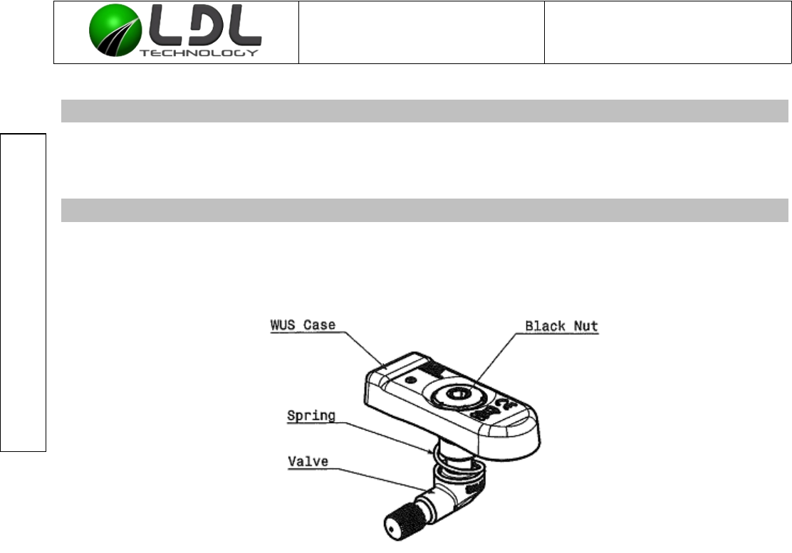
3. DESCRIPTION
The wheel unit sensor (WUS) of TIRE WATCH TM system is a pressure and temperature sensor
composed with:
• A molded black plastic housing,
• An anodized aluminium nut with BTR cavity for hexagonal key (5mm.), clipped in housing with a
stainless steel spring,
• An anodized aluminum valve oriented at 90°; including an EPDM seal, a short core mechanism
and a cap.
4. UTILISATION RULES
The Wheel Unit Sensor can be mounted on all motorcycle rims according to the following specification :
- with a minimal wide of 3 inches and with a diameter from 12 to 21 inches,
- with an ETRTO compliant valve hole about 11.5mm +/- 0,2 diameter, or 8,5mm+/-0,2,
- with a radial orientation of the valve hole axis
- with a maximum rim thickness around the valve hole about 6 mm.
- Rim Internal surface and External surface must be co planar on each side of the valve hole
- No Burrs accepted on external side of the valve hole for the seat of the seal,
Valve, nut and spring seats must be plan with a sufficient diameter to accept spring, nut and valve.
A seat diameter about 16.5mm +0.5 / -0 is sufficient to accept our TPMS system on spring side
(internal rim side) and on valve side (external rim side)
For other mounting interface (ex : hole 8,3mm or valve in spoke (BMW)) ask to LDL the specification).
C3070200010-E2-WUS Mounting process mode.odt LDL Technology SAS
5/ 24 Toulouse – France
Copyrights 2016
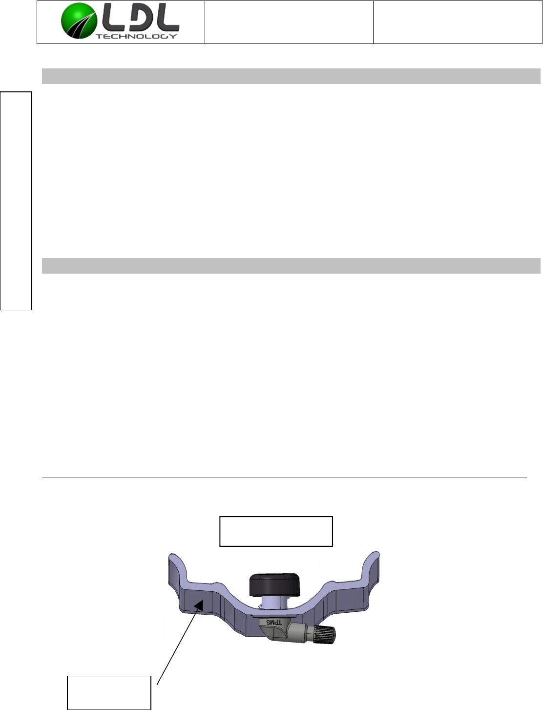
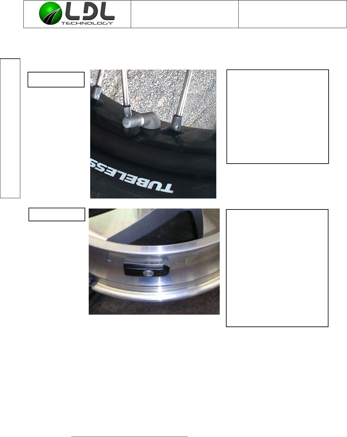
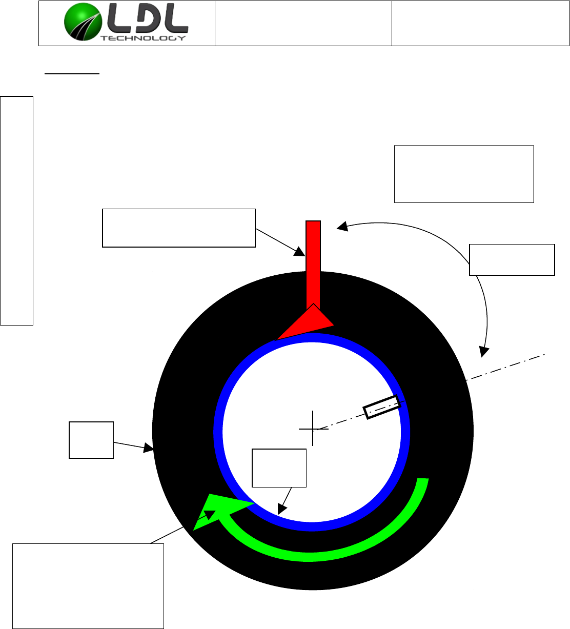
Typical mounting
External part
of the rim
Document is the property of LDL-Technology and cannot be
reproduced or transmitted without written consent
WUS MOTO Mounting process mode Ref : C 307 020 0010
Version : E2
4.1. SPECIFICATIONS
Screwing torque for valve core mechanism: 0.3 +/- 0.1 Nm.
Screwing torque for valve cap: 0.2 to 0.35 Nm.
Manual screwing torque for nut: 5 Nm +/- 0.5 Nm.
Environmental Temperature Range: -20°C to +60°C.
Monitoring Temperature Range: -30°C to +125°C
Surviving Temperature Range 1 minute : -40°C to +150°C
Relative Pressure Range Monitored: 0 to 3,5 bars.
Relative Maximum pressure range non destructive: 0 to 15 bars
Used Inflating Fluid: Air or Nitrogen
Anti-puncture Fluid utilisation: Utilisation without any consequence.
Just introduce Fluid when the valve
is down, close to the ground
Maximum speed of the vehicle: 350 Km/h on rim 17”
********************************************************************************************************************
NOTA :
5. WUS MOUNTING
5.1. PRECAUTIONS DURING MOUNTING OPERATION
¨Do NOT use WUS after a drop of more than 1 meter on a hard ground
C3070200010-E2-WUS Mounting process mode.odt LDL Technology SAS
6/ 24 Toulouse – France
Copyrights 2016
This device complies with Industry Canada's licence-exempt RSSs. Operation is subject to the following two conditions:
(1) This device may not cause interference; and (2) This device must accept any interference, including interference that may cause
undesired operation of the device
Le présent appareil est conforme aux CNR d'Industrie Canada applicables aux appareils radio exempts de licence. L'exploitation est
autorisée aux deux conditions suivantes :
1) l'appareil ne doit pas produire de brouillage; 2) l'appareil doit accepter tout brouillage radioélectrique subi, même si le brouillage est
susceptible d'en compromettre le fonctionnement.”

Document is the property of LDL-Technology and cannot be
reproduced or transmitted without written consent
WUS MOTO Mounting process mode Ref : C 307 020 0010
Version : E2
¨Do NOT generate an electrostatic discharge higher than 6 Kilovolts by air onto the WUS, during
mounting and disassembly of the WUS or at any time during utilization (avoid the use of nylon
worksuit, and in general way, avoid all textile rubbing before handling WUS)
¨Do NOT store the TIRE WATCH at temperatures higher than 30°C and lower than 0°C
¨When removing the core from the valve, it has to be replaced by a new short core (brass without
chrome forbidden) of the same type, according to V0.07.1 ETRTO core chamber specification.
¨The valve cap must always be in place (except for inflating, pressure release or pressure
checks).
5.2. WUS MOUNTING
¨Check the external surface of the rim cleanness ; remove grits and other paint marks
¨Orientation of the Wheel Unit Sensor on the rim : the black housing engraved must be visible
after mounting.
¨The sensor body must be presented in front of the valve hole, inside the rim, then lay the spring
upon the flat surface around the valve hole.
¨Shove the valve into the valve hole, the seal must face the rim.
¨Push onto the WUS nut in order to bend the spring, and then start screwing the valve manually
still the seal get in touch with the rim.
¨While screwing keep the WUS in place.
¨Make sure that the screwing tool stays aligned with the hexagonal cavity of the nut during the
screwing process.
C3070200010-E2-WUS Mounting process mode.odt LDL Technology SAS
7/ 24 Toulouse – France
Copyrights 2016
Document is the property of LDL-Technology and cannot be
reproduced or transmitted without written consent
WUS MOTO Mounting process mode Ref : C 307 020 0010
Version : E2
5.3. WUS SCREWING RECOMMENDATIONS
Make sure the following recommendations are respected :
Screwing speed : max of 2 turns in 1 second.
¨Apply a torque of 5 Nm +/- 0,5 Nm with the good screwing speed. This is the screwing condition
of on which the specification of our WUS is based.
¨For the manual process please use a torque controlled tool.
¨The valve and the nut have to be screwed on 5 complete threads (5 nut rounds) Minimum,
The plastic part must slightly be able to turn around its nut after tightening; under no circumstances it
has to be in contact on the rim surface. You must be able to introduce a piece of paper between the
sensor and the rim (minimum slack of 1/10 mm).
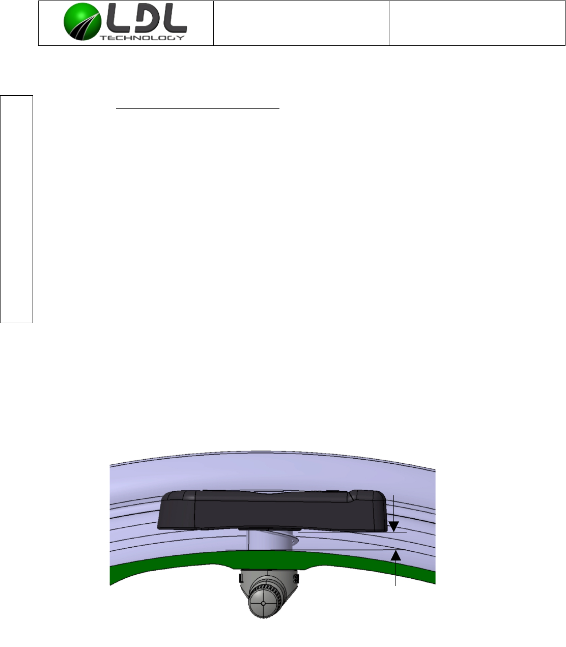
Once mounted, the WUS must be distant from the rim as illustrated here under ; the distance between
them can reach 10mm.
Optimal distance is 1mm.
C3070200010-E2-WUS Mounting process mode.odt LDL Technology SAS
8/ 24 Toulouse – France
Copyrights 2016
From 1/10 to
10 mm
Document is the property of LDL-Technology and cannot be
reproduced or transmitted without written consent
WUS MOTO Mounting process mode Ref : C 307 020 0010
Version : E2
5.4. DETAILED VIEWS OF WUS ASSEMBLY
C3070200010-E2-WUS Mounting process mode.odt LDL Technology SAS
9/ 24 Toulouse – France
Copyrights 2016
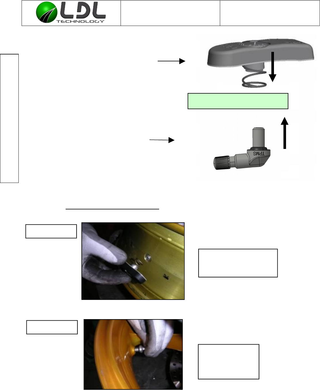
Step N° 1
The Spring side must
face the internal side of
the rim.
Electronic part including the
spring. This part is situated
inside of the tyre
RIM
Valve including the seal ;
situated on the external
part of the tire
Step N°2
The valve seal
must face the rim
valve hole on the
external side.
Document is the property of LDL-Technology and cannot be
reproduced or transmitted without written consent
WUS MOTO Mounting process mode Ref : C 307 020 0010
Version : E2
C3070200010-E2-WUS Mounting process mode.odt LDL Technology SAS
10/ 24 Toulouse – France
Copyrights 2016
While pushing on the
nut, keep it centred on
the valve hole ; then
introduce the valve in
the valve hole.
While you are still pushing
on the nut start screwing the
valve manually still the seal
get in touch with the rim.
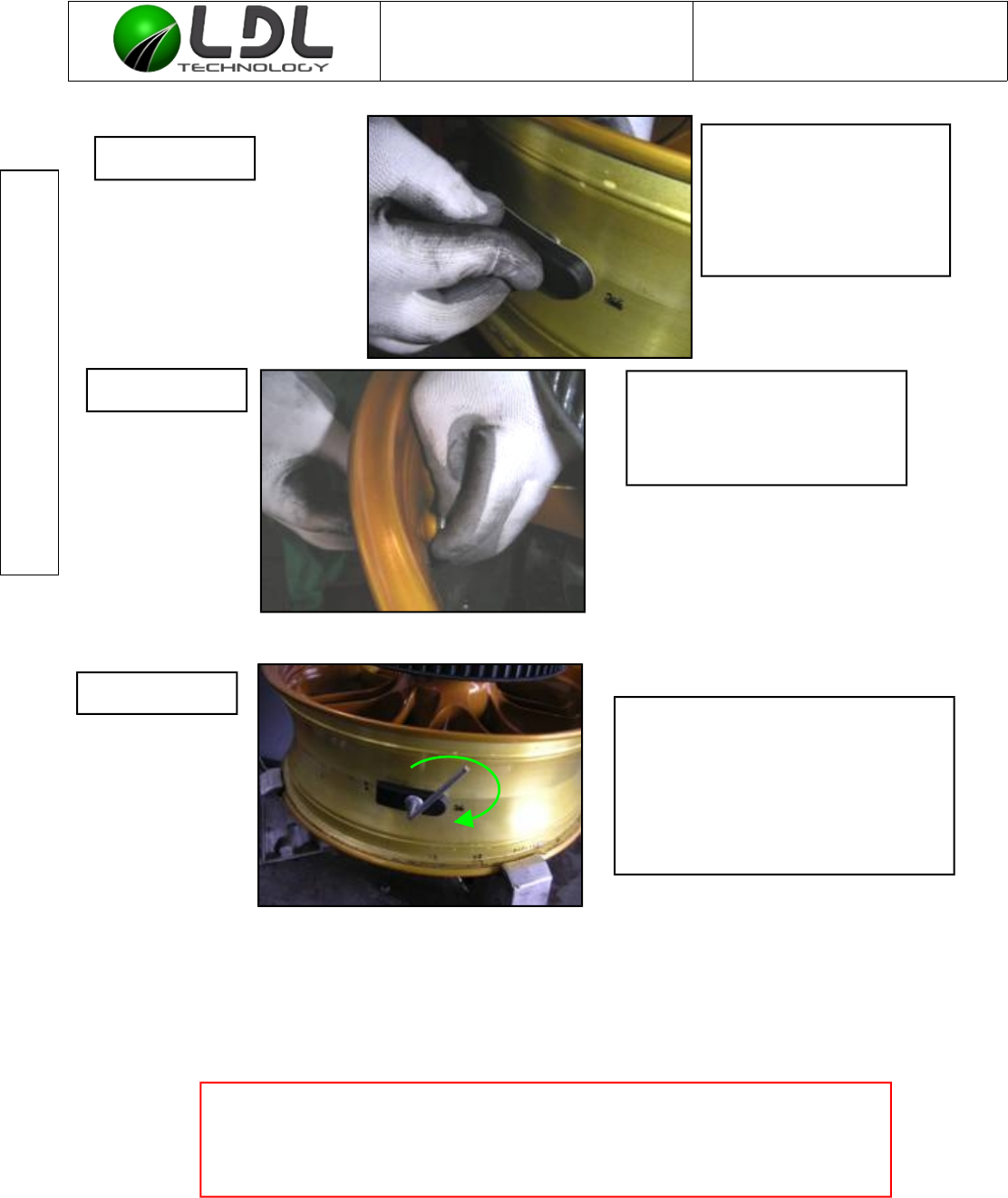
AVOID ANY SCREWING IF PLASTIC HOUSING
IS IN CONTACT WITH THE RIM
(the introduction of a piece of paper (80gr/m²) between the rim and the
plastic parts make you sure that there is no contact).
Step N°4
Step N°5
Step N°3
- Screw the nut with a allen key
(5mm). Do note exceed 2 rounds
per second.
- Final torque 5 Nm +/- 0.5 Nm.
Document is the property of LDL-Technology and cannot be
reproduced or transmitted without written consent
WUS MOTO Mounting process mode Ref : C 307 020 0010
Version : E2
5.5. METHOD TO VERIFY THE SCREWING TORQUE
C3070200010-E2-WUS Mounting process mode.odt LDL Technology SAS
11/ 24 Toulouse – France
Copyrights 2016
Step N°6 - Check that the external part
of the valve does not meet
any obstacle during rim
rotation (like break system).
- Check that the external
seal is correctly set and that
the valve is in contact with
the rim.
Step N°7
- The flat surface of the valve
must feet the flat surface of
rim valve hole.
- The plastic parts must be
free from rim constraints (no
contact).
- The plastic parts must
slightly be able to turn
around its nut,on
approximatively +/- 5°. (no
constraints on plastic parts
operated by the rim sides
after tightening).

Document is the property of LDL-Technology and cannot be
reproduced or transmitted without written consent
WUS MOTO Mounting process mode Ref : C 307 020 0010
Version : E2
¨The measurement of the residual torque is done by retightening the valve nut by a ¼ turn
maximum in reduced speed (1/4 of a turn in 10 seconds). Therefore use a torque-controlled tool
which is able to memorize the maximum torque. IF the torque mandatory to start the rotation of
the nut in the measurement is equal to 4 Nm, stop the procedure, the Torque is correct.
¨The retightening torque may not be smaller than 4 Nm.
It is recommended to verify the screwing torque at each tire mounting.
6. TIRE MOUNTING
6.1. PRECAUTIONS
¨Before any mounting operation of the tire, make sure that the Wheel Unit Sensor has been
correctly mounted and tightened to the rim.
¨The tire must be lubricated so as to facilitate its mounting. Respect manufacturer
recommendations.
¨NO lubrication product, tire ease or any other matter may partially or completely cover the
pressure measuring hole or the inflation hole of the wheel unit. In general, it is forbidden to
coat the wheel unit with a soap for tire mounting
¨The tire must never be allowed to put mechanical constraints onto the wheel unit sensor during
the mounting operation; only a dynamic slide touch is acceptable, constant pressure stress is
forbidden.
¨Make sure that the tire does not get trapped between the rim and the wheel unit sensor during
mounting procedure.
¨It’s recommended to check the screwing torque before any tire mounting.
6.2. MOUNTING
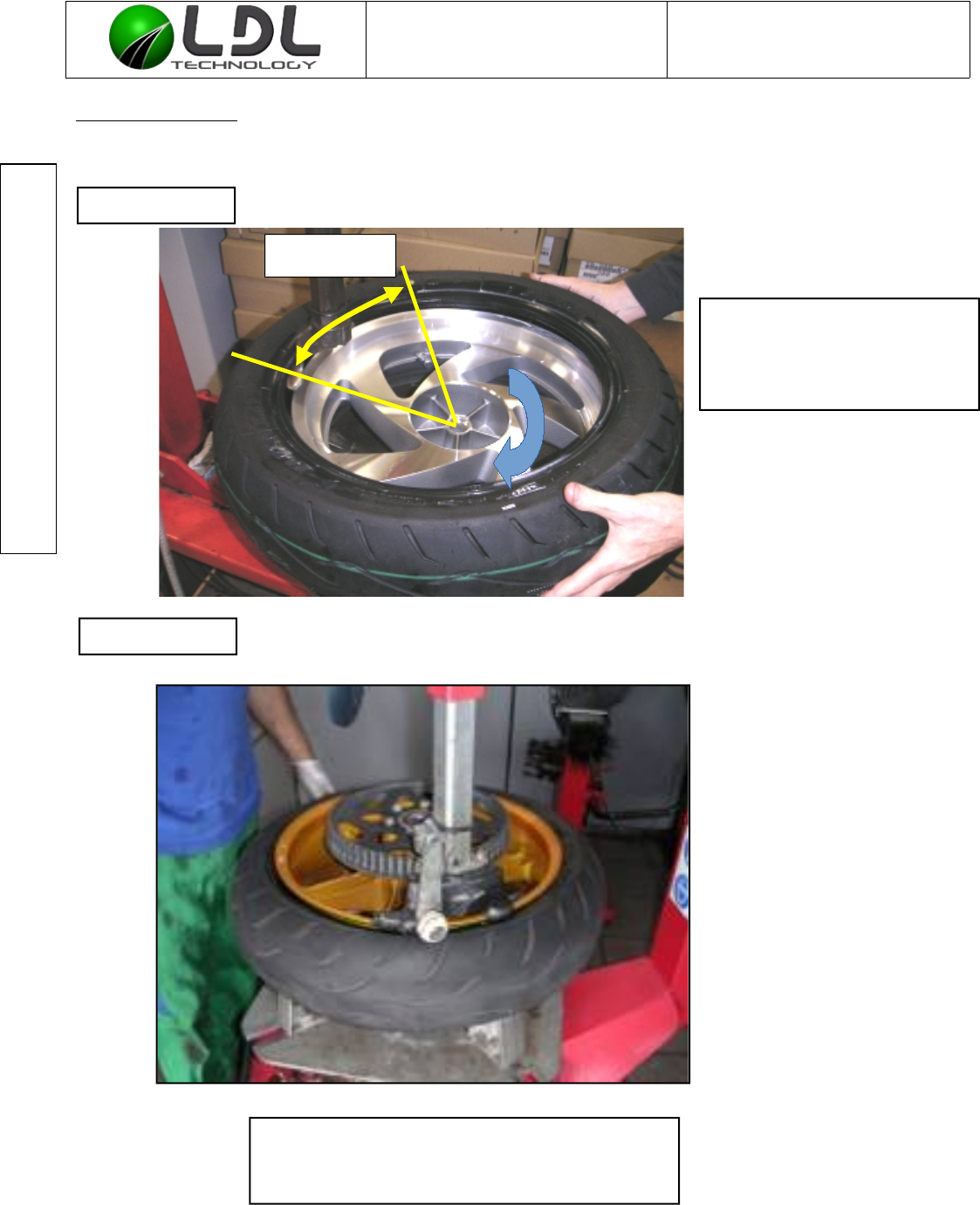
¨The bead of the tire must be engaged approximately 80° beyond the valve.
¨Do not introduce a mounting tool between the valve and the point of engagement of the tire.
¨Tire mounting must be done while moving away from the valve .
¨Beyond this point starts the final engagement operation, which finishes in the zone of the valve.
¨During this phase, only fast sliding touch is allowed during final tire jumping onto the rim. Process
to be validated by LDL Technology.
C3070200010-E2-WUS Mounting process mode.odt LDL Technology SAS
12/ 24 Toulouse – France
Copyrights 2016
Document is the property of LDL-Technology and cannot be
reproduced or transmitted without written consent
WUS MOTO Mounting process mode Ref : C 307 020 0010
Version : E2
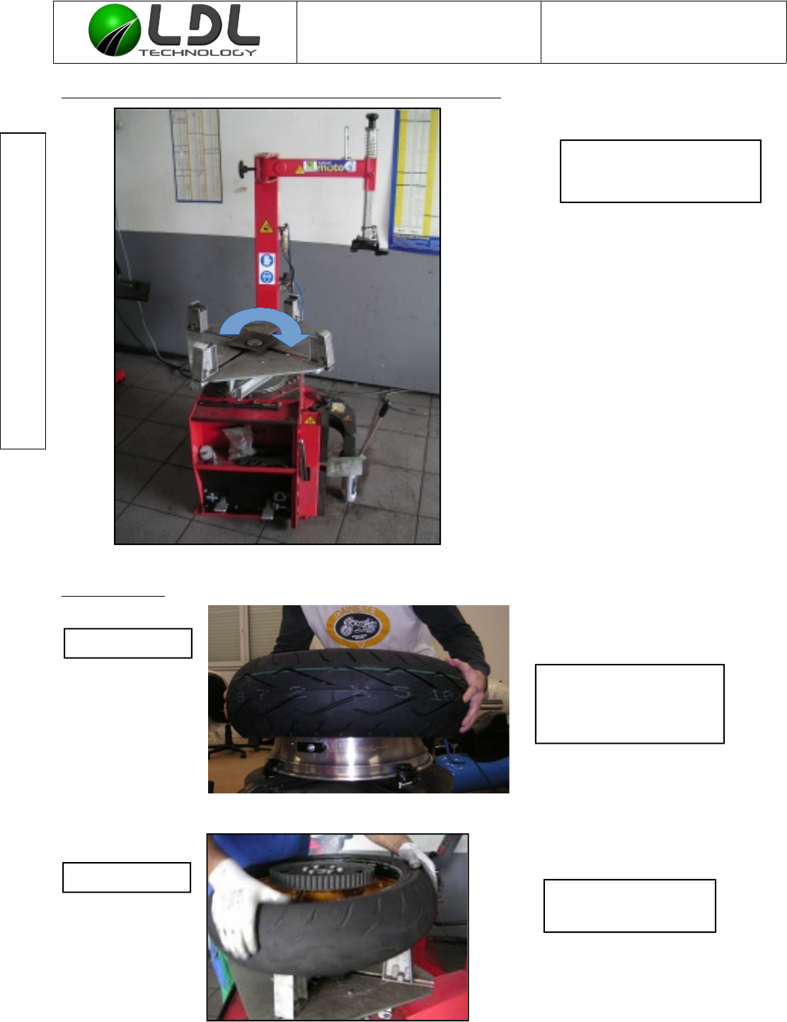
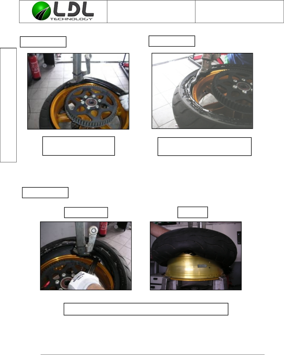
For manual mounting only – standard dealer shop machine
First sidewall :
C3070200010-E2-WUS Mounting process mode.odt LDL Technology SAS
13/ 24 Toulouse – France
Copyrights 2016
Start putting the tire on
the rim on the opposite
side of the valve
The first sidewall is
now introduced
Step N°1
Step N°2
For clockwise tire
mounting machine
Document is the property of LDL-Technology and cannot be
reproduced or transmitted without written consent
WUS MOTO Mounting process mode Ref : C 307 020 0010
Version : E2
Second sidewall :
C3070200010-E2-WUS Mounting process mode.odt LDL Technology SAS
14/ 24 Toulouse – France
Copyrights 2016
Start introducing manually
the second sidewall
At almost 50° far away the
valve
At the end of the mounting process, the second
sidewall end climbing on the rim when the shoe
is in front of the valve
Step N°3
Step N°4
30° to 80°
Document is the property of LDL-Technology and cannot be
reproduced or transmitted without written consent
WUS MOTO Mounting process mode Ref : C 307 020 0010
Version : E2
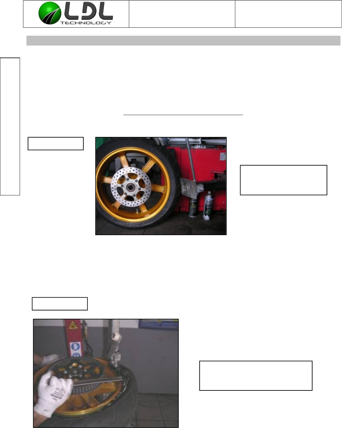
7. DISMOUNTING A TIRE EQUIPPED WITH A WUS
¨Before detaching the tire, make sure that the Wheel Unit Sensor is still correctly mounted and
tightened on the rim, by checking that the valve is tightened.
¨Before any introduction of tools between the tire and the rim, make sure that both sidewalls of
the tire are completely detached from the rim.
For clockwise tire mounting machine
C3070200010-E2-WUS Mounting process mode.odt LDL Technology SAS
15/ 24 Toulouse – France
Copyrights 2016
Grip the tire with the press
at 50° minimum from the
valve
With a tire iron, raise the first
sidewall at 50° from the valve
according to scheme next page
Step N°1
Step N°2
Document is the property of LDL-Technology and cannot be
reproduced or transmitted without written consent
WUS MOTO Mounting process mode Ref : C 307 020 0010
Version : E2
Scheme: Universal tire mounting and dismounting procedure
C3070200010-E2-WUS Mounting process mode.odt LDL Technology SAS
16/ 24 Toulouse – France
Copyrights 2016
Valve dans la position de
départ.
Valve START position.
Outil de montage (immobile).
Mounting tool (static).
Jante.
Rim.
Environ 50°.
About 50°.
Sens de rotation de la roue
sur l’appareil
Wheel spin direction on the
Mounting machine.
Pneu.
Tire.
Document is the property of LDL-Technology and cannot be
reproduced or transmitted without written consent
WUS MOTO Mounting process mode Ref : C 307 020 0010
Version : E2
Disassembly of the second sidewall.
¨Repeat the disassembly operations of the first sidewall until the tire is completely separated from
the rim.
¨At any time the hand Tool or machine Tool must get in touch with the sensor.
C3070200010-E2-WUS Mounting process mode.odt LDL Technology SAS
17/ 24 Toulouse – France
Copyrights 2016
Slide the tool head
under the tire
With a tire iron, raise the second sidewall at 50° from the valve
Overview
Rear View
Step N°4
Step N°5
Step N°3
Then make the tire turn
to disengage the first sidewall
Document is the property of LDL-Technology and cannot be
reproduced or transmitted without written consent
WUS MOTO Mounting process mode Ref : C 307 020 0010
Version : E2
8. WUS DISMOUNTING
It is MANDATORY to interchange the seal if a complete disassembly of the WUS is done (if you
change the rim for example), all unscrewing action on the nut is equivalent to a complete
disassembly. It’s RECOMMANDED to check the screwing torque at each time the tire is
dismounted
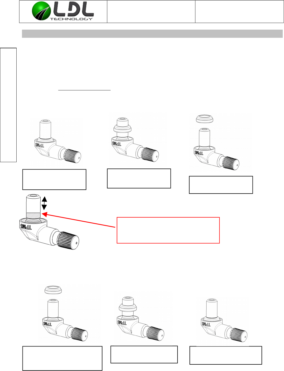
8.1. REPLACING VALVE SEAL
For the used valve seal dismounting, use a PLASTIC TOOL to disengage the seal from its case (in order to
avoid damaging the valve).
NEW VALVE SEAL MOUNTING
¨Do not use lubricant, solvent, grease or oil.
¨Check that the valve can be used again.
¨
C3070200010-E2-WUS Mounting process mode.odt LDL Technology SAS
18/ 24 Toulouse – France
Copyrights 2016
Disengage the seal
from its case
Slide the seal along
the valve body
IT IS MANDATORY TO CHANGE THE
VALVE IF THERE IS ANY SCRATCH
OR HIT IN THIS AREA
Check that the seal is
in its lower position
Shove the seal
into the valve
Present the seal in this
way, flat surface oriented
to the valve cap
THREADING
Remove the used
seal
Document is the property of LDL-Technology and cannot be
reproduced or transmitted without written consent
WUS MOTO Mounting process mode Ref : C 307 020 0010
Version : E2
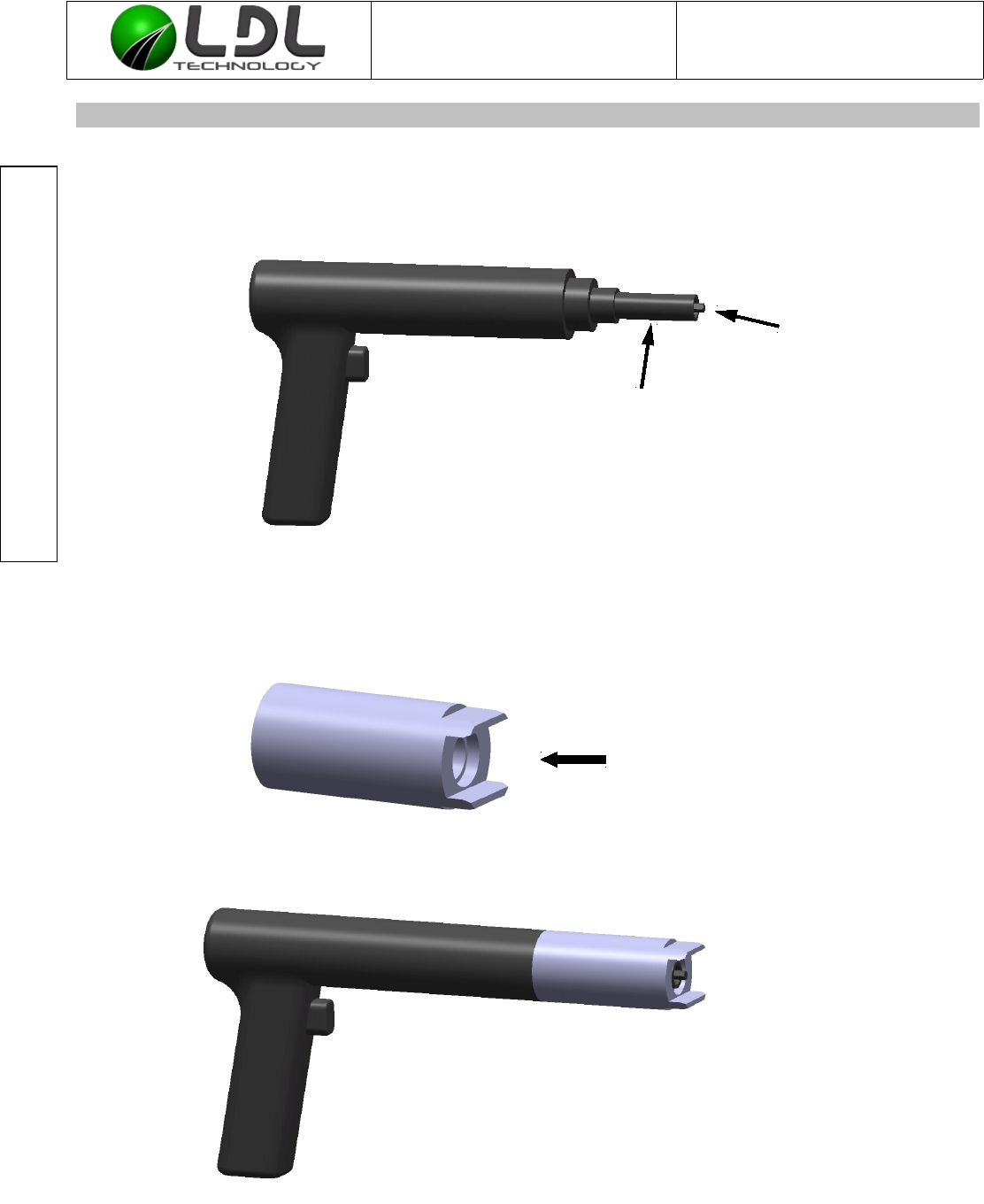
9. WUS MOUNTING – SCREWDRIVER PROCEDURE
9.1. PRESENTATION
C3070200010-E2-WUS Mounting process mode.odt LDL Technology SAS
19/ 24 Toulouse – France
Copyrights 2016
WUS HOLDER
WUS HOLDER FIXED ONTO SCREWDRIVER
Screwdriver (here LUM12 HRX8-50 from
Atlas Copco reference: 8431028025)
Screwdriver clutch
Hexagonal
5mm wrench
Document is the property of LDL-Technology and cannot be
reproduced or transmitted without written consent
WUS MOTO Mounting process mode Ref : C 307 020 0010
Version : E2
9.2. WUS HOLDER GOAL
For an automatic screwing, LDL recommend to use a WUS holder fixed onto the screwdriver
which pushes the case down and lock the case in rotation.
C3070200010-E2-WUS Mounting process mode.odt LDL Technology SAS
20/ 24 Toulouse – France
Copyrights 2016
Push
Anti rotation
shapes
WUS case
displacement
Document is the property of LDL-Technology and cannot be
reproduced or transmitted without written consent
WUS MOTO Mounting process mode Ref : C 307 020 0010
Version : E2
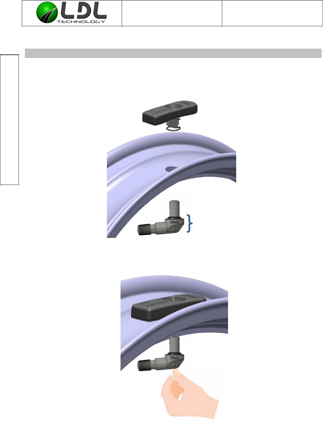
10. SCREWING STEPS
10.1. STEP 1
Introduce the valve
Start the screwing by hand till get contact between seal and rim external side.
C3070200010-E2-WUS Mounting process mode.odt LDL Technology SAS
21/ 24 Toulouse – France
Copyrights 2016
Autorized area to hold the
valve by hand
Document is the property of LDL-Technology and cannot be
reproduced or transmitted without written consent
WUS MOTO Mounting process mode Ref : C 307 020 0010
Version : E2
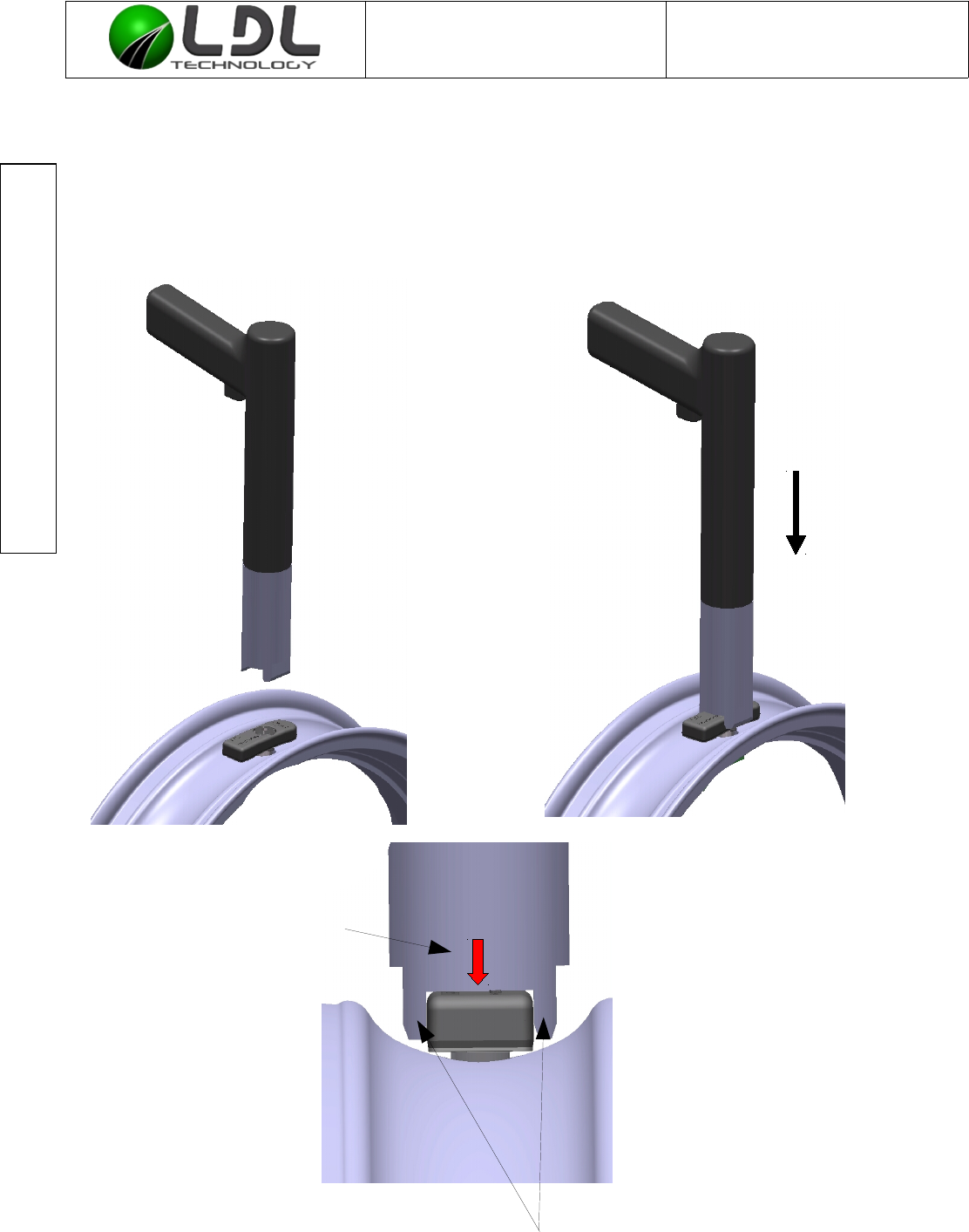
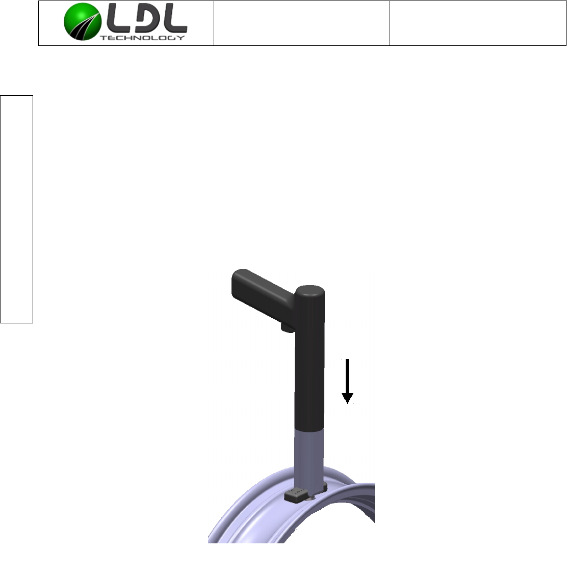
10.2. STEP 2
Apply automatic screwdriver on the top housing till rise the introduction of the hexagonal 5mm
wrench into the nut and lock in rotation the case with the WUS Holder (PTFE part mounted onto
the screw driver). Just maintain the valve with hand by its nose.
C3070200010-E2-WUS Mounting process mode.odt LDL Technology SAS
22/ 24 Toulouse – France
Copyrights 2016
Push

Document is the property of LDL-Technology and cannot be
reproduced or transmitted without written consent
WUS MOTO Mounting process mode Ref : C 307 020 0010
Version : E2
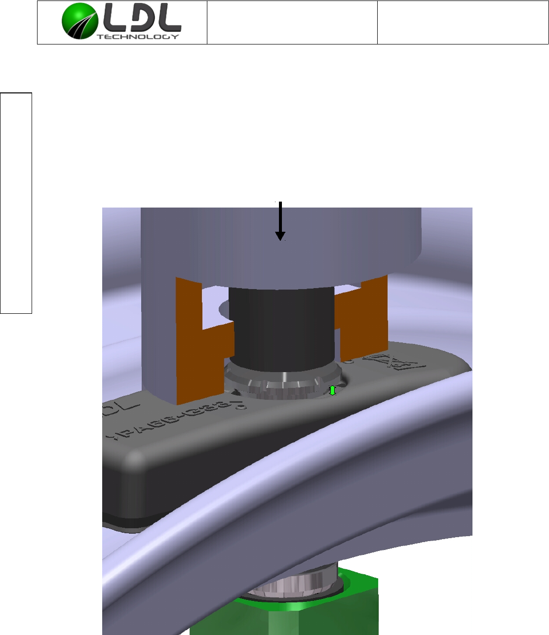
Details on WUS case displacement:
For a better understanding WUS holder is represented with a partial cut (orange area)
Now the screwdriver clutch is on the nut and the WUS holder has pushed down the WUS case.
There is a gap between the nut head and the WUS case (green arrow on scheme) so we can
start screwing without the nut touching the WUS case and damaging the WUS anti rotation
embossed shapes.
During screwing the nut must be pressed onto the rim, so it is the nut which achieves the
coaxiality of the assembly in the valve hole and not the valve seal.
10.3. STEP 3
In case of L-Valve rotation under screwing action, hold the valve during the screwing process
with a PTFE spanner to avoid marking and scratch onto the valve anodization.
LDL recommend to screw according the profile explained below :
Screw the valve by hand till get contact between valve seal and external rim side (around
5 complete turns). Screwing by hand on at least 1 turn is also accepted for industrial
production.
Screw the nut with a torque gun at constant speed :
No minimum, 50 rpm recommended , 100 rpm maximum , do not exceed 120rpm MAX
FINAL TORQUE: 5 Nm ± 0.5 Nm
C3070200010-E2-WUS Mounting process mode.odt LDL Technology SAS
24/ 24 Toulouse – France
Copyrights 2016
Torque gun speed , in RPM
110 120
050 100
Screwing tool
Atlas Copco reference
LUM12 HRX8-50 LUM12 HRX8-110